WO2020217843A1 - Dispositif cpap - Google Patents
Dispositif cpap Download PDFInfo
- Publication number
- WO2020217843A1 WO2020217843A1 PCT/JP2020/013725 JP2020013725W WO2020217843A1 WO 2020217843 A1 WO2020217843 A1 WO 2020217843A1 JP 2020013725 W JP2020013725 W JP 2020013725W WO 2020217843 A1 WO2020217843 A1 WO 2020217843A1
- Authority
- WO
- WIPO (PCT)
- Prior art keywords
- unit
- connection surface
- housing
- connection
- electrical connection
- Prior art date
Links
Images


Classifications
-
- A—HUMAN NECESSITIES
- A61—MEDICAL OR VETERINARY SCIENCE; HYGIENE
- A61M—DEVICES FOR INTRODUCING MEDIA INTO, OR ONTO, THE BODY; DEVICES FOR TRANSDUCING BODY MEDIA OR FOR TAKING MEDIA FROM THE BODY; DEVICES FOR PRODUCING OR ENDING SLEEP OR STUPOR
- A61M16/00—Devices for influencing the respiratory system of patients by gas treatment, e.g. mouth-to-mouth respiration; Tracheal tubes
- A61M16/10—Preparation of respiratory gases or vapours
- A61M16/14—Preparation of respiratory gases or vapours by mixing different fluids, one of them being in a liquid phase
- A61M16/16—Devices to humidify the respiration air
-
- A—HUMAN NECESSITIES
- A61—MEDICAL OR VETERINARY SCIENCE; HYGIENE
- A61M—DEVICES FOR INTRODUCING MEDIA INTO, OR ONTO, THE BODY; DEVICES FOR TRANSDUCING BODY MEDIA OR FOR TAKING MEDIA FROM THE BODY; DEVICES FOR PRODUCING OR ENDING SLEEP OR STUPOR
- A61M16/00—Devices for influencing the respiratory system of patients by gas treatment, e.g. mouth-to-mouth respiration; Tracheal tubes
- A61M16/0057—Pumps therefor
- A61M16/0066—Blowers or centrifugal pumps
- A61M16/0069—Blowers or centrifugal pumps the speed thereof being controlled by respiratory parameters, e.g. by inhalation
-
- A—HUMAN NECESSITIES
- A61—MEDICAL OR VETERINARY SCIENCE; HYGIENE
- A61M—DEVICES FOR INTRODUCING MEDIA INTO, OR ONTO, THE BODY; DEVICES FOR TRANSDUCING BODY MEDIA OR FOR TAKING MEDIA FROM THE BODY; DEVICES FOR PRODUCING OR ENDING SLEEP OR STUPOR
- A61M16/00—Devices for influencing the respiratory system of patients by gas treatment, e.g. mouth-to-mouth respiration; Tracheal tubes
- A61M16/021—Devices for influencing the respiratory system of patients by gas treatment, e.g. mouth-to-mouth respiration; Tracheal tubes operated by electrical means
- A61M16/022—Control means therefor
- A61M16/024—Control means therefor including calculation means, e.g. using a processor
-
- A—HUMAN NECESSITIES
- A61—MEDICAL OR VETERINARY SCIENCE; HYGIENE
- A61M—DEVICES FOR INTRODUCING MEDIA INTO, OR ONTO, THE BODY; DEVICES FOR TRANSDUCING BODY MEDIA OR FOR TAKING MEDIA FROM THE BODY; DEVICES FOR PRODUCING OR ENDING SLEEP OR STUPOR
- A61M16/00—Devices for influencing the respiratory system of patients by gas treatment, e.g. mouth-to-mouth respiration; Tracheal tubes
- A61M16/10—Preparation of respiratory gases or vapours
- A61M16/1075—Preparation of respiratory gases or vapours by influencing the temperature
- A61M16/109—Preparation of respiratory gases or vapours by influencing the temperature the humidifying liquid or the beneficial agent
-
- A—HUMAN NECESSITIES
- A61—MEDICAL OR VETERINARY SCIENCE; HYGIENE
- A61M—DEVICES FOR INTRODUCING MEDIA INTO, OR ONTO, THE BODY; DEVICES FOR TRANSDUCING BODY MEDIA OR FOR TAKING MEDIA FROM THE BODY; DEVICES FOR PRODUCING OR ENDING SLEEP OR STUPOR
- A61M16/00—Devices for influencing the respiratory system of patients by gas treatment, e.g. mouth-to-mouth respiration; Tracheal tubes
- A61M16/0057—Pumps therefor
- A61M16/0066—Blowers or centrifugal pumps
-
- A—HUMAN NECESSITIES
- A61—MEDICAL OR VETERINARY SCIENCE; HYGIENE
- A61M—DEVICES FOR INTRODUCING MEDIA INTO, OR ONTO, THE BODY; DEVICES FOR TRANSDUCING BODY MEDIA OR FOR TAKING MEDIA FROM THE BODY; DEVICES FOR PRODUCING OR ENDING SLEEP OR STUPOR
- A61M16/00—Devices for influencing the respiratory system of patients by gas treatment, e.g. mouth-to-mouth respiration; Tracheal tubes
- A61M16/06—Respiratory or anaesthetic masks
-
- A—HUMAN NECESSITIES
- A61—MEDICAL OR VETERINARY SCIENCE; HYGIENE
- A61M—DEVICES FOR INTRODUCING MEDIA INTO, OR ONTO, THE BODY; DEVICES FOR TRANSDUCING BODY MEDIA OR FOR TAKING MEDIA FROM THE BODY; DEVICES FOR PRODUCING OR ENDING SLEEP OR STUPOR
- A61M16/00—Devices for influencing the respiratory system of patients by gas treatment, e.g. mouth-to-mouth respiration; Tracheal tubes
- A61M16/08—Bellows; Connecting tubes ; Water traps; Patient circuits
- A61M16/0816—Joints or connectors
-
- A—HUMAN NECESSITIES
- A61—MEDICAL OR VETERINARY SCIENCE; HYGIENE
- A61M—DEVICES FOR INTRODUCING MEDIA INTO, OR ONTO, THE BODY; DEVICES FOR TRANSDUCING BODY MEDIA OR FOR TAKING MEDIA FROM THE BODY; DEVICES FOR PRODUCING OR ENDING SLEEP OR STUPOR
- A61M16/00—Devices for influencing the respiratory system of patients by gas treatment, e.g. mouth-to-mouth respiration; Tracheal tubes
- A61M16/0003—Accessories therefor, e.g. sensors, vibrators, negative pressure
- A61M2016/0027—Accessories therefor, e.g. sensors, vibrators, negative pressure pressure meter
-
- A—HUMAN NECESSITIES
- A61—MEDICAL OR VETERINARY SCIENCE; HYGIENE
- A61M—DEVICES FOR INTRODUCING MEDIA INTO, OR ONTO, THE BODY; DEVICES FOR TRANSDUCING BODY MEDIA OR FOR TAKING MEDIA FROM THE BODY; DEVICES FOR PRODUCING OR ENDING SLEEP OR STUPOR
- A61M16/00—Devices for influencing the respiratory system of patients by gas treatment, e.g. mouth-to-mouth respiration; Tracheal tubes
- A61M16/0003—Accessories therefor, e.g. sensors, vibrators, negative pressure
- A61M2016/003—Accessories therefor, e.g. sensors, vibrators, negative pressure with a flowmeter
- A61M2016/0033—Accessories therefor, e.g. sensors, vibrators, negative pressure with a flowmeter electrical
- A61M2016/0039—Accessories therefor, e.g. sensors, vibrators, negative pressure with a flowmeter electrical in the inspiratory circuit
-
- A—HUMAN NECESSITIES
- A61—MEDICAL OR VETERINARY SCIENCE; HYGIENE
- A61M—DEVICES FOR INTRODUCING MEDIA INTO, OR ONTO, THE BODY; DEVICES FOR TRANSDUCING BODY MEDIA OR FOR TAKING MEDIA FROM THE BODY; DEVICES FOR PRODUCING OR ENDING SLEEP OR STUPOR
- A61M39/00—Tubes, tube connectors, tube couplings, valves, access sites or the like, specially adapted for medical use
- A61M39/10—Tube connectors; Tube couplings
- A61M2039/1022—Tube connectors; Tube couplings additionally providing electrical connection
-
- A—HUMAN NECESSITIES
- A61—MEDICAL OR VETERINARY SCIENCE; HYGIENE
- A61M—DEVICES FOR INTRODUCING MEDIA INTO, OR ONTO, THE BODY; DEVICES FOR TRANSDUCING BODY MEDIA OR FOR TAKING MEDIA FROM THE BODY; DEVICES FOR PRODUCING OR ENDING SLEEP OR STUPOR
- A61M2205/00—General characteristics of the apparatus
- A61M2205/12—General characteristics of the apparatus with interchangeable cassettes forming partially or totally the fluid circuit
- A61M2205/121—General characteristics of the apparatus with interchangeable cassettes forming partially or totally the fluid circuit interface between cassette and base
- A61M2205/122—General characteristics of the apparatus with interchangeable cassettes forming partially or totally the fluid circuit interface between cassette and base using evacuated interfaces to enhance contact
-
- A—HUMAN NECESSITIES
- A61—MEDICAL OR VETERINARY SCIENCE; HYGIENE
- A61M—DEVICES FOR INTRODUCING MEDIA INTO, OR ONTO, THE BODY; DEVICES FOR TRANSDUCING BODY MEDIA OR FOR TAKING MEDIA FROM THE BODY; DEVICES FOR PRODUCING OR ENDING SLEEP OR STUPOR
- A61M2205/00—General characteristics of the apparatus
- A61M2205/33—Controlling, regulating or measuring
- A61M2205/3368—Temperature
-
- A—HUMAN NECESSITIES
- A61—MEDICAL OR VETERINARY SCIENCE; HYGIENE
- A61M—DEVICES FOR INTRODUCING MEDIA INTO, OR ONTO, THE BODY; DEVICES FOR TRANSDUCING BODY MEDIA OR FOR TAKING MEDIA FROM THE BODY; DEVICES FOR PRODUCING OR ENDING SLEEP OR STUPOR
- A61M2205/00—General characteristics of the apparatus
- A61M2205/42—Reducing noise
-
- A—HUMAN NECESSITIES
- A61—MEDICAL OR VETERINARY SCIENCE; HYGIENE
- A61M—DEVICES FOR INTRODUCING MEDIA INTO, OR ONTO, THE BODY; DEVICES FOR TRANSDUCING BODY MEDIA OR FOR TAKING MEDIA FROM THE BODY; DEVICES FOR PRODUCING OR ENDING SLEEP OR STUPOR
- A61M2205/00—General characteristics of the apparatus
- A61M2205/82—Internal energy supply devices
- A61M2205/8237—Charging means
- A61M2205/8243—Charging means by induction
Definitions
- the present disclosure relates to a CPAP (Continuous Positive Airway Pressure) device that sends air taken into the device into the respiratory tract of the user.
- CPAP Continuous Positive Airway Pressure
- CPAP device continuous positive airway pressure (CPAP device) that supplies fluid to a user for the treatment of sleep-related disorders such as obstructive sleep apnea syndrome (OSA).
- a CPAP device has a blower with a built-in fan, and supplies fluid (for example, air) from the blower to a mask worn on the user's mouth or nose at a pressure higher than atmospheric pressure to open the airway.
- fluid for example, air
- the CPAP device is a device that is required to be used continuously every day, for example, when the user stays out, it is necessary to carry the CPAP device. Therefore, the CPAP device is required to be smaller and lighter. However, providing a humidifier may reduce the portability of the device.
- the purpose of the present disclosure is to provide a CPAP device having a humidifying function and high portability.
- the CPAP device is a CPAP device that sends air introduced into the device into the airway of a user, and includes a first unit and a second unit attached to and detached from the first unit.
- the first unit includes a first housing having a first introduction section and a first lead-out section, a blower for leading out air introduced from the first introduction section from the first lead-out section, and the first housing.
- the second unit includes a first electrical connection portion and a first guide portion provided on the body, and the second unit is derived from a second housing having a second introduction portion and a second lead-out portion, and the second introduction portion.
- a humidifier for humidifying the introduced air, a second electrical connection portion electrically connected to the first electrical connection portion, and a second guide portion are included, and the first guide portion and the second guide portion are included. Is configured to guide the first electrical connection portion and the second electrical connection portion to a position where they can be electrically connected to each other by connecting the first lead-out unit and the second introduction unit.
- a CPAP device having a humidifying function and high portability.
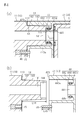
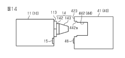
- (A) and (b) are partial cross-sectional views showing a connection portion between the main body unit and the base unit in the first embodiment.
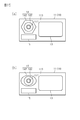
- (A) is a schematic diagram showing a first usage state of the CPAP device in each embodiment
- (b) is a schematic diagram showing a second usage state of the CPAP device.
- the explanatory view which shows the structure of the functional block of the CPAP apparatus in the 2nd use state in each embodiment.
- Explanatory drawing which shows the functional block of the CPAP apparatus in each embodiment.
- the explanatory view which shows the outline of the CPAP apparatus of the modification example in 1st Embodiment.
- the explanatory view which shows the outline of the CPAP apparatus of the modification example in 1st Embodiment.
- (A) and (b) are explanatory views showing an example of modification of the base in the first embodiment.
- a perspective view of the CPAP device according to the second embodiment as viewed from another angle. The figure explaining the movable 2nd electrical connection part in 2nd Embodiment.
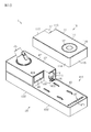
- the CPAP device 1 includes a main body unit 10 as a first unit and a base unit 40 as a second unit.
- the main body unit 10 includes a blower 22 as a main component.
- the base unit 40 includes a humidifier 51 as a main component.
- the base unit 40 is removable from the main body unit 10.
- the CPAP device 1 is configured so that it can be used in the first use state and the second use state.
- the first used state is a state in which the base unit 40 is attached to the main body unit 10
- the second used state is a state in which the base unit 40 is not attached to the main body unit 10.
- the main body unit 10 and the base unit 40 are used.
- the second used state only the main body unit 10 is used, and the base unit 40 is not used.
- the CPAP device 1 of the present embodiment is highly convenient not only at home but also at night by configuring the CPAP device 1 with a plurality of units and the plurality of units being detachably attached to each other. It is intended to demonstrate sexuality.
- the CPAP device 1 can be used in the above-mentioned first usage state by attaching the base unit 40 to the main body unit 10.
- the CPAP device 1 provided with the humidifier 51 can supply humidified air to the user.
- the CPAP device 1 can be used in the second used state in which the base unit 40 is not attached to the main body unit 10. In this second use state, since the CPAP device 1 has only the main body unit 10, it is sufficient to carry only the main body unit 10, and high portability can be obtained.
- the CPAP device 1 can also be used in the second used state when at home.
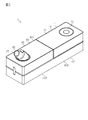
- the main body unit 10 has a flat substantially rectangular parallelepiped outer shape, and the outer shell thereof is composed of the first housing 11.
- the first housing 11 has an upper surface 111 and a lower surface 112 facing opposite sides in the thickness direction, and four side surfaces 113, 114, 115, 116 connecting the upper surface 111 and the lower surface 112.
- the upper surface 111 is an operation surface provided with the operation unit 12.
- the operation unit 12 includes an annular member and a plurality of switches that are turned on and off by the member. It is formed by turning the switch on and off, and the set value can be changed by the annular operation unit 12.
- the lower surface 112 is a mounting surface that is mounted on the base unit 40 in the first used state and mounted on a floor surface, a table, or the like in the second used state.
- the side surface 113 is a connection surface connected to the base unit 40 in the first use state, and is hereinafter referred to as the first connection surface 113.
- the side surface 113 is orthogonal to the upper surface 111 and the lower surface 112.
- the first introduction unit 13 for introducing the air outside the first housing 11 into the first housing 11 and the inside to the outside of the first housing 11 And a first lead-out unit 14 for leading out air are provided.
- the first out-licensing unit 14 is an example of a first guide unit and a convex portion.
- the first introduction unit 13 has a plurality of through holes. Due to these plurality of through holes, the first housing 11 has a first introduction port 131.
- the first connection surface 113 of the first housing 11 is provided with a first electrical connection portion 15 for electrically connecting the main body unit 10 and the base unit 40.
- the first electrical connection portion 15 electrically connects the main body unit 10 and the base unit 40.
- the first electrical connection portion 15 is a connector having terminals that are connected to and separated from the second electrical connection portion 46 of the base unit 40.
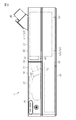
- the base unit 40 includes a second housing 41.
- the second housing 41 has a humidifying portion 42 on which the humidifier 51 shown in FIGS. 6 and 8 is provided, and a mounting portion 43 on which the main body unit 10 is mounted.
- the humidifying portion 42 is formed thicker than the mounting portion 43.
- the lower surface 422 of the humidifying portion 42 and the lower surface 432 of the mounting portion 43 are flush with each other. Therefore, the upper surface 421 of the humidifying portion 42 is located higher than the upper surface 421 of the mounting portion 43.
- the second housing 41 has an elongated substantially rectangular parallelepiped outer shape in which a notch portion 411 is provided in a part in the longitudinal direction by the humidifying portion 42 and the mounting portion 43.
- These lower surfaces 422 and 432 are mounting surfaces that are mounted on a floor surface, a table, or the like in the first use state.
- a second lead-out portion 45 is provided on the upper surface 421 of the humidifying portion 42.
- the second housing 41 has a second outlet 451 that draws air from the inside of the second housing 41 by the second leading unit 45.
- the air tube 2 (see FIGS. 5A and 5B) is connected to the second outlet 45 (second outlet 451) in the first use state.
- the upper surface 431 of the mounting portion 43 is a surface on which the main body unit 10 is mounted. The difference in height between the upper surface 421 of the humidifying portion 42 and the upper surface 431 of the mounting portion 43 corresponds to the thickness of the first housing 11 of the main body unit 10.
- the side surface facing the cutout portion 411 is the second connecting surface 423 to which the main body unit 10 is connected.
- the second connection surface 423 is provided with a second introduction portion 44 for introducing air from the outside of the second housing 41.
- the second introduction portion 44 has a through hole
- the second housing 41 has a second introduction port 441 due to the through hole.
- a second electrical connection portion 46 is provided on the second connection surface 423.
- the second electrical connection portion 46 is electrically connected to the first electrical connection portion 15 of the main body unit 10 by attaching the base unit 40 to the main body unit 10.
- the second electrical connection portion 46 is a connector having a terminal that is connected to and separated from the first electrical connection portion 15.
- the first electrical connection unit 15 and the second electrical connection unit 46 perform electrical connection and disconnection between the main body unit 10 and the base unit 40.
- the first electrical connection unit 15 and the second electrical connection unit 46 are used for supplying power to the base unit 40 and transmitting / receiving data by a digital signal.
- power supply and data transmission / reception can be performed by separate connection units. For example, non-contact power supply, short-range wireless communication, and the like can be used together.
- the upper surface 431 of the mounting portion 43 of the second housing 41 described above is provided with a third introduction portion 47 that introduces air from the outside of the second housing 41.
- the third introduction portion 47 has a plurality of through holes penetrating the second housing 41, and the second housing 41 has a third introduction port 471 due to the plurality of through holes.
- the second connection surface 423 is provided with a third lead-out unit 48 for leading out air from the second housing 41.
- the third outlet 48 has a through hole that penetrates the second housing 41, and the second housing 41 has a third outlet 481 due to this through hole.
- the main body unit 10 By arranging the main body unit 10 in the cutout portion 411 of the base unit 40, the lower surface 112 of the first housing 11 and the upper surface 431 of the mounting portion 43 of the second housing 41 face each other, and the first housing The first connection surface 113 of the body 11 and the second connection surface 423 of the second housing 41 face each other. Then, the first lead-out unit 14 provided on the first connection surface 113 of the first housing 11 and the second introduction unit 44 provided on the second connection surface 423 of the second housing 41 are connected to each other. .. Further, the first introduction unit 13 provided on the first connection surface 113 of the first housing 11 and the third lead-out unit 48 provided on the second connection surface 423 of the second housing 41 are connected to each other. ..
- the CPAP device 1 has a substantially rectangular parallelepiped shape as a whole. Then, the air introduced into the second housing 41 by the third introduction unit 47 of the second housing 41 is the third leading unit 48 of the second housing 41 and the first introduction unit 13 of the first housing 11. It is introduced into the first housing 11 via and. Then, the air in the first housing 11 is introduced into the second housing 41 via the first lead-out unit 14 of the first housing 11 and the second introduction unit 44 of the second housing 41. Then, it is led out from the second out-licensing unit 45 of the second housing 41 to the outside.
- the main body unit 10 when the base unit 40 is not attached to the main body unit 10, the first connection surface 113 of the first housing 11 is exposed to the outside. Therefore, the first introduction section 13 and the first lead-out section 14 provided on the first connection surface 113 of the first housing 11 are in a state of being open to the outside. As a result, the main body unit 10 introduces air from the outside of the first housing 11 into the first housing 11 by the first introduction unit 13, and the air in the first housing 11 is external from the first lead-out unit 14. Derived to. That is, the main body unit 10 functions independently as a CPAP device.
- the first out-licensing unit 14 projects from the first connecting surface 113.
- the first out-licensing unit 14 includes a base portion 142 and a connecting cylinder portion 143.
- the base 142 is connected to the first connection surface 113.
- the connecting cylinder portion 143 extends from the base portion 142 in the direction opposite to the first connecting surface.
- the base 142 is formed in a cylindrical shape.
- the outer peripheral surface of the base portion 142 is a cylindrical surface, and the external dimensions of the base portion 142 are the same in the direction of projecting from the side of the first connecting surface 113.
- the connecting cylinder portion 143 is formed in a tapered shape in which the outer diameter dimension becomes smaller toward the tip end.
- the first lead-out portion 14 has a base portion 142 having a cylindrical peripheral surface and a connecting cylinder portion 143 having a tapered peripheral surface.
- connection cylinder portion 143 is formed with a connection recess 144 from the tip thereof toward the base portion 142. Through holes penetrating the base portion 142, the connecting cylinder portion 143, and the connecting recess 144 communicate the outside and the inside of the first housing 11.
- the first housing 11 has a first outlet 141 that guides air to the outside of the first housing 11 by the first lead-out unit 14.
- the second introduction portion 44 has a housing portion 442 and a connecting convex portion 444.
- the accommodating portion 442 is an example of a second guide portion and a recess.
- the accommodating portion 442 is recessed from the second connection surface 423 of the second housing 41 toward the inside of the second housing 41. As shown in FIG. 4A, the accommodating portion 442 accommodates the first lead-out portion 14 of the first housing 11.
- the accommodating portion 442 has an inner wall 443a and a wall portion 443b.
- the inner wall 443a has a cylindrical shape, and the inner diameter dimension thereof is set to be slightly larger than the outer diameter dimension of the base portion 142 of the first lead-out portion 14. That is, the CPAP device 1 has a gap (clearance) GA between the inner wall 443a (inner surface) of the accommodating portion 442 and the peripheral surface of the base portion 142 of the first lead-out portion 14.
- the size of the gap GA is the distance between the base 142 of the first lead-out unit 14 and the inner wall 443a of the accommodating unit 442, and the distance depends on the first electrical connection portion 15 and the second electrical connection portion 46. It is set.
- a connecting convex portion 444 is provided on the wall portion 443b of the accommodating portion 442.
- the connecting convex portion 444 projects toward the open end of the accommodating portion 442.
- the connecting convex portion 444 is formed in a cylindrical shape.
- the second housing 41 has a second introduction port 441 that introduces air into the inside of the second housing 41 by the connecting convex portion 444.
- a sealing member 445 is provided on the outer peripheral surface of the connecting convex portion 444.
- the sealing member 445 is housed in a groove provided along the outer peripheral surface of the connecting convex portion 444.
- the sealing member 445 is in close contact with the inner peripheral surface of the connection recess 144 of the first lead-out portion 14 of the first housing 11.
- the sealing member 445 is, for example, an annular sealing member.
- the sealing member 445 seals between the connecting convex portion 444 and the connecting concave portion 144. That is, the sealing member 445 prevents air from leaking between the first lead-out unit 14 and the second introduction unit 44.
- the first housing 11 is provided with a first electrical connection portion 15.
- the first electrical connection portion 15 is a female connector and is internally provided in the first housing 11 so as not to protrude from the first connection surface 113.
- the second housing 41 is provided with a second electrical connection portion 46.
- a part of the second electrical connection portion 46 projects from the second connection surface 423 of the second housing 41.
- the second electrical connection portion 46 is a male connector.
- the second electrical connection portion 46 is inserted into the first electrical connection portion 15.
- the main body unit 10 and the base unit 40 are electrically connected by the first electrical connection portion 15 and the second electrical connection portion 46.
- the length L14 of the first lead-out unit 14 is the length from the first connection surface 113 of the first housing 11 to the tip of the first lead-out unit 14.
- the length L46 of the second electrical connection portion 46 is the length from the second connection surface 423 of the second housing 41 to the tip of the second electrical connection portion 46.
- the length L14 of the first lead-out unit 14 is longer than the length L46 of the second electrical connection unit 46. Therefore, when the base unit 40 is attached to the main body unit 10, the tip of the first lead-out unit 14 is first inserted into the second introduction unit 44, and then the second electrical connection unit 46 is inserted into the first electrical connection unit 15. To.
- the first lead-out portion 14 has a base portion 142 having a cylindrical peripheral surface and a connecting cylinder portion 143 having a tapered peripheral surface.
- the first lead-out unit 14 moves toward the center of the second introduction unit 44 by the connecting cylinder portion 143 having a tapered peripheral surface.
- the first lead-out unit 14 can be inserted into the connection concave portion 144 of the first lead-out unit 14 so that the connection convex portion 444 of the second introduction unit 44 can be inserted. Will be guided.
- the first electrical connection unit 15 of the first housing 11 and the second electrical connection unit 46 of the second housing 41 are electrically connected to each other.
- the first out-licensing unit 14 is guided to a position where it is possible.
- the outer diameter dimension of the connecting cylinder portion 143 on the side of the base portion 142 is equal to the outer diameter dimension of the base portion 142.
- the outer dimension of the base 142 is smaller than the inner diameter of the accommodating portion 442 of the second housing 41. Therefore, as shown in FIG. 4A, the base 142 is inserted into the accommodating portion 442. Then, a gap (clearance) GA is generated between the outer peripheral surface of the base portion 142 and the inner peripheral surface of the accommodating portion 442.
- the first housing 11 and the second housing 41 can be relatively moved along the first connection surface 113 and the second connection surface 423. This movement enables further alignment of the first electrical connection portion 15 and the second electrical connection portion 46.
- FIG. 5 (a) and 5 (b) schematically show the usage state of the CPAP device 1 of the present embodiment.
- FIG. 5A shows a first usage state
- FIG. 5B shows a second usage state.
- the CPAP device 1 in the first use state, is used in a state where the base unit 40 is attached to the main body unit 10.
- the first end portion of the air tube 2 is connected to the second lead-out portion 45 provided in the base unit 40, and the second end portion of the air tube 2 is connected to the mask 3.
- the mask 3 is worn, for example, so as to cover the nose or mouth of the user 4.
- the CPAP device 1 is used only for the main body unit 10 to which the base unit 40 is not attached.
- the first end portion of the air tube 2 is connected to the first lead-out portion 14 provided in the main body unit 10, and the second end portion of the air tube 2 is connected to the mask 3.
- the mask 3 is worn, for example, so as to cover the nose or mouth of the user 4.
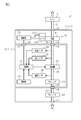
- FIG. 6 shows the configuration of the functional block in the first used state of the CPAP device 1 of the present embodiment
- FIG. 7 shows the configuration of the functional block in the second used state of the CPAP device 1.
- the main body unit 10 of the CPAP device 1 includes a first control unit 21, an operation unit 12, a blower 22, a silencer 23, a flow rate sensor 24, a pressure sensor 25, and a temperature sensor 26. ..
- the base unit 40 includes a humidifier 51, a silencer 52, and a second control unit 53.
- the main body unit 10 includes a first flow path 16 between the first introduction unit 13 and the first lead-out unit 14.
- a blower 22 is provided in the first flow path 16.
- the blower 22 is composed of, for example, a centrifugal fan.
- the blower 22 is installed in the blower room provided in the first housing 11.
- the blower room is a part of the first flow path 16, and the blower room 22 is arranged on the first flow path 16.
- a silencer 23 is provided between the first introduction unit 13 and the blower 22 in the first flow path 16.
- the silencer 23 suppresses leakage of noise generated by the blower 22 (operating noise of the drive motor, wind noise, etc.) to the outside of the first housing 11.
- the pressure sensor 25, the flow rate sensor 24, and the temperature sensor 26 are provided in the first flow path 16.
- the pressure sensor 25 is a sensor for detecting the pressure of the air sent out by the blower 22.
- the flow rate sensor 24 is a sensor for detecting the flow rate of air between the main body unit 10 and the air tube 2.
- the temperature sensor 26 is a sensor for detecting the temperature of the air introduced from the outside of the main body unit 10.
- the first control unit 21 operates an arithmetic processing unit (CPU: Central Processing Unit) for executing a program, a storage unit (ROM: Read Only Memory / RAM: Random Access Memory), a communication unit, and a blower 22 as main components. Includes a drive unit, etc.
- the storage unit includes a ROM that stores data non-volatilely and a RAM that stores data volatilely.
- the data stored in the storage unit is data generated by executing a program by the arithmetic processing unit, data input via the operation unit 12, data measured by the various sensors described above, and external communication by the communication unit. Includes data sent and received between.
- the processing in the arithmetic processing unit is realized by each hardware and the software executed by the arithmetic processing unit.
- Such software is stored in advance in the storage unit.
- Accepting the operation of the operation unit 12, controlling the drive motor that drives the blower 22, communication with the outside, and the like are also realized by software.
- the first control unit 21 increases or decreases the rotation speed of the blower 22 by control such as feedback control and feedforward control based on the flow rate value and the pressure value detected by the flow rate sensor 24 and the pressure sensor 25. , Control the amount of air sent out, etc.
- the first control unit 21 determines the exhalation state of the user based on the values measured by the flow rate sensor 24 and the pressure sensor 25, and the pressure value of the air supplied to the user so as to synchronize with the exhalation state. To control. Further, the first control unit 21 transmits the temperature value detected by the temperature sensor 26 to the outside.
- the second housing 41 of the base unit 40 has a second flow path 49 between the second introduction section 44 and the second lead-out section 45, and a third section between the third introduction section 47 and the third lead-out section 48. It is provided with a flow path 50.
- a humidifier 51 is provided in the second flow path 49. The humidifier 51 adds humidity to the air flowing through the second flow path 49 in the first use state. As a result, the CPAP device 1 imparts appropriate moisture to the air sent out toward the user's respiratory tract.
- the humidifier 51 is a heating type humidifier.
- the humidifier 51 includes a container 511, a heater 512, and a temperature sensor 513.
- the container 511 is configured to be removable from the second housing 41.
- Container 511 stores water.
- the container 511 has an introduction pipe communicating with the second introduction portion 44, and air is supplied into the container 511 through the introduction pipe.
- the container 511 has a heater pad corresponding to the heater 512.
- the heater 512 heats the water in the container 511.
- the temperature sensor 513 detects the temperature of the heater 512.
- the second control unit 53 operates an arithmetic processing unit (CPU), a storage unit (ROM / RAM), a communication unit, and a humidifier 51 for executing a program as main components. Includes a drive unit, etc.
- the storage unit includes a ROM that stores data non-volatilely and a RAM that stores data volatilely.
- the data stored in the storage unit is the data generated by the execution of the program by the arithmetic processing unit, the heater temperature measured by the temperature sensor 513, and the transmission / reception between the communication unit and the first control unit 21 in the first usage state. Includes data, etc.
- the data received from the first control unit 21 includes the temperature value of air measured by the temperature sensor 26 of the main unit 10.
- the data received from the first control unit 21 may include data input via the operation unit 12.
- the processing in the arithmetic processing unit is realized by each hardware and the software executed by the arithmetic processing unit. Such software is stored in advance in the storage unit. Control of the heater 512 of the humidifier 51, communication with the first control unit 21, and the like are also realized by software.
- the second control unit 53 sets a target temperature for heating the water in the container 511 based on the temperature of the air received from the first control unit 21.
- the second control unit 53 sets the target temperature by, for example, a table or a calculation formula stored in the storage unit.
- the second control unit 53 drives the heater 512 so that the heater temperature becomes the target temperature by control such as feedback control and feedforward control based on the heater temperature detected by the temperature sensor 513.
- the water temperature in the container 511 is adjusted by the heater 512. This gives the air passing through the container 511 the desired humidity.
- the second control unit 53 may stop the humidifier 51, that is, stop the control of the heater 512, based on the temperature of the air received from the first control unit 21.
- a silencer 52 is provided in the third flow path 50. As shown in FIG. 8, the silencer 52 is provided in the mounting portion 43 on which the main body unit 10 is mounted in the base unit 40.
- the silencer 52 has a size slightly smaller than the size (outer shape) of the main body unit 10. As the volume of the silencer 52 increases, the quietness of the CPAP device 1 is enhanced.
- the silencer 52 is composed of, for example, a resonance tube branched from the third flow path 50.
- the resonance tube is composed of a meandering flow path.
- the resonance tube is also called a Helmholtz resonator or a resonator, and has a function of attenuating noise in a predetermined frequency band.
- the resonant tube attenuates sound in a frequency band determined by its natural frequency.
- the main body unit 10 includes a power supply unit 55.
- An AC adapter (not shown) is connected to the power supply unit 55.
- the power supply unit 55 generates the operating power required for the main unit 10 and the base unit 40.
- the operating power is supplied to the second control unit 53 of the base unit 40 and the like via the first electrical connection unit 15 of the main unit 10 and the second electrical connection unit 46 of the base unit 40.
- the CPAP device 1 includes a main body unit 10 and a base unit 40 attached to the main body unit 10.
- the CPAP device 1 When the CPAP device 1 is at home, the CPAP device 1 can be used in the above-mentioned first usage state by attaching the base unit 40 to the main body unit 10. In this first use state, by attaching the base unit 40 to the main body unit 10, the CPAP device 1 provided with the humidifier 51 can supply humidified air to the user. When staying out, the CPAP device 1 can be used in a second use state in which the base unit 40 is not attached to the main body unit 10. In this second use state, since the CPAP device 1 has only the main body unit 10, it is sufficient to carry only the main body unit 10, and high portability can be obtained.
- the first housing 11 of the main body unit 10 has a first introduction unit 13, a first lead-out unit 14, and a first electrical connection unit 15.
- the first lead-out unit 14 and the first electrical connection unit 15 are provided on the first connection surface 113 of the first housing 11.
- the second housing 41 of the base unit 40 has a second introduction section 44, a second lead-out section 45, and a second electrical connection section 46.
- the second introduction unit 44 and the second electrical connection unit 46 are provided on the second connection surface 423 facing the first connection surface 113 of the first housing 11 in the first use state.
- the first out-licensing unit 14 has an annular base portion 142 and a connecting cylinder portion 143 extending from the base portion 142.
- the connecting cylinder portion 143 is formed in a tapered shape in which the outer diameter dimension becomes smaller toward the tip end.
- the first lead-out portion 14 has a base portion 142 having a cylindrical peripheral surface and a connecting cylinder portion 143 having a tapered peripheral surface.
- the first out-licensing unit 14 includes a base portion 142 and a connecting cylinder portion 143.
- the base 142 is connected to the first connection surface 113.
- the connecting cylinder portion 143 extends from the base portion 142 in the direction opposite to the first connecting surface.
- the base 142 is formed in a cylindrical shape.
- the outer peripheral surface of the base portion 142 is a cylindrical surface, and the external dimensions of the base portion 142 are the same in the direction of projecting from the side of the first connecting surface 113.
- the connecting cylinder portion 143 is formed in a tapered shape in which the outer diameter dimension becomes smaller toward the tip end.
- the second introduction portion 44 has a housing portion 442 and a connecting convex portion 444.
- the accommodating portion 442 is recessed from the second connection surface 423 of the second housing 41 toward the inside of the second housing 41. As shown in FIG. 4A, the accommodating portion 442 accommodates the first lead-out portion 14 of the first housing 11.
- the first lead-out unit 14 When the first lead-out unit 14 is inserted into the second introduction unit 44, the first lead-out unit 14 moves toward the center of the second introduction unit 44 by the connecting cylinder portion 143 having a tapered peripheral surface. By moving the first lead-out unit 14 with respect to the second introduction unit 44, the first lead-out unit 14 can be inserted into the connection concave portion 144 of the first lead-out unit 14 so that the connection convex portion 444 of the second introduction unit 44 can be inserted. Will be guided. Therefore, the first derivation unit 14 and the second introduction unit 44 can be easily connected.
- the first lead-out unit 14 with respect to the second introduction unit 44 by moving the first lead-out unit 14 with respect to the second introduction unit 44, the first electrical connection unit 15 of the first housing 11 and the second electrical connection unit 46 of the second housing 41 can be electrically connected to each other.
- the first housing 11 and the second housing 41 are relatively guided to such positions. That is, the first lead-out unit 14 and the second introduction unit 44 guide the first electrical connection unit 15 and the second electrical connection unit 46 to positions where they can be electrically connected to each other, the first guide unit and the second guide unit. Functions as. With such a configuration, the first electrical connection portion 15 and the second electrical connection portion 46 can be easily connected.
- the outer diameter dimension of the connecting cylinder portion 143 on the side of the base portion 142 is equal to the outer diameter dimension of the base portion 142.
- the outer dimension of the base 142 is smaller than the inner diameter of the accommodating portion 442 of the second housing 41. Therefore, as shown in FIG. 4A, the base 142 is inserted into the accommodating portion 442. Then, a gap (clearance) GA is generated between the outer peripheral surface of the base portion 142 and the inner peripheral surface of the accommodating portion 442.
- the first housing 11 and the second housing 41 can be relatively moved along the first connection surface 113 and the second connection surface 423. This movement enables further alignment of the first electrical connection portion 15 and the second electrical connection portion 46.
- connection recess 144 is formed in the connection cylinder portion 143 of the first lead-out portion 14 from the tip thereof toward the base portion 142. Through holes penetrating the base portion 142, the connecting cylinder portion 143, and the connecting recess 144 communicate the outside and the inside of the first housing 11.
- the first housing 11 has a first outlet 141 that guides air to the outside of the first housing 11 by the first lead-out unit 14.
- the connecting convex portion 444 of the second introduction portion 44 is provided on the wall portion 443b of the accommodating portion 442.
- the connecting convex portion 444 projects toward the open end of the accommodating portion 442.
- the connecting convex portion 444 is formed in a cylindrical shape.
- the second housing 41 has a second introduction port 441 that introduces air into the inside of the second housing 41 by the connecting convex portion 444.
- a sealing member 445 is provided on the outer peripheral surface of the connecting convex portion 444.
- the sealing member 445 is housed in a groove provided along the outer peripheral surface of the connecting convex portion 444.
- the sealing member 445 is in close contact with the inner peripheral surface of the connection recess 144 of the first lead-out portion 14 of the first housing 11.
- the sealing member 445 is, for example, an annular sealing member.
- the sealing member 445 seals between the connecting convex portion 444 and the connecting concave portion 144. That is, the sealing member 445 prevents air from leaking between the first lead-out unit 14 and the second introduction unit 44.
- the second control unit 53 of the base unit 40 controls the humidifier 51 provided in the base unit 40. Therefore, the first control unit 21 of the main body unit 10 may control the blower 22 provided in the main body unit 10 and accept the operation of the operation unit 12. Therefore, the calculation load of the first control unit 21 and the like can be suppressed lower than that of the first control unit 21 that controls the entire CPAP device 1, and heat generation can be suppressed.
- the main body unit 10 when the base unit 40 is attached to the main body unit 10, the main body unit 10 is at a predetermined distance (for example, about 1.5 mm) from the upper surface 431 of the mounting portion 43 of the base unit 40. They are placed apart from each other.
- the third introduction unit 47 (see FIGS. 1 and 2) provided in the base unit 40 communicates with the space outside the CPAP device 1 through the gap between the base unit 40 and the main body unit 10. .. Therefore, intake can be efficiently performed without limiting the direction, and the main body unit 10 is located facing the third introduction unit 47 to suppress the leakage of noise from the third introduction unit 47 to the outside. Will be done.
- the CPAP device 1 can be used in the above-mentioned first usage state by attaching the base unit 40 to the main body unit 10 when at home. In this first use state, by attaching the base unit 40 to the main body unit 10, the CPAP device 1 provided with the humidifier 51 can supply humidified air to the user. When staying out, the CPAP device 1 can be used in a second use state in which the base unit 40 is not attached to the main body unit 10. In this second use state, since the CPAP device 1 has only the main body unit 10, it is sufficient to carry only the main body unit 10, and high portability can be obtained.
- the first out-licensing unit 14 includes a base portion 142 and a connecting cylinder portion 143.
- the base 142 is connected to the first connection surface 113.
- the connecting cylinder portion 143 extends from the base portion 142 in the direction opposite to the first connecting surface.
- the base 142 is formed in a cylindrical shape.
- the outer peripheral surface of the base portion 142 is a cylindrical surface, and the external dimensions of the base portion 142 are the same in the direction of projecting from the side of the first connecting surface 113.
- the connecting cylinder portion 143 is formed in a tapered shape in which the outer diameter dimension becomes smaller toward the tip end.
- the second introduction portion 44 has a housing portion 442 and a connecting convex portion 444.
- the accommodating portion 442 is recessed from the second connection surface 423 of the second housing 41 toward the inside of the second housing 41.
- the first lead-out unit 14 of the first housing 11 is housed in the storage unit 442.
- the first lead-out unit 14 when the first lead-out unit 14 is inserted into the second introduction unit 44, the first lead-out unit 14 moves toward the center of the second introduction unit 44 by the connecting cylinder portion 143 having a tapered peripheral surface. To do.
- the first lead-out unit 14 By moving the first lead-out unit 14 with respect to the second introduction unit 44, the first lead-out unit 14 can be inserted into the connection concave portion 144 of the first lead-out unit 14 so that the connection convex portion 444 of the second introduction unit 44 can be inserted. Will be guided. Therefore, the first derivation unit 14 and the second introduction unit 44 can be easily connected.
- the first electrical connection unit 15 of the first housing 11 and the second electrical connection unit 46 of the second housing 41 are electrically connected to each other.
- the first housing 11 and the second housing 41 are relatively guided to the possible positions. That is, the first lead-out unit 14 and the second introduction unit 44 guide the first electrical connection unit 15 and the second electrical connection unit 46 to positions where they can be electrically connected to each other, the first guide unit and the second guide unit. Functions as. With such a configuration, the first electrical connection portion 15 and the second electrical connection portion 46 can be easily connected.
- the outer diameter dimension of the connecting cylinder portion 143 on the side of the base portion 142 is equal to the outer diameter dimension of the base portion 142.
- the outer dimension of the base 142 is smaller than the inner diameter of the accommodating portion 442 of the second housing 41. Therefore, as shown in FIG. 4A, the base 142 is inserted into the accommodating portion 442. Then, a gap (clearance) GA is generated between the outer peripheral surface of the base portion 142 and the inner peripheral surface of the accommodating portion 442.
- the first housing 11 and the second housing 41 can be relatively moved along the first connection surface 113 and the second connection surface 423. This movement enables further alignment of the first electrical connection portion 15 and the second electrical connection portion 46.
- a sealing member 445 is provided on the outer peripheral surface of the connecting convex portion 444.
- the sealing member 445 is housed in a groove provided along the outer peripheral surface of the connecting convex portion 444.
- the sealing member 445 is in close contact with the inner peripheral surface of the connection recess 144 of the first lead-out portion 14 of the first housing 11.
- the sealing member 445 is, for example, an annular sealing member.
- the sealing member 445 seals between the connecting convex portion 444 and the connecting concave portion 144. That is, the sealing member 445 can prevent air from leaking between the first lead-out unit 14 and the second introduction unit 44. Further, by providing the sealing member 445 on the connecting convex portion 444 in the accommodating portion 442 of the base unit 40, it is possible to prevent the sealing member 445 from being damaged or lost when the main body unit 10 is carried.
- the main body unit 10 In the first use state in which the base unit 40 is attached to the main body unit 10, the main body unit 10 is at a predetermined distance (for example, about 1.5 mm) from the upper surface 431 of the mounting portion 43 of the base unit 40. It is placed separated by. As a result, the third introduction unit 47 (see FIGS. 1 and 2) provided in the base unit 40 communicates with the space outside the CPAP device 1 through the gap between the base unit 40 and the main body unit 10. .. Therefore, the direction is not limited, the intake air can be efficiently taken, and the main body unit 10 is located facing the third introduction unit 47 to suppress the leakage of noise from the third introduction unit 47 to the outside. it can.
- a predetermined distance for example, about 1.5 mm
- the lower surface 112 of the first housing 11 is placed on the base unit 40 in the first use state, and is placed on the floor surface, table, or the like in the second use state.
- the third connection surface 112 is orthogonal to the first connection surface 113 and is adjacent to the first connection surface 113.
- the first connection surface 113 of the first housing 11 is provided with a first introduction unit 13 for introducing the air outside the first housing 11 into the first housing 11.
- the first introduction unit 13 is composed of a plurality of through holes.
- a first lead-out section 201 that draws air from the inside to the outside of the first housing 11 is provided.
- the first out-licensing unit 201 protrudes from the first connection surface 113.
- the first out-licensing unit 201 has a cylindrical shape.
- On the outer peripheral surface of the first lead-out unit 201 a groove is recessed at a portion in contact with the first connection surface 113.
- An annular sealing member 204 is fitted in the groove.
- first guide portions 202 protrude from the first connection surface 113 of the first housing 11.
- the first guide unit 202 is located above the first lead unit 201 and the first introduction unit 13. Further, the first guide portion 202 is provided at both ends in the width direction orthogonal to the vertical direction of the first connection surface 113 when the first connection surface 113 is viewed in a plan view. That is, one first guide portion 202 is provided at each upper corner portion of the first connection surface 113. Further, the first guide portion 202 has a substantially L-shape so as to follow the shape of the square portion when viewed in a plan view from a direction orthogonal to the first connection surface 113. The length of the first guide unit 202 protruding from the first connection surface 113 is substantially the same as the length of the first lead-out unit 201 protruding from the first connection surface 113.
- a first electrical connection portion 203 for electrically connecting the main body unit 10 and the base unit 40 is provided at substantially the center of the third connection surface 112 of the first housing 11. There is.
- the first electrical connection portion 203 is a female connector, and is internally provided in the first housing 11 so as not to protrude from the first connection surface 113.
- the base unit 40 includes a second housing 41.
- the upper surface 431 of the mounting portion 43 is a fourth connecting surface 431 that faces the third connecting surface 112 of the first housing 11 in the vertical direction in the first use state.
- the second connection surface 423 of the second housing 41 is provided with a second introduction portion 44 for introducing air from the outside of the second housing 41.
- the second introduction portion 44 is a through hole that penetrates the inside and outside of the second housing 41.
- the second connection surface 423 is provided with a third lead-out unit 48 for introducing air from the second housing 41.
- the third lead-out unit 48 is a through hole that penetrates the inside and outside of the second housing 41.
- the second guide portion 602 is a through hole that penetrates the inside and outside of the second housing 41.
- the second guide unit 602 is located above the third lead unit 48 and the second introduction unit 44.
- the second guide portion 602 is provided at both ends in the width direction orthogonal to the vertical direction of the second connection surface 423 when the second connection surface 423 is viewed in a plan view. That is, one second guide portion 602 is provided at each upper corner portion of the second connection surface 423.
- the second guide portion 602 has a substantially L shape when viewed from a direction orthogonal to the second connection surface 423 so that the first guide portion 202 fits.
- the outer wall 650 projects upward from the fourth connection surface 431.
- the outer wall 650 extends along three sides of the outer edge of the fourth connecting surface 431, excluding the boundary between the second connecting surface 423 and the fourth connecting surface 431.
- the protruding length of the outer wall 650 from the fourth connecting surface 431 is, for example, about several mm to a dozen mm.
- third guide portions 652 project upward from the fourth connection surface 431.
- the third guide portion 652 is arranged on the edge of the fourth connection surface 431. Therefore, the third guide portion 652 is connected to the above-mentioned outer wall 650.
- Two third guide portions 652 are arranged on each of the three sides of the fourth connection surface 431 on which the outer wall 650 is present. Therefore, when the fourth connection surface 431 is viewed from above, two third guide portions 652 are present on each of the pair of long sides of the fourth connection surface 431 facing in the lateral direction.
- the third guide portion 652 has a flat plate shape.
- the third guide portion 652 has a trapezoidal shape in which the side on the fourth connection surface 431 side is the long side and the upper side is the short side when viewed in a plan view.
- the side of the third guide portion 652 on the center side of the fourth connection surface 431 is inclined toward the center side of the fourth connection surface 431 from the short side to the long side. That is, the central edge of the fourth connection surface 431 of the third guide portion 652 faces the first housing 11 side in the first use state, and the center of the fourth connection surface 431 from the tip to the base end. It is an inclined portion 653 that inclines toward the side.
- the hole 701 is recessed at substantially the center of the fourth connection surface 431 in the second housing 41.
- a second electrical connection portion 603 is arranged in the hole portion 701. The second electrical connection unit 603 comes into contact with the first electrical connection unit 203 in the first use state.
- the second electrical connection unit 603 is a male connector having a terminal that is connected to and separated from the first electrical connection unit 203.
- a spring 700 as an elastic member is housed in the bottom of the hole 701.
- the spring 700 is interposed between the bottom surface of the hole 701 and the second electrical connection 603.
- the shape of the spring 700 is simplified.
- the spring 700 urges the second electrical connection portion 603 upward.
- the second electrical connection portion 603 is urged by the spring 700 and projects upward from the fourth connection surface 431.
- the second electrical connection portion 603 is movable in the direction orthogonal to the fourth connection surface 431.
- the first electrical connection unit 203 and the second electrical connection unit 603 electrically connect and disconnect the main unit 10 and the base unit 40.
- the first electrical connection unit 203 and the second electrical connection unit 603 are used for supplying power to the base unit 40 and transmitting / receiving data by a digital signal.
- power supply and data transmission / reception can be performed by separate connection units. For example, non-contact power supply, short-range wireless communication, and the like can be used together.
- both the third connection surface 112 and the fourth connection surface 431 have a substantially rectangular shape, but the third connection surface 112 is smaller in size than the fourth connection surface 431. It has become. Specifically, the dimension of the third connection surface 112 in the longitudinal direction is shorter than that of the fourth connection surface 431 by about one long side of the third guide portion 652. Further, the width dimension of the third connection surface 112 in the width direction is shorter than that of the fourth connection surface 431 by about two long sides of the third guide portion 652.
- the base unit 40 When attaching the base unit 40 to the main body unit 10, first, by tilting the base unit 40 and approaching it from diagonally above, a part of the tip end side of the first guide portion 202 is inserted into the inside of the second guide portion 602. Then, with the tip of the first guide portion 202 inserted into the second guide portion 602 as a fulcrum, the third connection surface 112 of the first housing 11 and the fourth connection surface 431 of the second housing 41 come close to each other. The first housing 11 is rotated. When the first housing 11 is rotated, the first lead-out unit 201 protruding from the first connection surface 113 is housed inside the second introduction unit 44 penetrating the second connection surface 423. Then, when the first housing 11 is further rotated, the first guide portion 202 is also gradually inserted into the inside of the second guide portion 602, and finally, substantially the entire first guide portion 202 is second. It is inserted inside the guide portion 602.
- the first out-licensing unit 201 is the outer circumference of the first out-licensing unit 201. It is connected to the second introduction portion 44 without a gap by the sealing member 204 provided in the above. Further, at the same time that the first lead-out unit 201 and the second introduction unit 44 are connected, the first introduction unit 13 and the third lead-out unit 48 are connected to each other.
- the third connecting surface 112 has the width of the fourth connecting surface 431. It comes into contact with the third guide portion 652 on either side arranged in the direction.
- the third connecting surface 112 guides the third connecting surface 112 toward the center side of the fourth connecting surface 431 by sliding the inclined portion 653 of the third guide portion 652. While being done, it approaches the fourth connection surface 431.
- the two third guide portions 652 arranged in the longitudinal direction of the fourth connection surface 431 may come into contact with the third connection surface 112.
- the inclined portion 653 of the third guide portion 652 guides the first housing 11 in the direction in which the first connection surface 113 approaches the second connection surface 423.
- the second electrical connection portion 603 is pressed by the third connection surface 112 and moves so as to be stored inside the second housing 41. .. That is, when the first housing 11 presses the second electrical connection portion 603 by the rotation of the first housing 11, the spring 700 provided inside the second housing 41 contracts, and the second electrical connection portion 603 Moves down.
- the third connection surface 112 and the fourth connection surface 431 are in the closest state, and the second electrical connection unit 603 is the first. 1 Contact with the electrical connection portion 203, and the first electrical connection portion 203 and the second electrical connection portion 603 are electrically connected.
- the first housing 11 When attaching the base unit 40 to the main body unit 10, the first housing 11 is rotated and attached with the first guide portion 202 and the second guide portion 602 as fulcrums. At that time, it is important to rotate the first housing 11 while aligning the members of the first housing 11 and the members of the second housing 41 so as to connect to each other. For example, it is preferable that the first lead-out unit 201 and the second introduction unit 44 are attached without being obliquely displaced so that the first lead-out unit 201 is connected to the second introduction unit 44 without a gap. Further, the connection between the first electrical connection unit 203 and the second electrical connection unit 603 needs to be in proper contact with each other so that they can be electrically connected.
- the first lead-out unit 201 is provided on the first connection surface 113, and the first electrical connection unit 203 is provided on the third connection surface 112. Therefore, the operation of connecting the first out-licensing unit 201 and the operation of connecting the first electrical connection unit 203 can be performed at different timings. Therefore, it is convenient to attach the base unit 40 to the main body unit 10.
- the first guide unit 202 is arranged on the first connection surface 113 above the first lead unit 201 and the first introduction unit 13.
- the second guide portion is arranged on the second connection surface 423 above the third lead-out portion 48 and the second introduction portion 44. Therefore, if the first connection surface 113 and the second connection surface 423 are brought close to each other when the base unit 40 is attached to the main body unit 10 from diagonally above, the tip of the first guide portion 202 can be easily inserted into the second guide portion 602. ..
- the first guide portion 202 is provided on both ends of the first connection surface 113 in the width direction of the first connection surface 113.
- the second guide portion 602 is provided at both ends of the second connection surface 423 in the width direction of the second connection surface 423.
- the second electrical connection portion 603 is movable with respect to the fourth connection surface 431 in a direction orthogonal to the fourth connection surface 431. Therefore, it is possible to prevent the second electrical connection portion 603 from being damaged or the like due to the impact when the base unit 40 is attached to the main body unit 10.
- the spring 700 is arranged under the second electrical connection portion 603.
- the spring 700 is urged so that the second electrical connection portion 603 projects upward from the fourth connection surface 431.
- the second electrical connection portion 603 is urged upward by the spring 700, so that it automatically returns to the original position where it protruded.
- the second electrical connection portion 603 is urged upward, the second electrical connection portion 603 is pressed against the first electrical connection portion 203 in the first use state, and both are electrically connected. You can make a reliable connection.
- the third guide portion 652 faces the third connection surface 112 side in the first use state, and toward the center side of the fourth connection surface 431 from the protruding tip toward the base end. It has an inclined portion 653 that is inclined. Due to the presence of the third guide portion 652, when the first housing is to be attached in a state where the third connection surface 112 is displaced with respect to the width direction of the fourth connection surface 431, the inclined portion of the third guide portion 652 The 653 guides the first housing 11 in the inclined direction. Therefore, the first housing 11 can be attached to the second housing 41 at a correct position.
- the third guide portion 652 is provided on each of two opposing sides of the fourth connection surface 431 excluding the boundary with the second connection surface 423. Have been placed. If at least one third guide portion 652 is arranged on the pair of sides as in the present embodiment, the third connection surface 112 is connected to the fourth when the base unit 40 is attached to the main body unit 10. The third guide portion 652 can guide the first housing 11 to the correct position regardless of which side the surface 431 is displaced in the width direction.
- the third guide portion 652 is arranged on the edge of the fourth connection surface 431, and the third guide portion 652 is connected to the outer wall 650. In this state, since the third guide portion 652 and the outer wall 650 reinforce each other, the third guide portion 652 and the outer wall 650 are less likely to be damaged even when an external force is applied.
- the accommodating portion 442 of the second introduction portion 44 can be used as the second introduction port.
- the first electrical connection unit 15 and the second electrical connection unit 46 can be easily aligned and connected.
- one sealing member 445 may be provided in the opening portion of the accommodating portion 442 which is the second introduction port.
- the sealing member 445 seals between the accommodating portion 442 and the base portion 142 of the first lead-out portion 14. Further, when the first lead-out portion 14 is accommodated in the accommodating portion 442, the sealing member 445 comes into contact with the connection cylinder portion 143 of the first lead-out portion 14, so that the misalignment of the first lead-out portion 14 can be reduced. ..
- one sealing member 445 may be provided on the base 142 of the first lead-out unit 14.
- three sealing members 445 may be provided in the opening portion of the accommodating portion 442 which is the second introduction port. Further, as shown in FIG. 13, three sealing members may be provided on the base 142 of the first lead-out unit 14. The number of sealing members 445 may be two or four or more. Thereby, the sealing performance can be improved.
- a part or all of the outer peripheral surface of the base portion 142 has a non-circular shape when viewed from the tip side of the first lead-out portion 14, and serves as a second introduction port.
- the opening portion 442a of the accommodating portion 442 facing the outer peripheral surface of the base portion 142 may have a non-circular shape substantially similar to the non-circular portion of the first lead-out portion 14.
- the base 142 has a hexagonal shape.
- the base portion 142 has an elliptical shape.
- the non-circular shape can be any shape such as a polygon having a triangle or more, an ellipse, and a shape in which a part of the side of the polygon is arcuate.
- a recess 31 facing the inside of the first housing 11 is provided on the first connection surface 113 of the main body unit 10, and the first lead-out unit 14 is arranged in the recess 31.
- a tubular portion 61 may be provided on the second connection surface of the base unit 40, and the inside of the tubular portion 61 may be used as the accommodating portion 442.
- a second introduction portion 44 and a second electrical connection portion 46 are provided on the upper surface 431 of the mounting portion 43 of the base unit 40, and the lower surface 112 of the main body unit 10. May be provided with a first lead-out unit 14 and a first electrical connection unit 15.
- the first housing 11 of the main body unit 10 is located at a position different from that of the first connection surface 113 and the first connection surface 113 thereof in the longitudinal direction of the main body unit 10. It has three connection surfaces 117, and the third connection surface 117 is provided with the first introduction unit 13 shown in FIG.
- the second housing 41 of the base unit 40 has a fourth connection surface 424 facing the third connection surface 117, and a third lead-out unit 48 is provided on the fourth connection surface 424.
- the CPAP device 1 having such a structure also has the same effect as that of the above embodiment.
- the first connection surface 113 and the third connection surface 117 are preferably substantially parallel, and the second connection surface 423 and the fourth connection surface 424 are preferably substantially parallel.
- the first lead-out unit 14 and the first electrical connection unit 15 and the second introduction unit 44 and the second electrical connection unit 46 may be provided on different surfaces.
- the first electrical connection portion 15 and the second electrical connection portion 46 are provided on the lower surface 112 of the main body unit 10 and the upper surface 431 of the mounting portion 43 of the base unit 40, respectively, and the first lead-out portion 14 and the second introduction portion 44, respectively.
- the first connection surface 113 and the second introduction portion 44 of the first housing 11 may be provided on the second connection surface 423, respectively.
- the first electrical connection portion 15 and the second electrical connection portion 46 are provided on the third connection surface 117 and the fourth connection surface 424. You may.
- the number of sealing members 204 does not matter.
- the sealing member 204 may be increased or omitted as long as the connection between the first lead-out unit 201 and the second introduction unit 44 is not hindered.
- the arrangement of the sealing member 204 is not limited to the outer circumference of the first lead-out unit 201.
- it may be provided on the inner peripheral surface of the second introduction portion 44.
- first guide unit 202 may be provided on the first connection surface 113, or three or more may be provided.
- the second guide unit 602 is provided on the second connection surface 423 according to the number of the first guide units 202. Further, in that case, each of the second guide portions 602 is arranged at a position where it can be fitted with the first guide portion 202 in the first use state.
- the shape of the first guide portion 202 is not limited to the L-shaped shape.
- a columnar protrusion may be used.
- the shape of the second guide portion 602 may also be changed to a shape that can be fitted with the first guide portion 202.
- the length of the first guide unit 202 protruding from the first connection surface 113 may be longer than the length of the first lead-out unit 201 protruding from the first connection surface 113.
- the length of the first guide portion 202 is preferably such that the first housing 11 can be swiftly rotated when the base unit 40 is attached to the main body unit 10.
- the second guide portion 602 is a member that protrudes into an L shape along the corner shape when viewed in a plan view from a direction orthogonal to the second connection surface 423, and is a first guide portion.
- the 202 may be an L-shaped through hole when viewed from a direction orthogonal to the first connection surface 113.
- a convex portion is formed on either one of the first connection surface 113 and the second connection surface 423 and a concave portion is formed on the other so that the first guide portion 202 and the second guide portion 602 are fitted to each other. I just need to be there.
- the second guide portion 602 may not be a through hole but may be a hole with a bottom as long as it has a shape recessed from the outside to the inside of the second connection surface 423.
- the first electrical connection portion 203 may be arranged anywhere on the third connection surface 112. However, it is preferable that the first electrical connection portion 203 is arranged at a position that does not interfere with the third introduction portion 47 arranged on the third connection surface 112. Further, the position of the second electrical connection portion 603 on the fourth connection surface 431 may be changed according to the position of the first electrical connection portion 203.
- the third guide portion 652 faces the first housing 11 side in the first use state, and inclines toward the center side of the fourth connection surface 431 from the tip end to the base end. If the inclined portion 653 is provided, the shape of the third guide portion may be changed as appropriate. For example, it may be columnar or may have a shape that extends over the entire outer wall 650.
- the third guide portion 652 is arranged on the fourth connection surface 431 on each of the pair of opposite sides of the three sides excluding the boundary with the second connection surface 423. It suffices if it is done. Further, the number of the third guide portions 652 is not limited to the second embodiment. For example, on the fourth connection surface 431, the third guide portion 652 may not be arranged on a side that does not face each other among the three sides excluding the boundary with the second connection surface 423. In that case, when the base unit 40 is attached to the main body unit 10, it is advisable to devise the attachment such as pressing the first housing 11 by hand so as not to cause a positional deviation in the longitudinal direction.
- the protruding length of the outer wall 650 may be changed as appropriate. Further, the outer wall 650 may be provided on at least a part of the edge of the third connecting surface 112.
- the outer wall 650 can be omitted.
- the member for urging the second electrical connection portion 603 does not have to be the spring 700.
- the columnar elastic member elastically contracts to cause the second electrical connection portion 603.
- the second electrical connection portion 603 may be urged so that the 603 is housed inside the second housing 41.
- the structure that makes the second electrical connection portion 603 movable is not limited to the elastic member.
- the second housing 41 may be provided with a lever or the like mechanically connected to the second electrical connection portion 603, and the second electrical connection portion 603 may be moved by operating this lever.
- the first control unit 21 of the main unit 10 may be configured to control the humidifier 51 of the base unit 40, and the second control unit 53 of the base unit 40 can be omitted.
- the first control unit 21 detects the heater temperature by the temperature sensor 513 via the first electrical connection unit 15 and the second electrical connection unit 46, and controls the heater 512 based on the heater temperature.
Abstract
La présente invention concerne un dispositif CPAP qui possède une fonction humidifiante et qui est hautement portable. Le dispositif CPAP comprend : une unité corps (10) ; et une seconde unité (40) qui est fixée à/détachée de l'unité corps (10). L'unité corps (10) comprend : un premier logement (11) comprenant une première pièce de sortie (14) ; un dispositif de soufflage (22) pour diriger l'air depuis la première pièce de sortie (14) ; et une première pièce de connexion électrique (15) disposée au niveau du premier logement (11). La seconde unité (40) comprend : un second logement (41) comprenant une seconde pièce d'entrée (44) et une seconde pièce de sortie (45) ; un humidificateur type chauffant (51) qui humidifie l'air dirigé depuis la seconde pièce d'entrée (44) ; et une seconde pièce de connexion électrique (46) qui est connectée à la première pièce de connexion électrique (15). La première pièce de sortie (14) et la seconde pièce d'entrée (44) sont conçues pour être connectées l'une à l'autre afin de guider la première pièce de connexion électrique (15) et la seconde pièce de connexion électrique (46) vers les positions où les pièces de connexion peuvent être connectées l'une à l'autre.
Priority Applications (3)
| Application Number | Priority Date | Filing Date | Title |
|---|---|---|---|
| JP2021515896A JPWO2020217843A1 (fr) | 2019-04-26 | 2020-03-26 | |
| US17/490,105 US20220016377A1 (en) | 2019-04-26 | 2021-09-30 | Cpap device |
| JP2022178180A JP2022190157A (ja) | 2019-04-26 | 2022-11-07 | Cpap装置 |
Applications Claiming Priority (2)
| Application Number | Priority Date | Filing Date | Title |
|---|---|---|---|
| JP2019-085816 | 2019-04-26 | ||
| JP2019085816 | 2019-04-26 |
Related Child Applications (1)
| Application Number | Title | Priority Date | Filing Date |
|---|---|---|---|
| US17/490,105 Continuation US20220016377A1 (en) | 2019-04-26 | 2021-09-30 | Cpap device |
Publications (1)
| Publication Number | Publication Date |
|---|---|
| WO2020217843A1 true WO2020217843A1 (fr) | 2020-10-29 |
Family
ID=72942326
Family Applications (1)
| Application Number | Title | Priority Date | Filing Date |
|---|---|---|---|
| PCT/JP2020/013725 WO2020217843A1 (fr) | 2019-04-26 | 2020-03-26 | Dispositif cpap |
Country Status (3)
| Country | Link |
|---|---|
| US (1) | US20220016377A1 (fr) |
| JP (2) | JPWO2020217843A1 (fr) |
| WO (1) | WO2020217843A1 (fr) |
Cited By (2)
| Publication number | Priority date | Publication date | Assignee | Title |
|---|---|---|---|---|
| WO2022094655A1 (fr) * | 2020-11-03 | 2022-05-12 | ResMed Pty Ltd | Dispositif de thérapie par pression respiratoire |
| WO2022220025A1 (fr) * | 2021-04-12 | 2022-10-20 | 株式会社村田製作所 | Structure de montage de pompe |
Families Citing this family (2)
| Publication number | Priority date | Publication date | Assignee | Title |
|---|---|---|---|---|
| US20210379323A1 (en) * | 2020-06-09 | 2021-12-09 | Siargo Ltd. | Automatic oxygen therapy device |
| US11712530B1 (en) * | 2022-09-23 | 2023-08-01 | Nanotronics Health, LLC. | Non-invasive respiratory device with a vertical connection interface |
Citations (4)
| Publication number | Priority date | Publication date | Assignee | Title |
|---|---|---|---|---|
| JP2003506161A (ja) * | 1999-08-05 | 2003-02-18 | エムアーペー メディツィンテクニーク フュア アールツト ウント パツィエント ゲーエムベーハー ウント コー カーゲー | 呼吸のガスを供給するための装置、給湿装置、呼吸のガスチューブ及びそのための接続装置 |
| JP2004329761A (ja) * | 2003-05-12 | 2004-11-25 | Olympus Corp | 内視鏡装置 |
| US20080257346A1 (en) * | 2007-04-20 | 2008-10-23 | Raymond Lathrop | Acoustic attenuation chamber |
| JP2012517850A (ja) * | 2009-02-13 | 2012-08-09 | コーニンクレッカ フィリップス エレクトロニクス エヌ ヴィ | 圧サポート装置のユーザインタフェース |
-
2020
- 2020-03-26 WO PCT/JP2020/013725 patent/WO2020217843A1/fr active Application Filing
- 2020-03-26 JP JP2021515896A patent/JPWO2020217843A1/ja active Pending
-
2021
- 2021-09-30 US US17/490,105 patent/US20220016377A1/en active Pending
-
2022
- 2022-11-07 JP JP2022178180A patent/JP2022190157A/ja active Pending
Patent Citations (4)
| Publication number | Priority date | Publication date | Assignee | Title |
|---|---|---|---|---|
| JP2003506161A (ja) * | 1999-08-05 | 2003-02-18 | エムアーペー メディツィンテクニーク フュア アールツト ウント パツィエント ゲーエムベーハー ウント コー カーゲー | 呼吸のガスを供給するための装置、給湿装置、呼吸のガスチューブ及びそのための接続装置 |
| JP2004329761A (ja) * | 2003-05-12 | 2004-11-25 | Olympus Corp | 内視鏡装置 |
| US20080257346A1 (en) * | 2007-04-20 | 2008-10-23 | Raymond Lathrop | Acoustic attenuation chamber |
| JP2012517850A (ja) * | 2009-02-13 | 2012-08-09 | コーニンクレッカ フィリップス エレクトロニクス エヌ ヴィ | 圧サポート装置のユーザインタフェース |
Cited By (3)
| Publication number | Priority date | Publication date | Assignee | Title |
|---|---|---|---|---|
| WO2022094655A1 (fr) * | 2020-11-03 | 2022-05-12 | ResMed Pty Ltd | Dispositif de thérapie par pression respiratoire |
| WO2022220025A1 (fr) * | 2021-04-12 | 2022-10-20 | 株式会社村田製作所 | Structure de montage de pompe |
| JP7405304B2 (ja) | 2021-04-12 | 2023-12-26 | 株式会社村田製作所 | ポンプの装着構造 |
Also Published As
| Publication number | Publication date |
|---|---|
| US20220016377A1 (en) | 2022-01-20 |
| JPWO2020217843A1 (fr) | 2020-10-29 |
| JP2022190157A (ja) | 2022-12-22 |
Similar Documents
| Publication | Publication Date | Title |
|---|---|---|
| WO2020217843A1 (fr) | Dispositif cpap | |
| US20220118208A1 (en) | Breathing tube assemblies with adjustable elbow | |
| US9717873B2 (en) | Rotating electrical connector ADN respiratory gas delivery system employing same | |
| US20130008438A1 (en) | Oxygen concentrator | |
| WO2018054064A1 (fr) | Cigarette électronique | |
| CN112716044A (zh) | 主机及气溶胶发生装置 | |
| US20230255266A1 (en) | Main body, atomizing device, and aerosol generating device | |
| US20240000150A1 (en) | Vaporization device and electronic cigarette having same | |
| WO2014111819A1 (fr) | Système de chauffage de dispositif d'interface de sujet | |
| JP7448079B2 (ja) | Cpap装置 | |
| TW202112410A (zh) | 呼吸系統 | |
| WO2021010027A1 (fr) | Dispositif cpap | |
| WO2018008423A1 (fr) | Régulateur de pression | |
| JP7363909B2 (ja) | 加湿器 | |
| WO2021024573A1 (fr) | Dispositif cpap | |
| WO2021075177A1 (fr) | Humidificateur | |
| CN110545869B (zh) | 送风装置和流体控制装置 | |
| CN114269413A (zh) | 用于递送气体流的设备 | |
| CN219271881U (zh) | 湿化装置以及通气治疗设备 | |
| WO2023165274A1 (fr) | Appareil d'atomisation pour cigarette électronique et cigarette électronique ayant un appareil d'atomisation | |
| WO2018092381A1 (fr) | Dispositif cpap | |
| CN103638585B (zh) | 一种由呼吸控制的呼吸装置 | |
| CN219537436U (zh) | 电子雾化器 | |
| CN214762714U (zh) | 通气接头和通气治疗设备 | |
| CN218483788U (zh) | 雾化器及电子雾化装置 |
Legal Events
| Date | Code | Title | Description |
|---|---|---|---|
| 121 | Ep: the epo has been informed by wipo that ep was designated in this application |
Ref document number: 20795393 Country of ref document: EP Kind code of ref document: A1 |
|
| ENP | Entry into the national phase |
Ref document number: 2021515896 Country of ref document: JP Kind code of ref document: A |
|
| NENP | Non-entry into the national phase |
Ref country code: DE |
|
| 122 | Ep: pct application non-entry in european phase |
Ref document number: 20795393 Country of ref document: EP Kind code of ref document: A1 |