WO2020213552A1 - 荷電粒子加速器及びその施工方法 - Google Patents
荷電粒子加速器及びその施工方法 Download PDFInfo
- Publication number
- WO2020213552A1 WO2020213552A1 PCT/JP2020/016247 JP2020016247W WO2020213552A1 WO 2020213552 A1 WO2020213552 A1 WO 2020213552A1 JP 2020016247 W JP2020016247 W JP 2020016247W WO 2020213552 A1 WO2020213552 A1 WO 2020213552A1
- Authority
- WO
- WIPO (PCT)
- Prior art keywords
- charged particle
- particle accelerator
- joint member
- contact
- duct component
- Prior art date
- Legal status (The legal status is an assumption and is not a legal conclusion. Google has not performed a legal analysis and makes no representation as to the accuracy of the status listed.)
- Ceased
Links
Images





Classifications
-
- H—ELECTRICITY
- H05—ELECTRIC TECHNIQUES NOT OTHERWISE PROVIDED FOR
- H05H—PLASMA TECHNIQUE; PRODUCTION OF ACCELERATED ELECTRICALLY-CHARGED PARTICLES OR OF NEUTRONS; PRODUCTION OR ACCELERATION OF NEUTRAL MOLECULAR OR ATOMIC BEAMS
- H05H7/00—Details of devices of the types covered by groups H05H9/00, H05H11/00, H05H13/00
- H05H7/14—Vacuum chambers
-
- F—MECHANICAL ENGINEERING; LIGHTING; HEATING; WEAPONS; BLASTING
- F16—ENGINEERING ELEMENTS AND UNITS; GENERAL MEASURES FOR PRODUCING AND MAINTAINING EFFECTIVE FUNCTIONING OF MACHINES OR INSTALLATIONS; THERMAL INSULATION IN GENERAL
- F16L—PIPES; JOINTS OR FITTINGS FOR PIPES; SUPPORTS FOR PIPES, CABLES OR PROTECTIVE TUBING; MEANS FOR THERMAL INSULATION IN GENERAL
- F16L19/00—Joints in which sealing surfaces are pressed together by means of a member, e.g. a swivel nut, screwed on, or into, one of the joint parts
- F16L19/06—Joints in which sealing surfaces are pressed together by means of a member, e.g. a swivel nut, screwed on, or into, one of the joint parts in which radial clamping is obtained by wedging action on non-deformed pipe ends
- F16L19/065—Joints in which sealing surfaces are pressed together by means of a member, e.g. a swivel nut, screwed on, or into, one of the joint parts in which radial clamping is obtained by wedging action on non-deformed pipe ends the wedging action being effected by means of a ring
-
- F—MECHANICAL ENGINEERING; LIGHTING; HEATING; WEAPONS; BLASTING
- F16—ENGINEERING ELEMENTS AND UNITS; GENERAL MEASURES FOR PRODUCING AND MAINTAINING EFFECTIVE FUNCTIONING OF MACHINES OR INSTALLATIONS; THERMAL INSULATION IN GENERAL
- F16L—PIPES; JOINTS OR FITTINGS FOR PIPES; SUPPORTS FOR PIPES, CABLES OR PROTECTIVE TUBING; MEANS FOR THERMAL INSULATION IN GENERAL
- F16L19/00—Joints in which sealing surfaces are pressed together by means of a member, e.g. a swivel nut, screwed on, or into, one of the joint parts
- F16L19/06—Joints in which sealing surfaces are pressed together by means of a member, e.g. a swivel nut, screwed on, or into, one of the joint parts in which radial clamping is obtained by wedging action on non-deformed pipe ends
- F16L19/07—Joints in which sealing surfaces are pressed together by means of a member, e.g. a swivel nut, screwed on, or into, one of the joint parts in which radial clamping is obtained by wedging action on non-deformed pipe ends adapted for use in socket or sleeve connections
-
- H—ELECTRICITY
- H05—ELECTRIC TECHNIQUES NOT OTHERWISE PROVIDED FOR
- H05H—PLASMA TECHNIQUE; PRODUCTION OF ACCELERATED ELECTRICALLY-CHARGED PARTICLES OR OF NEUTRONS; PRODUCTION OR ACCELERATION OF NEUTRAL MOLECULAR OR ATOMIC BEAMS
- H05H7/00—Details of devices of the types covered by groups H05H9/00, H05H11/00, H05H13/00
Definitions
- An embodiment of the present invention relates to a charged particle accelerator and a construction method thereof.
- the orbits of charged particles are formed by vacuum ducts in which both ends of multiple duct parts are interconnected by joint members. Then, a plurality of devices such as a deflection electromagnet, a quadrupole electromagnet, and a screen monitor are installed along the vacuum duct, and the trajectory of charged particles moving in the internal space of the vacuum duct is controlled.
- the joint member constituting the vacuum duct of the conventional accelerator is a flange body welded to both ends of the duct component.
- the present invention has been made in consideration of such circumstances, and an object of the present invention is to provide a charged particle accelerator capable of simplifying assembly work and a construction method thereof.
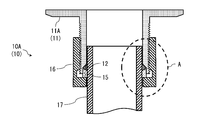
- FIG. 2 is an enlarged cross-sectional view of part A in FIG. 2, which shows an enlarged view of the vacuum duct joint.
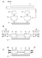
- (A) (B) (C) Explanatory drawing of the construction method of the charged particle accelerator according to another example of 1st Embodiment.
- FIG. 1 is an exploded view of a part of the charged particle accelerator according to the first embodiment of the present invention.
- the joint member 11A which is a part of the charged particle accelerator
- the annular sealing material 12 which is a part of the charged particle accelerator
- the ring member 15 which are inserted into the duct component 17 through which the charged particles pass are inserted. I have.
- a male screw 21 is engraved on the outer peripheral surface, and a contact surface 25 in contact with the annular sealing material 12 is formed at the end of the inner peripheral surface 22.
- a flange plate 18 is formed on the tip end side of the joint member 11A in the first embodiment.
- the ring member 15 is formed with a pressing surface 26 that presses the annular sealing material 12 toward the contact surface 25 of the joint member 11A.
- the nut member 16 has a contact surface 28 that abuts on the ring member 15, and a female screw 27 that is screwed with the male screw 21 of the joint member 11A is engraved on the inner peripheral surface.
- FIG. 2 is an assembly diagram of a part of the charged particle accelerator according to the first embodiment.
- the vacuum duct joint portion 10A provided at the end of the duct component 17 is butted against the flange plates 18 (FIG. 1) of the two opposing joint members 11A, and fastened with screws or the like.
- a sealing material (not shown) such as a gasket or an O-ring for ensuring the internal sealing property is arranged on the butt surface of the flange plate 18.
- FIG. 3 is an enlarged cross-sectional view of the broken line portion A of the vacuum duct joint portion 10 (FIG. 2).
- a clearance 31 is formed between the duct component 17 and the joint member 11.
- a clearance 31 is also formed between the duct component 17 and the nut member 16. The clearance 31 allows the duct component 17 to tilt with respect to the joint member 11.
- the inner diameter of the joint member 11 has a dimensional margin larger than the outer diameter of the duct component 17 to be inserted.
- the contact surface 25 (FIG. 1) formed at the end of the joint member 11 has an inner peripheral surface 22 whose inner peripheral surface 22 is expanded to the extent that the outer peripheral surface of the ring member 15 is engaged, and the surface to which the annular sealing material 12 is in close contact is a surface. It is formed in a tapered shape.
- the inner diameter of the ring member 15 has a dimensional margin larger than the outer diameter of the duct component 17 through which the ring member 15 is inserted, and the end face to which the annular sealing material 12 is in close contact is formed in a tapered shape.
- the ring member 15 has a smooth surface having an end surface that comes into contact with the contact surface 28 (FIG. 1) of the nut member 16 so as not to rotate with the nut member 16 when rotating.
- the annular sealing material 12 is elastically deformed by receiving a pressing force, and an O-ring or the like that adheres to the contact surface and exhibits airtightness is used.
- the annular sealing material 12 receives a pressing force from the end of the joint member 11, the end surface of the ring member 15, and the outer peripheral surface of the duct component 17.
- the elastically deformed annular sealing material 12 seals the intrusion route of the outside air along the outer peripheral surface of the duct component 17 and maintains the degree of vacuum inside the duct component 17. Further, in the clearance 31, even if the duct component 17 is inclined with respect to the joint member 11, the elastic deformation of the annular sealing material 12 follows, so that the airtightness is not impaired. For this reason, misalignment during construction is generally absorbed by installing a bellows, but in each embodiment, it can be absorbed without such a bellows.
- the charged particle accelerator 30A includes a device 35 that interacts with charged particles that pass through the duct component 17 and a support member 36 that supports the device 35 with respect to a floor surface (not shown).
- the device 35 that interacts with the passing charged particles include, but are not limited to, a deflection electromagnet, a quadrupole electromagnet, and a screen monitor.
- the duct component 17 is inserted into the device 35.
- the nut member 16, the ring member 15, the annular sealing material 12, and the joint member 11A are inserted in this order from the tip of the duct component 17.
- the male screw 21 (FIG. 1) of the joint member 11A and the female screw 27 (FIG. 1) of the nut member 16 are screwed together.
- FIG. 4C the assembly of the vacuum duct joint portion 10A is completed.
- FIG. 5 (A), (B), and (C) are explanatory views of a construction method of the charged particle accelerator 30B according to another example of the first embodiment.
- the duct component 17 may be inserted through the plurality of devices 35.
- the construction method of the charged particle accelerator 30B conforms to the construction method of the charged particle accelerator 30A described above, and thus the description thereof will be omitted.
- FIG. 6 is an exploded view of a part of the charged particle accelerator according to the second embodiment of the present invention.
- FIG. 7 is an assembly drawing of a part of the charged particle accelerator according to the second embodiment.
- the joint member 11B which is a part of the charged particle accelerator
- the joint member 11B the annular sealing material 12, the ring member 15, and the nut member 16 which are inserted into the duct component 17 through which the charged particles pass are inserted. I have.
- a male screw 21 is engraved on the outer peripheral surface, and a contact surface 25 in contact with the annular sealing material 12 is formed at the end of the inner peripheral surface 22.
- the joint member 11B according to the second embodiment has contact surfaces 25 formed at both ends in contact with the annular sealing material 12, and the male screw 21 engraved on the outer peripheral surface has two nut members 16 screwed at both ends. ..
- the ring member 15 is formed with a pressing surface 26 that presses the annular sealing material 12 toward the contact surface 25 of the joint member 11B.
- the nut member 16 has a contact surface 28 that abuts on the ring member 15, and a female screw 27 that is screwed with the male screw 21 of the joint member 11 is engraved on the inner peripheral surface.
- the charged particle accelerator 30C has a device 35 that interacts with charged particles passing through the duct component 17 and a support member 36 that supports the device 35 with respect to the floor surface (not shown). I have.
- the duct component 17 is inserted into the device 35.
- the nut member 16, the ring member 15, the annular sealing material 12, and the joint member 11B are inserted in this order from the tip of the duct component 17.
- Two duct parts 17 facing each other are inserted at both ends of the joint member 11B.
- the male screw 21 (FIG. 6) of the joint member 11B and the female screw 27 (FIG. 6) of the nut member 16 are screwed together.
- the assembly of the vacuum duct joint portion 10B is completed as shown in FIGS. 7 and 8 (C).
- the duct component 17 when the duct component 17 is inserted into the device 35 such as an electromagnet, it is necessary to disassemble the device 35 or perform the flange welding work. Is gone. Further, at the construction site, a vacuum duct can be installed after the equipment 35 is installed, and the degree of freedom of construction can be increased.
- the charged particle accelerator of at least one embodiment described above it is possible to simplify the assembly work by configuring the tip of the duct component with a joint member, an annular sealing material, a ring member, and a nut member. Become.
Landscapes
- Engineering & Computer Science (AREA)
- General Engineering & Computer Science (AREA)
- Mechanical Engineering (AREA)
- Physics & Mathematics (AREA)
- Plasma & Fusion (AREA)
- Spectroscopy & Molecular Physics (AREA)
- Particle Accelerators (AREA)
- Joints With Pressure Members (AREA)
Abstract
組み立て作業を簡略化することができる荷電粒子加速器及びその施工方法を提供する。 真空ダクト接合部(10)において、継手部材(11)は雄螺子(21)が外周面に刻設され環状シール材(12)に接触する接触面(25)が内周面(22)の末端に形成されており、リング部材(15)は継手部材(11A)の接触面(25)に向かって環状シール材(12)を押圧する押圧面(26)が形成されており、ナット部材(16)はリング部材(15)に当接する当接面(28)が形成され継手部材(11A)の雄螺子(21)と螺合する雌螺子(27)が内周面に刻設されている。
Description
本発明の実施形態は、荷電粒子加速器及びその施工方法に関する。
加速器は、複数のダクト部品の両端を継手部材で相互接続した真空ダクトにより、荷電粒子の軌道が形成されている。そして、この真空ダクトに沿って偏向電磁石、四極電磁石、スクリーンモニターといった複数の機器が設置され、この真空ダクトの内部空間を運動する荷電粒子の軌道が制御される。そして、従来における加速器の真空ダクトを構成する継手部材は、ダクト部品の両端部に溶接されたフランジ体であった。
従来においては、各種機器を組み込むダクト部品を相互接続するにあたり、次のような工程を経ることが不可避であった。すなわち、工場又は現地で電磁石等の機器を分解し、フランジ付のダクト部品を設置し、再組立後に出荷する工程である。もしくは、現地に電磁石等の機器を設置し、一端のみにフランジを有するダクト部品を機器に挿入後、反対端にフランジ体を溶接する工程である。このため工場及び現地において、加速器の真空ダクトを組み立てる際には、多くの作業を要していた。
本発明はこのような事情を考慮してなされたもので、組み立て作業を簡略化することができる荷電粒子加速器及びその施工方法を提供することを目的とする。
(第1実施形態)
以下、本発明の実施形態を添付図面に基づいて説明する。図1は本発明の第1実施形態に係る荷電粒子加速器の一部分の分解図である。このように荷電粒子加速器は、その一部分である真空ダクト接合部10A(10)において、荷電粒子が通過するダクト部品17に挿通する継手部材11A、環状シール材12、リング部材15、ナット部材16を備えている。
以下、本発明の実施形態を添付図面に基づいて説明する。図1は本発明の第1実施形態に係る荷電粒子加速器の一部分の分解図である。このように荷電粒子加速器は、その一部分である真空ダクト接合部10A(10)において、荷電粒子が通過するダクト部品17に挿通する継手部材11A、環状シール材12、リング部材15、ナット部材16を備えている。
継手部材11Aは、雄螺子21が外周面に刻設され、環状シール材12に接触する接触面25が内周面22の末端に形成されている。そして第1実施形態における継手部材11Aの先端側にはフランジ板18が形成されている。リング部材15は、継手部材11Aの接触面25に向かって環状シール材12を押圧する押圧面26が形成されている。ナット部材16は、リング部材15に当接する当接面28が形成され、継手部材11Aの雄螺子21と螺合する雌螺子27が内周面に刻設されている。
図2は第1実施形態に係る荷電粒子加速器の一部分の組立図である。このようにダクト部品17の末端に設けられた真空ダクト接合部10Aを、二つの対向する継手部材11Aのフランジ板18(図1)同士で突合せ、ネジ等で締結する。なお、フランジ板18の突合せ面には、内部の密封性を確保するためのガスケットやOリングなどのシール材(図示略)が配置されている。このようにして複数のダクト部品17を繋ぐことにより、運動する荷電粒子の軌道となる真空ダクトが形成される。
図3は真空ダクト接合部10(図2)の破線部分A部の拡大断面図である。このようにダクト部品17と継手部材11との間にはクリアランス31が形成されている。そして、ダクト部品17とナット部材16との間にもクリアランス31が形成されている。そしてこのクリアランス31により、継手部材11に対するダクト部品17の傾斜が許容される。
継手部材11の内径は、挿通するダクト部品17の外径よりも寸法余裕を有している。そして、継手部材11の末端に形成された接触面25(図1)は、リング部材15の外周が係合する程度に内周面22が拡径され、さらに環状シール材12が密着する面はテーパ状に形成されている。そして、リング部材15の内径は挿通するダクト部品17の外径よりも寸法余裕を有し、さらに環状シール材12が密着する端面は、テーパ状に形成されている。さらにリング部材15は、ナット部材16の回転時に連れ回りしない程度に、ナット部材16の当接面28(図1)に当接する端面が、滑面に形成されている。
環状シール材12は、押圧力を受けて弾性変形し、接触面に密着して密閉性を発揮するOリング等が用いられる。継手部材11がナット部材16に螺入することにより、環状シール材12は、継手部材11の末端とリング部材15の端面とダクト部品17の外周面とから押圧力を受ける。弾性変形した環状シール材12は、ダクト部品17の外周面に沿う外気の侵入ルートを密閉し、ダクト部品17内部の真空度を維持する。また、クリアランス31において、ダクト部品17が継手部材11に対し傾斜しても、環状シール材12の弾性変形が追従するので、密閉性が損なわれない。このため施工時の位置ずれ等は、一般にベローズを設置して吸収するが、各実施形態においては、そのようなベローズ無しで吸収することができる。
図4(A)(B)(C)は、第1実施形態に係る荷電粒子加速器30Aの施工方法の説明図である。図4に示されるように荷電粒子加速器30Aは、ダクト部品17を通過する荷電粒子と相互作用する機器35と、この機器35を床面(図示略)に対して支持する支持部材36と、を備えている。なお、通過する荷電粒子と相互作用する機器35としては、偏向電磁石、四極電磁石、スクリーンモニターが例示されるが、これらに限定されるものではない。
そして第1実施形態に係る荷電粒子加速器30Aの施工方法は、図4(A)に示すように、機器35にダクト部品17を挿通させる。そして図4(B)に示すように、ナット部材16、リング部材15、環状シール材12、継手部材11Aをこの順番で、ダクト部品17の先端から挿入する。さらに、継手部材11Aの雄螺子21(図1)とナット部材16の雌螺子27(図1)とを螺合させる。これにより、図4(C)に示すように真空ダクト接合部10Aの組み立てが終了する。
図5(A)(B)(C)は、第1実施形態の他の例に係る荷電粒子加速器30Bの施工方法の説明図である。このように、複数の機器35にダクト部品17を挿通させる場合がある。この荷電粒子加速器30Bの施工方法は、上述した荷電粒子加速器30Aの施工方法に準ずるので説明を省略する。
(第2実施形態)
次に図6から図8を参照して本発明における第2実施形態について説明する。なお、図6から図8において図1から図5と共通の構成又は機能を有する部分は、同一符号で示し、重複する説明を省略する。図6は本発明の第2実施形態に係る荷電粒子加速器の一部分の分解図である。図7は第2実施形態に係る荷電粒子加速器の一部分の組立図である。
次に図6から図8を参照して本発明における第2実施形態について説明する。なお、図6から図8において図1から図5と共通の構成又は機能を有する部分は、同一符号で示し、重複する説明を省略する。図6は本発明の第2実施形態に係る荷電粒子加速器の一部分の分解図である。図7は第2実施形態に係る荷電粒子加速器の一部分の組立図である。
このように荷電粒子加速器は、その一部分である真空ダクト接合部10B(10)において、荷電粒子が通過するダクト部品17に挿通する継手部材11B、環状シール材12、リング部材15、ナット部材16を備えている。
継手部材11Bは、雄螺子21が外周面に刻設され、環状シール材12に接触する接触面25が内周面22の末端に形成されている。そして第2実施形態における継手部材11Bは、環状シール材12に接触する接触面25が両端に形成され、外周面に刻設された雄螺子21は、両端に二つのナット部材16が螺合する。リング部材15は、継手部材11Bの接触面25に向かって環状シール材12を押圧する押圧面26が形成されている。ナット部材16は、リング部材15に当接する当接面28が形成され、継手部材11の雄螺子21と螺合する雌螺子27が内周面に刻設されている。
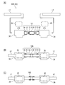
図8(A)(B)(C)は、第2実施形態に係る荷電粒子加速器30Cの施工方法の説明図である。図8に示されるように荷電粒子加速器30Cは、ダクト部品17を通過する荷電粒子と相互作用する機器35と、この機器35を床面(図示略)に対して支持する支持部材36と、を備えている。
そして第2実施形態に係る荷電粒子加速器30Cの施工方法は、図8(A)に示すように、機器35にダクト部品17を挿通させる。そして図8(B)に示すように、ナット部材16、リング部材15、環状シール材12、継手部材11Bをこの順番で、ダクト部品17の先端から挿入する。なお継手部材11Bの両端には、対向する二つのダクト部品17が挿入されている。さらに、継手部材11Bの雄螺子21(図6)とナット部材16の雌螺子27(図6)とを螺合させる。これにより、図7および図8(C)に示すように真空ダクト接合部10Bの組み立てが終了する。
このように、各実施形態に係る荷電粒子加速器30の施工方法によれば、ダクト部品17を電磁石等の機器35に挿通させるに当たり、機器35を分解したりフランジの溶接作業を実施したりする必要がなくなる。さらに、施工現場において、機器35を設置した後に、真空ダクトを施設することができ、工事の自由度を高めることができる。
以上述べた少なくともひとつの実施形態の荷電粒子加速器によれば、ダクト部品の先端を、継手部材、環状シール材、リング部材、ナット部材で構成することにより、組み立て作業を簡略化することが可能となる。
本発明のいくつかの実施形態を説明したが、これらの実施形態は、例として提示したものであり、発明の範囲を限定することは意図していない。これら実施形態は、その他の様々な形態で実施されることが可能であり、発明の要旨を逸脱しない範囲で、種々の省略、置き換え、変更、組み合わせを行うことができる。これら実施形態やその変形は、発明の範囲や要旨に含まれると同様に、特許請求の範囲に記載された発明とその均等の範囲に含まれるものである。
Claims (6)
- 荷電粒子が通過するダクト部品に挿通する継手部材、環状シール材、リング部材、ナット部材を備え、
前記継手部材は、雄螺子が外周面に刻設され、前記環状シール材に接触する接触面が内周面の末端に形成され、
前記リング部材は、前記継手部材の前記接触面に向かって前記環状シール材を押圧する押圧面が形成され、
前記ナット部材は、前記リング部材に当接する当接面が形成され、前記継手部材の雄螺子と螺合する雌螺子が内周面に刻設されている荷電粒子加速器。 - 請求項1に記載の荷電粒子加速器において、
前記継手部材は、先端側にフランジ板が形成されている荷電粒子加速器。 - 請求項1に記載の荷電粒子加速器において、
前記継手部材は、
前記環状シール材に接触する前記接触面が両端に形成され、
前記外周面に刻設された前記雄螺子は、両端に二つの前記ナット部材が螺合する荷電粒子加速器。 - 請求項1から請求項3のいずれか1項に記載の荷電粒子加速器において、
前記ダクト部品と前記継手部材とにより形成されるクリアランスと、前記ダクト部品と前記ナット部材とにより形成されるクリアランスとは、前記継手部材に対する前記ダクト部品の傾斜を許容するものである荷電粒子加速器。 - 請求項1から請求項4のいずれか1項に記載の荷電粒子加速器において、
前記ダクト部品を通過する前記荷電粒子と相互作用する機器と、
前記機器を床面に対して支持する支持部材と、を備える荷電粒子加速器。 - 請求項5に記載の荷電粒子加速器の施工方法であって、
前記機器に前記ダクト部品を挿通させるステップと、
前記ナット部材、前記リング部材、前記環状シール材、前記継手部材をこの順番で、前記ダクト部品の先端から挿入するステップと、
前記継手部材の前記雄螺子と前記ナット部材の前記雌螺子とを螺合させるステップと、を含む荷電粒子加速器の施工方法。
Priority Applications (3)
| Application Number | Priority Date | Filing Date | Title |
|---|---|---|---|
| CN202080017801.2A CN113692782A (zh) | 2019-04-15 | 2020-04-13 | 带电粒子加速器及其施工方法 |
| KR1020217024663A KR102616005B1 (ko) | 2019-04-15 | 2020-04-13 | 하전 입자 가속기 및 그 시공 방법 |
| US17/470,345 US12188583B2 (en) | 2019-04-15 | 2021-09-09 | Charged particle accelerator and method for building charged particle accelerator |
Applications Claiming Priority (2)
| Application Number | Priority Date | Filing Date | Title |
|---|---|---|---|
| JP2019-077344 | 2019-04-15 | ||
| JP2019077344A JP7163241B2 (ja) | 2019-04-15 | 2019-04-15 | 荷電粒子加速器及びその施工方法 |
Related Child Applications (1)
| Application Number | Title | Priority Date | Filing Date |
|---|---|---|---|
| US17/470,345 Continuation US12188583B2 (en) | 2019-04-15 | 2021-09-09 | Charged particle accelerator and method for building charged particle accelerator |
Publications (1)
| Publication Number | Publication Date |
|---|---|
| WO2020213552A1 true WO2020213552A1 (ja) | 2020-10-22 |
Family
ID=72837900
Family Applications (1)
| Application Number | Title | Priority Date | Filing Date |
|---|---|---|---|
| PCT/JP2020/016247 Ceased WO2020213552A1 (ja) | 2019-04-15 | 2020-04-13 | 荷電粒子加速器及びその施工方法 |
Country Status (5)
| Country | Link |
|---|---|
| US (1) | US12188583B2 (ja) |
| JP (1) | JP7163241B2 (ja) |
| KR (1) | KR102616005B1 (ja) |
| CN (1) | CN113692782A (ja) |
| WO (1) | WO2020213552A1 (ja) |
Citations (5)
| Publication number | Priority date | Publication date | Assignee | Title |
|---|---|---|---|---|
| JPH0557380A (ja) * | 1991-09-02 | 1993-03-09 | Eagle Ind Co Ltd | 荷電粒子加速装置の真空ダクト用ダクト単管の製造方法 |
| JPH0850999A (ja) * | 1994-08-05 | 1996-02-20 | Toshiba Corp | ビームダクト |
| JPH08326968A (ja) * | 1995-05-31 | 1996-12-10 | Takashige Sangyo Kk | 絶縁パイプコネクター |
| JP2002130563A (ja) * | 2000-10-20 | 2002-05-09 | Tokyo Gas Co Ltd | 管用継手 |
| US20130294557A1 (en) * | 2010-11-11 | 2013-11-07 | Schlumberger Technology Corporation | Particle Accelerator With A Heat Pipe Supporting Components Of A High Voltage Power Supply |
Family Cites Families (17)
| Publication number | Priority date | Publication date | Assignee | Title |
|---|---|---|---|---|
| US2405822A (en) * | 1943-02-26 | 1946-08-13 | Imp Brass Mfg Co | Sealed flexible coupling |
| US2523135A (en) * | 1946-03-07 | 1950-09-19 | Mercier Jean | Coupling |
| US3275350A (en) * | 1964-06-25 | 1966-09-27 | Imp Eastman Corp | Fitting |
| US3265414A (en) * | 1964-07-10 | 1966-08-09 | Reid | Sealed pipe joint |
| JPH05217694A (ja) * | 1992-02-03 | 1993-08-27 | Toshiba Corp | 粒子加速器 |
| JPH07111197A (ja) * | 1993-10-13 | 1995-04-25 | Ishikawajima Harima Heavy Ind Co Ltd | 粒子加速器における真空チャンバーの接続構造 |
| JPH0854087A (ja) * | 1994-08-09 | 1996-02-27 | Riken Corp | メカニカル形管継手 |
| JP3236175B2 (ja) | 1994-10-20 | 2001-12-10 | 日立造船株式会社 | 真空ダクト用フランジ |
| JPH09199298A (ja) * | 1996-01-22 | 1997-07-31 | Ishikawajima Harima Heavy Ind Co Ltd | 真空チェンバ |
| JPH1073186A (ja) * | 1996-08-29 | 1998-03-17 | Benkan Corp | 薄肉ステンレス鋼管と管継手との接続機構 |
| JPH10318461A (ja) * | 1997-05-16 | 1998-12-04 | Kvk Corp | 配管の接続構造 |
| KR100318461B1 (ko) | 1998-10-13 | 2002-02-19 | 박종섭 | 반도체소자의분리방법 |
| JP2015007445A (ja) * | 2013-06-25 | 2015-01-15 | 井上スダレ株式会社 | 管継手構造 |
| KR101621758B1 (ko) * | 2016-01-29 | 2016-05-17 | 비케이엠 주식회사 | 반도체 제조설비의 드레인 배관용 연결 조인트 |
| CN106163075B (zh) * | 2016-07-14 | 2018-04-13 | 中国科学院上海光学精密机械研究所 | 一种充气型放电毛细管的夹持装置 |
| KR101956148B1 (ko) * | 2016-11-29 | 2019-03-11 | 주식회사 다원시스 | 가속기 빔 수송계 구성용 탈 부착식 진공 파이프-플랜지 세트 및 연결 방법 |
| US20210018120A1 (en) * | 2019-07-19 | 2021-01-21 | Olab S.R.L. | Compression-type fitting for connecting pipes to hydraulic or pneumatic components or for connecting pipes together, particularly for refrigeration systems |
-
2019
- 2019-04-15 JP JP2019077344A patent/JP7163241B2/ja active Active
-
2020
- 2020-04-13 KR KR1020217024663A patent/KR102616005B1/ko active Active
- 2020-04-13 WO PCT/JP2020/016247 patent/WO2020213552A1/ja not_active Ceased
- 2020-04-13 CN CN202080017801.2A patent/CN113692782A/zh active Pending
-
2021
- 2021-09-09 US US17/470,345 patent/US12188583B2/en active Active
Patent Citations (5)
| Publication number | Priority date | Publication date | Assignee | Title |
|---|---|---|---|---|
| JPH0557380A (ja) * | 1991-09-02 | 1993-03-09 | Eagle Ind Co Ltd | 荷電粒子加速装置の真空ダクト用ダクト単管の製造方法 |
| JPH0850999A (ja) * | 1994-08-05 | 1996-02-20 | Toshiba Corp | ビームダクト |
| JPH08326968A (ja) * | 1995-05-31 | 1996-12-10 | Takashige Sangyo Kk | 絶縁パイプコネクター |
| JP2002130563A (ja) * | 2000-10-20 | 2002-05-09 | Tokyo Gas Co Ltd | 管用継手 |
| US20130294557A1 (en) * | 2010-11-11 | 2013-11-07 | Schlumberger Technology Corporation | Particle Accelerator With A Heat Pipe Supporting Components Of A High Voltage Power Supply |
Also Published As
| Publication number | Publication date |
|---|---|
| JP7163241B2 (ja) | 2022-10-31 |
| US20210404580A1 (en) | 2021-12-30 |
| US12188583B2 (en) | 2025-01-07 |
| JP2020177738A (ja) | 2020-10-29 |
| KR20210109618A (ko) | 2021-09-06 |
| KR102616005B1 (ko) | 2023-12-21 |
| CN113692782A (zh) | 2021-11-23 |
Similar Documents
| Publication | Publication Date | Title |
|---|---|---|
| CN100507336C (zh) | 管接头 | |
| US8235828B2 (en) | Diaphragm couplings | |
| JP5026898B2 (ja) | タービンシェル組立体を位置合せしかつシールするためのシステム及び方法 | |
| EP1582799A1 (en) | Pipe joint | |
| US5700014A (en) | Vacuum sealing structure | |
| JPH0689871B2 (ja) | 2本の剛直固定管を接続する密閉型継手 | |
| KR101915492B1 (ko) | 무용접 조립식 배관 플랜지 연결구 | |
| EP1085247B1 (en) | Seal rings for low loss flexible coupling of gas conduits | |
| US12188583B2 (en) | Charged particle accelerator and method for building charged particle accelerator | |
| JP2019019867A (ja) | 漏洩防止装置 | |
| US7566080B2 (en) | Systems and methods for coupling conduits of dissimilar materials which are subject to large temperature variations | |
| JP2016205566A (ja) | 無溶接フランジ管継手 | |
| US5421624A (en) | Flange joint assembly | |
| WO2019082466A1 (ja) | 管継手および管継手の組付方法 | |
| CN111520473A (zh) | 一种复合材料飞机油箱口盖密封结构及密封方法 | |
| KR20030085025A (ko) | 관 모양의 부품을 위한 연결 플랜지 | |
| US8172279B2 (en) | Method for manufacturing a flanged element and a flanged element | |
| TWI409898B (zh) | 真空腔室間的密封 | |
| CN104121365A (zh) | 密封装置及密封方法 | |
| JP4882827B2 (ja) | 配管の継手構造 | |
| JPH0729355Y2 (ja) | 管継手 | |
| KR20180060645A (ko) | 가속기 빔 수송계 구성용 탈 부착식 진공 파이프-플랜지 세트 및 연결 방법 | |
| JP4784864B2 (ja) | パネルケーシング | |
| JPH08312341A (ja) | 自動車用排気系の継手装置 | |
| US4711475A (en) | High pressure fitting |
Legal Events
| Date | Code | Title | Description |
|---|---|---|---|
| 121 | Ep: the epo has been informed by wipo that ep was designated in this application |
Ref document number: 20790466 Country of ref document: EP Kind code of ref document: A1 |
|
| ENP | Entry into the national phase |
Ref document number: 20217024663 Country of ref document: KR Kind code of ref document: A |
|
| NENP | Non-entry into the national phase |
Ref country code: DE |
|
| 122 | Ep: pct application non-entry in european phase |
Ref document number: 20790466 Country of ref document: EP Kind code of ref document: A1 |