WO2020213504A1 - 油圧装置用作動油及びその油圧装置用作動油を用いた油圧装置 - Google Patents
油圧装置用作動油及びその油圧装置用作動油を用いた油圧装置 Download PDFInfo
- Publication number
- WO2020213504A1 WO2020213504A1 PCT/JP2020/015893 JP2020015893W WO2020213504A1 WO 2020213504 A1 WO2020213504 A1 WO 2020213504A1 JP 2020015893 W JP2020015893 W JP 2020015893W WO 2020213504 A1 WO2020213504 A1 WO 2020213504A1
- Authority
- WO
- WIPO (PCT)
- Prior art keywords
- group
- hydraulic
- ester compound
- compound
- oil
- Prior art date
- Legal status (The legal status is an assumption and is not a legal conclusion. Google has not performed a legal analysis and makes no representation as to the accuracy of the status listed.)
- Ceased
Links
Images
Classifications
-
- C—CHEMISTRY; METALLURGY
- C10—PETROLEUM, GAS OR COKE INDUSTRIES; TECHNICAL GASES CONTAINING CARBON MONOXIDE; FUELS; LUBRICANTS; PEAT
- C10M—LUBRICATING COMPOSITIONS; USE OF CHEMICAL SUBSTANCES EITHER ALONE OR AS LUBRICATING INGREDIENTS IN A LUBRICATING COMPOSITION
- C10M129/00—Lubricating compositions characterised by the additive being an organic non-macromolecular compound containing oxygen
- C10M129/02—Lubricating compositions characterised by the additive being an organic non-macromolecular compound containing oxygen having a carbon chain of less than 30 atoms
- C10M129/16—Ethers
- C10M129/18—Epoxides
-
- C—CHEMISTRY; METALLURGY
- C10—PETROLEUM, GAS OR COKE INDUSTRIES; TECHNICAL GASES CONTAINING CARBON MONOXIDE; FUELS; LUBRICANTS; PEAT
- C10M—LUBRICATING COMPOSITIONS; USE OF CHEMICAL SUBSTANCES EITHER ALONE OR AS LUBRICATING INGREDIENTS IN A LUBRICATING COMPOSITION
- C10M133/00—Lubricating compositions characterised by the additive being an organic non-macromolecular compound containing nitrogen
- C10M133/02—Lubricating compositions characterised by the additive being an organic non-macromolecular compound containing nitrogen having a carbon chain of less than 30 atoms
- C10M133/04—Amines, e.g. polyalkylene polyamines; Quaternary amines
- C10M133/06—Amines, e.g. polyalkylene polyamines; Quaternary amines having amino groups bound to acyclic or cycloaliphatic carbon atoms
-
- C—CHEMISTRY; METALLURGY
- C10—PETROLEUM, GAS OR COKE INDUSTRIES; TECHNICAL GASES CONTAINING CARBON MONOXIDE; FUELS; LUBRICANTS; PEAT
- C10M—LUBRICATING COMPOSITIONS; USE OF CHEMICAL SUBSTANCES EITHER ALONE OR AS LUBRICATING INGREDIENTS IN A LUBRICATING COMPOSITION
- C10M137/00—Lubricating compositions characterised by the additive being an organic non-macromolecular compound containing phosphorus
- C10M137/02—Lubricating compositions characterised by the additive being an organic non-macromolecular compound containing phosphorus having no phosphorus-to-carbon bond
- C10M137/04—Phosphate esters
-
- C—CHEMISTRY; METALLURGY
- C10—PETROLEUM, GAS OR COKE INDUSTRIES; TECHNICAL GASES CONTAINING CARBON MONOXIDE; FUELS; LUBRICANTS; PEAT
- C10M—LUBRICATING COMPOSITIONS; USE OF CHEMICAL SUBSTANCES EITHER ALONE OR AS LUBRICATING INGREDIENTS IN A LUBRICATING COMPOSITION
- C10M141/00—Lubricating compositions characterised by the additive being a mixture of two or more compounds covered by more than one of the main groups C10M125/00 - C10M139/00, each of these compounds being essential
- C10M141/10—Lubricating compositions characterised by the additive being a mixture of two or more compounds covered by more than one of the main groups C10M125/00 - C10M139/00, each of these compounds being essential at least one of them being an organic phosphorus-containing compound
-
- C—CHEMISTRY; METALLURGY
- C10—PETROLEUM, GAS OR COKE INDUSTRIES; TECHNICAL GASES CONTAINING CARBON MONOXIDE; FUELS; LUBRICANTS; PEAT
- C10M—LUBRICATING COMPOSITIONS; USE OF CHEMICAL SUBSTANCES EITHER ALONE OR AS LUBRICATING INGREDIENTS IN A LUBRICATING COMPOSITION
- C10M169/00—Lubricating compositions characterised by containing as components a mixture of at least two types of ingredient selected from base-materials, thickeners or additives, covered by the preceding groups, each of these compounds being essential
- C10M169/04—Mixtures of base-materials and additives
-
- F—MECHANICAL ENGINEERING; LIGHTING; HEATING; WEAPONS; BLASTING
- F16—ENGINEERING ELEMENTS AND UNITS; GENERAL MEASURES FOR PRODUCING AND MAINTAINING EFFECTIVE FUNCTIONING OF MACHINES OR INSTALLATIONS; THERMAL INSULATION IN GENERAL
- F16F—SPRINGS; SHOCK-ABSORBERS; MEANS FOR DAMPING VIBRATION
- F16F9/00—Springs, vibration-dampers, shock-absorbers, or similarly-constructed movement-dampers using a fluid or the equivalent as damping medium
- F16F9/10—Springs, vibration-dampers, shock-absorbers, or similarly-constructed movement-dampers using a fluid or the equivalent as damping medium using liquid only; using a fluid of which the nature is immaterial
- F16F9/14—Devices with one or more members, e.g. pistons, vanes, moving to and fro in chambers and using throttling effect
- F16F9/16—Devices with one or more members, e.g. pistons, vanes, moving to and fro in chambers and using throttling effect involving only straight-line movement of the effective parts
- F16F9/18—Devices with one or more members, e.g. pistons, vanes, moving to and fro in chambers and using throttling effect involving only straight-line movement of the effective parts with a closed cylinder and a piston separating two or more working spaces therein
-
- F—MECHANICAL ENGINEERING; LIGHTING; HEATING; WEAPONS; BLASTING
- F16—ENGINEERING ELEMENTS AND UNITS; GENERAL MEASURES FOR PRODUCING AND MAINTAINING EFFECTIVE FUNCTIONING OF MACHINES OR INSTALLATIONS; THERMAL INSULATION IN GENERAL
- F16F—SPRINGS; SHOCK-ABSORBERS; MEANS FOR DAMPING VIBRATION
- F16F9/00—Springs, vibration-dampers, shock-absorbers, or similarly-constructed movement-dampers using a fluid or the equivalent as damping medium
- F16F9/32—Details
Definitions
- the present invention relates to a hydraulic oil for a hydraulic system and a hydraulic system using the hydraulic oil for the hydraulic system.
- the oil seal is arranged so as to be in constant contact with the piston rod, and plays a role of preventing the hydraulic oil from flowing out from the inside of the hydraulic system.
- the oil seal is made of a rubber-based material
- the contact surface with the piston rod surface made of metal has a large coefficient of friction. Therefore, when the piston rod reciprocates in the hydraulic system, a large frictional force is generated between the oil seal and the piston rod.
- Patent Document 1 discloses a lubricating oil composition that exhibits a friction reducing effect by blending a specific sulfur-containing compound and a specific polar group-containing compound in the base oil.
- a specific sulfur-containing compound a specific sulfur-containing compound
- a specific polar group-containing compound a compound having at least one polar group selected from an amino group, an amide group and a hydroxyl group and an alkyl group having 3 to 24 carbon atoms is disclosed.
- Patent Document 1 discloses that a substance containing a phosphoric acid ester compound and a phosphite ester compound can be added as an abrasion resistant agent or an extreme pressure agent.
- the coefficient of friction between the oil seal and the piston rod is arbitrarily reduced by the phosphate ester compound and the phosphite ester compound blended in the hydraulic oil of the shock absorber for automobiles, and the ride comfort is achieved. Can be adjusted.
- the coefficient of friction described above is adjusted to be slightly higher when, for example, steerability is important, and lower when riding comfort is important.
- the phosphoric acid ester compound and the phosphite ester compound are excellent in the ability to adjust the coefficient of friction, they are easily deactivated due to aged deterioration.
- the hydraulic oil contained in an automobile shock absorber continues to be used from the time of automobile manufacturing to the time of automobile disposal without being replaced even once.
- the present invention uses a hydraulic oil for a hydraulic device such as a shock absorber for automobiles in which each component is stably present for a long period of time and the fluctuation of the friction coefficient due to long-term use is small, and the hydraulic oil thereof. It is an object of the present invention to provide a hydraulic system.
- the hydraulic oil for a hydraulic device of the present invention includes a base oil, at least one selected from the group consisting of a phosphite ester compound and a phosphate ester compound, a primary amine compound, and a glycidyl group or.
- the content of at least one selected from the group consisting of the phosphite ester compound and the phosphate ester compound, which includes a compound having an epoxy group, is the base oil and the phosphite ester compound and the phosphate ester compound.
- the ratio is 30% or more and 500% or less, and the molar ratio of the compound having a glycidyl group or an epoxy group to at least one selected from the group consisting of the phosphite ester compound and the phosphoric acid ester compound is 10% or more and 500%. It is characterized by the following.
- the present invention is a hydraulic device including the above-mentioned hydraulic oil for a hydraulic device.
- This specification includes the disclosure content of Japanese Patent Application No. 2019-080229, which is the basis of the priority of the present application.
- a hydraulic oil for a hydraulic system in which each component exists stably for a long period of time and the coefficient of friction generated between the oil seal and the piston rod can be maintained for a long period of time, and a hydraulic system using the hydraulic oil for the hydraulic system.
- the hydraulic fluid for a hydraulic device includes (A) a base oil, (B) at least one selected from the group consisting of a phosphite ester compound and a phosphate ester compound, and (C) first grade.
- the content of at least one selected from the group consisting of the phosphite ester compound and the phosphate ester compound, which comprises an amine compound and (D) a compound having a glycidyl group or an epoxy group, is the base oil and the above.
- the molar ratio of the primary amine compound to at least one of the compounds is 30% or more and 500% or less, and the glycidyl group or epoxy group is added to at least one selected from the group consisting of the phosphite ester compound and the phosphate ester compound.
- the molar ratio of the compound is 10% or more and 500% or less.
- any material can be selected from the mineral oil-based and / or synthetic oil-based base oils conventionally used as hydraulic oils for hydraulic systems.
- the mineral oil-based base oil include paraffin-based mineral oil and naphthenic mineral oil.
- Examples of synthetic oil-based base oils include polybutene, polypropylene, poly ⁇ -olefin, polyol ester, fatty acid monoester, aromatic monoester, fatty acid diester, aliphatic polybasic acid ester, aromatic polybasic acid ester, and polyol polyester.
- Esters such as phosphoric acid esters, polyalkylene glycols, polyphenyl ethers, polyglycols, alkylbenzenes, synthetic naphthenes, ionic liquids and the like.
- paraffin-based mineral oil paraffin-based mineral oil, naphthen-based mineral oil, poly- ⁇ -olefin, polyphenyl ether, alkylbenzene, synthetic naphthen, silicone, polyalkylene glycol and the like are preferable. Any one of these base oils may be used alone, or two or more thereof may be used in combination.
- the preferred kinematic viscosity of the base oil varies depending on the hydraulic system to which the hydraulic oil for the hydraulic system is applied.
- the kinematic viscosity at 40 ° C. (from the viewpoint of fluidity in a low temperature state)
- the test based on ISO3448: 1992) is preferably in the range of 8 mm 2 / s (cSt) or more and 17 mm 2 / s (cSt) or less.
- At least one selected from the group consisting of a phosphite ester compound and a phosphoric acid ester compound is used.
- the phosphate group and / or the phosphite group releases protons by the catalytic action of the metal exposed on the surface of the piston rod and is adsorbed on the surface of the piston rod to be stable.
- Form an esterified film The thickness of the formed adsorption film depends on the length of the alkyl group of the phosphate ester compound and the phosphite ester compound. By changing the length of the alkyl group, the thickness of the adsorption membrane can be controlled, and the coefficient of friction generated between the piston rod and the oil seal can be arbitrarily adjusted.
- the phosphite ester compound used as the material of the above (B) preferably has a structure represented by the following formula (1).
- one of R 1 and R 2 is hydrogen or a hydrocarbon group having 3 or more and 30 or less carbon atoms, and the other is a hydrocarbon group having 3 or more and 30 or less carbon atoms. From the viewpoint of solubility, it is more preferable that the number of carbon atoms is 3 or more and 18 or less.
- These hydrocarbon groups may be alkyl groups which are saturated hydrocarbon groups, or unsaturated hydrocarbon groups such as alkenyl groups. One may be a saturated hydrocarbon group and the other may be an unsaturated hydrocarbon group.
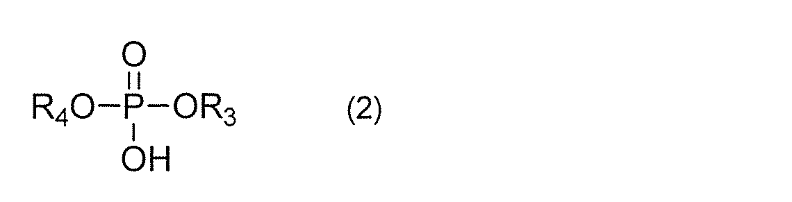
- the phosphoric acid ester compound used as the material of the above (B) preferably has a structure represented by the following formula (2).
- R 3 and R 4 one is hydrogen or a hydrocarbon group having 3 to 30 carbon atoms, the other is a hydrocarbon group having 3 to 30 carbon atoms.
- the above carbon number is more preferably 3 or more and 18 or less.
- These hydrocarbon groups may be alkyl groups which are saturated hydrocarbon groups, or unsaturated hydrocarbon groups such as alkenyl groups. One may be a saturated hydrocarbon group and the other may be an unsaturated hydrocarbon group.
- Examples of the saturated hydrocarbon group in the above phosphite ester compound and phosphoric acid ester compound include alkyl groups such as diethylhexyl group, lauryl group, myristyl group, cetyl group and stearyl group. Further, examples of the unsaturated hydrocarbon group include an oleyl group and the like.
- R 1 , R 2 , R 3 and R 4 may all be the same hydrocarbon group or may be different hydrocarbon groups. Alternatively, some of R 1 , R 2 , R 3 and R 4 may be the same hydrocarbon group, and the others may be composed of different hydrocarbon groups.
- any one of them may be used alone, or a plurality of kinds of the phosphite ester compound and / or the phosphoric acid ester compound may be used. It may be mixed and used.
- phosphite ester compound used as the material of (B) include diethylhexyl hydrogen phosphite, dilauryl hydrogen phosphite, distearyl hydrogen phosphite, dioleyl hydrogen phosphite and the like. In particular, Georail hydrogen phosphite is preferably used.
- the phosphoric acid ester compound used as the material of (B) include ethylhexyl acid phosphate, lauryl acid phosphate, stearyl acid phosphate, and oleyl acid phosphate.
- the blending amount of the material (B) is more preferably 0.3% by mass or more and 5.0% by mass or less with respect to the total of the base oil of (A) and the material of (B).
- the material (B) exerts its effect when it is blended in an amount of more than 0.1% by mass, and exerts a sufficient effect when it is blended in an amount of 0.3% by mass or more. Further, the same effect is exhibited even if the blending amount exceeds 5.0% by mass, but the blending amount is preferably 5.0% by mass or less from the viewpoint of maintaining good solubility in the base oil. ..
- any compound in which one of the hydrogen atoms of ammonia is replaced with a hydrocarbon group or an aromatic group can be applied.
- a compound represented by the following formula (3) is used as the primary amine compound.
- R 5 is a saturated or unsaturated hydrocarbon group having 12 to 30 carbon atoms.
- the carbon number of these hydrocarbon groups is more preferably 12 or more and 22 or less.
- saturated hydrocarbon groups include alkyl groups such as dodecyl group, myristyl group, cetyl group and stearyl group.
- examples of the unsaturated hydrocarbon group include an alkenyl group such as an oleyl group and an elsyl group.
- the phosphite ester compound and the phosphoric acid ester compound which are the materials of the above (B), produce an acidic phosphoric acid ester compound due to deterioration due to long-term use. Since such an acidic phosphoric acid ester compound has high reactivity and attacks the phosphite ester compound and the phosphoric acid ester compound of the above (B), the deterioration of the material of (B) progresses in a chain reaction.
- the primary amine compound (C) prevents the chain deterioration reaction of the material (B) by capturing the acidic phosphoric acid ester compound, and maintains the coefficient of friction between the oil seal and the piston rod for a long period of time. enable.
- the molar ratio of the primary amine compound to the material of (B) is 30% or more and 500% or less, preferably 50% or more and 300% or less.
- the effect is exhibited when the molar ratio of the primary amine compound (C) is 30% or more, and a sufficient effect is exhibited when the compound is blended in the range of 50% or more and 300% or less.
- the same effect is exhibited even if the molar ratio exceeds 300%, but the excessively blended primary amine compound does not sufficiently dissolve in the base oil and has an adverse effect of inhibiting the surface adsorption of the phosphite ester compound. Therefore, the molar ratio is more preferably 300% or less.
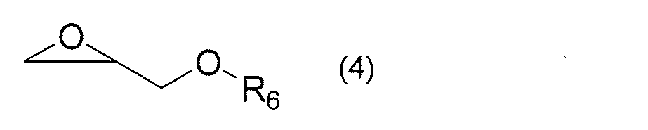
- any compound can be used as the compound having a glycidyl group or an epoxy group as the material of (D), and in particular, the glycidyl ether represented by the following formula (4) is preferably used.
- R 6 is a saturated or unsaturated hydrocarbon group having 3 to 30 carbon atoms.
- the carbon number of these hydrocarbon groups is more preferably 8 or more and 22 or less.
- Examples of such a hydrocarbon group include alkyl groups such as lauryl group, myristyl group, cetyl group and stearyl group.
- an alkenyl group such as an oleyl group and an elsyl group can be mentioned.
- the material of (D) above include butyl glycidyl ether, octyl glycidyl ether, stearyl glycidyl ether and the like. Particularly preferred is octylglycidyl ether.
- the primary amine compound which is the material of (C) traps the acidic phosphoric acid ester compound to cause a chain deterioration reaction of the phosphite ester compound and / or the phosphoric acid ester compound of (B).
- Preventing (B) allows the ability to regulate friction between the oil seal and the piston rod to be maintained for extended periods of time.
- the primary amine compound of (C) has aggression against the phosphite ester compound and / or the phosphate ester compound of (B).
- the decomposition reaction of the above-mentioned (B) phosphite ester compound or phosphoric acid ester compound can be suppressed.
- the acidic phosphoric acid ester compound generated by the deterioration of the (B) phosphite ester compound and / or the phosphoric acid ester compound is captured by the primary amine compound of (C), thereby suppressing the chain deterioration reaction while suppressing the chain deterioration reaction.
- the molar ratio of the compound having a glycidyl group or an epoxy group to the material of (B) is 10% or more and 500% or less, preferably. It is 50% or more and 300% or less.
- the effect is exhibited when the molar ratio of the compound having the glycidyl group or the epoxy group of (D) is 10% or more, and a sufficient effect is exhibited when the compound is blended in an amount of 50% or more. Further, the same effect is exhibited even if the molar ratio exceeds 300%, but the molar ratio is preferably 300% or less from the viewpoint of maintaining good solubility in the base oil.
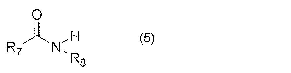
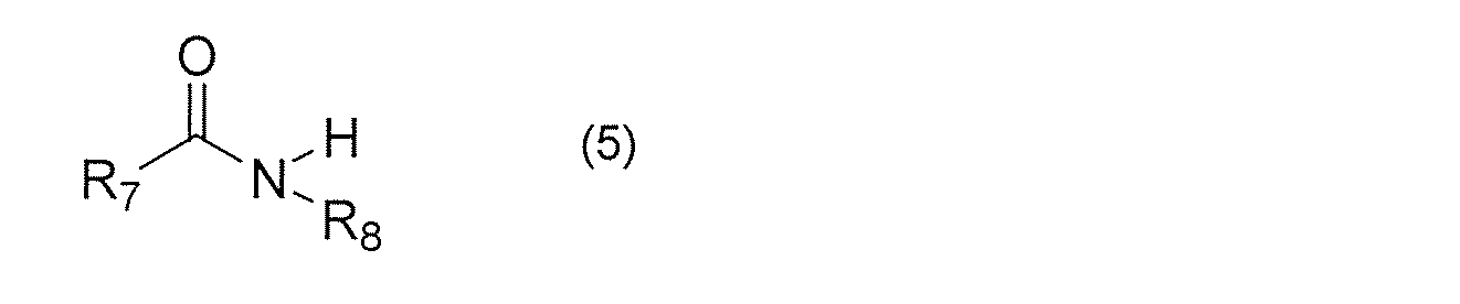
- the hydraulic oil for the hydraulic system according to the present embodiment can further contain a secondary amide compound represented by the following formula (5), if necessary.
- R 7 and R 8 are each independently saturated or unsaturated hydrocarbon group having 8 or more and 24 or less carbon atoms.
- the carbon number of these hydrocarbon groups is more preferably 12 or more and 22 or less.
- saturated hydrocarbon groups include alkyl groups such as dodecyl group, myristyl group, cetyl group and stearyl group.
- examples of the unsaturated hydrocarbon group include an alkenyl group such as an oleyl group and an elsyl group.
- the above secondary amide compound examples include N-stearyl oleic acid amide, N-stearyl erucic acid amide, N-cetyl oleic acid amide, N-cetyl erucic acid amide, N-myristyl oleic acid amide, and N-.
- Examples thereof include myristyl ercylic acid amide, N-dodecyl oleic acid amide, and N-dodecyl ercylic acid amide.
- the total amount of the base oil of (A), at least one selected from the group consisting of the phosphite ester compound of (B) and the phosphoric acid ester, and the secondary amide compound 0.01% by mass or more and 2.0% by mass or less is preferable.
- Additives may be appropriately added to the hydraulic oil for the hydraulic system according to the present embodiment as long as the effect is not impaired.
- Specific additives include wear inhibitors, oiliness improvers, antioxidants, ashless dispersants, metal dispersants, viscosity index improvers, pour point depressants, metal defoamers, and rust preventives. , And antifoaming agents and the like.
- the hydraulic oil for the hydraulic system according to the present embodiment is selected from the group consisting of antioxidants, ashless dispersants, metal dispersants, viscosity index improvers, rust preventives, and defoamers. It is preferable to contain at least one additive to be added.
- anti-wear agent examples include zinc dithiophosphate and its derivatives, sulfur compounds and their derivatives, molybdenum disulfide and its derivatives, and the like.
- oiliness improver examples include fatty alcohols and derivatives thereof, fatty acid esters and derivatives thereof, fatty acids and derivatives thereof, amine compounds and derivatives thereof, and the like.
- antioxidants examples include amine-based antioxidants and their derivatives, phenol-based antioxidants and their derivatives, sulfur-based antioxidants and their derivatives, carbamate-based antioxidants and their derivatives, and the like.
- ashless dispersant examples include succinic acid imide and its derivatives, benzylamine and its derivatives, esters and its derivatives, and the like.
- metal-based dispersant examples include calcium salicylate and its derivatives, calcium phenate and its derivatives, calcium sulfonate and its derivatives, potassium borate and its derivatives, and the like.
- viscosity index improver examples include polymethacrylate and its derivatives, polyisobutylene and its derivatives, olefin copolymers and their derivatives, and the like.
- pour point lowering agent examples include polymethacrylate and its derivative, polybutene and its derivative, polyalkylstyrene and its derivative, and the like.
- metal inactivating agent examples include benzotriazole and its derivatives, thiadiazole and its derivatives, and the like.
- rust preventive examples include imidazole and its derivatives, benzotriazole and its derivatives, thiadiazole and its derivatives, and the like.
- defoaming agent examples include silicone-based defoaming agents and their derivatives, polyacrylate-based defoaming agents and their derivatives, and the like.
- the total amount of these various additives is less than 30% by mass of the total hydraulic oil for the hydraulic system.
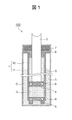
- FIG. 1 is a cross-sectional view of an automobile shock absorber 100 according to an embodiment of the present invention.
- the shock absorber 100 for automobiles is a double-cylinder type, and has a cylindrical outer cylinder 11 having a bottom, and a cylinder 1 composed of an inner cylinder 12 provided coaxially with the outer cylinder 11 inside the outer cylinder 11. It includes a piston rod 2 that can move relative to the cylinder 1.
- the hydraulic oil 3 for the hydraulic system is injected into the inside of the inner cylinder 12 and the space between the inner cylinder 12 and the outer cylinder 11.
- the piston 4 is fixed to one end side of the piston rod 2 inserted into the inner cylinder 12, and the other end is arranged so as to protrude from the cylinder 1.
- the outer peripheral portion of the piston 4 comes into contact with the inner surface of the inner cylinder 12.
- a bottom valve 5 is fixed to the lower end of the inner cylinder 12, and a bush 6 is fixed to the upper end of the inner cylinder 12.
- a through hole is provided in the center of the bush 6, and the piston rod 2 is inserted into the through hole.
- An oil seal 7 is fixed to the upper part of the outer cylinder 11, and the inside of the outer cylinder 11 is sealed via the oil seal 7.
- the piston rod 2 is slidable with the oil seal 7, whereby the oil seal 7 prevents the hydraulic oil 3 for the hydraulic system from leaking to the outside of the cylinder 1 through the gap between the piston rod 2 and the bush 6. .. If necessary, chrome plating can be applied to at least a part of the surface of the piston rod 2. By providing chrome plating, wear can be prevented and the stability of sealing performance can be improved.
- the piston 4 separates the inside of the inner cylinder 12 into the oil chamber A and the oil chamber B. Further, the bottom valve 5 separates the space between the inner cylinder 12 and the outer cylinder 11 from the oil chamber A.
- the piston 4 is provided with a damping force generating mechanism 8 provided with a valve. In the damping force generation mechanism 8, when the piston rod 2 moves to the extension side (the piston rod 2 moves upward in FIG. 1), the valve opens and the cross-sectional area between the oil chamber A and the oil chamber B is small. A predetermined damping force is generated by forming a flow path and limiting the flow of the hydraulic oil 3 for the hydraulic system.
- the bottom valve 5 is provided with a damping force generating mechanism 9.
- the damping force generation mechanism 9 is composed of a flow path having a small cross-sectional area formed on the bottom valve 5.
- the hydraulic oil 3 for the hydraulic system in the oil chamber A flows into the reservoir chamber C through a flow path having a small cross-sectional area. By doing so, a damping force is generated.
- Accelerated aging test An accelerated aging test was conducted to reproduce the deterioration of hydraulic oil for hydraulic systems due to aging.
- a hydraulic oil for a hydraulic system having various compounding compositions shown in Examples or Comparative Examples described later was sealed in a pressure vessel, and an accelerated deterioration test was carried out for 120 hours in a constant temperature bath maintained at 120 ° C.
- a 120-hour accelerated deterioration test at 120 ° C. can reproduce a deterioration state of about 14 years at 20 ° C.
- the hydraulic oil for the hydraulic system after the accelerated deterioration test was subjected to a reciprocating friction test described later, and the friction coefficients before and after the deterioration test were compared.
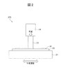
- FIG. 2 shows an outline of a test method using this reciprocating dynamic friction tester.
- the reciprocating friction tester 200 moves relative to the first test tool 22 on the reciprocating table 21, the first test tool 22 placed on the table 21, and the first test tool 22. It has a second test tool 23 that can be arranged, and a load application unit 24 that applies a load to the first test tool 22 via the second test tool 23.
- the first test tool 22 is fixed to the table 21, and the second test tool 23 is fixed to the load applying portion 24.
- the first test tool 22 was made of chrome-plated carbon steel plate, which is the same material as the piston rod
- the second test tool 23 was made of nitrile butadiene rubber, which is the same material as the oil seal.
- a hydraulic oil 30 for a hydraulic system is interposed between the first test tool 22 and the second test tool 23, and the table 21 is reciprocated in this state to bring the first test tool 22 and the second test tool 23 together. The dynamic friction between them was measured.
- the hydraulic oil 30 for the hydraulic system those having various compounding compositions shown in Tables 1 and 2 are sequentially used, and the first test tool 22 and the second test tool when the respective hydraulic oils for the hydraulic system are used.
- the coefficient of dynamic friction with 23 was measured.
- phosphate ester compound (1) is a phosphite ester compound having the structure of diorail hydrogen phosphite in the formula (1)
- phosphate ester compound (2) is , Dilauryl Hydrogenphosphite.
- Test machine name used Bowden tester HEIDON-14D type 1st test tool material: Chrome-plated carbon steel plate 2nd test tool material: Nitrile butadiene rubber [Test conditions] Test temperature: 60 ° C. Applied load of load application part: 20N Table operating amplitude: 10 mm Table speed: 2 mm / sec
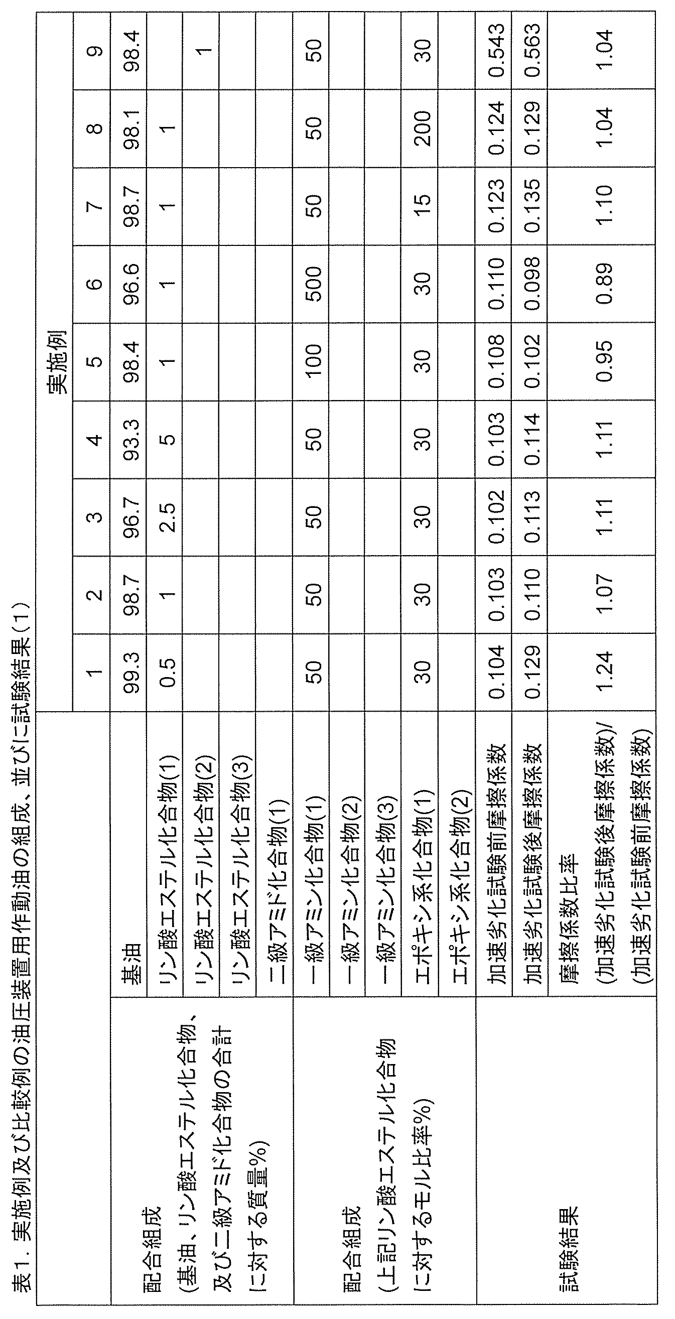
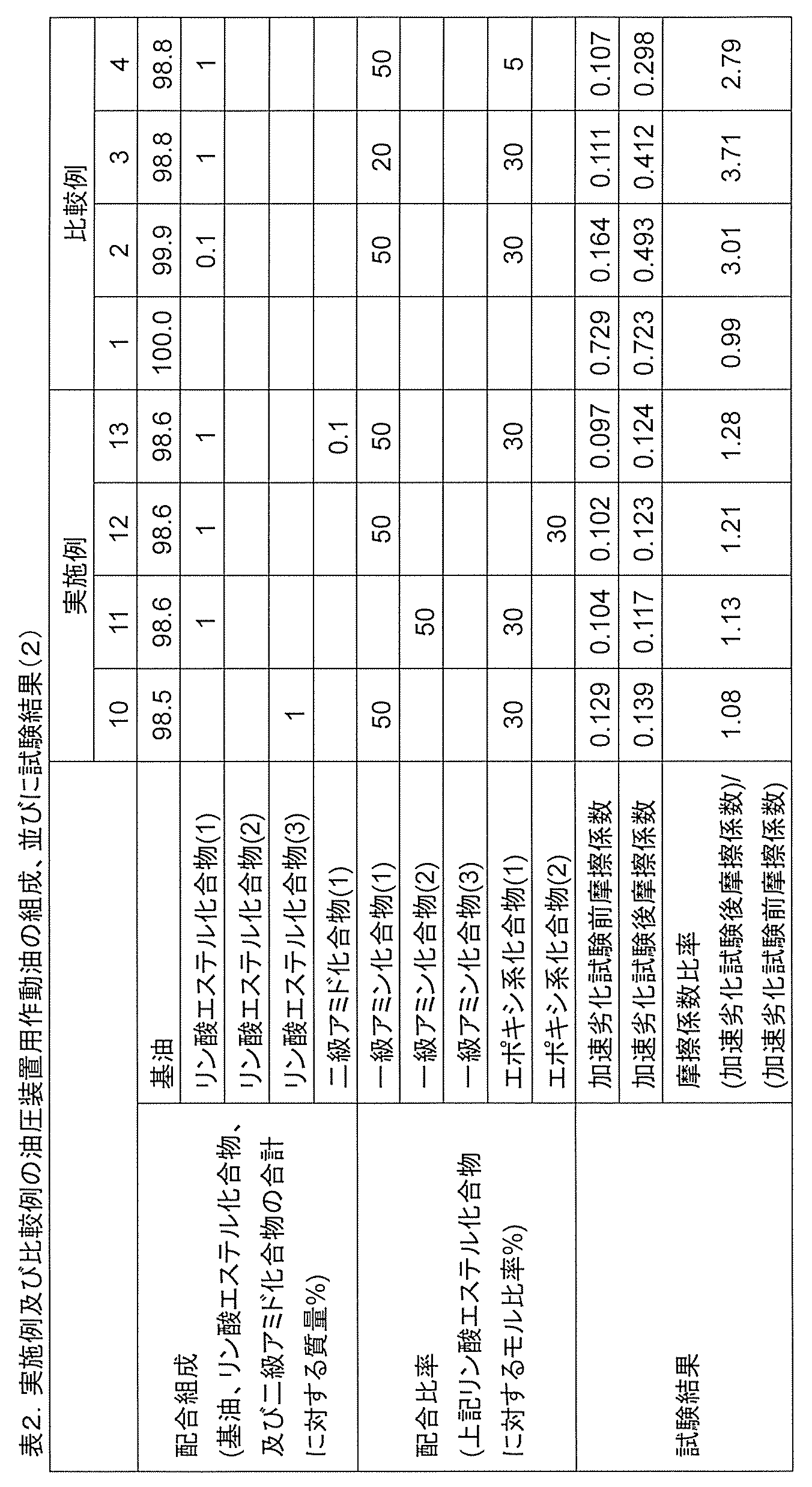
- Tables 1 and 2 show the results of measuring the friction coefficient before and after the accelerated deterioration test at a test temperature of 60 ° C. for hydraulic fluids having various compositions.
- the fluctuation of the coefficient of friction after the accelerated deterioration test measured by the reciprocating dynamic friction test is the same for all hydraulic fluids for hydraulic systems. Compared with the friction coefficient before the accelerated deterioration test, it is within about 0.03. Further, the value obtained by dividing the friction coefficient after the accelerated deterioration test by the friction coefficient before the accelerated deterioration test (friction coefficient ratio) is a value close to 1 (range of 0.89 to 1.28) in all the examples. there were.
- the hydraulic oil for the hydraulic system of Comparative Example 1 has a composition of only the base oil, and does not contain any of the phosphate ester compound, the primary amine compound and the epoxy compound.
- the test results for Comparative Example 1 showed that the friction coefficient before the accelerated deterioration test was 0.729 and the friction coefficient after the accelerated deterioration test was 0.723, and the friction coefficient ratio before and after the accelerated deterioration test was as small as 0.99.
- the coefficient of friction between the piston rod and the oil seal is high. Therefore, when the hydraulic oil for the hydraulic system of Comparative Example 1 was used for the shock absorber for an automobile, the piston rod did not move smoothly, so that a rugged feeling was transmitted to the rider, suggesting that the ride quality was inferior.
- the hydraulic oil for the hydraulic device of Comparative Example 2 contains a phosphite ester compound in the base oil, but the amount is as small as 0.1% by mass with respect to the total of the base oil and the phosphite ester compound. Is. Therefore, the friction coefficient before the accelerated deterioration test was 0.164, while the friction coefficient after the accelerated deterioration test was 0.493, which was significantly increased. Therefore, it was suggested that when the hydraulic oil for the hydraulic system of Comparative Example 2 was used for the shock absorber for automobiles, the riding comfort deteriorated after about 14 years, which is the average usage period of the passenger car.
- a phosphite ester compound and a primary amine compound are blended in the base oil, and an epoxy compound is further blended in a molar ratio of 5% with respect to the phosphite ester compound. ..
- the test results for Comparative Example 4 were that the coefficient of dynamic friction before the accelerated deterioration test was 0.107, the coefficient of dynamic friction after the accelerated deterioration test was 0.298, and the coefficient of friction before and after the accelerated deterioration test was 2.79. , The coefficient of friction increased significantly after the accelerated deterioration test.
- the coefficient of dynamic friction generated between the oil seal and the piston rod is appropriately reduced, and the average of passenger cars is reduced.
- the coefficient of friction can be kept almost constant for about 14 years, which is a typical usage period.
- the automobile equipped with the automobile shock absorber filled with the hydraulic oil for the hydraulic system according to the first embodiment is equipped with the automobile shock absorber filled with the hydraulic oil for the hydraulic device shown in Comparative Example 1. It was found that the ride quality was superior to that of automobiles even after the accelerated deterioration test. It is presumed that this result is because the friction coefficient is kept low even after the accelerated deterioration test in Example 1.
- an automobile equipped with an automobile shock absorber using the hydraulic oil according to the present invention can reduce the degree to which vibration caused by unevenness of the road surface is transmitted to the passenger for a long period of time, and can maintain a good riding comfort.
- the present invention is not limited to the embodiments described above. Specific constituent materials, parts, and the like may be changed without changing the gist of the present invention. Further, if the components of the present invention are included, it is possible to add a known technique or replace it with a known technique.
Landscapes
- Chemical & Material Sciences (AREA)
- Chemical Kinetics & Catalysis (AREA)
- General Chemical & Material Sciences (AREA)
- Oil, Petroleum & Natural Gas (AREA)
- Organic Chemistry (AREA)
- Engineering & Computer Science (AREA)
- General Engineering & Computer Science (AREA)
- Mechanical Engineering (AREA)
- Lubricants (AREA)
- Fluid-Damping Devices (AREA)
Abstract
本発明は、各成分が長期にわたって安定に存在し、長期使用に伴う摩擦係数の変動が小さい自動車用緩衝器等の油圧装置用作動油を提供することを目的とする。 本発明の油圧装置用作動油は、基油と、亜リン酸エステル化合物及びリン酸エステル化合物からなる群から選択される少なくとも一種と、一級アミン化合物と、グリシジル基又はエポキシ基を有する化合物と、を含み、前記亜リン酸エステル化合物及びリン酸エステル化合物からなる群から選択される少なくとも一種の含有量が、前記基油並びに前記亜リン酸エステル化合物及びリン酸エステル化合物からなる群から選択される少なくとも一種の合計に対して0.1質量%超であり、前記亜リン酸エステル化合物及びリン酸エステル化合物からなる群から選択される少なくとも一種に対する前記一級アミン化合物のモル比率が30%以上500%以下であり、前記亜リン酸エステル化合物及びリン酸エステル化合物からなる群から選択される少なくとも一種に対する前記グリシジル基又はエポキシ基を有する化合物のモル比率が10%以上500%以下であることを特徴とする。
Description
本発明は、油圧装置用作動油及びその油圧装置用作動油を用いた油圧装置に関する。
ピストンロッド、オイルシール、及び作動油を備える油圧装置において、オイルシールはピストンロッドに常に接触するように配置され、油圧装置の内部から作動油が外部に流出することを防ぐ役割を担う。
オイルシールはゴム系の材料により構成されるため、金属により構成されるピストンロッド表面に対する接触面は大きな摩擦係数を持つ。そのため、油圧装置でピストンロッドが往復動する際には、オイルシールとピストンロッドとの間に大きな摩擦力が発生する。
オイルシールとピストンロッドとの間に発生する摩擦力が大き過ぎる場合、ピストンロッドが滑らかに動きにくくなる。特に自動車用緩衝器(ショックアブソーバ)においては、旋回や加減速といった車体の運動に伴い、ピストンロッドの往復動方向に対して垂直な方向からオイルシールに対して力がかかるため、大きな摩擦力が生じやすい環境にある。
そのため、オイルシールとピストンロッドとの間の摩擦係数が大きい自動車用緩衝器を適用した自動車では、路面の凹凸に起因する振動が十分に減衰されないまま搭乗者に伝わり、乗り心地が悪くなるという問題がある。
そのため、オイルシールとピストンロッドとの間の摩擦係数が大きい自動車用緩衝器を適用した自動車では、路面の凹凸に起因する振動が十分に減衰されないまま搭乗者に伝わり、乗り心地が悪くなるという問題がある。
乗り心地を改善するために、自動車用緩衝器の作動油に添加物を配合して、オイルシールとピストンロッドとの間の摩擦力を適宜低減させる試みがなされている。
例えば、特許文献1には、基油に、特定の硫黄含有化合物及び特定の極性基含有化合物を配合することにより、摩擦低減効果を発現する潤滑油組成物が開示されている。極性基含有化合物としては、アミノ基、アミド基及び水酸基から選ばれる少なくとも一種の極性基並びに炭素数3~24のアルキル基を有する化合物が開示されている。また、特許文献1には、耐摩耗剤又は極圧剤として、リン酸エステル化合物、亜リン酸エステル化合物を含む物質を添加できることが開示されている。
特許文献1に記載のように、自動車用緩衝機の作動油に配合されたリン酸エステル化合物及び亜リン酸エステル化合物によってオイルシールとピストンロッドとの間の摩擦係数を任意に低減し、乗り心地を調整することができる。前述の摩擦係数は、例えば操舵性を重視する場合はやや高めに、乗り心地を重視する場合には低めに調整される。しかし、リン酸エステル化合物及び亜リン酸エステル化合物は、摩擦係数の調整能力に優れるものの、経年劣化により失活しやすい。一般的に、自動車用緩衝器に含まれる作動油は、自動車製造時から自動車廃棄時まで一度も交換されることなく使用され続ける。自動車の平均車齢は年々伸びており、自動車検査登録情報協会の調査によれば、2017年時点でおよそ14年に達している。したがって、リン酸エステル化合物又は亜リン酸エステル化合物を配合した従来の緩衝機用作動油を自動車用緩衝器に用いた場合、このような長期間の使用による経年劣化でリン酸エステル化合物又は亜リン酸エステル化合物が失活する結果、摩擦係数が使用開始当初と比較して上昇し、乗り心地が悪化する。そのため、特に自動車用緩衝器のような油圧装置では、長期使用に伴うオイルシールとピストンロッドとの間の摩擦係数の変動を小さくすることが望まれている。
上記従来の状況に鑑み、本発明は、各成分が長期にわたって安定に存在し、長期使用に伴う摩擦係数の変動が小さい自動車用緩衝器等の油圧装置用作動油、及びその作動油を用いた油圧装置を提供することを目的とする。
上記課題を解決するため、本発明の油圧装置用作動油は、基油と、亜リン酸エステル化合物及びリン酸エステル化合物からなる群から選択される少なくとも一種と、一級アミン化合物と、グリシジル基又はエポキシ基を有する化合物と、を含み、前記亜リン酸エステル化合物及びリン酸エステル化合物からなる群から選択される少なくとも一種の含有量が、前記基油並びに前記亜リン酸エステル化合物及びリン酸エステル化合物からなる群から選択される少なくとも一種の合計に対して0.1質量%超であり、前記亜リン酸エステル化合物及びリン酸エステル化合物からなる群から選択される少なくとも一種に対する前記一級アミン化合物のモル比率が30%以上500%以下であり、前記亜リン酸エステル化合物及びリン酸エステル化合物からなる群から選択される少なくとも一種に対する前記グリシジル基又はエポキシ基を有する化合物のモル比率が10%以上500%以下であることを特徴とする。
また、本発明は、上記の油圧装置用作動油を備える油圧装置である。
本明細書は本願の優先権の基礎となる日本国特許出願番号2019-080229号の開示内容を包含する。
本明細書は本願の優先権の基礎となる日本国特許出願番号2019-080229号の開示内容を包含する。
本発明により、各成分が長期にわたり安定に存在し、オイルシール及びピストンロッド間で発生する摩擦係数を長期間にわたって維持可能な油圧装置用作動油、及び該油圧装置用作動油を用いた油圧装置を提供することができる。
前記した以外の課題、構成及び効果は、以下の実施形態の説明により明らかにされる。
前記した以外の課題、構成及び効果は、以下の実施形態の説明により明らかにされる。
以下、実施の形態に基づき本発明を詳細に説明する。
本発明の一実施形態に係る油圧装置用作動油は、(A)基油と、(B)亜リン酸エステル化合物及びリン酸エステル化合物からなる群から選択される少なくとも一種と、(C)一級アミン化合物と、(D)グリシジル基又はエポキシ基を有する化合物と、を含み、前記亜リン酸エステル化合物及びリン酸エステル化合物からなる群から選択される少なくとも一種の含有量が、前記基油並びに前記亜リン酸エステル化合物及びリン酸エステル化合物からなる群から選択される少なくとも一種の合計に対して0.1質量%超であり、前記亜リン酸エステル化合物及びリン酸エステル化合物からなる群から選択される少なくとも一種に対する前記一級アミン化合物のモル比率が30%以上500%以下であり、前記亜リン酸エステル化合物及びリン酸エステル化合物からなる群から選択される少なくとも一種に対する前記グリシジル基又はエポキシ基を有する化合物のモル比率が10%以上500%以下である。
本発明の一実施形態に係る油圧装置用作動油は、(A)基油と、(B)亜リン酸エステル化合物及びリン酸エステル化合物からなる群から選択される少なくとも一種と、(C)一級アミン化合物と、(D)グリシジル基又はエポキシ基を有する化合物と、を含み、前記亜リン酸エステル化合物及びリン酸エステル化合物からなる群から選択される少なくとも一種の含有量が、前記基油並びに前記亜リン酸エステル化合物及びリン酸エステル化合物からなる群から選択される少なくとも一種の合計に対して0.1質量%超であり、前記亜リン酸エステル化合物及びリン酸エステル化合物からなる群から選択される少なくとも一種に対する前記一級アミン化合物のモル比率が30%以上500%以下であり、前記亜リン酸エステル化合物及びリン酸エステル化合物からなる群から選択される少なくとも一種に対する前記グリシジル基又はエポキシ基を有する化合物のモル比率が10%以上500%以下である。
上記(A)の基油としては、油圧装置用作動油として従来使用されている鉱油系及び/又は合成油系の基油から任意の材料を選択可能である。鉱油系の基油としては、例えば、パラフィン系鉱油、ナフテン系鉱油等が挙げられる。
合成油系の基油としては、例えば、ポリブテン、ポリプロピレン、ポリαオレフィン、ポリオールエステル、脂肪酸モノエステル、芳香族モノエステル、脂肪酸ジエステル、脂肪族多塩基酸エステル、芳香族多塩基酸エステル、ポリオールポリエステル、リン酸エステル等のエステル、ポリアルキレングリコール、ポリフェニルエーテル、ポリグリコール、アルキルベンゼン、合成ナフテン、イオン液体等が挙げられる。
これらの基油の中で、本実施形態における基油としてはパラフィン系鉱油、ナフテン系鉱油、ポリαオレフィン、ポリフェニルエーテル、アルキルベンゼン、合成ナフテン、シリコーン、ポリアルキレングリコール等が好ましい。これらの基油は、いずれか一種を単独で用いてもよく、二種以上を組み合わせて用いてもよい。
基油の好ましい動粘度は、油圧装置用作動油が適用される油圧装置により異なるが、例えば油圧装置が自動車用緩衝器である場合、低温状態における流動性の観点から、40℃における動粘度(ISO3448:1992に基づく試験)が、8mm2/s(cSt)以上、17mm2/s(cSt)以下の範囲であることが好ましい。
上記(B)の材料としては、亜リン酸エステル化合物及びリン酸エステル化合物からなる群から選択される少なくとも一種を用いる。リン酸エステル化合物及び亜リン酸エステル化合物のいずれも、ピストンロッド表面に露出した金属の触媒作用によりリン酸基及び/又は亜リン酸基がプロトンを放出してピストンロッドの表面に吸着され、安定した吸着膜を形成する。形成された吸着膜の厚さはリン酸エステル化合物及び亜リン酸エステル化合物のアルキル基の長さに依存する。アルキル基の長さを変更することによって吸着膜の厚さを制御し、ピストンロッド及びオイルシール間で発生する摩擦係数を任意に調節することが可能である。
上記(B)の材料として用いる亜リン酸エステル化合物は、下記式(1)に示す構造を有することが好ましい。式(1)において、R1及びR2は、一方が水素又は炭素数3以上30以下の炭化水素基であり、他方が炭素数3以上30以下の炭化水素基である。溶解性の観点から、上記の炭素数は3以上18以下であればより好ましい。これらの炭化水素基は、飽和炭化水素基であるアルキル基であってもよいし、あるいはアルケニル基等の不飽和炭化水素基であってもよい。一方が飽和炭化水素基であり、他方が不飽和炭化水素基であってもよい。

また、上記(B)の材料として用いられるリン酸エステル化合物は、下記式(2)に示す構造を有することが好ましい。式(2)において、R3及びR4は、一方が水素又は炭素数3以上30以下の炭化水素基であり、他方が炭素数3以上30以下の炭化水素基である。上記の炭素数は3以上18以下であればより好ましい。これらの炭化水素基は、飽和炭化水素基であるアルキル基であってもよいし、あるいはアルケニル基等の不飽和炭化水素基であってもよい。一方が飽和炭化水素基であり、他方が不飽和炭化水素基であってもよい。

上記の亜リン酸エステル化合物及びリン酸エステル化合物における飽和炭化水素基の例としては、ジエチルヘキシル基、ラウリル基、ミリスチル基、セチル基、ステアリル基等のアルキル基が挙げられる。また、不飽和炭化水素基の例としては、オレイル基等が挙げられる。R1、R2、R3及びR4は、全て同一の炭化水素基であってもよいし、異なる炭化水素基であってもよい。あるいは、R1、R2、R3及びR4のうち、一部が同一の炭化水素基であり、それ以外は異なる炭化水素基により構成されていてもよい。(B)の材料として用いられる亜リン酸エステル化合物及び/又はリン酸エステル化合物は、いずれか一種を単独で用いてもよいし、複数種の亜リン酸エステル化合物及び/又はリン酸エステル化合物を混合して用いてもよい。
(B)の材料として用いる亜リン酸エステル化合物の具体例としては、ジエチルヘキシルハイドロジェンホスファイト、ジラウリルハイドロジェンホスファイト、ジステアリルハイドロジェンホスファイト、ジオレイルハイドロジェンホスファイト等が挙げられる。
特に、ジオレイルハイドロジェンホスファイトが好ましく用いられる。また、(B)の材料として用いるリン酸エステル化合物としては、エチルヘキシルアシッドホスフェート、ラウリルアシッドホスフェート、ステアリルアシッドホスフェート、オレイルアシッドホスフェート等が挙げられる。
特に、ジオレイルハイドロジェンホスファイトが好ましく用いられる。また、(B)の材料として用いるリン酸エステル化合物としては、エチルヘキシルアシッドホスフェート、ラウリルアシッドホスフェート、ステアリルアシッドホスフェート、オレイルアシッドホスフェート等が挙げられる。
(B)の材料の配合量は、(A)の基油及び(B)の材料の合計に対して0.3質量%以上5.0質量%以下であることがより好ましい。なお、(B)の材料は、0.1質量%を超える配合量であれば効果を発揮し、0.3質量%以上配合されることで十分な効果を発揮する。また、配合量が5.0質量%を超えても同様の効果を発揮するが、基油への溶解性を良好に維持する観点から、配合量は5.0質量%以下であることが好ましい。
(C)の材料である一級アミン化合物としては、アンモニアの水素原子の一つを炭化水素基又は芳香族基によって置換した化合物であれば適用可能である。好ましくは、一級アミン化合物として下記式(3)で表される化合物を用いる。式(3)において、R5は、炭素数12以上30以下の飽和又は不飽和炭化水素基である。ただし、基油への良好な溶解性を確保する観点から、これらの炭化水素基の炭素数は12以上22以下であることがより好ましい。このような飽和炭化水素基の例として、ドデシル基、ミリスチル基、セチル基、ステアリル基等のアルキル基が挙げられる。また、不飽和炭化水素基として、オレイル基、エルシル基等のアルケニル基等が挙げられる。

上記(B)の材料である亜リン酸エステル化合物及びリン酸エステル化合物は、長期使用に伴う劣化により酸性リン酸エステル化合物を生じる。このような酸性リン酸エステル化合物は反応性が高く、上記(B)の亜リン酸エステル化合物及びリン酸エステル化合物を攻撃するため、連鎖的に(B)の材料の劣化が進行する。上記(C)の一級アミン化合物は、酸性リン酸エステル化合物を捕捉することで(B)の材料の連鎖的な劣化反応を防ぎ、オイルシールとピストンロッド間の摩擦係数を長期間にわたって保つことを可能にする。
上記(C)の材料の具体例としては、ドデシルアミン、パルミチルアミン、パルミトレイルアミン、オレイルアミン等が挙げられる。オレイルアミンは特に好ましく用いられる。
(C)の材料である一級アミン化合物の配合量については、(B)の材料に対する一級アミン化合物のモル比率が30%以上500%以下であり、好ましくは50%以上300%以下である。なお、(C)の一級アミン化合物のモル比率が30%以上であれば効果を発揮し、50%以上300%以下の範囲で配合されることで十分な効果を発揮する。モル比率が300%を超えても同様の効果を発揮するが、過剰に配合した一級アミン化合物は十分に基油へ溶解せず、亜リン酸エステル化合物の表面吸着を阻害する悪影響を持つ。そのため、モル比率は300%以下であることがより好ましい。
(D)の材料であるグリシジル基又はエポキシ基を有する化合物としては、任意の化合物を採用することができるが、特に、下記式(4)で表されるグリシジルエーテルが好ましく用いられる。式(4)において、R6は、炭素数3以上30以下の飽和又は不飽和炭化水素基である。ただし、基油への良好な溶解性を確保する観点から、これらの炭化水素基の炭素数は8以上22以下であることがより好ましい。このような炭化水素基の例として、ラウリル基、ミリスチル基、セチル基、ステアリル基等のアルキル基が挙げられる。
また、不飽和炭化水素基として、オレイル基、エルシル基等のアルケニル基が挙げられる。
また、不飽和炭化水素基として、オレイル基、エルシル基等のアルケニル基が挙げられる。
上記(D)の材料の具体例としては、ブチルグリシジルエーテル、オクチルグリシジルエーテル、ステアリルグリシジルエーテル等が挙げられる。特に好ましくは、オクチルグリシジルエーテルである。
上述のように、(C)の材料である一級アミン化合物は、酸性リン酸エステル化合物を捕捉することで(B)の亜リン酸エステル化合物及び/又はリン酸エステル化合物の連鎖的な劣化反応を防ぎ、(B)がオイルシールとピストンロッド間における摩擦の調節機能を長期間にわたって保つことを可能にする。しかし同時に、(C)の一級アミン化合物は、(B)の亜リン酸エステル化合物及び/又はリン酸エステル化合物に対する攻撃性を持つ。したがって、(A)基油に対し、(B)亜リン酸エステル化合物及び/又はリン酸エステル化合物、及び(C)一級アミン化合物のみが配合された油圧装置用作動油では、長期間の使用により(C)一級アミン化合物による攻撃で(B)亜リン酸エステル化合物及び/又はリン酸エステル化合物の効果が失活し、摩擦力が上昇する。ここで、油圧装置用作動油に対し前述の(D)の材料であるグリシジル基又はエポキシ基を有する化合物を配合することで、上記(B)亜リン酸エステル化合物やリン酸エステル化合物の分解反応を抑制することができる。これによって、(B)亜リン酸エステル化合物及び/又はリン酸エステル化合物の劣化により生じる酸性リン酸エステル化合物を(C)の一級アミン化合物で捕捉することで連鎖的な劣化反応を抑制しつつ、(C)一級アミン化合物の攻撃による(B)亜リン酸エステル化合物及び/又はリン酸エステル化合物の分解をも同時に抑制し、オイルシール及びピストンロッド間で発生する摩擦係数を長期間にわたって変動なく保つことができる。
(D)の材料であるグリシジル基又はエポキシ基を有する化合物の配合量については、(B)の材料に対するグリシジル基又はエポキシ基を有する化合物のモル比率が10%以上500%以下であり、好ましくは50%以上300%以下である。なお、(D)のグリシジル基又はエポキシ基を有する化合物のモル比率が10%以上であれば効果を発揮し、50%以上配合されることで十分な効果を発揮する。また、モル比率が300%を超えても同様の効果を発揮するが、基油への溶解性を良好に維持する観点から、モル比率は300%以下であることが好ましい。
また、本実施形態に係る油圧装置用作動油は、必要に応じて、下記式(5)で表される二級アミド化合物をさらに配合することができる。式(5)において、R7及びR8は、それぞれ独立して炭素数8以上24以下の飽和又は不飽和炭化水素基である。ただし、基油への良好な溶解性を確保する観点から、これらの炭化水素基の炭素数は12以上22以下であることがより好ましい。このような飽和炭化水素基の例として、ドデシル基、ミリスチル基、セチル基、ステアリル基等のアルキル基が挙げられる。また、不飽和炭化水素基として、オレイル基、エルシル基等のアルケニル基等が挙げられる。
上記二級アミド化合物の具体例としては、N-ステアリルオレイン酸アミド、N-ステアリルエルシリン酸アミド、N-セチルオレイン酸アミド、N-セチルエルシリン酸アミド、N-ミリスチルオレイン酸アミド、N-ミリスチルエルシリン酸アミド、N-ドデシルオレイン酸アミド、N-ドデシルエルシリン酸アミド等が挙げられる。
二級アミド化合物の配合量については、(A)の基油、(B)の亜リン酸エステル化合物及びリン酸エステルからなる群から選択される少なくとも一種、及び二級アミド化合物の合計に対して、0.01質量%以上2.0質量%以下の範囲とすることが好ましい。
本実施形態に係る油圧装置用作動油には、その効果を阻害しない範囲で添加剤を適宜配合してもよい。具体的な添加剤としては、摩耗防止剤、油性向上剤、酸化防止剤、無灰系分散剤、金属系分散剤、粘度指数向上剤、流動点降下剤、金属不活性化剤、防錆剤、及び消泡剤等が挙げられる。
これらの中で、本実施形態に係る油圧装置用作動油は、酸化防止剤、無灰系分散剤、金属系分散剤、粘度指数向上剤、防錆剤、及び消泡剤からなる群から選択される少なくとも一種の添加剤を含むことが好ましい。
摩耗防止剤としては、例えば、ジチオリン酸亜鉛及びその誘導体、硫黄化合物及びその誘導体、二硫化モリブデン及びその誘導体等が挙げられる。
油性向上剤としては、例えば、脂肪族アルコール及びその誘導体、脂肪酸エステル及びその誘導体、脂肪酸及びその誘導体、アミン化合物及びその誘導体等が挙げられる。
酸化防止剤としては、例えば、アミン系酸化防止剤及びその誘導体、フェノール系酸化防止剤及びその誘導体、硫黄系酸化防止剤及びその誘導体、カーバメイト系酸化防止剤及びその誘導体等が挙げられる。
無灰系分散剤としては、例えば、こはく酸イミド及びその誘導体、ベンジルアミン及びその誘導体、エステル及びその誘導体等が挙げられる。
金属系分散剤としては、カルシウムサリシレート及びその誘導体、カルシウムフェネート及びその誘導体、カルシウムスルホネート及びその誘導体、ホウ酸カリウム及びその誘導体等が挙げられる。
粘度指数向上剤としては、ポリメタクリレート及びその誘導体、ポリイソブチレン及びその誘導体、オレフィンコポリマー及びその誘導体等が挙げられる。
流動点降下剤としては、例えば、ポリメタクリレート及びその誘導体、ポリブテン及びその誘導体、ポリアルキルスチレン及びその誘導体等が挙げられる。
金属不活性化剤としては、ベンゾトリアゾール及びその誘導体、チアジアゾール及びその誘導体等が挙げられる。
防錆剤としては、イミダゾール及びその誘導体、ベンゾトリアゾール及びその誘導体、チアジアゾール及びその誘導体等が挙げられる。
消泡剤としては、例えば、シリコーン系消泡剤及びその誘導体、ポリアクリレート系消泡剤及びその誘導体等が挙げられる。
これら各種添加剤の配合量は、合計して、油圧装置用作動油全体の30質量%未満とすることが好ましい。
次に、本実施形態に係る油圧装置用作動油を用いた油圧装置の構成について、図面を参照して説明する。ここでは油圧装置として、複筒式の自動車用緩衝器を例に挙げて説明する。
図1は、本発明の一実施形態に係る自動車用緩衝器100の断面図である。自動車用緩衝器100は複筒式であって、底部を有する筒状の外筒11、及び外筒11の内部に外筒11と同軸に設けられた内筒12から構成されるシリンダ1と、シリンダ1に対して相対的に移動可能なピストンロッド2とを備える。内筒12の内部及び内筒12と外筒11との間のスペースには、油圧装置用作動油3が注入されている。
ピストンロッド2について、内筒12に挿入されたその一端側にはピストン4が固定され、他端はシリンダ1から突出するように配置される。ピストン4の外周部は内筒12の内面に接触する。内筒12の下端にはボトムバルブ5が固定され、内筒12の上端にはブッシュ6が固定される。ブッシュ6の中央には貫通穴が設けられ、この貫通穴にピストンロッド2が挿入される。外筒11の上部にはオイルシール7が固定され、オイルシール7を介して外筒11の内部は密封される。ピストンロッド2はオイルシール7と摺動可能とされ、これにより、オイルシール7は、ピストンロッド2とブッシュ6との隙間を通って油圧装置用作動油3がシリンダ1の外部に漏れるのを防ぐ。なお、ピストンロッド2の表面の少なくとも一部には、必要に応じて、クロムめっきを施すことができる。クロムめっきを備えることにより、摩耗を防止してシール性能の安定性を高めることができる。
図1に示すとおり、自動車用緩衝器100においては、ピストン4は、内筒12の内部を油室Aと油室Bとに隔てている。また、ボトムバルブ5は、内筒12と外筒11との間のスペースと油室Aとを隔てている。ピストン4にはバルブを備えた減衰力発生機構8が設けられている。減衰力発生機構8は、ピストンロッド2が伸長側に移動(ピストンロッド2が図1において上方に移動)する際に、バルブが開いて油室Aと油室Bとの間に断面積の小さな流路を形成し、油圧装置用作動油3の流動を制限することで、所定の減衰力を発生させる。ボトムバルブ5には減衰力発生機構9が設けられている。減衰力発生機構9は、ボトムバルブ5に形成された小断面積の流路により構成される。ピストンロッド2の縮小側に移動(ピストンロッド2が図1において下方に移動)する際に、油室A内の油圧装置用作動油3が小断面積の流路を通ってリザーバ室Cに流動することで減衰力が発生する。
次に、実施例及び比較例により本発明をさらに詳細に説明するが、本発明はこれらの実施例によって限定されるものではない。
(1)加速劣化試験 経年使用に伴う油圧装置用作動油の劣化を再現するために、加速劣化試験を実施した。
後述の実施例又は比較例に示す種々の配合組成の油圧装置用作動油を圧力容器中に密閉し、120℃に維持した恒温槽で120時間の加速劣化試験を実施した。一般的に、外気温が10℃上昇すると、材料の劣化は2倍の速度で進行することが知られている。したがって、120℃における120時間の加速劣化試験により、20℃における約14年の劣化状態を再現できる。加速劣化試験後の油圧装置用作動油を後述する往復動摩擦試験に供し、劣化試験前後の摩擦係数を比較した。
後述の実施例又は比較例に示す種々の配合組成の油圧装置用作動油を圧力容器中に密閉し、120℃に維持した恒温槽で120時間の加速劣化試験を実施した。一般的に、外気温が10℃上昇すると、材料の劣化は2倍の速度で進行することが知られている。したがって、120℃における120時間の加速劣化試験により、20℃における約14年の劣化状態を再現できる。加速劣化試験後の油圧装置用作動油を後述する往復動摩擦試験に供し、劣化試験前後の摩擦係数を比較した。
(2)往復動摩擦試験 油圧装置において、オイルシールとピストンロッドとの間に発生する摩擦力を推定するために、往復動摩擦試験機を用いて種々の配合組成の油圧装置用作動油について試験を行った。往復動摩擦試験機としては新東科学株式会社のバウデン試験機HEIDON-14D型を使用した。図2に、この往復動摩擦試験機を用いた試験方法の概略を示す。往復動摩擦試験機200は、往復運動するテーブル21と、テーブル21の上に載置された第1試験工具22と、第1試験工具22の上で第1試験工具22に対して相対的に移動可能に配置された第2試験工具23と、第2試験工具23を介して第1試験工具22に荷重を印加する荷重印加部24とを有する。テーブル21には第1試験工具22が固定され、荷重印加部24には第2試験工具23が固定される。
第1試験工具22はピストンロッドと同じ材料であるクロムめっき炭素鋼板を材料として作製し、第2試験工具23はオイルシールと同じ材料であるニトリルブタジエンゴムを材料として作製した。第1試験工具22と第2試験工具23との間には油圧装置用作動油30を介在させ、この状態でテーブル21を往復運動させて、第1試験工具22と第2試験工具23との間の動摩擦を測定した。油圧装置用作動油30としては、表1及び表2に示す種々の配合組成のものを順次用いて、各々の油圧装置用作動油を用いた場合における、第1試験工具22と第2試験工具23との間の動摩擦係数を測定した。なお、表1及び表2においては、亜リン酸エステル化合物及びリン酸エステル化合物からなる群から選択される少なくとも一種を「リン酸エステル化合物」と表記し、グリシジル基又はエポキシ基を有する化合物を「エポキシ系化合物」と表記している。表1及び表2中、「リン酸エステル化合物(1)」は式(1)においてジオレイルハイドロジェンホスファイトの構造を有する亜リン酸エステル化合物であり、「リン酸エステル化合物(2)」は、ジラウリルハイドロジェンホスファイトである。上記の試験結果を、ピストンロッドとオイルシールとの間の摩擦力に相当するものとして、上記の種々の配合組成の油圧装置用作動油を評価した。
往復動摩擦試験の条件は下記の通りである。
使用試験機名:バウデン試験機 HEIDON-14D型
第1試験工具の材料:クロムめっき炭素鋼板
第2試験工具の材料:ニトリルブタジエンゴム
〔試験条件〕 試験温度:60℃ 荷重印加部の印加荷重:20N テーブルの動作振幅:10mm テーブルの速度:2mm/sec
使用試験機名:バウデン試験機 HEIDON-14D型
第1試験工具の材料:クロムめっき炭素鋼板
第2試験工具の材料:ニトリルブタジエンゴム
〔試験条件〕 試験温度:60℃ 荷重印加部の印加荷重:20N テーブルの動作振幅:10mm テーブルの速度:2mm/sec
表1及び表2に、種々の組成の油圧装置用作動油に関して、加速劣化試験前後の摩擦係数を試験温度60℃で測定した結果を示す。表1及び表2に示した実施例1~13についての試験結果から明らかなように、いずれの油圧装置用作動油についても、往復動摩擦試験により測定した加速劣化試験後の摩擦係数の変動は、加速劣化試験前の摩擦係数と比較して0.03程度に収まっている。また、加速劣化試験後の摩擦係数を加速劣化試験前の摩擦係数で除した値(摩擦係数比率)は、いずれの実施例についても1に近い値(0.89から1.28の範囲)であった。すなわち、加速劣化試験による摩擦係数の変動は極めて小さい。これらの結果から、実施例1~13の油圧装置用作動油を用いた自動車用緩衝器は、乗用車の平均的な使用期間であるおよそ14年間にわたってピストンロッドとオイルシールとの間の摩擦係数をほぼ一定に維持可能であることが示唆された。
これに対し、比較例1の油圧装置用作動油は、基油のみの組成であり、リン酸エステル化合物、一級アミン化合物及びエポキシ系化合物はいずれも配合されていない。比較例1についての試験結果は、加速劣化試験前の摩擦係数が0.729、加速劣化試験後の摩擦係数が0.723であり、加速劣化試験前後の摩擦係数比率こそ0.99と小さかったが、一方でピストンロッドとオイルシールとの間の摩擦係数は高い。したがって、比較例1の油圧装置用作動油を自動車用緩衝器に使用した場合、ピストンロッドがスムーズに動かないためゴツゴツとした感触が乗り手に伝わり、乗り心地に劣ることが示唆された。
比較例2の油圧装置用作動油は、基油に、亜リン酸エステル化合物は配合されているものの、配合量が基油及び亜リン酸エステル化合物の合計に対して0.1質量%と少量である。そのため、加速劣化試験前の摩擦係数が0.164であるのに対し、加速劣化試験後の摩擦係数は0.493と大きく上昇した。したがって、比較例2の油圧装置用作動油を自動車用緩衝器に使用した場合には、乗用車の平均的な使用期間であるおよそ14年間の使用後は乗り心地が悪化することが示唆された。
比較例3の油圧装置用作動油は、基油に、亜リン酸エステル化合物及びエポキシ系化合物を配合しているが、一級アミン化合物の配合量(モル比率)が亜リン酸エステル化合物に対して20%と少量である。比較例3についての試験結果は、加速劣化試験前の摩擦係数が0.111、加速劣化試験後の摩擦係数が0.412であり、また、加速劣化試験前後の摩擦係数比率は3.71となり、加速劣化試験後に摩擦係数が大きく上昇した。これは、一級アミン化合物の配合量が不十分であるため、亜リン酸エステル化合物の分解生成物により連鎖的に劣化が進行したからである。したがって、比較例3の油圧装置用作動油を自動車用緩衝器に使用した場合には、乗用車の平均的な使用期間であるおよそ14年間の使用後は乗り心地が悪化することが示唆された。
比較例4の油圧装置用作動油は、基油に、亜リン酸エステル化合物、及び一級アミン化合物を配合し、さらに、エポキシ系化合物を亜リン酸エステル化合物に対するモル比率で5%配合している。比較例4についての試験結果は、加速劣化試験前の動摩擦係数が0.107、加速劣化試験後の動摩擦係数が0.298であり、また、加速劣化試験前後の摩擦係数比率は2.79となり、加速劣化試験後に摩擦係数が大きく上昇した。これは、エポキシ系化合物の配合量が不十分であるために、一級アミン化合物による亜リン酸エステルの分解反応を十分抑制することができなかったからである。したがって、比較例4の油圧装置用作動油を自動車用緩衝器に使用した場合には、乗用車の平均的な使用期間であるおよそ14年間の使用後は乗り心地が悪化することが示唆された。
以上説明したように、本発明の実施例に係る油圧装置用作動油を油圧装置に用いた場合には、オイルシールとピストンロッドとの間で発生する動摩擦係数を適宜低減するとともに、乗用車の平均的な使用期間であるおよそ14年間にわたって摩擦係数をほぼ一定に保つことができる。
(2)自動車用緩衝器を搭載した自動車による官能試験 実施例1及び比較例1に係る2種類の配合組成の油圧装置用作動油に対して、120℃で120時間の加速劣化試験を実施し、試験前後の作動油を封入した自動車用緩衝器を作製した。この自動車用緩衝器を実際に搭載した自動車を動かし、その乗り心地についての官能試験を行った。具体的には、官能試験を行う2名の試験者が、加速劣化試験実施前後の油圧装置用作動油を封入した自動車用緩衝器を搭載する自動車に搭乗し、路面の凹凸に起因する振動が伝わる度合いについて5点満点で評価した。評価点は高いほど(数値が大きいほど)乗り心地が優れていることを示す。2名の試験者による評価点の平均点を最終的な評価点とした。その結果を表3に示す。
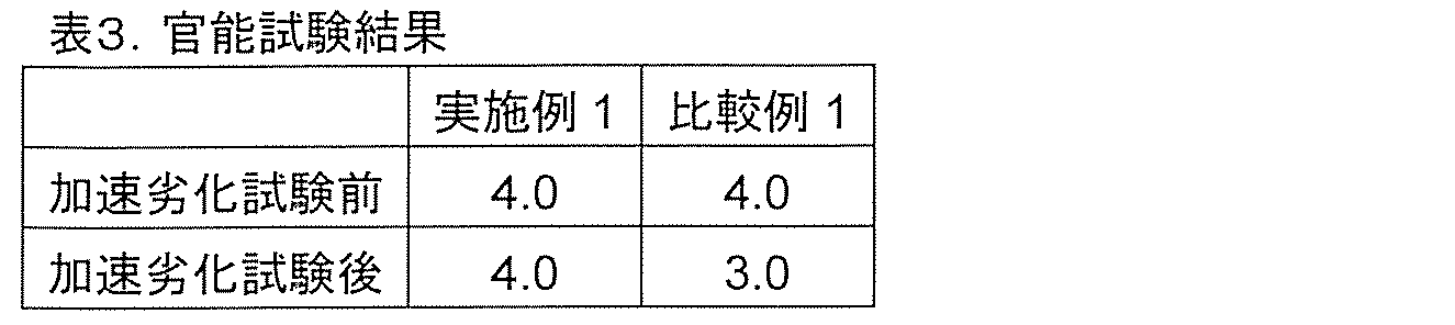
表3に示すように、実施例1の油圧装置用作動油を封入した自動車用緩衝器を搭載した自動車は、比較例1に示した油圧装置用作動油を封入した自動車用緩衝器を搭載した自動車に比べて、加速劣化試験後も乗り心地が優れていることが分かった。この結果は、実施例1では加速劣化試験後も摩擦係数が低く保たれているためと推測される。
なお、実施例1以外の実施例の油圧装置用作動油を用いた自動車用緩衝器を搭載した自動車においても、実施例1の油圧装置用作動油を用いた場合と同様に、加速劣化試験前後の乗り心地の変動が小さいという結果が得られる。また、比較例1以外の比較例の油圧装置用作動油を用いた自動車用緩衝器を搭載した自動車においても、比較例1の油圧装置用作動油を用いた場合と同様に、加速劣化試験前後で乗り心地の変動が大きいという結果が得られる。
以上説明したとおり、本発明により、オイルシールとピストンロッドとの摩擦係数を長期間にわたって低減し、且つ摩擦係数の変動が小さい油圧装置用作動油を提供することができる。さらに、その油圧装置用作動油を用いた油圧装置を提供することができる。本発明に係る作動油を用いた自動車用緩衝器を搭載した自動車は、路面の凹凸に起因する振動が搭乗者に伝わる度合いを長期にわたって低減し、よい乗り心地を維持することができる。
なお、本発明は、以上説明した実施の形態に限定されない。本発明の要旨を変更しない範囲で、具体的な構成材料、部品等を変更してもよい。また、本発明の構成要素を含んでいれば、公知の技術を追加し、あるいは公知の技術で置き換えることも可能である。
1…シリンダ、2…ピストンロッド、3…油圧装置用作動油、4…ピストン、5…ボトムバルブ、6…ブッシュ、7…オイルシール、8、9…減衰力発生機構、11…外筒、12…内筒、21…テーブル、22…第1試験工具、23…第2試験工具、24…荷重印加部、30…油圧装置用作動油、100…自動車用緩衝器、200…往復動摩擦試験機
本明細書で引用した全ての刊行物、特許及び特許出願はそのまま引用により本明細書に組み入れられるものとする。
本明細書で引用した全ての刊行物、特許及び特許出願はそのまま引用により本明細書に組み入れられるものとする。
Claims (14)
- 基油と、
亜リン酸エステル化合物及びリン酸エステル化合物からなる群から選択される少なくとも一種と、
一級アミン化合物と、
グリシジル基又はエポキシ基を有する化合物と、を含み、
前記亜リン酸エステル化合物及びリン酸エステル化合物からなる群から選択される少なくとも一種の含有量が、前記基油並びに前記亜リン酸エステル化合物及びリン酸エステル化合物からなる群から選択される少なくとも一種の合計に対して0.1質量%超であり、
前記亜リン酸エステル化合物及びリン酸エステル化合物からなる群から選択される少なくとも一種に対する前記一級アミン化合物のモル比率が30%以上500%以下であり、
前記亜リン酸エステル化合物及びリン酸エステル化合物からなる群から選択される少なくとも一種に対する前記グリシジル基又はエポキシ基を有する化合物のモル比率が10%以上500%以下である、油圧装置用作動油。 - 前記亜リン酸エステル化合物が、式(1)

前記リン酸エステル化合物が、式(2)
- 前記一級アミン化合物が、式(3)

- 前記グリシジル基又はエポキシ基を有する化合物が、式(4)

- 前記亜リン酸エステル化合物及びリン酸エステル化合物からなる群から選択される少なくとも一種の含有量が、前記基油並びに前記亜リン酸エステル化合物及びリン酸エステル化合物からなる群から選択される少なくとも一種の合計に対して0.3質量%以上5.0質量%以下である、請求項1に記載の油圧装置用作動油。
- 式(5)
- 前記二級アミド化合物の含有量が、前記基油、並びに前記亜リン酸エステル化合物及びリン酸エステル化合物からなる群から選択される少なくとも一種、並びに前記二級アミド化合物の合計に対して0.01質量%以上2.0質量%以下である、請求項6に記載の油圧装置用作動油。
- 前記亜リン酸エステル化合物及びリン酸エステル化合物からなる群から選択される少なくとも一種が、ジオレイルハイドロジェンホスファイトである、請求項1に記載の油圧装置用作動油。
- 前記一級アミン化合物が、オレイルアミンである、請求項1に記載の油圧装置用作動油。
- 前記グリシジル基又はエポキシ基を有する化合物が、オクチルグリシジルエーテルである、請求項1に記載の油圧装置用作動油。
- 請求項1に記載の油圧装置用作動油を備える油圧装置。
- シリンダと、
前記シリンダに対して相対的に移動可能なピストンロッドと、
前記シリンダに固定され前記ピストンロッドと摺動するオイルシールと、
前記シリンダの内部に注入された請求項1に記載の油圧装置用作動油と、を備える、請求項11に記載の油圧装置。 - 前記ピストンロッドの表面の少なくとも一部にクロムめっきが施されている、請求項12に記載の油圧装置。
- 自動車用緩衝器である、請求項12に記載の油圧装置。
Applications Claiming Priority (2)
| Application Number | Priority Date | Filing Date | Title |
|---|---|---|---|
| JP2019080229A JP7261074B2 (ja) | 2019-04-19 | 2019-04-19 | 油圧装置用作動油及びその油圧装置用作動油を用いた油圧装置 |
| JP2019-080229 | 2019-04-19 |
Publications (1)
| Publication Number | Publication Date |
|---|---|
| WO2020213504A1 true WO2020213504A1 (ja) | 2020-10-22 |
Family
ID=72837855
Family Applications (1)
| Application Number | Title | Priority Date | Filing Date |
|---|---|---|---|
| PCT/JP2020/015893 Ceased WO2020213504A1 (ja) | 2019-04-19 | 2020-04-08 | 油圧装置用作動油及びその油圧装置用作動油を用いた油圧装置 |
Country Status (2)
| Country | Link |
|---|---|
| JP (1) | JP7261074B2 (ja) |
| WO (1) | WO2020213504A1 (ja) |
Cited By (1)
| Publication number | Priority date | Publication date | Assignee | Title |
|---|---|---|---|---|
| WO2026018551A1 (ja) * | 2024-07-19 | 2026-01-22 | Astemo株式会社 | 油圧機器および油圧機器用作動流体 |
Families Citing this family (1)
| Publication number | Priority date | Publication date | Assignee | Title |
|---|---|---|---|---|
| JP7618611B2 (ja) * | 2022-03-08 | 2025-01-21 | 株式会社東芝 | 原子炉格納容器内オイルダンパ、および、制振システム |
Citations (4)
| Publication number | Priority date | Publication date | Assignee | Title |
|---|---|---|---|---|
| JP2011162766A (ja) * | 2010-01-18 | 2011-08-25 | Jx Nippon Oil & Energy Corp | 潤滑油組成物 |
| JP2013108033A (ja) * | 2011-11-24 | 2013-06-06 | Mitsubishi Heavy Ind Ltd | 潤滑油組成物 |
| JP2013155349A (ja) * | 2012-01-31 | 2013-08-15 | Idemitsu Kosan Co Ltd | 緩衝器油組成物 |
| JP2018002844A (ja) * | 2016-06-30 | 2018-01-11 | 日立オートモティブシステムズ株式会社 | 油圧装置用作動油およびその油圧装置用作動油を用いた油圧装置 |
-
2019
- 2019-04-19 JP JP2019080229A patent/JP7261074B2/ja active Active
-
2020
- 2020-04-08 WO PCT/JP2020/015893 patent/WO2020213504A1/ja not_active Ceased
Patent Citations (4)
| Publication number | Priority date | Publication date | Assignee | Title |
|---|---|---|---|---|
| JP2011162766A (ja) * | 2010-01-18 | 2011-08-25 | Jx Nippon Oil & Energy Corp | 潤滑油組成物 |
| JP2013108033A (ja) * | 2011-11-24 | 2013-06-06 | Mitsubishi Heavy Ind Ltd | 潤滑油組成物 |
| JP2013155349A (ja) * | 2012-01-31 | 2013-08-15 | Idemitsu Kosan Co Ltd | 緩衝器油組成物 |
| JP2018002844A (ja) * | 2016-06-30 | 2018-01-11 | 日立オートモティブシステムズ株式会社 | 油圧装置用作動油およびその油圧装置用作動油を用いた油圧装置 |
Cited By (1)
| Publication number | Priority date | Publication date | Assignee | Title |
|---|---|---|---|---|
| WO2026018551A1 (ja) * | 2024-07-19 | 2026-01-22 | Astemo株式会社 | 油圧機器および油圧機器用作動流体 |
Also Published As
| Publication number | Publication date |
|---|---|
| JP2020176224A (ja) | 2020-10-29 |
| JP7261074B2 (ja) | 2023-04-19 |
Similar Documents
| Publication | Publication Date | Title |
|---|---|---|
| CN101517055B (zh) | 缓冲器用润滑油组合物 | |
| JP6353840B2 (ja) | 緩衝器用潤滑油組成物 | |
| JP5965231B2 (ja) | 緩衝器用潤滑油組成物 | |
| JP5879168B2 (ja) | 緩衝器用潤滑油組成物 | |
| JP6723097B2 (ja) | 油圧装置用作動油およびその油圧装置用作動油を用いた油圧装置 | |
| CN105492584B (zh) | 缓冲器用润滑油组合物 | |
| US9458405B2 (en) | Lubricating oil composition | |
| JP7261074B2 (ja) | 油圧装置用作動油及びその油圧装置用作動油を用いた油圧装置 | |
| US9745534B2 (en) | Shock absorber oil composition | |
| WO2009150900A1 (ja) | 潤滑油組成物 | |
| EP3473695A1 (en) | Hydraulic fluid | |
| KR20140117431A (ko) | 완충기유 조성물 | |
| KR20160047471A (ko) | 완충기용 윤활유 조성물 | |
| JP5087262B2 (ja) | 自動車緩衝器用潤滑油組成物 | |
| JP5483301B2 (ja) | 緩衝器用油圧作動油組成物 | |
| JP6949677B2 (ja) | 緩衝器用潤滑油組成物 | |
| JPH09176672A (ja) | 緩衝器用油圧作動油組成物 | |
| WO2022009791A1 (ja) | 潤滑油組成物、緩衝器、及び潤滑油組成物の使用方法 | |
| WO2020218522A1 (ja) | 潤滑油組成物 | |
| JP4681285B2 (ja) | 緩衝器用油圧作動油組成物 | |
| JP2006335966A (ja) | 緩衝器用油圧作動油組成物 | |
| JP4681286B2 (ja) | 緩衝器用油圧作動油組成物 | |
| WO2006129889A1 (ja) | 緩衝器用油圧作動油組成物 |
Legal Events
| Date | Code | Title | Description |
|---|---|---|---|
| 121 | Ep: the epo has been informed by wipo that ep was designated in this application |
Ref document number: 20791108 Country of ref document: EP Kind code of ref document: A1 |
|
| NENP | Non-entry into the national phase |
Ref country code: DE |
|
| 122 | Ep: pct application non-entry in european phase |
Ref document number: 20791108 Country of ref document: EP Kind code of ref document: A1 |