WO2020204201A1 - 飛行体 - Google Patents
飛行体 Download PDFInfo
- Publication number
- WO2020204201A1 WO2020204201A1 PCT/JP2020/015437 JP2020015437W WO2020204201A1 WO 2020204201 A1 WO2020204201 A1 WO 2020204201A1 JP 2020015437 W JP2020015437 W JP 2020015437W WO 2020204201 A1 WO2020204201 A1 WO 2020204201A1
- Authority
- WO
- WIPO (PCT)
- Prior art keywords
- inspection
- flying object
- flight
- flight controller
- recognition unit
- Prior art date
- Legal status (The legal status is an assumption and is not a legal conclusion. Google has not performed a legal analysis and makes no representation as to the accuracy of the status listed.)
- Ceased
Links
Images

Classifications
-
- B—PERFORMING OPERATIONS; TRANSPORTING
- B64—AIRCRAFT; AVIATION; COSMONAUTICS
- B64C—AEROPLANES; HELICOPTERS
- B64C13/00—Control systems or transmitting systems for actuating flying-control surfaces, lift-increasing flaps, air brakes, or spoilers
- B64C13/02—Initiating means
- B64C13/16—Initiating means actuated automatically, e.g. responsive to gust detectors
- B64C13/18—Initiating means actuated automatically, e.g. responsive to gust detectors using automatic pilot
-
- B—PERFORMING OPERATIONS; TRANSPORTING
- B64—AIRCRAFT; AVIATION; COSMONAUTICS
- B64D—EQUIPMENT FOR FITTING IN OR TO AIRCRAFT; FLIGHT SUITS; PARACHUTES; ARRANGEMENT OR MOUNTING OF POWER PLANTS OR PROPULSION TRANSMISSIONS IN AIRCRAFT
- B64D47/00—Equipment not otherwise provided for
- B64D47/08—Arrangements of cameras
-
- G—PHYSICS
- G05—CONTROLLING; REGULATING
- G05D—SYSTEMS FOR CONTROLLING OR REGULATING NON-ELECTRIC VARIABLES
- G05D1/00—Control of position, course, altitude or attitude of land, water, air or space vehicles, e.g. using automatic pilots
- G05D1/10—Simultaneous control of position or course in three dimensions
-
- B—PERFORMING OPERATIONS; TRANSPORTING
- B64—AIRCRAFT; AVIATION; COSMONAUTICS
- B64U—UNMANNED AERIAL VEHICLES [UAV]; EQUIPMENT THEREFOR
- B64U2101/00—UAVs specially adapted for particular uses or applications
- B64U2101/30—UAVs specially adapted for particular uses or applications for imaging, photography or videography
-
- B—PERFORMING OPERATIONS; TRANSPORTING
- B64—AIRCRAFT; AVIATION; COSMONAUTICS
- B64U—UNMANNED AERIAL VEHICLES [UAV]; EQUIPMENT THEREFOR
- B64U2201/00—UAVs characterised by their flight controls
- B64U2201/20—Remote controls
Definitions
- the present invention relates to an air vehicle.
- Patent Document 1 discloses a technique for acquiring distance measurement data based on a measured value obtained based on the reflected light of a laser beam emitted from an air vehicle and information on an irradiation direction of the laser beam.
- an inspection image for example, a still image or a moving image
- an inspection object for example, a structure
- the flying object flies straight (horizontally) with respect to the inspection object and keeps a certain distance. It is required to fly stably at a constant speed while maintaining it.
- flying an air vehicle near an object to be inspected it is difficult for even a skilled pilot to fly the air vehicle stably due to the influence of wind and the like.
- the present invention has been made in view of such a background, and an object of the present invention is to capture a stable inspection image by an air vehicle.
- the main invention of the present invention for solving the above problems is a recognition unit that recognizes a laser beam emitted from a laser irradiation device to an inspection object, a flight controller that controls flight according to the recognized laser beam, and the like. Will be provided.
- a stable inspection image can be captured by the flying object.
- the flying object according to the embodiment of the present invention has the following configuration.
- a recognition unit that recognizes the laser light emitted from the laser irradiation device to the inspection target, A flight controller that controls flight according to the recognized laser beam, Aircraft equipped with.
- the flying object according to item 1 The recognition unit recognizes the inspection route by the laser beam that the laser irradiation device irradiates the inspection object. The flight controller controls the flight so as to follow the recognized inspection route. An air vehicle characterized by that.
- [Item 3] The flying object according to item 2.
- An imaging unit that captures inspection images of the inspection object, Aircraft equipped with.
- the photographing unit stops photographing the inspection image when the recognition unit does not recognize the inspection route.
- [Item 5] The flying object according to item 4.
- the flight controller stops accepting instructions from the pilot to move the aircraft along the inspection route when the recognition unit does not recognize the inspection route. An air vehicle characterized by that.
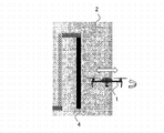
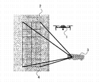
- FIG. 1 is a diagram illustrating a flight state of the flying object 1 according to the present embodiment.
- the flying object 1 captures an inspection video (for example, a moving image) of a structure 2 which is an inspection target such as a pillar, a wall, or a ceiling.
- a laser irradiation device 3 is arranged around the structure 2 and irradiates the laser beam 4 toward a portion of the structure 2 to be inspected.
- the inspection image of the structure 2 can be stably photographed.
- the laser irradiation device 3 projects an inspection route onto the structure 2 by the laser light 4 to irradiate.
- the inspection route can be fixed to the structure 2 for irradiation.
- This inspection route includes one or more straight lines, curves, and combinations thereof.
- the laser irradiation device 3 may change the color and the number of pulses of each of the lines constituting the inspection route.
- the laser irradiation device 3 may distinguish between the color of the laser beam 4 projected in the vertical direction and the color of the laser beam 4 projected in the horizontal direction. Further, the laser irradiation device 3 may distinguish each color of the laser beam 4 projected in the vertical direction, for example.
- the flying object 1 can accurately grasp the inspection route even when the laser beam 4 irradiated to the structure 2 cannot be recognized.
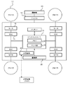
- FIG. 2 is a functional block diagram of the flying object 1 according to the present embodiment.
- the flight controller 11 can have one or more processors such as a programmable processor (for example, a central processing unit (CPU)).
- a programmable processor for example, a central processing unit (CPU)
- CPU central processing unit
- the flight controller 11 has a memory 12 and can access the memory 12.
- the memory 12 stores logic, code, and / or program instructions that the flight controller 11 can execute to perform one or more steps.
- the memory 12 may include, for example, a separable medium such as an SD card or a random access memory (RAM) or an external storage device.
- a separable medium such as an SD card or a random access memory (RAM) or an external storage device.
- the photographing unit 13 is composed of, for example, a general camera or an infrared camera.
- the data acquired by the photographing unit 13 may be directly transmitted and stored in the memory 12.
- still image / moving image data taken by the photographing unit 13 is recorded in the internal memory or the external memory.
- the photographing unit 13 is installed on the flying object via the gimbal 14.
- the flight controller 11 includes a control module configured to control the state of the flying object 1.
- the control module adjusts the spatial arrangement, velocity, and / or acceleration of the flying object 1 having 6 degrees of freedom (translational motions x, y and z, and rotational motions ⁇ x, ⁇ y and ⁇ z).
- the propulsion mechanism (motor 16 and the like) of the flying object 1 is controlled via the above.
- the motor 16 rotates the propeller 17 to generate lift of the flying object 1.
- the control module can control one or more of the states of the mounting unit and the sensors.
- the flight controller 11 is a transmitter / receiver configured to transmit and / or receive data from one or more external devices (eg, transmitter / receiver (propo), terminal, display device, or other remote controller). It is possible to communicate with 18.
- the transmitter / receiver 18 can use any suitable communication means such as wired communication or wireless communication.
- the transmission / reception unit 18 uses one or more of, for example, a local area network (LAN), a wide area network (WAN), infrared rays, wireless, WiFi, a point-to-point (P2P) network, a telecommunications network, and cloud communication. can do.
- LAN local area network
- WAN wide area network
- P2P point-to-point
- the transmission / reception unit 18 uses data acquired by the sensors 19, processing results generated by the flight controller 11, predetermined control data, and user commands from a terminal or a remote controller (movement instructions and / or rotation instructions from the operator). One or more of, etc. can be sent and / or received.
- the sensors 19 in this embodiment may include an inertial sensor (acceleration sensor, gyro sensor), GPS sensor, proximity sensor (eg, rider), or vision / image sensor (eg, camera).
- inertial sensor acceleration sensor, gyro sensor
- GPS sensor GPS sensor
- proximity sensor eg, rider
- vision / image sensor eg, camera
- the recognition unit 20 can recognize the laser light 4 irradiated to the structure 2 from the laser irradiation device 3.
- the recognition unit 20 in the present embodiment may be equipped with a sensor capable of recognizing the laser beam 4, and may be, for example, a general camera.
- the recognition unit 20 can recognize the color and the number of pulses of the irradiated laser light.
- the recognition unit 20 is provided on the side surface of the flying object 1, for example, and recognizes an inspection route formed by a laser beam 4 irradiated to a structure 2 such as a pillar or a wall.
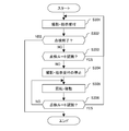
- FIG. 3 is a diagram illustrating a flow of processing for controlling the flying object 1 to fly along the inspection route projected on the structure 2. This process is started, for example, when the recognition unit 20 recognizes the inspection route.
- Step S301 The photographing unit 13 photographs an inspection image of the structure 2. That is, the photographing unit 13 photographs the inspection image when the recognition unit 20 recognizes the inspection route. Specifically, when the recognition unit 20 recognizes the inspection route, the photographing unit 13 captures the inspection route of the structure 2 or a moving image in which the periphery of the inspection route is included in the photographing range. Subsequently, the flight controller 11 receives the movement instruction from the operator and moves (flight controls) the flying object 1 along the inspection route recognized by the recognition unit 20. Then, the process proceeds to the process of step S302.
- Step S302 The flight controller 11 determines whether or not it has received an instruction from the pilot to end the inspection. Then, when the determination is affirmative, the process ends a series of processes shown in FIG. On the other hand, if the determination is negative, the process proceeds to the process of step S303.
- Step S303 The flight controller 11 determines whether or not the recognition unit 20 recognizes the inspection route projected on the structure 2. Then, when the determination is affirmative, the process proceeds to the process of step S301. On the other hand, if the determination is negative, the process proceeds to the process of step S304.
- Step S304 The photographing unit 13 stops taking an inspection image. Specifically, the photographing unit 13 stops photographing the inspection route of the structure 2 or the moving image in which the periphery of the inspection route is included in the photographing range. This makes it possible to reduce the trouble of editing the inspection video. Subsequently, the flight controller 11 stops accepting instructions from the pilot to move the flying object 1 along the inspection route. As a result, it is possible to prevent the part to be inspected from remaining in the inspection image. Then, the process proceeds to the process of step S305.
- Step S305 The flight controller 11 rotates and moves the flying object 1 in a predetermined direction at least.
- the flight controller 11 rotates and moves the flying object 1 perpendicular to the inspection route (direction of the line projected by the laser beam 4).
- the flight controller 11 recognizes that the color of the laser beam 4 recognized by the recognition unit 20 until just before is the color of the line extending in the vertical direction
- the flight controller 11 rotates the flying object 1 in the horizontal direction.
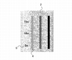
- FIG. 4 is a diagram showing an example in which the flying object 1 rotates and moves in the horizontal direction with respect to the laser beam 4 in the vertical direction. Then, the process proceeds to the process of step S306.
- Step S306 The flight controller 11 determines whether or not the recognition unit 20 recognizes the inspection route projected on the structure 2. Then, when the determination is affirmative, the process proceeds to the process of step S301. On the other hand, if the determination is negative, the process proceeds to the process of step S305.
- the flight controller 11 controls the flight body 1 so that the flight body 1 can shoot a stable inspection image along the inspection route.
- the photographing unit 13 and the recognition unit 20 have been described as separate functional units, but the photographing unit 13 and the recognition unit 20 may be configured by one device (for example, a camera).
- step S304 it has been described in step S304 that the reception of the instruction to move the flying object 1 from the operator along the inspection route is stopped, but the flight controller 11 has described the inspection route (laser light 4).
- the instruction to rotate and move the flying object 1 perpendicular to may be accepted.
- the flight controller 11 may stop shooting by the photographing unit 13 or the operator may stop shooting until the flight body 1 flies straight (horizontally). You may stop accepting instructions to move the aircraft 1 along the inspection route.
- the laser irradiation device 3 may be capable of projecting a plurality of patterns of inspection routes. As a result, the laser irradiation device 3 can project an inspection route of a pattern corresponding to the structure 2 which is an inspection target.
- the laser irradiation device 3 may project supplementary information other than the inspection route onto the structure 2 which is the inspection target.
- supplementary information for example, numerical values of distance and height, control points, and the like can be mentioned.
- FIG. 5 is a diagram showing an example in which supplementary information S is projected on the structure 2.
- a predetermined grid pattern may be irradiated to a predetermined position on the inspection target surface, and the current position may be estimated by recognizing the grid pattern as an image. That is, by acquiring the absolute position for irradiating the grid pattern, it is possible to estimate the self-position from the distance and the positional relationship from an arbitrary grid point. In this case, the position of the grid pattern on the inspection target surface is associated.
- the inspection image is a moving image
- it may be a still image
- the laser light 4 may be light that can be recognized by the recognition unit 20 and may not be photographed by the photographing unit 13 (for example, infrared rays). As a result, the laser beam 4 is not reflected in the inspection image, so that a portion to be inspected (for example, a crack in concrete) can be easily confirmed.
Landscapes
- Engineering & Computer Science (AREA)
- Aviation & Aerospace Engineering (AREA)
- Automation & Control Theory (AREA)
- Radar, Positioning & Navigation (AREA)
- Remote Sensing (AREA)
- Physics & Mathematics (AREA)
- General Physics & Mathematics (AREA)
- Control Of Position, Course, Altitude, Or Attitude Of Moving Bodies (AREA)
- Road Repair (AREA)
- Bridges Or Land Bridges (AREA)
- Lining And Supports For Tunnels (AREA)
- Optical Radar Systems And Details Thereof (AREA)
Applications Claiming Priority (2)
| Application Number | Priority Date | Filing Date | Title |
|---|---|---|---|
| JP2019073124A JP7278578B2 (ja) | 2019-04-05 | 2019-04-05 | 飛行体 |
| JP2019-073124 | 2019-04-05 |
Publications (1)
| Publication Number | Publication Date |
|---|---|
| WO2020204201A1 true WO2020204201A1 (ja) | 2020-10-08 |
Family
ID=72668476
Family Applications (1)
| Application Number | Title | Priority Date | Filing Date |
|---|---|---|---|
| PCT/JP2020/015437 Ceased WO2020204201A1 (ja) | 2019-04-05 | 2020-04-05 | 飛行体 |
Country Status (2)
| Country | Link |
|---|---|
| JP (3) | JP7278578B2 (enExample) |
| WO (1) | WO2020204201A1 (enExample) |
Cited By (1)
| Publication number | Priority date | Publication date | Assignee | Title |
|---|---|---|---|---|
| WO2022259799A1 (ja) * | 2021-06-09 | 2022-12-15 | 富士フイルム株式会社 | 制御装置、飛行体システム、制御方法、及びプログラム |
Families Citing this family (2)
| Publication number | Priority date | Publication date | Assignee | Title |
|---|---|---|---|---|
| JP7671615B2 (ja) * | 2021-04-08 | 2025-05-02 | 株式会社電通総研 | 自律移動物の配置最適化の方法、プログラム、および、システム |
| CN114302115B (zh) * | 2022-01-06 | 2024-04-19 | 重庆紫光华山智安科技有限公司 | 视频播放方法、装置、设备及介质 |
Citations (5)
| Publication number | Priority date | Publication date | Assignee | Title |
|---|---|---|---|---|
| JPS5968693A (ja) * | 1982-10-12 | 1984-04-18 | Hitachi Kiden Kogyo Ltd | 光ビ−ムを利用した移動体の追尾式誘導ならびに情報伝達装置 |
| JPH08101714A (ja) * | 1993-11-29 | 1996-04-16 | Toshihiro Tsumura | 飛行体の誘導装置 |
| US20160253808A1 (en) * | 2015-02-26 | 2016-09-01 | Hexagon Technology Center Gmbh | Determination of object data by template-based uav control |
| JP2017144784A (ja) * | 2016-02-15 | 2017-08-24 | 株式会社トプコン | 飛行計画作成方法及び飛行体誘導システム |
| WO2018034295A1 (ja) * | 2016-08-16 | 2018-02-22 | 本郷飛行機株式会社 | 情報処理システム |
Family Cites Families (10)
| Publication number | Priority date | Publication date | Assignee | Title |
|---|---|---|---|---|
| JP2009276166A (ja) * | 2008-05-14 | 2009-11-26 | Panasonic Corp | 移動装置および、その位置認識方法 |
| DE102010016208B4 (de) * | 2010-03-30 | 2022-09-22 | Vorwerk & Co. Interholding Gmbh | Verfahren zum Auffinden einer Fernbedienung |
| JP6509480B2 (ja) * | 2012-04-02 | 2019-05-08 | シャープ株式会社 | 照明装置 |
| US8793046B2 (en) * | 2012-06-01 | 2014-07-29 | Google Inc. | Inferring state of traffic signal and other aspects of a vehicle's environment based on surrogate data |
| WO2017150433A1 (ja) | 2016-03-02 | 2017-09-08 | 日本電気株式会社 | 無人航空機、無人航空機制御システム、飛行制御方法およびプログラム記憶媒体 |
| JP2017174159A (ja) | 2016-03-24 | 2017-09-28 | 日本電気株式会社 | 無人飛行装置制御システム、無人飛行装置制御方法および画像投影装置 |
| JP2018133010A (ja) * | 2017-02-17 | 2018-08-23 | 三菱重工業株式会社 | 屋内空間の検査方法 |
| JP2018143463A (ja) | 2017-03-03 | 2018-09-20 | 学校法人日本大学 | 投射装置 |
| JP7022559B2 (ja) | 2017-10-17 | 2022-02-18 | 株式会社トプコン | 無人航空機の制御方法および無人航空機の制御用プログラム |
| US20220126456A1 (en) | 2019-02-19 | 2022-04-28 | Nec Corporation | Robot, robot operating method, and non- transitory computer-readable medium |
-
2019
- 2019-04-05 JP JP2019073124A patent/JP7278578B2/ja active Active
-
2020
- 2020-04-05 WO PCT/JP2020/015437 patent/WO2020204201A1/ja not_active Ceased
-
2023
- 2023-04-28 JP JP2023074374A patent/JP7504502B2/ja active Active
-
2024
- 2024-06-05 JP JP2024091112A patent/JP2024113070A/ja active Pending
Patent Citations (5)
| Publication number | Priority date | Publication date | Assignee | Title |
|---|---|---|---|---|
| JPS5968693A (ja) * | 1982-10-12 | 1984-04-18 | Hitachi Kiden Kogyo Ltd | 光ビ−ムを利用した移動体の追尾式誘導ならびに情報伝達装置 |
| JPH08101714A (ja) * | 1993-11-29 | 1996-04-16 | Toshihiro Tsumura | 飛行体の誘導装置 |
| US20160253808A1 (en) * | 2015-02-26 | 2016-09-01 | Hexagon Technology Center Gmbh | Determination of object data by template-based uav control |
| JP2017144784A (ja) * | 2016-02-15 | 2017-08-24 | 株式会社トプコン | 飛行計画作成方法及び飛行体誘導システム |
| WO2018034295A1 (ja) * | 2016-08-16 | 2018-02-22 | 本郷飛行機株式会社 | 情報処理システム |
Cited By (3)
| Publication number | Priority date | Publication date | Assignee | Title |
|---|---|---|---|---|
| WO2022259799A1 (ja) * | 2021-06-09 | 2022-12-15 | 富士フイルム株式会社 | 制御装置、飛行体システム、制御方法、及びプログラム |
| US20240103538A1 (en) * | 2021-06-09 | 2024-03-28 | Fujifilm Corporation | Control device, flying object system, control method, and program |
| US12461541B2 (en) * | 2021-06-09 | 2025-11-04 | Fujifilm Corporation | Control device, flying object system, control method, and program |
Also Published As
| Publication number | Publication date |
|---|---|
| JP7278578B2 (ja) | 2023-05-22 |
| JP2024113070A (ja) | 2024-08-21 |
| JP7504502B2 (ja) | 2024-06-24 |
| JP2020169010A (ja) | 2020-10-15 |
| JP2023113608A (ja) | 2023-08-16 |
Similar Documents
| Publication | Publication Date | Title |
|---|---|---|
| JP7504502B2 (ja) | 飛行体 | |
| CN109074101B (zh) | 使用多个无人机的成像 | |
| JP6601554B2 (ja) | 無人航空機、無人航空機制御システム、飛行制御方法およびコンピュータプログラム | |
| JP6371988B2 (ja) | 飛行体 | |
| US20170045895A1 (en) | Selective processing of sensor data | |
| US20190113937A1 (en) | Measuring device, control device for unmanned aerial vehicle and computer program product for controlling unmanned aerial vehicle | |
| CN106444843A (zh) | 无人机相对方位控制方法及装置 | |
| JP6812667B2 (ja) | 無人飛行装置制御システム、無人飛行装置制御方法および無人飛行装置 | |
| JP6140458B2 (ja) | 自律移動ロボット | |
| CN112327898B (zh) | 无人机的井道巡检导航方法、装置和无人机 | |
| JP2025016555A (ja) | 位置算出方法及び情報処理システム | |
| JP6957304B2 (ja) | 架線撮影システム及び架線撮影方法 | |
| JP2019211257A (ja) | 検査システム | |
| JP2021100234A (ja) | 飛行体の撮像方法及び情報処理装置 | |
| WO2021166845A1 (ja) | 情報処理装置、情報処理方法、及びプログラム | |
| WO2020042159A1 (zh) | 一种云台的转动控制方法、装置及控制设备、移动平台 | |
| AU2021391392B2 (en) | Method for controlling a drone along a shaft | |
| JP2019211486A (ja) | 検査システム | |
| JP2023070120A (ja) | 自律飛行制御方法、自律飛行制御装置および自律飛行制御システム | |
| WO2017138049A1 (ja) | 飛行体及びその制御システム | |
| JP7149569B2 (ja) | 建造物の測定方法 | |
| JP2024159828A (ja) | 飛行体、点検方法及び点検システム | |
| WO2021124579A1 (ja) | 飛行体の撮像方法及び情報処理装置 | |
| JP2020161143A (ja) | 飛行体、点検方法及び点検システム | |
| JP2020201849A (ja) | 飛行体の制御方法 |
Legal Events
| Date | Code | Title | Description |
|---|---|---|---|
| 121 | Ep: the epo has been informed by wipo that ep was designated in this application |
Ref document number: 20784895 Country of ref document: EP Kind code of ref document: A1 |
|
| NENP | Non-entry into the national phase |
Ref country code: DE |
|
| 122 | Ep: pct application non-entry in european phase |
Ref document number: 20784895 Country of ref document: EP Kind code of ref document: A1 |