WO2020203851A1 - ショベル - Google Patents
ショベル Download PDFInfo
- Publication number
- WO2020203851A1 WO2020203851A1 PCT/JP2020/014224 JP2020014224W WO2020203851A1 WO 2020203851 A1 WO2020203851 A1 WO 2020203851A1 JP 2020014224 W JP2020014224 W JP 2020014224W WO 2020203851 A1 WO2020203851 A1 WO 2020203851A1
- Authority
- WO
- WIPO (PCT)
- Prior art keywords
- bucket
- boom
- control
- controller
- weight
- Prior art date
Links
Images


Classifications
-
- G—PHYSICS
- G01—MEASURING; TESTING
- G01G—WEIGHING
- G01G19/00—Weighing apparatus or methods adapted for special purposes not provided for in the preceding groups
- G01G19/08—Weighing apparatus or methods adapted for special purposes not provided for in the preceding groups for incorporation in vehicles
- G01G19/083—Weighing apparatus or methods adapted for special purposes not provided for in the preceding groups for incorporation in vehicles lift truck scale
-
- E—FIXED CONSTRUCTIONS
- E02—HYDRAULIC ENGINEERING; FOUNDATIONS; SOIL SHIFTING
- E02F—DREDGING; SOIL-SHIFTING
- E02F3/00—Dredgers; Soil-shifting machines
- E02F3/04—Dredgers; Soil-shifting machines mechanically-driven
- E02F3/28—Dredgers; Soil-shifting machines mechanically-driven with digging tools mounted on a dipper- or bucket-arm, i.e. there is either one arm or a pair of arms, e.g. dippers, buckets
- E02F3/36—Component parts
- E02F3/42—Drives for dippers, buckets, dipper-arms or bucket-arms
- E02F3/43—Control of dipper or bucket position; Control of sequence of drive operations
- E02F3/435—Control of dipper or bucket position; Control of sequence of drive operations for dipper-arms, backhoes or the like
-
- E—FIXED CONSTRUCTIONS
- E02—HYDRAULIC ENGINEERING; FOUNDATIONS; SOIL SHIFTING
- E02F—DREDGING; SOIL-SHIFTING
- E02F9/00—Component parts of dredgers or soil-shifting machines, not restricted to one of the kinds covered by groups E02F3/00 - E02F7/00
- E02F9/20—Drives; Control devices
- E02F9/22—Hydraulic or pneumatic drives
- E02F9/2221—Control of flow rate; Load sensing arrangements
-
- E—FIXED CONSTRUCTIONS
- E02—HYDRAULIC ENGINEERING; FOUNDATIONS; SOIL SHIFTING
- E02F—DREDGING; SOIL-SHIFTING
- E02F3/00—Dredgers; Soil-shifting machines
- E02F3/04—Dredgers; Soil-shifting machines mechanically-driven
- E02F3/28—Dredgers; Soil-shifting machines mechanically-driven with digging tools mounted on a dipper- or bucket-arm, i.e. there is either one arm or a pair of arms, e.g. dippers, buckets
- E02F3/30—Dredgers; Soil-shifting machines mechanically-driven with digging tools mounted on a dipper- or bucket-arm, i.e. there is either one arm or a pair of arms, e.g. dippers, buckets with a dipper-arm pivoted on a cantilever beam, i.e. boom
- E02F3/32—Dredgers; Soil-shifting machines mechanically-driven with digging tools mounted on a dipper- or bucket-arm, i.e. there is either one arm or a pair of arms, e.g. dippers, buckets with a dipper-arm pivoted on a cantilever beam, i.e. boom working downwardly and towards the machine, e.g. with backhoes
-
- E—FIXED CONSTRUCTIONS
- E02—HYDRAULIC ENGINEERING; FOUNDATIONS; SOIL SHIFTING
- E02F—DREDGING; SOIL-SHIFTING
- E02F3/00—Dredgers; Soil-shifting machines
- E02F3/04—Dredgers; Soil-shifting machines mechanically-driven
- E02F3/28—Dredgers; Soil-shifting machines mechanically-driven with digging tools mounted on a dipper- or bucket-arm, i.e. there is either one arm or a pair of arms, e.g. dippers, buckets
- E02F3/36—Component parts
- E02F3/42—Drives for dippers, buckets, dipper-arms or bucket-arms
- E02F3/43—Control of dipper or bucket position; Control of sequence of drive operations
- E02F3/435—Control of dipper or bucket position; Control of sequence of drive operations for dipper-arms, backhoes or the like
- E02F3/437—Control of dipper or bucket position; Control of sequence of drive operations for dipper-arms, backhoes or the like providing automatic sequences of movements, e.g. linear excavation, keeping dipper angle constant
-
- E—FIXED CONSTRUCTIONS
- E02—HYDRAULIC ENGINEERING; FOUNDATIONS; SOIL SHIFTING
- E02F—DREDGING; SOIL-SHIFTING
- E02F9/00—Component parts of dredgers or soil-shifting machines, not restricted to one of the kinds covered by groups E02F3/00 - E02F7/00
- E02F9/20—Drives; Control devices
- E02F9/2025—Particular purposes of control systems not otherwise provided for
- E02F9/2029—Controlling the position of implements in function of its load, e.g. modifying the attitude of implements in accordance to vehicle speed
-
- E—FIXED CONSTRUCTIONS
- E02—HYDRAULIC ENGINEERING; FOUNDATIONS; SOIL SHIFTING
- E02F—DREDGING; SOIL-SHIFTING
- E02F9/00—Component parts of dredgers or soil-shifting machines, not restricted to one of the kinds covered by groups E02F3/00 - E02F7/00
- E02F9/20—Drives; Control devices
- E02F9/22—Hydraulic or pneumatic drives
- E02F9/2221—Control of flow rate; Load sensing arrangements
- E02F9/2225—Control of flow rate; Load sensing arrangements using pressure-compensating valves
- E02F9/2228—Control of flow rate; Load sensing arrangements using pressure-compensating valves including an electronic controller
-
- E—FIXED CONSTRUCTIONS
- E02—HYDRAULIC ENGINEERING; FOUNDATIONS; SOIL SHIFTING
- E02F—DREDGING; SOIL-SHIFTING
- E02F9/00—Component parts of dredgers or soil-shifting machines, not restricted to one of the kinds covered by groups E02F3/00 - E02F7/00
- E02F9/20—Drives; Control devices
- E02F9/22—Hydraulic or pneumatic drives
- E02F9/2264—Arrangements or adaptations of elements for hydraulic drives
- E02F9/2267—Valves or distributors
-
- E—FIXED CONSTRUCTIONS
- E02—HYDRAULIC ENGINEERING; FOUNDATIONS; SOIL SHIFTING
- E02F—DREDGING; SOIL-SHIFTING
- E02F9/00—Component parts of dredgers or soil-shifting machines, not restricted to one of the kinds covered by groups E02F3/00 - E02F7/00
- E02F9/20—Drives; Control devices
- E02F9/22—Hydraulic or pneumatic drives
- E02F9/2264—Arrangements or adaptations of elements for hydraulic drives
- E02F9/2271—Actuators and supports therefor and protection therefor
-
- E—FIXED CONSTRUCTIONS
- E02—HYDRAULIC ENGINEERING; FOUNDATIONS; SOIL SHIFTING
- E02F—DREDGING; SOIL-SHIFTING
- E02F9/00—Component parts of dredgers or soil-shifting machines, not restricted to one of the kinds covered by groups E02F3/00 - E02F7/00
- E02F9/20—Drives; Control devices
- E02F9/22—Hydraulic or pneumatic drives
- E02F9/2278—Hydraulic circuits
- E02F9/2292—Systems with two or more pumps
-
- E—FIXED CONSTRUCTIONS
- E02—HYDRAULIC ENGINEERING; FOUNDATIONS; SOIL SHIFTING
- E02F—DREDGING; SOIL-SHIFTING
- E02F9/00—Component parts of dredgers or soil-shifting machines, not restricted to one of the kinds covered by groups E02F3/00 - E02F7/00
- E02F9/20—Drives; Control devices
- E02F9/22—Hydraulic or pneumatic drives
- E02F9/2278—Hydraulic circuits
- E02F9/2296—Systems with a variable displacement pump
-
- E—FIXED CONSTRUCTIONS
- E02—HYDRAULIC ENGINEERING; FOUNDATIONS; SOIL SHIFTING
- E02F—DREDGING; SOIL-SHIFTING
- E02F9/00—Component parts of dredgers or soil-shifting machines, not restricted to one of the kinds covered by groups E02F3/00 - E02F7/00
- E02F9/26—Indicating devices
-
- E—FIXED CONSTRUCTIONS
- E02—HYDRAULIC ENGINEERING; FOUNDATIONS; SOIL SHIFTING
- E02F—DREDGING; SOIL-SHIFTING
- E02F9/00—Component parts of dredgers or soil-shifting machines, not restricted to one of the kinds covered by groups E02F3/00 - E02F7/00
- E02F9/26—Indicating devices
- E02F9/261—Surveying the work-site to be treated
- E02F9/262—Surveying the work-site to be treated with follow-up actions to control the work tool, e.g. controller
-
- E—FIXED CONSTRUCTIONS
- E02—HYDRAULIC ENGINEERING; FOUNDATIONS; SOIL SHIFTING
- E02F—DREDGING; SOIL-SHIFTING
- E02F9/00—Component parts of dredgers or soil-shifting machines, not restricted to one of the kinds covered by groups E02F3/00 - E02F7/00
- E02F9/26—Indicating devices
- E02F9/264—Sensors and their calibration for indicating the position of the work tool
- E02F9/265—Sensors and their calibration for indicating the position of the work tool with follow-up actions (e.g. control signals sent to actuate the work tool)
-
- F—MECHANICAL ENGINEERING; LIGHTING; HEATING; WEAPONS; BLASTING
- F15—FLUID-PRESSURE ACTUATORS; HYDRAULICS OR PNEUMATICS IN GENERAL
- F15B—SYSTEMS ACTING BY MEANS OF FLUIDS IN GENERAL; FLUID-PRESSURE ACTUATORS, e.g. SERVOMOTORS; DETAILS OF FLUID-PRESSURE SYSTEMS, NOT OTHERWISE PROVIDED FOR
- F15B11/00—Servomotor systems without provision for follow-up action; Circuits therefor
- F15B11/02—Systems essentially incorporating special features for controlling the speed or actuating force of an output member
-
- F—MECHANICAL ENGINEERING; LIGHTING; HEATING; WEAPONS; BLASTING
- F15—FLUID-PRESSURE ACTUATORS; HYDRAULICS OR PNEUMATICS IN GENERAL
- F15B—SYSTEMS ACTING BY MEANS OF FLUIDS IN GENERAL; FLUID-PRESSURE ACTUATORS, e.g. SERVOMOTORS; DETAILS OF FLUID-PRESSURE SYSTEMS, NOT OTHERWISE PROVIDED FOR
- F15B11/00—Servomotor systems without provision for follow-up action; Circuits therefor
- F15B11/16—Servomotor systems without provision for follow-up action; Circuits therefor with two or more servomotors
-
- G—PHYSICS
- G01—MEASURING; TESTING
- G01G—WEIGHING
- G01G19/00—Weighing apparatus or methods adapted for special purposes not provided for in the preceding groups
- G01G19/08—Weighing apparatus or methods adapted for special purposes not provided for in the preceding groups for incorporation in vehicles
-
- G—PHYSICS
- G01—MEASURING; TESTING
- G01M—TESTING STATIC OR DYNAMIC BALANCE OF MACHINES OR STRUCTURES; TESTING OF STRUCTURES OR APPARATUS, NOT OTHERWISE PROVIDED FOR
- G01M1/00—Testing static or dynamic balance of machines or structures
- G01M1/12—Static balancing; Determining position of centre of gravity
- G01M1/122—Determining position of centre of gravity
-
- E—FIXED CONSTRUCTIONS
- E02—HYDRAULIC ENGINEERING; FOUNDATIONS; SOIL SHIFTING
- E02F—DREDGING; SOIL-SHIFTING
- E02F9/00—Component parts of dredgers or soil-shifting machines, not restricted to one of the kinds covered by groups E02F3/00 - E02F7/00
- E02F9/20—Drives; Control devices
- E02F9/22—Hydraulic or pneumatic drives
- E02F9/2278—Hydraulic circuits
- E02F9/2285—Pilot-operated systems
Definitions
- This disclosure relates to excavators.
- a shovel that includes a boom angle meter that detects the angle between the boom and the upper body, an arm angle meter that detects the angle between the boom and the arm, and a stroke meter that detects the stroke of the bucket cylinder, and detects the weight of earth and sand in the bucket is disclosed. (See Patent Document 1).
- an attachment attached to the upper swing body and a control device are provided, and the control device estimates the center of gravity of the load loaded on the attachment.
- a shovel is provided that includes an estimation unit and a weight calculation unit that calculates the weight of the load based on the estimated center of gravity of the load.
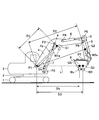
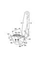
- FIG. 1 is a side view of the excavator 100 as an excavator according to the present embodiment.
- the excavator 100 is located on a horizontal plane facing the uphill slope ES to be constructed, and is an uphill slope BS (that is, after construction on the uphill slope ES, which is an example of the target construction surface described later. Slope shape) is also described.
- the uphill slope ES to be constructed is provided with a cylindrical body (not shown) indicating the normal direction of the uphill slope BS, which is the target construction surface.
- the excavator 100 includes a lower traveling body 1, an upper swinging body 3 mounted on the lower traveling body 1 so as to be swivelable via a swivel mechanism 2, a boom 4 and an arm constituting an attachment (working machine). It includes 5, a bucket 6, and a cabin 10.
- the lower traveling body 1 travels the excavator 100 by hydraulically driving a pair of left and right crawlers with traveling hydraulic motors 1L and 1R (see FIG. 2 described later), respectively. That is, the pair of traveling hydraulic motors 1L and 1R (an example of the traveling motor) drive the lower traveling body 1 (crawler) as the driven portion.
- the upper swing body 3 turns with respect to the lower traveling body 1 by being driven by the swing hydraulic motor 2A (see FIG. 2 described later). That is, the swing hydraulic motor 2A is a swing drive unit that drives the upper swing body 3 as a driven unit, and can change the direction of the upper swing body 3.
- the upper swing body 3 may be electrically driven by an electric motor (hereinafter, "swivel motor”) instead of the swing hydraulic motor 2A. That is, the swivel motor is a swivel drive unit that drives the upper swivel body 3 as a non-drive unit, like the swivel hydraulic motor 2A, and can change the direction of the upper swivel body 3.
- swivel motor is a swivel drive unit that drives the upper swivel body 3 as a non-drive unit, like the swivel hydraulic motor 2A, and can change the direction of the upper swivel body 3.
- the boom 4 is pivotally attached to the center of the front portion of the upper swing body 3 so as to be vertically movable
- the arm 5 is pivotally attached to the tip of the boom 4 so as to be vertically rotatable
- the tip of the arm 5 is pivotally attached as an end attachment.
- the bucket 6 is pivotally attached so as to be vertically rotatable.
- the boom 4, arm 5, and bucket 6 are hydraulically driven by the boom cylinder 7, arm cylinder 8, and bucket cylinder 9 as hydraulic actuators, respectively.
- the bucket 6 is an example of an end attachment, and the tip of the arm 5 has another end attachment, for example, a slope bucket, a dredging bucket, or a breaker, instead of the bucket 6 depending on the work content or the like. Etc. may be attached.
- the cabin 10 is a driver's cab on which the operator is boarded, and is mounted on the front left side of the upper swing body 3.
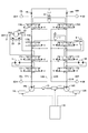
- FIG. 2 is a diagram schematically showing an example of the configuration of the excavator 100 according to the present embodiment.
- FIG. 2 the mechanical power system, the hydraulic oil line, the pilot line, and the electric control system are shown by double lines, solid lines, broken lines, and dotted lines, respectively.
- the drive system of the excavator 100 includes an engine 11, a regulator 13, a main pump 14, and a control valve 17. Further, as described above, the hydraulic drive system of the excavator 100 according to the present embodiment hydraulically drives each of the lower traveling body 1, the upper rotating body 3, the boom 4, the arm 5, and the bucket 6 traveling hydraulic motors 1L, 1R. , Swirling hydraulic motor 2A, boom cylinder 7, arm cylinder 8, bucket cylinder 9, and other hydraulic actuators.
- the engine 11 is the main power source in the hydraulic drive system, and is mounted on the rear part of the upper swing body 3, for example. Specifically, the engine 11 rotates constantly at a preset target rotation speed under direct or indirect control by a controller 30, which will be described later, to drive the main pump 14 and the pilot pump 15.
- the engine 11 is, for example, a diesel engine that uses light oil as fuel.
- the regulator 13 controls the discharge amount of the main pump 14. For example, the regulator 13 adjusts the angle (tilt angle) of the swash plate of the main pump 14 in response to a control command from the controller 30.
- the regulator 13 includes regulators 13L and 13R, for example, as described later.
- the main pump 14 is mounted on the rear part of the upper swing body 3 like the engine 11, and supplies hydraulic oil to the control valve 17 through the high-pressure hydraulic line.
- the main pump 14 is driven by the engine 11 as described above.
- the main pump 14 is, for example, a variable displacement hydraulic pump, and as described above, the stroke length of the piston is adjusted by adjusting the tilt angle of the swash plate by the regulator 13 under the control of the controller 30, and the pump is discharged.
- the flow rate (discharge pressure) is controlled.
- the main pump 14 includes, for example, the main pumps 14L and 14R as described later.
- the control valve 17 is, for example, a hydraulic control device mounted in the central portion of the upper swing body 3 and controls the hydraulic drive system in response to an operator's operation on the operating device 26.
- the control valve 17 is connected to the main pump 14 via the high-pressure hydraulic line, and the hydraulic oil supplied from the main pump 14 is supplied to the hydraulic actuator (running hydraulic motor 1L) according to the operating state of the operating device 26. , 1R, swing hydraulic motor 2A, boom cylinder 7, arm cylinder 8, and bucket cylinder 9) are selectively supplied.
- the control valve 17 includes control valves 171 to 176 that control the flow rate and flow direction of the hydraulic oil supplied from the main pump 14 to each of the hydraulic actuators.
- control valve 171 corresponds to the traveling hydraulic motor 1L
- control valve 172 corresponds to the traveling hydraulic motor 1R
- control valve 173 corresponds to the swing hydraulic motor 2A
- control valve 174 corresponds to the bucket cylinder 9
- control valve 175 corresponds to the boom cylinder 7
- the control valve 176 corresponds to the arm cylinder 8.
- control valve 175 includes, for example, control valves 175L and 175R as described later
- control valve 176 includes, for example, control valves 176L and 176R as described later. Details of the control valves 171 to 176 will be described later.
- the operating system of the excavator 100 includes the pilot pump 15 and the operating device 26. Further, the operation system of the excavator 100 includes a shuttle valve 32 as a configuration related to a machine control function by the controller 30, which will be described later.
- the pilot pump 15 is mounted on the rear part of the upper swing body 3, for example, and supplies the pilot pressure to the operating device 26 via the pilot line.
- the pilot pump 15 is, for example, a fixed-capacity hydraulic pump, and is driven by the engine 11 as described above.
- the operation device 26 is provided near the driver's seat of the cabin 10, and is an operation input means for the operator to operate various operation elements (lower traveling body 1, upper turning body 3, boom 4, arm 5, bucket 6, etc.). Is. In other words, the operating device 26 operates the hydraulic actuators (that is, traveling hydraulic motors 1L, 1R, swivel hydraulic motor 2A, boom cylinder 7, arm cylinder 8, bucket cylinder 9, etc.) in which the operator drives each operating element. It is an operation input means for performing.
- the operating device 26 is connected to the control valve 17 directly through the pilot line on the secondary side thereof or indirectly via the shuttle valve 32 described later provided on the pilot line on the secondary side.
- the operating device 26 includes, for example, a lever device for operating the arm 5 (arm cylinder 8). Further, the operating device 26 includes, for example, lever devices 26A to 26C for operating each of the boom 4 (boom cylinder 7), the bucket 6 (bucket cylinder 9), and the upper swing body 3 (swing hydraulic motor 2A) (FIG. 4A). See ⁇ 4C). Further, the operating device 26 includes, for example, a lever device and a pedal device for operating each of the pair of left and right crawlers (traveling hydraulic motors 1L, 1R) of the lower traveling body 1.
- the shuttle valve 32 has two inlet ports and one outlet port, and outputs hydraulic oil having the higher pilot pressure of the pilot pressures input to the two inlet ports to the outlet port.
- one of the two inlet ports is connected to the operating device 26 and the other is connected to the proportional valve 31.
- the outlet port of the shuttle valve 32 is connected through the pilot line to the pilot port of the corresponding control valve in the control valve 17 (see FIGS. 4A-4C for details). Therefore, the shuttle valve 32 can make the higher of the pilot pressure generated by the operating device 26 and the pilot pressure generated by the proportional valve 31 act on the pilot port of the corresponding control valve.
- the controller 30, which will be described later, outputs a pilot pressure higher than the pilot pressure on the secondary side output from the operating device 26 from the proportional valve 31, so that the corresponding control is performed regardless of the operation of the operating device 26 by the operator. It is possible to control the valve and control the operation of various operating elements.
- the shuttle valve 32 includes, for example, shuttle valves 32AL, 32AR, 32BL, 32BR, 32CL, 32CR as described later.
- the operating device 26 (left operating lever, right operating lever, left traveling lever, and right traveling lever) may be an electric type that outputs an electric signal instead of a hydraulic pilot type that outputs a pilot pressure.
- the electric signal from the operating device 26 is input to the controller 30, and the controller 30 controls each of the control valves 171 to 176 in the control valve 17 according to the input electric signal.
- the operation of various hydraulic actuators is realized according to the operation content with respect to 26.
- the control valves 171 to 176 in the control valve 17 may be electromagnetic solenoid type spool valves driven by a command from the controller 30.
- an electromagnetic valve that operates in response to an electric signal from the controller 30 may be arranged between the pilot pump 15 and the pilot ports of the control valves 171 to 176.
- the controller 30 controls the solenoid valve by an electric signal corresponding to the operation amount (for example, the lever operation amount) to increase or decrease the pilot pressure.
- the operation amount for example, the lever operation amount
- Spool displacement sensors 181 to 186 for detecting the displacement amount of the spool are attached to each of the control valves 171 to 176.
- the spool displacement sensor 184 detects the displacement amount of the spool of the control valve 174.
- the detection signal corresponding to the displacement amount of the spool by the spool displacement sensors 181 to 186 is taken into the controller 30.
- the control system of the excavator 100 includes a controller 30, a discharge pressure sensor 28, an operating pressure sensor 29, a proportional valve 31, a display device 40, an input device 42, an audio output device 43, and storage.
- the device 47, a boom angle sensor S1, an arm angle sensor S2, a machine body tilt sensor S4, a turning state sensor S5, an image pickup device S6, a positioning device P0, and a communication device T1 are included.
- the controller 30 (an example of a control device) is provided in the cabin 10, for example, and controls the drive of the excavator 100.
- the function of the controller 30 may be realized by any hardware, software, or a combination thereof.
- the controller 30 is centered on a microcomputer including a CPU (Central Processing Unit), a ROM (Read Only Memory), a RAM (Random Access Memory), a non-volatile auxiliary storage device, and various input / output interfaces. It is composed.
- the controller 30 realizes various functions by executing various programs stored in a ROM or a non-volatile auxiliary storage device on the CPU, for example.
- the controller 30 sets a target rotation speed based on a work mode or the like preset by a predetermined operation of an operator or the like, and performs drive control for rotating the engine 11 at a constant speed.
- controller 30 outputs a control command to the regulator 13 as needed to change the discharge amount of the main pump 14.
- the controller 30 controls the machine guidance function for guiding the manual operation of the excavator 100 through the operating device 26 by the operator, for example. Further, the controller 30 controls, for example, a machine control function that automatically supports the manual operation of the excavator 100 through the operating device 26 by the operator. That is, the controller 30 includes the machine guidance unit 50 as a functional unit related to the machine guidance function and the machine control function. Further, the controller 30 includes a sediment load processing unit 60, which will be described later.
- controller 30 may be realized by another controller (control device). That is, the function of the controller 30 may be realized in a manner distributed by a plurality of controllers.
- the machine guidance function and the machine control function may be realized by a dedicated controller (control device).
- the discharge pressure sensor 28 detects the discharge pressure of the main pump 14.
- the detection signal corresponding to the discharge pressure detected by the discharge pressure sensor 28 is taken into the controller 30.
- the discharge pressure sensor 28 includes, for example, discharge pressure sensors 28L and 28R as described later.
- the operating pressure sensor 29 has a pilot pressure on the secondary side of the operating device 26, that is, an operating state (for example, an operating direction, an operating amount, etc.) relating to each operating element (that is, a hydraulic actuator) in the operating device 26.
- the pilot pressure corresponding to the operation content) is detected.
- the pilot pressure detection signal corresponding to the operating state of the lower traveling body 1, the upper swinging body 3, the boom 4, the arm 5, the bucket 6 and the like in the operating device 26 by the operating pressure sensor 29 is taken into the controller 30.
- the operating pressure sensor 29 includes, for example, operating pressure sensors 29A to 29C as described later.
- the operating pressure sensor 29 it is possible to detect the operating amount (tilting amount) and tilting direction of other sensors capable of detecting the operating state of each operating element in the operating device 26, for example, the lever devices 26A to 26C.
- An encoder, a potentiometer, or the like may be provided.
- the proportional valve 31 is provided in the pilot line connecting the pilot pump 15 and the shuttle valve 32, and is configured so that the flow path area (cross-sectional area through which hydraulic oil can flow) can be changed.
- the proportional valve 31 operates in response to a control command input from the controller 30.
- the controller 30 can supply the hydraulic oil discharged from the pilot pump 15 to the proportional valve 31 and the proportional valve 31 even when the operating device 26 (specifically, the lever devices 26A to 26C) is not operated by the operator. It can be supplied to the pilot port of the corresponding control valve in the control valve 17 via the shuttle valve 32.
- the proportional valve 31 includes, for example, proportional valves 31AL, 31AR, 31BL, 31BR, 31CL, 31CR as described later.
- the display device 40 is provided in the cabin 10 at a location that is easily visible to the seated operator, and displays various information images under the control of the controller 30.
- the display device 40 may be connected to the controller 30 via an in-vehicle communication network such as CAN (Controller Area Network), or may be connected to the controller 30 via a one-to-one dedicated line.
- CAN Controller Area Network
- the input device 42 is provided within reach of the seated operator in the cabin 10, receives various operation inputs by the operator, and outputs a signal corresponding to the operation input to the controller 30.
- the input device 42 includes a touch panel mounted on a display of a display device that displays various information images, a knob switch provided at the tip of a lever portion of lever devices 26A to 26C, a button switch installed around the display device 40, and a lever. , Toggle, rotary dial, etc.
- the signal corresponding to the operation content for the input device 42 is taken into the controller 30.
- the voice output device 43 is provided in the cabin 10, for example, is connected to the controller 30, and outputs voice under the control of the controller 30.
- the audio output device 43 is, for example, a speaker, a buzzer, or the like.
- the voice output device 43 outputs various information by voice in response to a voice output command from the controller 30.
- the storage device 47 is provided in the cabin 10, for example, and stores various information under the control of the controller 30.
- the storage device 47 is a non-volatile storage medium such as a semiconductor memory.
- the storage device 47 may store information output by various devices during the operation of the excavator 100, or may store information acquired through the various devices before the operation of the excavator 100 is started.
- the storage device 47 may store data regarding the target construction surface acquired via the communication device T1 or the like or set through the input device 42 or the like, for example.
- the target construction surface may be set (saved) by the operator of the excavator 100, or may be set by the construction manager or the like.
- the boom angle sensor S1 is attached to the boom 4, and the depression / elevation angle of the boom 4 with respect to the upper swing body 3 (hereinafter, “boom angle”), for example, in a side view, the boom 4 has a swing plane of the upper swing body 3. Detects the angle formed by the straight line connecting the fulcrums at both ends.
- the boom angle sensor S1 may include, for example, a rotary encoder, an acceleration sensor, a 6-axis sensor, an IMU (Inertial Measurement Unit), and the like.
- the boom angle sensor S1 may include a potentiometer using a variable resistor, a cylinder sensor for detecting the stroke amount of the hydraulic cylinder (boom cylinder 7) corresponding to the boom angle, and the like.
- the detection signal corresponding to the boom angle by the boom angle sensor S1 is taken into the controller 30.
- the arm angle sensor S2 is attached to the arm 5, and the rotation angle of the arm 5 with respect to the boom 4 (hereinafter, “arm angle”), for example, the arm 5 with respect to a straight line connecting the fulcrums at both ends of the boom 4 in a side view. Detects the angle formed by the straight line connecting the fulcrums at both ends of. The detection signal corresponding to the arm angle by the arm angle sensor S2 is taken into the controller 30.
- the excavator 100 is attached to the bucket 6, and the rotation angle of the bucket 6 with respect to the arm 5 (hereinafter, “bucket angle”), for example, a straight line connecting the fulcrums at both ends of the arm 5 in a side view.
- bucket angle the rotation angle of the bucket 6 with respect to the arm 5
- the bucket angle sensor that detects the angle formed by the straight line connecting the fulcrum of the bucket 6 and the tip (blade edge) is not required.
- the airframe tilt sensor S4 detects the tilted state of the airframe (upper swivel body 3 or lower traveling body 1) with respect to the horizontal plane.
- the airframe tilt sensor S4 is attached to, for example, the upper swing body 3, and tilt angles around two axes in the front-rear direction and the left-right direction of the excavator 100 (that is, the upper swing body 3) (hereinafter, “front-back tilt angle” and “left-right”. Tilt angle ”) is detected.
- the airframe tilt sensor S4 may include, for example, a rotary encoder, an acceleration sensor, a 6-axis sensor, an IMU, and the like.
- the detection signal corresponding to the tilt angle (front-back tilt angle and left-right tilt angle) by the aircraft tilt sensor S4 is taken into the controller 30.
- the turning state sensor S5 outputs detection information regarding the turning state of the upper swing body 3.
- the turning state sensor S5 detects, for example, the turning angular velocity and the turning angle of the upper swing body 3.
- the swivel state sensor S5 may include, for example, a gyro sensor, a resolver, a rotary encoder, and the like.
- the detection signal corresponding to the turning angle and the turning angular velocity of the upper turning body 3 by the turning state sensor S5 is taken into the controller 30.
- the imaging device S6 as a space recognition device images the periphery of the excavator 100.
- the image pickup apparatus S6 includes a camera S6F that images the front of the excavator 100, a camera S6L that images the left side of the excavator 100, a camera S6R that images the right side of the excavator 100, and a camera S6B that images the rear of the excavator 100. ..
- the camera S6F is mounted on the ceiling of the cabin 10, that is, inside the cabin 10, for example. Further, the camera S6F may be attached to the outside of the cabin 10, such as the roof of the cabin 10 and the side surface of the boom 4.
- the camera S6L is attached to the upper left end of the upper swivel body 3
- the camera S6R is attached to the upper right end of the upper swivel body 3
- the camera S6B is attached to the upper surface rear end of the upper swivel body 3.
- the image pickup apparatus S6 (cameras S6F, S6B, S6L, S6R) is, for example, a monocular wide-angle camera having a very wide angle of view. Further, the image pickup device S6 may be a stereo camera, a distance image camera, or the like. The image captured by the image pickup device S6 is captured by the controller 30 via the display device 40.
- the image pickup device S6 as a space recognition device may function as an object detection device.
- the image pickup apparatus S6 may detect an object existing around the excavator 100.
- the object to be detected may include, for example, a person, an animal, a vehicle, a construction machine, a building, a hole, or the like. Further, the image pickup device S6 may calculate the distance from the image pickup device S6 or the excavator 100 to the recognized object.
- the image pickup device S6 as the object detection device may include, for example, a stereo camera, a distance image sensor, and the like.
- the space recognition device is, for example, a monocular camera having an image sensor such as a CCD or CMOS, and outputs the captured image to the display device 40.
- the space recognition device may be configured to calculate the distance from the space recognition device or the excavator 100 to the recognized object.
- other object detection devices such as an ultrasonic sensor, a millimeter wave radar, a lidar, and an infrared sensor may be provided as the space recognition device.
- a millimeter-wave radar, an ultrasonic sensor, a laser radar, or the like is used as a space recognition device, a large number of signals (laser light, etc.) are transmitted to an object, and the reflected signal is received, so that the object is converted from the reflected signal. Distance and direction may be detected.
- image pickup device S6 may be directly connected to the controller 30 so as to be communicable.
- a boom rod pressure sensor S7R and a boom bottom pressure sensor S7B are attached to the boom cylinder 7.
- An arm rod pressure sensor S8R and an arm bottom pressure sensor S8B are attached to the arm cylinder 8.
- a bucket rod pressure sensor S9R and a bucket bottom pressure sensor S9B are attached to the bucket cylinder 9.
- the boom rod pressure sensor S7R, boom bottom pressure sensor S7B, arm rod pressure sensor S8R, arm bottom pressure sensor S8B, bucket rod pressure sensor S9R and bucket bottom pressure sensor S9B are also collectively referred to as "cylinder pressure sensor”.
- the boom rod pressure sensor S7R detects the pressure in the rod side oil chamber of the boom cylinder 7 (hereinafter referred to as “boom rod pressure”), and the boom bottom pressure sensor S7B detects the pressure in the bottom side oil chamber of the boom cylinder 7 (hereinafter referred to as “boom rod pressure”). , “Boom bottom pressure”) is detected.
- the arm rod pressure sensor S8R detects the pressure in the rod side oil chamber of the arm cylinder 8 (hereinafter referred to as “arm rod pressure”), and the arm bottom pressure sensor S8B detects the pressure in the bottom side oil chamber of the arm cylinder 8 (hereinafter referred to as “arm rod pressure”). , "Arm bottom pressure”) is detected.
- the bucket rod pressure sensor S9R detects the pressure in the rod side oil chamber of the bucket cylinder 9 (hereinafter referred to as “bucket rod pressure”), and the bucket bottom pressure sensor S9B detects the pressure in the bottom side oil chamber of the bucket cylinder 9 (hereinafter referred to as “bucket rod pressure”). , “Bucket bottom pressure”) is detected.
- the positioning device P0 measures the position and orientation of the upper swing body 3.
- the positioning device P0 is, for example, a GNSS (Global Navigation Satellite System) compass, detects the position and orientation of the upper swing body 3, and captures the detection signal corresponding to the position and orientation of the upper swing body 3 into the controller 30. .. Further, among the functions of the positioning device P0, the function of detecting the direction of the upper swing body 3 may be replaced by the azimuth sensor attached to the upper swing body 3.
- GNSS Global Navigation Satellite System
- the communication device T1 communicates with an external device through a predetermined network including a mobile communication network having a base station as a terminal, a satellite communication network, an Internet network, and the like.
- the communication device T1 is, for example, a mobile communication module corresponding to mobile communication standards such as LTE (LongTermEvolution), 4G (4thGeneration), and 5G (5thGeneration), and satellite communication for connecting to a satellite communication network. Modules, etc.
- the machine guidance unit 50 controls the excavator 100 regarding the machine guidance function, for example.
- the machine guidance unit 50 conveys work information such as the distance between the target construction surface and the tip of the attachment, specifically, the work part of the end attachment, to the operator through the display device 40, the voice output device 43, or the like. ..
- the data regarding the target construction surface is stored in advance in the storage device 47, for example, as described above.
- the data regarding the target construction surface is represented by, for example, a reference coordinate system.
- the reference coordinate system is, for example, the world geodetic system.
- the world geodetic system is a three-dimensional orthogonal coordinate with the origin at the center of the earth, the X-axis in the direction of the intersection of the Greenwich meridian and the equator, the Y-axis in the direction of 90 degrees east longitude, and the Z-axis in the direction of the North Pole. It is an XYZ coordinate system.
- the operator may set an arbitrary point on the construction site as a reference point, and set the target construction surface through the input device 42 according to the relative positional relationship with the reference point.
- the working part of the bucket 6 is, for example, the toe of the bucket 6, the back surface of the bucket 6, and the like.
- the tip portion of the breaker corresponds to the work part.
- the machine guidance unit 50 notifies the operator of work information through the display device 40, the voice output device 43, and the like, and guides the operator to operate the excavator 100 through the operation device 26.
- the machine guidance unit 50 executes control of the excavator 100 regarding the machine control function, for example.
- the machine guidance unit 50 is, for example, at least one of the boom 4, the arm 5, and the bucket 6 so that the target construction surface and the tip position of the bucket 6 are aligned when the operator is manually performing the excavation operation. One may be operated automatically.
- the machine guidance unit 50 acquires information from the boom angle sensor S1, the arm angle sensor S2, the machine body tilt sensor S4, the turning state sensor S5, the image pickup device S6, the positioning device P0, the communication device T1, the input device 42, and the like. Then, the machine guidance unit 50 calculates, for example, the distance between the bucket 6 and the target construction surface based on the acquired information, and the bucket is based on the sound from the sound output device 43 and the image displayed on the display device 40. Notify the operator of the degree of distance between 6 and the target construction surface, and make sure that the tip of the attachment (specifically, the work part such as the toe or back of the bucket 6) matches the target construction surface. Automatically control the operation of attachments.
- the machine guidance unit 50 has a position calculation unit 51, a distance calculation unit 52, an information transmission unit 53, an automatic control unit 54, and a turning angle calculation unit 55 as detailed functional configurations related to the machine guidance function and the machine control function. And the relative angle calculation unit 56.
- the position calculation unit 51 calculates the position of a predetermined positioning target. For example, the position calculation unit 51 calculates the coordinate points in the reference coordinate system of the tip portion of the attachment, specifically, the work portion such as the toe or the back surface of the bucket 6. Specifically, the position calculation unit 51 calculates the coordinate points of the working portion of the bucket 6 from the elevation angles (boom angle, arm angle, and bucket angle) of the boom 4, the arm 5, and the bucket 6.
- the elevation angles boost angle, arm angle, and bucket angle
- the distance calculation unit 52 calculates the distance between two positioning targets. For example, the distance calculation unit 52 calculates the distance between the tip of the attachment, specifically, the work site such as the tip of the bucket 6 or the back surface, and the target construction surface. Further, the distance calculation unit 52 may calculate an angle (relative angle) between the back surface of the bucket 6 as a work portion and the target construction surface.
- the information transmission unit 53 transmits (notifies) various information to the operator of the excavator 100 through a predetermined notification means such as the display device 40 and the voice output device 43.
- the information transmission unit 53 notifies the operator of the excavator 100 of the magnitude (degree) of various distances and the like calculated by the distance calculation unit 52.
- the distance (magnitude) between the tip of the bucket 6 and the target construction surface is transmitted to the operator by using at least one of the visual information by the display device 40 and the auditory information by the audio output device 43.
- the information transmission unit 53 uses at least one of the visual information by the display device 40 and the auditory information by the audio output device 43, and the relative angle (large) between the back surface of the bucket 6 as a work part and the target construction surface. You may tell the operator.
- the information transmission unit 53 informs the operator of the magnitude of the distance (for example, the vertical distance) between the work part of the bucket 6 and the target construction surface by using the intermittent sound generated by the voice output device 43.
- the information transmission unit 53 may shorten the interval of the intermittent sound as the vertical distance becomes smaller, and lengthen the sensation of the intermittent sound as the vertical distance increases.
- the information transmission unit 53 may use continuous sound, and may express the difference in the magnitude of the vertical distance while changing the pitch, strength, etc. of the sound.
- the information transmission unit 53 may issue an alarm through the voice output device 43 when the tip end portion of the bucket 6 is at a position lower than the target construction surface, that is, when the target construction surface is exceeded.
- the alarm is, for example, a continuous sound that is significantly louder than the intermittent sound.
- the information transmission unit 53 is the tip portion of the attachment, specifically, the size of the distance between the work part of the bucket 6 and the target construction surface, and the relative angle between the back surface of the bucket 6 and the target construction surface.
- the size and the like may be displayed on the display device 40 as work information.
- the display device 40 displays, for example, the work information received from the information transmission unit 53 together with the image data received from the image pickup device S6.
- the information transmission unit 53 may transmit the magnitude of the vertical distance to the operator by using, for example, an image of an analog meter or an image of a bar graph indicator.
- the automatic control unit 54 automatically supports the manual operation of the excavator 100 through the operation device 26 by the operator by automatically operating the actuator.
- the automatic control unit 54 is a control valve (specifically, specifically, a swivel hydraulic motor 2A, a boom cylinder 7, and a bucket cylinder 9) corresponding to a plurality of hydraulic actuators (specifically, a swing hydraulic motor 2A, a boom cylinder 7, and a bucket cylinder 9) as described later.
- the pilot pressure acting on the control valve 173, the control valves 175L, 175R, and the control valve 174) can be adjusted individually and automatically. As a result, the automatic control unit 54 can automatically operate each hydraulic actuator.
- the control related to the machine control function by the automatic control unit 54 may be executed, for example, when a predetermined switch included in the input device 42 is pressed.
- the predetermined switch is, for example, a machine control switch (hereinafter, “MC (Machine Control) switch”), and is a grip portion by an operator of an operating device 26 (for example, a lever device corresponding to the operation of the arm 5) as a knob switch. It may be arranged at the tip of.
- MC Machine Control
- the automatic control unit 54 automatically switches at least one of the boom cylinder 7 and the bucket cylinder 9 in accordance with the operation of the arm cylinder 8 in order to support the excavation work and the shaping work. Expand and contract.
- the automatic control unit 54 has a target construction surface and a work part such as a toe or a back surface of the bucket 6.
- At least one of the boom cylinder 7 and the bucket cylinder 9 is automatically expanded and contracted so as to match the position of. In this case, for example, the operator can close the arm 5 while aligning the toes of the bucket 6 with the target construction surface by simply operating the lever device corresponding to the operation of the arm 5.
- the automatic control unit 54 may automatically rotate the swing hydraulic motor 2A (an example of an actuator) in order to make the upper swing body 3 face the target construction surface when the MC switch or the like is pressed. ..
- the control by the controller 30 (automatic control unit 54) to make the upper swing body 3 face the target construction surface is referred to as "face-to-face control".
- the operator or the like can target the upper swivel body 3 by simply pressing a predetermined switch, or by operating the lever device 26C described later corresponding to the swivel operation while the switch is pressed. It can be made to face the surface. Further, the operator can make the upper swivel body 3 face the target construction surface and start the machine control function related to the excavation work of the target construction surface described above by simply pressing the MC switch.
- the tip of the attachment (for example, the tip of the toe or the back surface of the bucket 6 as a work part) is set to the target construction surface (for example, according to the operation of the attachment). It is in a state where it can be moved along the inclination direction of the ascending slope BS).
- the operating surface of the attachment (attachment operating surface) vertical to the swivel plane of the excavator 100 corresponds to the target construction surface. It is a state including the normal of the surface (in other words, a state along the normal).
- the automatic control unit 54 can automatically rotate the swing hydraulic motor 2A to face the upper swing body 3. As a result, the excavator 100 can appropriately construct the target construction surface.
- the automatic control unit 54 determines, for example, the leftmost vertical distance between the leftmost coordinate point of the toe of the bucket 6 and the target construction surface (hereinafter, simply “leftmost vertical distance") and the toe of the bucket 6.
- the rightmost vertical distance between the rightmost coordinate point and the target construction surface hereinafter, simply “rightmost vertical distance” becomes equal, it is judged that the excavator faces the target construction surface.
- the automatic control unit 54 is not when the leftmost vertical distance and the rightmost vertical distance are equal (that is, when the difference between the leftmost vertical distance and the rightmost vertical distance becomes zero), but the difference is equal to or less than a predetermined value. When becomes, it may be determined that the excavator 100 faces the target construction surface.
- the automatic control unit 54 may operate the swing hydraulic motor 2A in the face-to-face control, for example, based on the difference between the leftmost vertical distance and the rightmost vertical distance. Specifically, when the lever device 26C corresponding to the turning operation is operated while a predetermined switch such as the MC switch is pressed, the lever device 26C moves in the direction in which the upper turning body 3 faces the target construction surface. Determine if it has been manipulated. For example, when the lever device 26C is operated in the direction in which the vertical distance between the toe of the bucket 6 and the target construction surface (uphill slope BS) increases, the automatic control unit 54 does not execute the facing control.
- a predetermined switch such as the MC switch
- the automatic control unit 54 executes the facing control.
- the automatic control unit 54 can operate the swing hydraulic motor 2A so that the difference between the leftmost vertical distance and the rightmost vertical distance becomes small.
- the automatic control unit 54 stops the swing hydraulic motor 2A.
- the automatic control unit 54 sets a turning angle at which the difference is equal to or less than a predetermined value or becomes zero as a target angle, and is based on the target angle and the current turning angle (specifically, the detection signal of the turning state sensor S5).
- the operation of the swing hydraulic motor 2A may be controlled so that the angle difference from the detected value) becomes zero.
- the turning angle is, for example, the angle of the front-rear axis of the upper turning body 3 with respect to the reference direction.
- the automatic control unit 54 performs face-to-face control with the swing motor (an example of an actuator) as a control target. ..
- the turning angle calculation unit 55 calculates the turning angle of the upper turning body 3. As a result, the controller 30 can specify the current orientation of the upper swing body 3.
- the turning angle calculation unit 55 calculates, for example, the angle of the front-rear axis of the upper turning body 3 with respect to the reference direction as the turning angle based on the output signal of the GNSS compass included in the positioning device P0. Further, the turning angle calculation unit 55 may calculate the turning angle based on the detection signal of the turning state sensor S5. Further, when the reference point is set at the construction site, the turning angle calculation unit 55 may use the direction in which the reference point is viewed from the turning axis as the reference direction.
- the turning angle indicates the direction in which the attachment operating surface extends with respect to the reference direction.
- the attachment operating surface is, for example, a virtual plane that vertically traverses the attachment, and is arranged so as to be perpendicular to the turning plane.
- the swivel plane is, for example, a virtual plane including the bottom surface of the swivel frame perpendicular to the swivel axis.
- the relative angle calculation unit 56 calculates the turning angle (relative angle) required for the upper swivel body 3 to face the target construction surface.
- the relative angle is formed between, for example, the direction of the front-rear axis of the upper swivel body 3 when the upper swivel body 3 faces the target construction surface and the current direction of the front-rear axis of the upper swivel body 3. Relative angle.
- the relative angle calculation unit 56 calculates the relative angle based on, for example, the data on the target construction surface stored in the storage device 47 and the turning angle calculated by the turning angle calculation unit 55.
- the automatic control unit 54 When the lever device 26C corresponding to the turning operation is operated while a predetermined switch such as the MC switch is pressed, the automatic control unit 54 is turned in the direction in which the upper turning body 3 faces the target construction surface. Judge whether or not. When the automatic control unit 54 determines that the upper swivel body 3 has been swiveled in the direction facing the target construction surface, the automatic control unit 54 sets the relative angle calculated by the relative angle calculation unit 56 as the target angle. Then, when the change in the turning angle after the lever device 26C is operated reaches the target angle, the automatic control unit 54 determines that the upper turning body 3 faces the target construction surface, and determines that the turning hydraulic motor 2A You may stop the movement.
- the automatic control unit 54 can make the upper swing body 3 face the target construction surface on the premise of the configuration shown in FIG.
- face-to-face control an example of face-to-face control with respect to the target construction surface is shown, but the present invention is not limited to this.
- a target excavation track corresponding to the target volume is generated, and a turning operation is performed so that the attachment faces the target excavation track.
- the target excavation track is changed each time the scooping operation is performed. Therefore, after the soil is discharged to the dump truck DT, it is directly controlled against the newly changed target excavation track.
- the swing hydraulic motor 2A has a first port 2A1 and a second port 2A2.
- the hydraulic sensor 21 detects the pressure of the hydraulic oil in the first port 2A1 of the swing hydraulic motor 2A.
- the hydraulic pressure sensor 22 detects the pressure of the hydraulic oil in the second port 2A2 of the swing hydraulic motor 2A.
- the detection signal corresponding to the discharge pressure detected by the hydraulic sensors 21 and 22 is taken into the controller 30.
- first port 2A1 is connected to the hydraulic oil tank via the relief valve 23.
- the relief valve 23 opens when the pressure on the first port 2A1 side reaches a predetermined relief pressure, and discharges the hydraulic oil on the first port 2A1 side to the hydraulic oil tank.
- the second port 2A2 is connected to the hydraulic oil tank via the relief valve 24.
- the relief valve 24 opens when the pressure on the second port 2A2 side reaches a predetermined relief pressure, and discharges the hydraulic oil on the second port 2A2 side to the hydraulic oil tank.
- FIG. 3 is a diagram schematically showing an example of the configuration of the hydraulic system of the excavator 100 according to the present embodiment.
- the hydraulic system realized by the hydraulic circuit circulates hydraulic oil from the main pumps 14L and 14R driven by the engine 11 to the hydraulic oil tank via the center bypass oil passages C1L and C1R and the parallel oil passages C2L and C2R, respectively. Let me.
- the center bypass oil passage C1L starts from the main pump 14L, passes through the control valves 171, 173, 175L, and 176L arranged in the control valve 17 in order, and reaches the hydraulic oil tank.
- the center bypass oil passage C1R starts from the main pump 14R, passes through the control valves 172, 174, 175R, and 176R arranged in the control valve 17 in order, and reaches the hydraulic oil tank.
- the control valve 171 is a spool valve that supplies the hydraulic oil discharged from the main pump 14L to the traveling hydraulic motor 1L and discharges the hydraulic oil discharged from the traveling hydraulic motor 1L to the hydraulic oil tank.
- the control valve 172 is a spool valve that supplies the hydraulic oil discharged from the main pump 14R to the traveling hydraulic motor 1R and discharges the hydraulic oil discharged from the traveling hydraulic motor 1R to the hydraulic oil tank.
- the control valve 173 is a spool valve that supplies the hydraulic oil discharged from the main pump 14L to the swing hydraulic motor 2A and discharges the hydraulic oil discharged by the swing hydraulic motor 2A to the hydraulic oil tank.
- the control valve 174 is a spool valve that supplies the hydraulic oil discharged from the main pump 14R to the bucket cylinder 9 and discharges the hydraulic oil in the bucket cylinder 9 to the hydraulic oil tank.
- the control valves 175L and 175R are spool valves that supply the hydraulic oil discharged by the main pumps 14L and 14R to the boom cylinder 7 and discharge the hydraulic oil in the boom cylinder 7 to the hydraulic oil tank, respectively.
- the control valves 176L and 176R supply the hydraulic oil discharged by the main pumps 14L and 14R to the arm cylinder 8 and discharge the hydraulic oil in the arm cylinder 8 to the hydraulic oil tank.
- the control valves 171, 172, 173, 174, 175L, 175R, 176L, and 176R adjust the flow rate of the hydraulic oil supplied to and discharged from the hydraulic actuator according to the pilot pressure acting on the pilot port, and the flow direction, respectively. To switch.
- the parallel oil passage C2L supplies the hydraulic oil of the main pump 14L to the control valves 171, 173, 175L, and 176L in parallel with the center bypass oil passage C1L.
- the parallel oil passage C2L branches from the center bypass oil passage C1L on the upstream side of the control valve 171 and supplies the hydraulic oil of the main pump 14L in parallel with the control valves 171, 173, 175L, and 176R, respectively. It is configured to be possible.
- the parallel oil passage C2L supplies the hydraulic oil to the control valve further downstream when the flow of the hydraulic oil through the center bypass oil passage C1L is restricted or blocked by any of the control valves 171, 173, and 175L. it can.
- the parallel oil passage C2R supplies the hydraulic oil of the main pump 14R to the control valves 172, 174, 175R and 176R in parallel with the center bypass oil passage C1R.
- the parallel oil passage C2R branches from the center bypass oil passage C1R on the upstream side of the control valve 172, and supplies the hydraulic oil of the main pump 14R in parallel with the control valves 172, 174, 175R, and 176R, respectively. It is configured to be possible.
- the parallel oil passage C2R can supply the hydraulic oil to the control valve further downstream when the flow of the hydraulic oil through the center bypass oil passage C1R is restricted or blocked by any of the control valves 172, 174, and 175R.
- the regulators 13L and 13R adjust the discharge amount of the main pumps 14L and 14R by adjusting the tilt angle of the swash plate of the main pumps 14L and 14R, respectively, under the control of the controller 30.
- the discharge pressure sensor 28L detects the discharge pressure of the main pump 14L, and the detection signal corresponding to the detected discharge pressure is taken into the controller 30. The same applies to the discharge pressure sensor 28R. As a result, the controller 30 can control the regulators 13L and 13R according to the discharge pressures of the main pumps 14L and 14R.
- Negative control throttles (hereinafter referred to as “negative control throttles”) 18L and 18R are provided between the most downstream control valves 176L and 176R and the hydraulic oil tank in the center bypass oil passages C1L and C1R. As a result, the flow of hydraulic oil discharged by the main pumps 14L and 14R is restricted by the negative control throttles 18L and 18R. Then, the negative control diaphragms 18L and 18R generate a control pressure (hereinafter, “negative control pressure”) for controlling the regulators 13L and 13R.
- negative control pressure hereinafter, “negative control pressure”
- the negative control pressure sensors 19L and 19R detect the negative control pressure, and the detection signal corresponding to the detected negative control pressure is taken into the controller 30.
- the controller 30 may control the regulators 13L and 13R according to the discharge pressures of the main pumps 14L and 14R detected by the discharge pressure sensors 28L and 28R, and adjust the discharge amount of the main pumps 14L and 14R. For example, the controller 30 may reduce the discharge amount by controlling the regulator 13L in response to the increase in the discharge pressure of the main pump 14L and adjusting the swash plate tilt angle of the main pump 14L. The same applies to the regulator 13R. As a result, the controller 30 controls the total horsepower of the main pumps 14L and 14R so that the absorbed horsepower of the main pumps 14L and 14R, which is represented by the product of the discharge pressure and the discharge amount, does not exceed the output horsepower of the engine 11. be able to.
- the controller 30 may adjust the discharge amount of the main pumps 14L and 14R by controlling the regulators 13L and 13R according to the negative control pressure detected by the negative control pressure sensors 19L and 19R. For example, the controller 30 reduces the discharge amount of the main pumps 14L and 14R as the negative control pressure increases, and increases the discharge amount of the main pumps 14L and 14R as the negative control pressure decreases.
- the hydraulic oil discharged from the main pumps 14L and 14R passes through the center bypass oil passages C1L and C1R. Through it, it reaches the negative control aperture 18L, 18R. Then, the flow of the hydraulic oil discharged from the main pumps 14L and 14R increases the negative control pressure generated upstream of the negative control throttles 18L and 18R. As a result, the controller 30 reduces the discharge amount of the main pumps 14L and 14R to the allowable minimum discharge amount, and suppresses the pressure loss (pumping loss) when the discharged hydraulic oil passes through the center bypass oil passages C1L and C1R. ..
- the hydraulic oil discharged from the main pumps 14L and 14R is sent to the hydraulic actuator to be operated via the control valve corresponding to the hydraulic actuator to be operated. It flows in. Then, the flow of hydraulic oil discharged from the main pumps 14L and 14R reduces or eliminates the amount reaching the negative control diaphragms 18L and 18R, and lowers the negative control pressure generated upstream of the negative control throttles 18L and 18R. As a result, the controller 30 can increase the discharge amount of the main pumps 14L and 14R, circulate sufficient hydraulic oil to the hydraulic actuator to be operated, and reliably drive the hydraulic actuator to be operated.
- FIG. 4A to 4C are diagrams schematically showing an example of a component related to an operation system in the hydraulic system of the excavator 100 according to the present embodiment.
- FIG. 4A is a diagram showing an example of a pilot circuit in which a pilot pressure is applied to the control valves 175L and 175R that hydraulically control the boom cylinder 7.
- FIG. 4B is a diagram showing an example of a pilot circuit in which a pilot pressure is applied to a control valve 174 that hydraulically controls the bucket cylinder 9.
- FIG. 4C is a diagram showing an example of a pilot circuit in which a pilot pressure is applied to a control valve 173 that hydraulically controls the swing hydraulic motor 2A.
- the lever device 26A is used by an operator or the like to operate the boom cylinder 7 corresponding to the boom 4.
- the lever device 26A uses the hydraulic oil discharged from the pilot pump 15 to output the pilot pressure according to the operation content to the secondary side.
- the two inlet ports are the pilot line on the secondary side of the lever device 26A corresponding to the operation in the raising direction of the boom 4 (hereinafter, “boom raising operation”), and the secondary of the proportional valve 31AL.
- the outlet port is connected to the pilot port on the right side of the control valve 175L and the pilot port on the left side of the control valve 175R.
- the two inlet ports are the pilot line on the secondary side of the lever device 26A corresponding to the operation in the lowering direction of the boom 4 (hereinafter, “boom lowering operation”), and the secondary of the proportional valve 31AR. It is connected to the pilot line on the side and the outlet port is connected to the pilot port on the right side of the control valve 175R.
- the lever device 26A applies a pilot pressure according to the operation content (for example, the operation direction and the operation amount) to the pilot ports of the control valves 175L and 175R via the shuttle valves 32AL and 32AR. Specifically, the lever device 26A outputs a pilot pressure according to the amount of operation to one inlet port of the shuttle valve 32AL when the boom is raised, and the right side of the control valve 175L via the shuttle valve 32AL. It acts on the pilot port of the above and the pilot port on the left side of the control valve 175R.
- the operation content for example, the operation direction and the operation amount
- the lever device 26A when the boom lowering operation is performed, the lever device 26A outputs the pilot pressure according to the operation amount to one inlet port of the shuttle valve 32AR, and the pilot port on the right side of the control valve 175R via the shuttle valve 32AR. To act on.
- the proportional valve 31AL operates according to the control current input from the controller 30. Specifically, the proportional valve 31AL uses the hydraulic oil discharged from the pilot pump 15 to output a pilot pressure corresponding to the control current input from the controller 30 to the other inlet port of the shuttle valve 32AL. Thereby, the proportional valve 31AL can adjust the pilot pressure acting on the pilot port on the right side of the control valve 175L and the pilot port on the left side of the control valve 175R via the shuttle valve 32AL.
- the proportional valve 31AR operates according to the control current input from the controller 30. Specifically, the proportional valve 31AR uses the hydraulic oil discharged from the pilot pump 15 to output a pilot pressure corresponding to the control current input from the controller 30 to the other inlet port of the shuttle valve 32AR. As a result, the proportional valve 31AR can adjust the pilot pressure acting on the pilot port on the right side of the control valve 175R via the shuttle valve 32AR.
- the proportional valves 31AL and 31AR can adjust the pilot pressure output to the secondary side so that the control valves 175L and 175R can be stopped at an arbitrary valve position regardless of the operating state of the lever device 26A.
- the proportional valve 33AL functions as a machine control control valve in the same manner as the proportional valve 31AL.
- the proportional valve 33AL is arranged in a pipeline connecting the operating device 26 and the shuttle valve 32AL, and is configured so that the flow path area of the pipeline can be changed.
- the proportional valve 33AL operates in response to a control command output from the controller 30. Therefore, the controller 30 reduces the pressure of the hydraulic oil discharged by the operating device 26 regardless of the operation of the operating device 26 by the operator, and then passes the shuttle valve 32AL to the corresponding control valve in the control valve 17. Can be supplied to the pilot port of.
- the proportional valve 33AR functions as a control valve for machine control.
- the proportional valve 33AR is arranged in a pipeline connecting the operating device 26 and the shuttle valve 32AR, and is configured so that the flow path area of the pipeline can be changed.
- the proportional valve 33AR operates in response to a control command output from the controller 30. Therefore, the controller 30 reduces the pressure of the hydraulic oil discharged by the operating device 26 regardless of the operation of the operating device 26 by the operator, and then passes the corresponding control valve in the control valve 17 via the shuttle valve 32AR. Can be supplied to the pilot port of.
- the operating pressure sensor 29A detects the operation content of the lever device 26A by the operator in the form of pressure (operating pressure), and the detection signal corresponding to the detected pressure is taken into the controller 30. As a result, the controller 30 can grasp the operation content for the lever device 26A.
- the controller 30 controls the hydraulic oil discharged from the pilot pump 15 to the pilot port on the right side of the control valve 175L via the proportional valve 31AL and the shuttle valve 32AL, regardless of the boom raising operation on the lever device 26A by the operator. It can be supplied to the pilot port on the left side of the valve 175R. Further, the controller 30 supplies the hydraulic oil discharged from the pilot pump 15 to the pilot port on the right side of the control valve 175R via the proportional valve 31AR and the shuttle valve 32AR, regardless of the boom lowering operation of the lever device 26A by the operator. Can be supplied to. That is, the controller 30 can automatically control the raising and lowering operation of the boom 4. Further, the controller 30 can forcibly stop the operation of the hydraulic actuator corresponding to the specific operating device 26 even when the operation on the specific operating device 26 is being performed.
- the proportional valve 33AL operates in response to a control command (current command) output by the controller 30. Then, the pilot pressure due to the hydraulic oil introduced from the pilot pump 15 to the right side pilot port of the control valve 175L and the left side pilot port of the control valve 175R is reduced via the lever device 26A, the proportional valve 33AL, and the shuttle valve 32AL.
- the proportional valve 33AR operates in response to a control command (current command) output by the controller 30. Then, the pilot pressure due to the hydraulic oil introduced from the pilot pump 15 to the right pilot port of the control valve 175R via the lever device 26A, the proportional valve 33AR, and the shuttle valve 32AR is reduced.
- the proportional valves 33AL and 33AR can adjust the pilot pressure so that the control valves 175L and 175R can be stopped at any valve position.
- the controller 30 can use the pilot port on the raising side of the control valve 175 (the left pilot port of the control valve 175L and the control valve, if necessary, even when the boom raising operation is performed by the operator.
- the pilot pressure acting on the right pilot port of the 175R) can be reduced to forcibly stop the closing operation of the boom 4. The same applies to the case where the lowering operation of the boom 4 is forcibly stopped while the boom lowering operation is being performed by the operator.
- the controller 30 controls the proportional valve 31AR as necessary even when the boom raising operation is performed by the operator, and is on the opposite side of the pilot port on the raising side of the control valve 175.
- the controller 30 controls the proportional valve 31AR as necessary even when the boom raising operation is performed by the operator, and is on the opposite side of the pilot port on the raising side of the control valve 175.
- the lever device 26B is used by an operator or the like to operate the bucket cylinder 9 corresponding to the bucket 6.
- the lever device 26B uses the hydraulic oil discharged from the pilot pump 15 to output the pilot pressure according to the operation content to the secondary side.
- the two inlet ports are the pilot line on the secondary side of the lever device 26B corresponding to the operation in the closing direction of the bucket 6 (hereinafter, “bucket closing operation”), and the secondary of the proportional valve 31BL. It is connected to the pilot line on the side and the outlet port is connected to the pilot port on the left side of the control valve 174.
- the two inlet ports are the pilot line on the secondary side of the lever device 26B corresponding to the operation in the opening direction of the bucket 6 (hereinafter, “bucket opening operation”), and the secondary of the proportional valve 31BR. It is connected to the pilot line on the side and the outlet port is connected to the pilot port on the right side of the control valve 174.
- the lever device 26B exerts a pilot pressure according to the operation content on the pilot port of the control valve 174 via the shuttle valves 32BL and 32BR. Specifically, when the bucket is closed, the lever device 26B outputs a pilot pressure according to the amount of operation to one inlet port of the shuttle valve 32BL, and via the shuttle valve 32BL, the left side of the control valve 174. Act on the pilot port of. Further, when the bucket is opened, the lever device 26B outputs a pilot pressure according to the amount of operation to one inlet port of the shuttle valve 32BR, and via the shuttle valve 32BR, the pilot port on the right side of the control valve 174. To act on.
- the proportional valve 31BL operates according to the control current input from the controller 30. Specifically, the proportional valve 31BL uses the hydraulic oil discharged from the pilot pump 15 to output a pilot pressure corresponding to the control current input from the controller 30 to the other pilot port of the shuttle valve 32BL. Thereby, the proportional valve 31BL can adjust the pilot pressure acting on the pilot port on the left side of the control valve 174 via the shuttle valve 32BL.
- the proportional valve 31BR operates according to the control current output by the controller 30. Specifically, the proportional valve 31BR uses the hydraulic oil discharged from the pilot pump 15 to output a pilot pressure corresponding to the control current input from the controller 30 to the other pilot port of the shuttle valve 32BR. Thereby, the proportional valve 31BR can adjust the pilot pressure acting on the pilot port on the right side of the control valve 174 via the shuttle valve 32BR.
- the proportional valves 31BL and 31BR can adjust the pilot pressure output to the secondary side so that the control valve 174 can be stopped at an arbitrary valve position regardless of the operating state of the lever device 26B.
- the proportional valve 33BL functions as a machine control control valve in the same manner as the proportional valve 31BL.
- the proportional valve 33BL is arranged in a pipeline connecting the operating device 26 and the shuttle valve 32BL, and is configured so that the flow path area of the pipeline can be changed.
- the proportional valve 33BL operates in response to a control command output from the controller 30. Therefore, the controller 30 reduces the pressure of the hydraulic oil discharged by the operating device 26 regardless of the operation of the operating device 26 by the operator, and then passes the shuttle valve 32BL to the corresponding control valve in the control valve 17. Can be supplied to the pilot port of.
- the proportional valve 33BR functions as a control valve for machine control.
- the proportional valve 33BR is arranged in a pipeline connecting the operating device 26 and the shuttle valve 32BR, and is configured so that the flow path area of the pipeline can be changed.
- the proportional valve 33BR operates in response to a control command output from the controller 30. Therefore, the controller 30 reduces the pressure of the hydraulic oil discharged by the operating device 26 regardless of the operation of the operating device 26 by the operator, and then passes the corresponding control valve in the control valve 17 via the shuttle valve 32BR. Can be supplied to the pilot port of.
- the operating pressure sensor 29B detects the operation content of the lever device 26B by the operator in the form of pressure (operating pressure), and the detection signal corresponding to the detected pressure is taken into the controller 30. As a result, the controller 30 can grasp the operation content of the lever device 26B.
- the controller 30 supplies the hydraulic oil discharged from the pilot pump 15 to the pilot port on the left side of the control valve 174 via the proportional valve 31BL and the shuttle valve 32BL, regardless of the bucket closing operation on the lever device 26B by the operator. Can be made to. Further, the controller 30 supplies the hydraulic oil discharged from the pilot pump 15 to the pilot port on the right side of the control valve 174 via the proportional valve 31BR and the shuttle valve 32BR regardless of the bucket opening operation for the lever device 26B by the operator. Can be supplied to. That is, the controller 30 can automatically control the opening / closing operation of the bucket 6. Further, the controller 30 can forcibly stop the operation of the hydraulic actuator corresponding to the specific operating device 26 even when the operation on the specific operating device 26 is being performed.
- the operation of the proportional valves 33BL and 33BR for forcibly stopping the operation of the bucket 6 when the bucket closing operation or the bucket opening operation is performed by the operator is performed by the operator performing a boom raising operation or a boom lowering operation. This is the same as the operation of the proportional valves 33AL and 33AR for forcibly stopping the operation of the boom 4 when the boom 4 is broken, and duplicate description will be omitted.
- the lever device 26C is used by an operator or the like to operate the swing hydraulic motor 2A corresponding to the upper swing body 3 (swing mechanism 2).
- the lever device 26C uses the hydraulic oil discharged from the pilot pump 15 to output the pilot pressure according to the operation content to the secondary side.
- the two inlet ports are the pilot line on the secondary side of the lever device 26C corresponding to the left turning operation of the upper turning body 3 (hereinafter, “left turning operation”), and the proportional valve 31CL. It is connected to the pilot line on the secondary side of the control valve 173, and the outlet port is connected to the pilot port on the left side of the control valve 173.
- the two inlet ports are the pilot line on the secondary side of the lever device 26C corresponding to the rightward turning operation of the upper turning body 3 (hereinafter, “right turning operation”), and the proportional valve. It is connected to the pilot line on the secondary side of 31CR, and the outlet port is connected to the pilot port on the right side of the control valve 173.
- the lever device 26C applies a pilot pressure according to the operation content in the left-right direction to the pilot port of the control valve 173 via the shuttle valves 32CL and 32CR. Specifically, when the lever device 26C is turned left, the pilot pressure corresponding to the amount of operation is output to one inlet port of the shuttle valve 32CL, and the left side of the control valve 173 is output via the shuttle valve 32CL. Act on the pilot port of. Further, when the lever device 26C is turned to the right, the pilot pressure according to the amount of operation is output to one inlet port of the shuttle valve 32CR, and the pilot on the right side of the control valve 173 via the shuttle valve 32CR. Act on the port.
- the proportional valve 31CL operates according to the control current input from the controller 30. Specifically, the proportional valve 31CL uses the hydraulic oil discharged from the pilot pump 15 to output a pilot pressure corresponding to the control current input from the controller 30 to the other pilot port of the shuttle valve 32CL. As a result, the proportional valve 31CL can adjust the pilot pressure acting on the pilot port on the left side of the control valve 173 via the shuttle valve 32CL.
- the proportional valve 31CR operates according to the control current output by the controller 30. Specifically, the proportional valve 31CR uses the hydraulic oil discharged from the pilot pump 15 to output a pilot pressure corresponding to the control current input from the controller 30 to the other pilot port of the shuttle valve 32CR. Thereby, the proportional valve 31CR can adjust the pilot pressure acting on the pilot port on the right side of the control valve 173 via the shuttle valve 32CR.
- the proportional valves 31CL and 31CR can adjust the pilot pressure output to the secondary side so that the control valve 173 can be stopped at an arbitrary valve position regardless of the operating state of the lever device 26C.
- the proportional valve 33CL functions as a machine control control valve in the same manner as the proportional valve 31CL.
- the proportional valve 33CL is arranged in a pipeline connecting the operating device 26 and the shuttle valve 32CL, and is configured so that the flow path area of the pipeline can be changed.
- the proportional valve 33CL operates in response to a control command output from the controller 30. Therefore, the controller 30 reduces the pressure of the hydraulic oil discharged from the operating device 26 regardless of the operation of the operating device 26 by the operator, and then passes the shuttle valve 32CL to the corresponding control valve in the control valve 17. Can be supplied to the pilot port of.
- the proportional valve 33CR functions as a control valve for machine control.
- the proportional valve 33CR is arranged in a pipeline connecting the operating device 26 and the shuttle valve 32CR, and is configured so that the flow path area of the pipeline can be changed.
- the proportional valve 33CR operates in response to a control command output from the controller 30. Therefore, the controller 30 reduces the pressure of the hydraulic oil discharged by the operating device 26 regardless of the operation of the operating device 26 by the operator, and then passes the corresponding control valve in the control valve 17 via the shuttle valve 32CR. Can be supplied to the pilot port of.
- the operating pressure sensor 29C detects the operating state of the lever device 26C by the operator as a pressure, and the detection signal corresponding to the detected pressure is taken into the controller 30. As a result, the controller 30 can grasp the operation content in the left-right direction with respect to the lever device 26C.
- the controller 30 supplies the hydraulic oil discharged from the pilot pump 15 to the pilot port on the left side of the control valve 173 via the proportional valve 31CL and the shuttle valve 32CL regardless of the left turning operation of the lever device 26C by the operator. Can be made to. Further, the controller 30 transfers the hydraulic oil discharged from the pilot pump 15 to the pilot on the right side of the control valve 173 via the proportional valve 31CR and the shuttle valve 32CR regardless of the right turning operation of the lever device 26C by the operator. It can be supplied to the port. That is, the controller 30 can automatically control the turning operation of the upper turning body 3 in the left-right direction. Further, the controller 30 can forcibly stop the operation of the hydraulic actuator corresponding to the specific operating device 26 even when the operation on the specific operating device 26 is being performed.
- the operation of the proportional valves 33CL and 33CR for forcibly stopping the operation of the upper swing body 3 when the swing operation is performed by the operator is a boom raising operation or a boom lowering operation by the operator.
- the operation is the same as the operation of the proportional valves 33AL and 33AR for forcibly stopping the operation of the boom 4, and duplicate description will be omitted.
- the excavator 100 may further include a configuration in which the arm 5 is automatically opened and closed, and a configuration in which the lower traveling body 1 is automatically moved forward and backward.
- the components related to the operation system of the arm cylinder 8 are the components related to the operation system of the traveling hydraulic motor 1L, and the components related to the operation of the traveling hydraulic motor 1R are the components related to the operation system of the boom cylinder 7. It may be configured in the same manner as the portions (FIGS. 4A to 4C).
- FIG. 5 is a diagram schematically showing an example of a component related to a sediment load detecting function in the excavator 100 according to the present embodiment.
- the controller 30 includes a sediment load processing unit 60 as a functional unit related to the function of detecting the load of the sediment excavated in the bucket 6.
- the earth and sand load processing unit 60 includes a load weight calculation unit 61, a maximum load capacity detection unit 62, an additional load capacity calculation unit 63, a remaining load capacity calculation unit 64, and a load center of gravity estimation unit 65.
- the excavator 100 controls the attachment at the excavation position and excavates the earth and sand by the bucket 6 (excavation operation).
- the excavator 100 swivels the upper swivel body 3 and moves the bucket 6 from the excavation position to the earth discharge position (swivel operation).
- the loading platform of the dump truck DT is arranged below the release position.
- the excavator 100 loads the earth and sand in the bucket 6 onto the loading platform of the dump truck DT by controlling the attachment at the earth discharge position and discharging the earth and sand in the bucket 6 (earth and earth operation).
- the excavator 100 swivels the upper swivel body 3 and moves the bucket 6 from the earth discharge position to the excavation position (swivel operation). By repeating these operations, the excavator 100 loads the excavated earth and sand onto the loading platform of the dump truck DT.
- the load weight calculation unit 61 calculates the weight of the earth and sand (load) in the bucket 6 when the excavator 100 performs the specified operation.
- the defined operation is a start requirement for starting the calculation of the earth and sand weight, for example, raising the boom 4 to a predetermined angle, turning the upper swivel body 3 and elapses a predetermined time.
- the earth and sand weight is calculated, for example, by balancing the torque around the base of the boom 4. Specifically, the thrust of the boom cylinder 7 increases due to the earth and sand in the bucket 6, and the torque around the root of the boom 4 calculated from the thrust of the boom cylinder 7 also increases. The amount of increase in torque and the torque calculated from the sediment weight and the center of gravity of the sediment match. In this way, the load weight calculation unit 61 can calculate the sediment weight based on the thrust of the boom cylinder 7 (measured values of the boom rod pressure sensor S7R and the boom bottom pressure sensor S7B) and the center of gravity of the sediment. The center of gravity of earth and sand is estimated by the load center of gravity estimation unit 65, which will be described later.
- the earth and sand weight may be calculated based on the thrust of the arm cylinder 8 (measured values of the arm rod pressure sensor S8R and the arm bottom pressure sensor S8B), and the bucket cylinder 9 (measurement of the bucket rod pressure sensor S9R and the bucket bottom pressure sensor S9B) may be calculated.
- the sediment weight may be calculated based on the thrust of the value).
- the earth and sand weight may be calculated based on the turning torque (measured values of the hydraulic sensors 21 and 22) of the turning hydraulic motor 2A when turning the upper turning body 3.
- the maximum load capacity detection unit 62 detects the maximum load capacity of the dump truck DT to be loaded with earth and sand. For example, the maximum load capacity detection unit 62 identifies the dump truck DT to be loaded with earth and sand based on the image captured by the image pickup device S6. Next, the maximum load capacity detection unit 62 detects the maximum load capacity of the dump truck DT based on the image of the identified dump truck DT. For example, the maximum load capacity detection unit 62 determines the vehicle type (size, etc.) of the dump truck DT based on the image of the specified dump truck DT.
- the maximum load capacity detection unit 62 has a table in which the vehicle type and the maximum load capacity are associated with each other, and obtains the maximum load capacity of the dump truck DT based on the vehicle type and the table determined from the image.
- the maximum load capacity of the dump truck DT, the vehicle type, etc. are input by the input device 42, and the maximum load capacity detection unit 62 may obtain the maximum load capacity of the dump truck DT based on the input information of the input device 42. ..
- the additional load capacity calculation unit 63 calculates the weight of earth and sand loaded on the dump truck DT. That is, each time the earth and sand in the bucket 6 is discharged to the loading platform of the dump truck DT, the additional load capacity calculation unit 63 adds the earth and sand weight in the bucket 6 calculated by the load weight calculation unit 61.
- the additional load capacity (total weight) which is the total weight of the earth and sand loaded on the loading platform of the dump truck DT, is calculated. If the dump truck DT to be loaded with earth and sand becomes a new dump truck DT, the additional load capacity is reset.
- the remaining load capacity calculation unit 64 calculates the difference between the maximum load capacity of the dump truck DT detected by the maximum load capacity detection unit 62 and the current additional load capacity calculated by the additional load capacity calculation unit 63 as the remaining load capacity. ..
- the remaining load capacity is the remaining weight of earth and sand that can be loaded on the dump truck DT.
- the load center of gravity estimation unit 65 estimates the center of gravity of the earth and sand (load) in the bucket 6.
- the load center of gravity estimation unit 65 estimates the position of the center of gravity of the earth and sand by using, for example, any of the first to second center of gravity estimation methods.
- the first method of estimating the center of gravity by the load center of gravity estimation unit 65 will be described. As described above, it does not have a sensor for detecting the bucket angle according to the present embodiment. Therefore, the posture of the bucket 6 cannot be directly detected by the sensor.
- the load center of gravity estimation unit 65 considers that the bucket 6 is horizontal even if the posture of the bucket 6 is not directly detected by the sensor in the scene of measuring the sediment weight (during the specified operation), and the sediment center of gravity is assumed to be horizontal. To estimate. Then, the load weight calculation unit 61 calculates the sediment weight based on the estimated center of gravity of the sediment.
- the estimated angle of the bucket 6 angles does not necessarily have to be horizontal.
- a predetermined angle (for example, an angle 5 degrees apart from the horizontal) may be set as an estimated angle, and the center of gravity of the earth and sand and the center of gravity of the bucket may be estimated assuming that the angle is a predetermined angle. Further, the controller 30 calculates the center of gravity of the earth and sand by regarding the shape of the earth and sand loaded in the bucket 6 as substantially the same shape.
- FIGS. 6A and 6B are schematic views illustrating parameters relating to the calculation of the sediment weight and the estimation of the sediment center of gravity in the attachment of the excavator 100.
- FIG. 6A shows the excavator 100
- FIG. 6B shows the vicinity of the bucket 6.
- the pin P1, the bucket center of gravity G3, and the earth and sand center of gravity Gs, which will be described later, are arranged on the horizontal line L1.
- the pin connecting the upper swing body 3 and the boom 4 is referred to as P1.
- the pin connecting the upper swing body 3 and the boom cylinder 7 is referred to as P2.
- the pin connecting the boom 4 and the boom cylinder 7 is P3.
- the pin connecting the boom 4 and the arm cylinder 8 is P4.
- the pin connecting the arm 5 and the arm cylinder 8 is referred to as P5.
- the pin connecting the boom 4 and the arm 5 is P6.
- the pin connecting the arm 5 and the bucket 6 is P7.
- the center of gravity of the boom 4 is G1.
- the center of gravity of the arm 5 is G2.
- the center of gravity of the bucket 6 is G3. Let Gs be the center of gravity of the earth and sand (load) loaded on the bucket 6.
- the reference line L2 passes through the pin P7 and is parallel to the opening surface of the bucket 6. Further, the distance between the pin P1 and the center of gravity G4 of the boom 4 is D1. Let D2 be the distance between the pin P1 and the center of gravity G5 of the arm 5. The distance between the pin P1 and the center of gravity G6 of the bucket 6 is D3. Let Ds be the distance between the pin P1 and the center of gravity Gs of the earth and sand. Let Dc be the distance between the straight line connecting the pin P2 and the pin P3 and the pin P1. Further, the detected value of the cylinder pressure of the boom cylinder 7 is set to Fb.
- the vertical component in the direction perpendicular to the straight line connecting the pin P1 and the boom center of gravity G1 is W1a.
- the vertical component in the direction perpendicular to the straight line connecting the pin P1 and the center of gravity G2 of the arm is W2a.
- the weight of the bucket 6 is W6, and the weight of the earth and sand (load) loaded on the bucket 6 is Ws.
- the position of the pin P7 is calculated from the boom angle and the arm angle. That is, the position of the pin P7 can be calculated based on the detected values of the boom angle sensor S1 and the arm angle sensor S2.
- the positional relationship between the pin P7 and the bucket center of gravity G3 (the angle ⁇ 4 between the reference line L2 of the bucket 6 and the straight line connecting the pin P7 and the bucket center of gravity G3.
- the pin P7 and the bucket center of gravity G3 The distance D4.) Is a specified value.
- the positional relationship between the pin P7 and the center of gravity Gs (the angle ⁇ 5 between the reference line L2 of the bucket 6 and the straight line connecting the pin P7 and the center of gravity Gs; the distance D5 between the pin P7 and the center of gravity Gs) is, for example. , Experimentally obtained in advance and stored in the controller 30.
- the posture of the bucket 6 is uniquely determined by regarding the posture of the bucket 6 as horizontal (that is, the reference line L2 is horizontal) at the time of the specified operation for calculating the sediment weight, and the sediment center of gravity Gs and the bucket center of gravity G3 are set.
- the estimated angle of the bucket 6 angles does not necessarily have to be horizontal.
- a predetermined angle (for example, an angle 5 degrees apart from the horizontal) may be set as an estimated angle, and the center of gravity of the earth and sand and the center of gravity of the bucket may be estimated assuming that the angle is a predetermined angle.
- the controller 30 calculates the center of gravity of the earth and sand by regarding the shape of the earth and sand loaded in the bucket 6 as substantially the same shape.
- the load center of gravity estimation unit 65 can estimate the earth and sand center of gravity Gs based on the detected values of the boom angle sensor S1 and the arm angle sensor S2.
- WsDs + W1aD1 + W2aD2 + W3D3 FbDc ... (1)
- equation (1) When equation (1) is expanded with respect to sediment weight Ws, it can be expressed by the following equation (2).
- Ws (FbDc- (W1aD1 + W2aD2 + W3D3)) / Ds ...
- the detected value Fb of the cylinder pressure of the boom cylinder 7 is calculated by the boom rod pressure sensor S7R and the boom bottom pressure sensor S7B.
- the distance Dc and the weight W1a of the vertical component are calculated by the boom angle sensor S1.
- the weight W2a and the distance D2 of the vertical component are calculated by the boom angle sensor S1 and the arm angle sensor S2.
- the distance D1 and the weight W3 are known values. Further, the distance Ds and the distance D3 are also estimated by estimating the center of gravity Gs of the earth and sand and the center of gravity G3 of the bucket.
- the earth and sand weight Ws is the cylinder pressure detection value of the boom cylinder 7 (detection value of boom rod pressure sensor S7R, boom bottom pressure sensor S7B), boom angle (detection value of boom angle sensor S1), and arm angle (arm angle). It can be calculated based on the detection value of the sensor S2).
- the load weight calculation unit 61 can calculate the sediment weight Ws based on the sediment center of gravity Gs estimated by the load center of gravity estimation unit 65.
- Whether or not the excavator 100 is in the specified operation can be determined by estimating the posture of the attachment based on the detection value of the pilot of the bucket cylinder 9.
- the posture of the bucket 6 during the specified operation is assumed to be horizontal, the center of gravity of the earth and sand is estimated, and the weight of the earth and sand is calculated, but the description is not limited to this.
- the bucket 6 may be imaged by the camera S6F that images the front, and the posture of the bucket 6 may be estimated based on the image. Further, when the bucket 6 is imaged by the camera S6F and it is determined that the posture of the bucket 6 is horizontal based on the image, the center of gravity of the earth and sand may be estimated and the earth and sand load may be calculated.
- a spool displacement sensor 184 that detects the displacement of the spool of the control valve 174 corresponding to the bucket cylinder 9 is provided.
- the load center of gravity estimation unit 65 derives an estimated value Q1 of the flow rate (passing flow rate) of the hydraulic oil passing through the control valve 174 based on the detected value of the spool displacement sensor 184.
- the estimated value Q1 is derived using the equations (3) to (7).
- Equation (3) relates to the flow rate of hydraulic oil passing through the control valve.
- c represents the flow rate coefficient
- A represents the opening area of the control valve
- ⁇ represents the density of hydraulic oil
- ⁇ P represents the pressure difference before and after the control valve 174.
- c and ⁇ are pre-stored values.
- Equation (4) relates to the fluid force exerted on the control valve by the hydraulic oil passing through the control valve.
- Fs represents the fluid force of the hydraulic oil passing through the control valve
- Cd represents the flow coefficient.
- ⁇ represents the inflow angle, which is the angle between the moving direction of the control valve and the flow direction of the hydraulic oil
- k represents the spring constant of the return spring for returning the control valve to the neutral valve position.
- Cd, ⁇ and k are pre-stored values.
- x represents the amount of displacement of the spool of the control valve when oil is passed (when the hydraulic oil actually passes through the control valve), and xN is when no oil is passed (when the hydraulic oil does not pass through the control valve, that is, in vacuum).
- the spool displacement amount x is the actual spool displacement amount according to the spool control command, and is the detected value of the spool displacement sensor 184.
- the spool displacement amount xN when no oil is passed is a theoretical spool displacement amount determined according to the spool control command, and is stored in advance in association with the value of the spool control command. As described above, the equation (4) expresses that the fluid force Fs is uniquely determined from the spool displacement amount x.
- Equation (5) represents that the opening area A of the control valve is a function of the spool displacement amount x of the control valve during oil flow. That is, it means that the opening area A is uniquely determined from the spool displacement amount x.
- the equation (6) is derived from the equations (4) and (5), and represents that the pressure difference ⁇ P is uniquely determined from the spool displacement amount x.
- the equation (7) is derived from the equations (3) to (6), and represents that the estimated value Q1 is uniquely determined from the spool displacement amount x.
- the load center of gravity estimation unit 65 can derive the estimated value Q1 based on the spool displacement amount x, which is the detected value of the spool displacement sensor 184, and the equation (7). Further, the spool displacement sensor 184 is not always necessary.
- the estimated value Q1 can be derived by estimating the spool opening area A based on the spool opening characteristic with respect to the pilot pressure (lever operation amount).
- the load center of gravity estimation unit 65 estimates the stroke of the bucket cylinder 9 from the integrated value of the flow rate of hydraulic oil (estimated value Q1) flowing through the bucket cylinder 9. Further, the load center of gravity estimation unit 65 estimates the bucket angle based on the estimated stroke. Further, the load center of gravity estimation unit 65 estimates the earth and sand center of gravity based on the estimated bucket angle. As shown in FIGS. 6A and 6B, the position of the pin P7 can be calculated based on the detected values of the boom angle sensor S1 and the arm angle sensor S2. Further, the position of the center of gravity Gs of the earth and sand with respect to the pin P7 can be estimated based on the estimated bucket angle.
- the load center of gravity estimation unit 65 can estimate the earth and sand center of gravity Gs based on the detected value of the spool displacement sensor 184.
- the load weight calculation unit 61 can calculate the sediment weight Ws based on the sediment center of gravity Gs estimated by the load center of gravity estimation unit 65.
- FIG. 7 is a control flow diagram of the attachment.
- the controller 30 repeatedly executes this process at a predetermined cycle.
- the attachment automatic control process is executed by a shovel equipped with a pilot type spool valve.
- the attachment automatic control process may be executed by, for example, a shovel provided with an electromagnetic spool type control valve (electromagnetic spool valve).
- the pilot pressure When the operator operates the lever device 26B, the pilot pressure according to the amount of operation acts on the pilot port of the control valve 174. Further, using the proportional valve 31BL, a pilot pressure corresponding to the control current input from the controller 30 acts on the pilot port of the control valve 174. As a result, the spool of the control valve 174 is displaced (step ST1).
- step ST2 a flow of hydraulic oil passing through the control valve 174, that is, a flow of hydraulic oil flowing into the bucket cylinder 9 is generated (step ST2).
- a flow of hydraulic oil flowing into the bucket cylinder 9 is generated through an opening formed by the spool displaced according to the pilot pressure.
- step ST3 When hydraulic oil flows into the bucket cylinder 9, the bucket cylinder 9 expands and contracts (step ST3).
- the bucket cylinder 9 expands and contracts at a speed v according to the inflow amount of hydraulic oil (estimated value Q1).
- the load center of gravity estimation unit 65 calculates the displacement of the bucket cylinder 9 (step ST4).
- the stroke of the bucket cylinder 9 is estimated from the integrated value of the velocity v.
- the stroke of the bucket cylinder 9 is estimated from the integrated value of the hydraulic oil flow rate (estimated value Q1).
- the weight of excavated earth and sand can be detected. Further, according to the excavator 100 according to the present embodiment, the center of gravity of sediment can be estimated by the load center of gravity estimation unit 65, and the weight of sediment can be calculated based on the estimated center of gravity of sediment. Further, the controller 30 calculates the center of gravity of the earth and sand by regarding the shape of the earth and sand loaded in the bucket 6 as substantially the same shape.
- the excavator 100 excavates the earth and sand on the bottom of the water, the lower part of the arm and the bucket are submerged.
- the sensor that detects the stroke of the bucket cylinder is also submerged. Therefore, the bucket cylinder sensor is required to have water resistance, dust resistance, rust resistance, impact resistance, and the like as compared with the boom angle meter and the arm angle meter. Therefore, as the bucket cylinder sensor, an expensive sensor that satisfies the requirements such as water resistance is used.
- the excavator 100 according to the present embodiment it is possible to eliminate the need for a sensor that measures the stroke of the bucket cylinder.
- the excavator 100 according to the present embodiment has a function of detecting the earth and sand load loaded on the bucket 6, and can reduce the cost of the excavator 100 by eliminating the need for an expensive sensor. Further, by reducing the number of parts, the reliability of the excavator 100 is improved.
- the weight of earth and sand loaded on the dump truck DT can be calculated. This makes it possible to prevent the dump truck DT from being overloaded.
- the load capacity of the dump truck DT is checked by a truck scale or the like before going out from the work site to the public road. When the load capacity exceeds the maximum load capacity, the dump truck DT needs to return to the position of the excavator 100 to reduce the load of earth and sand. Therefore, the operational efficiency of the dump truck DT is lowered. Insufficient loading of the dump truck DT increases the total number of dump truck DTs that carry earth and sand, and reduces the operational efficiency of the dump truck DT.
- the earth and sand can be loaded on the dump truck DT while preventing overloading, so that the operational efficiency of the dump truck DT can be improved.
- the display device 40 is calculated by the sediment weight in the bucket 6 calculated by the load weight calculation unit 61, the maximum load capacity of the dump truck DT detected by the maximum load capacity detection unit 62, and the additional load capacity calculation unit 63.
- the additional load capacity of the dump truck DT total weight of sediment loaded on the loading platform
- the remaining load capacity of the dump truck DT calculated by the remaining load capacity calculation unit 64 (remaining weight of sediment that can be loaded) are displayed. You may. As a result, the operator boarding the excavator 100 can load the dump truck DT with earth and sand by performing the work while referring to these displays.
- the display device 40 may be configured to warn when the additional load capacity exceeds the maximum load capacity. Further, when the calculated earth and sand weight in the bucket 6 exceeds the remaining load capacity, the display device 40 may be configured to warn.
- the warning is not limited to the case where it is displayed on the display device 40, and may be a voice output by the voice output device 43. As a result, it is possible to prevent the earth and sand from being loaded in excess of the maximum load capacity of the dump truck DT.
- FIG. 8 is an explanatory diagram illustrating a work flow of the “excavation / loading operation” of the excavator 100.
- FIGS. 8 (A) to 8 (D) show a state in which the excavation operation is performed (excavation operation section).
- the excavation operation is divided into the first half of the excavation operation of FIGS. 8 (A) and 8 (B) and the second half of the excavation operation of FIGS. 8 (C) and 8 (D).
- the operator positions the tip of the bucket 6 so as to come to a desired height position with respect to the excavation target, and as shown in FIG. 8 (B), the arm 5 is opened. Close to an angle (about 90 degrees) where 5 is approximately perpendicular to the ground.
- an angle about 90 degrees
- soil of a certain depth is excavated, and the excavation target is agitated by the time the arm 5 is substantially perpendicular to the ground surface.
- the above operation is referred to as the first half of the excavation operation, and this operation section is referred to as the first half section of the excavation operation.
- FIG. 8C the operator further closes the arm 5 and further scrapes the excavation target by the bucket 6. Then, the bucket 6 is closed until the upper edge is substantially horizontal (about 90 degrees), the excavated soil collected is stored in the bucket 6, the boom 4 is raised, and the bucket 6 is moved to the position shown in FIG. 8 (D). increase.
- the above operation is referred to as the latter half of the excavation operation, and this operation section is referred to as the latter half section of the excavation operation.
- the operation of FIG. 8C may be a combined operation of the arm 5 and the bucket 6.
- the load weight calculation unit 61 may calculate the weight of the load in the bucket 6 at the timing of raising the boom 6.
- the operator raises the boom 4 until the bottom of the bucket 6 reaches a desired height from the ground as shown in FIG. 8 (E) with the upper edge of the bucket 6 substantially horizontal.
- the desired height is, for example, a height equal to or higher than the height of the dump truck.
- the operator subsequently or simultaneously swivels the upper swivel body 3 as indicated by the arrow and moves the bucket 6 to a position where the soil is discharged.
- the load weight calculation unit 61 may calculate the weight of the load in the bucket 6 at the timing of turning the upper swing body 3.
- the operator When the operator completes the boom raising and turning operation, the operator then opens the arm 5 and the bucket 6 as shown in FIG. 8 (F) and discharges the soil in the bucket 6 to the dump truck DT. In this dump operation, only the bucket 6 may be opened and the soil may be discharged.
- the operator When the operator completes the dump operation, the operator then turns the upper swivel body 3 as shown by the arrow and moves the bucket 6 directly above the excavation position, as shown in FIG. 8 (G). At this time, at the same time as turning, the boom 4 is lowered to lower the bucket 6 from the excavation target to a desired height. After that, the operator lowers the bucket 6 to a desired height as shown in FIG. 8A, and performs the excavation operation again.
- the operator advances the "excavation / loading operation” while repeating the cycle consisting of the "first half of the excavation operation”, the “second half of the excavation operation”, the “boom raising turning operation”, the “dumping operation”, and the “boom lowering turning operation”. To go.
- FIG. 9 is a block diagram showing a configuration example of the autonomous control function.
- the controller 30 has functional elements FA to FL and F1 to F8 related to execution of autonomous control.
- the functional element may be composed of software, may be composed of hardware, or may be composed of a combination of software and hardware.
- the functional element FA is configured to measure the terrain.
- the functional element FA measures the latest state of the terrain around the excavator 100 based on the image captured by the image pickup device S6 as the surrounding monitoring device.
- the surrounding monitoring device is configured to detect an object existing around the excavator 100.
- the object is, for example, a person, an animal, a vehicle, a construction machine, a building, a wall, a fence, a hole, a helmet, a safety vest, work clothes, or a predetermined mark on a helmet.
- the ambient monitoring device may be a millimeter wave radar, an ultrasonic sensor, a laser radar, or the like.
- the surroundings monitoring device may be configured to detect a predetermined object in a predetermined area set around the excavator 100. That is, the surrounding monitoring device may be configured to be able to identify at least one of the type, position, shape, and the like of the object. For example, the ambient monitoring device may be configured to distinguish between a person and a non-human object. Further, the surrounding monitoring device may be configured to calculate the distance from the surrounding monitoring device or the excavator 100 to the recognized object.
- the functional element FB is configured to calculate the excavation volume.
- the functional element FB calculates the volume of the object to be excavated actually excavated in one excavation operation as the excavation volume based on the image captured by the image pickup apparatus S6.
- the functional element FC is configured to determine the presence or absence of various abnormalities.
- the functional element FC is configured to determine the presence or absence of an abnormality in the image pickup device S6 based on the image captured by the image pickup device S6. Then, when the functional element FC determines that the state of the imaging device S6 is abnormal, it outputs a command to the functional element F4 described later to slow down or stop the movement of the excavator 100.
- the functional element FD is configured to detect the dump truck DT.
- the functional element FD detects the dump truck DT based on the image captured by the image pickup device S6.
- the functional element FE is configured to derive the maximum load capacity of the dump truck DT detected by the functional element FD.
- the functional element FE derives the maximum load capacity of the dump truck DT based on the image captured by the image pickup device S6.
- the functional element FE derives the maximum load capacity of the dump truck DT by, for example, identifying whether or not the dump truck DT is a 10-ton truck.
- the functional element FF is configured to determine the state of the boom 4. In the example of FIG. 9, the functional element FF determines whether or not the boom 4 has risen to a height at which the bucket 6 that has taken in the excavated object is separated from the ground. This is to detect that the excavation operation has been completed.
- the functional element FF determines whether or not the boom 4 has risen to a height at which the bucket 6 that has taken in the excavated object is separated from the ground based on the current toe position of the bucket 6 calculated by the functional element F2 described later. Is determined.
- the functional element FF may determine whether or not the boom 4 has risen to a height at which the bucket 6 that has taken in the excavated object is separated from the ground, based on the image captured by the imaging device S6.
- the functional element FG is configured to calculate the weight of the excavated object taken into the bucket 6.
- the functional element FG is attached to the bucket 6 based on the output of the cylinder pressure sensor when the functional element FF determines that the boom 4 has risen to a height at which the bucket 6 that has taken in the excavated object is separated from the ground. Calculate the weight of the excavated object taken in.
- the functional element FG is incorporated into the bucket 6 based on the posture of the excavation attachment calculated by the functional element F2 described later, the bucket angle estimated by the bucket angle estimation unit F7 described later, and the output of the cylinder pressure sensor.
- the weight of the object to be excavated may be calculated.
- the functional element FH is configured to calculate the total weight of the excavated object loaded on the dump truck DT.
- the functional element FH is already loaded on the loading platform of the dump truck DT by integrating the weight of the excavated object excavated by each excavation operation calculated by the functional element FG. Calculate the total weight of the excavated material.
- the functional element FI is configured to calculate the remaining loading weight.
- the functional element FI calculates the remaining loading weight by subtracting the total weight of the excavated object calculated by the functional element FH from the maximum load capacity derived by the functional element FE. For example, when the maximum load capacity is 10 tons and the total weight of the object to be excavated already loaded on the loading platform of the dump truck DT is 6 tons, the functional element FH calculates 4 tons as the remaining load weight.
- the functional element FJ is configured to acquire the target excavation weight, which is the weight of the object to be excavated to be taken into the bucket 6 in the next excavation operation, and limit the acquired value as necessary.
- the functional element FJ reads out the maximum excavation weight, which is the maximum value of the excavated object that can be excavated in one excavation operation, from the storage device 47 and acquires it. Then, when the remaining loading weight calculated by the functional element FI is larger than the maximum excavation weight, the functional element FJ limits the target excavation weight by the maximum excavation weight. For example, the functional element FJ outputs 3 tons as the target excavation weight when the maximum excavation weight is 3 tons even if the remaining loading weight is 4 tons.
- the maximum excavation weight may be a value dynamically input or calculated.
- the functional element FK is configured to calculate the target excavation volume.
- the functional element FK calculates the target excavation volume based on the target excavation weight output by the functional element FJ and the soil quality information input via the input device 42.
- the functional element FK calculates the target excavation volume based on, for example, the target excavation weight and the density of the object to be excavated.
- the functional element FK calculates, for example, a target excavation volume corresponding to a target excavation weight of 3 tons. Basically, even if the target excavation weight is 3 tons, the smaller the density of the object to be excavated, the larger the target excavation volume.
- the functional element FL is configured to limit the target excavation volume.
- the functional element FL limits the target excavation volume by the maximum excavation volume when the target excavation volume calculated by the functional element FK is larger than the maximum excavation volume. For example, even if the target excavation volume is 3 cubic meters, the functional element FL outputs 2 cubic meters as the target excavation volume when the maximum excavation volume is 2 cubic meters. In this way, the controller 30 limits the target excavation volume as necessary in order to prevent the excavated object taken into the bucket 6 from spilling during the subsequent turning operation or the like.
- the maximum excavation volume may be a value dynamically input or calculated.
- the functional element F1 is configured to generate a target trajectory.
- the functional element F1 is the information about the excavation input via the input device 42, the current terrain measured by the functional element FA, and the actual excavation by the past excavation operation calculated by the functional element FB. Based on the volume and the target excavation volume output by the functional element FL, the trajectory that the tip of the bucket 6 should follow is generated as the target trajectory.
- the information about excavation is, for example, information about preset excavation conditions.
- the excavation conditions are, for example, deep or shallow.
- the functional element F1 is typically configured to calculate the target trajectory before each excavation operation is started. That is, the target trajectory is typically updated before each drilling operation is initiated. Specifically, the coordinates of the excavation start position, which is the start point of the target trajectory, and the coordinates of the excavation end position, which is the end point of the target trajectory, are updated before each excavation operation is started.
- the functional element F2 is configured to calculate the current toe position.
- the functional element F2 includes a boom angle ⁇ 1 detected by the boom angle sensor S1, an arm angle ⁇ 2 detected by the arm angle sensor S2, and a bucket angle ⁇ 3 estimated by the bucket angle estimation unit F7 described later. Based on the turning angle ⁇ 1 detected by the turning angular velocity sensor S5 and the bucket shape F8, the coordinate point of the toe of the bucket 6 is calculated as the current toe position.
- the functional element F2 may use the output of the airframe tilt sensor S4 when calculating the current toe position.
- the functional element F3 is configured to calculate the next toe position.
- the functional element F3 is based on the operation data output by the operation pressure sensor 29, the target trajectory generated by the functional element F1, and the current toe position calculated by the functional element F2, after a predetermined time. Calculate the toe position as the target toe position.
- the functional element F3 may determine whether or not the deviation between the current toe position and the target trajectory is within the permissible range. In the example of FIG. 9, the functional element F3 determines whether or not the distance between the current toe position and the target trajectory is equal to or less than a predetermined value. Then, when the distance is equal to or less than a predetermined value, the functional element F3 determines that the deviation is within the permissible range, and calculates the target toe position. On the other hand, when the distance exceeds a predetermined value, the functional element F3 determines that the deviation is not within the permissible range, and decelerates or stops the movement of the actuator regardless of the lever operation amount.
- the functional element F4 is configured to generate a command value related to the speed of the toe.
- the functional element F4 sets the current toe position to the next toe position in a predetermined time based on the current toe position calculated by the functional element F2 and the next toe position calculated by the functional element F3.
- the speed of the toe required for movement is calculated as a command value related to the speed of the toe.
- the functional element F5 is configured to limit the command value related to the speed of the toe.
- the functional element F5 is a predetermined object such as a dump truck DT and the toe based on the current toe position calculated by the functional element F2 and the image captured by the image pickup device S6 as the surrounding monitoring device. If it is determined that the distance between them is less than a predetermined value, the command value related to the speed of the toe is limited by a predetermined upper limit value. In this way, the controller 30 slows down the speed of the toe when it approaches a predetermined object.
- the functional element F5 may be configured to change the upper limit value based on the weight of the excavated object taken into the bucket 6.
- the functional element F5 may be configured to change the upper limit value based on the turning radius of the excavation attachment.
- the turning radius of the excavation attachment may be calculated by the functional element F2, or may be calculated by the functional element F5 based on the output of the functional element F2.
- the functional element F6 is configured to calculate a command value for operating the actuator.
- the functional element F6 has a command value ⁇ 1r regarding the boom angle ⁇ 1 and a command regarding the arm angle ⁇ 2 based on the target toe position calculated by the functional element F3 in order to move the current toe position to the target toe position.
- the value ⁇ 2r, the command value ⁇ 3r regarding the bucket angle ⁇ 3, and the command value ⁇ 1r regarding the turning angle ⁇ 1 are calculated.
- the functional element F6 calculates the command value ⁇ 1r as needed even when the boom 4 is not operated. This is to operate the boom 4 automatically. The same applies to the arm 5, the bucket 6, and the swivel mechanism 2.
- the bucket angle estimation unit F7 estimates the bucket angle ⁇ 3 based on the image of the bucket 6 captured by the imaging device S6.
- the bucket shape F8 may be input in advance.
- FIG. 10 is a block diagram showing a configuration example of the functional element F6 for calculating various command values.
- the controller 30 further has functional elements F11 to F13, F21 to F23, F31 to F32, and F50 related to the generation of command values.
- the functional element may be composed of software, may be composed of hardware, or may be composed of a combination of software and hardware.
- the functional elements F11 to F13 are functional elements related to the command value ⁇ 1r
- the functional elements F21 to F23 are functional elements related to the command value ⁇ 2r
- the functional elements F31 to F32 are functional elements related to the command value ⁇ 3r
- F41 to F43 are functional elements related to the command value ⁇ 1r.
- the functional elements F11, F21, F31, and F41 are configured to generate a current command output to the actuator control mechanism.
- the functional element F11 outputs a boom current command to the boom control mechanism 31C
- the functional element F21 outputs an arm current command to the arm control mechanism 31A
- the functional element F31 controls the bucket.
- a bucket current command is output to the mechanism 31D
- the functional element F41 outputs a swirl current command to the swirl control mechanism 31B.
- the boom control mechanism 31C is configured so that a pilot pressure corresponding to a control current corresponding to a boom cylinder pilot pressure command can be applied to a control valve 175 as a boom control valve.
- the arm control mechanism 31A is configured so that a pilot pressure corresponding to a control current corresponding to an arm cylinder pilot pressure command can be applied to a control valve 176 as an arm control valve.
- the bucket control mechanism 31D is configured so that a pilot pressure corresponding to a control current corresponding to a bucket cylinder pilot pressure command can be applied to a control valve 174 as a bucket control valve.
- the swivel control mechanism 31B is configured so that a pilot pressure corresponding to a control current corresponding to a swivel hydraulic motor pilot pressure command can be applied to a control valve 173 as a swivel control valve.
- the functional elements F12, F22, F32, and F42 are configured to calculate the displacement amount of the spool constituting the spool valve.
- the functional element F12 calculates the displacement amount of the boom spool constituting the control valve 175 for the boom cylinder 7 based on the output of the boom spool displacement sensor S7.
- the functional element F22 calculates the displacement amount of the arm spool constituting the control valve 176 with respect to the arm cylinder 8 based on the output of the arm spool displacement sensor S8.
- the functional element F32 calculates the displacement amount of the bucket spool constituting the control valve 174 for the bucket cylinder 9 based on the output of the bucket spool displacement sensor S9.
- the functional element F42 calculates the displacement amount of the swivel spool constituting the control valve 173 for the swivel hydraulic motor 2A based on the output of the swivel spool displacement sensor S2A.
- the boom spool displacement sensor S7 is a sensor that detects the displacement amount of the spool constituting the control valve 175.
- the arm spool displacement sensor S8 is a sensor that detects the displacement amount of the spool constituting the control valve 176.
- the bucket spool displacement sensor S9 is a sensor that detects the displacement amount of the spool constituting the control valve 174.
- the swivel spool displacement sensor S2A is a sensor that detects the displacement amount of the spool constituting the control valve 173.
- the functional elements F13, F23, and F43 are configured to calculate the rotation angle of the working body.
- the functional element F13 calculates the boom angle ⁇ 1 based on the output of the boom angle sensor S1.
- the functional element F23 calculates the arm angle ⁇ 2 based on the output of the arm angle sensor S2.
- the functional element F43 calculates the turning angle ⁇ 1 based on the output of the turning angular velocity sensor S5.
- the functional element F11 basically has a boom current with respect to the boom control mechanism 31C so that the difference between the command value ⁇ 1r generated by the functional element F6 and the boom angle ⁇ 1 calculated by the functional element F13 becomes zero. Generate a command. At that time, the functional element F11 adjusts the boom current command so that the difference between the target boom spool displacement amount derived from the boom current command and the boom spool displacement amount calculated by the functional element F12 becomes zero. Then, the functional element F11 outputs the adjusted boom current command to the boom control mechanism 31C.
- the boom control mechanism 31C changes the opening area in response to the boom current command, and applies a pilot pressure corresponding to the size of the opening area to the pilot port of the control valve 175.
- the control valve 175 moves the boom spool according to the pilot pressure, and causes the hydraulic oil to flow into the boom cylinder 7.
- the boom spool displacement sensor S7 detects the displacement of the boom spool and feeds back the detection result to the functional element F12 of the controller 30.
- the boom cylinder 7 expands and contracts in response to the inflow of hydraulic oil to move the boom 4 up and down.
- the boom angle sensor S1 detects the rotation angle of the boom 4 that moves up and down, and feeds back the detection result to the functional element F13 of the controller 30.
- the functional element F13 feeds back the calculated boom angle ⁇ 1 to the functional element F2.
- the functional element F21 basically generates an arm current command for the arm control mechanism 31A so that the difference between the command value ⁇ 2r generated by the functional element F6 and the arm angle ⁇ 2 calculated by the functional element F23 becomes zero. At that time, the functional element F21 adjusts the arm current command so that the difference between the target arm spool displacement amount derived from the arm current command and the arm spool displacement amount calculated by the functional element F22 becomes zero. Then, the functional element F21 outputs the adjusted arm current command to the arm control mechanism 31A.
- the arm control mechanism 31A changes the opening area in response to the arm current command, and applies a pilot pressure corresponding to the size of the opening area to the pilot port of the control valve 176.
- the control valve 176 moves the arm spool according to the pilot pressure, and causes the hydraulic oil to flow into the arm cylinder 8.
- the arm spool displacement sensor S8 detects the displacement of the arm spool and feeds back the detection result to the functional element F22 of the controller 30.
- the arm cylinder 8 expands and contracts in response to the inflow of hydraulic oil to open and close the arm 5.
- the arm angle sensor S2 detects the rotation angle of the arm 5 that opens and closes, and feeds back the detection result to the functional element F23 of the controller 30.
- the functional element F23 feeds back the calculated arm angle ⁇ 2 to the functional element F2.
- the functional element F31 basically generates a bucket current command for the bucket control mechanism 31D so that the difference between the command value ⁇ 3r generated by the functional element F6 and the bucket angle ⁇ 3 estimated by the bucket angle estimation unit F7 becomes zero. To do. At that time, the functional element F31 adjusts the bucket current command so that the difference between the target bucket spool displacement amount derived from the bucket current command and the bucket spool displacement amount calculated by the functional element F32 becomes zero. Then, the functional element F31 outputs the adjusted bucket current command to the bucket control mechanism 31D.
- the bucket control mechanism 31D changes the opening area in response to a bucket current command, and applies a pilot pressure corresponding to the size of the opening area to the pilot port of the control valve 174.
- the control valve 174 moves the bucket spool according to the pilot pressure, and causes the hydraulic oil to flow into the bucket cylinder 9.
- the bucket spool displacement sensor S9 detects the displacement of the bucket spool and feeds back the detection result to the functional element F32 of the controller 30.
- the bucket cylinder 9 expands and contracts in response to the inflow of hydraulic oil to open and close the bucket 6.
- the bucket angle estimation unit F7 feeds back the estimated bucket angle ⁇ 3 to the functional element F2.
- the functional element F41 basically generates a turning current command for the turning control mechanism 31B so that the difference between the command value ⁇ 1r generated by the functional element F6 and the turning angle ⁇ 1 calculated by the functional element F43 becomes zero. At that time, the functional element F41 adjusts the swirling current command so that the difference between the target swirling spool displacement amount derived from the swirling current command and the swirling spool displacement amount calculated by the functional element F42 becomes zero. Then, the functional element F41 outputs the adjusted turning current command to the turning control mechanism 31B.
- the difference between the command value ⁇ 1r generated by the functional element F6 and the turning angle ⁇ 1 calculated by the functional element F43 may be limited by the limiting unit F50 before being input to the functional element F41.
- the limiting unit F50 is configured to determine whether or not the boom 4 has risen to a predetermined height (angle) based on the boom angle ⁇ 1 calculated by the functional element F13. Then, when the limiting unit F50 determines that the boom 4 has not risen to a predetermined height (angle), the limiting unit F50 determines the difference between the command value ⁇ 1r and the turning angle ⁇ 1, which is the difference output to the functional element F41. It is configured to be limited to a predetermined value or less. This is to prevent the upper swivel body 3 from being sharply swiveled when the boom 4 is not sufficiently raised.
- the turning control mechanism 31B changes the opening area in response to the turning current command, and applies a pilot pressure corresponding to the size of the opening area to the pilot port of the control valve 173.
- the control valve 173 moves the swivel spool according to the pilot pressure, and causes the hydraulic oil to flow into the swivel hydraulic motor 2A.
- the swivel spool displacement sensor S2A detects the displacement of the swivel spool and feeds back the detection result to the functional element F42 of the controller 30.
- the swivel hydraulic motor 2A rotates in response to the inflow of hydraulic oil to swivel the upper swivel body 3.
- the turning angular velocity sensor S5 detects the turning angle of the upper turning body 3, and feeds back the detection result to the functional element F23 of the controller 30.
- the functional element F43 feeds back the calculated turning angle ⁇ 1 to the functional element F2.
- the controller 30 constitutes a three-stage feedback loop for each work body. That is, the controller 30 constitutes a feedback loop regarding the spool displacement amount, a feedback loop regarding the rotation angle of the working body, and a feedback loop regarding the toe position. Therefore, the controller 30 can control the movement of the toes of the bucket 6 with high accuracy during autonomous control.
- the main screen 41V has a date / time display area 41a, a running mode display area 41b, an attachment display area 41c, a fuel consumption display area 41d, an engine control status display area 41e, an engine operating time display area 41f, a cooling water temperature display area 41g, and a fuel remaining amount display.
- the area 41s and the target weight display area 41t are included.
- the traveling mode display area 41b, the attachment display area 41c, the engine control state display area 41e, and the rotation speed mode display area 41i are areas for displaying the setting state information which is the information related to the setting state of the excavator 100.
- Fuel consumption display area 41d, engine operating time display area 41f, cooling water temperature display area 41g, fuel remaining amount display area 41h, urea water remaining amount display area 41j, hydraulic oil temperature display area 41k, current weight display area 41p and cumulative weight display area 41q is an area for displaying operating state information, which is information related to the operating state of the excavator 100.
- the date and time display area 41a is an area for displaying the current date and time.
- the travel mode display area 41b is an area for displaying the current travel mode.
- the attachment display area 41c is an area for displaying an image representing the currently mounted end attachment.
- FIG. 11 shows a state in which an image representing the bucket 6 is displayed.
- the fuel consumption display area 41d is an area for displaying fuel consumption information calculated by the controller 30.
- the fuel consumption display area 41d includes an average fuel consumption display area 41d1 for displaying the lifetime average fuel consumption or the section average fuel consumption, and an instantaneous fuel consumption display area 41d2 for displaying the instantaneous fuel consumption.
- the engine control status display area 41e is an area for displaying the control status of the engine 11.
- the engine operating time display area 41f is an area for displaying the cumulative operating time of the engine 11.
- the cooling water temperature display area 41g is an area for displaying the current temperature state of the engine cooling water.
- the fuel remaining amount display area 41h is an area for displaying the remaining amount state of the fuel stored in the fuel tank.
- the rotation speed mode display area 41i is an area for displaying the current rotation speed mode set by the engine rotation speed adjustment dial 75.
- the urea water remaining amount display area 41j is an area for displaying the remaining amount state of the urea water stored in the urea water tank.
- the hydraulic oil temperature display area 41k is an area for displaying the temperature state of the hydraulic oil in the hydraulic oil tank.
- the camera image display area 41m is an area for displaying an image captured by the image pickup device S6.
- the camera image display area 41 m displays the back camera image captured by the back camera 80B.
- the back camera image is a rear image that reflects the space behind the excavator 100, and includes a counterweight image 3a.
- the current weight display area 41p is an area for displaying the weight (current weight) of the object actually lifted by the bucket 6.
- FIG. 11 shows that the current weight is 550 kg.
- the controller 30 calculates the current weight based on, for example, the posture of the work attachment, the boom bottom pressure, and the specifications (weight, center of gravity position, etc.) of the work attachment registered in advance. Specifically, the controller 30 calculates the current weight based on the outputs of information acquisition devices such as the boom angle sensor S1, the arm angle sensor S2, and the boom bottom pressure sensor S6b.
- the cumulative weight display area 41q is an area for displaying an integrated value (hereinafter, referred to as “cumulative weight”) of the weight of an object lifted by the bucket 6 in a predetermined period.
- FIG. 11 shows that the cumulative weight is 9500 kg.
- the predetermined period is, for example, a period that starts when the reset button 41r is pressed. For example, when the operator performs the work of loading earth and sand on the loading platform of the dump truck DT, the operator presses the reset button 41r every time the dump truck DT to be loaded is replaced to reset the cumulative weight. This is so that the total weight of the earth and sand loaded on each dump truck DT can be easily grasped.
- the excavator 100 can prevent earth and sand from being loaded on the loading platform of the dump truck DT beyond the maximum load weight of the dump truck DT.
- the driver of the dump truck DT returns to the loading yard and unloads a part of the earth and sand loaded on the loading platform. Work needs to be done.
- the excavator 100 can prevent the occurrence of such load weight adjustment work.
- the predetermined period may be, for example, a period from the time when the work of the day starts to the time when the work of the day ends. This is so that the operator or manager can easily recognize the total weight of the earth and sand carried by the work in one day.
- the reset button 41r is a software button for resetting the cumulative weight.
- the reset button 41r may be a hardware button arranged on the input device 42, the left operating lever 26L, the right operating lever 26R, or the like.
- the controller 30 may be configured to automatically recognize the replacement of the dump truck DT and automatically reset the cumulative weight. In this case, the controller 30 may recognize the replacement of the dump truck DT by using the image captured by the image pickup device S6, or may recognize the replacement of the dump truck DT by using the communication device.
- the controller 30 is configured to integrate the current weight after recognizing that the earth and sand lifted by the bucket 6 is loaded on the loading platform of the dump truck DT based on the image captured by the image pickup device S6. May be good. This is to prevent the earth and sand transferred to a place other than the loading platform of the dump truck DT from being accumulated as the earth and sand loaded on the dump truck DT.
- the controller 30 may determine whether or not the earth and sand lifted by the bucket 6 has been loaded onto the loading platform of the dump truck DT based on the posture of the work attachment. Specifically, in the controller 30, for example, when the height of the bucket 6 exceeds a predetermined value (for example, the height of the loading platform of the dump truck DT) and the release button 65C is pressed, the earth and sand are removed from the dump truck DT. It may be determined that the truck has been loaded on the loading platform.
- a predetermined value for example, the height of the loading platform of the dump truck DT
- the controller 30 may be configured to output an alarm when it is determined that the current weight exceeds a predetermined value.
- the predetermined value is, for example, a value based on the rated lifting weight.
- the alarm may be a visual alarm, an auditory alarm or a tactile alarm. With this configuration, the controller 30 can inform the operator that the current weight exceeds or is likely to exceed a predetermined value.
- the remaining weight display area 41s is an area for displaying the remaining weight.
- FIG. 11 shows that the cumulative weight is 9500 kg and the remaining weight is 500 kg. That is, it shows that the maximum load capacity is 10,000 kg.
- the display device 40 may display the maximum load capacity without displaying the remaining weight, or may display the maximum load capacity separately from the remaining weight.
- the target weight display area 41t is an area for displaying the target weight of the object adsorbed by the bucket 6.
- the target weight is set at a value that does not exceed the remaining weight.
- the target weight is set to 500 kg.
- the current weight is 550 kg. Therefore, the controller 30 controls to reduce the current of the bucket 6 until the current weight reaches 500 kg (target weight). This makes it possible to prevent the dump truck DT from being overloaded.
- the weight (current weight) of the object lifted by the bucket 6 can be set as the target weight.
- the weight of the object lifted by the bucket 6 is calculated by having a table in which the target weight and the target current command are associated with each other and generating the target current command of the current supplied to the bucket 6 based on the target weight.
- a configuration that approaches the target weight can be considered.
- the object adsorbed by the bucket 6 is, for example, an object having uneven density such as earth and sand or steel frame, even if a current value corresponding to the target weight is applied, the object actually adsorbed by the bucket 6 It is assumed that the weight deviates from the target weight.
- the weight of the object attracted to the lifting magnet can be set as the target weight.
- a message is displayed in the message display area 41m1. For example, when the current weight exceeds the target weight, a message to that effect is displayed. As a result, it is possible to prevent the loading operation from being performed before the weight adjustment is completed. A message may also be displayed when the cumulative weight exceeds the maximum load capacity. As a result, the operator can be encouraged to carry out the loading / unloading work, and the dump truck DT can be prevented from being overloaded.
- FIG. 12 is a diagram showing a configuration example of the loading support system SYS.
- the loading support system SYS includes a shovel 100, a mobile body 200 having a support device 210 provided on the dump truck DT, a management device 300, and a support device 400, and can communicate via a communication network 900. It may be configured.
- the support device 210 is a mobile terminal device, for example, a computer such as a notebook PC, a tablet PC, or a smartphone installed in a dump truck DT.
- the management device 300 is a fixed terminal device, for example, a computer installed in a management center or the like outside the work site.
- the management device 300 may be a portable computer (for example, a mobile terminal device such as a notebook PC, a tablet PC, or a smartphone).
- the support device 400 is a mobile terminal device, for example, a computer such as a notebook PC, a tablet PC, or a smartphone carried by a worker or the like at a work site.
- the controller 30 of the excavator 100 may transmit the calculated earth and sand weight and the like to the management device 300 via the communication device T1 and the communication network 900. Further, the controller 30 of the excavator 100 may transmit to the support device 210 provided on the dump truck DT via the communication device T1 and the communication network 900.
Abstract
Description
最初に、図1を参照して、本実施形態に係るショベル100の概要について説明する。
次に、図1に加えて、図2を参照して、本実施形態に係るショベル100の具体的な構成について説明する。
次に、図3を参照して、本実施形態に係るショベル100の油圧システムについて説明する。
次に、図4A~4Cを参照して、ショベル100のマシンコントロール機能に関する構成の詳細について説明する。
次に、図5を参照して、本実施形態に係るショベル100の土砂荷重検出機能に関する構成の詳細について説明する。図5は、本実施形態に係るショベル100のうちの土砂荷重検出機能に関する構成部分の一例を概略的に示す図である。
積載物重心推定部65による第1の重心推定方法について説明する。前述のように、本実施形態に係るバケット角度を検出するセンサを有していない。このため、バケット6の姿勢をセンサで直接検知することはできない構成となっている。
次に、積載物重心推定部65により土砂重心を推定する他の方法について説明する。

ショベル100の「掘削・積込み動作」の作業の流れについて図8を用いて説明する。図8は、ショベル100の「掘削・積込み動作」の作業流れを説明する説明図である。
また、ショベル100は、以下に示すような自律制御機能を実行して掘削動作等の複合操作を自律的に実行してもよい。図9は、自律制御機能の構成例を示すブロック図である。図9の例では、コントローラ30は、自律制御の実行に関する機能要素FA~FL及びF1~F8を有する。機能要素は、ソフトウェアで構成されていてもよく、ハードウェアで構成されていてもよく、ソフトウェアとハードウェアの組み合わせで構成されていてもよい。
次に、図11を参照し、表示装置40に表示されるメイン画面41Vの構成例について説明する。図11のメイン画面41Vは、画像表示部41に表示される。
次に、積込支援システムSYSについて、図12を用いて説明する。図12は、積込支援システムSYSの構成例を示す図である。積込支援システムSYSは、ショベル100と、ダンプトラックDTに設けられた支援装置210を有する移動体200と、管理装置300と、支援装置400と、を備え、通信網900を介して通信可能に構成されていてもよい。
1 下部走行体
2 旋回機構
2A 旋回油圧モータ
2A1 第1ポート
2A2 第2ポート
3 上部旋回体
4 ブーム(アタッチメント)
5 アーム(アタッチメント)
6 バケット(アタッチメント)
7 ブームシリンダ
8 アームシリンダ
9 バケットシリンダ
21,22 油圧センサ
30 コントローラ(制御装置)
40 表示装置
42 入力装置
43 音声出力装置
47 記憶装置
60 土砂荷重処理部
61 積載物重量算出部(重量算出部)
62 最大積載量検出部
63 加算積載量算出部
64 残積載量算出部
65 積載物重心推定部(重心算出部)
S1 ブーム角度センサ
S2 アーム角度センサ
S4 機体傾斜センサ
S5 旋回状態センサ
S6 撮像装置
S7R ブームロッド圧センサ
S7B ブームボトム圧センサ
S8R アームロッド圧センサ
S8B アームボトム圧センサ
S9R バケットロッド圧センサ
S9B バケットボトム圧センサ
171~176 制御弁
181~186 スプール変位センサ
Claims (6)
- 上部旋回体に取り付けられるアタッチメントと、
制御装置と、を備え、
前記制御装置は、
前記アタッチメントに積載された積載物の重心を推定する重心推定部と、
推定された前記積載物の重心に基づいて、前記積載物の重量を算出する重量算出部と、を有する、
ショベル。 - 前記アタッチメントは、ブームと、アームと、バケットと、を有し、
前記重心推定部は、
前記バケットが所定の角度とみなされた状態において、前記バケットに積載された前記積載物の重心を推定する、
請求項1に記載のショベル。 - 前記バケットが所定の角度とみなされた状態は、前記ブームが所定位置よりも高い場合である、
請求項2に記載のショベル。 - 前記バケットを撮像する空間認識装置を備え、
前記空間認識装置の撮像結果に基づいて、前記バケットが所定の角度とみなされた状態か否かを判定する、
請求項2または請求項3に記載のショベル。 - 前記アタッチメントは、ブームと、アームと、バケットと、を有し、
前記ブームを駆動するブームシリンダと、
前記アームを駆動するアームシリンダと、
前記バケットを駆動するバケットシリンダと、を備え、
前記重心推定部は、
前記バケットシリンダへの作動油の流量に基づいて、前記積載物の重心を推定する、
請求項1に記載のショベル。 - 前記バケットシリンダに供給される作動油の流れ及び方向を制御するスプール弁と、
前記スプール弁の変位を検出するスプール変位センサと、を備え、
前記重心推定部は、
前記スプール変位センサの変位に基づいて、前記積載物の重心を推定する、
請求項5に記載のショベル。
Priority Applications (5)
| Application Number | Priority Date | Filing Date | Title |
|---|---|---|---|
| EP20783744.4A EP3951090A4 (en) | 2019-03-29 | 2020-03-27 | SHOVEL |
| KR1020217032221A KR20210143792A (ko) | 2019-03-29 | 2020-03-27 | 쇼벨 |
| JP2021512050A JPWO2020203851A1 (ja) | 2019-03-29 | 2020-03-27 | |
| CN202080025526.9A CN114026294A (zh) | 2019-03-29 | 2020-03-27 | 挖土机 |
| US17/448,728 US11976437B2 (en) | 2019-03-29 | 2021-09-24 | Shovel |
Applications Claiming Priority (2)
| Application Number | Priority Date | Filing Date | Title |
|---|---|---|---|
| JP2019069240 | 2019-03-29 | ||
| JP2019-069240 | 2019-03-29 |
Related Child Applications (1)
| Application Number | Title | Priority Date | Filing Date |
|---|---|---|---|
| US17/448,728 Continuation US11976437B2 (en) | 2019-03-29 | 2021-09-24 | Shovel |
Publications (1)
| Publication Number | Publication Date |
|---|---|
| WO2020203851A1 true WO2020203851A1 (ja) | 2020-10-08 |
Family
ID=72667894
Family Applications (1)
| Application Number | Title | Priority Date | Filing Date |
|---|---|---|---|
| PCT/JP2020/014224 WO2020203851A1 (ja) | 2019-03-29 | 2020-03-27 | ショベル |
Country Status (6)
| Country | Link |
|---|---|
| US (1) | US11976437B2 (ja) |
| EP (1) | EP3951090A4 (ja) |
| JP (1) | JPWO2020203851A1 (ja) |
| KR (1) | KR20210143792A (ja) |
| CN (1) | CN114026294A (ja) |
| WO (1) | WO2020203851A1 (ja) |
Cited By (2)
| Publication number | Priority date | Publication date | Assignee | Title |
|---|---|---|---|---|
| WO2022208694A1 (ja) * | 2021-03-30 | 2022-10-06 | 日立建機株式会社 | 作業機械 |
| WO2023281988A1 (ja) * | 2021-07-09 | 2023-01-12 | コベルコ建機株式会社 | 作業機械システム |
Families Citing this family (1)
| Publication number | Priority date | Publication date | Assignee | Title |
|---|---|---|---|---|
| JP7155516B2 (ja) * | 2017-12-20 | 2022-10-19 | コベルコ建機株式会社 | 建設機械 |
Citations (5)
| Publication number | Priority date | Publication date | Assignee | Title |
|---|---|---|---|---|
| JPH04176918A (ja) * | 1990-11-08 | 1992-06-24 | Tokyu Constr Co Ltd | 掘削積込ロボットによる地盤の掘削方法 |
| JPH0610378A (ja) | 1992-06-26 | 1994-01-18 | Komatsu Ltd | 掘削積込機の作業量検出装置 |
| JPH0783740A (ja) * | 1993-09-14 | 1995-03-31 | Shin Caterpillar Mitsubishi Ltd | 重量物搬送積載装置 |
| JPH11230820A (ja) * | 1998-02-17 | 1999-08-27 | Sumitomo Constr Mach Co Ltd | リフティングマグネット作業量計測器 |
| JP2019069240A (ja) | 2018-12-28 | 2019-05-09 | 株式会社三洋物産 | 遊技機 |
Family Cites Families (13)
| Publication number | Priority date | Publication date | Assignee | Title |
|---|---|---|---|---|
| JPS5998935A (ja) | 1982-11-30 | 1984-06-07 | Kawasaki Heavy Ind Ltd | シヨベルロ−ダの作業率教示装置 |
| JPS60102436A (ja) * | 1984-06-23 | 1985-06-06 | Hitachi Constr Mach Co Ltd | 油圧シヨベルの積荷重量表示装置 |
| JPH0610378B2 (ja) | 1985-11-20 | 1994-02-09 | 株式会社巴コーポレーション | 高層建物の建設工法 |
| JPH0783740B2 (ja) | 1985-12-05 | 1995-09-13 | 旭光学工業株式会社 | 内視鏡の可撓管 |
| JPH05321305A (ja) * | 1992-05-21 | 1993-12-07 | Yutani Heavy Ind Ltd | クレーン兼用油圧ショベル |
| JP3670750B2 (ja) | 1996-03-18 | 2005-07-13 | 日立建機株式会社 | 油圧式建設機械の作業機操作装置 |
| JPH10194698A (ja) | 1997-01-07 | 1998-07-28 | Nagano Kogyo Kk | 走行式建機の荷重検出装置 |
| JP2007138504A (ja) * | 2005-11-17 | 2007-06-07 | Shin Caterpillar Mitsubishi Ltd | 作業機械における作業アームデータ補正方法および作業機械 |
| JP2008050791A (ja) * | 2006-08-23 | 2008-03-06 | Shin Caterpillar Mitsubishi Ltd | 作業機械における吊り上げ荷重演算装置および吊り上げ荷重演算方法 |
| US8515627B2 (en) * | 2008-12-23 | 2013-08-20 | Caterpillar Inc. | Method and apparatus for calculating payload weight |
| DE102014004876B3 (de) * | 2014-04-04 | 2015-09-17 | Festo Ag & Co. Kg | Antriebssystem und Verfahren zum Betreiben eines Antriebssystems |
| US20180120098A1 (en) * | 2015-04-24 | 2018-05-03 | Hitachi, Ltd. | Volume Estimation Apparatus, Working Machine Including the Same, and Volume Estimation System |
| JP6887351B2 (ja) | 2017-09-07 | 2021-06-16 | 日立建機株式会社 | 作業機械の荷重計測システム |
-
2020
- 2020-03-27 WO PCT/JP2020/014224 patent/WO2020203851A1/ja unknown
- 2020-03-27 KR KR1020217032221A patent/KR20210143792A/ko unknown
- 2020-03-27 EP EP20783744.4A patent/EP3951090A4/en active Pending
- 2020-03-27 CN CN202080025526.9A patent/CN114026294A/zh active Pending
- 2020-03-27 JP JP2021512050A patent/JPWO2020203851A1/ja active Pending
-
2021
- 2021-09-24 US US17/448,728 patent/US11976437B2/en active Active
Patent Citations (5)
| Publication number | Priority date | Publication date | Assignee | Title |
|---|---|---|---|---|
| JPH04176918A (ja) * | 1990-11-08 | 1992-06-24 | Tokyu Constr Co Ltd | 掘削積込ロボットによる地盤の掘削方法 |
| JPH0610378A (ja) | 1992-06-26 | 1994-01-18 | Komatsu Ltd | 掘削積込機の作業量検出装置 |
| JPH0783740A (ja) * | 1993-09-14 | 1995-03-31 | Shin Caterpillar Mitsubishi Ltd | 重量物搬送積載装置 |
| JPH11230820A (ja) * | 1998-02-17 | 1999-08-27 | Sumitomo Constr Mach Co Ltd | リフティングマグネット作業量計測器 |
| JP2019069240A (ja) | 2018-12-28 | 2019-05-09 | 株式会社三洋物産 | 遊技機 |
Non-Patent Citations (1)
| Title |
|---|
| See also references of EP3951090A4 |
Cited By (2)
| Publication number | Priority date | Publication date | Assignee | Title |
|---|---|---|---|---|
| WO2022208694A1 (ja) * | 2021-03-30 | 2022-10-06 | 日立建機株式会社 | 作業機械 |
| WO2023281988A1 (ja) * | 2021-07-09 | 2023-01-12 | コベルコ建機株式会社 | 作業機械システム |
Also Published As
| Publication number | Publication date |
|---|---|
| CN114026294A (zh) | 2022-02-08 |
| EP3951090A1 (en) | 2022-02-09 |
| JPWO2020203851A1 (ja) | 2020-10-08 |
| US20220010520A1 (en) | 2022-01-13 |
| KR20210143792A (ko) | 2021-11-29 |
| US11976437B2 (en) | 2024-05-07 |
| EP3951090A4 (en) | 2022-06-08 |
Similar Documents
| Publication | Publication Date | Title |
|---|---|---|
| US20200340208A1 (en) | Shovel and shovel management system | |
| WO2021006349A1 (ja) | ショベル | |
| WO2020203851A1 (ja) | ショベル | |
| EP4159932A1 (en) | Excavator and excavator system | |
| US20210262196A1 (en) | Excavator and control apparatus for excavator | |
| JP2020165259A (ja) | ショベル | |
| CN112411662B (zh) | 挖土机 | |
| WO2022210173A1 (ja) | ショベルの表示装置、ショベル | |
| WO2022124319A1 (ja) | 作業機械及び作業機械用の制御装置 | |
| CN113677855A (zh) | 挖土机及挖土机的控制装置 | |
| US20240018750A1 (en) | Display device for shovel, shovel, and assist device for shovel | |
| JP7285679B2 (ja) | ショベル | |
| JP7289701B2 (ja) | ショベル | |
| JP2021156078A (ja) | ショベル | |
| JP2020165256A (ja) | ショベル | |
| JP2021156080A (ja) | 施工支援システム及び施工支援装置 | |
| JP2021156085A (ja) | ショベル | |
| WO2023190842A1 (ja) | 作業機械 | |
| JP7395403B2 (ja) | 検出装置及びショベル | |
| JP2021188260A (ja) | ショベル | |
| US20230408322A1 (en) | Work machine and work machine support system | |
| JP2021156081A (ja) | 作業機械 | |
| JP2022154722A (ja) | ショベル | |
| JP2021156084A (ja) | ショベル | |
| JP2021055433A (ja) | ショベル |
Legal Events
| Date | Code | Title | Description |
|---|---|---|---|
| 121 | Ep: the epo has been informed by wipo that ep was designated in this application |
Ref document number: 20783744 Country of ref document: EP Kind code of ref document: A1 |
|
| ENP | Entry into the national phase |
Ref document number: 2021512050 Country of ref document: JP Kind code of ref document: A |
|
| NENP | Non-entry into the national phase |
Ref country code: DE |
|
| ENP | Entry into the national phase |
Ref document number: 20217032221 Country of ref document: KR Kind code of ref document: A |
|
| ENP | Entry into the national phase |
Ref document number: 2020783744 Country of ref document: EP Effective date: 20211029 |