WO2020202904A1 - 信号処理装置、撮像装置、信号処理方法 - Google Patents
信号処理装置、撮像装置、信号処理方法 Download PDFInfo
- Publication number
- WO2020202904A1 WO2020202904A1 PCT/JP2020/007431 JP2020007431W WO2020202904A1 WO 2020202904 A1 WO2020202904 A1 WO 2020202904A1 JP 2020007431 W JP2020007431 W JP 2020007431W WO 2020202904 A1 WO2020202904 A1 WO 2020202904A1
- Authority
- WO
- WIPO (PCT)
- Prior art keywords
- brightness adjustment
- change
- value
- brightness
- signal processing
- Prior art date
- Legal status (The legal status is an assumption and is not a legal conclusion. Google has not performed a legal analysis and makes no representation as to the accuracy of the status listed.)
- Ceased
Links
Images







Classifications
-
- A—HUMAN NECESSITIES
- A61—MEDICAL OR VETERINARY SCIENCE; HYGIENE
- A61B—DIAGNOSIS; SURGERY; IDENTIFICATION
- A61B1/00—Instruments for performing medical examinations of the interior of cavities or tubes of the body by visual or photographical inspection, e.g. endoscopes; Illuminating arrangements therefor
- A61B1/00002—Operational features of endoscopes
- A61B1/00004—Operational features of endoscopes characterised by electronic signal processing
- A61B1/00006—Operational features of endoscopes characterised by electronic signal processing of control signals
-
- A—HUMAN NECESSITIES
- A61—MEDICAL OR VETERINARY SCIENCE; HYGIENE
- A61B—DIAGNOSIS; SURGERY; IDENTIFICATION
- A61B1/00—Instruments for performing medical examinations of the interior of cavities or tubes of the body by visual or photographical inspection, e.g. endoscopes; Illuminating arrangements therefor
- A61B1/00002—Operational features of endoscopes
- A61B1/00004—Operational features of endoscopes characterised by electronic signal processing
- A61B1/00009—Operational features of endoscopes characterised by electronic signal processing of image signals during a use of endoscope
- A61B1/000095—Operational features of endoscopes characterised by electronic signal processing of image signals during a use of endoscope for image enhancement
-
- A—HUMAN NECESSITIES
- A61—MEDICAL OR VETERINARY SCIENCE; HYGIENE
- A61B—DIAGNOSIS; SURGERY; IDENTIFICATION
- A61B1/00—Instruments for performing medical examinations of the interior of cavities or tubes of the body by visual or photographical inspection, e.g. endoscopes; Illuminating arrangements therefor
- A61B1/04—Instruments for performing medical examinations of the interior of cavities or tubes of the body by visual or photographical inspection, e.g. endoscopes; Illuminating arrangements therefor combined with photographic or television appliances
- A61B1/045—Control thereof
-
- A—HUMAN NECESSITIES
- A61—MEDICAL OR VETERINARY SCIENCE; HYGIENE
- A61B—DIAGNOSIS; SURGERY; IDENTIFICATION
- A61B1/00—Instruments for performing medical examinations of the interior of cavities or tubes of the body by visual or photographical inspection, e.g. endoscopes; Illuminating arrangements therefor
- A61B1/06—Instruments for performing medical examinations of the interior of cavities or tubes of the body by visual or photographical inspection, e.g. endoscopes; Illuminating arrangements therefor with illuminating arrangements
- A61B1/0661—Endoscope light sources
-
- G—PHYSICS
- G03—PHOTOGRAPHY; CINEMATOGRAPHY; ANALOGOUS TECHNIQUES USING WAVES OTHER THAN OPTICAL WAVES; ELECTROGRAPHY; HOLOGRAPHY
- G03B—APPARATUS OR ARRANGEMENTS FOR TAKING PHOTOGRAPHS OR FOR PROJECTING OR VIEWING THEM; APPARATUS OR ARRANGEMENTS EMPLOYING ANALOGOUS TECHNIQUES USING WAVES OTHER THAN OPTICAL WAVES; ACCESSORIES THEREFOR
- G03B7/00—Control of exposure by setting shutters, diaphragms or filters, separately or conjointly
- G03B7/08—Control effected solely on the basis of the response, to the intensity of the light received by the camera, of a built-in light-sensitive device
- G03B7/091—Digital circuits
- G03B7/095—Digital circuits for control of aperture
-
- H—ELECTRICITY
- H04—ELECTRIC COMMUNICATION TECHNIQUE
- H04N—PICTORIAL COMMUNICATION, e.g. TELEVISION
- H04N23/00—Cameras or camera modules comprising electronic image sensors; Control thereof
- H04N23/60—Control of cameras or camera modules
- H04N23/66—Remote control of cameras or camera parts, e.g. by remote control devices
- H04N23/663—Remote control of cameras or camera parts, e.g. by remote control devices for controlling interchangeable camera parts based on electronic image sensor signals
-
- H—ELECTRICITY
- H04—ELECTRIC COMMUNICATION TECHNIQUE
- H04N—PICTORIAL COMMUNICATION, e.g. TELEVISION
- H04N23/00—Cameras or camera modules comprising electronic image sensors; Control thereof
- H04N23/60—Control of cameras or camera modules
- H04N23/667—Camera operation mode switching, e.g. between still and video, sport and normal or high- and low-resolution modes
-
- H—ELECTRICITY
- H04—ELECTRIC COMMUNICATION TECHNIQUE
- H04N—PICTORIAL COMMUNICATION, e.g. TELEVISION
- H04N23/00—Cameras or camera modules comprising electronic image sensors; Control thereof
- H04N23/70—Circuitry for compensating brightness variation in the scene
- H04N23/71—Circuitry for evaluating the brightness variation
-
- H—ELECTRICITY
- H04—ELECTRIC COMMUNICATION TECHNIQUE
- H04N—PICTORIAL COMMUNICATION, e.g. TELEVISION
- H04N23/00—Cameras or camera modules comprising electronic image sensors; Control thereof
- H04N23/70—Circuitry for compensating brightness variation in the scene
- H04N23/72—Combination of two or more compensation controls
-
- H—ELECTRICITY
- H04—ELECTRIC COMMUNICATION TECHNIQUE
- H04N—PICTORIAL COMMUNICATION, e.g. TELEVISION
- H04N23/00—Cameras or camera modules comprising electronic image sensors; Control thereof
- H04N23/70—Circuitry for compensating brightness variation in the scene
- H04N23/73—Circuitry for compensating brightness variation in the scene by influencing the exposure time
-
- H—ELECTRICITY
- H04—ELECTRIC COMMUNICATION TECHNIQUE
- H04N—PICTORIAL COMMUNICATION, e.g. TELEVISION
- H04N23/00—Cameras or camera modules comprising electronic image sensors; Control thereof
- H04N23/70—Circuitry for compensating brightness variation in the scene
- H04N23/75—Circuitry for compensating brightness variation in the scene by influencing optical camera components
-
- H—ELECTRICITY
- H04—ELECTRIC COMMUNICATION TECHNIQUE
- H04N—PICTORIAL COMMUNICATION, e.g. TELEVISION
- H04N23/00—Cameras or camera modules comprising electronic image sensors; Control thereof
- H04N23/70—Circuitry for compensating brightness variation in the scene
- H04N23/76—Circuitry for compensating brightness variation in the scene by influencing the image signals
-
- A—HUMAN NECESSITIES
- A61—MEDICAL OR VETERINARY SCIENCE; HYGIENE
- A61B—DIAGNOSIS; SURGERY; IDENTIFICATION
- A61B1/00—Instruments for performing medical examinations of the interior of cavities or tubes of the body by visual or photographical inspection, e.g. endoscopes; Illuminating arrangements therefor
- A61B1/00147—Holding or positioning arrangements
- A61B1/00149—Holding or positioning arrangements using articulated arms
-
- A—HUMAN NECESSITIES
- A61—MEDICAL OR VETERINARY SCIENCE; HYGIENE
- A61B—DIAGNOSIS; SURGERY; IDENTIFICATION
- A61B1/00—Instruments for performing medical examinations of the interior of cavities or tubes of the body by visual or photographical inspection, e.g. endoscopes; Illuminating arrangements therefor
- A61B1/00163—Optical arrangements
- A61B1/00188—Optical arrangements with focusing or zooming features
-
- A—HUMAN NECESSITIES
- A61—MEDICAL OR VETERINARY SCIENCE; HYGIENE
- A61B—DIAGNOSIS; SURGERY; IDENTIFICATION
- A61B1/00—Instruments for performing medical examinations of the interior of cavities or tubes of the body by visual or photographical inspection, e.g. endoscopes; Illuminating arrangements therefor
- A61B1/04—Instruments for performing medical examinations of the interior of cavities or tubes of the body by visual or photographical inspection, e.g. endoscopes; Illuminating arrangements therefor combined with photographic or television appliances
- A61B1/042—Instruments for performing medical examinations of the interior of cavities or tubes of the body by visual or photographical inspection, e.g. endoscopes; Illuminating arrangements therefor combined with photographic or television appliances characterised by a proximal camera, e.g. a CCD camera
-
- A—HUMAN NECESSITIES
- A61—MEDICAL OR VETERINARY SCIENCE; HYGIENE
- A61B—DIAGNOSIS; SURGERY; IDENTIFICATION
- A61B1/00—Instruments for performing medical examinations of the interior of cavities or tubes of the body by visual or photographical inspection, e.g. endoscopes; Illuminating arrangements therefor
- A61B1/04—Instruments for performing medical examinations of the interior of cavities or tubes of the body by visual or photographical inspection, e.g. endoscopes; Illuminating arrangements therefor combined with photographic or television appliances
- A61B1/043—Instruments for performing medical examinations of the interior of cavities or tubes of the body by visual or photographical inspection, e.g. endoscopes; Illuminating arrangements therefor combined with photographic or television appliances for fluorescence imaging
-
- A—HUMAN NECESSITIES
- A61—MEDICAL OR VETERINARY SCIENCE; HYGIENE
- A61B—DIAGNOSIS; SURGERY; IDENTIFICATION
- A61B1/00—Instruments for performing medical examinations of the interior of cavities or tubes of the body by visual or photographical inspection, e.g. endoscopes; Illuminating arrangements therefor
- A61B1/06—Instruments for performing medical examinations of the interior of cavities or tubes of the body by visual or photographical inspection, e.g. endoscopes; Illuminating arrangements therefor with illuminating arrangements
- A61B1/0661—Endoscope light sources
- A61B1/0684—Endoscope light sources using light emitting diodes [LED]
-
- A—HUMAN NECESSITIES
- A61—MEDICAL OR VETERINARY SCIENCE; HYGIENE
- A61B—DIAGNOSIS; SURGERY; IDENTIFICATION
- A61B1/00—Instruments for performing medical examinations of the interior of cavities or tubes of the body by visual or photographical inspection, e.g. endoscopes; Illuminating arrangements therefor
- A61B1/06—Instruments for performing medical examinations of the interior of cavities or tubes of the body by visual or photographical inspection, e.g. endoscopes; Illuminating arrangements therefor with illuminating arrangements
- A61B1/07—Instruments for performing medical examinations of the interior of cavities or tubes of the body by visual or photographical inspection, e.g. endoscopes; Illuminating arrangements therefor with illuminating arrangements using light-conductive means, e.g. optical fibres
Definitions
- This technology relates to a signal processing device, an imaging device, and a signal processing method, and particularly to a technical field for adjusting the brightness of a captured image.
- the iris optical diaphragm
- the iris optical diaphragm
- the iris is mainly used for the adjustment of the brightness.
- the reason is ⁇ Using an electronic shutter is not preferable because the continuity between frames is lost and the image tends to be fluttering.
- ⁇ When the digital gain is increased, the S / N ratio (signal-to-noise ratio) deteriorates, and when it is decreased, the dynamic range becomes narrower.
- Analog gain generally has a narrow variable range.
- ⁇ ND filters (ND: Neutral Density) have filters for each light transmittance, and it is difficult to change them continuously (in recent years). In many cases, variable ND filters have also appeared, but in many cases, even if the transmittance is maximized, the brightness is reduced by about half.) There are reasons such as.
- the resolution is highest at about F4.0, and the resolution drops sharply from there to F1.8 at full aperture.
- the F value of the lens is maintained as it is (F_th), and the brightness is adjusted by changing the gain of the captured image. It is conceivable to do.
- the brightness instruction operation by the user is left as the F value instruction operation as before, but as an internal process, the iris is controlled when the F value instruction value is larger than the threshold value F_th.
- the gain is increased while keeping the F value fixed at F_th.
- Patent Document 1 the position information of the volume for the user to instruct the brightness is input, and when the position information is within the iris control region, the amplification factor is fixed and the iris aperture diameter is used as the position information.
- the amplification factor is fixed and the iris aperture diameter is used as the position information.
- the iris opening diameter is fixed and the amplification factor is controlled so that the value changes according to the position information. It is disclosed.
- the technique disclosed in Patent Document 1 if the brightness adjustment by the iris is "optical brightness adjustment” and the brightness adjustment by the gain is “electronic brightness adjustment", the magnitude of the indicated value of brightness is increased. It can be paraphrased as switching between optical brightness adjustment and electronic brightness adjustment accordingly.
- the user and the observer of the output image can alleviate the discomfort when the brightness adjustment is switched, and the operability related to the brightness adjustment.
- the purpose is to control the deterioration.
- the signal processing device adjusts the optical brightness, which is the brightness adjustment by the iris, and the gain according to the indicated value according to the change of the indicated value indicating the brightness of the captured image by the imaging device.
- a switching unit that controls switching between electronic brightness adjustment, which is brightness adjustment by giving to the captured image, and a third unit that delays the change in gain with respect to the change in the indicated value in the electronic brightness adjustment. It is provided with one delay unit. By delaying the change in gain with respect to the change in the indicated value in the electronic brightness adjustment, the indicated value changes below the threshold value and the brightness adjustment is switched from the optical brightness adjustment to the electronic brightness adjustment. However, it is possible to prevent the degree of change in brightness from suddenly changing.
- the indicated value is set as the target value of the F value.
- the optical brightness it is not necessary to convert the indicated value of the brightness other than the F value into the F value.
- the switching unit performs the switching control based on the comparison result between the indicated value and the threshold value. As a result, the optical brightness adjustment is performed up to a predetermined F value.
- the indicated value is set as the target value of the F value
- the switching unit has the optical brightness on the side where the target value of the F value is larger than the threshold value. It is conceivable that the switching control is performed so that the adjustment is performed and the electronic brightness adjustment is performed on the side where the target value of the F value is small. That is, the optical brightness is adjusted in the region where the F value is large and the resolving power is good, and the electronic brightness is adjusted instead of the optical brightness adjustment in the region where the F value is small and the resolving power tends to decrease. To.
- the first delay unit has a configuration in which the change rate of the gain is changed within the period in which the gain is changed in the electronic brightness adjustment. .. As a result, it is possible to bring the brightness change characteristic by the electronic brightness adjustment closer to the brightness change characteristic by the optical brightness adjustment.
- the first delay unit is configured to suppress the change speed of the gain in the electronic brightness adjustment to a predetermined speed or less. Due to the characteristics of the iris, there is an upper limit to the rate of change in brightness due to optical brightness adjustment.
- the first delay unit has a configuration in which the gain is delayed by a delay characteristic imitating inertia in the electronic brightness adjustment. This makes it possible to change the brightness change characteristic by electronic brightness adjustment into a change characteristic that takes into account the inertia acting on the iris.
- the switching unit has a switching mode for performing switching control between the optical brightness adjustment and the electronic brightness adjustment according to a change in the indicated value, and the instruction. It is conceivable that the configuration is such that switching to a non-switching mode in which the optical brightness adjustment is executed without performing the switching control in response to a change in the value is possible. This makes it possible to reduce the F value to the minimum value.
- the switching unit is configured to switch between the switching mode and the non-switching mode based on an operation. As a result, it is possible to switch between the switching mode and the non-switching mode based on the intention of the user.
- the switching unit is configured to switch between the switching mode and the non-switching mode based on the operation of the remote controller. As a result, the photographer does not have to bear the burden of switching the switching mode / non-switching mode.
- the first delay unit has a configuration in which the delay characteristic of the gain in the electronic brightness adjustment can be changed.
- the delay characteristic of the gain in the electronic brightness adjustment can be changed.
- the image pickup device is an interchangeable lens type image pickup device
- the first delay unit is the delay characteristic based on the information acquired from the lens device mounted on the image pickup device. Therefore, it is conceivable that the change in the gain is delayed. This makes it possible to make the brightness change characteristic by electronic brightness adjustment suitable for the lens device in response to the case where the characteristics of the iris differ depending on the lens device to be mounted.
- the signal processing device includes a second delay unit that delays the change in the F value with respect to the change in the indicated value in the optical brightness adjustment. This makes it possible to make the change characteristic of the F value with respect to the change of the indicated value a desired characteristic.
- the image pickup apparatus has an image pickup element that receives incident light through an iris to obtain an image, and adjusts the brightness by the iris according to a change in an instruction value indicating the brightness of the image.
- An switching unit that controls switching between optical brightness adjustment, which is an electronic brightness adjustment, and electronic brightness adjustment, which is brightness adjustment by giving a gain according to the indicated value to the captured image, and the electronic brightness adjustment.
- the first delay portion for delaying the change in the gain with respect to the change in the indicated value is provided.
- the image pickup apparatus also has the same operation as the signal processing apparatus according to the present technology described above.
- the signal processing method according to the present technology corresponds to the optical brightness adjustment, which is the brightness adjustment by the iris, and the indicated value, in response to the change in the indicated value indicating the brightness of the captured image by the imaging device.
- a signal processing method for switching from electronic brightness adjustment which is brightness adjustment by giving a gain to the captured image, and delaying the change in gain with respect to the change in the indicated value in the electronic brightness adjustment.
- the signal processing method according to the present technology also has the same effect as the above-mentioned signal processing apparatus according to the present technology.
- FIG. 1 is a diagram showing a configuration example of an imaging system configured to include an imaging device 1 which is an embodiment of a signal processing device according to the present technology.
- the imaging system in the present embodiment is, for example, a live camera system for a broadcasting station, and is used indoors of a broadcasting station or outdoors in the case of sports broadcasting.
- the imaging system includes an imaging device 1, a lens device 10, a CCU (camera control unit) 20, and a remote controller 30.
- a lens device 10 is detachably attached to the image pickup device 1 via a mount portion (not shown).
- the image pickup device 1 to which the lens device 10 is attached is mainly used by a user as a photographer.
- the CCU 20 and the remote controller 30 are arranged in a room separate from the studio in the broadcasting station, or in the room of the broadcasting van in the case of outdoor use, and are mainly used by the user as a video engineer.
- a live camera system for a broadcasting station a configuration in which a plurality of sets of an image pickup device 1, a CCU 20 and a remote controller 30 are provided is common, but here, for convenience of illustration, only one set among the plurality of sets is used. It shows.
- the lens device 10 is, for example, a lens device compliant with the B4 mount standard, and includes lenses such as a cover lens, a zoom lens, and a focus lens, and an iris (optical aperture) as optical components. Further, the lens device 10 includes an iris drive unit 11 configured to have an actuator such as a motor for driving the iris.
- the lens device 10 collects light (incident light) from the subject and guides the light (incident light) from the subject to the image sensor 2 described later in the state of being attached to the image sensor 1. At this time, the incident light from the subject is received by the image sensor 2 via the iris.
- the image pickup device 1 includes an image sensor 2, a first correction processing unit 3, an amplification unit 4, a second correction processing unit 5, a development processing unit 6, and a control unit 7.
- the image sensor 2 is, for example, an image sensor of a CMOS (Complementary Metal Oxide Semiconductor) type or a CCD (Charge Coupled Device) type, and performs photoelectric conversion of the received light and an electric signal obtained by the photoelectric conversion, for example, CDS. (Correlated Double Sampling) processing, AGC (Automatic Gain Control) processing, etc. are executed, and further A / D (Analog / Digital) conversion processing is performed. Then, the captured image signal (captured image data) as digital data is output to the first correction processing unit 3 in the subsequent stage.
- the first correction processing unit 3 performs image correction processing such as missing pixel correction, peripheral light falloff correction, and lens aberration correction on the captured image signal from the image sensor 2.
- the amplification unit 4 amplifies the captured image signal input via the first correction processing unit 3 based on the gain G instructed by the control unit 7.
- the amplification of the captured image signal by the amplification unit 4 is performed, for example, as amplification of the luminance value.
- the second correction processing unit 5 performs a predetermined image correction processing different from the image correction processing in the first correction processing unit 3 on the captured image signal input via the amplification unit 4.
- the development processing unit 6 performs predetermined image signal processing such as ⁇ correction processing on the captured image signal input via the second correction processing unit 5.
- the image pickup image signal processed by the development processing unit 6 is input to the CCU 20 as the output image signal of the image pickup apparatus 1.
- the CCU 20 is configured to enable wired communication or wireless communication with the image pickup device 1 via a cable, and the captured image signal output from the image pickup device 1 can be used, for example, by a video editing device (not shown). While delivering to an external device, the image pickup device 1 is controlled based on an input signal or the like from the remote controller 30.
- the video editing device that processes the output image from the CCU 20 in the case of a system including a plurality of imaging devices 1 and CCU 20, the images captured from the plurality of imaging devices 1 can be switched (switching), or a plurality of images can be captured. It is possible to combine images.
- the control unit 7 is configured to include, for example, a microcomputer (arithmetic processing device) including a CPU (Central Processing Unit), a ROM (Read Only Memory), a RAM (Random Access Memory), and the like, and is stored in the ROM, for example.
- the operation of the image pickup apparatus 1 is controlled by executing the process according to the program.
- the control unit 7 controls various operations of the image pickup apparatus 1 based on the operation input from the remote controller 30.
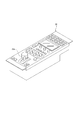
- FIG. 2 is a perspective view showing an example of an external configuration of the remote controller 30.
- the remote controller 30 is formed with controls such as a plurality of buttons and knobs.
- the remote controller 30 is formed with an adjustment operator 30a for adjusting the brightness of the captured image.
- the adjustment operator 30a is, for example, a lever-type operator, and it is possible to change the indicated value of the brightness of the captured image by the operation of rotating the adjustment operator 30a. Specifically, at the position where the adjustment operator 30a reaches one end, the indicated value indicates the darkest brightness (the maximum value in the case of the F value described later), and the adjustment operator 30a is the other end.
- the indicated value indicates the brightest brightness (the minimum value in the case of the F value described later) at the position where the portion is reached. Further, the indicated value changes monotonically from one end to the other end (for example, linearly).
- the adjustment operator 30a is not limited to a lever type operator, but may be an operator of another type such as a rotary type operator or a slide type operator.
- the remote controller 30 uses the target value of the F value according to the operating state of the adjustment operator 30a, specifically, the rotation angle of the adjustment operator 30a (hereinafter referred to as “target value F_target”). Is output to the CCU 20 as an indicated value for brightness.
- the F value here may be a value indicating brightness equivalent to the F value according to the change in the effective aperture of the lens due to the drive of the iris, and does not necessarily correspond to the change in the effective aperture of the lens due to the drive of the iris. It does not have to be the value of the F value itself.
- the CCU 20 passes the target value F_target input from the remote controller 30 to the control unit 7 in the image pickup apparatus 1.
- the remote controller 30 outputs the target value F_target, but the CCU 20 is based on the operation input signal from the remote controller 30 (for example, a signal indicating a value corresponding to the rotation angle of the adjustment operator 30a). It is also possible to adopt a configuration in which the target value F_target is generated and passed to the control unit 7.
- control unit 7 adjusts the brightness of the captured image by outputting the F value to the iris drive unit 11 and the gain G to the amplification unit 4 based on the target value F_target input from the CCU 20.
- the specific processing executed by the control unit 7 for adjusting the brightness of the captured image will be described in detail below.
- the image pickup apparatus 1 performs correction processing (processing of the first correction processing unit 3 and the second correction processing unit 5) and development processing (processing of the development processing unit 6), but a part thereof is omitted. Or the order may be changed.
- Brightness adjustment method as an embodiment> A specific process performed by the control unit 7 for adjusting the brightness of the captured image will be described.
- the brightness of the captured image may be simply abbreviated as “brightness”.
- “optical brightness adjustment” which is the brightness adjustment by the iris, according to the change of the indicated value (target value F_target in this example) that indicates the brightness, and according to the indicated value. It switches to “electronic brightness adjustment”, which is brightness adjustment by giving a gain to the captured image.
- the target value F_target of the F value is input to the control unit 7 as the brightness instruction value in response to the operation of the adjustment operator 30a in the remote controller 30.
- the threshold value F_th with respect to the target value F_target of the F value as the indicated value of such brightness is defined, and the control unit 7 sets the optical brightness based on the comparison result between the target value F_target and the threshold value F_th. Switch between threshold adjustment and electronic brightness adjustment.
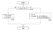
- FIG. 3 and 4 are diagrams for explaining an example of switching between optical brightness adjustment and electronic brightness adjustment
- FIG. 3 is a conceptual diagram of the switching example
- FIG. 4 is for the switching.
- An example of processing executed by the control unit 7 is shown.
- the minimum value of the F value is, for example, F1.8
- the threshold value F_th is set to F4.0 (see FIG. 3).
- the control unit 7 determines whether or not the target value F_target is equal to or less than the threshold F_th (step S101 in FIG. 4), and if the target value F_target is not equal to or less than the threshold F_th, the control unit 7 targets the F value instructed to the iris drive unit 11.
- the value F_target is set, and the target value G_target of the gain G instructed to the amplification unit 4 is set to “1” (step S102).
- the target value F_target is not equal to or less than the threshold value F_th in this way, the target value G_target is set to "1" and the brightness is not adjusted by the gain G, while the F value is set to the target value F_target.
- Brightness is adjusted by the iris (see FIG. 3). That is, when the target value F_target is larger than the threshold value F_th, the electronic brightness adjustment is not performed and the optical brightness adjustment is performed.
- the control unit 7 sets the F value instructed to the iris drive unit 11 as the threshold value F_th, and sets the target value G_target of the gain G as the brightness at the target value F_target and the threshold value F_th.
- a value corresponding to the difference from the brightness of, specifically, a value of (brightness at the target value F_target) / (brightness at the threshold value F_th) (step S103).
- the F value is set to the threshold F_th and the brightness is not adjusted by the iris, while the target value G_target depends on the size of the target value F_target of the F value. Therefore, the brightness is adjusted by the gain G (see FIG. 3).
- the optical brightness adjustment is performed up to a predetermined F value. Therefore, it is possible to suppress the decrease in resolving power that occurs when only the optical brightness is adjusted.
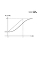
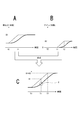
- FIG. 5 schematically shows the change characteristic of brightness (thick solid line in the figure) with respect to the target value F_target (thick dotted line in the figure) when the iris is used.
- the change characteristic when the target value F_target is changed at a constant speed from the time point T0 to the time point T1 to a value corresponding to the brightness Bx is shown.
- the change characteristic of the brightness when the iris is used is a characteristic with a delay with respect to the change of the target value F_target.
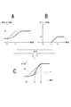
- FIG. 6 is an explanatory diagram of this point.
- the brightness is changed from the time point T0 to the time point T1 by optical brightness adjustment to B1
- the time point T1 It is assumed that the logarithm of the gain is changed from 0 to B2 by electronic brightness adjustment from the time point T2 to the time point T2.
- the change characteristic of the brightness from the time point T0 to the time point T2 corresponds to the combination of the change characteristics of FIGS. 6A and 6B, and has the characteristics shown in FIG. 6C.
- the change speed of the brightness changes abruptly due to the difference in the change characteristics of FIGS. 6A and 6B. There will be a part to do.
- FIG. 7 is a functional block diagram showing the function of the control unit 7 for adjusting the brightness.
- the control unit 7 has a function as a switching unit 7a and a function as a filter unit 7b. ..
- the switching unit 7a performs the process shown in FIG. 4 to switch between the optical brightness adjustment and the electronic brightness adjustment.
- the filter unit 7b is a digital filter realized by software processing, and functions as a delay filter that delays the target value G_target of the gain G input from the switching unit 7a.
- the target value G_target delayed by the filter unit 7b is output to the amplification unit 4 as a gain G.
- the second example is an example of limiting the rate of change.
- the actual iris has an upper limit on the rate of change. Therefore, even in the delay characteristic of the filter unit 7b, the change speed is set to an upper limit so as to be closer to the characteristic of the iris.
- the value obtained by multiplying the difference between the target value G_target and the current gain G value G (t) by the proportional coefficient p is the current gain G value G ( The method of adding to t) is followed, but in the second example, the value to be added to G (t) (the following “ ⁇ G (t)” is limited based on the upper limit value ⁇ G_max of the amount of change in the gain G.
- > ⁇ G_max ⁇ G'(t) ⁇ G_max ⁇ ⁇ G (t) /
- the third example considers the inertia acting on the iris. Since the actual iris is driven by something with mass, it has inertia and almost no speed at the beginning of movement. Therefore, by setting the delay characteristic to imitate the inertia acting on the iris, the characteristic of the iris can be made closer. Specifically, the current amount of change in gain G is Gs (t), and the amount of change in gain G at the current next time is Gs (t + 1).
- FIG. 8 is a diagram for explaining the action of delaying the gain G.
- the gain G is changed with respect to the change in the target value F_target.
- the change characteristic of the gain G with respect to the change of the target value F_target that is, the change characteristic of the brightness in the electronic brightness adjustment is linear regardless of which of the first to third examples described above is adopted. It is not a curvilinear characteristic.
- the change in the gain G is within the period in which the gain G is changed in the optical brightness adjustment (in the example in the figure, the period after the time point T1).
- a response period in which the gain G hardly changes with respect to the change in the target value F_target can be obtained in the vicinity of the time point T1 which is the timing of switching to the electronic brightness adjustment. ..
- the brightness change characteristic due to the brightness adjustment in this example is a combination of the brightness change characteristic due to the optical brightness adjustment shown in FIG. 8A and the brightness change characteristic due to the electronic brightness adjustment shown in FIG. 8B.
- the brightness change characteristic due to the electronic brightness adjustment becomes the brightness due to the optical brightness adjustment.
- the change in brightness can be smoothed (see the part represented by "X" in FIG. 8C).
- the filter unit 7b functions as a filter having a delay time, it also serves as a low-pass filter. Since the filter unit 7b also functions as a low-pass filter in this way, in this example, even if the adjustment operator 30a is operated in small steps, it is possible to prevent the value of the gain G from changing in small steps. That is, it is possible to prevent the brightness from changing in small steps. Even if the user wants to change the target value F_target at a constant speed, the speed may change due to, for example, hand tremor. In such a case, by suppressing the response to the small operation, the brightness can be adjusted according to the intention of the user, and the operability related to the brightness adjustment can be improved.
- the control unit 7 in this example has the optical brightness adjustment and the electronic brightness adjustment as described above as the brightness adjustment mode according to the target value F_target instructed by the operation of the adjustment operator 30a. It is possible to switch between a switching mode in which switching control is performed and a non-switching mode in which optical brightness adjustment is performed without switching control.
- the non-switching mode can be said to be a mode in which the F value is changed according to the change in the target value F_target even if the target value F_target is equal to or less than the threshold value F_th.
- control unit 7 executes the switching between the switching mode and the non-switching mode as described above based on the operation of the remote controller 30.
- the remote controller 30 is provided with an operator such as a button for instructing switching between the switching mode and the non-switching mode, and the remote controller 30 provides corresponding operation input information according to the operation of the operator. Is output to the CCU 20. This operation input information is passed to the control unit 7 via the CCU 20.
- providing the non-switching mode as described above to enable the F value to be lowered to the minimum value according to the operation of the adjustment operator 30a has the following advantages.
- One is that the efficiency of the adjustment work in the flange back adjustment (adjustment of the distance from the mounting surface of the lens device 10 to the image plane) can be improved.
- the flange back adjustment is performed while observing the blurring that occurs in the captured image, but if the F value cannot be reduced during the adjustment, the blurring is unlikely to occur, and the flange back adjustment becomes difficult. Therefore, by switching to the non-switching mode so that the F value can be set smaller than the threshold value F_th, blurring of the captured image is likely to occur, and the efficiency of the adjustment work can be improved.
- Another advantage is that it is possible to respond to drawing intentions such as wanting to generate background blur. Some users of the imaging system want to create fantastic image content with a blurred background, and such a request can be met.
- the mode switching operation between the switching mode and the non-switching mode is not limited to the operation of the remote controller 30, but can also be an operation for the image pickup apparatus 1.
- the mode switching operation is the operation of the remote controller 30
- the photographer does not have to bear the operation burden of the mode switching.
- the flange back adjustment described above is performed by the photographer, it is not desirable to impose an extra operational burden on the photographer during the flange back adjustment in terms of improving the efficiency of the adjustment work.
- the mode switching operation can be performed by a person other than the cameraman such as a video engineer, and the operation burden of the cameraman at the time of flange back adjustment can be reduced, and the adjustment work can be performed. Efficiency can be improved.
- the threshold value F_th used for switching between the optical brightness adjustment and the electronic brightness adjustment shall be variable according to, for example, the operation input and the type of the lens device 10. Can be done. It is conceivable that the F value at which the resolving power begins to decrease may change depending on the type and individual of the lens device 10. In such a case, by making the threshold value F_th variable according to the type of the lens device 10, the effect of suppressing the decrease in the resolving power is achieved. Can be enhanced.
- the filter characteristic of the filter unit 7b that is, the delay characteristic of the gain G can be made variable.
- this delay characteristic is variable according to the characteristics of the iris in the lens device 10.
- FIG. 9 is a diagram for explaining a configuration of an imaging system as a first modification.
- the same parts as those already explained will be designated by the same reference numerals and the description thereof will be omitted.
- the CCU 20 and the remote controller 30 are not shown.
- the lens device 10A that stores information representing the filter characteristics of the filter unit 7b is used.
- the lens device 10A is different from the lens device 10 in that it includes a storage unit 12 as a non-volatile memory.
- the storage unit 12 stores filter characteristic information 12a representing the filter characteristics of the filter unit 7b corresponding to the characteristics of the iris of the lens device 10A.
- an imaging device 1A is provided instead of the imaging device 1.
- the image pickup device 1A is different from the image pickup device 1 in that the control unit 7A is provided instead of the control unit 7.
- the control unit 7A acquires the filter characteristic information 12a from the storage unit 12 of the lens device 10A mounted on the image pickup device 1A, and in the electronic brightness adjustment, the delay characteristic (that is, the filter) according to the acquired filter characteristic information 12a.
- the target value G_target is delayed by the filter characteristic of part 7b).
- the filter characteristic information 12a when an FIR (Finite Impulse Response) filter is used as the filter unit 7b, it is conceivable to use information such as a tap coefficient and the number of taps.
- FIR Finite Impulse Response
- the example of changing the delay characteristic of the gain G according to the characteristic of the iris is not limited to the example of storing the filter characteristic information 12a in the lens device 10A as described above.
- individual identification information for each lens device 10A for example, information such as the model number and serial number of the lens device 10A
- the control unit 7A corresponds to the individual identification information acquired from the lens device 10A.
- the table information indicating the correspondence between the individual identification information and the delay characteristic is stored in a predetermined storage means (for example, a memory included in the control unit 7A), and the control unit 7A stores the table information. Based on the acquired individual identification information, the target value G_target is delayed by the delay characteristic specified from the table information.
- the delay characteristic of the gain G can be changed for each lens device 10A to be mounted, but instead of this, for example, a change in the characteristic of the iris over time (for example, due to aged deterioration of the mechanical portion). It is also conceivable that the delay characteristic of the gain G can be changed in response to the accompanying characteristic change).
- the gain delay characteristics to be changeable, the brightness change characteristics by electronic brightness adjustment can be optically adjusted in response to changes in the iris characteristics for some reason. It is possible to change the characteristics according to the characteristics of the change in brightness due to. That is, it is possible to alleviate the discomfort of the user when the brightness adjustment is switched and to suppress the deterioration of the operability related to the brightness adjustment in response to the case where the characteristics of the iris change for some reason.
- the gain G is filtered so as to have the same characteristic as the ideal response characteristic, and for an iris that does not have the ideal response characteristic,
- the total characteristics of "iris + filter” can be made the same as the ideal iris response characteristics. Therefore, the ideal response characteristics can be realized in both the optical brightness adjustment and the electronic brightness adjustment, so that the user's discomfort related to the brightness adjustment can be alleviated and the deterioration of the operability related to the brightness adjustment can be suppressed. Can be planned.
- the filter processing for the delay of the gain G is performed as the software processing of the control unit 7
- the filter unit 8 that performs the filter processing is used. It can also be provided as an external circuit.
- the control unit 7C is different from the control unit 7 in that the control unit 7C includes the switching unit 7a shown in FIG. 7 as a functional unit related to the brightness adjustment, and the filter unit 7b is omitted.
- the filter unit 8 performs a filter process of delaying the change of the target value G_target output from the control unit 7 (switching unit 7a) with respect to the change of the target value F_target of the F value, and the gain G obtained by the filter process is performed. Is output to the amplification unit 4.
- FIG. 12 shows a configuration example of the imaging system in that case.
- the imaging device 1D is provided in place of the imaging device 1
- the CCU 20D is provided in place of the CCU 20.
- the CCU 20D includes a control unit 20a configured to include, for example, a microcomputer equipped with a CPU, ROM, RAM, and the like.
- the control unit 20a controls the operation of the image pickup apparatus 1D based on, for example, operation input information from the remote controller 30.
- the control unit 20a of the CCU 20D is provided with the functional unit related to the brightness adjustment shown in FIG. Specifically, it is a switching unit 7a and a filter unit 7b.
- the F value output from the switching unit 7a of the control unit 20a and the gain G output from the filter unit 7b of the control unit 20a pass through the control unit 7D included in the image pickup apparatus 1D, respectively, and the iris drive unit. 11. Instructed by the amplification unit 4.
- the control unit 7D is different from the control unit 7 in that the switching unit 7a and the filter unit 7b are omitted.
- the signal processing device (imaging device 1 or CCU20D) of the embodiment has optical brightness, which is brightness adjustment by an iris in response to a change in an instruction value indicating the brightness of an image captured by the imaging device.
- the switching unit (7a) that switches between the adjustment and the electronic brightness adjustment, which is the brightness adjustment by giving the captured image a gain according to the indicated value, and the indicated value in the electronic brightness adjustment. It is provided with a first delay unit (filter units 7b, 8) that delays the change in gain with respect to the change. By delaying the change in gain with respect to the change in the indicated value in the electronic brightness adjustment, the indicated value changes below the threshold value and the brightness adjustment is switched from the optical brightness adjustment to the electronic brightness adjustment.
- the indicated value is set as the target value (F_target) of the F value.
- the switching unit performs switching control based on the comparison result between the indicated value and the threshold value.
- the optical brightness adjustment is performed up to a predetermined F value. Therefore, the effect of suppressing the decrease in resolving power can be enhanced.
- the indicated value is set as the target value of the F value
- the switching unit performs optical brightness adjustment on the side where the target value of the F value is larger than the threshold value, and F.
- Switching control is performed so that the electronic brightness is adjusted on the side where the target value of the value is small. That is, the optical brightness is adjusted in the region where the F value is large and the resolving power is good, and the electronic brightness is adjusted instead of the optical brightness adjustment in the region where the F value is small and the resolving power tends to decrease. To. Therefore, it is possible to suppress a decrease in resolving power due to brightness adjustment.
- the first delay unit changes the gain change rate within the period in which the gain is changed in the electronic brightness adjustment (the period after the time point T1 in FIG. 8B). There is.
- the first delay unit changes the gain change rate within the period in which the gain is changed in the electronic brightness adjustment (the period after the time point T1 in FIG. 8B).
- the first delay unit suppresses the change speed of the gain in the electronic brightness adjustment to a predetermined speed or less. Due to the characteristics of the iris, there is an upper limit to the brightness change speed in optical brightness adjustment. Therefore, by suppressing the change speed of the gain to a predetermined speed or less in the electronic brightness adjustment, the brightness change characteristic by the electronic brightness adjustment can be brought close to the brightness change characteristic by the optical brightness adjustment. It is possible to enhance the effect of alleviating the discomfort of the user and the observer of the output image related to the change and the effect of suppressing the deterioration of operability related to the brightness adjustment.
- the first delay unit delays the gain by the delay characteristic imitating the inertia in the electronic brightness adjustment. This makes it possible to change the brightness change characteristic by electronic brightness adjustment into a change characteristic that takes into account the inertia acting on the iris. Therefore, the brightness change characteristic by the electronic brightness adjustment can be brought close to the brightness change characteristic by the optical brightness adjustment, and the effect of alleviating the discomfort of the user and the observer of the output image related to the brightness change and the brightness It is possible to enhance the effect of suppressing deterioration of operability related to the adjustment.
- the switching unit has a switching mode in which switching control between optical brightness adjustment and electronic brightness adjustment is performed according to a change in the indicated value, and a change in the indicated value. It is possible to switch to a non-switching mode in which optical brightness adjustment is performed without switching control. This makes it possible to reduce the F value to the minimum value. Therefore, the efficiency of the flange back adjustment work can be improved. In addition, it is possible to respond to the drawing intention such as wanting to generate background blur.
- the switching unit switches between the switching mode and the non-switching mode based on the operation. As a result, it is possible to switch between the switching mode and the non-switching mode based on the intention of the user. Therefore, it is possible to improve the convenience of the user.
- the switching unit switches between the switching mode and the non-switching mode based on the operation of the remote controller (30).
- the photographer does not have to bear the burden of switching the switching mode / non-switching mode.
- the flange back adjustment is performed by the photographer, it is not desirable to impose an extra operational burden on the photographer when adjusting the flange back in terms of improving the efficiency of the adjustment work.
- the mode switching is performed based on the operation of the remote controller as described above, the mode switching operation can be performed by a person other than the cameraman such as a video engineer, and the operation load of the cameraman at the time of flange back adjustment can be reduced. Therefore, the efficiency of adjustment work can be improved.
- the first delay unit can change the delay characteristic of the gain in the electronic brightness adjustment.
- the image pickup device is an interchangeable lens type image pickup device
- the first delay unit changes the gain by the delay characteristic based on the information acquired from the lens device mounted on the image pickup device. I'm delaying.
- the signal processing apparatus of the embodiment includes a second delay unit (filter unit 7c) that delays the change of the F value with respect to the change of the indicated value in the optical brightness adjustment.
- filter unit 7c filters the change characteristic of the F value with respect to the change of the indicated value in the optical brightness adjustment. This makes it possible to make the change characteristic of the F value with respect to the change of the indicated value a desired characteristic. Therefore, it is possible to alleviate the discomfort of the user related to the brightness adjustment and the observer of the output image, and to suppress the deterioration of the operability related to the brightness adjustment.
- the imaging device (1,1A, 1C, 1D) of the embodiment is an imaging element (2) that receives incident light via an iris to obtain an captured image, and an instruction for instructing the brightness of the captured image.
- It is provided with a unit (7a) and a first delay unit (filter units 7b, 8) that delays a change in gain with respect to a change in an indicated value in electronic brightness adjustment.
- the image pickup apparatus as such an embodiment also has the same functions and effects as the signal processing apparatus as the above-described embodiment.
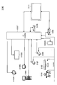
- FIG. 13 is a diagram schematically showing the overall configuration of the operating room system 5100 to which the technique according to the present disclosure can be applied.
- the operating room system 5100 is configured by connecting a group of devices installed in the operating room in a coordinated manner via an audiovisual controller (AV Controller) 5107 and an operating room control device 5109.
- AV Controller audiovisual controller
- FIG. 13 As an example, various device groups 5101 for endoscopic surgery, a ceiling camera 5187 provided on the ceiling of the operating room to capture the operator's hand, and an operating room provided on the ceiling of the operating room.
- An operating room camera 5189 that captures the entire state, a plurality of display devices 5103A to 5103D, a recorder 5105, a patient bed 5183, and an illumination 5191 are illustrated.
- the device group 5101 belongs to the endoscopic surgery system 5113 described later, and includes an endoscope, a display device that displays an image captured by the endoscope, and the like.
- Each device belonging to the endoscopic surgery system 5113 is also referred to as a medical device.
- the display devices 5103A to 5103D, the recorder 5105, the patient bed 5183, and the lighting 5191 are devices provided in the operating room, for example, separately from the endoscopic surgery system 5113.
- Each of these devices that does not belong to the endoscopic surgery system 5113 is also referred to as a non-medical device.
- the audiovisual controller 5107 and / or the operating room controller 5109 controls the operations of these medical devices and non-medical devices in cooperation with each other.
- the audiovisual controller 5107 comprehensively controls processing related to image display in medical devices and non-medical devices.
- the device group 5101, the sealing camera 5187, and the operating room camera 5189 have a function of transmitting information to be displayed during the operation (hereinafter, also referred to as display information).
- It can be a device (hereinafter, also referred to as a source device).
- the display devices 5103A to 5103D may be devices for outputting display information (hereinafter, also referred to as output destination devices).
- the recorder 5105 may be a device corresponding to both the source device and the output destination device.
- the audiovisual controller 5107 controls the operation of the source device and the output destination device, acquires display information from the source device, and transmits the display information to the output destination device for display or recording.
- the displayed information includes various images captured during the operation, various information related to the operation (for example, physical information of the patient, past test results, information on the surgical procedure, etc.).
- the audiovisual controller 5107 can be transmitted from the device group 5101 as display information about an image of the surgical site in the body cavity of the patient captured by the endoscope.
- the sealing camera 5187 may transmit information about the image at the operator's hand captured by the sealing camera 5187 as display information.
- the operating room camera 5189 may transmit as display information information about an image showing the state of the entire operating room captured by the operating room camera 5189.
- the audiovisual controller 5107 also acquires information about an image captured by the other device from the other device as display information. You may.
- the recorder 5105 records information about these images captured in the past by the audiovisual controller 5107.
- the audiovisual controller 5107 can acquire information about the previously captured image from the recorder 5105 as display information.
- various information about the operation may be recorded in advance in the recorder 5105.
- the audiovisual controller 5107 causes at least one of the display devices 5103A to 5103D, which is the output destination device, to display the acquired display information (that is, an image taken during the operation and various information related to the operation).
- the display device 5103A is a display device suspended from the ceiling of the operating room
- the display device 5103B is a display device installed on the wall surface of the operating room
- the display device 5103C is in the operating room. It is a display device installed on a desk
- the display device 5103D is a mobile device having a display function (for example, a tablet PC (Personal Computer)).
- the operating room system 5100 may include a device outside the operating room.
- the device outside the operating room may be, for example, a server connected to a network constructed inside or outside the hospital, a PC used by medical staff, a projector installed in a conference room of the hospital, or the like.
- the audiovisual controller 5107 can also display display information on a display device of another hospital via a video conferencing system or the like for telemedicine.
- the operating room control device 5109 comprehensively controls processing other than processing related to image display in non-medical equipment.
- the operating room control device 5109 controls the drive of the patient bed 5183, the sealing camera 5187, the operating room camera 5189, and the lighting 5191.
- the operating room system 5100 is provided with a centralized operation panel 5111, and the user gives an instruction regarding image display to the audiovisual controller 5107 or gives an instruction to the operating room control device 5109 via the centralized operation panel 5111. On the other hand, instructions on the operation of non-medical devices can be given.
- the centralized operation panel 5111 is configured by providing a touch panel on the display surface of the display device.
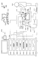
- FIG. 14 is a diagram showing a display example of an operation screen on the centralized operation panel 5111.
- FIG. 14 shows, as an example, an operation screen corresponding to a case where the operating room system 5100 is provided with two display devices as output destination devices.
- the operation screen 5193 is provided with a source selection area 5195, a preview area 5197, and a control area 5201.
- the source device provided in the operating room system 5100 and the thumbnail screen showing the display information possessed by the source device are linked and displayed.
- the user can select the display information to be displayed on the display device from any of the source devices displayed in the source selection area 5195.
- a preview of the screen displayed on the two display devices which are the output destination devices, is displayed.
- four images are displayed in PinP on one display device.
- the four images correspond to the display information transmitted from the source device selected in the source selection area 5195.
- one is displayed relatively large as the main image and the remaining three are displayed relatively small as the sub-image.
- the user can switch the main image and the sub image by appropriately selecting the area in which the four images are displayed.
- a status display area 5199 is provided below the area where the four images are displayed, and the status related to the surgery (for example, the elapsed time of the surgery, the physical information of the patient, etc.) is appropriately displayed in the area. obtain.
- the control area 5201 includes a source operation area 5203 in which GUI (Graphical User Interface) components for operating the source device are displayed, and GUI components for operating the output destination device. Is provided with an output destination operation area 5205 and.
- GUI Graphic User Interface
- the source operation area 5203 is provided with GUI components for performing various operations (pan, tilt, zoom) on the camera in the source device having an imaging function. The user can operate the operation of the camera in the source device by appropriately selecting these GUI components.
- the source device selected in the source selection area 5195 is a recorder (that is, in the preview area 5197, an image recorded in the past is displayed on the recorder.
- the source operation area 5203 may be provided with a GUI component for performing operations such as playing, stopping, rewinding, and fast-forwarding the image.
- GUI parts for performing various operations for the display on the display device which is the output destination device are provided. It is provided. The user can operate the display on the display device by appropriately selecting these GUI components.
- the operation screen displayed on the centralized operation panel 5111 is not limited to the illustrated example, and the user can use the audiovisual controller 5107 and the operating room control device 5109 provided in the operating room system 5100 via the centralized operation panel 5111. Operational inputs to each device that can be controlled may be possible.
- FIG. 15 is a diagram showing an example of an operation in which the operating room system described above is applied.
- the ceiling camera 5187 and the operating room camera 5189 are provided on the ceiling of the operating room, and can photograph the hands of the surgeon (doctor) 5181 who treats the affected part of the patient 5185 on the patient bed 5183 and the entire operating room. Is.
- the sealing camera 5187 and the operating field camera 5189 may be provided with a magnification adjusting function, a focal length adjusting function, a shooting direction adjusting function, and the like.
- the illumination 5191 is provided on the ceiling of the operating room and illuminates at least the hands of the surgeon 5181.
- the illumination 5191 may be capable of appropriately adjusting the amount of irradiation light, the wavelength (color) of the irradiation light, the irradiation direction of the light, and the like.
- the endoscopic surgery system 5113, patient bed 5183, sealing camera 5187, operating room camera 5189 and lighting 5191 are via an audiovisual controller 5107 and an operating room control device 5109 (not shown in FIG. 15), as shown in FIG. Are connected so that they can cooperate with each other.
- a centralized operation panel 5111 is provided in the operating room, and as described above, the user can appropriately operate these devices existing in the operating room through the centralized operation panel 5111.
- the endoscopic surgery system 5113 includes an endoscope 5115, other surgical tools 5131, a support arm device 5141 that supports the endoscope 5115, and various devices for endoscopic surgery. It is composed of a cart 5151 on which the
- trocca 5139a-5139d In endoscopic surgery, instead of cutting the abdominal wall to open the abdomen, multiple tubular laparotomy instruments called trocca 5139a-5139d are punctured into the abdominal wall. Then, the lens barrel 5117 of the endoscope 5115 and other surgical tools 5131 are inserted into the body cavity of the patient 5185 from the troccers 5139a to 5139d.
- a pneumoperitoneum tube 5133, an energy treatment tool 5135, and forceps 5137 are inserted into the body cavity of patient 5185.
- the energy treatment tool 5135 is a treatment tool that cuts and peels tissue, seals a blood vessel, or the like by using a high-frequency current or ultrasonic vibration.
- the surgical tool 5131 shown is only an example, and as the surgical tool 5131, various surgical tools generally used in endoscopic surgery such as a sword and a retractor may be used.
- the image of the surgical site in the body cavity of the patient 5185 taken by the endoscope 5115 is displayed on the display device 5155. While viewing the image of the surgical site displayed on the display device 5155 in real time, the surgeon 5181 uses the energy treatment tool 5135 and forceps 5137 to perform a procedure such as excising the affected area. Although not shown, the pneumoperitoneum tube 5133, the energy treatment tool 5135, and the forceps 5137 are supported by the surgeon 5181 or an assistant during the operation.
- the support arm device 5141 includes an arm portion 5145 extending from the base portion 5143.
- the arm portion 5145 is composed of joint portions 5147a, 5147b, 5147c, and links 5149a, 5149b, and is driven by control from the arm control device 5159.
- the endoscope 5115 is supported by the arm portion 5145, and its position and posture are controlled. As a result, the stable position of the endoscope 5115 can be fixed.
- the endoscope 5115 is composed of a lens barrel 5117 in which a region having a predetermined length from the tip is inserted into the body cavity of the patient 5185, and a camera head 5119 connected to the base end of the lens barrel 5117.
- the endoscope 5115 configured as a so-called rigid mirror having a rigid barrel 5117 is illustrated, but the endoscope 5115 is configured as a so-called flexible mirror having a flexible barrel 5117. May be good.
- the tip of the lens barrel 5117 is provided with an opening in which the objective lens is fitted.
- a light source device 5157 is connected to the endoscope 5115, and the light generated by the light source device 5157 is guided to the tip of the lens barrel by a light guide extending inside the lens barrel 5117, and is an objective. It is irradiated toward the observation target in the body cavity of the patient 5185 through the lens.
- the endoscope 5115 may be a direct endoscope, a perspective mirror, or a side endoscope.
- An optical system and an image sensor are provided inside the camera head 5119, and the reflected light (observation light) from the observation target is focused on the image sensor by the optical system.
- the observation light is photoelectrically converted by the image sensor, and an electric signal corresponding to the observation light, that is, an image signal corresponding to the observation image is generated.
- the image signal is transmitted as RAW data to the camera control unit (CCU: Camera Control Unit) 5153.
- the camera head 5119 is equipped with a function of adjusting the magnification and the focal length by appropriately driving the optical system.
- the camera head 5119 may be provided with a plurality of image pickup elements in order to support stereoscopic viewing (3D display) and the like.
- a plurality of relay optical systems are provided inside the lens barrel 5117 in order to guide the observation light to each of the plurality of image pickup elements.
- the CCU 5153 is composed of a CPU (Central Processing Unit), a GPU (Graphics Processing Unit), and the like, and comprehensively controls the operations of the endoscope 5115 and the display device 5155. Specifically, the CCU 5153 performs various image processing for displaying an image based on the image signal, such as development processing (demosaic processing), on the image signal received from the camera head 5119. The CCU 5153 provides the display device 5155 with the image signal subjected to the image processing. Further, the audiovisual controller 5107 shown in FIG. 13 is connected to the CCU 5153. CCU5153 also provides the image processed image signal to the audiovisual controller 5107.
- the CCU 5153 transmits a control signal to the camera head 5119 and controls the driving thereof.
- the control signal may include information about imaging conditions such as magnification and focal length.
- the information regarding the imaging condition may be input via the input device 5161 or may be input via the centralized operation panel 5111 described above.
- the display device 5155 displays an image based on the image signal processed by the CCU 5153 under the control of the CCU 5153.
- the endoscope 5115 is compatible with high-resolution shooting such as 4K (3840 horizontal pixels x 2160 vertical pixels) or 8K (7680 horizontal pixels x 4320 vertical pixels), and / or 3D display.
- the display device 5155 a device capable of displaying a high resolution and / or a device capable of displaying in 3D can be used corresponding to each of the above.
- a display device 5155 having a size of 55 inches or more is used for high-resolution shooting such as 4K or 8K, a further immersive feeling can be obtained.
- a plurality of display devices 5155 having different resolutions and sizes may be provided depending on the application.
- the light source device 5157 is composed of, for example, a light source such as an LED (light LED diode), and supplies the irradiation light for photographing the surgical site to the endoscope 5115.
- a light source such as an LED (light LED diode)
- the arm control device 5159 is composed of a processor such as a CPU, and operates according to a predetermined program to control the drive of the arm portion 5145 of the support arm device 5141 according to a predetermined control method.
- the input device 5161 is an input interface for the endoscopic surgery system 5113.
- the user can input various information and input instructions to the endoscopic surgery system 5113 via the input device 5161.
- the user inputs various information related to the surgery, such as physical information of the patient and information about the surgical procedure, via the input device 5161.
- the user gives an instruction to drive the arm portion 5145 via the input device 5161 and an instruction to change the imaging conditions (type of irradiation light, magnification, focal length, etc.) by the endoscope 5115.
- Input an instruction to drive the energy treatment tool 5135, and the like.
- the type of the input device 5161 is not limited, and the input device 5161 may be various known input devices.
- the input device 5161 for example, a mouse, a keyboard, a touch panel, a switch, a foot switch 5171 and / or a lever and the like can be applied.
- the touch panel may be provided on the display surface of the display device 5155.
- the input device 5161 is a device worn by the user, such as a glasses-type wearable device or an HMD (Head Mounted Display), and various inputs are made according to the user's gesture and line of sight detected by these devices. Is done. Further, the input device 5161 includes a camera capable of detecting the movement of the user, and various inputs are performed according to the gesture and the line of sight of the user detected from the image captured by the camera. Further, the input device 5161 includes a microphone capable of picking up the user's voice, and various inputs are performed by voice through the microphone.
- a glasses-type wearable device or an HMD Head Mounted Display
- the input device 5161 is configured to be able to input various information in a non-contact manner, so that a user belonging to a clean area (for example, an operator 5181) can operate a device belonging to a dirty area in a non-contact manner. Is possible. In addition, since the user can operate the device without taking his / her hand off the surgical tool he / she has, the convenience of the user is improved.
- the treatment tool control device 5163 controls the drive of the energy treatment tool 5135 for ablation of tissue, incision, sealing of blood vessels, and the like.
- the pneumoperitoneum device 5165 gas in the body cavity of the patient 5185 via the pneumoperitoneum tube 5133 for the purpose of securing the field of view by the endoscope 5115 and securing the work space of the operator.
- Recorder 5167 is a device capable of recording various information related to surgery.
- the printer 5169 is a device capable of printing various information related to surgery in various formats such as text, images, and graphs.
- the support arm device 5141 includes a base portion 5143 that is a base, and an arm portion 5145 that extends from the base portion 5143.
- the arm portion 5145 is composed of a plurality of joint portions 5147a, 5147b, 5147c and a plurality of links 5149a, 5149b connected by the joint portions 5147b, but in FIG. 15, for simplicity.
- the configuration of the arm portion 5145 is shown in a simplified manner. Actually, the shapes, numbers and arrangements of the joint portions 5147a to 5147c and the links 5149a and 5149b, and the direction of the rotation axis of the joint portions 5147a to 5147c are appropriately set so that the arm portion 5145 has a desired degree of freedom. obtain.
- the arm portion 5145 can be preferably configured to have at least 6 degrees of freedom.
- the endoscope 5115 can be freely moved within the movable range of the arm portion 5145, so that the lens barrel 5117 of the endoscope 5115 can be inserted into the body cavity of the patient 5185 from a desired direction. It will be possible.
- Actuators are provided in the joint portions 5147a to 5147c, and the joint portions 5147a to 5147c are configured to be rotatable around a predetermined rotation axis by driving the actuator.
- the arm control device 5159 By controlling the drive of the actuator by the arm control device 5159, the rotation angles of the joint portions 5147a to 5147c are controlled, and the drive of the arm portion 5145 is controlled. Thereby, control of the position and orientation of the endoscope 5115 can be realized.
- the arm control device 5159 can control the drive of the arm unit 5145 by various known control methods such as force control or position control.
- the arm control device 5159 appropriately controls the drive of the arm portion 5145 in response to the operation input.
- the position and orientation of the endoscope 5115 may be controlled.
- the endoscope 5115 at the tip of the arm portion 5145 can be moved from an arbitrary position to an arbitrary position, and then fixedly supported at the moved position.
- the arm portion 5145 may be operated by a so-called master slave method. In this case, the arm portion 5145 can be remotely controlled by the user via an input device 5161 installed at a location away from the operating room.
- the arm control device 5159 When force control is applied, the arm control device 5159 receives an external force from the user and moves the actuators of the joint portions 5147a to 5147c so that the arm portion 5145 moves smoothly according to the external force. So-called power assist control for driving may be performed. As a result, when the user moves the arm portion 5145 while directly touching the arm portion 5145, the arm portion 5145 can be moved with a relatively light force. Therefore, the endoscope 5115 can be moved more intuitively and with a simpler operation, and the convenience of the user can be improved.
- the endoscope 5115 was supported by a doctor called a scopist.
- the position of the endoscope 5115 can be fixed more reliably without human intervention, so that an image of the surgical site can be stably obtained. , It becomes possible to perform surgery smoothly.
- the arm control device 5159 does not necessarily have to be provided on the cart 5151. Further, the arm control device 5159 does not necessarily have to be one device. For example, the arm control device 5159 may be provided at each joint portion 5147a to 5147c of the arm portion 5145 of the support arm device 5141, and a plurality of arm control devices 5159 cooperate with each other to drive the arm portion 5145. Control may be realized.
- the light source device 5157 supplies the endoscope 5115 with the irradiation light for photographing the surgical site.
- the light source device 5157 is composed of, for example, an LED, a laser light source, or a white light source composed of a combination thereof.
- a white light source is configured by combining RGB laser light sources, the output intensity and output timing of each color (each wavelength) can be controlled with high accuracy. Therefore, the light source device 5157 white balances the captured image. Can be adjusted.
- the laser light from each of the RGB laser light sources is irradiated to the observation target in a time-division manner, and the drive of the image sensor of the camera head 5119 is controlled in synchronization with the irradiation timing to support each of RGB. It is also possible to capture the image in a time-division manner. According to this method, a color image can be obtained without providing a color filter on the image sensor.
- the drive of the light source device 5157 may be controlled so as to change the intensity of the output light at predetermined time intervals.
- the drive of the image sensor of the camera head 5119 in synchronization with the timing of the change in the light intensity to acquire images in a time-divided manner and synthesizing the images, so-called high dynamic without blackout and overexposure Range images can be generated.
- the light source device 5157 may be configured to be able to supply light in a predetermined wavelength band corresponding to special light observation.
- special light observation for example, by utilizing the wavelength dependence of light absorption in body tissue to irradiate light in a narrow band as compared with the irradiation light (that is, white light) in normal observation, the mucosal surface layer.
- narrow band imaging in which a predetermined tissue such as a blood vessel is photographed with high contrast, is performed.
- fluorescence observation in which an image is obtained by fluorescence generated by irradiating with excitation light may be performed.
- the body tissue is irradiated with excitation light to observe the fluorescence from the body tissue (autofluorescence observation), or a reagent such as indocyanine green (ICG) is locally injected into the body tissue and the body tissue is injected.
- An excitation light corresponding to the fluorescence wavelength of the reagent may be irradiated to obtain a fluorescence image.
- the light source device 5157 may be configured to be capable of supplying narrow band light and / or excitation light corresponding to such special light observation.
- FIG. 16 is a block diagram showing an example of the functional configuration of the camera head 5119 and the CCU 5153 shown in FIG.
- the camera head 5119 has a lens unit 5121, an imaging unit 5123, a driving unit 5125, a communication unit 5127, and a camera head control unit 5129 as its functions.
- the CCU 5153 has a communication unit 5173, an image processing unit 5175, and a control unit 5177 as its functions.
- the camera head 5119 and the CCU 5153 are bidirectionally communicatively connected by a transmission cable 5179.
- the lens unit 5121 is an optical system provided at a connection portion with the lens barrel 5117.
- the observation light taken in from the tip of the lens barrel 5117 is guided to the camera head 5119 and incident on the lens unit 5121.
- the lens unit 5121 is configured by combining a plurality of lenses including a zoom lens and a focus lens.
- the optical characteristics of the lens unit 5121 are adjusted so as to collect the observation light on the light receiving surface of the image sensor of the image pickup unit 5123.
- the zoom lens and the focus lens are configured so that their positions on the optical axis can be moved in order to adjust the magnification and the focus of the captured image.
- the image pickup unit 5123 is composed of an image pickup element and is arranged after the lens unit 5121.
- the observation light that has passed through the lens unit 5121 is focused on the light receiving surface of the image sensor, and an image signal corresponding to the observation image is generated by photoelectric conversion.
- the image signal generated by the imaging unit 5123 is provided to the communication unit 5127.
- CMOS Complementary Metal Oxide Semiconductor
- image sensor for example, an image sensor capable of capturing a high-resolution image of 4K or higher may be used.
- the image pickup elements constituting the image pickup unit 5123 are configured to have a pair of image pickup elements for acquiring image signals for the right eye and the left eye corresponding to 3D display, respectively.
- the 3D display enables the operator 5181 to more accurately grasp the depth of the biological tissue in the surgical site.
- the image pickup unit 5123 is composed of a multi-plate type, a plurality of lens units 5121 are also provided corresponding to each image pickup element.
- the imaging unit 5123 does not necessarily have to be provided on the camera head 5119.
- the imaging unit 5123 may be provided inside the lens barrel 5117 immediately after the objective lens.
- the drive unit 5125 is composed of an actuator, and the zoom lens and focus lens of the lens unit 5121 are moved by a predetermined distance along the optical axis under the control of the camera head control unit 5129. As a result, the magnification and focus of the image captured by the imaging unit 5123 can be adjusted as appropriate.
- the communication unit 5127 is composed of a communication device for transmitting and receiving various information to and from the CCU 5153.
- the communication unit 5127 transmits the image signal obtained from the image pickup unit 5123 as RAW data to the CCU 5153 via the transmission cable 5179.
- the image signal is transmitted by optical communication.
- the surgeon 5181 performs the surgery while observing the condition of the affected area with the captured image, so for safer and more reliable surgery, the moving image of the surgical site is displayed in real time as much as possible. This is because it is required.
- the communication unit 5127 is provided with a photoelectric conversion module that converts an electric signal into an optical signal.
- the image signal is converted into an optical signal by the photoelectric conversion module and then transmitted to the CCU 5153 via the transmission cable 5179.
- the communication unit 5127 receives a control signal for controlling the drive of the camera head 5119 from the CCU 5153.
- the control signal includes, for example, information to specify the frame rate of the captured image, information to specify the exposure value at the time of imaging, and / or information to specify the magnification and focus of the captured image. Contains information about the condition.
- the communication unit 5127 provides the received control signal to the camera head control unit 5129.
- the control signal from CCU5153 may also be transmitted by optical communication.
- the communication unit 5127 is provided with a photoelectric conversion module that converts an optical signal into an electric signal, and the control signal is converted into an electric signal by the photoelectric conversion module and then provided to the camera head control unit 5129.
- the above imaging conditions such as frame rate, exposure value, magnification, focus, etc. are automatically set by the control unit 5177 of CCU5153 based on the acquired image signal. That is, the so-called AE (Auto Exposure) function, AF (Auto Focus) function, and AWB (Auto White Balance) function are mounted on the endoscope 5115.
- AE Auto Exposure
- AF Automatic Focus
- AWB Automatic White Balance
- the camera head control unit 5129 controls the drive of the camera head 5119 based on the control signal from the CCU 5153 received via the communication unit 5127. For example, the camera head control unit 5129 controls the drive of the image sensor of the image pickup unit 5123 based on the information to specify the frame rate of the captured image and / or the information to specify the exposure at the time of imaging. Further, for example, the camera head control unit 5129 appropriately moves the zoom lens and the focus lens of the lens unit 5121 via the drive unit 5125 based on the information that the magnification and the focus of the captured image are specified.
- the camera head control unit 5129 may further have a function of storing information for identifying the lens barrel 5117 and the camera head 5119.
- the camera head 5119 can be made resistant to autoclave sterilization.
- the communication unit 5173 is composed of a communication device for transmitting and receiving various information to and from the camera head 5119.
- the communication unit 5173 receives an image signal transmitted from the camera head 5119 via the transmission cable 5179.
- the image signal can be suitably transmitted by optical communication.
- the communication unit 5173 is provided with a photoelectric conversion module that converts an optical signal into an electric signal.
- the communication unit 5173 provides the image processing unit 5175 with an image signal converted into an electric signal.
- the communication unit 5173 transmits a control signal for controlling the drive of the camera head 5119 to the camera head 5119.
- the control signal may also be transmitted by optical communication.
- the image processing unit 5175 performs various image processing on the image signal which is the RAW data transmitted from the camera head 5119.
- the image processing includes, for example, development processing, high image quality processing (band enhancement processing, super-resolution processing, NR (Noise reduction) processing and / or camera shake correction processing, etc.), and / or enlargement processing (electronic zoom processing). Etc., various known signal processing is included.
- the image processing unit 5175 performs detection processing on the image signal for performing AE, AF, and AWB.
- the image processing unit 5175 is composed of a processor such as a CPU or GPU, and the above-mentioned image processing and detection processing can be performed by operating the processor according to a predetermined program.
- the image processing unit 5175 is composed of a plurality of GPUs, the image processing unit 5175 appropriately divides the information related to the image signal and performs image processing in parallel by the plurality of GPUs.
- the control unit 5177 performs various controls related to the imaging of the surgical site by the endoscope 5115 and the display of the captured image. For example, the control unit 5177 generates a control signal for controlling the drive of the camera head 5119. At this time, when the imaging condition is input by the user, the control unit 5177 generates a control signal based on the input by the user. Alternatively, when the endoscope 5115 is equipped with the AE function, the AF function, and the AWB function, the control unit 5177 determines the optimum exposure value, focal length, and the optimum exposure value, depending on the result of the detection processing by the image processing unit 5175. The white balance is calculated appropriately and a control signal is generated.
- control unit 5177 causes the display device 5155 to display the image of the surgical unit based on the image signal processed by the image processing unit 5175.
- the control unit 5177 recognizes various objects in the surgical site image by using various image recognition techniques. For example, the control unit 5177 detects the shape and color of the edge of an object included in the surgical site image to detect surgical tools such as forceps, a specific biological part, bleeding, mist when using the energy treatment tool 5135, and the like. Can be recognized.
- the control unit 5177 uses the recognition result to superimpose and display various surgical support information on the image of the surgical site. By superimposing the operation support information and presenting it to the operator 5181, it becomes possible to proceed with the operation more safely and surely.
- the transmission cable 5179 that connects the camera head 5119 and the CCU 5153 is an electric signal cable that supports electric signal communication, an optical fiber that supports optical communication, or a composite cable thereof.
- the communication is performed by wire using the transmission cable 5179, but the communication between the camera head 5119 and the CCU 5153 may be performed wirelessly.
- the communication between the two is performed wirelessly, it is not necessary to lay the transmission cable 5179 in the operating room, so that the situation where the movement of the medical staff in the operating room is hindered by the transmission cable 5179 can be solved.
- the example of the operating room system 5100 to which the technology according to the present disclosure can be applied has been described above.
- the medical system to which the operating room system 5100 is applied is the endoscopic surgery system 5113
- the configuration of the operating room system 5100 is not limited to such an example.
- the operating room system 5100 may be applied to an examination flexible endoscopic system or a microsurgery system instead of the endoscopic surgery system 5113.
- the techniques according to the present disclosure include imaging of the operator's hand with the sealing camera 5187, imaging of the entire operating room with the operating room camera 5189, imaging of the surgical site with the endoscope 5115, and the like. It can be preferably applied. Specifically, the gain of the captured image and the iris (optical diaphragm) provided on the sealing camera 5187, the operating field camera 5189, and the endoscope 5115 are based on the operation input from the controller (for example, the input device 5161) by the user. It can be applied by adjusting the control unit (for example, CCU5153).
- the user when the brightness adjustment is switched while suppressing the decrease in the resolving power by only performing the optical brightness adjustment for the imaging of the image related to the surgery. It is possible to alleviate the sense of incongruity and suppress the deterioration of operability related to brightness adjustment.
- a sudden change in the brightness of the captured image of the surgical site is suppressed, so that the disorder of the surgical site image is suppressed and the safety of surgery can be improved. it can.
- the present technology can also adopt the following configurations.
- Optical brightness adjustment which is brightness adjustment by an iris, and brightness by giving a gain according to the indicated value to the captured image in response to a change in an indicated value that indicates the brightness of the captured image by the imaging device.
- a switching unit that controls switching between electronic brightness adjustment which is an adjustment, and A signal processing device including a first delay unit that delays a change in gain with respect to a change in an indicated value in the electronic brightness adjustment.
- the signal processing device according to (1) above wherein the indicated value is a target value of an F value.
- the switching unit is The signal processing device according to (1) or (2), wherein the switching control is performed based on the result of comparison between the indicated value and the threshold value.
- the indicated value is set as the target value of the F value.
- the switching unit is The switching control is performed so that the optical brightness adjustment is performed on the side where the target value of the F value is large and the electronic brightness adjustment is performed on the side where the target value of the F value is small with respect to the threshold value.
- the signal processing apparatus according to (3) above.
- the first delay part is The signal processing device according to any one of (1) to (4), wherein the change rate of the gain is changed within the period in which the gain is changed in the electronic brightness adjustment.
- the first delay part is The signal processing device according to any one of (1) to (5) above, which suppresses the rate of change of the gain in the electronic brightness adjustment to a predetermined speed or less.
- the first delay part is The signal processing device according to any one of (1) to (6) above, which delays the gain by a delay characteristic imitating inertia in the electronic brightness adjustment.
- the switching unit is A switching mode in which switching control between the optical brightness adjustment and the electronic brightness adjustment is performed according to a change in the indicated value, and the optical brightness adjustment in which the switching control is not performed in response to a change in the indicated value.
- the signal processing device according to any one of (1) to (7) above which is capable of switching to a non-switching mode for executing.
- the switching unit is The signal processing device according to (8), wherein switching between the switching mode and the non-switching mode is performed based on an operation.
- the switching unit is The signal processing device according to (9) above, wherein switching between the switching mode and the non-switching mode is performed based on the operation of the remote controller.
- the first delay part is The signal processing device according to any one of (1) to (10), wherein the delay characteristic of the gain in the electronic brightness adjustment can be changed.
- the image pickup device is an interchangeable lens type image pickup device.
- the first delay part is The signal processing device according to (11), wherein the change in gain is delayed by the delay characteristic based on the information acquired from the lens device mounted on the image pickup device.
- the signal processing apparatus according to any one of (1) to (12), further comprising a second delay portion that delays the change in the F value with respect to the change in the indicated value in the optical brightness adjustment.
- 1 image pickup device 1, 1A, 1C, 1D image pickup device, 2 image sensor, 3 first correction processing unit, 4 amplification unit, 5 second correction processing unit, 6 development processing unit, 7, 7A, 7B, 7C, 7D Control unit, 7a switching unit, 7b, 7c, 8 filter unit, 10, 10A lens device, 11 iris drive unit, 12 storage unit, 12a filter characteristic information, 20, 20D CCU (camera control unit), 20a control unit, 30 Remote controller, 30a adjustment operator
Landscapes
- Health & Medical Sciences (AREA)
- Life Sciences & Earth Sciences (AREA)
- Engineering & Computer Science (AREA)
- Surgery (AREA)
- Signal Processing (AREA)
- Physics & Mathematics (AREA)
- Multimedia (AREA)
- Biomedical Technology (AREA)
- Animal Behavior & Ethology (AREA)
- Pathology (AREA)
- Radiology & Medical Imaging (AREA)
- Nuclear Medicine, Radiotherapy & Molecular Imaging (AREA)
- Biophysics (AREA)
- Heart & Thoracic Surgery (AREA)
- Medical Informatics (AREA)
- Molecular Biology (AREA)
- Optics & Photonics (AREA)
- General Health & Medical Sciences (AREA)
- Public Health (AREA)
- Veterinary Medicine (AREA)
- General Physics & Mathematics (AREA)
- Studio Devices (AREA)
- Exposure Control For Cameras (AREA)
- Endoscopes (AREA)
Priority Applications (3)
| Application Number | Priority Date | Filing Date | Title |
|---|---|---|---|
| US17/593,505 US12070182B2 (en) | 2019-03-29 | 2020-02-25 | Signal processing device, imaging device, and signal processing method |
| EP20783246.0A EP3934236B1 (en) | 2019-03-29 | 2020-02-25 | Signal processing device, imaging device, and signal processing method |
| JP2021511222A JP7420137B2 (ja) | 2019-03-29 | 2020-02-25 | 信号処理装置、撮像装置、信号処理方法 |
Applications Claiming Priority (2)
| Application Number | Priority Date | Filing Date | Title |
|---|---|---|---|
| JP2019-066240 | 2019-03-29 | ||
| JP2019066240 | 2019-03-29 |
Publications (1)
| Publication Number | Publication Date |
|---|---|
| WO2020202904A1 true WO2020202904A1 (ja) | 2020-10-08 |
Family
ID=72668407
Family Applications (1)
| Application Number | Title | Priority Date | Filing Date |
|---|---|---|---|
| PCT/JP2020/007431 Ceased WO2020202904A1 (ja) | 2019-03-29 | 2020-02-25 | 信号処理装置、撮像装置、信号処理方法 |
Country Status (4)
| Country | Link |
|---|---|
| US (1) | US12070182B2 (https=) |
| EP (1) | EP3934236B1 (https=) |
| JP (1) | JP7420137B2 (https=) |
| WO (1) | WO2020202904A1 (https=) |
Cited By (1)
| Publication number | Priority date | Publication date | Assignee | Title |
|---|---|---|---|---|
| EP4231631A4 (en) * | 2020-10-19 | 2023-11-29 | Sony Semiconductor Solutions Corporation | IMAGING ELEMENT AND ELECTRONIC INSTRUMENT |
Families Citing this family (3)
| Publication number | Priority date | Publication date | Assignee | Title |
|---|---|---|---|---|
| US11457154B2 (en) | 2019-06-20 | 2022-09-27 | Cilag Gmbh International | Speckle removal in a pulsed hyperspectral, fluorescence, and laser mapping imaging system |
| US11700995B2 (en) * | 2019-06-20 | 2023-07-18 | Cilag Gmbh International | Speckle removal in a pulsed fluorescence imaging system |
| JP2024031119A (ja) * | 2022-08-25 | 2024-03-07 | 富士フイルム株式会社 | 画像処理装置、画像処理方法、画像処理プログラム、及び内視鏡システム |
Citations (6)
| Publication number | Priority date | Publication date | Assignee | Title |
|---|---|---|---|---|
| JP2013031010A (ja) * | 2011-07-28 | 2013-02-07 | Olympus Imaging Corp | 撮像装置、撮像方法およびプログラム |
| JP2013047766A (ja) * | 2011-07-27 | 2013-03-07 | Nikon Corp | レンズ鏡筒、カメラシステム及びカメラボディ |
| JP2013085088A (ja) * | 2011-10-07 | 2013-05-09 | Nikon Corp | 撮像装置、レンズユニット、撮像装置の制御プログラムおよびレンズユニットの制御プログラム |
| JP2016184874A (ja) * | 2015-03-26 | 2016-10-20 | オリンパス株式会社 | 撮像装置および撮像方法 |
| JP2017011389A (ja) * | 2015-06-18 | 2017-01-12 | オリンパス株式会社 | 露出制御装置および露出制御方法 |
| JP2017161662A (ja) * | 2016-03-09 | 2017-09-14 | キヤノン株式会社 | 撮像装置および絞り制御方法 |
Family Cites Families (12)
| Publication number | Priority date | Publication date | Assignee | Title |
|---|---|---|---|---|
| JP2003219254A (ja) * | 2002-01-25 | 2003-07-31 | Matsushita Electric Ind Co Ltd | 撮影モード切換え機能付きカメラ |
| US20070024741A1 (en) * | 2004-08-30 | 2007-02-01 | Matsushita Electric Indrstrial Co., Ltd | Image processing device |
| CN100466707C (zh) * | 2004-10-08 | 2009-03-04 | 索尼株式会社 | 显示装置 |
| JP2006352715A (ja) | 2005-06-17 | 2006-12-28 | Casio Comput Co Ltd | デジタルカメラ、及びその露出制御方法 |
| JP4310317B2 (ja) * | 2006-02-06 | 2009-08-05 | キヤノン株式会社 | 可視成分割合算出方法、およびそれを用いた光学機器 |
| JP6071440B2 (ja) * | 2012-01-27 | 2017-02-01 | キヤノン株式会社 | 撮像装置及びその制御方法 |
| JP2015111746A (ja) | 2012-04-09 | 2015-06-18 | ソニー株式会社 | 画像処理装置、画像処理方法、プログラム |
| WO2013168493A1 (ja) | 2012-05-10 | 2013-11-14 | 富士フイルム株式会社 | 信号処理装置、撮像装置、信号補正方法 |
| WO2018077156A1 (en) * | 2016-10-26 | 2018-05-03 | Zhejiang Dahua Technology Co., Ltd. | Systems and methods for exposure control |
| WO2018173725A1 (ja) | 2017-03-24 | 2018-09-27 | 富士フイルム株式会社 | 撮像装置、撮像方法、及び撮像プログラム |
| US10324357B2 (en) * | 2017-09-19 | 2019-06-18 | Intel Corporation | Automatic lens aperture control for image and video capture |
| WO2019235049A1 (ja) * | 2018-06-06 | 2019-12-12 | ソニー株式会社 | 撮像装置、ゲイン設定方法及びプログラム |
-
2020
- 2020-02-25 JP JP2021511222A patent/JP7420137B2/ja active Active
- 2020-02-25 US US17/593,505 patent/US12070182B2/en active Active
- 2020-02-25 EP EP20783246.0A patent/EP3934236B1/en active Active
- 2020-02-25 WO PCT/JP2020/007431 patent/WO2020202904A1/ja not_active Ceased
Patent Citations (6)
| Publication number | Priority date | Publication date | Assignee | Title |
|---|---|---|---|---|
| JP2013047766A (ja) * | 2011-07-27 | 2013-03-07 | Nikon Corp | レンズ鏡筒、カメラシステム及びカメラボディ |
| JP2013031010A (ja) * | 2011-07-28 | 2013-02-07 | Olympus Imaging Corp | 撮像装置、撮像方法およびプログラム |
| JP2013085088A (ja) * | 2011-10-07 | 2013-05-09 | Nikon Corp | 撮像装置、レンズユニット、撮像装置の制御プログラムおよびレンズユニットの制御プログラム |
| JP2016184874A (ja) * | 2015-03-26 | 2016-10-20 | オリンパス株式会社 | 撮像装置および撮像方法 |
| JP2017011389A (ja) * | 2015-06-18 | 2017-01-12 | オリンパス株式会社 | 露出制御装置および露出制御方法 |
| JP2017161662A (ja) * | 2016-03-09 | 2017-09-14 | キヤノン株式会社 | 撮像装置および絞り制御方法 |
Non-Patent Citations (1)
| Title |
|---|
| See also references of EP3934236A4 * |
Cited By (1)
| Publication number | Priority date | Publication date | Assignee | Title |
|---|---|---|---|---|
| EP4231631A4 (en) * | 2020-10-19 | 2023-11-29 | Sony Semiconductor Solutions Corporation | IMAGING ELEMENT AND ELECTRONIC INSTRUMENT |
Also Published As
| Publication number | Publication date |
|---|---|
| EP3934236A4 (en) | 2022-04-27 |
| EP3934236B1 (en) | 2025-08-06 |
| US20220217260A1 (en) | 2022-07-07 |
| JP7420137B2 (ja) | 2024-01-23 |
| US12070182B2 (en) | 2024-08-27 |
| EP3934236A1 (en) | 2022-01-05 |
| JPWO2020202904A1 (https=) | 2020-10-08 |
Similar Documents
| Publication | Publication Date | Title |
|---|---|---|
| JP7363767B2 (ja) | 画像処理装置と画像処理方法およびプログラム | |
| US11729493B2 (en) | Image capture apparatus and image capture method | |
| JP7095693B2 (ja) | 医療用観察システム | |
| JP7400802B2 (ja) | 撮像装置、およびスイッチ | |
| JP7420137B2 (ja) | 信号処理装置、撮像装置、信号処理方法 | |
| US11729519B2 (en) | Video signal processing apparatus, video signal processing method, and image-capturing apparatus | |
| JP7135869B2 (ja) | 発光制御装置、発光制御方法、プログラム、発光装置、および撮像装置 | |
| WO2018079259A1 (ja) | 信号処理装置および方法、並びにプログラム | |
| WO2020203265A1 (ja) | 映像信号処理装置、映像信号処理方法および撮像装置 | |
| KR20190109406A (ko) | 영상 신호 처리 장치, 영상 신호 처리 방법, 및 다이나믹 레인지 압축용 프로그램 | |
| JP7444074B2 (ja) | 撮像装置、撮像制御装置、撮像方法 | |
| CN110945399B (zh) | 信号处理设备、成像设备、信号处理方法和存储器 | |
| JP7092111B2 (ja) | 撮像装置、映像信号処理装置および映像信号処理方法 | |
| WO2018230510A1 (ja) | 画像処理装置、画像処理方法および撮像システム | |
| JP7355009B2 (ja) | 撮像装置、ゲイン設定方法及びプログラム | |
| WO2021200183A1 (ja) | 信号処理装置、信号処理方法、および撮像装置 | |
| WO2020195925A1 (ja) | 映像処理装置および映像処理方法 | |
| JP7420141B2 (ja) | 画像処理装置、撮像装置、画像処理方法、プログラム | |
| JPWO2019049595A1 (ja) | 画像処理装置、画像処理方法および画像処理プログラム | |
| WO2020246181A1 (ja) | 画像処理装置、画像処理方法、プログラム |
Legal Events
| Date | Code | Title | Description |
|---|---|---|---|
| 121 | Ep: the epo has been informed by wipo that ep was designated in this application |
Ref document number: 20783246 Country of ref document: EP Kind code of ref document: A1 |
|
| ENP | Entry into the national phase |
Ref document number: 2021511222 Country of ref document: JP Kind code of ref document: A |
|
| NENP | Non-entry into the national phase |
Ref country code: DE |
|
| ENP | Entry into the national phase |
Ref document number: 2020783246 Country of ref document: EP Effective date: 20210928 |
|
| WWG | Wipo information: grant in national office |
Ref document number: 2020783246 Country of ref document: EP |