WO2020202330A1 - 排煙脱硫装置 - Google Patents
排煙脱硫装置 Download PDFInfo
- Publication number
- WO2020202330A1 WO2020202330A1 PCT/JP2019/014219 JP2019014219W WO2020202330A1 WO 2020202330 A1 WO2020202330 A1 WO 2020202330A1 JP 2019014219 W JP2019014219 W JP 2019014219W WO 2020202330 A1 WO2020202330 A1 WO 2020202330A1
- Authority
- WO
- WIPO (PCT)
- Prior art keywords
- flue gas
- plate portion
- liquid
- gas desulfurization
- desulfurization apparatus
- Prior art date
- Legal status (The legal status is an assumption and is not a legal conclusion. Google has not performed a legal analysis and makes no representation as to the accuracy of the status listed.)
- Ceased
Links
Images







Classifications
-
- B—PERFORMING OPERATIONS; TRANSPORTING
- B01—PHYSICAL OR CHEMICAL PROCESSES OR APPARATUS IN GENERAL
- B01D—SEPARATION
- B01D53/00—Separation of gases or vapours; Recovering vapours of volatile solvents from gases; Chemical or biological purification of waste gases, e.g. engine exhaust gases, smoke, fumes, flue gases, aerosols
- B01D53/14—Separation of gases or vapours; Recovering vapours of volatile solvents from gases; Chemical or biological purification of waste gases, e.g. engine exhaust gases, smoke, fumes, flue gases, aerosols by absorption
- B01D53/18—Absorbing units; Liquid distributors therefor
- B01D53/185—Liquid distributors
-
- B—PERFORMING OPERATIONS; TRANSPORTING
- B01—PHYSICAL OR CHEMICAL PROCESSES OR APPARATUS IN GENERAL
- B01D—SEPARATION
- B01D47/00—Separating dispersed particles from gases, air or vapours by liquid as separating agent
- B01D47/06—Spray cleaning
- B01D47/063—Spray cleaning with two or more jets impinging against each other
-
- B—PERFORMING OPERATIONS; TRANSPORTING
- B01—PHYSICAL OR CHEMICAL PROCESSES OR APPARATUS IN GENERAL
- B01D—SEPARATION
- B01D53/00—Separation of gases or vapours; Recovering vapours of volatile solvents from gases; Chemical or biological purification of waste gases, e.g. engine exhaust gases, smoke, fumes, flue gases, aerosols
- B01D53/14—Separation of gases or vapours; Recovering vapours of volatile solvents from gases; Chemical or biological purification of waste gases, e.g. engine exhaust gases, smoke, fumes, flue gases, aerosols by absorption
-
- B—PERFORMING OPERATIONS; TRANSPORTING
- B01—PHYSICAL OR CHEMICAL PROCESSES OR APPARATUS IN GENERAL
- B01D—SEPARATION
- B01D53/00—Separation of gases or vapours; Recovering vapours of volatile solvents from gases; Chemical or biological purification of waste gases, e.g. engine exhaust gases, smoke, fumes, flue gases, aerosols
- B01D53/14—Separation of gases or vapours; Recovering vapours of volatile solvents from gases; Chemical or biological purification of waste gases, e.g. engine exhaust gases, smoke, fumes, flue gases, aerosols by absorption
- B01D53/1456—Removing acid components
- B01D53/1481—Removing sulfur dioxide or sulfur trioxide
-
- B—PERFORMING OPERATIONS; TRANSPORTING
- B01—PHYSICAL OR CHEMICAL PROCESSES OR APPARATUS IN GENERAL
- B01D—SEPARATION
- B01D53/00—Separation of gases or vapours; Recovering vapours of volatile solvents from gases; Chemical or biological purification of waste gases, e.g. engine exhaust gases, smoke, fumes, flue gases, aerosols
- B01D53/14—Separation of gases or vapours; Recovering vapours of volatile solvents from gases; Chemical or biological purification of waste gases, e.g. engine exhaust gases, smoke, fumes, flue gases, aerosols by absorption
- B01D53/18—Absorbing units; Liquid distributors therefor
-
- B—PERFORMING OPERATIONS; TRANSPORTING
- B01—PHYSICAL OR CHEMICAL PROCESSES OR APPARATUS IN GENERAL
- B01D—SEPARATION
- B01D53/00—Separation of gases or vapours; Recovering vapours of volatile solvents from gases; Chemical or biological purification of waste gases, e.g. engine exhaust gases, smoke, fumes, flue gases, aerosols
- B01D53/34—Chemical or biological purification of waste gases
- B01D53/46—Removing components of defined structure
- B01D53/48—Sulfur compounds
- B01D53/50—Sulfur oxides
-
- B—PERFORMING OPERATIONS; TRANSPORTING
- B01—PHYSICAL OR CHEMICAL PROCESSES OR APPARATUS IN GENERAL
- B01D—SEPARATION
- B01D53/00—Separation of gases or vapours; Recovering vapours of volatile solvents from gases; Chemical or biological purification of waste gases, e.g. engine exhaust gases, smoke, fumes, flue gases, aerosols
- B01D53/34—Chemical or biological purification of waste gases
- B01D53/74—General processes for purification of waste gases; Apparatus or devices specially adapted therefor
- B01D53/77—Liquid phase processes
- B01D53/78—Liquid phase processes with gas-liquid contact
-
- Y—GENERAL TAGGING OF NEW TECHNOLOGICAL DEVELOPMENTS; GENERAL TAGGING OF CROSS-SECTIONAL TECHNOLOGIES SPANNING OVER SEVERAL SECTIONS OF THE IPC; TECHNICAL SUBJECTS COVERED BY FORMER USPC CROSS-REFERENCE ART COLLECTIONS [XRACs] AND DIGESTS
- Y02—TECHNOLOGIES OR APPLICATIONS FOR MITIGATION OR ADAPTATION AGAINST CLIMATE CHANGE
- Y02A—TECHNOLOGIES FOR ADAPTATION TO CLIMATE CHANGE
- Y02A50/00—TECHNOLOGIES FOR ADAPTATION TO CLIMATE CHANGE in human health protection, e.g. against extreme weather
- Y02A50/20—Air quality improvement or preservation, e.g. vehicle emission control or emission reduction by using catalytic converters
Definitions
- the present invention relates to a flue gas desulfurization apparatus.
- a flue gas desulfurization device (wet limestone-gypsum flue gas desulfurization device) has been widely put into practical use as a device for removing sulfur oxides from exhaust gas containing sulfur oxides generated in a thermal power plant or the like.
- the generated exhaust gas is guided to an absorption tower (desulfurization absorption tower) and brought into contact with an absorption liquid to absorb and remove sulfur oxides.
- a technique in which a perforated plate is installed in the absorption tower and the absorption liquid supplied in the absorption tower is retained on the perforated plate.
- the rigidity of the perforated plate (mainly in the installed state) when installed in the absorption tower (mainly).
- Surface rigidity) needs to be increased. For example, by installing a grid-like beam structure (a plurality of vertical and horizontal support beams orthogonal to each other) in the absorption tower, and mounting and fixing the peripheral edges of the four sides of the rectangular perforated plate on the vertical and horizontal support beams, The rigidity (strength) of the perforated plate in the installed state can be increased.
- the width of the support beam is narrowed to reduce the area where the perforated plate and the support beam overlap, or the distance between the holes of the perforated plate is shortened (the opening pitch is narrowed) in order to secure the overall aperture ratio of the perforated plate.
- the perforated plate is easily bent and deformed. Therefore, it is necessary to increase the surface rigidity and reinforce the perforated plate by increasing the wall thickness.
- an object of the present invention is to increase the strength of the liquid retention vent in the installed state while keeping the number of support beams small.
- the first aspect of the present invention is to partition a gas flow passage in which the inner peripheral surface of the peripheral wall of the absorption tower extends in the vertical direction, and exhaust gas flows through the gas flow passage from the lower side to the upper side.
- It is a flue gas desulfurization device that supplies the absorption liquid into the exhaust gas from the absorption liquid supply unit arranged in the flow passage and absorbs the sulfur oxides in the exhaust gas with the absorption liquid, and has a plurality of support beams and a plurality of stagnant liquids. It includes a vent and a coupling member.
- the plurality of support beams are arranged in the gas flow passage below the absorption liquid supply unit, extend linearly in the first direction substantially orthogonal to the vertical direction, and are arranged substantially parallel to the second direction with respect to the peripheral wall of the absorption tower. Is fixed.
- the plurality of liquid stagnant vents are placed on the support beams below the absorbing liquid supply unit, and are arranged linearly in the first direction and in the vertical direction and in the second direction substantially orthogonal to the first direction. ..
- the connecting member joins two liquid stagnant vents adjacent to each other in the first direction.
- Each of the plurality of stagnant vents has a rectangular perforated plate portion in which a pair of the first pair side and a pair of the second pair side are substantially orthogonal to each other, and bends upward at a substantially right angle from each of the first pair side. It has a pair of first facing plate portions extending to. A large number of ventilation holes penetrating in the vertical direction are formed in the perforated plate portion.
- the first facing plate portion is linearly continuous in the second direction, and the first facing plate portions of the two liquid retention vents adjacent to the first direction overlap in the first direction.
- the second opposite sides of the two liquid stagnant vents adjacent to each other in the two directions are arranged so as to line up in the second direction.
- the connecting member connects the first facing plate portions that overlap in the first direction.
- the absorption liquid supplied into the exhaust gas from the absorption liquid supply unit at the upper part of the gas flow passage comes into gas-liquid contact with the exhaust gas until it reaches the stagnant air conditioner, and absorbs and removes sulfur oxides. .. Further, the absorbed liquid after reaching the stagnant liquid vent and falling on the perforated plate portion comes into gas-liquid contact with the exhaust gas at the vent, absorbs and removes sulfur oxides, and falls downward from the vent.
- the liquid retention vent is arranged in the gas flow passage in the absorption tower in order to improve the gas-liquid contact efficiency between the exhaust gas and the absorption liquid, the desulfurization performance of the flue gas desulfurization apparatus can be improved. ..
- the first facing plate portion of the liquid retention vent is continuously arranged linearly in the second direction, and the first facing plate portions overlapping in the first direction are connected by a coupling member, so that the first facing plate portion is installed in the absorption tower.
- the rigidity of the liquid-retaining ventilator (mainly the surface rigidity of the perforated plate portion) in the (installed state) can be increased by the first facing plate portion. That is, by joining the adjacent first facing plate portions, the first facing plate portion can have the role of the support beam (second support beam) extending in the second direction, and stays on the perforated plate portion.
- the total number of support beams can be reduced by reducing or omitting the second support beams while maintaining the strength to withstand the absorbing liquid and the exhaust gas blown up.
- the second support beam can be reduced or omitted as described above, the total number of support beams on which scale (products and dust generated by gas-liquid contact between the exhaust gas and the absorbing liquid) is generated and easily adheres. Can be suppressed to a small extent. Therefore, the scale is less likely to accumulate, blockage of the perforated plate portion (decrease in aperture ratio) can be suppressed, and an increase in pressure loss can be suppressed.
- the total number of support beams that do not allow exhaust gas to pass through can be suppressed to a small number, it is possible to increase the pressure loss of exhaust gas and suppress the occurrence of drift of exhaust gas at the part of the support beam that does not allow exhaust gas to pass through, and the exhaust gas blowing capacity. (For example, the capacity of the blower fan) can be kept low.
- the increase in cost can be suppressed by reducing the number of support beams, which is particularly advantageous when an expensive steel material such as stainless steel is used to increase the durability of the support beams.
- the second aspect of the present invention is the flue gas desulfurization apparatus of the first aspect, in which a plurality of liquid retention vents are linearly arranged in the second direction.
- the second opposite side of the perforated plate portion is placed on the support beam continuously in a straight line in the first direction.
- a third aspect of the present invention is the flue gas desulfurization apparatus of the first or second aspect, in which at least one of the plurality of liquid retention vents is one of a pair of second opposite sides of the perforated plate portion or one of them. It has a second facing plate portion that bends at a substantially right angle from both sides and extends upward.
- the first facing plate portion and the second facing plate portion can form a liquid retention space in which the absorbing liquid that has fallen on the perforated plate portion can be retained.
- the welded portion for fixing the partition plate is also omitted, so that the welded portion that is easily corroded can be reduced.
- a fourth aspect of the present invention is the flue gas desulfurization apparatus of the first aspect, wherein each of the plurality of liquid retention vents has a rectangular box shape with an upper opening, and a pair of perforated plate portions. It has a pair of second facing plate portions that bend upward at substantially right angles from each of the second opposite sides of the above.
- the plurality of liquid retention vents are arranged linearly in the second direction, the second facing plate portion is linearly continuous in the first direction, and the second facing plates of the two liquid retention vents adjacent to each other in the second direction.
- the portions are arranged so as to overlap in the second direction and the second opposite side of the perforated plate portion is placed on the support beam.
- the absorbed liquid after falling onto the perforated plate portion stays in the liquid retention space surrounded by the first facing plate portion and the second facing plate portion. Therefore, it is not necessary to separately provide a partition plate for partitioning the liquid retention space, and the welded portion for fixing the partition plate is also omitted, so that the welded portion that is easily corroded can be reduced.
- a fifth aspect of the present invention is the third or fourth flue gas desulfurization apparatus, in which the height of the first facing plate portion and the second facing plate portion is substantially the same from the perforated plate portion. is there.
- substantially the entire area of the first facing plate portion and substantially the entire area of the second facing plate portion can function as a partition plate for partitioning the retention space.
- the sixth aspect of the present invention is the flue gas desulfurization apparatus of the first to fifth aspects, in which the first opposite side is a long side and the second opposite side is a short side shorter than the first opposite side.
- the first facing plate portion (long side standing plate portion) extending by bending from the long side is continuous in a straight line in the second direction, and the long side standing plate portions overlapping in the first direction are joined to each other.
- the arrangement interval of the support beams (distance between the support beams adjacent to each other in the second direction) is set as compared with the case where the short side upright plate portion extending by bending from the short side is arranged so as to be linearly continuous in the first direction.
- the length can be increased to reduce the number of support beams.
- the rigidity of the stagnant ventilator is higher than that in the case where the short side upright plate portion is responsible for the role of the second support beam. Strength) can be increased.
- the seventh aspect of the present invention is the flue gas desulfurization apparatus of the first to sixth aspects, in which the plurality of support beams are arranged at substantially equal intervals in the second direction. As a result, a plurality of liquid retention vents can have the same shape.
- the eighth aspect of the present invention is the flue gas desulfurization apparatus of the first to seventh aspects, in which the perforated plate portion is fixed to the support beam.
- the rigidity of the stagnant gas ventilator in the installed state mainly the surface rigidity of the perforated plate portion
- the flue gas desulfurization apparatus may include at least one second support beam extending linearly in the second direction. In this case, at least a part of the liquid stagnant vents among the plurality of stagnant vents is placed on the second support beam.
- the shape of the peripheral wall of the flue gas desulfurization apparatus may be circular or square.
- the absorption liquid supply unit may be a spray type in which the absorption liquid is sprayed as fine droplets and the sprayed droplets are brought into contact with the exhaust gas flowing upward, and the absorption liquid is ejected in a columnar shape from the bottom to the top.
- This may be a liquid column type in which a liquid column is generated and the generated liquid column is brought into contact with the exhaust gas flowing upward.
- FIG. 3 is a cross-sectional view taken along the line IV-IV of FIG.
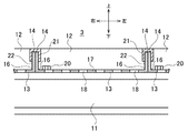
- FIG. 3 is a sectional view taken along line VV of FIG. It is an example of the arrangement pattern of the vents, (a) shows a staggered arrangement, and (b) shows a grid arrangement. It is a figure which shows typically the structure of the flue gas desulfurization apparatus which concerns on 2nd Embodiment of this invention.
- the front means the inflow side of the exhaust gas in the absorption tower 1
- the left and right means the left and right when viewed from the front to the rear.
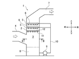
- the flue gas desulfurization apparatus is a wet limestone-plaster flue gas desulfurization apparatus that removes sulfur oxides from exhaust gas containing sulfur oxides generated in a thermal power plant or the like, and contains sulfur oxides. It is provided with an absorption tower (desulfurization absorption tower) 1 into which exhaust gas is introduced, and a separation device (not shown) that separates the absorption liquid flowing out from the absorption tower 1 into plaster and a dehydration filtrate.
- the absorption tower 1 has a cylindrical peripheral wall 2 that stands up substantially vertically, and the inner peripheral surface of the peripheral wall 2 partitions a gas flow passage 3 extending in the vertical direction.
- An inlet duct 4 is connected to the front side of the peripheral wall 2, and exhaust gas from a boiler (not shown) is introduced into the gas flow passage 3 via the inlet duct 4. The introduced exhaust gas flows through the gas flow passage 3 from the bottom to the top.
- a spray header 6 provided with a large number of spray nozzles (absorbent liquid supply units) 5 is installed above the gas flow passage 3 in the absorption tower 1, and the absorption liquid is sprayed from the spray nozzle 5 as fine droplets.
- the absorption liquid supply unit of the present embodiment is a spray type in which the absorption liquid is sprayed as fine droplets and the sprayed droplets are brought into contact with the exhaust gas flowing upward, and the absorption liquid supplied from the spray nozzle 5 is used.
- the minute droplets accompanying the exhaust gas flow are removed by a mist eliminator (not shown) installed on the gas outlet side of the absorption tower 1.
- the gas from which minute droplets have been removed by the mist eliminator is heated by a reheating facility (not shown) installed on the wake side of the absorption tower 1 as needed, and discharged from the chimney (not shown).
- a reheating facility not shown
- the absorption liquid staying in the absorption tower tank 8 is sent by the absorption liquid circulation pump 9 and supplied from the absorption liquid circulation pipe 10 to the spray header 6 (spray nozzle 5). Further, the absorption tower tank 8 is provided with an air supply device (not shown) that supplies air to the accumulated absorption liquid.
- a plurality of support beams 11 are arranged in the gas flow passage 3 below the spray nozzle 5.
- the support beam 11 is, for example, a steel material having an I-shaped cross section, extends linearly in the left-right direction (first direction) substantially orthogonal to the vertical direction, and is arranged substantially parallel to the front-rear direction (second direction) of the absorption tower 1. It is fixed to the peripheral wall 2.
- the plurality of support beams 11 are arranged at substantially equal intervals (at equal pitches) in the front-rear direction (second direction) substantially orthogonal to the left-right direction.
- the support beam 11 may be directly fixed to the peripheral wall 2 or may be fixed to the structure (for example, a pillar) of the absorption tower 1 that supports the peripheral wall 2.
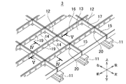
- the liquid retention vent 12 has a rectangular box shape with an upper opening, and is arranged linearly in the left-right direction and linearly in the front-rear direction below the spray nozzle 5. That is, the liquid retention vents 12 are arranged side by side in a plurality of rows in the front-rear and left-right directions so as to fill the circular horizontal plane substantially orthogonal to the flow direction of the exhaust gas. Since the circular horizontal surface is filled with the rectangular box-shaped stagnant gas ventilator 12, the liquid stagnant ventilator 12 arranged on the outermost side is separated from the inner peripheral surface of the peripheral wall 2.
- the outermost liquid retaining body 12 and the peripheral wall may be closed by a shielding plate, or a perforated plate having ventilation holes may be arranged as in the perforated plate portion 13 described later. Further, when the space between the outermost liquid retaining body 12 and the peripheral wall is narrow, it is not necessary to arrange anything as it is.
- each of the liquid retention vents 12 includes a perforated plate portion 13, a pair of long-side standing plate portions (first facing plate portions) 14, and a pair of short-side standing plates. It has a portion (second facing plate portion) 15 integrally.
- the perforated plate portion 13 has a rectangular plate shape in which a pair of long sides (first opposite side) 16 and a pair of short sides (second opposite side) 17 shorter than the long side 16 are orthogonal to each other.
- the long side standing plate portion 14 has a rectangular plate shape that is bent at a substantially right angle from the long side 16 and extends upward.
- the short side upright plate portion 15 has a rectangular plate shape that is bent at a substantially right angle from the short side 17 and extends upward.
- the heights of the long side upright plate portion 14 and the short side upright plate portion 15 from the perforated plate portion 13 can be arbitrarily set, and in the present embodiment, the height of the long side upright plate portion 14 from the perforated plate portion 13
- the height of the short side standing plate portion 15 is set to substantially the same height. Therefore, substantially the entire vertical direction of the long side upright plate portion 14 and substantially the entire vertical direction of the short side upright plate portion 15 can function as partition plates for partitioning the retention space described later.
- a large number of ventilation holes 18 penetrating in the vertical direction are formed in the perforated plate portion 13.
- the arrangement pattern of the ventilation holes 18 can be arbitrarily set such as a staggered shape (see FIG. 6A) or a grid shape (see FIG. 6B).
- the long side standing plate portion 14 is continuously linearly in the front-rear direction
- the short side standing plate portion 15 is continuously linearly in the left-right direction
- two liquid stagnant plates adjacent to each other in the left-right direction The long side upright plate portions 14 of the vent body 12 overlap in the left-right direction
- the short sides 17 of the two liquid retention vents 12 adjacent to each other in the front-rear direction are arranged side by side in the front-rear direction and come into close proximity or contact with each other, and two adjacent in the front-rear direction.
- the short side upright plate portion 15 of the liquid retention vent body 12 overlaps in the front-rear direction
- the short side 17 of the perforated plate portion 13 is arranged so as to be placed on the support beam 11.
- the two long-side standing plate portions 14 that are adjacent to each other in the left-right direction are joined by fastening a plurality of bolts / nuts (coupling members) 19 for fixing the long-sides arranged in the front-rear direction (four locations in this embodiment). .. That is, the four sides of the perforated plate portion 13 are bent to form a pair of long-side standing plate portions 14 and a pair of short-side standing plate portions 15, and adjacent long-side standing plate portions 14 are joined to each other.
- the liquid retention vents 12 arranged in the left-right direction are connected to each row.
- the front end and the rear end of the perforated plate portion 13 are fixed to the support beam 11 by fastening bolts and nuts 20 for fixing the perforated plate.
- the adjacent short side upright plate portions 15 are not connected to each other.
- the absorbing liquid supplied into the exhaust gas from the spray nozzle 5 at the upper part of the gas flow passage 3 comes into gas-liquid contact with the exhaust gas before reaching the stagnant air vent body 12 to form sulfur oxides. Absorb and remove. Further, the absorbed liquid after reaching the liquid retention vent 12 and falling onto the perforated plate portion 13 stays in the liquid retention space surrounded by the long side upright plate portion 14 and the short side upright plate portion 15. Sulfur oxides are absorbed and removed by gas-liquid contact with the exhaust gas at the ventilation holes 18, and the sulfur oxides fall from the ventilation holes 18 to the absorption tower tank 8 below.
- the liquid retention vent 12 is arranged in the gas flow passage 3 in the absorption tower 1 in order to improve the gas-liquid contact efficiency between the exhaust gas and the absorption liquid, the desulfurization performance of the flue gas desulfurization apparatus is improved. be able to.
- the beam structure is formed only by the support beams 11 extending linearly in the left-right direction and arranging substantially in parallel, and the supporting beams (second supporting beams) extending linearly in the front-rear direction and arranging substantially parallel are omitted.
- the long side upright plate portions 14 of the liquid retention vent 12 are arranged continuously in a straight line in the front-rear direction, and the long side upright plate portions 14 overlapping in the left-right direction overlap each other. Is connected by bolts and nuts 19, so that the rigidity of the liquid retention vent 12 (mainly the surface rigidity of the perforated plate portion 13) in the state of being installed in the absorption tower 1 (installed state) is controlled by the long side upright plate portion 14.
- the number of support beams 11 can be reduced as compared with the case of installing a grid-like beam structure, scale (products, dust, etc. generated by gas-liquid contact between the exhaust gas and the absorbing liquid) is generated and adheres.
- the number of easy-to-use support beams 11 can be minimized. Therefore, the scale is less likely to accumulate, blockage of the perforated plate portion 13 (decrease in aperture ratio) can be suppressed, and an increase in pressure loss can be suppressed.
- the blowing capacity (for example, the capacity of the blowing fan) can be kept low.
- Area-the area of the dead space that overlaps the support beam) / the total area of the perforated plate portion x 100%) can be increased. Therefore, when the opening ratios (for example, 41%) of the entire ventilation holes 18 are the same (the same number of ventilation holes 18 having the same shape are provided), the spacing (hole pitch) of the ventilation holes 18 is wider than that of the lattice-shaped beam structure. It is possible to increase the rigidity (strength) of the liquid retention vent body 12.
- the number of ventilation holes 18 can be increased by narrowing the hole pitch and various arrangements of the ventilation holes 18 (rectangular, triangular, etc.). It can respond flexibly.
- the long-side standing plate portion 14 and the short-side standing plate portion 15 play the role of a partition plate (the role of partitioning the liquid retention space), it is not necessary to separately provide a partition plate. As a result, the welded portion for fixing the partition plate is also omitted, and the welded portion easily corroded can be significantly reduced. In addition, distortion due to welding is unlikely to occur, and the man-hours required for distortion correction work (distortion removal) after welding can be reduced.
- the increase in cost can be suppressed by minimizing the number of support beams 11, which is particularly advantageous when an expensive steel material such as stainless steel is used to enhance the durability of the support beams 11.
- the support beam 11 is arranged as compared with the case where the short side upright plate portion 15 is arranged so as to be continuous in the left-right direction.
- the number of support beams 11 can be reduced by increasing the interval (distance between the support beams 11 adjacent to each other in the front-rear direction).
- the long side upright plate portion 14 is responsible for the role of the second support beam instead of the short side upright plate portion 15, the liquid retention body is compared with the case where the short side upright plate portion 15 is in charge of the role of the second support beam.
- the rigidity (strength) of 12 can be increased.
- the plurality of support beams 11 are arranged at substantially equal intervals in the front-rear direction, the plurality of liquid retention vents 12 can have the same shape. Further, since the perforated plate portion 13 is fixed to the support beam 11, the rigidity of the liquid retention vent 12 in the installed state (mainly the surface rigidity of the perforated plate portion 13) can be further increased.
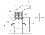
- the flue gas desulfurization apparatus of the second embodiment of the present invention differs from the first embodiment in the shape of the peripheral wall of the absorption tower 1 and the configuration of the absorption liquid supply unit. Therefore, the same components as those in the first embodiment are designated by the same reference numerals, and the description thereof will be omitted.
- the absorption tower 1 has a square (rectangular) peripheral wall in which the front wall and the rear wall separated in the front-rear direction and the left wall and the right wall separated in the left-right direction stand up substantially vertically. 31 is provided, and the inner peripheral surface of the peripheral wall 31 partitions a gas flow passage 3 extending in the vertical direction.
- a spray header 33 having a large number of spray nozzles (absorbent liquid supply units) 32 is installed in the gas flow passage 3 in the absorption tower 1, and a columnar liquid column 34 is discharged from the spray nozzle 32 so that the absorption liquid is discharged upward. To form.
- the absorbing liquid supply unit of the present embodiment generates the liquid column 34 by ejecting the absorbing liquid in a columnar shape from the lower side to the upper side, and brings the generated liquid column 34 into contact with the exhaust gas flowing upward. It is an expression.
- Most of the absorption liquid discharged from the spray nozzle 32 absorbs sulfur oxides, then falls into the absorption tower tank 8 at the lower part of the absorption tower 1, is sent by the absorption liquid circulation pump 9, and is sent from the absorption liquid circulation pipe 10. It is supplied to the spray header 33 (spray nozzle 32).
- the plurality of support beams 11 extend linearly in the left-right direction (first direction), line up substantially parallel to the front-rear direction (second direction), and are fixed to the peripheral wall 31 of the absorption tower 1. Similar to the first embodiment, a plurality of liquid retention vents 12 are placed and supported on the support beam 11. The stagnant liquid vents 12 are arranged side by side in a plurality of rows in the front-rear and left-right directions so as to fill the rectangular horizontal plane substantially orthogonal to the flow direction of the exhaust gas.
- the peripheral wall of the absorption tower 1 is square as in the second embodiment (see FIG. 8), and the absorption liquid supply unit is a spray type as in the first embodiment. (See Fig. 1).
- the peripheral wall of the absorption tower 1 is cylindrical as in the first embodiment (see FIG. 2), and the absorption liquid supply unit is a liquid column as in the second embodiment. It is an equation (see FIG. 7).
- the present invention is not limited to the above-described embodiment and modification described as an example, and is not limited to the above-described embodiment and the like as long as it does not deviate from the technical idea of the present invention. , Various changes are possible depending on the design and the like.
- the short side upright plate portion 15 may not be formed on all of the short side 17s before and after the liquid retention body 12, and the short side upright plate portion 15 may be formed only on a part of the short side 17.
- the short side upright plate portion 15 may be arranged so that the short side upright plate portion 15 is not continuous in the left-right direction (see FIG. 9), and the short side upright plate portion 15 is short so as to be continuous in the left-right direction.
- the side standing plate portion 15 may be arranged (not shown).
- the short side upright plate portion 15 may be arranged so that only one of the front and rear short side upright plate portions 15 (the front side in the example of FIG. 10) remains. ..
- the long-side standing plate portion 14 and the short-side standing plate portion 15 form a liquid retention space in which the absorbing liquid that has fallen on the perforated plate portion 13 can be retained. Can be done.
- the plurality of liquid retention vents 12 need only be arranged linearly in the front-rear direction, and it is optional that they are arranged linearly in the left-right direction.
- the stagnant gas vents 12 may be arranged in a straight line every other in the left-right direction, and the liquid stagnant vents 12 in between may be arranged in a straight line in the same manner.
- the two long-side standing plate portions 14 that are adjacent to each other in the left-right direction and overlap each other are bolts and nuts for fixing a plurality of long-sides arranged in the front-rear direction as in the first embodiment. Combined by fastening 19
- the beam structure may be provided with at least one auxiliary beam (second support beam) 35 which is fixed to the peripheral wall 2 of the absorption tower 1 and extends linearly in the front-rear direction.
- auxiliary beams 35 may be provided so as to be arranged in parallel in the left-right direction.
- the number of auxiliary beams 35 is preferably any number less than the number of support beams 11 and less than the total number of liquid retention absorbers 12 arranged in the left-right direction.
- the connecting member for connecting the two long-side standing plate portions 14 is not limited to the bolts and nuts 19, and is arbitrary.
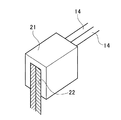
- one or a plurality of fitting members 21 having a U-shaped cross section having a fitting groove 22 slightly narrower than the thickness of two long-side standing plate portions 14 are used 2 Two long-side standing plate portions 14 may be connected. In this case, if the opening of the fitting groove 22 is aligned with the upper end of the stacked long side standing plate portions 14, the fitting member 21 is beaten from above to fit the long side standing plate portion 14 into the fitting groove 22. Good.
- the upper ends of the two long-side standing plate portions 14 that overlap each other may be bent in a direction away from each other, and the upper surface thereof may function as the load receiving surface 23.
- the scaffolding plate material 24 on which the worker can walk may be placed on the load receiving surface 23.
- the liquid retention vent 12 is arranged on one horizontal plane, but the combination of the support beam 11 and the liquid retention vent 12 may be arranged in multiple stages on a plurality of horizontal planes having different heights. Good.
- Absorption tower (desulfurization absorption tower) 2, 31: Peripheral wall 3: Gas flow passage 4: Inlet duct 5, 32: Spray nozzle (absorbent liquid supply unit) 6, 33: Spray header 7: Exhaust gas outlet 8: Absorption tower tank 9: Absorbent liquid circulation pump 10: Absorbent liquid circulation pipe 11: Support beam 12: Retaining liquid ventilator 13: Perforated plate part 14: Long side upright plate part (No.
Landscapes
- Chemical & Material Sciences (AREA)
- Engineering & Computer Science (AREA)
- Chemical Kinetics & Catalysis (AREA)
- Analytical Chemistry (AREA)
- General Chemical & Material Sciences (AREA)
- Oil, Petroleum & Natural Gas (AREA)
- Environmental & Geological Engineering (AREA)
- Health & Medical Sciences (AREA)
- Biomedical Technology (AREA)
- Treating Waste Gases (AREA)
- Gas Separation By Absorption (AREA)
Priority Applications (4)
| Application Number | Priority Date | Filing Date | Title |
|---|---|---|---|
| PCT/JP2019/014219 WO2020202330A1 (ja) | 2019-03-29 | 2019-03-29 | 排煙脱硫装置 |
| JP2021511707A JP7225377B2 (ja) | 2019-03-29 | 2019-03-29 | 排煙脱硫装置 |
| KR1020217034407A KR102620035B1 (ko) | 2019-03-29 | 2019-03-29 | 배연 탈황 장치 |
| TW109110504A TWI738266B (zh) | 2019-03-29 | 2020-03-27 | 排煙脫硫裝置 |
Applications Claiming Priority (1)
| Application Number | Priority Date | Filing Date | Title |
|---|---|---|---|
| PCT/JP2019/014219 WO2020202330A1 (ja) | 2019-03-29 | 2019-03-29 | 排煙脱硫装置 |
Publications (1)
| Publication Number | Publication Date |
|---|---|
| WO2020202330A1 true WO2020202330A1 (ja) | 2020-10-08 |
Family
ID=72666639
Family Applications (1)
| Application Number | Title | Priority Date | Filing Date |
|---|---|---|---|
| PCT/JP2019/014219 Ceased WO2020202330A1 (ja) | 2019-03-29 | 2019-03-29 | 排煙脱硫装置 |
Country Status (4)
| Country | Link |
|---|---|
| JP (1) | JP7225377B2 (https=) |
| KR (1) | KR102620035B1 (https=) |
| TW (1) | TWI738266B (https=) |
| WO (1) | WO2020202330A1 (https=) |
Cited By (1)
| Publication number | Priority date | Publication date | Assignee | Title |
|---|---|---|---|---|
| CN112915733A (zh) * | 2021-04-02 | 2021-06-08 | 中冶赛迪技术研究中心有限公司 | 塔内导流管丛均流结构 |
Families Citing this family (2)
| Publication number | Priority date | Publication date | Assignee | Title |
|---|---|---|---|---|
| KR102757058B1 (ko) * | 2022-04-27 | 2025-01-22 | (주)로우카본 | 석탄가스화 복합발전용 이산화탄소 및 황산화물 포집, 및 탄소자원화 시스템 |
| KR102754860B1 (ko) * | 2022-04-27 | 2025-01-15 | (주)로우카본 | 제철소용 이산화탄소 포집 및 탄소자원화, 및 수소 생산 시스템 |
Citations (6)
| Publication number | Priority date | Publication date | Assignee | Title |
|---|---|---|---|---|
| JPS4965987A (https=) * | 1972-09-13 | 1974-06-26 | ||
| JPS56205U (https=) * | 1979-06-13 | 1981-01-06 | ||
| JPS5654901U (https=) * | 1979-10-03 | 1981-05-13 | ||
| JPH0810502A (ja) * | 1994-07-04 | 1996-01-16 | Jgc Corp | 棚段塔およびその組立方法 |
| JPH09155142A (ja) * | 1995-12-07 | 1997-06-17 | Idemitsu Eng Co Ltd | 気液接触による特定成分除去方法並びに除去装置及び該装置に用いるトレイ |
| US20090309245A1 (en) * | 2008-06-16 | 2009-12-17 | Johnson Ronald B | Wet scrubber tray |
Family Cites Families (5)
| Publication number | Priority date | Publication date | Assignee | Title |
|---|---|---|---|---|
| US4263021A (en) | 1972-12-05 | 1981-04-21 | The Babcock & Wilcox Company | Gas-liquid contact system |
| JP2006122862A (ja) * | 2004-11-01 | 2006-05-18 | Mitsubishi Heavy Ind Ltd | 排ガス処理装置 |
| JP5725725B2 (ja) * | 2010-04-07 | 2015-05-27 | 三菱日立パワーシステムズ株式会社 | 湿式排煙脱硫装置 |
| CN102489141B (zh) | 2011-12-10 | 2014-03-26 | 程爱平 | 喷淋式脱硫吸收塔浆液收集盘 |
| CN203591693U (zh) | 2013-08-19 | 2014-05-14 | 武汉龙净环保工程有限公司 | 脱硫吸收塔 |
-
2019
- 2019-03-29 KR KR1020217034407A patent/KR102620035B1/ko active Active
- 2019-03-29 WO PCT/JP2019/014219 patent/WO2020202330A1/ja not_active Ceased
- 2019-03-29 JP JP2021511707A patent/JP7225377B2/ja active Active
-
2020
- 2020-03-27 TW TW109110504A patent/TWI738266B/zh active
Patent Citations (6)
| Publication number | Priority date | Publication date | Assignee | Title |
|---|---|---|---|---|
| JPS4965987A (https=) * | 1972-09-13 | 1974-06-26 | ||
| JPS56205U (https=) * | 1979-06-13 | 1981-01-06 | ||
| JPS5654901U (https=) * | 1979-10-03 | 1981-05-13 | ||
| JPH0810502A (ja) * | 1994-07-04 | 1996-01-16 | Jgc Corp | 棚段塔およびその組立方法 |
| JPH09155142A (ja) * | 1995-12-07 | 1997-06-17 | Idemitsu Eng Co Ltd | 気液接触による特定成分除去方法並びに除去装置及び該装置に用いるトレイ |
| US20090309245A1 (en) * | 2008-06-16 | 2009-12-17 | Johnson Ronald B | Wet scrubber tray |
Cited By (1)
| Publication number | Priority date | Publication date | Assignee | Title |
|---|---|---|---|---|
| CN112915733A (zh) * | 2021-04-02 | 2021-06-08 | 中冶赛迪技术研究中心有限公司 | 塔内导流管丛均流结构 |
Also Published As
| Publication number | Publication date |
|---|---|
| JP7225377B2 (ja) | 2023-02-20 |
| JPWO2020202330A1 (https=) | 2020-10-08 |
| KR102620035B1 (ko) | 2023-12-29 |
| TWI738266B (zh) | 2021-09-01 |
| TW202103776A (zh) | 2021-02-01 |
| KR20210141680A (ko) | 2021-11-23 |
Similar Documents
| Publication | Publication Date | Title |
|---|---|---|
| US8777190B2 (en) | Wet scrubber tray | |
| WO2020202330A1 (ja) | 排煙脱硫装置 | |
| US6923852B2 (en) | Flue gas desulfurization system with a stepped tray | |
| EP2463014A1 (en) | A wet scrubber comprising deflector plates, and a method of cleaning a process gas | |
| JP5725725B2 (ja) | 湿式排煙脱硫装置 | |
| US10480816B2 (en) | Method and system for reducing moisture carryover in air handlers | |
| US20080264260A1 (en) | Droplet Separator Installation | |
| JP4642559B2 (ja) | 不純物除去装置 | |
| JP7121739B2 (ja) | 冷却塔 | |
| JP4905926B2 (ja) | 二室型湿式排煙脱硫装置 | |
| JP6878709B1 (ja) | 排煙脱硫装置 | |
| JP2548163B2 (ja) | スプレ−式脱硫塔 | |
| JP2016080312A (ja) | 冷却塔 | |
| JP3904771B2 (ja) | 二室型湿式排煙脱硫装置 | |
| CN111330358B (zh) | 一种脱硫除尘设备 | |
| JPH119955A (ja) | 排煙脱硫装置のスプレ式角型吸収塔 | |
| JPH09117635A (ja) | 塔内循環スプレ管構造 | |
| CN206342990U (zh) | 一种脱硫塔除雾器 | |
| CN220310059U (zh) | 一种粉尘废气净化系统 | |
| JP2001017828A (ja) | 二室型湿式排煙脱硫装置 | |
| ZA200904174B (en) | Wet scrubber tray | |
| JP7091280B2 (ja) | 吸収塔の排ガス入口構造 | |
| JP2017140583A (ja) | 塗装ミスト捕集装置 |
Legal Events
| Date | Code | Title | Description |
|---|---|---|---|
| 121 | Ep: the epo has been informed by wipo that ep was designated in this application |
Ref document number: 19922811 Country of ref document: EP Kind code of ref document: A1 |
|
| ENP | Entry into the national phase |
Ref document number: 2021511707 Country of ref document: JP Kind code of ref document: A |
|
| NENP | Non-entry into the national phase |
Ref country code: DE |
|
| ENP | Entry into the national phase |
Ref document number: 20217034407 Country of ref document: KR Kind code of ref document: A |
|
| 122 | Ep: pct application non-entry in european phase |
Ref document number: 19922811 Country of ref document: EP Kind code of ref document: A1 |