WO2020196773A1 - 方向性電磁鋼板の製造方法および焼鈍分離剤の塗布設備 - Google Patents
方向性電磁鋼板の製造方法および焼鈍分離剤の塗布設備 Download PDFInfo
- Publication number
- WO2020196773A1 WO2020196773A1 PCT/JP2020/013750 JP2020013750W WO2020196773A1 WO 2020196773 A1 WO2020196773 A1 WO 2020196773A1 JP 2020013750 W JP2020013750 W JP 2020013750W WO 2020196773 A1 WO2020196773 A1 WO 2020196773A1
- Authority
- WO
- WIPO (PCT)
- Prior art keywords
- steel sheet
- annealing
- annealing separator
- additive
- separator
- Prior art date
- Legal status (The legal status is an assumption and is not a legal conclusion. Google has not performed a legal analysis and makes no representation as to the accuracy of the status listed.)
- Ceased
Links
Images





Classifications
-
- C—CHEMISTRY; METALLURGY
- C22—METALLURGY; FERROUS OR NON-FERROUS ALLOYS; TREATMENT OF ALLOYS OR NON-FERROUS METALS
- C22C—ALLOYS
- C22C38/00—Ferrous alloys, e.g. steel alloys
- C22C38/06—Ferrous alloys, e.g. steel alloys containing aluminium
-
- B—PERFORMING OPERATIONS; TRANSPORTING
- B21—MECHANICAL METAL-WORKING WITHOUT ESSENTIALLY REMOVING MATERIAL; PUNCHING METAL
- B21C—MANUFACTURE OF METAL SHEETS, WIRE, RODS, TUBES, PROFILES OR LIKE SEMI-MANUFACTURED PRODUCTS OTHERWISE THAN BY ROLLING; AUXILIARY OPERATIONS USED IN CONNECTION WITH METAL-WORKING WITHOUT ESSENTIALLY REMOVING MATERIAL
- B21C47/00—Winding-up, coiling or winding-off metal wire, metal band or other flexible metal material characterised by features relevant to metal processing only
- B21C47/02—Winding-up or coiling
-
- C—CHEMISTRY; METALLURGY
- C21—METALLURGY OF IRON
- C21D—MODIFYING THE PHYSICAL STRUCTURE OF FERROUS METALS; GENERAL DEVICES FOR HEAT TREATMENT OF FERROUS OR NON-FERROUS METALS OR ALLOYS; MAKING METAL MALLEABLE, e.g. BY DECARBURISATION OR TEMPERING
- C21D6/00—Heat treatment of ferrous alloys
- C21D6/005—Heat treatment of ferrous alloys containing Mn
-
- C—CHEMISTRY; METALLURGY
- C21—METALLURGY OF IRON
- C21D—MODIFYING THE PHYSICAL STRUCTURE OF FERROUS METALS; GENERAL DEVICES FOR HEAT TREATMENT OF FERROUS OR NON-FERROUS METALS OR ALLOYS; MAKING METAL MALLEABLE, e.g. BY DECARBURISATION OR TEMPERING
- C21D6/00—Heat treatment of ferrous alloys
- C21D6/008—Heat treatment of ferrous alloys containing Si
-
- C—CHEMISTRY; METALLURGY
- C21—METALLURGY OF IRON
- C21D—MODIFYING THE PHYSICAL STRUCTURE OF FERROUS METALS; GENERAL DEVICES FOR HEAT TREATMENT OF FERROUS OR NON-FERROUS METALS OR ALLOYS; MAKING METAL MALLEABLE, e.g. BY DECARBURISATION OR TEMPERING
- C21D8/00—Modifying the physical properties of ferrous metals or ferrous alloys by deformation combined with, or followed by, heat treatment
-
- C—CHEMISTRY; METALLURGY
- C21—METALLURGY OF IRON
- C21D—MODIFYING THE PHYSICAL STRUCTURE OF FERROUS METALS; GENERAL DEVICES FOR HEAT TREATMENT OF FERROUS OR NON-FERROUS METALS OR ALLOYS; MAKING METAL MALLEABLE, e.g. BY DECARBURISATION OR TEMPERING
- C21D8/00—Modifying the physical properties of ferrous metals or ferrous alloys by deformation combined with, or followed by, heat treatment
- C21D8/12—Modifying the physical properties of ferrous metals or ferrous alloys by deformation combined with, or followed by, heat treatment during manufacturing of articles with special electromagnetic properties
- C21D8/1216—Modifying the physical properties of ferrous metals or ferrous alloys by deformation combined with, or followed by, heat treatment during manufacturing of articles with special electromagnetic properties characterised by the working steps
- C21D8/1222—Hot rolling
-
- C—CHEMISTRY; METALLURGY
- C21—METALLURGY OF IRON
- C21D—MODIFYING THE PHYSICAL STRUCTURE OF FERROUS METALS; GENERAL DEVICES FOR HEAT TREATMENT OF FERROUS OR NON-FERROUS METALS OR ALLOYS; MAKING METAL MALLEABLE, e.g. BY DECARBURISATION OR TEMPERING
- C21D8/00—Modifying the physical properties of ferrous metals or ferrous alloys by deformation combined with, or followed by, heat treatment
- C21D8/12—Modifying the physical properties of ferrous metals or ferrous alloys by deformation combined with, or followed by, heat treatment during manufacturing of articles with special electromagnetic properties
- C21D8/1216—Modifying the physical properties of ferrous metals or ferrous alloys by deformation combined with, or followed by, heat treatment during manufacturing of articles with special electromagnetic properties characterised by the working steps
- C21D8/1233—Cold rolling
-
- C—CHEMISTRY; METALLURGY
- C21—METALLURGY OF IRON
- C21D—MODIFYING THE PHYSICAL STRUCTURE OF FERROUS METALS; GENERAL DEVICES FOR HEAT TREATMENT OF FERROUS OR NON-FERROUS METALS OR ALLOYS; MAKING METAL MALLEABLE, e.g. BY DECARBURISATION OR TEMPERING
- C21D8/00—Modifying the physical properties of ferrous metals or ferrous alloys by deformation combined with, or followed by, heat treatment
- C21D8/12—Modifying the physical properties of ferrous metals or ferrous alloys by deformation combined with, or followed by, heat treatment during manufacturing of articles with special electromagnetic properties
- C21D8/1244—Modifying the physical properties of ferrous metals or ferrous alloys by deformation combined with, or followed by, heat treatment during manufacturing of articles with special electromagnetic properties characterised by the heat treatment
- C21D8/1272—Final recrystallisation annealing
-
- C—CHEMISTRY; METALLURGY
- C21—METALLURGY OF IRON
- C21D—MODIFYING THE PHYSICAL STRUCTURE OF FERROUS METALS; GENERAL DEVICES FOR HEAT TREATMENT OF FERROUS OR NON-FERROUS METALS OR ALLOYS; MAKING METAL MALLEABLE, e.g. BY DECARBURISATION OR TEMPERING
- C21D8/00—Modifying the physical properties of ferrous metals or ferrous alloys by deformation combined with, or followed by, heat treatment
- C21D8/12—Modifying the physical properties of ferrous metals or ferrous alloys by deformation combined with, or followed by, heat treatment during manufacturing of articles with special electromagnetic properties
- C21D8/1277—Modifying the physical properties of ferrous metals or ferrous alloys by deformation combined with, or followed by, heat treatment during manufacturing of articles with special electromagnetic properties involving a particular surface treatment
- C21D8/1283—Application of a separating or insulating coating
-
- C—CHEMISTRY; METALLURGY
- C21—METALLURGY OF IRON
- C21D—MODIFYING THE PHYSICAL STRUCTURE OF FERROUS METALS; GENERAL DEVICES FOR HEAT TREATMENT OF FERROUS OR NON-FERROUS METALS OR ALLOYS; MAKING METAL MALLEABLE, e.g. BY DECARBURISATION OR TEMPERING
- C21D9/00—Heat treatment, e.g. annealing, hardening, quenching or tempering, adapted for particular articles; Furnaces therefor
- C21D9/46—Heat treatment, e.g. annealing, hardening, quenching or tempering, adapted for particular articles; Furnaces therefor for sheet metals
-
- C—CHEMISTRY; METALLURGY
- C22—METALLURGY; FERROUS OR NON-FERROUS ALLOYS; TREATMENT OF ALLOYS OR NON-FERROUS METALS
- C22C—ALLOYS
- C22C38/00—Ferrous alloys, e.g. steel alloys
-
- C—CHEMISTRY; METALLURGY
- C22—METALLURGY; FERROUS OR NON-FERROUS ALLOYS; TREATMENT OF ALLOYS OR NON-FERROUS METALS
- C22C—ALLOYS
- C22C38/00—Ferrous alloys, e.g. steel alloys
- C22C38/001—Ferrous alloys, e.g. steel alloys containing N
-
- C—CHEMISTRY; METALLURGY
- C22—METALLURGY; FERROUS OR NON-FERROUS ALLOYS; TREATMENT OF ALLOYS OR NON-FERROUS METALS
- C22C—ALLOYS
- C22C38/00—Ferrous alloys, e.g. steel alloys
- C22C38/002—Ferrous alloys, e.g. steel alloys containing In, Mg, or other elements not provided for in one single group C22C38/001 - C22C38/60
-
- C—CHEMISTRY; METALLURGY
- C22—METALLURGY; FERROUS OR NON-FERROUS ALLOYS; TREATMENT OF ALLOYS OR NON-FERROUS METALS
- C22C—ALLOYS
- C22C38/00—Ferrous alloys, e.g. steel alloys
- C22C38/02—Ferrous alloys, e.g. steel alloys containing silicon
-
- C—CHEMISTRY; METALLURGY
- C22—METALLURGY; FERROUS OR NON-FERROUS ALLOYS; TREATMENT OF ALLOYS OR NON-FERROUS METALS
- C22C—ALLOYS
- C22C38/00—Ferrous alloys, e.g. steel alloys
- C22C38/04—Ferrous alloys, e.g. steel alloys containing manganese
-
- C—CHEMISTRY; METALLURGY
- C22—METALLURGY; FERROUS OR NON-FERROUS ALLOYS; TREATMENT OF ALLOYS OR NON-FERROUS METALS
- C22C—ALLOYS
- C22C38/00—Ferrous alloys, e.g. steel alloys
- C22C38/12—Ferrous alloys, e.g. steel alloys containing tungsten, tantalum, molybdenum, vanadium, or niobium
-
- C—CHEMISTRY; METALLURGY
- C22—METALLURGY; FERROUS OR NON-FERROUS ALLOYS; TREATMENT OF ALLOYS OR NON-FERROUS METALS
- C22C—ALLOYS
- C22C38/00—Ferrous alloys, e.g. steel alloys
- C22C38/60—Ferrous alloys, e.g. steel alloys containing lead, selenium, tellurium, or antimony, or more than 0.04% by weight of sulfur
-
- C—CHEMISTRY; METALLURGY
- C23—COATING METALLIC MATERIAL; COATING MATERIAL WITH METALLIC MATERIAL; CHEMICAL SURFACE TREATMENT; DIFFUSION TREATMENT OF METALLIC MATERIAL; COATING BY VACUUM EVAPORATION, BY SPUTTERING, BY ION IMPLANTATION OR BY CHEMICAL VAPOUR DEPOSITION, IN GENERAL; INHIBITING CORROSION OF METALLIC MATERIAL OR INCRUSTATION IN GENERAL
- C23C—COATING METALLIC MATERIAL; COATING MATERIAL WITH METALLIC MATERIAL; SURFACE TREATMENT OF METALLIC MATERIAL BY DIFFUSION INTO THE SURFACE, BY CHEMICAL CONVERSION OR SUBSTITUTION; COATING BY VACUUM EVAPORATION, BY SPUTTERING, BY ION IMPLANTATION OR BY CHEMICAL VAPOUR DEPOSITION, IN GENERAL
- C23C22/00—Chemical surface treatment of metallic material by reaction of the surface with a reactive liquid, leaving reaction products of surface material in the coating, e.g. conversion coatings, passivation of metals
-
- C—CHEMISTRY; METALLURGY
- C23—COATING METALLIC MATERIAL; COATING MATERIAL WITH METALLIC MATERIAL; CHEMICAL SURFACE TREATMENT; DIFFUSION TREATMENT OF METALLIC MATERIAL; COATING BY VACUUM EVAPORATION, BY SPUTTERING, BY ION IMPLANTATION OR BY CHEMICAL VAPOUR DEPOSITION, IN GENERAL; INHIBITING CORROSION OF METALLIC MATERIAL OR INCRUSTATION IN GENERAL
- C23C—COATING METALLIC MATERIAL; COATING MATERIAL WITH METALLIC MATERIAL; SURFACE TREATMENT OF METALLIC MATERIAL BY DIFFUSION INTO THE SURFACE, BY CHEMICAL CONVERSION OR SUBSTITUTION; COATING BY VACUUM EVAPORATION, BY SPUTTERING, BY ION IMPLANTATION OR BY CHEMICAL VAPOUR DEPOSITION, IN GENERAL
- C23C22/00—Chemical surface treatment of metallic material by reaction of the surface with a reactive liquid, leaving reaction products of surface material in the coating, e.g. conversion coatings, passivation of metals
- C23C22/73—Chemical surface treatment of metallic material by reaction of the surface with a reactive liquid, leaving reaction products of surface material in the coating, e.g. conversion coatings, passivation of metals characterised by the process
-
- C—CHEMISTRY; METALLURGY
- C23—COATING METALLIC MATERIAL; COATING MATERIAL WITH METALLIC MATERIAL; CHEMICAL SURFACE TREATMENT; DIFFUSION TREATMENT OF METALLIC MATERIAL; COATING BY VACUUM EVAPORATION, BY SPUTTERING, BY ION IMPLANTATION OR BY CHEMICAL VAPOUR DEPOSITION, IN GENERAL; INHIBITING CORROSION OF METALLIC MATERIAL OR INCRUSTATION IN GENERAL
- C23C—COATING METALLIC MATERIAL; COATING MATERIAL WITH METALLIC MATERIAL; SURFACE TREATMENT OF METALLIC MATERIAL BY DIFFUSION INTO THE SURFACE, BY CHEMICAL CONVERSION OR SUBSTITUTION; COATING BY VACUUM EVAPORATION, BY SPUTTERING, BY ION IMPLANTATION OR BY CHEMICAL VAPOUR DEPOSITION, IN GENERAL
- C23C22/00—Chemical surface treatment of metallic material by reaction of the surface with a reactive liquid, leaving reaction products of surface material in the coating, e.g. conversion coatings, passivation of metals
- C23C22/73—Chemical surface treatment of metallic material by reaction of the surface with a reactive liquid, leaving reaction products of surface material in the coating, e.g. conversion coatings, passivation of metals characterised by the process
- C23C22/77—Controlling or regulating of the coating process
-
- H—ELECTRICITY
- H01—ELECTRIC ELEMENTS
- H01F—MAGNETS; INDUCTANCES; TRANSFORMERS; SELECTION OF MATERIALS FOR THEIR MAGNETIC PROPERTIES
- H01F1/00—Magnets or magnetic bodies characterised by the magnetic materials therefor; Selection of materials for their magnetic properties
- H01F1/01—Magnets or magnetic bodies characterised by the magnetic materials therefor; Selection of materials for their magnetic properties of inorganic materials
- H01F1/03—Magnets or magnetic bodies characterised by the magnetic materials therefor; Selection of materials for their magnetic properties of inorganic materials characterised by their coercivity
- H01F1/12—Magnets or magnetic bodies characterised by the magnetic materials therefor; Selection of materials for their magnetic properties of inorganic materials characterised by their coercivity of soft-magnetic materials
- H01F1/14—Magnets or magnetic bodies characterised by the magnetic materials therefor; Selection of materials for their magnetic properties of inorganic materials characterised by their coercivity of soft-magnetic materials metals or alloys
- H01F1/147—Alloys characterised by their composition
-
- H—ELECTRICITY
- H01—ELECTRIC ELEMENTS
- H01F—MAGNETS; INDUCTANCES; TRANSFORMERS; SELECTION OF MATERIALS FOR THEIR MAGNETIC PROPERTIES
- H01F1/00—Magnets or magnetic bodies characterised by the magnetic materials therefor; Selection of materials for their magnetic properties
- H01F1/01—Magnets or magnetic bodies characterised by the magnetic materials therefor; Selection of materials for their magnetic properties of inorganic materials
- H01F1/03—Magnets or magnetic bodies characterised by the magnetic materials therefor; Selection of materials for their magnetic properties of inorganic materials characterised by their coercivity
- H01F1/12—Magnets or magnetic bodies characterised by the magnetic materials therefor; Selection of materials for their magnetic properties of inorganic materials characterised by their coercivity of soft-magnetic materials
- H01F1/14—Magnets or magnetic bodies characterised by the magnetic materials therefor; Selection of materials for their magnetic properties of inorganic materials characterised by their coercivity of soft-magnetic materials metals or alloys
- H01F1/16—Magnets or magnetic bodies characterised by the magnetic materials therefor; Selection of materials for their magnetic properties of inorganic materials characterised by their coercivity of soft-magnetic materials metals or alloys in the form of sheets
- H01F1/18—Magnets or magnetic bodies characterised by the magnetic materials therefor; Selection of materials for their magnetic properties of inorganic materials characterised by their coercivity of soft-magnetic materials metals or alloys in the form of sheets with insulating coating
-
- H—ELECTRICITY
- H01—ELECTRIC ELEMENTS
- H01F—MAGNETS; INDUCTANCES; TRANSFORMERS; SELECTION OF MATERIALS FOR THEIR MAGNETIC PROPERTIES
- H01F41/00—Apparatus or processes specially adapted for manufacturing or assembling magnets, inductances or transformers; Apparatus or processes specially adapted for manufacturing materials characterised by their magnetic properties
- H01F41/02—Apparatus or processes specially adapted for manufacturing or assembling magnets, inductances or transformers; Apparatus or processes specially adapted for manufacturing materials characterised by their magnetic properties for manufacturing cores, coils, or magnets
-
- C—CHEMISTRY; METALLURGY
- C22—METALLURGY; FERROUS OR NON-FERROUS ALLOYS; TREATMENT OF ALLOYS OR NON-FERROUS METALS
- C22C—ALLOYS
- C22C2202/00—Physical properties
- C22C2202/02—Magnetic
-
- Y—GENERAL TAGGING OF NEW TECHNOLOGICAL DEVELOPMENTS; GENERAL TAGGING OF CROSS-SECTIONAL TECHNOLOGIES SPANNING OVER SEVERAL SECTIONS OF THE IPC; TECHNICAL SUBJECTS COVERED BY FORMER USPC CROSS-REFERENCE ART COLLECTIONS [XRACs] AND DIGESTS
- Y02—TECHNOLOGIES OR APPLICATIONS FOR MITIGATION OR ADAPTATION AGAINST CLIMATE CHANGE
- Y02P—CLIMATE CHANGE MITIGATION TECHNOLOGIES IN THE PRODUCTION OR PROCESSING OF GOODS
- Y02P10/00—Technologies related to metal processing
- Y02P10/20—Recycling
Definitions
- the present invention provides a method for manufacturing a grain-oriented electrical steel sheet, which can make the coating characteristics and magnetic properties of grain-oriented electrical steel sheets used for iron cores of transformers uniform and good over the entire length and / or width of the steel sheet. Regarding equipment for applying annealing separators.
- the grain-oriented electrical steel sheet is used as a soft magnetic material mainly as an iron core material of a transformer or a rotating machine, and is required to have a high magnetic flux density and a small iron loss and magnetostriction as magnetic characteristics. For that purpose, it is necessary to form a texture called the so-called Goth orientation, in which the ⁇ 001> axis, which is the axis for easy magnetization, is highly aligned in the rolling direction by secondary recrystallization.
- Such a directional electromagnetic steel sheet is obtained by heating a directional silicon steel slab containing an inhibitor required for secondary recrystallization, for example, MnS, MnSe, AlN, etc., performing hot rolling, and then annealing as necessary.
- the final product thickness is obtained by cold rolling once or two or more times with intermediate annealing in between, and then decarburization annealing is performed, and then an annealing separator such as MgO is applied to the steel sheet, and then finish annealing is performed.
- annealing separator such as MgO
- MgO annealing separator
- finish annealing is performed.
- forsterite coating Quality insulating film
- This coating not only electrically insulates the surface, but also effectively improves iron loss and magnetostriction by applying tensile stress to the steel sheet by utilizing its low thermal expansion property.
- This forsterite film is formed by finish annealing, but its film formation behavior affects the behavior of inhibitors such as MnS, MnSe, and AlN in steel, so it is an essential process for obtaining excellent magnetic properties. It also affects the secondary recrystallization itself. That is, the forsterite formation reaction starts from the process of raising the temperature of the finish annealing, but when the forsterite film formed during the finish annealing becomes porous or when the film formation progresses unevenly, the annealing atmosphere Since O and N easily invade the steel, the annealing in the steel decomposes, becomes coarse, or becomes excessive.
- the obtained secondary recrystallization structure has a low degree of integration in the Goth orientation, and the magnetic characteristics also deteriorate.
- the formation of the coating causes the unnecessary inhibitor component to be concentrated in the vicinity of the coating, substantially purifying the steel. This also contributes to further improvement of the magnetic properties of the steel sheet. Therefore, controlling this film forming process to uniformly form the forsterite film is one of the important points that affect the product quality of grain-oriented electrical steel sheets.
- the formed forsterite coating must, of course, be uniform, defect-free, and have excellent adhesion to withstand shearing, punching, bending, etc., and be distorted by the user. It must have little deterioration of magnetic properties due to annealing, have a smooth surface, and show a high space factor when laminated as an iron core.
- Patent Document 1 the method of applying mainly a roll coater is disclosed in Patent Document 1
- Patent Document 2 the method of attaching by a spray nozzle is disclosed in Patent Document 2.
- the annealing separator can be applied uniformly, as long as the coil-shaped and batch-type finish annealing is performed, the annealing conditions differ depending on the coil portion, so that the forsterite coating is uniform over the entire length and / or width. It is very difficult to form and secondary recrystallize. If the amount of additive aid that is effective for increasing the reactivity of the coil middle winding portion, which tends to delay heat rise and has poor atmospheric gas flowability, is increased, the reaction will be excessive in the coil outer winding portion. The reverse is also true.
- the components of the annealing separator are changed in the longitudinal direction and / or width direction of the steel sheet so that the annealing separator can be attached with the optimum composition for each coil part, and the coating is not applied uniformly.
- Patent Document 2 proposes a method in which a plurality of spray nozzles are arranged and each spray nozzle discharges a component of a different annealing separator to deal with a coating quality deviation of the coil.
- a plurality of spray nozzles are arranged and a liquid or slurry annealing separator is applied, the coating film thickness fluctuates in the width direction of the steel sheet, and during flattening annealing after finish annealing. , The problem of wrinkled shape defects along the longitudinal direction of the steel sheet is likely to occur.
- the MgO-based slurry is sprayed for a long time, sludge accumulates in the supply pipe, which causes problems such as hindering uniform slurry supply and blocking the spray nozzle, so that stable operation cannot be performed.
- Japanese Patent No. 4501655 discloses a technique for changing the component of the annealing separator applied from the innermost winding portion of the coil to the outermost winding portion of the coil at a position where the outer diameter of the coil is 90%. .. It is true that this technique is effective in eliminating the magnetic characteristic deviation in the longitudinal direction of the steel sheet, but it cannot eliminate the magnetic characteristic deviation and the coating characteristic deviation in the width direction.
- the present invention solves the above-mentioned problems, and is a method for manufacturing a grain-oriented electrical steel sheet, which can obtain a grain-oriented electrical steel sheet having uniform coating characteristics and magnetic properties over the entire length and / or width of the steel sheet. And to provide equipment for applying annealing separators.
- the gist structure of the present invention is as follows. (1) A steel slab having a predetermined composition is hot-rolled to obtain a hot-rolled steel sheet, and the hot-rolled steel sheet is cold-rolled once or two or more times with intermediate quenching sandwiched between them. Then, the cold-rolled steel sheet is subjected to primary recrystallization quenching, and after the cold-rolled steel sheet after the primary recrystallization annealing is coated with a liquid or slurry-like quenching separator, the steel sheet is wound into a coil to be finished and annealed.
- an additive for changing the components of the annealing separator is added to the total of the annealing separator and the additive. It is characterized in that it is added in a range of 15% or less by weight of the additive, and the components of the annealing separator are varied and adhered in the longitudinal direction and / or the width direction of the cold-rolled steel sheet after the primary recrystallization annealing. Annealing method for manufacturing electromagnetic steel sheets.
- the main equipment for applying the liquid or slurry annealing separator to the steel sheet and the additive for changing the components of the annealing separator are added to the total of the annealing separator and the additive. It is characterized by providing an auxiliary facility for adding the additive in a weight ratio of 15% or less, and varying and adhering the components of the annealing separator in the longitudinal direction and / or the width direction of the steel sheet. Equipment for applying annealing separators.
- the “% and ppm” indications relating to the components of the steel sheet and the components of the annealing separator shall mean mass% (mass%) and mass ppm (massppm) unless otherwise specified.
- A) was evenly applied with a roll coater, and a dried and baked standard material was prepared.
- 10 mass% magnesia slurry (B) in which only TiO 2 : 7 parts by weight was added to 100 parts by weight of MgO, and TiO 2 : 7 parts by weight and Mg: 1 weight by weight of MgO: 100 parts by weight.
- 10 mass% magnesia slurry (C) to which parts were added, and 10 mass% magnesia slurry (D) to which TiO 2 : 7 parts by weight and Mg sulfate: 2 parts by weight were added to 100 parts by weight of MgO.
- An aqueous magnesium sulfate solution having a concentration was prepared.
- magnesia slurries (B) to (D) are uniformly applied to the decarburized and annealed plate with a roll coater, and then magnesium sulfate is added so as to be the total weight part of the mixed magnesium sulfate shown in Table 1.
- the ratio of the aqueous solution and the concentration of the magnesium sulfate aqueous solution were adjusted, and the magnesium sulfate aqueous solution was sprayed uniformly, and then dried and baked.
- the "ratio (%) of the magnesium sulfate aqueous solution” is the weight ratio of the spray-sprayed magnesium sulfate aqueous solution to the total of the magnesia slurry coated with the roll coater and the spray-sprayed magnesium sulfate aqueous solution, and is "sulfate.
- the "total weight part of Mg” is the total weight part of Mg sulfate derived from the magnesia slurry and the aqueous magnesium sulfate solution.
- the equipment for applying the annealing separator separates the main equipment for applying the liquid or slurry annealing separator to the steel sheet and the additive for changing the components of the annealing separator.
- Auxiliary equipment for attaching the steel sheet by varying it in the longitudinal direction and / or the width direction in the range of 15% or less by weight with respect to the agent is provided. The main equipment and auxiliary equipment will be described in detail below.
- the main equipment As the main equipment, a known spray type or roll coater type coating device can be used, but when a magnesia slurry mainly composed of MgO is used as the annealing separator, sludge and the like tend to accumulate in the supply pipe. It is preferable to use a roll coater type coating device rather than a spray type in which the supply pipe is easily blocked.
- the main equipment can include a slurry supply nozzle and a squeeze roll.
- the slurry supply nozzle has a plurality of discharge ports for applying magnesia slurry to the steel strip.
- the squeeze roll includes a pair of rolls that sandwich the steel strip in the thickness direction and uniformly squeeze the magnesia slurry applied to the steel strip to a predetermined thickness.
- the squeeze roll can be composed of a rough coating roll and a coating roll.
- only one of the rough coating roll and the coating roll may be installed, or an additional slurry supply nozzle may be installed between the rough coating roll and the coating roll. You can also do it.
- This main equipment can be arranged on the downstream side of the continuous annealing furnace used for decarburization annealing described later, and on the upstream side of the drying furnace for drying the annealing separator.
- auxiliary equipment considering the mixing of the annealing separator and the additive, it is preferable to use a spray device capable of adhering the liquid additive auxiliary to the steel strip while adjusting the spray amount.
- the preferable range of the spray amount (adhesion weight per unit area) of the spray device is within 15% of the weight per unit area of the magnesia slurry coated using the main equipment. Since the MgO-based slurry applied in the main equipment has a high specific gravity and a high viscosity, when the diluent is sprayed by a spray or the like, if it exceeds 15%, there is a problem that the slurry is not uniformly mixed by baking and drying.
- the auxiliary equipment can be appropriately divided and arranged according to the required accuracy of the coating characteristics and the magnetic characteristics in the width direction of the steel strip, and is arranged on the upper surface side and the lower surface side of the steel strip as necessary. be able to. It should be noted that the auxiliary equipment does not need to be arranged evenly divided in the width direction, and may be arranged only at the edge and the central portion. Further, when the auxiliary aqueous solution is not one kind, it may precipitate or the pH may become unstable.
- two or more kinds of spray devices may be arranged on the upstream and downstream edges.
- the auxiliary equipment is on the upstream side or the downstream side of the main equipment, or when a squeeze roll composed of a rough coating roll and a coating roll is used as the main equipment, the auxiliary equipment is a rough coating roll and a coating roll. It can be appropriately arranged between and.
- the auxiliary equipment needs to be arranged on the upstream side of the drying furnace.
- the auxiliary equipment may be arranged on the downstream side of the main equipment. preferable.
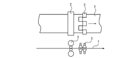
- FIG. 1A shows an example in which the spray device 3 and the coating roll 2 are arranged in this order from the upstream side in the transport direction of the steel strip 1.
- FIGS. 1B and 1C are examples in which the coating roll 2 and the spray device 3 are arranged in this order from the upstream side in the transport direction of the steel strip 1.
- FIGS. 1A and 1B are examples in which the additive is directly attached to the upper and lower surfaces of the steel strip 1.
- FIGS. 1A to 1C shows an example in which a spray device 3 is arranged in the vicinity of the coating roll 2 in order to promote mixing of the annealing separator and the additive, and the additive sprayed from the spray device 3 is involved in the annealing separator. It is preferable that the position of the coating roll 2 and the position of the spray device 3 are closer to each other. Further, in FIGS. 1A to 1C, the slurry supply nozzle and the coating roll are integrated.
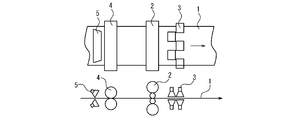
- FIGS. 2A to 2C show a method in which the rough coating roll 4 and the slurry supply nozzle 5 are separated, and the slurry is applied to the steel strip 1 more uniformly as compared with the method of only the coating roll 2 shown in FIGS. 1A to 1C. And the thickness of the slurry can be controlled more accurately.
- FIG. 2A shows an example in which the slurry supply nozzle 5, the rough coating roll 4, the spray device 3, and the coating roll 2 are arranged in this order from the upstream side in the transport direction of the steel strip 1.
- 2B and 2C are examples in which the slurry supply nozzle 5, the rough coating roll 4, the coating roll 2, and the spray device 3 are arranged in this order.
- FIG. 2A and 2B are examples in which the additive is directly attached to the upper and lower surfaces of the steel strip 1, and FIG. 2C shows an example in the vicinity of the coating roll 2 in order to promote mixing of the annealing separator and the additive.
- This is an example in which the spray device 3 is arranged and the additive sprayed from the spray device 3 is involved in the annealing separator.
- the application of the annealing separator by the electrostatic coating method is effective for suppressing the oxidation of the steel sheet surface in the finish annealing, for example, in the main equipment, after the slurry is uniformly applied, the auxiliary equipment When the additive is locally attached, the mixture of the two is insufficient, and the effect of the additive may be insufficient or excessively affected, resulting in non-uniform coating characteristics or magnetic characteristics.
- the component composition of the grain-oriented electrical steel sheet is not particularly limited, and known ones may be preferably used.
- molten steel adjusted to a suitable composition is refined by a known method using a converter, an electric furnace, etc., and if necessary, vacuum-treated, and then a slab is manufactured by a normal ingot forming method or a continuous casting method.
- a thin slab having a thickness of 100 mm or less may be directly produced by a direct casting method.
- the slab can be heated by a usual method and hot-rolled, but it may be immediately subjected to hot-rolling without heating after casting.
- hot rolling may be performed, or hot rolling may be omitted and the slab may be used as it is in the subsequent steps.
- known means such as a gas furnace, an induction heating furnace, and an energizing furnace can be used. Further, the hot rolling following the heating of the slab may be performed under known conditions, and is not particularly limited.
- the annealing temperature of the hot-rolled plate is preferably 800 to 1200 ° C. This is because if the hot-rolled sheet annealing temperature is less than 800 ° C, the band structure in hot rolling remains, making it difficult to realize a sized primary recrystallization structure, resulting in the development of secondary recrystallization. This is because it is hindered.
- the annealing temperature of the hot-rolled plate exceeds 1200 ° C, the inhibitor component that is inevitably mixed in is solid-solved and reprecipitated non-uniformly during cooling.
- cold rolling is performed once or two or more times with intermediate annealing in between.
- the intermediate annealing may be performed under known conditions, but it is preferable that the soaking temperature is 800 to 1200 ° C. and the soaking time is 2 to 300 seconds. If the soaking temperature is less than 800 ° C. and / or the soaking time is less than 2 seconds, the unrecrystallized structure remains, making it difficult to obtain a sized structure by primary recrystallization, and the desired secondary recrystallized grains are obtained. It may not be obtained and may cause deterioration of magnetic properties. On the other hand, when the soaking temperature exceeds 1200 ° C.
- rolling is performed by raising the rolling temperature to 100 to 250 ° C., and aging treatment in the range of 100 to 250 ° C. is performed once or multiple times during cold rolling. It is effective in developing the tissue.
- decarburization annealing After the final cold rolling, decarburization annealing that also serves as primary recrystallization annealing is performed to reduce C to 50 ppm or less, preferably 30 ppm or less, which does not cause magnetic aging. Decarburization annealing is preferably performed at a temperature of 700 to 1000 ° C. in a moist atmosphere controlled to PH 2 O / PH 2 > 0.1. A more preferred decarburization temperature is in the range of 800-900 ° C. Further, after decarburization annealing, a technique of increasing the amount of Si by a silica immersion method may be used in combination.
- It also includes a so-called nitriding method in which nitriding is performed before, after, or at the same time as decarburization annealing to form a nitride such as AlN, which is used as an inhibitor.
- nitriding method in which nitriding is performed before, after, or at the same time as decarburization annealing to form a nitride such as AlN, which is used as an inhibitor.
- the slab heating temperature can be lowered.
- the annealing separator is applied to the steel sheet.
- an additive for changing the components of the annealing separator is used as the annealing separator. It is important that the additives are added in a range of 15% or less by weight of the additives with respect to the total amount of the additives, and the components of the annealing separator are varied and adhered in the longitudinal direction and / or the width direction of the steel sheet.
- the liquid or slurry annealing separator is one whose composition has been adjusted so as to be optimal for forsterite film formation and secondary recrystallization, and examples thereof include annealing separators mainly composed of MgO (magnesia). Be done.
- an annealing separator mainly composed of CaO (calcia) or Al 2 O 3 (alumina) should be used. Can be done.
- the additive is for correcting the influence of deviations such as annealing temperature, annealing atmosphere, and surface pressure between steel sheets when the steel sheet wound into a coil is subjected to finish annealing after this step, for example.
- Examples thereof include an aqueous solution of Mg sulfate and an aqueous solution of sodium borate.
- Mg chloride or the like is used to prevent uniform film formation.
- the additive attached to the steel sheet is macroscopically in a state close to solid solution. In the following, an example of this step will be specifically described with reference to FIG. 2B, taking as an example a case where a magnesia slurry is used as the annealing separator.
- the magnesia slurry is uniformly applied to the upper and lower surfaces of the steel strip 1 by the slurry supply nozzle 5. Subsequently, the magnesia slurry coated on the upper and lower surfaces of the steel strip 1 is uniformly squeezed to a predetermined thickness by a squeeze roll (for example, a rough coating roll 4 and a coating roll 2). Next, the spray device 3 changes the additive for changing the composition of the magnesia slurry in the longitudinal direction and / or the width direction of the steel strip 1 within a range of 15% or less by weight with respect to the magnesia slurry. Attach.
- the annealing separator (main component) is uniformly applied to the steel sheet with a coating roll or the like, and a minute additive (auxiliary component) is adhered to the steel sheet with a spray device or the like, and the annealing separator is abbreviated on the surface of the steel sheet.
- a minute change in the composition of the annealing separator in the longitudinal direction and / or width direction of the steel sheet while applying it uniformly, deviations such as annealing temperature and atmospheric gas due to the part of the steel sheet wound into a coil are eliminated. can do.
- a grain-oriented electrical steel sheet having uniform coating properties and magnetic properties over the entire length and / or width of the steel sheet can be obtained. Even if the additive is attached, the effect on the global film thickness of the forsterite film can be almost ignored.
- a known heat-resistant type or non-heat-resistant type treatment method can be adopted, but any method of irradiating the surface of the steel sheet after secondary recrystallization with an electron beam or a laser beam can be used. Since the magnetic domain subdivision effect can be permeated into the inside of the thickness of the steel sheet, it is possible to obtain iron loss characteristics superior to other magnetic domain subdivision treatment methods such as the etching method.
- the general manufacturing method for grain-oriented electrical steel sheets may be followed.
- Example 1 C: 500ppm, Si: 3.30%, Mn: 0.30%, Al: 180ppm, S: 15ppm, Se: 100ppm, N: 90ppm, P: 0.06%, Sb: 0.07%, and Mo: 0.015%, and the balance is
- a steel slab consisting of the composition of Fe and unavoidable impurities is heated to 1350 ° C, hot-rolled to a thickness of 2.2 mm, then annealed on a hot-rolled plate at 1050 ° C for 30 seconds, and then tandem milled.
- a cold-rolled plate with a final plate thickness of 0.23 mm was obtained by one cold rolling. Then, the cold rolled plate was heated to 820 ° C., and decarburized and annealed for 1.5 minutes in a moist hydrogen atmosphere.
- an annealing separator mainly composed of magnesia was applied.
- the annealing separator was applied as follows using the equipment shown in FIG. 2B.
- a 10 mass% magnesia slurry to which 2 : 5 parts by weight of TiO and 3 parts by weight of Mg sulfate were added to 100 parts by weight of MgO was applied to both sides at an adhesion amount of 90 g / m 2 .
- spray nozzles arranged at four locations for both the upper and lower edges of the steel strip downstream of the roll coater, behind the coater pan for collecting excess slurry of the slurry coating roll coater, and upstream of the drying and baking furnace.
- a spray nozzle in which the spout is arranged vertically at a distance of 150 mm from the steel plate an aqueous solution of Mg sulfate is attached 100 mm wide from both ends of the steel strip, and sulfuric acid is added so that the total amount of Mg sulfate added is 5 parts by weight.
- the concentration of the Mg aqueous solution was adjusted, and the coating amount was 10 g / m 2 , sprayed on both sides, and dried and baked.
- Comparative Example 1-1 the application amount of the magnesium sulfate aqueous solution by the spray nozzle was set to 20 g / m 2 , and the same procedure as in Invention Example 1-1 was carried out. Further, in Comparative Example 1-2, a roll coater was used to attach a 10 mass% magnesia slurry to which 2 : 5 parts by weight of TiO and 3 parts by weight of Mg sulfate were added to 100 parts by weight of MgO: 90 g /. It was applied to both sides with m 2 and dried and baked. That is, in Comparative Example 1-2, spraying with a spray nozzle was not performed.
- each steel strip is wound into a coil, heated up to 900 ° C in a 100% N 2 atmosphere at a heating rate of 25 ° C / hr, and then retained or heated to 950 ° C at a constant heating rate.
- Finish annealing was performed by heating up to 1200 ° C in a 75% N 2 + 25% H 2 atmosphere and then purifying in a 100% H 2 atmosphere at 1200 ° C for 8 hours. Then, it was flattened and annealed at 850 ° C. for 20 seconds to obtain a grain-oriented electrical steel sheet.
- the total width of the innermost coil winding portion, the middle winding portion of the coil, and the outermost winding portion of the coil at the time of finish annealing is the furnace top side, the center portion, and the hearth side.
- the magnetic flux density B 8 and the appearance of the coating were evaluated. Table 2 shows the evaluation results.
- Example 2 C: 600ppm, Si: 3.40%, Mn: 0.15%, Al: 300ppm, S: 70ppm, Cr: 0.12%, N: 90ppm, P: 0.02%, and Sn: 0.05%, the balance is Fe and inevitable
- a steel slab with a component composition consisting of impurities is heated to 1150 ° C, hot-rolled to a thickness of 2.2 mm, then annealed on a hot-rolled plate at 1100 ° C for 30 seconds, and up to 900 ° C at 10 ° C / sec. After cooling with, and holding at 900 ° C. for a short time, it was rapidly cooled.
- a cold-rolled plate having a final plate thickness of 0.23 mm was prepared by using a Zendimia mill. Then, it was heated to 820 ° C., and decarburized annealing for 2 minutes in a moist hydrogen atmosphere and nitriding annealing containing ammonia gas at 750 ° C. for 30 seconds.
- a magnesia-based annealing separator was applied.
- a roll coater was used to add a 10 mass% magnesia slurry to which 2 : 8 parts by weight of TiO was added to 100 parts by weight of MgO: 80 g / m.
- the steel strip was uniformly applied to both sides, and in the same apparatus as in Example 1, an aqueous solution of sodium borate was adhered to both sides of the steel strip by a spray nozzle placed immediately after the roll coater.
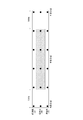
- Invention Example 2-1 as shown in FIG.
- the sodium borate aqueous solution is adhered to the range excluding the region 1000 m from both ends in the longitudinal direction of the steel strip and the region 100 mm from both ends in the width direction of the steel strip.
- an aqueous solution of sodium borate was attached to the entire surface of the steel strip.
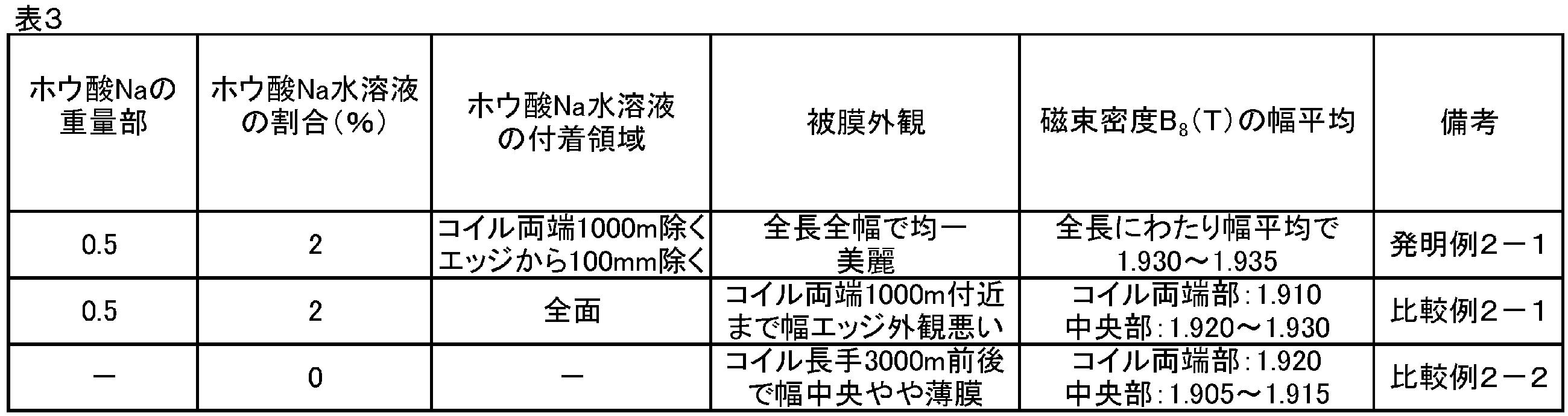
- the ratio of the amount of the aqueous solution of sodium borate attached was 2%, which was equivalent to 0.5 parts by weight.
- a roll coater was used to uniformly apply a 10 mass% magnesia slurry obtained by adding TiO 2 : 8 parts by weight to 100 parts by weight of MgO on both sides of the steel strip with an adhesion amount of 80 g / m 2. It was applied, and the aqueous solution of sodium borate was not attached by the spray nozzle.
- each steel strip was wound into a coil and annealed for 20 hours at 1200 ° C.
- the rate of temperature rise to 900 ° C. was 15 ° C./h, and the rate of temperature rise from 900 ° C. to 1200 ° C. was 10 ° C./h.
- the atmospheric gas was a mixed gas of H 2 : 75% and N 2 : 25%.
- flattening annealing was performed at 850 ° C. for 20 seconds to obtain a grain-oriented electrical steel sheet.
- Comparative Example 2-2 the film formation was insufficient in the central portion of the width in the region of 3000 m in length excluding the region of about 1000 m from both ends in the longitudinal direction of the coil, and the film was slightly thin. It was inferior in film characteristics.
- the magnetic characteristics the magnetic flux density was lowered at a position substantially corresponding to the region where the coating was slightly thin.
- Comparative Example 2-1 the coating characteristics were good at the central portion in the longitudinal direction of the coil, but the appearance of the coating deteriorated at the width edge portion from both ends in the longitudinal direction of the coil to about 1000 m, and the coil.
- the magnetic flux densities at both ends in the longitudinal direction of the coil were slightly lower than the magnetic flux densities at the central portion in the longitudinal direction of the coil.
- Invention Example 2-1 a uniform and good film appearance was obtained over the entire length and width of the coil, and the magnetic flux density was also stable at a high level.
- a grain-oriented electrical steel sheet having uniform coating characteristics and magnetic characteristics can be obtained over the entire length and / or width of the steel sheet.
Landscapes
- Chemical & Material Sciences (AREA)
- Engineering & Computer Science (AREA)
- Mechanical Engineering (AREA)
- Metallurgy (AREA)
- Organic Chemistry (AREA)
- Materials Engineering (AREA)
- Physics & Mathematics (AREA)
- Crystallography & Structural Chemistry (AREA)
- Thermal Sciences (AREA)
- Electromagnetism (AREA)
- Manufacturing & Machinery (AREA)
- Power Engineering (AREA)
- Dispersion Chemistry (AREA)
- General Chemical & Material Sciences (AREA)
- Chemical Kinetics & Catalysis (AREA)
- Manufacturing Of Steel Electrode Plates (AREA)
- Chemical Treatment Of Metals (AREA)
- Soft Magnetic Materials (AREA)
Abstract
Description
(1)所定の成分組成を有する鋼スラブに、熱間圧延を施して熱延鋼板とし、該熱延鋼板に、1回または中間焼鈍を挟む2回以上の冷間圧延を施して冷延鋼板とし、該冷延鋼板に一次再結晶焼鈍を施し、該一次再結晶焼鈍後の冷延鋼板に、液体状またはスラリー状の焼鈍分離剤を塗布した後に、鋼板をコイル状に巻き取って仕上焼鈍を施す、方向性電磁鋼板の製造方法において、
前記焼鈍分離剤を塗布する前もしくは後に、または、前記焼鈍分離剤を塗布すると同時に、前記焼鈍分離剤の成分を変更するための添加剤を、前記焼鈍分離剤と前記添加剤の合計に対して前記添加剤の重量比15%以下の範囲で添加し、前記一次再結晶焼鈍後の冷延鋼板の長手方向および/または幅方向で前記焼鈍分離剤の成分を変動させて付着させることを特徴とする方向性電磁鋼板の製造方法。
C:300ppm、Si:3.40%、Mn:0.25%、Al:50ppm、S:5ppm、Se:5ppm、N:30ppm、Cu:0.04%、及びP:0.04%を含み、残部がFeおよび不可避的不純物からなる成分組成を有する鋼スラブを、連続鋳造後、1150℃に加熱した後、熱間圧延によって2.2mm厚の熱延板とし、次いで1000℃で熱延板焼鈍を施した後、中間焼鈍を挟む2回の冷間圧延によって最終板厚が0.23mmの最終冷延板を得た。その後、840℃の湿水素雰囲気中で1分の脱炭焼鈍を行った。

次に、本発明による方向性電磁鋼板の製造方法において用いることが可能な焼鈍分離剤の塗布設備の一実施形態について説明する。
主設備としては、公知のスプレー式やロールコーター式の塗布装置を用いることができるが、焼鈍分離剤としてMgOを主体とするマグネシアスラリーを用いる場合には、供給配管内にスラッジなどが溜まりやすいので、供給配管が閉塞しやすいスプレー式よりロールコーター式の塗布装置を用いることが好ましい。この場合、主設備は、スラリー供給ノズルとスクイーズロールと、を備えることができる。スラリー供給ノズルは、鋼帯に対して、マグネシアスラリーを塗布する複数の吐出口を有する。スクイーズロールは、鋼帯を厚さ方向に挟持するとともに鋼帯に塗布されたマグネシアスラリーを所定の厚さまで均一に絞る、一対のロールを含む。ここで、スクイーズロールは、粗塗布ロールと塗布ロールとから構成することができる。ただし、マグネシアスラリーの厚さの要求精度や設置スペースの制約により、粗塗布ロールおよび塗布ロールのいずれか一方のみを設置したり、粗塗布ロールと塗布ロールとの間に、さらなるスラリー供給ノズルを設置したりすることもできる。なお、この主設備は、後述する脱炭焼鈍に用いる連続焼鈍炉の下流側であって、焼鈍分離剤を乾燥させるための乾燥炉の上流側に配置することができる。
補助設備としては、焼鈍分離剤と添加剤との混合を考慮すると、液体状の添加助剤を、噴霧量を調節しながら鋼帯に付着させることが可能なスプレー装置を用いることが好ましい。この場合、スプレー装置の噴霧量(単位面積当たりの付着重量)の好適範囲は、主設備を用いて塗布したマグネシアスラリーの単位面積当たり重量に対して15%以内となる。主設備で塗布するMgOを主体とするスラリーは、比重が大きく粘度も高いため、スプレー等で希釈液を噴霧した場合、15%を超えると焼付け乾燥までに均一に混合されないという問題が生じる。なお、噴霧量は、少ないほうが原理的には良いが、添加助剤によっては、水に溶けにくいものもあり、高濃度水溶液にしにくいものもある。液種にもよるが、10%以下がより好ましい。また、補助設備は、鋼帯の幅方向の被膜特性および磁気特性の要求精度に応じて、適宜分割して配置することができるとともに、必要に応じて鋼帯の上面側および下面側に配置することができる。なお、補助設備は、幅方向に等分に分割して配置する必要はなく、エッジと中央部とのみに配置してもよい。また、補助の水溶液が1種類ではない場合は、沈殿したり、pHが不安定となったりする場合があるので、上下流のエッジに2種類以上のスプレー装置を配置してもよい。ここで、補助設備は、主設備の上流側または下流側に、あるいは、主設備として粗塗布ロールと塗布ロールから構成されるスクイーズロールを用いる場合には、補助設備は、粗塗布ロールと塗布ロールとの間に適宜配置することができる。ただし、主設備によって塗布した焼鈍分離剤と補助設備によって付着させた添加剤とをある程度混合させる必要があるので、補助設備は、上記乾燥炉の上流側に配置する必要がある。また、主設備としてスクイーズロールを用いる場合、余剰のマグネシアスラリーは、回収および循環されて、再びスラリー供給ノズルから鋼帯に供給されるため、補助設備は、主設備の下流側に配置することが好ましい。
次に、本発明による方向性電磁鋼板の製造方法の一実施形態について説明する。なお、本発明において、方向性電磁鋼板の成分組成は、特に限定されず、公知のものを好適に用いればよい。
好適な成分組成に調整した溶鋼を、転炉、電気炉などを用いる公知の方法により精錬し、必要があれば真空処理などを施した後、通常の造塊法や連続鋳造法によりスラブを製造する。また、直接鋳造法により厚さが100mm以下の薄鋳片を直接製造してもよい。スラブは、通常の方法により加熱して、熱間圧延することができるが、鋳造後、加熱せずに直ちに熱間圧延に供してもよい。また、薄鋳片の場合には、熱間圧延を行ってもよく、熱間圧延を省略してそのまま以後の工程に供してもよい。スラブを加熱する手段は、ガス炉、誘導加熱炉、通電炉などの公知の手段を用いることができる。また、スラブの加熱に続く熱間圧延は、公知の条件で行なえばよく、特に限定されない。
次いで、必要に応じて熱延板焼鈍を行う。ゴス組織を製品板において高度に発達させるためには、熱延板焼鈍温度を800~1200℃とすることが好ましい。というのは、熱延板焼鈍温度が800℃未満では、熱間圧延でのバンド組織が残留し、整粒の一次再結晶組織を実現することが困難になる結果、二次再結晶の発達が阻害されるからである。一方で、熱延板焼鈍温度が1200℃を超えると、不可避的に混入するインヒビタ成分が固溶し、冷却時に不均一に再析出するために、整粒一次再結晶組繊を実現することが困難となり、やはり二次再結晶の発達が阻害されるからである。また、熱延板焼鈍温度が1200℃を超えると、熱延板焼鈍後の粒径が粗大化しすぎることも、整粒の一次再結晶組織を実現する上で極めて不利である。
次いで、1回または中間焼鈍を挟む2回以上の冷間圧延を施す。上記中間焼鈍は、公知の条件で行ってもよいが、均熱温度を800~1200℃とし、均熱時間を2~300秒とすることが好ましい。均熱温度が800℃未満および/または均熱時間が2秒未満では、未再結晶組織が残存して、一次再結晶で整粒組織を得ることが難しくなり、所望の二次再結晶粒が得られず、磁気特性の劣化を引き起こすおそれがある。一方で、均熱温度が1200℃超えおよび/または均熱時間を300秒超えでは、AlN、MnS、およびMnSeのオストワルド成長が進行し、二次再結晶に必要なインヒビタの抑制力が不足して、二次再結晶しなくなり、磁気特性の劣化を引き起こすおそれがある。
最終冷延後、一次再結晶焼鈍を兼ねた脱炭焼鈍を施すことにより、Cを磁気時効の起こらない50ppm以下、好ましくは30ppm以下に低減する。脱炭焼鈍は、PH2O/PH2>0.1に制御した湿潤雰囲気下、700~1000℃の温度にて行うことが好ましい。より好ましい脱炭温度は800~900℃の範囲である。また、脱炭焼鈍後に、浸珪法によってSi量を増加させる技術を併用してもよい。脱炭焼鈍の前後または同時に窒化処理を行い、AlN等の窒化物を形成させ、インヒビタとして活用するいわゆる窒化法も含まれる。この場合、インヒビタ成分を熱延のガス炉加熱で全固溶させる必要がないため、スラブ加熱温度を低くすることができる。
次いで、焼鈍分離剤を鋼板に塗布する。本発明では、焼鈍分離剤を鋼板に均一に塗布する前もしくは後に、または、焼鈍分離剤を鋼板に均一に塗布すると同時に、焼鈍分離剤の成分を変更するための添加剤を、焼鈍分離剤と添加剤の合計に対して添加剤の重量比15%以下の範囲で添加し、鋼板の長手方向および/または幅方向で焼鈍分離剤の成分を変動させて付着させることが重要である。ここで、液体状またはスラリー状の焼鈍分離剤は、フォルステライト被膜形成と二次再結晶に最適なように成分調整されたものであり、例えばMgO(マグネシア)を主体とする焼鈍分離剤が挙げられる。また、意図的にフォルステライト被膜形成を抑制して、表面酸化物のない鏡面コイルを作製する場合には、CaO(カルシア)やAl2O3(アルミナ)を主体とする焼鈍分離剤を用いることができる。添加剤は、本工程の後にコイル状に巻き取った鋼板を仕上焼鈍に供する際の焼鈍温度、焼鈍雰囲気、および鋼板間の面圧などの偏差の影響を補正するためのものであり、例えば、硫酸Mg水溶液やホウ酸Na水溶液などが挙げられる。鏡面コイルを作製する場合には、均一な被膜形成抑止のために塩化Mgなどが用いられる。なお、鋼板に付着させた添加剤は、巨視的には固溶に近い状態となっている。以下では、図2Bを参照しつつ、焼鈍分離剤としてマグネシアスラリーを用いる場合を例に、本工程の一例を具体的に説明する。
焼鈍分離剤および添加剤の乾燥、焼付けを行った後に、鋼板をコイル状に巻き取った状態で、仕上焼鈍を施すことにより二次再結晶組織を発達させるとともにフォルステライト被膜を形成する。仕上焼鈍では、二次再結晶を完了させた後に、引き続き、純化処理を行うことが必要である。なお、Si以外の元素は、磁気特性には有害であるため、可能な限り低減することが好ましい。
その後、未反応の焼鈍分離剤を除去した後に、平坦化焼鈍を行って形状を矯正することが有効である。なお、平坦化焼鈍の前または後に、鋼板表面に張力被膜を設けることにより、僅かな張力で効果的に鉄損を改善することができる。方向性電磁鋼板は、通常積層して使用され、その際に層間の導通がないことが求められる。そのため、かかる張力被膜は、絶縁材料としての機能を鋼板に付与することも可能である。なお、鋼板に別途の絶縁被膜を設けてもよい。
ヒステリシス損と渦電流損との総和である鉄損を低減する観点から、製品板厚とする最終冷間圧延以降のいずれかの工程において、磁区細分化処理を施すことが有効である。磁区細分化処理を施すことにより、二次再結晶粒の粗大化により増大した渦電流損が低減し、ゴス方位への高集積度化や高純度化によるヒステリシス損の低減とも相俟って、極めて低い鉄損を得ることができる。磁区細分化処理の方法としては、公知の耐熱型または非耐熱型の処理方法を採用することができるが、二次再結晶後の鋼板表面に電子ビームまたはレーザービームを照射する方法であれば、鋼板の板厚内部まで磁区細分化効果を浸透させることができるので、エッチング法などの他の磁区細分化処理方法よりも優れた鉄損特性を得ることができる。
C:500ppm、Si:3.30%、Mn:0.30%、Al:180ppm、S:15ppm、Se:100ppm、N:90ppm、P:0.06%、Sb:0.07%、及びMo:0.015%を含み、残部がFeおよび不可避的不純物の成分組成からなる鋼スラブを、1350℃に加熱した後、熱間圧延して2.2mm厚とした後、1050℃で30秒の熱延板焼鈍を施し、タンデムミルにて1回の冷間圧延により最終板厚0.23mmの冷延板とした。その後、冷延板を820℃まで加熱し、湿水素雰囲気中にて1.5分の脱炭焼鈍を行った。

C:600ppm、Si:3.40%、Mn:0.15%、Al:300ppm、S:70ppm、Cr:0.12%、N:90ppm、P:0.02%、及びSn:0.05%を含み、残部がFeおよび不可避的不純物からなる成分組成の鋼スラブを、1150℃に加熱した後、熱間圧延して2.2mm厚とした後、1100℃で30秒の熱延板焼鈍を施し、900℃までを10℃/秒で冷却して900℃で短時間保持した後、急冷した。次いで、酸洗後にゼンジミアミルにて最終板厚0.23mmの冷延板とした。その後、820℃まで加熱し、湿水素雰囲気中で2分の脱炭焼鈍と、750℃で30秒のアンモニアガスを含む窒化焼鈍を行った。
2 塗布ロール
3 スプレー装置
4 粗塗布ロール
5 スラリー供給ノズル
Claims (2)
- 所定の成分組成を有する鋼スラブに、熱間圧延を施して熱延鋼板とし、該熱延鋼板に、1回または中間焼鈍を挟む2回以上の冷間圧延を施して冷延鋼板とし、該冷延鋼板に一次再結晶焼鈍を施し、該一次再結晶焼鈍後の冷延鋼板に、液体状またはスラリー状の焼鈍分離剤を塗布した後に、鋼板をコイル状に巻き取って仕上焼鈍を施す、方向性電磁鋼板の製造方法において、
前記焼鈍分離剤を塗布する前もしくは後に、または、前記焼鈍分離剤を塗布すると同時に、前記焼鈍分離剤の成分を変更するための添加剤を、前記焼鈍分離剤と前記添加剤の合計に対して前記添加剤の重量比15%以下の範囲で添加し、前記一次再結晶焼鈍後の冷延鋼板の長手方向および/または幅方向で前記焼鈍分離剤の成分を変動させて付着させることを特徴とする方向性電磁鋼板の製造方法。 - 液体状またはスラリー状の焼鈍分離剤を鋼板に塗布するための主設備と、前記焼鈍分離剤の成分を変更するための添加剤を、前記焼鈍分離剤と前記添加剤の合計に対して前記添加剤の重量比15%以下の範囲で添加し、前記鋼板の長手方向および/または幅方向で前記焼鈍分離剤の成分を変動させて付着させるための補助設備と、を備えることを特徴とする焼鈍分離剤の塗布設備。
Priority Applications (4)
| Application Number | Priority Date | Filing Date | Title |
|---|---|---|---|
| KR1020217033024A KR102575805B1 (ko) | 2019-03-26 | 2020-03-26 | 방향성 전기 강판의 제조 방법 및 어닐링 분리제의 도포 설비 |
| CN202080024161.8A CN113631737A (zh) | 2019-03-26 | 2020-03-26 | 方向性电磁钢板的制造方法和退火分离剂的涂布设备 |
| JP2020542024A JP7151773B2 (ja) | 2019-03-26 | 2020-03-26 | 方向性電磁鋼板の製造方法および焼鈍分離剤の塗布設備 |
| US17/593,560 US12467106B2 (en) | 2019-03-26 | 2020-03-26 | Method of producing grain-oriented electrical steel sheet and annealing separator application line |
Applications Claiming Priority (2)
| Application Number | Priority Date | Filing Date | Title |
|---|---|---|---|
| JP2019-059316 | 2019-03-26 | ||
| JP2019059316 | 2019-03-26 |
Publications (1)
| Publication Number | Publication Date |
|---|---|
| WO2020196773A1 true WO2020196773A1 (ja) | 2020-10-01 |
Family
ID=72611536
Family Applications (1)
| Application Number | Title | Priority Date | Filing Date |
|---|---|---|---|
| PCT/JP2020/013750 Ceased WO2020196773A1 (ja) | 2019-03-26 | 2020-03-26 | 方向性電磁鋼板の製造方法および焼鈍分離剤の塗布設備 |
Country Status (5)
| Country | Link |
|---|---|
| US (1) | US12467106B2 (ja) |
| JP (1) | JP7151773B2 (ja) |
| KR (1) | KR102575805B1 (ja) |
| CN (1) | CN113631737A (ja) |
| WO (1) | WO2020196773A1 (ja) |
Cited By (1)
| Publication number | Priority date | Publication date | Assignee | Title |
|---|---|---|---|---|
| JP2022163524A (ja) * | 2021-04-14 | 2022-10-26 | Jfeスチール株式会社 | 液体またはスラリーの塗布装置、液体またはスラリーの塗布方法および塗装金属帯の製造方法 |
Families Citing this family (3)
| Publication number | Priority date | Publication date | Assignee | Title |
|---|---|---|---|---|
| CN115478135B (zh) * | 2022-09-06 | 2024-02-02 | 东北大学 | 一种具有强{100}取向柱状晶的高硅钢薄带的制备方法 |
| CN116083701B (zh) * | 2023-04-06 | 2023-07-28 | 首钢智新迁安电磁材料有限公司 | 一种表面优良的高磁感取向硅钢及其制备方法 |
| CN116516133B (zh) * | 2023-04-13 | 2023-12-01 | 首钢智新迁安电磁材料有限公司 | 一种晶粒组织和磁性能均匀的取向硅钢及其制备方法 |
Citations (2)
| Publication number | Priority date | Publication date | Assignee | Title |
|---|---|---|---|---|
| JPH09241754A (ja) * | 1996-03-04 | 1997-09-16 | Kawasaki Steel Corp | 方向性けい素鋼板の製造方法および焼鈍分離剤塗布装置 |
| JPH11350152A (ja) * | 1998-06-05 | 1999-12-21 | Nippon Steel Corp | 鋼板への液体もしくはスラリーの均一塗布方法 |
Family Cites Families (11)
| Publication number | Priority date | Publication date | Assignee | Title |
|---|---|---|---|---|
| DE2412046A1 (de) * | 1974-03-13 | 1975-09-25 | Korel Korrosionsschutz Elektro | Bauteil mit mehreren elektrisch leitenden metallischen und nichtmetallischen flammgespritzten flaechenleitern |
| US4655854A (en) * | 1983-10-27 | 1987-04-07 | Kawasaki Steel Corporation | Grain-oriented silicon steel sheet having a low iron loss free from deterioration due to stress-relief annealing and a method of producing the same |
| JPS6267118A (ja) | 1985-09-18 | 1987-03-26 | Kawasaki Steel Corp | 電磁鋼板への焼鈍分離剤の塗布方法および装置 |
| JPH0668133B2 (ja) * | 1987-05-11 | 1994-08-31 | 川崎製鉄株式会社 | 磁気特性に優れた一方向性けい素鋼板の製造方法 |
| JPH0531425A (ja) * | 1991-07-30 | 1993-02-09 | Kawasaki Steel Corp | 焼鈍分離剤の塗布装置 |
| JPH05104036A (ja) | 1991-10-16 | 1993-04-27 | Kawasaki Steel Corp | 焼鈍分離剤の塗布装置 |
| JP3463403B2 (ja) | 1995-04-13 | 2003-11-05 | Jfeスチール株式会社 | 方向性珪素鋼板の製造方法および焼鈍分離剤塗布装置 |
| JP4501655B2 (ja) * | 2004-11-29 | 2010-07-14 | Jfeスチール株式会社 | 方向性電磁鋼板の製造方法 |
| KR100762436B1 (ko) * | 2006-10-18 | 2007-10-02 | 주식회사 포스코 | 표면성상이 우수한 방향성 전기강판용 소둔분리제 및 이를이용한 방향성 전기강판의 제조방법 |
| JP5831435B2 (ja) | 2012-12-11 | 2015-12-09 | Jfeスチール株式会社 | 磁気特性に優れた方向性電磁鋼板の製造方法 |
| JP6028933B2 (ja) * | 2013-10-31 | 2016-11-24 | Jfeスチール株式会社 | 方向性電磁鋼板の製造方法 |
-
2020
- 2020-03-26 JP JP2020542024A patent/JP7151773B2/ja active Active
- 2020-03-26 WO PCT/JP2020/013750 patent/WO2020196773A1/ja not_active Ceased
- 2020-03-26 KR KR1020217033024A patent/KR102575805B1/ko active Active
- 2020-03-26 US US17/593,560 patent/US12467106B2/en active Active
- 2020-03-26 CN CN202080024161.8A patent/CN113631737A/zh active Pending
Patent Citations (2)
| Publication number | Priority date | Publication date | Assignee | Title |
|---|---|---|---|---|
| JPH09241754A (ja) * | 1996-03-04 | 1997-09-16 | Kawasaki Steel Corp | 方向性けい素鋼板の製造方法および焼鈍分離剤塗布装置 |
| JPH11350152A (ja) * | 1998-06-05 | 1999-12-21 | Nippon Steel Corp | 鋼板への液体もしくはスラリーの均一塗布方法 |
Cited By (2)
| Publication number | Priority date | Publication date | Assignee | Title |
|---|---|---|---|---|
| JP2022163524A (ja) * | 2021-04-14 | 2022-10-26 | Jfeスチール株式会社 | 液体またはスラリーの塗布装置、液体またはスラリーの塗布方法および塗装金属帯の製造方法 |
| JP7384188B2 (ja) | 2021-04-14 | 2023-11-21 | Jfeスチール株式会社 | 液体またはスラリーの塗布装置、液体またはスラリーの塗布方法および塗装金属帯の製造方法 |
Also Published As
| Publication number | Publication date |
|---|---|
| US20220195553A1 (en) | 2022-06-23 |
| JPWO2020196773A1 (ja) | 2021-04-30 |
| KR20210136119A (ko) | 2021-11-16 |
| US12467106B2 (en) | 2025-11-11 |
| KR102575805B1 (ko) | 2023-09-06 |
| JP7151773B2 (ja) | 2022-10-12 |
| CN113631737A (zh) | 2021-11-09 |
Similar Documents
| Publication | Publication Date | Title |
|---|---|---|
| EP1992708B1 (en) | Process for producing grain-oriented magnetic steel sheet with excellent magnetic property | |
| CN103069032B (zh) | 方向性电磁钢板及其制造方法 | |
| JP5417936B2 (ja) | 方向性電磁鋼板の製造方法 | |
| JP5772410B2 (ja) | 方向性電磁鋼板の製造方法 | |
| CN102906283B (zh) | 单向性电磁钢板的制造方法 | |
| CN103097563A (zh) | 方向性电磁钢板及其制造方法 | |
| JP7151773B2 (ja) | 方向性電磁鋼板の製造方法および焼鈍分離剤の塗布設備 | |
| RU2497956C1 (ru) | Способ изготовления листа из электротехнической стали с ориентированной зеренной структурой | |
| JP2006152387A (ja) | 磁気特性に優れた方向性電磁鋼板 | |
| WO2012001952A1 (ja) | 方向性電磁鋼板およびその製造方法 | |
| JP2003096520A (ja) | 皮膜特性と高磁場鉄損に優れる高磁束密度一方向性電磁鋼板の製造方法 | |
| KR102579758B1 (ko) | 방향성 전자 강판의 제조 방법 | |
| KR20190071745A (ko) | 전자 강판 제조용의 열연 강판 및 그의 제조 방법 | |
| WO2020149337A1 (ja) | 方向性電磁鋼板の製造方法 | |
| RU2471877C1 (ru) | Способ обработки стали для листа электротехнической стали с ориентированной зеренной структурой и способ получения листа электротехнической стали с ориентированной зеренной структурой | |
| WO2020149336A1 (ja) | 方向性電磁鋼板の製造方法 | |
| JP5434524B2 (ja) | 方向性電磁鋼板の製造方法 | |
| EP4474492A1 (en) | Method for producing grain-oriented electromagnetic steel sheet | |
| WO2020149351A1 (ja) | 方向性電磁鋼板の製造方法 | |
| JP7816665B1 (ja) | 方向性電磁鋼板の製造方法 | |
| JP7816664B1 (ja) | 方向性電磁鋼板の製造方法 | |
| KR20210110868A (ko) | 일 방향성 전자 강판의 제조 방법 | |
| WO2020149326A1 (ja) | 方向性電磁鋼板の製造方法 | |
| JP2011111653A (ja) | 方向性電磁鋼板の製造方法 | |
| EP4159337A1 (en) | Method for manufacturing grain-oriented electromagnetic steel sheet, and equipment line |
Legal Events
| Date | Code | Title | Description |
|---|---|---|---|
| ENP | Entry into the national phase |
Ref document number: 2020542024 Country of ref document: JP Kind code of ref document: A |
|
| 121 | Ep: the epo has been informed by wipo that ep was designated in this application |
Ref document number: 20778236 Country of ref document: EP Kind code of ref document: A1 |
|
| NENP | Non-entry into the national phase |
Ref country code: DE |
|
| ENP | Entry into the national phase |
Ref document number: 20217033024 Country of ref document: KR Kind code of ref document: A |
|
| 122 | Ep: pct application non-entry in european phase |
Ref document number: 20778236 Country of ref document: EP Kind code of ref document: A1 |
|
| WWG | Wipo information: grant in national office |
Ref document number: 17593560 Country of ref document: US |