WO2020196576A1 - 電装品箱 - Google Patents
電装品箱 Download PDFInfo
- Publication number
- WO2020196576A1 WO2020196576A1 PCT/JP2020/013191 JP2020013191W WO2020196576A1 WO 2020196576 A1 WO2020196576 A1 WO 2020196576A1 JP 2020013191 W JP2020013191 W JP 2020013191W WO 2020196576 A1 WO2020196576 A1 WO 2020196576A1
- Authority
- WO
- WIPO (PCT)
- Prior art keywords
- electrical component
- air
- component box
- cooler
- suction
- Prior art date
- Legal status (The legal status is an assumption and is not a legal conclusion. Google has not performed a legal analysis and makes no representation as to the accuracy of the status listed.)
- Ceased
Links
Images






Classifications
-
- F—MECHANICAL ENGINEERING; LIGHTING; HEATING; WEAPONS; BLASTING
- F24—HEATING; RANGES; VENTILATING
- F24F—AIR-CONDITIONING; AIR-HUMIDIFICATION; VENTILATION; USE OF AIR CURRENTS FOR SCREENING
- F24F11/00—Control or safety arrangements
- F24F11/30—Control or safety arrangements for purposes related to the operation of the system, e.g. for safety or monitoring
- F24F11/46—Improving electric energy efficiency or saving
-
- H—ELECTRICITY
- H05—ELECTRIC TECHNIQUES NOT OTHERWISE PROVIDED FOR
- H05K—PRINTED CIRCUITS; CASINGS OR CONSTRUCTIONAL DETAILS OF ELECTRIC APPARATUS; MANUFACTURE OF ASSEMBLAGES OF ELECTRICAL COMPONENTS
- H05K7/00—Constructional details common to different types of electric apparatus
- H05K7/20—Modifications to facilitate cooling, ventilating, or heating
- H05K7/20009—Modifications to facilitate cooling, ventilating, or heating using a gaseous coolant in electronic enclosures
- H05K7/20136—Forced ventilation, e.g. by fans
- H05K7/20145—Means for directing air flow, e.g. ducts, deflectors, plenum or guides
-
- F—MECHANICAL ENGINEERING; LIGHTING; HEATING; WEAPONS; BLASTING
- F24—HEATING; RANGES; VENTILATING
- F24F—AIR-CONDITIONING; AIR-HUMIDIFICATION; VENTILATION; USE OF AIR CURRENTS FOR SCREENING
- F24F1/00—Room units for air-conditioning, e.g. separate or self-contained units or units receiving primary air from a central station
- F24F1/06—Separate outdoor units, e.g. outdoor unit to be linked to a separate room comprising a compressor and a heat exchanger
- F24F1/20—Electric components for separate outdoor units
- F24F1/24—Cooling of electric components
-
- H—ELECTRICITY
- H05—ELECTRIC TECHNIQUES NOT OTHERWISE PROVIDED FOR
- H05K—PRINTED CIRCUITS; CASINGS OR CONSTRUCTIONAL DETAILS OF ELECTRIC APPARATUS; MANUFACTURE OF ASSEMBLAGES OF ELECTRICAL COMPONENTS
- H05K7/00—Constructional details common to different types of electric apparatus
- H05K7/20—Modifications to facilitate cooling, ventilating, or heating
- H05K7/20009—Modifications to facilitate cooling, ventilating, or heating using a gaseous coolant in electronic enclosures
- H05K7/20136—Forced ventilation, e.g. by fans
- H05K7/20181—Filters; Louvers
-
- H—ELECTRICITY
- H05—ELECTRIC TECHNIQUES NOT OTHERWISE PROVIDED FOR
- H05K—PRINTED CIRCUITS; CASINGS OR CONSTRUCTIONAL DETAILS OF ELECTRIC APPARATUS; MANUFACTURE OF ASSEMBLAGES OF ELECTRICAL COMPONENTS
- H05K7/00—Constructional details common to different types of electric apparatus
- H05K7/20—Modifications to facilitate cooling, ventilating, or heating
- H05K7/20009—Modifications to facilitate cooling, ventilating, or heating using a gaseous coolant in electronic enclosures
- H05K7/202—Air circulating in closed loop within enclosure wherein heat is removed through heat-exchangers
-
- H—ELECTRICITY
- H05—ELECTRIC TECHNIQUES NOT OTHERWISE PROVIDED FOR
- H05K—PRINTED CIRCUITS; CASINGS OR CONSTRUCTIONAL DETAILS OF ELECTRIC APPARATUS; MANUFACTURE OF ASSEMBLAGES OF ELECTRICAL COMPONENTS
- H05K7/00—Constructional details common to different types of electric apparatus
- H05K7/20—Modifications to facilitate cooling, ventilating, or heating
- H05K7/20218—Modifications to facilitate cooling, ventilating, or heating using a liquid coolant without phase change in electronic enclosures
- H05K7/20272—Accessories for moving fluid, for expanding fluid, for connecting fluid conduits, for distributing fluid, for removing gas or for preventing leakage, e.g. pumps, tanks or manifolds
-
- F—MECHANICAL ENGINEERING; LIGHTING; HEATING; WEAPONS; BLASTING
- F24—HEATING; RANGES; VENTILATING
- F24F—AIR-CONDITIONING; AIR-HUMIDIFICATION; VENTILATION; USE OF AIR CURRENTS FOR SCREENING
- F24F1/00—Room units for air-conditioning, e.g. separate or self-contained units or units receiving primary air from a central station
- F24F1/06—Separate outdoor units, e.g. outdoor unit to be linked to a separate room comprising a compressor and a heat exchanger
- F24F1/26—Refrigerant piping
- F24F1/30—Refrigerant piping for use inside the separate outdoor units
Definitions
- This disclosure relates to an electrical component box mounted on an outdoor unit of an air conditioner.
- the outdoor unit of an air conditioner is usually equipped with an electrical component box containing electronic components that control the operation of the outdoor unit.
- an electrical component box containing electronic components that control the operation of the outdoor unit.
- Patent Document 1 provides a suction port for sucking cooling air on a side wall portion of an electrical component box, and a discharge port on a side wall portion facing the suction port.
- the electrical component box is a closed space, and a cooling means is provided inside so that the air in the closed space is naturally circulated while being cooled.
- Patent Document 1 has a problem that the cooling capacity is insufficient when it is used in an area where the outside air temperature is high because the inside of the electrical component box is cooled by outdoor air. Further, the one described in Patent Document 2 has a problem that the structure of the electrical component box becomes complicated and the size becomes large because the cooling means is provided inside the electrical component box.
- An object of the present disclosure is to provide an electrical component box mounted on an outdoor unit of an air conditioner whose structure can be simplified and which can be used in an area where the outside air temperature is high.
- the air sucked from the suction port is cooled and then supplied to the electronic component storage unit, so that the electronic component can be cooled even in an area where the outside air temperature is high, and the electrical component box can be cooled.
- the structure can also be simplified.
- the suction ventilation passage for guiding the air sucked from the suction port to the electronic component storage portion is further provided, and the cooler provides air in the suction ventilation passage. It is configured to cool.
- the cooler is configured to cool the air sucked from the suction port in the suction ventilation passage, so that the electrical component box can be made a simple configuration.
- the suction ventilation passage has at least one turning portion for changing the ventilation direction.
- the dust, dust, rainwater, seawater, etc. contained in the air sucked from the suction port can be separated at the turning part, and the electronic parts storage part such as dust, dust, rainwater, seawater, etc. can be separated. Invasion deposition can be reduced.
- the cooler has a heat sink that is cooled to a temperature lower than the air outside the electrical component box, and the heat sink is at least one of the turning portions.
- the heat sink is formed on the base portion that changes the ventilation direction at the turning portion, the cold heat source portion attached to the base portion, and the surface of the base portion that faces the suction ventilation path. It has a fin portion that has been formed.
- the dust, dust, rainwater, seawater, etc. contained in the air sucked from the suction port can be separated at the turning part, and the electronic parts storage part such as dust, dust, rainwater, seawater, etc. can be separated. Invasion deposition can be further reduced. Therefore, it is suitable as an electrical component box in an air conditioner for a dusty area where the outside air temperature is high.
- the cooler includes a filter unit for removing dust contained in the air.
- the dust contained in the air can be removed by the filter unit, so that the invasion and accumulation of the dust in the electronic component storage unit can be further reduced.
- dust, rainwater, seawater and the like contained in the air can also be removed by the filter unit.
- the filter portion is made of flocked hair formed on the surface for cooling the passing air in the cooler.
- the filter portion is formed in the place where the ventilation hits, dust, dust, rainwater, seawater, etc. can be effectively removed. Further, the dust, dust, rainwater, seawater and the like adhering to the surface for cooling the passing air in the cooler can be washed away with the condensed water generated by the cooler.
- the flocking is formed only on the surface for cooling the passing air in the cooler on the upstream side of the air flow.
- the cooler is configured to cool at least a part of the wall body forming the suction ventilation path.
- the cooler can be made a simpler configuration.
- the electrical component box is provided with a drain discharge port for discharging condensed water generated when air is cooled by the cooler.
- the condensed water generated in the cooler can be discharged.
- the re-scattering of condensed water can be suppressed.
- dust, dust, rainwater, seawater, etc. in the air are removed by the cooler, these can be washed away with dew condensation water and discharged together with the dew condensation water.
- FIG. 3 is a cross-sectional view of a lower portion of an electrical component box according to a third embodiment.
- FIG. 1 is an outdoor unit 2 of an air conditioner that houses an electrical component box 1.
- One or a plurality of indoor units are connected to the outdoor unit 2.
- the illustration and description of the indoor unit will be omitted.
- the front-back, left-right, and up-down directions are the directions shown in FIG.
- the white arrows and the solid arrows indicate the air flow direction in the electrical component box 1.
- the outdoor unit 2 includes a compressor, an outdoor heat exchanger 3 that exchanges heat with air, an outdoor blower 4 that circulates air to the outdoor heat exchanger 3, and the like. It is stored.
- the outdoor unit 2 is configured as an outdoor unit of a heat pump type air conditioner.
- the compressor is arranged in an atmosphere in which the air passing through the outdoor heat exchanger 3 flows.
- the outdoor heat exchanger 3 is arranged along the inside of the air intake port on the back surface, the right side surface, and the rear portion of the left side surface.
- the outdoor blower 4 is, for example, an axial blower (so-called propeller blower).
- the outdoor blower 4 is arranged so as to take in air from each air suction port on the back surface, side surface, etc., and exhaust the air from the upper surface.
- the electronic component storage unit 10 stores the electronic component 11 that controls the operation of the outdoor unit 2.
- the electronic component storage unit 10 is located above the electrical component box 1 except for the lower portion, and occupies most of the electrical component box 1.
- the electronic component storage unit 10 includes a contact port 12 for taking in air for cooling the electronic component 11, and an discharge port 13 for discharging air in the electrical component box 1.
- the contact port 12 is formed on the bottom surface of the electronic component storage unit 10.
- the discharge port 13 is formed at an upper portion of the back surface of the electronic component storage unit 10 so as to be closer to the suction side of the outdoor blower 4.
- the suction ventilation passage 20 is provided with a horizontal partition plate 21 that divides the inside into upper and lower halves at an intermediate position in the vertical direction.
- the suction ventilation passage 20 is provided with a suction port 22 for sucking the air in the outdoor unit 2 on the right side of the lower portion of the horizontal partition plate 21. Air that has passed through the outdoor heat exchanger 3 circulates in the outdoor unit 2.
- the suction ventilation passage 20 constitutes a ventilation passage that guides the air sucked from the suction port 22 to the communication port 12 of the electronic component storage unit 10.
- the lower portion of the horizontal partition plate 21 is the lower passage portion 23, and the upper portion of the horizontal partition plate 21 is the upper passage portion 24.
- the lower passage portion 23 and the upper passage portion 24 are configured to communicate in a U shape on the left side of the horizontal partition plate 21.
- the upper passage portion 24 of the suction ventilation passage 20 is configured to communicate with the electronic component storage portion 10 on the right side.
- the air in the outdoor unit 2 sucked from the suction port 22 is conveyed to the left side by the lower passage portion 23, changes the ventilation direction 180 degrees upward in the left side portion, and moves to the right side in the upper passage portion 24. Be transported.
- the conversion portion in the ventilation direction on the left side portion of the suction ventilation passage 20 is referred to as the first conversion portion 25.
- the air conveyed through the upper passage portion 24 changes the ventilation direction by 90 degrees on the right side portion and is introduced into the electronic component storage portion 10 via the communication port 12.
- the conversion portion in the ventilation direction on the right side portion of the upper passage portion 24 is referred to as the second conversion portion 26. Therefore, in the present embodiment, the suction ventilation passage 20 from the suction port 22 to the electronic component storage portion 10 includes two turning portions 25 and 26.
- the cold heat source unit 31 circulates a refrigerant as a cold heat source to exchange heat with the base 33, and cools the heat sink 32 so as to be lower than the external temperature of the electrical component box 1.
- the cold heat source unit 31 in this embodiment is composed of a refrigerant pipe.
- the heat sink 32 is made of a material having good heat transfer performance such as aluminum and copper, and is composed of a base portion 33 and a fin portion 34. The heat sink 32 is inserted and fixed to the turning portion 25 from the outside in an opening formed on the left side surface of the suction ventilation passage 20.
- the fin portion 34 exchanges heat with air that changes direction by 180 degrees from the lower passage portion 23 of the suction ventilation passage 20 to the upper passage portion 24.
- a thick plate-shaped base portion 33 on the left side side and a fin portion 34 on the right side side are integrated.
- the fin portion 34 includes a plurality of groove-shaped portions 34a and a plurality of fins 34b.
- the air flowing from the lower passage portion 23 of the suction ventilation passage 20 to the turning portion 25 enters the groove-shaped portion 34a and enters the surface of the fin 34b and the front surface of the base 33 (that is, the bottom surface of the groove-shaped portion 34a).
- the ventilation direction is changed by 180 degrees while being cooled by heat exchange.
- the electronic component 11 that controls the operation of the air conditioner which is housed in the electrical component box 1, generates heat as the air conditioner operates.
- the power device constituting the inverter device as the drive circuit of the compressor has a large amount of heat generation.
- the air conditioner operates, the air after passing through the outdoor heat exchanger 3 circulates around the electrical component box 1. This air contains dust, dust, rainwater, seawater and the like. Further, a low-temperature refrigerant is circulated in the refrigerant pipes constituting the cold heat source unit 31. Along with this, the fin portion 34 of the cooler 30 is controlled to a predetermined temperature.
- the discharge port 13 of the electrical component box 1 is closer to the suction side of the outdoor blower 4 than the suction port 22, the pressure near the discharge port 13 of the electrical component box 1 is lower than the pressure near the suction port 22. As a result, the air in the electrical component box 1 is discharged, and the air around the electrical component box 1 is sucked in from the suction port 22 as air for cooling the electronic component 11.
- the air sucked from the suction port 22 is guided to the first turning portion 25 by the lower passage portion 23 of the suction ventilation passage 20. Then, since the air guided to the turning portion 25 is changed in the ventilation direction by 180 degrees upward at the turning portion 25, the dust, dust, rainwater, seawater and the like contained in the air are separated by centrifugal force. Further, the air guided to the turning portion 25 is cooled and dehumidified on the surface of the heat sink 32 of the cooler 30, and flows to the second turning portion 26. The air is further removed by centrifugal force from the dust, dust, rainwater, seawater, etc. remaining in the air at the turning portion 26, and is introduced into the electronic component storage portion 10 via the communication port 12.
- the air introduced into the electronic component storage section 10 is discharged from the discharge port 13 to the suction side of the outdoor blower 4 after sufficiently cooling the electronic component 11 in the electronic component storage section 10.
- the discharged air is sucked into the outdoor blower 4 and discharged to the outside of the outdoor unit 2.
- the cooler 30 Since the cooler 30 is configured to cool the air supplied to the electronic component storage unit 10 in the suction ventilation passage 20, the cooler 30 can be configured in a simple manner.
- Dust, dust, rainwater, seawater, etc. contained in the air supplied to the electronic component storage section 10 can be separated by the first turning section 25 and the second turning section 26, and the dust, dust, etc. can be separated.
- Rainwater, seawater, etc. can be reduced from entering and accumulating in the electronic component storage portion 10. Therefore, it is suitable as an electrical component box 1 in an air conditioner for an area where the outside air temperature is high and there is a lot of dust.
- the former is the main separation of dust, dust, rainwater, seawater, etc. in the first conversion portion 25 and the second conversion portion 26, and the latter is auxiliary.
- the fin portion 34 of the heat sink 32 of the cooler 30 is provided with a filter portion 40 for removing dust, dust, rainwater, seawater, etc. contained in the air that cools the electronic component 11. It is provided so that the condensed water generated by the heat sink 32 can be discharged.
- the heat sink 32 of the cooler 30 provided in the electrical component box 1 according to the second embodiment is formed by applying resin flocking 41 to the surface of the lower half of the fin portion 34 to form the filter portion 40. are doing. Further, below the heat sink 32, a pool portion 50 for collecting the condensed water generated by the heat sink 32 and dripping downward is formed on the bottom wall of the lower passage portion 23. Further, a drain discharge port 51 is provided at the lowermost portion of the pool portion 50.
- the electrical component box 1 according to the second embodiment has the same action and effect as the electrical component box 1 according to the first embodiment, and can also exert the following effects.
- the electrical component box 1 according to the third embodiment has a pre-filter 42 that deforms the pool portion 50 in the electrical component box 1 according to the second embodiment and further removes dust contained in the air sucked from the suction port 22. It is provided.
- the pool portion 50 provided in the electrical component box 1 according to the third embodiment is assumed that substantially the entire bottom wall of the lower passage portion 23 is inclined downward toward the right side.
- a drain discharge port 51 is provided on the right side portion, which is the lowermost portion of the pool portion 50.
- a pre-filter 42 is detachably provided at the suction port 22.
- the pre-filter 42 may be like a fiber material generally used for the indoor air suction port of an air conditioner fixed in a frame.
- the electrical component box 1 according to the third embodiment has the same action and effect as the electrical component box 1 according to the second embodiment, and can also exert the following effects.
- the electrical component box 1 according to the fourth embodiment is a modification of the fin portion 34 of the heat sink 32 of the cooler 30 in the electrical component box 1 according to the first embodiment.
- the heat sink 32 of the cooler 30 provided in the electrical component box 1 according to the fourth embodiment has fins 34b in the first embodiment as pin fins. is there.
- the electrical component box 1 according to the fourth embodiment has the same action and effect as the electrical component box 1 according to the second embodiment, and can also exert the following effects.
- the fin section 34 collects dust, dirt, rainwater, seawater, etc. contained in the air. Can be removed.
- the electrical component box 1 according to the fifth embodiment is a modification of the filter portion 40 provided on the fin portion 34 of the heat sink 32 in the electrical component box 1 according to the second embodiment.
- the filter unit 40 according to the fifth embodiment is filled with the metal fiber 43 into the groove-shaped portion 34a between the fins 34b instead of the flocked 41 as the filter unit 40 in the second embodiment. This is the filter unit 40.
- the electrical component box 1 according to the fifth embodiment has the same action and effect as the electrical component box 1 according to the second embodiment, and can also exert the following effects.
- the electrical component box 1 according to the sixth embodiment is a modification of the configurations of the suction ventilation passage 20 and the cooler 30 in the first embodiment.
- the electrical component box 1 according to the sixth embodiment has the same action and effect as the electrical component box 1 according to the first embodiment, and can also exert the following effects.
- the configuration of the cooler 30 and the suction ventilation passage 20 is simplified.
- the cold heat source unit 31 may have a simple structure as long as it cools the outer surface of at least a part of the suction ventilation passage 20.
- the electrical component box 1 according to the first embodiment integrally forms the electronic component storage portion 10 and the suction ventilation passage 20, but the electrical component box 1 according to the seventh embodiment is separable and can be separated. , It is made to be able to be manufactured separately.
- the partition wall between the electronic component storage section 10 containing the electronic component 11 and the suction ventilation passage 20 is the bottom surface of the electronic component storage section 10. Therefore, the electronic component storage unit 10 is formed as an independent housing that forms a closed space by itself.
- the suction ventilation passage 20 has no upper surface wall and is manufactured with the same structure as that of the first embodiment.
- a pipe as a cold heat source unit 31 is attached and shown, but the cold heat source unit 31 is after assembling the suction ventilation passage 20 and the electronic component storage portion 10, or the suction ventilation passage 20. Is attached when assembling to the electronic component storage unit 10. Therefore, the suction ventilation passage 20 may be manufactured in a state where the cold heat source portion 31 is not attached.
- the heat sink 32 constituting the cooler 30 may be assembled after the housing of the suction ventilation passage 20 is completed. Further, the heat sink 32 constituting the cooler 30 may be incorporated into the suction ventilation passage 20 before or after the assembly of the housing of the suction ventilation passage 20 into the electronic component storage portion 10.
- the electrical component box 1 according to the eighth embodiment is the one in which the suction ventilation passage 20 is omitted in the first embodiment.
- the cooler 30 is attached below the contact port 12 of the electronic component storage unit 10.
- the cooler 30 is basically a symmetrical configuration of the cooler 30 in the first embodiment.
- the cold heat source unit 31 and the heat sink 32 are the same as those in the first embodiment.
- the opening position and opening size of the contact port 12 and the plane position and plane size of the fin portion 34 are substantially the same.
- a closing plate 36 that closes the lower surface of the groove-shaped portion 34a of the fin portion 34 is attached to the lower surface of the heat sink 32.
- the air in the outdoor unit 2 is sucked into the electronic component storage unit 10 while changing the ventilation direction from the left side of the heat sink 32 toward the communication port 12.
- the conversion angle in the ventilation direction is 45 degrees or more.
- the heat sink 32 forms a first turning portion 25 that removes dust, dust, rainwater, seawater, and the like by changing the ventilation direction by 45 degrees or more.
- the electrical component box 1 according to the eighth embodiment has the same action and effect as the electrical component box 1 according to the first embodiment, and can also exert the following effects.
- the electrical component box 1 according to the ninth embodiment is a modification of the configurations of the suction ventilation passage 20 and the cooler 30.
- the electronic component storage unit 10 according to the ninth embodiment is the same as that of the first embodiment.
- the suction ventilation passage 20 according to the ninth embodiment the horizontal partition plate 21 is abolished, a suction port 22 is provided on the left side, and the air in the outdoor unit 2 sucked from the suction port 22 on the left side is contacted on the right side. It is designed to guide linearly to the front of 12.
- the air flowing through the suction ventilation passage 20 is introduced into the electronic component storage portion 10 via the communication port 12 by changing the ventilation direction by 90 degrees on the right side portion. Therefore, the right side portion of the suction ventilation passage 20 constitutes a first turning portion 25 that removes dust, dust, rainwater, seawater, etc. by changing the ventilation direction by 90 degrees.
- the cooler 30 in this embodiment includes a cold heat source portion 31 composed of a refrigerant pipe for circulating a low temperature refrigerant and a heat sink 32 composed of only a thick plate-shaped portion.
- the cold heat source unit 31 in the present embodiment corresponds to the cold heat source unit 31 in the first embodiment
- the heat sink 32 in the present embodiment corresponds to a configuration including only the base 33 of the heat sink 32 in the first embodiment.
- the heat sink 32 in this embodiment is attached in close contact with the bottom surface of the suction ventilation passage 20.
- the electrical component box 1 according to the ninth embodiment has the same action and effect as the electrical component box 1 according to the first embodiment, and can also exert the following effects.
- suction ventilation passage 20 does not need to have two upper and lower layers, it is simplified and downsized. Further, the heat sink 32 also needs only a plate-shaped member, which is simplified.
- the outdoor unit 2 according to the tenth embodiment is a modification of the configuration of the electrical component box 1 so that the outside air is directly sucked into the suction port 22 of the electrical component box 1.
- the electrical component box 1 is arranged in front of the outdoor heat exchanger 3 so as to be along the left side surface of the outdoor unit 2 as in the first embodiment. ..
- the suction port 22 is provided on the right side surface, but in the present embodiment, it is provided on the left side surface and is formed so that the outside air is directly sucked into the suction port 22.
- the route from the suction port 22 to the communication port 12 is symmetrically configured with that of the first embodiment.
- the left side surface of the outdoor unit 2 is provided with an opening (not shown) for exposing the suction port 22 to the outside air.
- the electrical component box 1 according to the tenth embodiment has the same action and effect as the electrical component box 1 according to the first embodiment, and can also exert the following effects.
- each of the above embodiments is an example of the electrical component box 1 according to the present disclosure, and is not intended to limit the embodiment.
- the electrical component box 1 according to the present disclosure may take, for example, a form in which the modification examples of the above embodiments shown below and at least two modification examples that do not contradict each other are combined.
- the parts common to each of the above embodiments are designated by the same reference numerals as those of the above embodiments, and the description thereof will be omitted.
- the cold heat source portion 31 of the cooler 30 is composed of a refrigerant pipe, but may be a flat plate-shaped container for circulating the refrigerant inside.
- the wall body of the suction ventilation passage 20 may be a hollow wall body so that the refrigerant can flow inside.
- a thermo module may be used instead of the configuration including the refrigerant pipe for circulating the low temperature refrigerant.
- a heat sink 32 having an appropriate structure other than the first embodiment and the fourth embodiment can be adopted.
- the number of turning portions 25 and 26 was two, but the number of turning portions 25 and 26 may be further increased. By doing so, it is possible to more reliably remove the dust, dust, rainwater, seawater and the like contained in the air, and to reduce the intrusion and accumulation in the electronic component storage unit 10.
- the pre-filter 42 may be provided in the same manner in other embodiments. On the contrary, in the third embodiment, the pre-filter 42 may be omitted as in the other embodiments.
- the electrical component box 1 of the tenth embodiment is described as a modification of the electrical component box 1 of the first embodiment, but the electrical component box 1 of the second to ninth embodiments also has the tenth embodiment. It may be changed in the same manner as the form.
Landscapes
- Engineering & Computer Science (AREA)
- Microelectronics & Electronic Packaging (AREA)
- Physics & Mathematics (AREA)
- Thermal Sciences (AREA)
- Chemical & Material Sciences (AREA)
- Combustion & Propulsion (AREA)
- Mechanical Engineering (AREA)
- General Engineering & Computer Science (AREA)
- Cooling Or The Like Of Electrical Apparatus (AREA)
- Other Air-Conditioning Systems (AREA)
Abstract
電装品箱(1)は、空気調和機の室外ユニット(2)に搭載され、筐体内部に電子部品(11)を収納する。電装品箱(1)は、電子部品(11)を収納する電子部品収納部(10)と、電装品箱(1)の外部から空気を吸入する吸入口(22)と、電装品箱(1)の内部から空気を排出する排出口(13)と、吸入口(22)から電子部品収納部(10)までの空気の流れの経路上に配置された、空気を冷却する冷却器(30)と、を含む。
Description
本開示は、空気調和機の室外ユニットに搭載される電装品箱に関する。
空気調和機の室外機には、通常、室外ユニットの運転を制御する電子部品を収納した電装品箱が搭載されている。電装品箱に収納された電子部品の一般的な冷却方法として、特許文献1や特許文献2に記載のものが知られている。特許文献1は、電装品箱の側壁部に冷却用の空気を吸入する吸入口を設け、吸入口に対向する側壁部に排出口を設けている。特許文献2は、電装品箱を密閉空間とし、内部に冷却手段を設け、密閉空間内の空気を冷却しながら自然循環させるようにしている。
特許文献1に記載のものは、屋外の空気により電装品箱内を冷却しているので、外気温度の高い地域に使用する場合には冷却能力が不足するという問題があった。また、特許文献2に記載のものは、電装品箱の内部に冷却手段を設けるため、電装品箱の構造が複雑となり、大型化するという問題があった。
本開示は、外気温度の高い地域において使用できる、構造の簡略化が可能な空気調和機の室外ユニットに搭載される電装品箱を提供することを目的とする。
第1の観点に係る電装品箱は、空気調和機の室外ユニットに搭載され、筐体内部に電子部品を収納した電装品箱であって、前記電子部品を収納する電子部品収納部と、前記電装品箱の外部から空気を吸入する吸入口と、前記電装品箱の内部から空気を排出する排出口と、前記吸入口から前記電子部品収納部までの空気の流れの経路上に配置され、空気を冷却する冷却器と、を備えている。
この構成によれば、吸入口から吸入された空気を冷却した後に電子部品収納部へ供給するようにしているので、外気温度の高い地域においても電子部品を冷却することができ、電装品箱の構造も簡略化することができる。
第2の観点に係る電装品箱によれば、前記吸入口から吸入された空気を前記電子部品収納部へ案内する吸込み通風路をさらに備え、前記冷却器は、前記吸込み通風路内において空気を冷却するように構成されている。
この構成によれば、冷却器は、吸込み通風路内において吸入口から吸入された空気を冷却するように構成されているので、電装品箱を簡易な構成とすることができる。
第3の観点に係る電装品箱によれば、前記吸込み通風路は、通風方向を転換させる転向部を少なくとも1個有する。
この構成によれば、吸入口から吸入された空気に含まれている砂塵、塵埃、雨水、海水等を転向部で分離することができ、砂塵、塵埃、雨水、海水等の電子部品収納部への侵入堆積を低減することができる。
第4の観点に係る電装品箱によれば、前記冷却器は、前記電装品箱の外部の空気よりも低い温度に冷却されるヒートシンクを有し、前記ヒートシンクを前記転向部の内の少なくとも一つに配置するものであって、前記ヒートシンクは、前記転向部において前記通風方向を転換させる基部と、前記基部に取り付けられる冷熱源部と、前記基部の前記吸込み通風路内に面する表面に形成されたフィン部とを有する。
この構成によれば、吸入口から吸入された空気に含まれている砂塵、塵埃、雨水、海水等を転向部で分離することができ、砂塵、塵埃、雨水、海水等の電子部品収納部への侵入堆積をより低減することができる。したがって、外気温度が高温の、ほこりの多い地域向けの空気調和機における電装品箱として好適である。
第5の観点に係る電装品箱によれば、前記冷却器は、空気中に含まれる塵埃を除去するフィルタ部を備えている。
この構成によれば、空気中に含まれる塵埃をフィルタ部で除去することができるので、塵埃の電子部品収納部への侵入堆積をより低減することができる。また、空気中に含まれる砂塵、雨水、海水等もフィルタ部で除去することができる。
第6の観点に係る電装品箱によれば、前記フィルタ部は、前記冷却器における通過空気を冷却する表面に形成された植毛からなる。
この構成によれば、通風が当たる場所にフィルタ部が形成されることになるので、砂塵、塵埃、雨水、海水等を効果的に除去することができる。また、冷却器における通過空気を冷却する表面に付着した砂塵、塵埃、雨水、海水等を冷却器で生成される結露水で洗い流すことができる。
第7の観点に係る電装品箱によれば、前記植毛は、空気の流れの上流側の前記冷却器における通過空気を冷却する表面にのみ形成されている。
この構成によれば、冷却器で生成される結露水による空気中の砂塵、塵埃、雨水、海水等の除去がより容易になる。
第8の観点に係る電装品箱によれば、前記冷却器は、前記吸込み通風路を形成する壁体の少なくとも一部を冷却するように構成されたものである。
この構成によれば、冷却器をより簡素な構成とすることができる。
第9の観点に係る電装品箱によれば、前記電装品箱は、空気が前記冷却器で冷却されることにより発生する結露水を排出するドレン排出口を備えている。
この構成によれば、冷却器で発生した結露水を排出することができる。これにより結露水の再飛散を抑制することができる。また、冷却器で空気中の砂塵、塵埃、雨水、海水等が除去された場合は、これらを結露水により洗い流し結露水とともに排出することができる。
(第1実施形態)
以下、図面を参照して、第1実施形態について説明する。なお、本開示は、以下に記載する例示に限定されるものではなく、特許請求の範囲によって示され、特許請求の範囲と均等の意味および範囲内での全ての変更が含まれることが意図される。
以下、図面を参照して、第1実施形態について説明する。なお、本開示は、以下に記載する例示に限定されるものではなく、特許請求の範囲によって示され、特許請求の範囲と均等の意味および範囲内での全ての変更が含まれることが意図される。
図1は、電装品箱1を収納した空気調和機の室外ユニット2である。室外ユニット2に対し1台又は複数台の室内ユニットが接続される。本実施形態においては室内ユニットの図示及び説明を省略する。本明細書において、前後、左右及び上下の方向は図1に示す方向とする。本願の図面において、白抜き矢印及び実線矢印は、電装品箱1における空気の流れ方向を示す。
図1に示すように、室外ユニット2には、電装品箱1以外に、圧縮機、空気と熱交換される室外熱交換器3、室外熱交換器3に空気を循環させる室外送風機4等が収納されている。室外ユニット2は、ヒートポンプ式空気調和機の室外ユニットとして構成されている。圧縮機は、図面簡略化のために図示しないが、室外熱交換器3を通過した空気が流通する雰囲気中に配置されている。室外熱交換器3は、背面、右側面、及び、左側面の後方部において空気の吸入口の内側に沿うように配置されている。室外熱交換器3は、伝熱管と多数のフィンとにより構成された、例えばクロス・フィン・チューブ方式やマイクロチャネル方式の熱交換器で構成されている。室外熱交換器3は、図示しない冷媒配管により四路切換弁を介し圧縮機に接続されている。室外熱交換器3は、冷房時には凝縮器として作用し、暖房時には蒸発器として作用する。
室外送風機4は、例えば、軸流送風機(所謂プロペラ送風機)である。室外送風機4は、背面、側面等の各空気の吸入口から空気を吸入し、上面から排気するように配置されている。
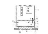
図1に示すように、電装品箱1は、正面から見て縦長長方形をなす。電装品箱1は、室外ユニット2の左側面に沿わせるように、室外熱交換器3の前方に配置されている。図2に示すように、電装品箱1は、電子部品収納部10と、吸込み通風路20と、冷却器30とから構成されている。
電子部品収納部10は、室外ユニット2の運転を制御する電子部品11を収納する。電子部品収納部10は、電装品箱1の下方部を除く上方に位置し、電装品箱1の大半部を占める。電子部品収納部10は、電子部品11を冷却する空気を取り込む連絡口12と、電装品箱1内の空気を排出する排出口13とを備えている。連絡口12は、電子部品収納部10の底面に形成されている。排出口13は、室外送風機4の吸込側により近くなるように電子部品収納部10の背面上部に位置して形成されている。連絡口12及び排出口13をこのように配置することにより、室外送風機4の運転とともに電子部品11を冷却する空気が電子部品収納部10内に取り込まれ、電子部品11を冷却した後に排出される。
図2に示すように、吸込み通風路20は、上下方向の中間位置に内部を上下二分する水平仕切板21を備えている。吸込み通風路20は、水平仕切板21の下方部の右側方には室外ユニット2内の空気を吸入する吸入口22が設けられている。室外ユニット2内には、室外熱交換器3を通過した後の空気が流通している。吸込み通風路20は、吸入口22から吸入した空気を電子部品収納部10の連絡口12へ案内する通風路を構成する。
吸込み通風路20は、水平仕切板21の下方部を下方通路部23とし、水平仕切板21の上方部を上方通路部24としている。下方通路部23と上方通路部24とは、水平仕切板21の左側方においてU字状に連通するように構成されている。吸込み通風路20の上方通路部24は、右側方において、電子部品収納部10に連通するように構成されている。
吸入口22から吸入された室外ユニット2内の空気は、下方通路部23により左側方へ搬送され、左側方部において上方に向けて通風方向を180度転換し、上方通路部24において右側方へ搬送される。この吸込み通風路20の左側方部における通風方向の転換部を第1の転向部25とする。上方通路部24を搬送される空気は、右側方部において通風方向を90度転換して連絡口12を介し電子部品収納部10へ導入される。この上方通路部24の右側方部における通風方向の転換部を第2の転向部26とする。したがって、本実施形態においては、吸入口22から電子部品収納部10に至る吸込み通風路20は、二つの転向部25、26を備えている。
冷却器30は、低圧低温の冷媒を冷熱源とする。冷却器30は、冷熱源としての冷媒を流通させる冷熱源部31と、冷熱源部31により冷却されるヒートシンク32とを有する。ヒートシンク32は、基部33と、基部33と一体に形成されるフィン部34とを有する。
冷熱源部31は、冷熱源としての冷媒を流通させて基部33と熱交換して、ヒートシンク32を電装品箱1の外部温度より低くなるように冷却している。本実施形態における冷熱源部31は、冷媒配管により構成されている。ヒートシンク32は、アルミニウム、銅などの伝熱性能の良い材料により形成されているものであって、基部33とフィン部34とから構成されている。ヒートシンク32は、吸込み通風路20の左側面に構成された開口部において、外部から転向部25に対し差し込み式に挿入されて固定されている。
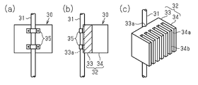
図2に示すように、基部33は、厚手の板状を成し、転向部25の左側壁の開口部を貫通する状態で固定されている。したがって、基部33は、吸込み通風路20の左側面の開口部を閉蓋する壁を兼用する。図3(a)~(c)に示すように、基部33の左側面には、冷熱源部31を構成する冷媒配管を埋め込み式に沿わせるための凹溝33aが形成されている。冷熱源部31を構成する冷媒配管は、基部33の背面に止め金35をビス止めすることにより固定されている。
フィン部34は、吸込み通風路20の下方通路部23から上方通路部24へ180度方向転換する空気と熱交換する。ヒートシンク32は、左側側方部の厚手の板状を成す基部33と右側方部のフィン部34とが一体化されている。フィン部34は、複数の溝状部34aと複数のフィン34bとからなる。吸込み通風路20の下方通路部23から転向部25へ流れてきた空気は、溝状部34aに入り、フィン34bの表面や基部33の前面側表面(すなわち、溝状部34aの底面)との熱交換により冷却されながら通風方向を180度転換している。
(第1実施形態の作用)
第1実施形態の電装品箱1は以上のように形成されているので、次のように冷却される。
第1実施形態の電装品箱1は以上のように形成されているので、次のように冷却される。
室外ユニット2を有する空気調和機が運転開始されると、圧縮機や室外送風機4が運転される。電装品箱1内に収納される、空気調和機の運転を制御する電子部品11は、空気調和機の運転に伴い発熱する。電子部品11の中でも圧縮機の駆動回路としてのインバータ装置を構成するパワーディバイスは発熱量が大きい。空気調和機の運転に伴い電装品箱1の周囲には、室外熱交換器3通過後の空気が流通する。この空気には、砂塵、塵埃、雨水、海水等が含まれている。また、冷熱源部31を構成する冷媒配管には、低温の冷媒が流通される。これに伴って、冷却器30のフィン部34が所定の温度に制御される。また、電装品箱1の排出口13が吸入口22よりも室外送風機4の吸込側により近いので、電装品箱1の排出口13付近の圧力が吸入口22付近の圧力よりも低くなる。この結果、電装品箱1内の空気が排出され、電装品箱1の周囲の空気が電子部品11を冷却する空気として吸入口22から吸入される。
吸入口22から吸入された空気は、吸込み通風路20の下方通路部23により第1の転向部25に案内される。そして、転向部25へ案内された空気は、転向部25で通風方向を上方へ180度転換されるため、空気中に含まれる砂塵、塵埃、雨水、海水等が遠心力により分離される。また、転向部25へ案内された空気は、冷却器30のヒートシンク32の表面で冷却除湿されて、第2の転向部26へ流れる。空気は、転向部26で空気中に残存する砂塵、塵埃、雨水、海水等が遠心力によりさらに除去されて、連絡口12を介して電子部品収納部10へ導入される。電子部品収納部10へ導入された空気は、電子部品収納部10内において電子部品11を十分に冷却した後、排出口13から室外送風機4の吸入側へ排出される。この排出された空気は、室外送風機4に吸い込まれて室外ユニット2の外部へ放出される。
(第1実施形態の効果)
本電装品箱1は、以上のように構成されているので、次のような効果を奏する。
本電装品箱1は、以上のように構成されているので、次のような効果を奏する。
(1-1)室外ユニット2内の室外熱交換器3通過後の空気を、冷媒を冷熱源とする冷却器30により電子部品収納部10へ供給する前に冷却しているので、外気温度の高い地域においも電子部品11を冷却することができる。
(1-2)冷却器30は、吸込み通風路20において電子部品収納部10へ供給する空気を冷却するように構成されているので、冷却器30を簡易な構成とすることができる。
(1-3)電子部品収納部10へ供給する空気中に含まれる砂塵、塵埃、雨水、海水等を第1の転向部25及び第2の転向部26で分離することができ、砂塵、塵埃、雨水、海水等の電子部品収納部10への侵入堆積を低減することができる。したがって、外気温度が高く、ほこりの多い地域向けの空気調和機における電装品箱1として好適である。なお、第1の転向部25及び第2の転向部26における塵、塵埃、雨水、海水等の分離は前者が主であり、後者は補助的なものとなる。
(第2実施形態)
次に、第2実施形態に係る電装品箱1について図4に基づき説明する。なお、第1実施形態と同一の部分には同一の符号を付し、その説明を簡略化する。
次に、第2実施形態に係る電装品箱1について図4に基づき説明する。なお、第1実施形態と同一の部分には同一の符号を付し、その説明を簡略化する。
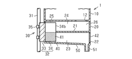
第2実施形態に係る電装品箱1は、冷却器30のヒートシンク32におけるフィン部34に、電子部品11を冷却する空気中に含まれる砂塵、塵埃、雨水、海水等を除去するフィルタ部40を設けるとともに、ヒートシンク32で発生する結露水を排出することができるようにしたものである。
図4に示すように、第2実施形態に係る電装品箱1に設けられる冷却器30のヒートシンク32は、フィン部34の下半分の表面に樹脂製の植毛41を施してフィルタ部40を形成している。また、ヒートシンク32の下方において、下方通路部23の底面壁にヒートシンク32で発生して下方へ滴下する結露水を集めるための溜まり部50を形成している。また、この溜まり部50の最下部にドレン排出口51を設けている。
第2実施形態に係る電装品箱1は、第1実施形態に係る電装品箱1と同様の作用効果を奏するとともに、次の効果を奏することができる。
(2-1)電子部品11を冷却する空気中に含まれる砂塵、塵埃、雨水、海水等は、植毛41を施したフィルタ部40を通過することにより、より一層除去される。
(2-2)フィルタ部40に付着する砂塵、塵埃、雨水、海水等は、ヒートシンク32で発生する結露水により洗い流されるので、ヒートシンク32の性能低下を抑制することができる。
(2-3)冷却器30のヒートシンク32で発生した結露水を排出することができる。これにより結露水の再飛散を抑制することができる。
(2-4)冷却器30のヒートシンク32におけるフィルタ部40で除去された空気中の砂塵、塵埃、雨水、海水等は、結露水により洗い流され、結露水とともにドレン排出口51から排出される。
(第3実施形態)
次に、第3実施形態に係る電装品箱1について図5に基づき説明する。なお、第2実施形態と同一の部分には同一の符号を付し、その説明を簡略化する。
次に、第3実施形態に係る電装品箱1について図5に基づき説明する。なお、第2実施形態と同一の部分には同一の符号を付し、その説明を簡略化する。
第3実施形態に係る電装品箱1は、第2実施形態に係る電装品箱1において溜まり部50を変形し、さらに吸入口22から吸入される空気に含まれる塵埃を除去するプレフィルタ42を設けたものである。
図5に示すように、第3実施形態に係る電装品箱1に設けられる溜まり部50は、下方通路部23の底面壁の略全体を右側方に向かって下方に傾斜させたものとしている。そしてこの溜まり部50の最下部となる右側方部にドレン排出口51を設けている。また、吸入口22にプレフィルタ42を着脱自在に設けている。プレフィルタ42は、空気調和機の室内空気吸込口に一般に使用されている繊維素材を枠内固定したようなものでよい。
第3実施形態に係る電装品箱1は、第2実施形態に係る電装品箱1と同様の作用効果を奏するとともに、次の効果を奏することができる。
(3-1)結露水を下方通路部23の底面壁の右側方部に集めて排出するので、フィン部34に付着した塵埃等を洗い流すとともに、下方通路部23の底面壁に付着した塵埃等も洗い流すことができる。
(3-2)吸入口22にプレフィルタ42を設けているので、下方通路部23に導入される空気中の、砂塵、塵埃、雨水、海水等を除去することができる。これにより、電子部品収納部10への砂塵、塵埃、雨水、海水等の侵入堆積をより軽減することができる。
(第4実施形態)
次に、第4実施形態に係る電装品箱1について図6に基づき説明する。なお、第1実施形態と同一の部分には同一の符号を付し、その説明を簡略化する。
次に、第4実施形態に係る電装品箱1について図6に基づき説明する。なお、第1実施形態と同一の部分には同一の符号を付し、その説明を簡略化する。
第4実施形態に係る電装品箱1は、第1実施形態に係る電装品箱1において冷却器30のヒートシンク32におけるフィン部34を変形したものである。
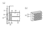
図6(a)及び図6(b)に示すように、第4実施形態に係る電装品箱1に設けられる冷却器30のヒートシンク32は、第1実施形態におけるフィン34bをピンフィンとしたものである。
第4実施形態に係る電装品箱1は、第2実施形態に係る電装品箱1と同様の作用効果を奏するとともに、次の効果を奏することができる。
(4-1)電子部品収納部10へ供給される空気がピンフィンとの衝突を繰り返しながら方向転換されるので、このフィン部34にて空気中に含まれる砂塵、塵埃、雨水、海水等をより除去することができる。
(第5実施形態)
次に、第5実施形態に係る電装品箱1について図7に基づき説明する。なお、第2実施形態と同一の部分には同一の符号を付し、その説明を簡略化する。
次に、第5実施形態に係る電装品箱1について図7に基づき説明する。なお、第2実施形態と同一の部分には同一の符号を付し、その説明を簡略化する。
第5実施形態に係る電装品箱1は、第2実施形態に係る電装品箱1において、ヒートシンク32のフィン部34に設けるフィルタ部40を変形したものである。
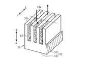
図7に示すように、第5実施形態に係るフィルタ部40は、第2実施形態におけるフィルタ部40としての植毛41に代わり、金属製繊維43をフィン34bの間の溝状部34aに詰め込み、これをフィルタ部40としたものである。
第5実施形態に係る電装品箱1は、第2実施形態に係る電装品箱1と同様の作用効果を奏するとともに、次の効果を奏することができる。
(5-1)フィルタ部40の構成部材が金属製であるので、塵埃等を除去するだけでなくフィン部34の熱交換能力を向上させることができる。
(第6実施形態)
次に、第6実施形態に係る電装品箱1について図8に基づき説明する。なお、第1実施形態と同一の部分には同一の符号を付し、その説明を簡略化する。
次に、第6実施形態に係る電装品箱1について図8に基づき説明する。なお、第1実施形態と同一の部分には同一の符号を付し、その説明を簡略化する。
第6実施形態に係る電装品箱1は、第1実施形態において吸込み通風路20及び冷却器30の構成を変更したものである。
図8に示すように、第6実施形態に係る電装品箱1は、吸込み通風路20の内部に冷却器30のヒートシンク32を挿入しないものである。冷却器30は、冷却源としての冷媒を導入する冷熱源部31を単なる冷媒配管とし、この冷媒配管を吸込み通風路20の左側面及び底面に沿わせている。この実施形態における冷却器30は、吸込み通風路20の左側面及び底面を介して電子部品収納部10へ供給する空気を冷却するようにしたものである。したがって、冷却器30は、冷熱源部31、吸込み通風路20の左側面及び底面を構成部材とする。
第6実施形態に係る電装品箱1は、第1実施形態に係る電装品箱1と同様の作用効果を奏するとともに、次の効果を奏することができる。
(6-1)冷却器30及び吸込み通風路20の構成が簡素化される。冷熱源部31は、吸込み通風路20の少なくとも一部の外表面を冷却するものであればよく、簡素な構造とすることができる。
(第7実施形態)
次に、第7実施形態に係る電装品箱1について図9に基づき説明する。なお、第1実施形態と同一の部分には同一の符号を付し、その説明を簡略化する。
次に、第7実施形態に係る電装品箱1について図9に基づき説明する。なお、第1実施形態と同一の部分には同一の符号を付し、その説明を簡略化する。
第1実施形態に係る電装品箱1は、電子部品収納部10と吸込み通風路20とを一体に形成していたが、第7実施形態に係る電装品箱1は、これらを分離可能、及び、分離して製作できるようにしたものである。
図9に示すように、第7実施形態に係る電装品箱1は、電子部品11を収納した電子部品収納部10と吸込み通風路20との仕切壁を、電子部品収納部10の底面としている、したがって、電子部品収納部10は、それ自身密閉空間を形成する独立の筐体として形成されている。
一方、吸込み通風路20は、上面壁のない形態であって、前記第1実施形態と同様の構造で製作される。図9においては、冷熱源部31としての配管が取り付けられて示されているが、冷熱源部31は、吸込み通風路20と電子部品収納部10とを組み付けた後、或いは、吸込み通風路20を電子部品収納部10へ組み付ける際に取り付けられる。したがって、吸込み通風路20の製作としては、冷熱源部31を取り付けていない状態のものを制作すればよい。
また、冷却器30を構成するヒートシンク32は、吸込み通風路20の筐体を完成させた後に組み付けすればよい。また、冷却器30を構成するヒートシンク32の吸込み通風路20への組み込みは、吸込み通風路20の筐体の電子部品収納部10への組み付けの前後何れであってもよい。
第7実施形態に係る電装品箱1は、第1実施形態に係る電装品箱1と同様の作用効果を奏するとともに、次の効果を奏することができる。
(7-1)本電装品箱1は、電子部品収納部10と吸込み通風路20とを分離可能、及び、分離して製作できるようにしているので、吸込み通風路20および冷却器30を外気温度の高い地域向けのオプションとして取り扱うことができる。
(第8実施形態)
次に、第8実施形態に係る電装品箱1について図10に基づき説明する。なお、第1実施形態と同一の部分には同一の符号を付し、その説明を簡略化する。
次に、第8実施形態に係る電装品箱1について図10に基づき説明する。なお、第1実施形態と同一の部分には同一の符号を付し、その説明を簡略化する。
第8実施形態に係る電装品箱1は、第1実施形態において吸込み通風路20を省略したものである。
図10に示すように、第8実施形態に係る電装品箱1は、電子部品収納部10の連絡口12の下方に冷却器30を取り付けている。冷却器30は、第1実施形態における冷却器30を左右対称的にした構成を基本としている。冷熱源部31及びヒートシンク32は第1実施形態と同一である。ただし、この実施形態においては、連絡口12の開口位置及び開口寸法と、フィン部34の平面上の位置及び平面寸法とを略一致させている。また、フィン部34の溝状部34aの下面を塞ぐ閉鎖板36をヒートシンク32の下面に取り付けている。これにより、室外ユニット2内の空気は、ヒートシンク32の左側方から連絡口12に向けて通風方向を転換させながら電子部品収納部10へ吸入される。この場合に、通風方向の転換角度は45度以上としている。ヒートシンク32は、通風方向を45度以上転換させることにより、砂塵、塵埃、雨水、海水等を除去する第1の転向部25を成している。
第8実施形態に係る電装品箱1は、第1実施形態に係る電装品箱1と同様の作用効果を奏するとともに、次の効果を奏することができる。
(8-1)吸込み通風路20を設けないので、電装品箱1を簡素化することができる。
(第9実施形態)
次に、第9実施形態に係る電装品箱1について図11に基づき説明する。なお、第1実施形態と同一の部分には同一の符号を付し、その説明を簡略化する。
次に、第9実施形態に係る電装品箱1について図11に基づき説明する。なお、第1実施形態と同一の部分には同一の符号を付し、その説明を簡略化する。
第9実施形態に係る電装品箱1は、吸込み通風路20及び冷却器30の構成を変更したものである。
図11に示すように、第9実施形態に係る電子部品収納部10は、第1実施形態と同一である。第9実施形態に係る吸込み通風路20は、水平仕切板21を廃止し、左側方に吸入口22を設け、左側方の吸入口22から吸入した室外ユニット2内の空気を右側方の連絡口12の手前までへ直線的に案内するようにしたものである。この場合、吸込み通風路20内を流通する空気は、右側方部において通風方向を90度転換して連絡口12を介して電子部品収納部10へ導入される。したがって、吸込み通風路20の右側方部は、通風方向を90度転換させることにより、砂塵、塵埃、雨水、海水等を除去する第1の転向部25を構成する。
また、この実施形態における冷却器30は、低温冷媒を流通させる冷媒配管から成る冷熱源部31と、厚手の板状部のみから成るヒートシンク32とを備えたものである。本実施形態における冷熱源部31は、第1実施形態における冷熱源部31に相当し、本実施形態におけるヒートシンク32は、第1実施形態におけるヒートシンク32の基部33のみを備えた構成に相当する。本実施形態におけるヒートシンク32は、吸込み通風路20の底面に密着して取り付けられている。
第9実施形態に係る電装品箱1は、第1実施形態に係る電装品箱1と同様の作用効果を奏するとともに、次の効果を奏することができる。
(9-1)吸込み通風路20は、上下2層とする必要がないので、簡素化されるとともに小型化される。また、ヒートシンク32も板状部材のみでよいので簡素化される。
(第10実施形態)
次に、第10実施形態に係る室外ユニット2の概略構成について図12に基づき説明する。なお、第1実施形態と同一の部分には同一の符号を付し、その説明を簡略化する。
次に、第10実施形態に係る室外ユニット2の概略構成について図12に基づき説明する。なお、第1実施形態と同一の部分には同一の符号を付し、その説明を簡略化する。
第10実施形態に係る室外ユニット2は、電装品箱1の吸入口22に外気が直接吸入されるように電装品箱1の構成を変更したものである。
図12に示すように、第10実施形態に係る電装品箱1は、第1実施形態と同様に室外ユニット2の左側面に沿わせるように、室外熱交換器3の前方に配置している。そして、第1実施形態においては、吸入口22が右側面に設けられていたが、本実施形態においては左側面に設けられ、吸入口22へは、外気が直接吸入されるように形成されている。なお、吸入口22から連絡口12に至る経路は、図示しないが第1実施形態と左右対称的に構成されている。また、室外ユニット2の左側面には、図示しないが吸入口22を外気に曝せる開口が設けられているものとする。
第10実施形態に係る電装品箱1は、第1実施形態に係る電装品箱1と同様の作用効果を奏するとともに、次の効果を奏することができる。
(10-1)電装品箱1に吸入される空気は、室外熱交換器3を通過する前の外気であるので、室外ユニット2内の空気より温度が低い。したがって、第1実施形態の場合に比し電子部品11の冷却効果を向上させることができる。
(10-2)また、吸入口22付近の圧力と排出口13付近の圧力との差が大きくなるので、電子部品収納部10へ導入される空気量を増大させることができる。その分冷却効果を向上させることができる。
(変更例)
上記各実施形態に関する説明は、本開示に従う電装品箱1の例示であり、その形態を制限することを意図していない。本開示に従う電装品箱1は、例えば以下に示される上記各実施形態の変更例、及び相互に矛盾しない少なくとも2つの変更例が組み合わせられた形態を取り得る。以下の変更例において、上記各実施形態と共通する部分は、上記各実施形態と同一の符号を付してその説明を省略する。
上記各実施形態に関する説明は、本開示に従う電装品箱1の例示であり、その形態を制限することを意図していない。本開示に従う電装品箱1は、例えば以下に示される上記各実施形態の変更例、及び相互に矛盾しない少なくとも2つの変更例が組み合わせられた形態を取り得る。以下の変更例において、上記各実施形態と共通する部分は、上記各実施形態と同一の符号を付してその説明を省略する。
・各実施形態において、冷却器30の冷熱源部31は、冷媒配管にて構成されていたが、内部に冷媒を流通させる平板状容器としてよい。また、吸込み通風路20の壁体を中空状の壁体とし、内部に冷媒を流通させるようにしたものでもよい。さらには、冷熱源部31として、低温冷媒を流通させる冷媒配管からなる構成に代えてサーモモジュールを用いてもよい。
・冷却器30のヒートシンク32は、空気の流れの方向転換を支障なく行えるものであれば、第1実施形態および第4実施形態以外の適宜の構造の物を採用することができる。
・第1実施形態~第7実施形態、及び第10実施形態において、転向部25,26は2か所であったが、転向部25,26の個数をさらに増加させてもよい。こうすれば、空気に含まれる砂塵、塵埃、雨水、海水等の除去をより確実とし、電子部品収納部10への侵入堆積を低減することができる。
・第3実施形態にプレフィルタ42を設けたが、他の実施形態においてこれと同様にプレフィルタ42を設けてもよい。逆に、第3実施形態において、他の実施形態と同様にプレフィルタ42を省略することもできる。
・第2実施形態及び第3実施形態には、ヒートシンク32で発生した結露水を受ける溜まり部50とドレン排出口51とを設けているが、他の実施形態においてもこれと同様に溜まり部50とドレン排出口51を設けてもよい。
・第10実施形態の電装品箱1は、第1実施形態の電装品箱1の変更例として説明しているが、第2実施形態~第9実施形態の電装品箱1においても第10実施形態と同様に変更してもよい。
以上、本開示の実施形態を説明したが、特許請求の範囲に記載された本開示の趣旨及び範囲から逸脱することなく、形態や詳細の多様な変更が可能なことが理解されるであろう。
Claims (9)
- 空気調和機の室外ユニット(2)に搭載され、筐体内部に電子部品(11)を収納した電装品箱(1)であって、
前記電子部品(11)を収納する電子部品収納部(10)と、
前記電装品箱(1)の外部から空気を吸入する吸入口(22)と、
前記電装品箱(1)の内部から空気を排出する排出口(13)と、
前記吸入口(22)から前記電子部品収納部(10)までの空気の流れの経路上に配置された、空気を冷却する冷却器(30)と、
を備えた電装品箱。 - 前記吸入口(22)から吸入された空気を前記電子部品収納部(10)へ案内する吸込み通風路(20)をさらに備え、
前記冷却器(30)は、前記吸込み通風路(20)内において空気を冷却するように構成されている
請求項1に記載の電装品箱。 - 前記吸込み通風路(20)は、通風方向を転換させる転向部(25,26)を少なくとも1個有する
請求項2に記載の電装品箱。 - 前記冷却器(30)は、前記電装品箱(1)の外部の空気よりも低い温度に冷却されるヒートシンク(32)を有し、前記ヒートシンク(32)を前記転向部(25,26)の内の少なくとも一つに配置するものであって、
前記ヒートシンク(32)は、前記転向部(25,26)において前記通風方向を転換させる基部(33a)と、前記基部(33a)に取り付けられる冷熱源部(31)と、前記基部(33a)の前記吸込み通風路(20)内に面する表面に形成されたフィン部(34)とを有する
請求項3に記載の電装品箱。 - 前記冷却器(30)は、空気中に含まれる塵埃を除去するフィルタ部(40)を備えている
請求項1~請求項4の何れか1項に記載の電装品箱。 - 前記フィルタ部(40)は、前記冷却器(30)における通過空気を冷却する表面に形成された植毛(41)からなる
請求項5に記載の電装品箱。 - 前記植毛(41)は、空気の流れの上流側の前記冷却器(30)における通過空気を冷却する表面にのみ形成されている
請求項6に記載の電装品箱。 - 前記冷却器(30)は、前記吸込み通風路(20)を形成する壁体の少なくとも一部を冷却するように構成されたものである
請求項2又は3に記載の電装品箱。 - 前記電装品箱(1)は、空気が前記冷却器(30)で冷却されることにより発生する結露水を排出するドレン排出口(51)を備えている
請求項1~8の何れか1項に記載の電装品箱。
Priority Applications (1)
| Application Number | Priority Date | Filing Date | Title |
|---|---|---|---|
| US17/440,956 US12050016B2 (en) | 2019-03-28 | 2020-03-25 | Electrical component box |
Applications Claiming Priority (2)
| Application Number | Priority Date | Filing Date | Title |
|---|---|---|---|
| JP2019064558A JP7355993B2 (ja) | 2019-03-28 | 2019-03-28 | 電装品箱 |
| JP2019-064558 | 2019-03-28 |
Publications (1)
| Publication Number | Publication Date |
|---|---|
| WO2020196576A1 true WO2020196576A1 (ja) | 2020-10-01 |
Family
ID=72609861
Family Applications (1)
| Application Number | Title | Priority Date | Filing Date |
|---|---|---|---|
| PCT/JP2020/013191 Ceased WO2020196576A1 (ja) | 2019-03-28 | 2020-03-25 | 電装品箱 |
Country Status (3)
| Country | Link |
|---|---|
| US (1) | US12050016B2 (ja) |
| JP (1) | JP7355993B2 (ja) |
| WO (1) | WO2020196576A1 (ja) |
Families Citing this family (2)
| Publication number | Priority date | Publication date | Assignee | Title |
|---|---|---|---|---|
| US12144142B2 (en) * | 2022-07-06 | 2024-11-12 | Crestron Electronics, Inc. | Dual mode cooling system for use with in-wall video-codec and other electronic circuits |
| JP2024023085A (ja) * | 2022-08-08 | 2024-02-21 | パナソニックIpマネジメント株式会社 | 電子機器 |
Citations (5)
| Publication number | Priority date | Publication date | Assignee | Title |
|---|---|---|---|---|
| JP2000022363A (ja) * | 1998-06-30 | 2000-01-21 | Mitsubishi Heavy Ind Ltd | 電気回路素子用放熱フィン、室外ユニット、及び空気調和機 |
| JP2010002120A (ja) * | 2008-06-19 | 2010-01-07 | Daikin Ind Ltd | 冷凍装置 |
| JP2014153019A (ja) * | 2013-02-12 | 2014-08-25 | Sharp Corp | ヒートポンプ機器の室外機 |
| JP2017009263A (ja) * | 2015-06-26 | 2017-01-12 | 株式会社富士通ゼネラル | 空気調和機 |
| JP2017120170A (ja) * | 2015-12-28 | 2017-07-06 | 株式会社マステック | ペルチェ素子を用いた製水装置 |
Family Cites Families (20)
| Publication number | Priority date | Publication date | Assignee | Title |
|---|---|---|---|---|
| US6658882B2 (en) * | 2001-08-09 | 2003-12-09 | Sanyo Electric Co., Ltd. | Integral-type air conditioner |
| AU2002250808A1 (en) * | 2002-02-27 | 2003-09-09 | Hansa Ventilatoren Und Maschinenbau Neumann Gmbh And Co. Kg | Air conditioning unit |
| JP2004301477A (ja) | 2003-04-01 | 2004-10-28 | Mitsubishi Heavy Ind Ltd | 室外機用電装箱および室外機ユニットおよび空気調和機 |
| CN100425918C (zh) * | 2003-09-25 | 2008-10-15 | 东芝开利株式会社 | 空调机的室外机单元 |
| JP4251114B2 (ja) * | 2004-06-02 | 2009-04-08 | パナソニック株式会社 | 放熱装置と電子機器、及び塵埃付着防止方法 |
| JP4093316B2 (ja) | 2004-09-29 | 2008-06-04 | 富士通株式会社 | 放熱フィンの製造方法 |
| US7441412B2 (en) * | 2005-01-26 | 2008-10-28 | Tim Allan Nygaard Jensen | Heat transfer system and method |
| JP2007285544A (ja) * | 2006-04-13 | 2007-11-01 | Matsushita Electric Ind Co Ltd | 空気調和機 |
| KR20080041072A (ko) * | 2006-11-06 | 2008-05-09 | 엘지전자 주식회사 | 공기조화기 |
| US8154886B2 (en) * | 2007-03-27 | 2012-04-10 | Commscope, Inc. Of North Carolina | Compact fiber panel with sliding tray having removable hood |
| JP2008103773A (ja) * | 2008-01-17 | 2008-05-01 | Fujitsu Ltd | 放熱フィン |
| WO2009137215A2 (en) * | 2008-05-05 | 2009-11-12 | Carrier Corporation | Integrated computer equipment container and cooling unit |
| JP2012137229A (ja) * | 2010-12-27 | 2012-07-19 | Panasonic Corp | 空気調和機の室外機 |
| JP2013011392A (ja) * | 2011-06-29 | 2013-01-17 | Panasonic Corp | 空気調和装置 |
| JP2014129982A (ja) * | 2012-12-28 | 2014-07-10 | Daikin Ind Ltd | 空調装置 |
| CN104390281B (zh) * | 2014-12-03 | 2015-09-09 | 江苏风神空调集团股份有限公司 | 利用盘式空气生态箱的空气调节方法 |
| KR102433388B1 (ko) * | 2015-10-22 | 2022-08-17 | 삼성전자주식회사 | 공기 조화기의 실외기, 이에 적용되는 냉각 유닛 및 냉각 유닛의 제조 방법 |
| US11391474B2 (en) * | 2016-08-04 | 2022-07-19 | Energy Wall Llc | System, components, and methods for air, heat, and humidity exchanger |
| US10288355B2 (en) * | 2017-07-05 | 2019-05-14 | Noren Products Inc. | Heat exchanger assemblies and methods for cooling the interior of an enclosure |
| EP3663663B1 (en) * | 2017-08-28 | 2022-05-18 | Daikin Industries, Ltd. | Air processing device |
-
2019
- 2019-03-28 JP JP2019064558A patent/JP7355993B2/ja active Active
-
2020
- 2020-03-25 WO PCT/JP2020/013191 patent/WO2020196576A1/ja not_active Ceased
- 2020-03-25 US US17/440,956 patent/US12050016B2/en active Active
Patent Citations (5)
| Publication number | Priority date | Publication date | Assignee | Title |
|---|---|---|---|---|
| JP2000022363A (ja) * | 1998-06-30 | 2000-01-21 | Mitsubishi Heavy Ind Ltd | 電気回路素子用放熱フィン、室外ユニット、及び空気調和機 |
| JP2010002120A (ja) * | 2008-06-19 | 2010-01-07 | Daikin Ind Ltd | 冷凍装置 |
| JP2014153019A (ja) * | 2013-02-12 | 2014-08-25 | Sharp Corp | ヒートポンプ機器の室外機 |
| JP2017009263A (ja) * | 2015-06-26 | 2017-01-12 | 株式会社富士通ゼネラル | 空気調和機 |
| JP2017120170A (ja) * | 2015-12-28 | 2017-07-06 | 株式会社マステック | ペルチェ素子を用いた製水装置 |
Also Published As
| Publication number | Publication date |
|---|---|
| JP7355993B2 (ja) | 2023-10-04 |
| JP2020165560A (ja) | 2020-10-08 |
| US12050016B2 (en) | 2024-07-30 |
| US20220163226A1 (en) | 2022-05-26 |
Similar Documents
| Publication | Publication Date | Title |
|---|---|---|
| CN105716156B (zh) | 除湿装置 | |
| CN104251521B (zh) | 除湿装置 | |
| WO2018154836A1 (ja) | 除湿機 | |
| WO2020196576A1 (ja) | 電装品箱 | |
| US11982462B2 (en) | Air conditioner | |
| JP2000018646A (ja) | 空気調和機の室外ユニット | |
| KR102218078B1 (ko) | 이동형 공기조화기 | |
| KR101962165B1 (ko) | 공기 조화기의 실외기 | |
| CN114424682B (zh) | 一种换热模块及机柜 | |
| CN219976689U (zh) | 一种换热芯体及空气调节单元 | |
| JP2008237390A (ja) | 洗濯乾燥機 | |
| CN215951615U (zh) | 一种半导体除湿系统及半导体除湿机 | |
| KR102436120B1 (ko) | 토출공기의 온도를 저감시킬 수 있는 제습기 | |
| KR20140125531A (ko) | 공기조화기 | |
| KR100436141B1 (ko) | 공기조화기의 실내기 | |
| KR100602693B1 (ko) | 공기조화기의 실외기 | |
| JP2017070924A (ja) | 除湿装置 | |
| CN114963650B (zh) | 制冷干燥设备 | |
| KR20070038353A (ko) | 천장형 공기조화기 | |
| KR100722994B1 (ko) | 스탠드형 에어컨 | |
| JP2003240257A (ja) | 空気調和装置の室内ユニット | |
| JP4789548B2 (ja) | 空気調和装置 | |
| JP2022001797A (ja) | 空気調和装置 | |
| JP2003222459A (ja) | 冷蔵庫 | |
| JP2023151974A (ja) | 熱交換器 |
Legal Events
| Date | Code | Title | Description |
|---|---|---|---|
| 121 | Ep: the epo has been informed by wipo that ep was designated in this application |
Ref document number: 20779056 Country of ref document: EP Kind code of ref document: A1 |
|
| NENP | Non-entry into the national phase |
Ref country code: DE |
|
| 122 | Ep: pct application non-entry in european phase |
Ref document number: 20779056 Country of ref document: EP Kind code of ref document: A1 |