WO2020196353A1 - 温度センサの取付構造体 - Google Patents
温度センサの取付構造体 Download PDFInfo
- Publication number
- WO2020196353A1 WO2020196353A1 PCT/JP2020/012572 JP2020012572W WO2020196353A1 WO 2020196353 A1 WO2020196353 A1 WO 2020196353A1 JP 2020012572 W JP2020012572 W JP 2020012572W WO 2020196353 A1 WO2020196353 A1 WO 2020196353A1
- Authority
- WO
- WIPO (PCT)
- Prior art keywords
- temperature sensor
- flow path
- fluid control
- control device
- piece
- Prior art date
- Legal status (The legal status is an assumption and is not a legal conclusion. Google has not performed a legal analysis and makes no representation as to the accuracy of the status listed.)
- Ceased
Links
Images



Classifications
-
- G—PHYSICS
- G01—MEASURING; TESTING
- G01K—MEASURING TEMPERATURE; MEASURING QUANTITY OF HEAT; THERMALLY-SENSITIVE ELEMENTS NOT OTHERWISE PROVIDED FOR
- G01K1/00—Details of thermometers not specially adapted for particular types of thermometer
- G01K1/14—Supports; Fastening devices; Arrangements for mounting thermometers in particular locations
-
- F—MECHANICAL ENGINEERING; LIGHTING; HEATING; WEAPONS; BLASTING
- F16—ENGINEERING ELEMENTS AND UNITS; GENERAL MEASURES FOR PRODUCING AND MAINTAINING EFFECTIVE FUNCTIONING OF MACHINES OR INSTALLATIONS; THERMAL INSULATION IN GENERAL
- F16K—VALVES; TAPS; COCKS; ACTUATING-FLOATS; DEVICES FOR VENTING OR AERATING
- F16K27/00—Construction of housing; Use of materials therefor
- F16K27/003—Housing formed from a plurality of the same valve elements
-
- F—MECHANICAL ENGINEERING; LIGHTING; HEATING; WEAPONS; BLASTING
- F16—ENGINEERING ELEMENTS AND UNITS; GENERAL MEASURES FOR PRODUCING AND MAINTAINING EFFECTIVE FUNCTIONING OF MACHINES OR INSTALLATIONS; THERMAL INSULATION IN GENERAL
- F16K—VALVES; TAPS; COCKS; ACTUATING-FLOATS; DEVICES FOR VENTING OR AERATING
- F16K37/00—Special means in or on valves or other cut-off apparatus for indicating or recording operation thereof, or for enabling an alarm to be given
-
- F—MECHANICAL ENGINEERING; LIGHTING; HEATING; WEAPONS; BLASTING
- F16—ENGINEERING ELEMENTS AND UNITS; GENERAL MEASURES FOR PRODUCING AND MAINTAINING EFFECTIVE FUNCTIONING OF MACHINES OR INSTALLATIONS; THERMAL INSULATION IN GENERAL
- F16K—VALVES; TAPS; COCKS; ACTUATING-FLOATS; DEVICES FOR VENTING OR AERATING
- F16K37/00—Special means in or on valves or other cut-off apparatus for indicating or recording operation thereof, or for enabling an alarm to be given
- F16K37/0025—Electrical or magnetic means
-
- G—PHYSICS
- G01—MEASURING; TESTING
- G01K—MEASURING TEMPERATURE; MEASURING QUANTITY OF HEAT; THERMALLY-SENSITIVE ELEMENTS NOT OTHERWISE PROVIDED FOR
- G01K13/00—Thermometers specially adapted for specific purposes
- G01K13/02—Thermometers specially adapted for specific purposes for measuring temperature of moving fluids or granular materials capable of flow
-
- G—PHYSICS
- G01—MEASURING; TESTING
- G01K—MEASURING TEMPERATURE; MEASURING QUANTITY OF HEAT; THERMALLY-SENSITIVE ELEMENTS NOT OTHERWISE PROVIDED FOR
- G01K7/00—Measuring temperature based on the use of electric or magnetic elements directly sensitive to heat ; Power supply therefor, e.g. using thermoelectric elements
-
- G—PHYSICS
- G01—MEASURING; TESTING
- G01K—MEASURING TEMPERATURE; MEASURING QUANTITY OF HEAT; THERMALLY-SENSITIVE ELEMENTS NOT OTHERWISE PROVIDED FOR
- G01K7/00—Measuring temperature based on the use of electric or magnetic elements directly sensitive to heat ; Power supply therefor, e.g. using thermoelectric elements
- G01K7/02—Measuring temperature based on the use of electric or magnetic elements directly sensitive to heat ; Power supply therefor, e.g. using thermoelectric elements using thermoelectric elements, e.g. thermocouples
-
- H—ELECTRICITY
- H10—SEMICONDUCTOR DEVICES; ELECTRIC SOLID-STATE DEVICES NOT OTHERWISE PROVIDED FOR
- H10P—GENERIC PROCESSES OR APPARATUS FOR THE MANUFACTURE OR TREATMENT OF DEVICES COVERED BY CLASS H10
- H10P72/00—Handling or holding of wafers, substrates or devices during manufacture or treatment thereof
- H10P72/06—Apparatus for monitoring, sorting, marking, testing or measuring
- H10P72/0602—Temperature monitoring
-
- F—MECHANICAL ENGINEERING; LIGHTING; HEATING; WEAPONS; BLASTING
- F16—ENGINEERING ELEMENTS AND UNITS; GENERAL MEASURES FOR PRODUCING AND MAINTAINING EFFECTIVE FUNCTIONING OF MACHINES OR INSTALLATIONS; THERMAL INSULATION IN GENERAL
- F16K—VALVES; TAPS; COCKS; ACTUATING-FLOATS; DEVICES FOR VENTING OR AERATING
- F16K37/00—Special means in or on valves or other cut-off apparatus for indicating or recording operation thereof, or for enabling an alarm to be given
- F16K37/0025—Electrical or magnetic means
- F16K37/005—Electrical or magnetic means for measuring fluid parameters
Definitions
- the present invention relates to a fluid control device used in a semiconductor manufacturing device or the like, and more particularly to a mounting structure of a temperature sensor to be mounted on a fluid control device with a heating device.
- various fluid control devices are arranged in a plurality of rows, and the flow paths of the fluid control devices in adjacent rows are connected to each other at a predetermined position by a device connecting means.
- integration has been promoted in which a mass flow controller, an on-off valve, and the like are connected without using a tube.
- a heating device may be required for the purpose of preventing dew condensation and preventing reliquefaction when gasifying and flowing a fluid that is liquid at room temperature.
- ribbon-shaped planar heaters are arranged on both sides of at least one line, and these planar heaters are held by a plurality of metal clips on the corresponding joint members. Is disclosed (Patent Document 1).
- a temperature sensor for temperature adjustment (for example, a thermoelectric pair, etc.) is attached to adjust overheating or underheating.
- a temperature sensor for temperature adjustment has been operated by attaching it to a flow path block on which a fluid control device is placed, particularly a flow path block on the downstream side of a mass flow controller that controls the flow rate, using adhesive tape. It was.
- the present invention has been made in view of this point, and an object of the present invention is to provide a temperature sensor mounting structure that can reliably fix a temperature sensor and can be retrofitted to a standard component. It is in.
- the temperature sensor mounting structure according to the present invention made to solve the above problems includes a plurality of flow path blocks having a fluid flow path inside and having an opening of the flow path on at least one surface, and the flow path.
- a temperature sensor mounting structure to be mounted on the flow path block of an integrated fluid control device including a fluid control device mounted on a road block, in which a rectangular temperature sensor mounting piece and the mounting piece face each other. It is equipped with a pair of holding pieces extending from the opposite side.
- the stopper piece can be extended inward from the lower side of at least one of the temperature sensor mounting piece and the holding piece.
- the temperature sensor is attached to the upper block (fluid control device (flow rate controller, automatic on-off valve, etc.)) mounted on the flow path block (lower block).
- the end side of the anti-temperature sensor mounting piece of the holding piece can be provided with a bent portion that bends inward. It prevents the bent portion from being caught on the anti-temperature sensor mounting surface of the flow path block and falling off even if horizontal stress is applied to the mounting structure.
- the surface of the temperature sensor mounting piece can be covered with a band-shaped heating means.
- a temperature sensor mounting structure that can be reliably fixed to a flow rate control device, particularly an integrated flow rate control device, and can also be retrofitted to standard parts.
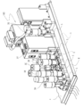
- FIG. 1 It is a perspective view which shows the integrated flow rate control device before mounting the mounting structure of the temperature sensor which concerns on embodiment of this invention. It is a perspective view which shows the integrated flow rate control device after mounting the mounting structure of the temperature sensor.
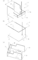
- FIG. 1 shows the perspective view of the mounting structure of the temperature sensor.
- FIG. 1 shows the perspective view of the mounting structure of the temperature sensor.
- a third embodiment of the mounting structure of the temperature sensor is shown, (a) is a perspective view, (b) is a plan view, (c) is a plan view explaining the process of mounting on the block, and (d) is mounted on the block. It is a top view which shows the state.
- Embodiment 1 of the temperature sensor mounting structure of the present invention.
- the fluid control device 100 shown in FIG. 1 has a plurality of flow path blocks 2 provided with a plurality of fluid control devices 3A to 3G in the upper stage and a plurality of fluid flow paths inside in which the plurality of fluid control devices 3A to 3G are placed in the lower stage.
- a support member 4 that supports the plurality of flow path blocks 2, a heating means H that heats the surfaces of the flow path block 2 and the fluid control devices 3A to 3G, and the surfaces of the flow path block 2 or the fluid control devices 3A to 3G. It is provided with a temperature sensor S for measuring the temperature of the above, and a temperature sensor mounting structure 1 for mounting the temperature sensor S on the flow path block 2 or the fluid control devices 3A to 3G.
- the flow path block 2 and the fluid control devices 3A to 3G are regarded as one line, and two lines are displayed in the example, but the number of lines is not limited to this, and one line to multiple lines, depending on the equipment. The number of lines can be freely determined.
- Heating means H abuts on the side surface of the flow path block 2 and heats the temperature in the flow path to a predetermined temperature, and heats a gas (for example, hydrogen fluoride) flowing in through the inlet pipe. Prevents liquefaction of gas that liquefies at room temperature.
- a gas for example, hydrogen fluoride
- the heating means H that comes into contact with the side surface of the flow path block 2 is sandwiched and fixed by the clip 5.
- the height dimension of the heating means H composed of the planar heater is matched to the height dimension of the flow path block 2 (lower block), but the fluid control devices 3A to 3G (upper block) are shown. It may have a height that covers the lower side.
- the clip 5 is formed by bending a thin plate material so that the narrow pressure portion 5A extends in the vertical direction and is parallel to the side surfaces of the flow path block 2 and the fluid control devices 3A to 3G.
- the connecting portion 5B extends along the lateral direction of the gas line and connects the pair of narrowing portions 5A.
- the clip 5 attaches the temperature sensor mounting structure 1 and the heating means H to the flow path block 2 and the fluid control devices 3A to 3G, and fixes them so as to sandwich them.
- a silicone sponge heat insulating material that covers the surface of the heating means H and the upper surface of the block portion of the fluid controllers 3A to 3G may be arranged and fixed by the clip 5.
- the temperature sensor S mounted on the temperature sensor mounting structure 1 transmits the measured temperature of the flow path block 2 or the fluid control devices 3A to 3G to the control device (not shown) that controls the fluid control devices 3A to 3G. Therefore, the control device can control the fluid control devices 3A to 3G according to the measured temperature, and can also give an instruction to stop the device in an emergency when the temperature deviates from the predetermined temperature threshold.
- the temperature sensor S is not particularly limited, but in the present embodiment, a thermocouple is used. A thermostat can also be used as the temperature sensor S.
- the temperature sensor mounting structure 1 is mounted on the flow path block 2 or the fluid control device 3 described above, and extends from the rectangular temperature sensor mounting piece 10 and the opposite sides 10a and 10a of the mounting piece 10. It is provided with a pair of holding pieces 11.
- the temperature sensor mounting piece 10 and the holding pieces 11 and 11 are manufactured by bending one sheet metal. By bending the sheet metal, the holding pieces 11 and 11 have a spring property of returning to the original position even when expanded.
- the distance L (width dimension of the temperature sensor mounting piece 10) between the sandwiching pieces 11 and 11 is substantially the same as the width dimension of the flow path block 2 or the fluid control device 3 to be mounted. Usually, this width dimension, particularly the width dimension of the flow path block 2, is standardized in the integrated fluid control device, and it is not necessary to prepare many types.
- the opposite side 10a portion of the mounting piece 10 may be bent at a right angle to form the holding pieces 11 and 11 as shown in FIG. 3 (b), but in the present embodiment, the figure may be formed.
- the width dimension of the mounting piece 10 is slightly longer than the distance L between the holding pieces 11 and 11, the inside of the opposite side 10a is bent at an acute angle, and further orthogonal to the mounting piece 10.
- the holding pieces 11 and 11 are formed by bending. As a result, the springiness due to the bending process is enhanced, and the flow path block 2 can be reliably sandwiched between the sandwiching pieces 11 and 11.
- the upper sides of the holding pieces 11 and 11 are placed on the bottom surface of the fluid control device 3 placed on the adjacent flow path blocks 2. It is possible to prevent the temperature sensor S from coming out of the flow path block due to contact.
- the height dimensions of the mounting piece 10 and the holding pieces 11 and 11 may be the same as shown in FIG. 3 (b), but as shown in FIG. 3 (a), the mounting pieces are mounted.
- the height dimension of the piece 10 may be shorter than the height dimension of the sandwiching pieces 11 and 11.
- the temperature sensor mounting structure 1 has stopper pieces 12 and 13 inward from the lower side of at least one of the temperature sensor mounting piece 10 and the holding pieces 11 and 11. It can be configured to extend. It is preferable that the stopper pieces 12 and 13 are also cut out from one sheet metal and formed by bending.
- the stopper piece 12 is extended from the temperature sensor mounting piece 10, and the stopper piece 13 is extended from the holding pieces 11 and 11, but the stopper piece may be formed from any one place.
- the stopper piece 13 extending from the holding piece 11 cannot be used when there is no gap or step between the fluid control device 3 which is the upper block and the upper surface of the flow path block 2 which is the lower block. .. Therefore, it is preferable to form only the stopper piece 12 extending from the temperature sensor mounting piece 10.
- the stopper piece 12 as shown in FIG. 4, when the temperature sensor S is attached to the fluid control device 3 (upper block), an upward stress (pulling force) is applied to the temperature sensor S. Even in this case, the stopper piece 12 can come into contact with the lower surface of the upper block, and the temperature sensor S can be prevented from coming out of the flow path block.
- the temperature sensor mounting structure 1 can project the ends of the sandwiching pieces 11 and 11 on the anti-temperature sensor mounting piece side inward.
- the shape of the protruding portion is not particularly limited, but in the present embodiment, the end side is wound inward in an arc shape to form the protruding portion 11a.
- the shape of the protrusions 11a may be simply bent at the end.
- the distance M between the protrusions 11a and 11a is equal to the width size of the block (usually the distance L between the holding pieces 11 and 11). )
- the sandwiching pieces 11 and 11 are expanded, and the protrusions 11a and 11a are slid while sliding against the side surface of the block (see FIG. 5C). Due to the springiness, the protrusions 11a and 11a are caught on the opposite surface of the block, and even if not only upward stress (pulling force) but also horizontal stress is generated, the position of the temperature sensor S does not change and is firmly fixed. Will be done.
- the inside of the opposite side 10a portion described in the first embodiment can be bent at an acute angle, and the stopper pieces 12 and 13 described in the second embodiment can be formed.
- the temperature sensor mounting structure of the present invention can effectively prevent the temperature sensor mounted on the integrated fluid control device from coming off upward, and is therefore widely suitable for the integrated fluid control device. In addition to being able to be used, it can also be suitably used for attaching a temperature sensor to an existing integrated fluid control device.
- Temperature sensor mounting structure 10 Temperature sensor mounting piece 11 Holding piece 12 Stopper piece 13 Stopper piece 2 Flow path block (lower block) 3 Fluid control equipment (upper block) 4 Support member 5 Clip 100 Fluid control device S Temperature sensor H Heating means
Landscapes
- Physics & Mathematics (AREA)
- General Physics & Mathematics (AREA)
- Engineering & Computer Science (AREA)
- General Engineering & Computer Science (AREA)
- Mechanical Engineering (AREA)
- Measuring Temperature Or Quantity Of Heat (AREA)
- Valve Housings (AREA)
Abstract
Description
図1~図3に、本発明の温度センサの取付構造体の実施形態1を示す。
図1に示す流体制御装置100は、上段に複数の流体制御機器3A~3Gと、下段に複数の流体制御機器3A~3Gを載置する内部に流体流路を備えた複数の流路ブロック2と、複数の流路ブロック2を支持する支持部材4と、流路ブロック2及び流体制御機器3A~3Gの表面を加熱する加熱手段Hと、流路ブロック2又は流体制御機器3A~3Gの表面の温度を測定する温度センサSと、この温度センサSを流路ブロック2又は流体制御機器3A~3Gに取り付けるための温度センサの取付構造体1とを備えている。
加熱手段Hは、流路ブロック2の側面に当接し、流路内の温度を所定の温度まで加熱するもので、入口配管を介して流入するガス(例えば、フッ化水素)を加温し、常温で液化するガスの液化を防止する。
温度センサの取付構造体1に取り付けられる温度センサSは、流体制御機器3A~3Gを制御する制御機器(図示省略)に、計測した流路ブロック2又は流体制御機器3A~3Gの温度を送信するもので、制御機器は、計測された温度に応じて、流体制御機器3A~3Gを制御するとともに、所定温度の閾値から外れた場合、機器を緊急停止するように指示を出すこともできる。温度センサSは、特に限定するものではないが、本実施形態では熱電対を使用するようにしている。また、温度センサSは、サーモスタットを用いることもできる。
さらに、温度センサの取付構造体1は、図3(c)に示すように、温度センサ取付片10及び挟持片11、11の少なくとも一箇所の下辺から、内側に向かってストッパ片12、13を延設するように構成することができる。ストッパ片12、13も1枚の板金から切り出し、曲げ加工によって形成することが好ましい。
また、温度センサの取付構造体1は、図5(a)に示すように、挟持片11、11の反温度センサ取付片側の端辺を内側に向かって突出させることができる。突出する部分の形状は、特に限定するものではないが、本実施形態では端辺を、内側に円弧状に巻回することで突出部11aとなるようにしている。
10 温度センサ取付片
11 挟持片
12 ストッパ片
13 ストッパ片
2 流路ブロック(下部ブロック)
3 流体制御機器(上部ブロック)
4 支持部材
5 クリップ
100 流体制御装置
S 温度センサ
H 加熱手段
Claims (4)
- 内部に流体流路を備え、少なくとも一面に前記流路の開口部を備えた複数の流路ブロックと、該流路ブロック上に載置される流体制御機器とを備えた流体制御装置の前記流路ブロック又は流体制御機器に取り付ける温度センサの取付構造体であって、
矩形状の温度センサ取付片と、
該取付片の対向する対辺から延設される対となる挟持片とを備えた温度センサの取付構造体。 - 前記温度センサ取付片及び挟持片の少なくとも一箇所の下辺から、内側に向かってストッパ片を延設する請求項1に記載の温度センサの取付構造体。
- 前記挟持片の反温度センサ取付片の端辺は、内側に屈曲する屈曲部を設けた請求項1又は2に記載の温度センサの取付構造体。
- 前記温度センサ取付片は、表面が帯状の加熱手段で覆われている請求項1、2又は3に記載の温度センサの取付構造体。
Priority Applications (4)
| Application Number | Priority Date | Filing Date | Title |
|---|---|---|---|
| JP2021509358A JP7620983B2 (ja) | 2019-03-25 | 2020-03-23 | 温度センサの取付構造体 |
| CN202080024190.4A CN113631900A (zh) | 2019-03-25 | 2020-03-23 | 温度传感器的安装构造体 |
| US17/440,460 US20220163399A1 (en) | 2019-03-25 | 2020-03-23 | Attachment structure for temperature sensor |
| KR1020217034314A KR20210143270A (ko) | 2019-03-25 | 2020-03-23 | 온도 센서의 부착 구조체 |
Applications Claiming Priority (2)
| Application Number | Priority Date | Filing Date | Title |
|---|---|---|---|
| JP2019-075170 | 2019-03-25 | ||
| JP2019075170 | 2019-03-25 |
Publications (1)
| Publication Number | Publication Date |
|---|---|
| WO2020196353A1 true WO2020196353A1 (ja) | 2020-10-01 |
Family
ID=72609922
Family Applications (1)
| Application Number | Title | Priority Date | Filing Date |
|---|---|---|---|
| PCT/JP2020/012572 Ceased WO2020196353A1 (ja) | 2019-03-25 | 2020-03-23 | 温度センサの取付構造体 |
Country Status (6)
| Country | Link |
|---|---|
| US (1) | US20220163399A1 (ja) |
| JP (1) | JP7620983B2 (ja) |
| KR (1) | KR20210143270A (ja) |
| CN (1) | CN113631900A (ja) |
| TW (1) | TWI845647B (ja) |
| WO (1) | WO2020196353A1 (ja) |
Families Citing this family (3)
| Publication number | Priority date | Publication date | Assignee | Title |
|---|---|---|---|---|
| DE102021211940A1 (de) * | 2021-10-22 | 2023-04-27 | Siemens Aktiengesellschaft | Temperaturmessvorrichtung zur nichtinvasen Temperaturmessung, Temperaturmesssystem und Computerprogrammprodukt |
| CN118328226B (zh) * | 2024-06-17 | 2024-09-27 | 鸿舸半导体设备(上海)有限公司 | 气体系统集成模块及气体输送控制方法 |
| CN118654770B (zh) * | 2024-08-19 | 2024-10-25 | 深圳市铂电科技有限公司 | 一种电力设备用温度传感器及温度检测仪 |
Citations (2)
| Publication number | Priority date | Publication date | Assignee | Title |
|---|---|---|---|---|
| JP2016183906A (ja) * | 2015-03-26 | 2016-10-20 | 株式会社立山科学センサーテクノロジー | 蓄電池に対する温度センサ取付クリップ及び温度センサ取付構造 |
| JP2016191404A (ja) * | 2015-03-31 | 2016-11-10 | 株式会社フジキン | センサ保持具および流体制御装置 |
Family Cites Families (9)
| Publication number | Priority date | Publication date | Assignee | Title |
|---|---|---|---|---|
| JP4487135B2 (ja) * | 2001-03-05 | 2010-06-23 | 東京エレクトロン株式会社 | 流体制御装置 |
| JP4655423B2 (ja) * | 2001-07-05 | 2011-03-23 | 株式会社フジキン | 流体制御装置 |
| JP2005170547A (ja) * | 2003-12-08 | 2005-06-30 | Olympus Corp | 画像記録装置 |
| JP5113691B2 (ja) * | 2008-09-17 | 2013-01-09 | 株式会社パイオラックス | 温度センサの取付装置 |
| WO2014136557A1 (ja) * | 2013-03-08 | 2014-09-12 | 株式会社フジキン | 流体制御装置および流体制御装置へのサーマルセンサ設置構造 |
| JP6203076B2 (ja) * | 2014-02-19 | 2017-09-27 | 三菱電機株式会社 | サーミスタ取り付け構造、サーミスタ引き出し方法および空気調和機 |
| CN206804171U (zh) * | 2017-03-24 | 2017-12-26 | 天津中亚慧通科技有限公司 | 一种便于拆装的表面温度传感器的固定装置 |
| WO2018180886A1 (ja) * | 2017-03-30 | 2018-10-04 | 株式会社フジキン | 流体制御機器及びセンサ保持部材 |
| CN207675329U (zh) * | 2018-01-12 | 2018-07-31 | 惠州市亿能电子有限公司 | 一种温度传感器 |
-
2020
- 2020-03-23 WO PCT/JP2020/012572 patent/WO2020196353A1/ja not_active Ceased
- 2020-03-23 CN CN202080024190.4A patent/CN113631900A/zh active Pending
- 2020-03-23 US US17/440,460 patent/US20220163399A1/en not_active Abandoned
- 2020-03-23 JP JP2021509358A patent/JP7620983B2/ja active Active
- 2020-03-23 KR KR1020217034314A patent/KR20210143270A/ko not_active Ceased
- 2020-03-24 TW TW109109743A patent/TWI845647B/zh not_active IP Right Cessation
Patent Citations (2)
| Publication number | Priority date | Publication date | Assignee | Title |
|---|---|---|---|---|
| JP2016183906A (ja) * | 2015-03-26 | 2016-10-20 | 株式会社立山科学センサーテクノロジー | 蓄電池に対する温度センサ取付クリップ及び温度センサ取付構造 |
| JP2016191404A (ja) * | 2015-03-31 | 2016-11-10 | 株式会社フジキン | センサ保持具および流体制御装置 |
Also Published As
| Publication number | Publication date |
|---|---|
| KR20210143270A (ko) | 2021-11-26 |
| JPWO2020196353A1 (ja) | 2020-10-01 |
| JP7620983B2 (ja) | 2025-01-24 |
| CN113631900A (zh) | 2021-11-09 |
| TWI845647B (zh) | 2024-06-21 |
| US20220163399A1 (en) | 2022-05-26 |
| TW202041808A (zh) | 2020-11-16 |
Similar Documents
| Publication | Publication Date | Title |
|---|---|---|
| WO2020196353A1 (ja) | 温度センサの取付構造体 | |
| JP7365662B2 (ja) | ヒータ固定具および流体制御装置 | |
| US9970801B2 (en) | Thermal mass-flow meter and mass-flow control device using same | |
| US6554020B2 (en) | Fluid control apparatus | |
| JP2007333735A (ja) | 熱型流量センサ装置 | |
| JP4567370B2 (ja) | ガス供給集積ユニット | |
| JP6630483B2 (ja) | センサ保持具および流体制御装置 | |
| JP2011508193A (ja) | 乱流インデューサを備えた熱式流量センサー | |
| US20070169819A1 (en) | Fluid control apparatus with heating apparatus | |
| JP5860234B2 (ja) | 電熱ヒーター用基板 | |
| JP2021107715A (ja) | 流体制御装置 | |
| JP6844874B2 (ja) | 質量流量センサ、その質量流量センサを備えるマスフローメータ及びその質量流量センサを備えるマスフローコントローラ | |
| JP2008292484A (ja) | 集積タイプのマスフローコントローラを用いた流体供給機構 | |
| JP4435999B2 (ja) | マスフローコントローラを用いた流体供給機構および取替基板ならびにアタプタ | |
| JP2011220611A (ja) | 温度センサ取付具 | |
| JP2589318Y2 (ja) | マスフローメータおよびマスフローコントローラ | |
| EP3392621A1 (en) | Membrane-based thermal flow sensor device | |
| KR102661297B1 (ko) | 유체 제어 장치 | |
| CN204479193U (zh) | 感温包固定座、换热器及空调器 | |
| JP2016205553A (ja) | 断熱カバーおよび流体制御装置 | |
| CN100535819C (zh) | 温度调节器 | |
| TW202036195A (zh) | 流體控制裝置 | |
| JP7204203B2 (ja) | ヒータおよび流体制御装置 | |
| JP2008108277A (ja) | 集積タイプのマスフローコントローラ | |
| JP2002318149A (ja) | フローセンサ |
Legal Events
| Date | Code | Title | Description |
|---|---|---|---|
| 121 | Ep: the epo has been informed by wipo that ep was designated in this application |
Ref document number: 20776444 Country of ref document: EP Kind code of ref document: A1 |
|
| ENP | Entry into the national phase |
Ref document number: 2021509358 Country of ref document: JP Kind code of ref document: A |
|
| NENP | Non-entry into the national phase |
Ref country code: DE |
|
| ENP | Entry into the national phase |
Ref document number: 20217034314 Country of ref document: KR Kind code of ref document: A |
|
| 122 | Ep: pct application non-entry in european phase |
Ref document number: 20776444 Country of ref document: EP Kind code of ref document: A1 |