WO2020196190A1 - 蓄電装置 - Google Patents
蓄電装置 Download PDFInfo
- Publication number
- WO2020196190A1 WO2020196190A1 PCT/JP2020/012116 JP2020012116W WO2020196190A1 WO 2020196190 A1 WO2020196190 A1 WO 2020196190A1 JP 2020012116 W JP2020012116 W JP 2020012116W WO 2020196190 A1 WO2020196190 A1 WO 2020196190A1
- Authority
- WO
- WIPO (PCT)
- Prior art keywords
- power storage
- spacer
- storage element
- bulging portion
- axis
- Prior art date
Links
Images

Classifications
-
- H—ELECTRICITY
- H01—ELECTRIC ELEMENTS
- H01G—CAPACITORS; CAPACITORS, RECTIFIERS, DETECTORS, SWITCHING DEVICES OR LIGHT-SENSITIVE DEVICES, OF THE ELECTROLYTIC TYPE
- H01G11/00—Hybrid capacitors, i.e. capacitors having different positive and negative electrodes; Electric double-layer [EDL] capacitors; Processes for the manufacture thereof or of parts thereof
- H01G11/78—Cases; Housings; Encapsulations; Mountings
- H01G11/82—Fixing or assembling a capacitive element in a housing, e.g. mounting electrodes, current collectors or terminals in containers or encapsulations
-
- H—ELECTRICITY
- H01—ELECTRIC ELEMENTS
- H01M—PROCESSES OR MEANS, e.g. BATTERIES, FOR THE DIRECT CONVERSION OF CHEMICAL ENERGY INTO ELECTRICAL ENERGY
- H01M50/00—Constructional details or processes of manufacture of the non-active parts of electrochemical cells other than fuel cells, e.g. hybrid cells
- H01M50/20—Mountings; Secondary casings or frames; Racks, modules or packs; Suspension devices; Shock absorbers; Transport or carrying devices; Holders
- H01M50/233—Mountings; Secondary casings or frames; Racks, modules or packs; Suspension devices; Shock absorbers; Transport or carrying devices; Holders characterised by physical properties of casings or racks, e.g. dimensions
- H01M50/242—Mountings; Secondary casings or frames; Racks, modules or packs; Suspension devices; Shock absorbers; Transport or carrying devices; Holders characterised by physical properties of casings or racks, e.g. dimensions adapted for protecting batteries against vibrations, collision impact or swelling
-
- H—ELECTRICITY
- H01—ELECTRIC ELEMENTS
- H01G—CAPACITORS; CAPACITORS, RECTIFIERS, DETECTORS, SWITCHING DEVICES OR LIGHT-SENSITIVE DEVICES, OF THE ELECTROLYTIC TYPE
- H01G11/00—Hybrid capacitors, i.e. capacitors having different positive and negative electrodes; Electric double-layer [EDL] capacitors; Processes for the manufacture thereof or of parts thereof
- H01G11/10—Multiple hybrid or EDL capacitors, e.g. arrays or modules
- H01G11/12—Stacked hybrid or EDL capacitors
-
- H—ELECTRICITY
- H01—ELECTRIC ELEMENTS
- H01G—CAPACITORS; CAPACITORS, RECTIFIERS, DETECTORS, SWITCHING DEVICES OR LIGHT-SENSITIVE DEVICES, OF THE ELECTROLYTIC TYPE
- H01G11/00—Hybrid capacitors, i.e. capacitors having different positive and negative electrodes; Electric double-layer [EDL] capacitors; Processes for the manufacture thereof or of parts thereof
- H01G11/78—Cases; Housings; Encapsulations; Mountings
-
- H—ELECTRICITY
- H01—ELECTRIC ELEMENTS
- H01M—PROCESSES OR MEANS, e.g. BATTERIES, FOR THE DIRECT CONVERSION OF CHEMICAL ENERGY INTO ELECTRICAL ENERGY
- H01M50/00—Constructional details or processes of manufacture of the non-active parts of electrochemical cells other than fuel cells, e.g. hybrid cells
- H01M50/20—Mountings; Secondary casings or frames; Racks, modules or packs; Suspension devices; Shock absorbers; Transport or carrying devices; Holders
- H01M50/204—Racks, modules or packs for multiple batteries or multiple cells
- H01M50/207—Racks, modules or packs for multiple batteries or multiple cells characterised by their shape
- H01M50/209—Racks, modules or packs for multiple batteries or multiple cells characterised by their shape adapted for prismatic or rectangular cells
-
- H—ELECTRICITY
- H01—ELECTRIC ELEMENTS
- H01M—PROCESSES OR MEANS, e.g. BATTERIES, FOR THE DIRECT CONVERSION OF CHEMICAL ENERGY INTO ELECTRICAL ENERGY
- H01M50/00—Constructional details or processes of manufacture of the non-active parts of electrochemical cells other than fuel cells, e.g. hybrid cells
- H01M50/20—Mountings; Secondary casings or frames; Racks, modules or packs; Suspension devices; Shock absorbers; Transport or carrying devices; Holders
- H01M50/289—Mountings; Secondary casings or frames; Racks, modules or packs; Suspension devices; Shock absorbers; Transport or carrying devices; Holders characterised by spacing elements or positioning means within frames, racks or packs
- H01M50/291—Mountings; Secondary casings or frames; Racks, modules or packs; Suspension devices; Shock absorbers; Transport or carrying devices; Holders characterised by spacing elements or positioning means within frames, racks or packs characterised by their shape
-
- H—ELECTRICITY
- H01—ELECTRIC ELEMENTS
- H01G—CAPACITORS; CAPACITORS, RECTIFIERS, DETECTORS, SWITCHING DEVICES OR LIGHT-SENSITIVE DEVICES, OF THE ELECTROLYTIC TYPE
- H01G11/00—Hybrid capacitors, i.e. capacitors having different positive and negative electrodes; Electric double-layer [EDL] capacitors; Processes for the manufacture thereof or of parts thereof
- H01G11/74—Terminals, e.g. extensions of current collectors
- H01G11/76—Terminals, e.g. extensions of current collectors specially adapted for integration in multiple or stacked hybrid or EDL capacitors
-
- H—ELECTRICITY
- H01—ELECTRIC ELEMENTS
- H01M—PROCESSES OR MEANS, e.g. BATTERIES, FOR THE DIRECT CONVERSION OF CHEMICAL ENERGY INTO ELECTRICAL ENERGY
- H01M2220/00—Batteries for particular applications
- H01M2220/20—Batteries in motive systems, e.g. vehicle, ship, plane
-
- Y—GENERAL TAGGING OF NEW TECHNOLOGICAL DEVELOPMENTS; GENERAL TAGGING OF CROSS-SECTIONAL TECHNOLOGIES SPANNING OVER SEVERAL SECTIONS OF THE IPC; TECHNICAL SUBJECTS COVERED BY FORMER USPC CROSS-REFERENCE ART COLLECTIONS [XRACs] AND DIGESTS
- Y02—TECHNOLOGIES OR APPLICATIONS FOR MITIGATION OR ADAPTATION AGAINST CLIMATE CHANGE
- Y02E—REDUCTION OF GREENHOUSE GAS [GHG] EMISSIONS, RELATED TO ENERGY GENERATION, TRANSMISSION OR DISTRIBUTION
- Y02E60/00—Enabling technologies; Technologies with a potential or indirect contribution to GHG emissions mitigation
- Y02E60/10—Energy storage using batteries
-
- Y—GENERAL TAGGING OF NEW TECHNOLOGICAL DEVELOPMENTS; GENERAL TAGGING OF CROSS-SECTIONAL TECHNOLOGIES SPANNING OVER SEVERAL SECTIONS OF THE IPC; TECHNICAL SUBJECTS COVERED BY FORMER USPC CROSS-REFERENCE ART COLLECTIONS [XRACs] AND DIGESTS
- Y02—TECHNOLOGIES OR APPLICATIONS FOR MITIGATION OR ADAPTATION AGAINST CLIMATE CHANGE
- Y02T—CLIMATE CHANGE MITIGATION TECHNOLOGIES RELATED TO TRANSPORTATION
- Y02T10/00—Road transport of goods or passengers
- Y02T10/60—Other road transportation technologies with climate change mitigation effect
- Y02T10/70—Energy storage systems for electromobility, e.g. batteries
Definitions
- the present invention relates to a power storage device including a power storage element and a spacer.
- Patent Document 1 discloses a battery module (power storage device) in which a plurality of battery cells (power storage elements) are stacked with a holder (spacer) sandwiched between them.
- the spacer may be deformed.
- the spacer (holder) has a main body of the spacer (holder) in order to form a plurality of cooling air passages through which cooling air flows between the spacer (holder) and the power storage element (battery cell). It is bent like a corrugated sheet. Therefore, when the power storage element expands, the spacer is pressed against the power storage element, and as a result, the spacer is deformed so as to stretch.
- the inventor of the present application has found that the spacer may be deformed (stretched) in the power storage device having the above-mentioned conventional configuration.
- An object of the present invention is to provide a power storage device capable of suppressing deformation of a spacer.
- the power storage device includes a power storage element and a spacer arranged on one side of the first direction of the power storage element, and the spacer is placed in a second direction intersecting the first direction.
- a bulging portion that is extended and bulges to at least one side of the first direction and the other side of the first direction, and a flat plate arranged on one side of the bulging portion in the second direction. It has a part and.
- the present invention can be realized not only as such a power storage device but also as a spacer included in the power storage device.
- FIG. 1 is a perspective view showing the appearance of the power storage device according to the embodiment.
- FIG. 2 is an exploded perspective view showing each component when the power storage device according to the embodiment is disassembled.
- FIG. 3 is a perspective view showing the configuration of the power storage element according to the embodiment.
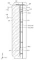
- FIG. 4 is a perspective view showing the configuration of the spacer according to the embodiment.
- FIG. 5 is a front view showing a configuration when a power storage element is arranged on the spacer according to the present embodiment.
- FIG. 6 is a cross-sectional view showing a configuration when a power storage element is arranged on the spacer according to the embodiment.
- FIG. 7 is a cross-sectional view showing a configuration when a power storage element is arranged on the spacer according to the embodiment.
- the power storage device includes a power storage element and a spacer arranged on one side of the first direction of the power storage element, and the spacer is placed in a second direction intersecting the first direction.
- a bulging portion that is extended and bulges to at least one side of the first direction and the other side of the first direction, and a flat plate arranged on one side of the bulging portion in the second direction. It has a part and.
- the spacers arranged on one side of the first direction of the power storage element are arranged on one side of the bulging portion extending in the second direction and the bulging portion in the second direction. It has a flat plate portion to be formed.
- the spacer tends to extend in the direction intersecting the extending direction of the bulging portion.
- the flat plate portion can be suppressed. As a result, even when the power storage element is swollen and the spacer is pressed against the power storage element, the spacer can be suppressed from being deformed.
- the bulging portion extends in the second direction and is arranged adjacent to the first bulging portion that bulges to one side in the first direction and the first bulging portion. It may have a second bulging portion that extends in two directions and bulges to the other side of the first direction.
- the bulging portion has a first bulging portion that bulges to one side in the first direction and a second bulging portion that bulges to the other side in the first direction. ing.
- the spacer has a plurality of the bulging portions arranged apart from each other in the first direction and the third direction intersecting the second direction, and the flat plate portion is the said portion of the plurality of bulging portions. It may be arranged on one side of the second direction.
- the spacer has a plurality of bulging portions arranged side by side, and the flat plate portion is arranged on one side in the second direction of the plurality of bulging portions.
- the stress when the power storage element swells can be dispersed to the plurality of bulging portions.
- the flat plate portion since the flat plate portion is arranged on one side of the plurality of bulging portions in the second direction, the flat plate portion can suppress the spacer from extending even if each bulging portion is recessed. As a result, it is possible to further suppress the deformation of the spacer.
- the power storage element may have a protruding portion that protrudes toward the flat plate portion.
- the power storage element may have a protruding portion.
- a protruding portion may be formed in the welded portion of the container to thicken the welded portion.
- a protrusion is formed on the lid side of the container body to widen the opening of the container body so that the contents such as the electrode body can be easily put in the container. In this way, when the protrusion is formed on the power storage element, the protrusion is projected toward the flat plate portion of the spacer.
- the spacer is further arranged on one side of the bulge portion in the second direction or the other side of the second direction, and extends in a third direction intersecting the first direction and the second direction. It may have a protrusion to be formed.
- the spacer has a protrusion extending in the third direction on the side of the bulging portion.
- the arrangement direction of the pair of electrode terminals in one storage element the opposite direction of the pair of short sides in the container of one storage element, the arrangement direction of the pair of side members, or the storage element and the side.
- the alignment direction with the members is defined as the X-axis direction.
- the thickness direction of the power storage element, spacer, or end member is defined as the Y-axis direction.
- the alignment direction of the container body and the lid of the electricity storage element, the arrangement direction of the energy storage element, the bus bar holding member and the bus bar, or the vertical direction is defined as the Z-axis direction.
- These X-axis directions, Y-axis directions, and Z-axis directions intersect each other (orthogonally in the present embodiment).
- the Z-axis direction may not be the vertical direction, but for convenience of explanation, the Z-axis direction will be described below as the vertical direction.
- the X-axis plus direction indicates the arrow direction of the X-axis in each figure
- the X-axis minus direction indicates the direction opposite to the X-axis plus direction.
- the Y-axis direction and the Z-axis direction may be referred to as a first direction
- the Z-axis direction may be referred to as a second direction
- the X-axis direction may be referred to as a third direction.
- the positive direction of the Y axis is defined as one side of the first direction
- the negative direction of the Y axis is defined as the other side of the first direction.
- the Z-axis plus direction is defined as one side of the second direction
- the Z-axis minus direction is defined as the other side of the second direction.
- expressions indicating relative directions or postures such as parallel and orthogonal include cases where they are not strictly the directions or postures.
- the fact that the two directions are orthogonal not only means that the two directions are completely orthogonal, but also that they are substantially orthogonal, that is, a difference of, for example, about several percent is included. It also means that.
- the power storage device 10 shown in FIG. 1 will be described as a case where the power storage device 10 is viewed in the positive direction of the Y-axis.
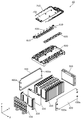
- FIG. 1 is a perspective view showing the appearance of the power storage device 10 according to the present embodiment.
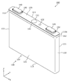
- FIG. 2 is an exploded perspective view showing each component when the power storage device 10 according to the present embodiment is disassembled.
- the power storage device 10 is a device capable of charging electricity from the outside and discharging electricity to the outside, and has a substantially rectangular parallelepiped shape in the present embodiment.
- the power storage device 10 is a battery module (assembled battery) used for power storage or power supply.
- the power storage device 10 is a battery for driving a moving body such as an automobile, a motorcycle, a watercraft, a snowmobile, an agricultural machine, a construction machine, or a railroad vehicle for an electric railway, or for starting an engine. Used as.
- Examples of the above-mentioned vehicle include an electric vehicle (EV), a hybrid electric vehicle (HEV), a plug-in hybrid electric vehicle (PHEV), and a gasoline vehicle.
- Examples of the above-mentioned railway vehicle for electric railways include trains, monorails, and linear motor cars.
- the power storage device 10 can also be used as a stationary battery or the like used for home use, a generator, or the like.
- the power storage device 10 includes a plurality of power storage elements 100, a plurality of spacers 200, a pair of end members 300, a pair of side members 400, and a bus bar holding member 500. It includes a bus bar 600 and a substrate 700.
- the power storage element 100 is a secondary battery (cell battery) capable of charging electricity and discharging electricity, and more specifically, a non-aqueous electrolyte secondary battery such as a lithium ion secondary battery.
- the power storage element 100 has a flat rectangular parallelepiped shape (square shape), and is arranged adjacent to the spacer 200. That is, each of the plurality of power storage elements 100 is alternately arranged with each of the plurality of spacers 200, and is arranged in the Y-axis direction. In the present embodiment, 13 spacers 200 are arranged at positions sandwiching each of the 12 power storage elements 100.
- the number of power storage elements 100 is not limited to 12, and may be a plurality of power storage elements other than 12, or may be one.
- the shape of the power storage element 100 is not particularly limited, and may be any shape such as a polygonal pillar shape, a cylindrical shape, an elliptical pillar shape, an oval pillar shape, etc. other than the rectangular parallelepiped shape. You can also do it.
- the power storage element 100 is not limited to the non-aqueous electrolyte secondary battery, and may be a secondary battery other than the non-aqueous electrolyte secondary battery, or may be a capacitor.
- the power storage element 100 may not be a secondary battery but a primary battery that can use the stored electricity without being charged by the user. Further, the power storage element 100 may be a battery using a solid electrolyte. A detailed description of the configuration of the power storage element 100 will be described later.
- the spacer 200 is a rectangular and plate-shaped spacer that is arranged in the Y-axis plus direction or the Y-axis minus direction of the power storage element 100 and electrically insulates the power storage element 100 from other members. Specifically, the spacer 200 is arranged between two adjacent power storage elements 100 and between the power storage element 100 at the end and the end member 300, and is arranged between the two power storage elements 100 and at the end. Insulate between the power storage element 100 and the end member 300. In the present embodiment, 13 spacers 200 are arranged corresponding to 12 power storage elements 100, but when the number of power storage elements 100 is other than 12, the number of spacers 200 is also the power storage element 100. It is changed according to the number of.
- the spacer 200 has a front side or back side (Y-axis minus direction side or Y-axis) of the short side surface (short side surface portion 122 described later) of the power storage element 100. Approximately half of the positive side) is also formed to cover. That is, recesses are formed on both the front side or the back side (both sides in the Y-axis direction) of the spacer 200, and substantially half of the power storage element 100 is inserted into the recesses. With such a configuration, the two spacers 200 sandwiching the power storage element 100 cover the short side surface of the power storage element 100, so that the electrical insulation between the power storage element 100 and the side member 400 can be ensured. ..
- the spacer 200 includes polycarbonate (PC), polypropylene (PP), polyethylene (PE), polyphenylene sulfide resin (PPS), polyphenylene ether (PPE (including modified PPE)), polyethylene terephthalate (PET), and polyetheretherketone (PET). Insulation of PEEK), tetrafluoroethylene / perfluoroalkyl vinyl ether (PFA), polytetrafluoroethylene (PTFE), polybutylene terephthalate (PBT), polyether sulfone (PES), ABS resin, and composite materials thereof. It is made of the resin material of.
- the spacer 200 may be made of a material other than resin as long as it has electrical insulating properties, and is made of ceramic, a dammer material formed by accumulating and bonding mica pieces, or the like. May be good. Not all of the plurality of spacers 200 need to be made of the same material. A more detailed description of the configuration of the spacer 200 will be described later.
- the end member 300 and the side member 400 are members that press the power storage element 100 from the outside in the arrangement direction (Y-axis direction) of the plurality of power storage elements 100. That is, the end member 300 and the side member 400 sandwich the plurality of power storage elements 100 from both sides in the arrangement direction, thereby pressing each storage element 100 included in the plurality of storage elements 100 from both sides in the arrangement direction.
- the end members 300 are arranged on both sides of the plurality of power storage elements 100 in the Y-axis direction, and the plurality of power storage elements 100 are sandwiched from both sides in the arrangement direction (Y-axis direction) of the plurality of power storage elements 100. It is a flat block-shaped end plate (holding member) to be held.
- the end member 300 is made of a metal (conductive) material such as aluminum, aluminum alloy, stainless steel, iron, and galvanized steel sheet from the viewpoint of ensuring strength.
- the material of the end member 300 is not particularly limited, and may be formed of, for example, a high-strength insulating material or may be subjected to an insulating treatment.
- the end member 300 may be a plate-shaped end plate or the like instead of a block-shaped end plate.
- the side members 400 are arranged on both sides of the plurality of power storage elements 100 in the X-axis direction, and both ends are attached to the end members 300 to restrain the plurality of power storage elements 100.
- Long and flat side plates consisttraint members, Restraint bar. That is, the side member 400 is arranged so as to extend in the Y-axis direction so as to straddle the plurality of power storage elements 100 and the plurality of spacers 200, and these are arranged with respect to the plurality of power storage elements 100 and the plurality of spacers 200.
- a binding force is applied in the direction (Y-axis direction).
- a pair of side members 400 are arranged on both sides of the plurality of power storage elements 100 and the plurality of spacers 200 in the X-axis direction.
- Each of the pair of side members 400 is attached to the X-axis direction ends of the pair of end members 300 at both ends in the Y-axis direction.
- the pair of side members 400 sandwich and restrain the plurality of power storage elements 100 and the plurality of spacers 200 from both sides in the X-axis direction and both sides in the Y-axis direction.
- the side member 400 is joined to the end member 300 by a plurality of joining members 400a arranged in the Z-axis direction.
- the joining member 400a is a bolt that penetrates the side member 400 and is fastened to the end member 300.
- the side member 400 is made of a metal (conductive) material such as aluminum, aluminum alloy, stainless steel, iron, or plated steel plate from the viewpoint of ensuring strength. It may be made of a highly insulating member, or may be insulated.
- the side member 400 may be a block-shaped or rod-shaped member or the like instead of a plate-shaped side plate.
- the bus bar holding member 500 holds the bus bar 600, the substrate 700, and the like, and is a plate-shaped member (bus bar) capable of electrically insulating the bus bar 600 and the like from other members and restricting the position of the bus bar 600 and the like. Plate, bus bar frame).
- the bus bar holding member 500 is made of an insulating resin material or the like similar to the spacer 200 such as PC, PP, PE.
- the bus bar 600 is a conductive plate-shaped member that is arranged on a plurality of power storage elements 100 and electrically connects the electrode terminals (electrode terminals 140 described later) of the plurality of power storage elements 100.
- a plurality of bus bars 600 are used to connect the positive electrode terminals and the negative electrode terminals of the adjacent storage element 100s in order to connect the plurality of storage elements 100 in series.
- An external terminal 610 (positive electrode external terminal, negative electrode external terminal), which is a terminal of the power storage device 10, is connected to the bus bar 600 arranged at the end.
- the bus bar 600 and the electrode terminals are connected by laser welding.
- the bus bar 600 also includes a wiring connection portion for detecting the voltage of the power storage element 100 and the like, and the connection portion is bent in the Z-axis plus direction.
- the bus bar 600 is made of a conductive member made of metal such as copper, copper alloy, aluminum, or aluminum alloy.
- the connection form between the power storage elements 100 is not particularly limited, and any power storage element 100 may be connected in parallel.
- the connection method between the bus bar 600 and the electrode terminal may be welding other than laser welding, or may be screw fastening or the like according to the shape of the electrode terminal.
- the board 700 is a circuit board mounted on the bus bar holding member 500, and electronic components, fuses, relays, shunt resistors, connectors, etc. for monitoring the charging state or discharging state of the power storage element 100 are arranged.
- Wiring 710 is connected to the board 700 via a connector. In the present embodiment, the wiring 710 is focused and connected to the substrate 700 at the end of the power storage device 10 in the positive direction of the Y-axis.
- the wiring 710 includes a wiring for measuring the voltage of the power storage element 100, a wiring for measuring the temperature, and the like, and one end of the wiring is connected to the connection portion of the bus bar 600.
- FIG. 3 is a perspective view showing the configuration of the power storage element 100 according to the present embodiment.
- the power storage element 100 includes a container 110, a pair of electrode terminals 140 (positive electrode terminal and negative electrode terminal), and a pair of gaskets 150.
- An electrode body, a current collector (positive electrode current collector and a negative electrode current collector), an electrolytic solution (non-aqueous electrolyte), and the like are housed inside the container 110, but these are not shown.
- the type of the electrolytic solution is not particularly limited as long as it does not impair the performance of the power storage element 100, and various types can be selected.
- Spacers may be arranged on the side of the current collector, or an insulating sheet covering the outer surface of the container 110 may be arranged.
- the container 110 is a rectangular parallelepiped (square) container having a container body 120 having an opening formed and a lid body 130 closing the opening of the container body 120.
- the container body 120 is a rectangular tubular member having a bottom that constitutes the main body of the container 110, has a pair of long side surface portions 121 on both side surfaces in the Y-axis direction, and a pair on both side surfaces in the X-axis direction. It has a short side surface portion 122 and a bottom surface portion 123 on the negative direction side of the Z axis.
- the short side surface portion 122 is a rectangular flat surface adjacent to the pair of long side surface portions 121 and the bottom surface portion 123 and having a smaller area than the long side surface portion 121.
- the bottom surface portion 123 is a rectangular flat surface adjacent to a pair of long side surface portions 121 and a pair of short side surface portions 122.
- the long side surface portion 121 is a rectangular flat surface adjacent to the pair of short side surface portions 122 and the bottom surface portion 123 and having a larger area than the short side surface portion 122.
- the lid body 130 is a rectangular plate-shaped member that constitutes the lid portion of the container 110, and is arranged on the Z-axis plus direction side of the container body 120.
- the lid 130 is also provided with a gas discharge valve 131 that releases the pressure inside the container 110 when the pressure rises, a liquid injection section 132 for injecting the electrolytic solution into the inside of the container 110, and the like. ing.
- the container 110 has a structure in which the inside of the container 110 is sealed by accommodating the electrode body and the like inside the container body 120 and then joining the container body 120 and the lid 130 by welding or the like. ing.
- the material of the container 110 is not particularly limited, but is preferably a weldable (bondable) metal such as stainless steel, aluminum, aluminum alloy, iron, or plated steel plate.
- the container 110 has a container protrusion 110a that protrudes outward.
- the container projecting portion 110a is a projecting portion formed over the entire circumference of the lid body 130 and the end portion of the container body 120 on the lid body 130 side (Z-axis plus direction side). That is, the container protrusion 110a has a pair of long side surface protrusions 111 at the ends of the pair of long side surface portions 121 on the Z-axis plus direction side, and the end portions of the pair of short side surface portions 122 on the Z-axis plus direction side. Has a pair of short side protrusions 112.
- the pair of long side surface protrusions 111 have a shape that extends in the X-axis direction and gradually expands in the Y-axis direction (inclined with respect to the Z-axis direction) toward the Z-axis plus direction.
- the pair of short side surface portions 122 have a shape that extends in the Y-axis direction and gradually expands in the X-axis direction (inclined with respect to the Z-axis direction) toward the Z-axis plus direction.
- the container projecting portion 110a is formed by the pair of long side surface projecting portions 111, the pair of short side surface projecting portions 112, and the outer peripheral portion of the lid 130, and gradually outwards toward the Z-axis plus direction. It is a tapered part that protrudes toward the surface.
- Such a container protrusion 110a is formed in the container 110 for the following reasons.
- the lid 130 of the container body 120 is used.
- a container protrusion 110a may be formed at the side end.
- a container protrusion 110a may be formed at the end of the container body 120 on the lid 130 side so that the opening of the container body 120 can be widened so that the contents such as the electrode body can be easily inserted into the container body 120.
- a container protrusion 110a for engaging with or fitting with the other member may be formed.
- the container protruding portion 110a at the end of the container body 120 which is difficult to swell (in the present embodiment, the end on the lid 130 side). preferable.
- the electrode terminal 140 is a terminal (positive electrode terminal and negative electrode terminal) of the power storage element 100 arranged on the lid 130 of the container 110, and is electrically connected to the positive electrode plate and the negative electrode plate of the electrode body via a current collector.
- the electrode terminal 140 is made of metal for leading the electricity stored in the electrode body to the external space of the power storage element 100 and introducing electricity into the internal space of the power storage element 100 in order to store electricity in the electrode body. It is a member.
- the electrode terminal 140 is arranged so as to project from the lid 130 of the container 110 in the positive direction of the Z axis.
- the electrode terminal 140 has a flat plate shape because it is welded to the bus bar 600, it may be provided with a bolt terminal so that it can be screwed.
- the electrode terminal 140 is made of aluminum, an aluminum alloy, copper, a copper alloy, or the like.
- the gasket 150 is arranged between the electrode terminal 140 and the lid 130, and between the lid 130 and the current collector, and is arranged between the electrode terminal 140 and the lid 130, and between the lid 130 and the current collector. It is a member for ensuring electrical insulation and airtightness with the body.
- the gasket 150 is made of an insulating material such as PP, PE, PPS, PET, PEEK, PFA, PTFE, PBT, PES, or ABS resin.
- the electrode body is a power storage element (power generation element) formed by laminating a positive electrode plate, a negative electrode plate, and a separator.
- the positive electrode plate of the electrode body is a positive electrode active material layer formed on a positive electrode base material layer which is a long strip-shaped current collecting foil made of a metal such as aluminum or an aluminum alloy.
- the negative electrode plate is a negative electrode active material layer formed on a negative electrode base material layer which is a long strip-shaped current collecting foil made of a metal such as copper or a copper alloy.
- known materials can be appropriately used as long as they can store and release lithium ions.
- the current collector is a member (positive electrode current collector and negative electrode current collector) having conductivity and rigidity electrically connected to the electrode terminal 140 and the electrode body.
- the positive electrode current collector is formed of aluminum or an aluminum alloy or the like like the positive electrode base material layer of the positive electrode plate
- the negative electrode current collector is formed of copper or a copper alloy or the like like the negative electrode base material layer of the negative electrode plate.
- FIG. 4 is a perspective view showing the configuration of the spacer 200 according to the present embodiment. Specifically, FIG. 4 is an enlarged perspective view showing the configuration of the spacer 200 shown in FIG. 2.
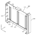
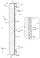
- FIG. 5 is a front view showing a configuration when the power storage element 100 is arranged in the spacer 200 according to the present embodiment. Specifically, FIG. 5 is a front view showing a configuration in which the power storage element 100, the spacer 200, and the side member 400 are assembled when viewed from the Y-axis minus direction side (side member 400 is a cross-sectional view). is there.
- FIG. 6 and 7 are cross-sectional views showing a configuration when the power storage element 100 is arranged in the spacer 200 according to the present embodiment.
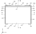
- FIG. 6 is a cross-sectional view showing a configuration when the configuration of FIG. 5 is cut along a plane parallel to the XY plane passing through the VI-VI line.
- the side member 400 is not shown.
- FIG. 7 is a cross-sectional view showing a configuration when the configuration of FIG. 5 is cut in a plane parallel to the YZ plane passing through the VII-VII line (the cutting position of the VII-VII line is the center in the X-axis direction of FIG. (Position of cutting at the second bulging portion 212b of the bulging portion 212).
- the spacer 200 has a spacer main body portion 210 and a spacer side wall portion 220.
- the spacer main body 210 is a rectangular and flat plate-shaped portion constituting the main body of the spacer 200, and is arranged parallel to the XZ plane. As described above, the spacer main body 210 is arranged in the Y-axis plus direction or the Y-axis minus direction of the power storage element 100. 5 to 7 show a state in which the spacer main body 210 is arranged in the Y-axis plus direction (one side of the first direction) of the power storage element 100.
- the spacer side wall portion 220 is a wall portion that is arranged so as to extend in the Z-axis direction at the end portion of the spacer 200 in the X-axis direction and is arranged so as to cover the end portion of the power storage element 100 in the X-axis direction.
- two spacer side wall portions 220 are arranged at both ends of the spacer 200 in the X-axis direction to cover both ends of the power storage element 100 in the X-axis direction.
- the two spacer side wall portions 220 include a pair of short side surface portions 122 of the container 110 of the power storage element 100, both ends of the lid 130 in the X-axis direction, and both ends of the bottom surface portion 123 in the X-axis direction. It is arranged so as to cover approximately half of the portion in the Y-axis direction.
- the spacer main body 210 has a flat plate portion 211, a bulging portion 212, and a protrusion 213.
- the bulging portion 212 is a bulging portion extending in the Z-axis plus direction (second direction intersecting the first direction) in the central portion of the spacer main body 210 in the Z-axis direction.
- the bulging portion 212 extends linearly in one direction (Z-axis direction).
- the bulging portion 212 does not extend to at least one end of the spacer 200 in the Z-axis direction (in the present embodiment, both ends in the Z-axis direction).
- a plurality of (specifically, three) bulging portions 212 are arranged apart from each other in the X-axis direction (third direction intersecting the first direction and the second direction). That is, between the flat plate portion 211 and the protrusion 213, three bulging portions 212 located at the central portion and both end portions in the X-axis direction are arranged so as to extend in the Z-axis direction.
- the bulging portion 212 has a shape that bulges in at least one of the Y-axis plus direction (one side in the first direction) and the Y-axis minus direction (the other side in the first direction).
- each bulging portion 212 bulges in both the Y-axis plus direction and the Y-axis minus direction, and is a pair of bulging portions as shown in FIGS. 6 and 7. It has a bulging portion 212a and a second bulging portion 212b.
- the bulging portion 212 in FIG. 7, the case of the second bulging portion 212b is shown) has a bulging portion side wall portion 212c at an end portion in the Z-axis direction.
- the bulging portion side wall portion 212c is a wall portion that continuously connects the bulging portion 212 to the upper and lower plate-shaped portions (flat plate portion 211 and the like).
- the bulging side wall portion 212c may be a portion parallel to the Y-axis direction, but in the present embodiment, the bulging portion side wall portion 212c is inclined with respect to the Y-axis direction. That is, the bulging portion 212 does not form a gap between the bulging portion 212 and the surrounding plate-shaped portion (flat plate portion 211 or the like) (without forming a through hole in the spacer main body portion 210), and the spacer main body portion 210 It is a part that swells from.
- the bulging portion 212 has a structure in which the end portion is closed, whereby the bulging portion 212 has rigidity and can appropriately hold the power storage element 100 when the power storage device 10 is used.
- the first bulging portion 212a is a portion that extends in the Z-axis plus direction (second direction) and bulges in the Y-axis plus direction (one side in the first direction).
- the first bulging portion 212a extends linearly in one direction (Z-axis direction). That is, the first bulging portion 212a is a bulging portion having a concavo-convex structure in which the surface on the minus direction side of the Y axis is recessed and the surface on the plus direction side of the Y axis is projected.
- the surface of the first bulging portion 212a on the Y-axis plus direction side is a flat surface (flat surface), and the first bulging portion 212a is the flat surface and is arranged on the Y-axis plus direction side of the spacer 200. It comes into contact with the long side surface portion 121 of the element 100. Since the first bulging portion 212a has a concavo-convex structure, a space is formed in the concave portion, so that the bulging side (Y-axis plus direction side) of the first bulging portion 212a when the power storage element 100 expands. ) Is pressed toward the space side (Y-axis minus direction side), and the expansion of the power storage element 100 can be absorbed. In FIGS. 6 and 7, the power storage element 100 arranged on the positive side of the Y-axis is not shown.
- the second bulging portion 212b is arranged adjacent to the first bulging portion 212a, extends in the Z-axis plus direction (second direction), and extends in the Y-axis minus direction (the other side of the first direction). It is a bulging part.
- the second bulging portion 212b extends linearly in one direction (Z-axis direction). That is, the second bulging portion 212b is a bulging portion having a concavo-convex structure in which the surface on the positive direction side of the Y axis is recessed and the surface on the negative direction side of the Y axis is projected.
- the surface of the second bulging portion 212b on the negative direction side of the Y axis is a flat surface (flat surface), and the second bulging portion 212b is the flat surface and is arranged on the negative side of the Y axis of the spacer 200. It comes into contact with the long side surface portion 121 of the element 100. Since the second bulging portion 212b has a concavo-convex structure, a space is formed in the concave portion, so that the bulging side (Y-axis minus direction side) of the second bulging portion 212b when the power storage element 100 expands. ) Is pressed toward the space side (Y-axis plus direction side), and the expansion of the power storage element 100 can be absorbed.
- the second bulging portion 212b is arranged on the X-axis negative direction side of the first bulging portion 212a.
- the second bulging portion 212b is arranged on the plus direction side of the X axis of the first bulging portion 212a.
- the positional relationship between the first bulging portion 212a and the second bulging portion 212b is not particularly limited, but in the bulging portions 212 located at both ends in the X-axis direction, as described above, the first bulging portion 212a and the second bulging portion 212a It is preferable that the second bulging portion 212b is arranged so that the positional relationship is symmetrical (reverse).
- the amount of protrusion of the first bulging portion 212a and the second bulging portion 212b is not particularly limited, but the amount of protrusion of the first bulging portion 212a in the Y-axis positive direction and the protruding amount of the second bulging portion 212b in the Y-axis negative direction.
- the amount of protrusion to is preferably the same.
- the flat plate portion 211 is a flat plate-shaped portion parallel to the XZ plane and arranged at the end of the spacer main body 210 on the Z-axis plus direction side so as to extend in the X-axis direction. That is, the flat plate portion 211 is arranged in the Z-axis plus direction (one side in the second direction) of the bulging portion 212. Specifically, the flat plate portion 211 is a long portion extending over the plurality of bulging portions 212 in the Z-axis plus direction (one side of the second direction) of the plurality of bulging portions 212. Is.
- the Z-axis minus direction side of the spacer main body 210 (Z-axis minus direction side of the plurality of bulging parts 212, Z-axis minus direction side of the protrusion 213) is also a flat plate-shaped part, and this part is defined as a flat plate part. You can also. This flat plate portion is reinforced by protrusions 213.
- the container protruding portion 110a of the power storage element 100 is arranged to face the flat plate portion 211. That is, the container projecting portion 110a is arranged so as to project toward the flat plate portion 211.
- the long side protruding portion 111 of the container protruding portion 110a is arranged in contact with the flat plate portion 211. Therefore, the amount of protrusion of the container protrusion 110a in the Y-axis direction (the amount of protrusion of the long side surface protrusion 111) is preferably the same as the amount of protrusion of the first bulge portion 212a and the second bulge portion 212b.
- the protrusion 213 is a long protrusion arranged so as to extend in the X-axis direction (third direction) at the end of the spacer main body 210 on the negative direction side of the Z-axis. That is, the protrusion 213 is arranged in the Z-axis minus direction (the other side of the second direction) of the bulging portion 212. Specifically, the protrusions 213 are arranged so as to extend across the plurality of bulging portions 212 in the Z-axis minus direction of the plurality of bulging portions 212.
- the protrusions 213 are arranged so as to extend from one end to the other end of the spacer main body 210 in the X-axis direction at opposite positions on both sides in the Y-axis direction of the spacer main body 210. ing.
- the protrusion 213 is arranged at a position corresponding to the container protrusion 110a of the power storage element 100. That is, the protrusion 213 is arranged parallel to the portion on the long side surface portion 121 side of the container protrusion 110a of the power storage element 100 and on the bottom surface side (Z-axis minus direction side) of the power storage element 100. As a result, the assembled state of the power storage element 100 and the spacer 200 becomes more stable.
- the tip surface (plane on the Y-axis direction side) of the protrusion 213 is a flat surface (flat surface), and the protrusion 213 is in contact with the long side surface portion 121 of the power storage element 100 on the flat surface. Therefore, the amount of protrusion of the protrusion 213 in the Y-axis direction is preferably the same as the amount of protrusion of the first bulging portion 212a and the second bulging portion 212b.
- the amount of protrusion of the protrusion 213 in the Y-axis direction is equal to the dimension in the Y-axis direction from the long side surface portion 121 of the power storage element 100 to the tip of the container protrusion 110a.
- the position of the main surface of the spacer main body 210 in the Y-axis direction is set to coincide with the position of the tip of the container protrusion 110a in the Y-axis direction.
- the main surface of the spacer main body 210 is a surface around the bulging portion 212 in the spacer main body 210, which is adjacent to the outer surface of the flat plate portion 211, the surface between the plurality of bulging portions 212, and the bulging portion 212. It can be paraphrased as a surface.
- the concept of "contact" between the spacer 200 and the power storage element 100 described above is not limited to the case where the spacer 200 and the power storage element 100 are in contact with each other, but also when a gap is usually formed, but when vibration or shock is applied from the outside, etc. It also includes the case of contacting with.
- the power storage element 100 does not have an active ventilation structure to the power storage element 100. This can be applied when the power storage element 100 generates less heat, or when the cooling medium is cooled by a cooling plate or the like that circulates inside. On the other hand, when a ventilation structure is provided for cooling the power storage element 100, the following may be performed.
- the space next to the bulging portion 212 can be a ventilation path communicating with the outside of the power storage device 10.
- the protrusion 213 may have a discontinuous shape that is partially interrupted instead of having a continuous shape as a whole, and the discontinuous portion may be used as a ventilation path.
- the side member 400 When the extending direction of the bulging portion 212 is parallel to the upper surface of the lid 130, an opening is provided in the spacer side wall portion 220, and the side member 400 is provided so that the space next to the bulging portion 212 is outside the power storage device 10.
- the shape may be such that they can communicate with each other.
- the side member 400 may be provided with an opening that communicates with the outside, or the side member 400 may be band-shaped (band-shaped) or rod-shaped (rod-shaped) instead of the plate-shaped as in the present embodiment. Good.
- the spacer 200 has a bulging portion 212 extending in the second direction (Z-axis direction) and a bulging portion 212 in the second direction. It has a flat plate portion 211 arranged on one side. In this way, by arranging the flat plate portion 211 in the extending direction (Z-axis direction) of the bulging portion 212 in the spacer 200, even if the bulging portion 212 is recessed, it intersects with the extending direction of the bulging portion 212.
- the flat plate portion 211 can suppress the spacer 200 from extending in the direction (X-axis direction). As a result, even when the power storage element 100 is swollen and the spacer 200 is pressed against the power storage element 100, the spacer 200 can be prevented from being deformed.
- the resin spacer 200 When the power storage element 100 swells, the resin spacer 200 tries to deform so as to stretch.
- the bulging portion 212 extends in the Z-axis direction, the spacer 200 tends to be deformed in the X-axis direction, but as shown in FIG. 5 and the like, both sides of the spacer 200 in the X-axis direction. Since the side member 400 is arranged (contacted) with the spacer 200, the deformation of the spacer 200 in the X-axis direction is restricted.
- the spacer 200 tends to deform in the Z-axis direction, but a part of the side members 400 on both sides of the spacer 200 in the Z-axis direction (FIG. Since only the protrusions 410 and 420) of 5 are arranged, the spacer 200 is easily deformed in the Z-axis direction.
- the protruding portion 410 is a portion provided at the end of the spacer 200 on the Z-axis positive direction side and projects toward the inside (the power storage element 100 side), and the protruding portion 420 is the Z-axis negative direction side of the spacer 200.
- the spacer 200 is more likely to be deformed in the Z-axis direction.
- the flat plate portion 211 can suppress the deformation of the spacer 200, but since the side member 400 is arranged (contacted) over the entire side surfaces of the spacer 200 on both sides in the X-axis direction. Deformation of the spacer 200 in the X-axis direction can be suppressed more effectively.
- the side member 400 does not abut over the entire side surface of the spacer 200 in the X-axis direction as in the present embodiment, but may abut a part of the side surface of the spacer 200.
- the side member 400 may not be a member that restrains the power storage element 100, but may be a side wall portion of an exterior body that houses the power storage element 100 or the like. That is, in the present embodiment, the following power storage device is also disclosed.
- This power storage device includes a spacer 200 having a bulging portion 212 extending in the Z-axis direction, and a side member 400 (the above-mentioned exterior body) arranged in contact with at least a part of the side surface of the spacer 200 in the X-axis direction.
- the bulging portion 212 may extend in the Z-axis direction to the end portion of the spacer main body portion 210.
- the bulging portion 212 bulges in one side of the first direction (Y-axis plus direction) and the first bulging portion 212a in the first direction (Y-axis minus direction). It has a second bulging portion 212b.
- the spacer 200 has a plurality of bulging portions 212 arranged side by side, and the flat plate portion 211 is arranged on one side of the plurality of bulging portions 212 in the second direction.
- the stress when the power storage element 100 swells can be dispersed to the plurality of bulging portions 212.
- the flat plate portion 211 is arranged on one side of the second direction of the plurality of bulging portions 212, the flat plate portion prevents the spacer 200 from extending even if each bulging portion 212 is recessed. 211 can be suppressed. As a result, it is possible to further suppress the deformation of the spacer 200.
- the spacer 200 Since the spacer 200 has bulging portions 212 at the center and both ends in the X-axis direction, the surface (long side surface portion 121) of the power storage element 100 is evenly pressed when the power storage element 100 is pressed. Can be done.
- the container protruding portion 110a is formed on the power storage element 100, the container protruding portion 110a is projected toward the flat plate portion 211 of the spacer 200. As a result, it is possible to prevent the container protrusion 110a of the power storage element 100 from interfering with the bulging portion 212 of the spacer 200, so that the container protruding portion 110a and the bulging portion 212 interfere with each other and the spacer 200 is deformed (damaged). Can be suppressed.
- the spacer 200 has a protrusion 213 extending in the third direction (X-axis direction) on the side of the bulging portion 212.
- the spacer 200 can be reinforced on the side of the bulging portion 212. As a result, the spacer 200 can be further suppressed from being deformed.
- the spacer 200 has three bulging portions 212 at the central portion and both end portions in the X-axis direction.
- the number of the bulging portions 212 is not particularly limited, and may be a plurality of bulging portions 212 other than three, or may be one.
- the bulging portions 212 are preferably arranged at equal intervals in the X-axis direction, but are not limited thereto.
- the bulging portion 212 is formed continuously in the Z-axis direction, so that the bulging portion 212 has a shape extending in the Z-axis direction.
- the bulging portion 212 may have a shape extending in the Z-axis direction by forming a plurality of bulging portions intermittently in the Z-axis direction.
- the bulging portion 212 is formed by arranging the first bulging portion 212a and the second bulging portion 212b in the X-axis direction.
- the bulging portion 212 may be formed by arranging the first bulging portion 212a and the second bulging portion 212b in the Z-axis direction.
- the bulging portion 212 may have a configuration in which the X-axis direction and the Z-axis direction are interchanged in the above embodiment. That is, the X-axis direction can be defined as the second direction, and the bulging portion 212 extends in the X-axis direction but does not extend to the X-axis direction end of the spacer main body 210, and the bulging portion 212 of the bulging portion 212.
- the flat plate portion is arranged on one side in the X-axis direction.
- the protrusions 213 will be extended in the Z-axis direction, and the protrusions 213 are preferably arranged on both sides of the spacer main body 210 in the X-axis direction.
- various modifications relating to the above-described embodiment can also be applied to the present modifications by exchanging the X-axis direction and the Z-axis direction.
- the bulging portion 212 has one first bulging portion 212a and one second bulging portion 212b as a pair of bulging portions.
- the bulging portion 212 may have any number of first bulging portions 212a and may have any number of second bulging portions 212b.
- the bulging portion 212 may have a different number of first bulging portions 212a and a second bulging portion 212b as a pair of bulging portions.
- the bulging portion 212 may have a plurality of pairs of the first bulging portion 212a and the second bulging portion 212b.
- the bulging portion 212 may have a configuration in which the first bulging portion 212a and the second bulging portion 212b are not paired but are randomly arranged.
- the bulging portion 212 does not have to have the first bulging portion 212a or the second bulging portion 212b (the first bulging portion 212a or the second bulging portion 212b has only one of them). May be). However, it is preferable that the bulging portion 212 has the same number of first bulging portions 212a and second bulging portions 212b.
- the protrusion 213 is arranged in the Z-axis minus direction of the bulging portion 212.
- the protrusion 213 may be arranged in the Z-axis plus direction of the bulging portion 212. That is, the protrusion 213 may be formed on the flat plate portion 211. In this way, the protrusion 213 is arranged so as to extend in the X-axis direction in the Z-axis plus direction (one side of the second direction) or the Z-axis minus direction (the other side of the second direction) of the bulging portion 212. I just need to be there.
- the protrusion 213 When the protrusion 213 is arranged in the Z-axis plus direction of the bulge 212, if the power storage element 100 has the container protrusion 110a as in the above embodiment, the protrusion 213 avoids the container protrusion 110a. It is preferable that the container is arranged at a vertical position (a position avoiding the inclined surface of the container protruding portion 110a).
- the protrusions 213 are arranged so as to extend from one end to the other end of the spacer main body 210 in the X-axis direction at opposite positions on both sides of the spacer main body 210. did.
- the protrusions 213 may be arranged at positions where both sides of the spacer main body 210 do not face each other, or may be arranged only on one side of the spacer main body 210.
- the length of the protrusions 213 is not particularly limited, and the protrusions 213 may have a shape extending in the X-axis direction by forming a plurality of protrusions intermittently in the X-axis direction. ..
- the spacer 200 does not have to have the protrusion 213.
- the power storage element 100 has a container protruding portion 110a arranged at the end on the Z-axis plus direction side of the container 110 as a protruding portion protruding toward the flat plate portion 211. ..
- the position and shape of the protruding portion of the power storage element 100 are not particularly limited.
- the power storage element 100 does not have to have a protruding portion.
- all spacers 200 have the above configuration. However, any spacer 200 may not have the above configuration. The same applies to the power storage element 100.
- the power storage device 10 does not need to include all the components shown in FIG.
- the power storage device 10 may not include the end member 300, the side member 400, the bus bar holding member 500, or the substrate 700.
- the scope of the present invention also includes a form constructed by arbitrarily combining the above-described embodiments and the components included in the above-described modification.
- the present invention can be realized not only as such a power storage device 10, but also as a spacer 200 included in the power storage device 10.
- the present invention can be applied to a power storage device or the like equipped with a power storage element such as a lithium ion secondary battery.
- Power storage device 100 Power storage element 110 Container 110a Container protrusion 111 Long side protrusion 112 Short side protrusion 120 Container body 121 Long side part 122 Short side part 123 Bottom part 130 Lid 131 Gas discharge valve 132 Lubrication part 140 Electrode terminal 150 Gasket 200 Spacer 210 Spacer body 211 Flat plate part 212 Swelling part 212a First bulging part 212b Second bulging part 212c Swelling part Side wall part 213 Protrusion 220 Spacer side wall part 300 End member 400 Side member 400a Joining member 500 Busbar Holding member 600 Busbar 610 External terminal 700 Board 710 Wiring
Abstract
蓄電装置(10)は、蓄電素子(100)と、蓄電素子(100)の第一方向の一方側に配置されるスペーサ(200)と、を備え、スペーサ(200)は、第一方向と交差する第二方向に延設され、かつ、第一方向の一方側及び第一方向の他方側の少なくとも一方に膨出する膨出部(212)と、膨出部(212)の第二方向の一方側に配置される平板部(211)と、を有する。
Description
本発明は、蓄電素子とスペーサとを備える蓄電装置に関する。
従来、蓄電素子とスペーサとを備える蓄電装置が広く知られている。特許文献1には、複数のバッテリセル(蓄電素子)がホルダ(スペーサ)を挟持した状態で積層されたバッテリモジュール(蓄電装置)が開示されている。
しかしながら、上記従来のような構成の蓄電装置では、スペーサが変形してしまうおそれがある。上記特許文献1に開示された蓄電装置(バッテリモジュール)では、スペーサ(ホルダ)は、蓄電素子(バッテリセル)との間に冷却風が流れる複数の冷却風通路を形成するために、本体部が波板状に折り曲げられている。このため、蓄電素子が膨れると、蓄電素子にスペーサが押圧され、その結果、スペーサが伸びるように変形する。本願発明者は、このように、上記従来のような構成の蓄電装置では、スペーサが変形してしまう(伸びてしまう)おそれがあることを見出した。
本発明は、スペーサが変形するのを抑制できる蓄電装置を提供することを目的とする。
本発明の一態様に係る蓄電装置は、蓄電素子と、前記蓄電素子の第一方向の一方側に配置されるスペーサと、を備え、前記スペーサは、前記第一方向と交差する第二方向に延設され、かつ、前記第一方向の一方側及び前記第一方向の他方側の少なくとも一方に膨出する膨出部と、前記膨出部の前記第二方向の一方側に配置される平板部と、を有する。
本発明は、このような蓄電装置として実現できるだけでなく、当該蓄電装置が備えるスペーサとしても実現できる。
本発明における蓄電装置によれば、スペーサが変形するのを抑制できる。
本発明の一態様に係る蓄電装置は、蓄電素子と、前記蓄電素子の第一方向の一方側に配置されるスペーサと、を備え、前記スペーサは、前記第一方向と交差する第二方向に延設され、かつ、前記第一方向の一方側及び前記第一方向の他方側の少なくとも一方に膨出する膨出部と、前記膨出部の前記第二方向の一方側に配置される平板部と、を有する。
これによれば、蓄電装置において、蓄電素子の第一方向の一方側に配置されるスペーサは、第二方向に延設される膨出部と、膨出部の第二方向の一方側に配置される平板部と、を有している。このように、スペーサにおいて、膨出部の延設方向に平板部を配置することで、膨出部が凹んでも、膨出部の延設方向と交差する方向にスペーサが伸びようとするのを平板部が抑制できる。これにより、蓄電素子が膨れて、蓄電素子にスペーサが押圧された場合でも、スペーサが変形するのを抑制できる。
前記膨出部は、前記第二方向に延設され、かつ、前記第一方向の一方側に膨出する第一膨出部と、前記第一膨出部に隣接して配置され、前記第二方向に延設され、かつ、前記第一方向の他方側に膨出する第二膨出部と、を有してもよい。
これによれば、スペーサにおいて、膨出部は、第一方向の一方側に膨出する第一膨出部と、第一方向の他方側に膨出する第二膨出部と、を有している。このように、スペーサの膨出部が両方向に膨出することで、当該膨出部によって、蓄電素子が膨れた際の応力をより緩和できる。これにより、蓄電素子が膨れた場合に、蓄電素子がスペーサを変形させる力を緩和できるため、スペーサが変形するのをより抑制できる。
前記スペーサは、前記第一方向及び前記第二方向と交差する第三方向において、離間して配置される複数の前記膨出部を有し、前記平板部は、前記複数の膨出部の前記第二方向の一方側に配置されてもよい。
これによれば、スペーサは、離間して並ぶ複数の膨出部を有しており、平板部は、複数の膨出部の第二方向の一方側に配置されている。このように、スペーサが、複数の膨出部を有しているため、蓄電素子が膨れた際の応力を複数の膨出部に分散させることができる。スペーサにおいて、平板部は、複数の膨出部の第二方向の一方側に配置されているため、それぞれの膨出部が凹んでも、スペーサが伸びようとするのを平板部が抑制できる。これらにより、スペーサが変形するのをより抑制できる。
前記蓄電素子は、前記平板部に向けて突出する突出部を有してもよい。
蓄電装置において、蓄電素子が突出部を有している場合がある。蓄電素子の容器の溶接を容易にしたり溶接強度を高くしたりするために、容器の溶接部分に突出部を形成して、溶接部分を厚くする場合がある。容器に電極体等の内容物を入れやすいように、容器本体の蓋体側に突出部を形成して、容器本体の開口を広げる場合もある。このように、蓄電素子に突出部を形成する場合、当該突出部をスペーサの平板部に向けて突出させる。これにより、蓄電素子の突出部とスペーサの膨出部とが干渉するのを抑制できるため、当該突出部と膨出部とが干渉してスペーサが変形(損傷)するのを抑制できる。
前記スペーサは、さらに、前記膨出部の前記第二方向の一方側または前記第二方向の他方側に配置され、かつ、前記第一方向及び前記第二方向と交差する第三方向に延設される突起を有してもよい。
これによれば、スペーサは、膨出部の側方に、第三方向に延設される突起を有している。このように、スペーサに突起を設けることで、膨出部の側方においてスペーサを補強できる。これにより、スペーサが変形するのをさらに抑制できる。
以下、図面を参照しながら、本発明の実施の形態(及びその変形例)に係る蓄電装置について説明する。以下で説明する実施の形態は、包括的または具体的な例を示すものである。以下の実施の形態で示される数値、形状、材料、構成要素、構成要素の配置位置及び接続形態、製造工程、製造工程の順序などは、一例であり、本発明を限定する主旨ではない。各図において、寸法等は厳密に図示したものではない。
以下の説明及び図面中において、1つの蓄電素子における一対の電極端子の並び方向、1つの蓄電素子の容器における一対の短側面の対向方向、一対のサイド部材の並び方向、または、蓄電素子とサイド部材との並び方向を、X軸方向と定義する。複数の蓄電素子の並び方向、複数のスペーサの並び方向、一対のエンド部材の並び方向、蓄電素子とスペーサとエンド部材との並び方向、1つの蓄電素子の容器における一対の長側面の対向方向、または、蓄電素子、スペーサ若しくはエンド部材の厚み方向を、Y軸方向と定義する。蓄電素子の容器本体と蓋との並び方向、蓄電素子とバスバー保持部材とバスバーとの並び方向、または、上下方向を、Z軸方向と定義する。これらX軸方向、Y軸方向及びZ軸方向は、互いに交差(本実施の形態では直交)する方向である。使用態様によってはZ軸方向が上下方向にならない場合も考えられるが、以下では説明の便宜のため、Z軸方向を上下方向として説明する。
以下の説明において、X軸プラス方向とは、各図におけるX軸の矢印方向を示し、X軸マイナス方向とは、X軸プラス方向とは反対方向を示す。Y軸方向及びZ軸方向についても同様である。さらに、以下では、Y軸方向を第一方向、Z軸方向を第二方向、X軸方向を第三方向とも呼ぶ場合がある。この場合、Y軸プラス方向を第一方向の一方側、Y軸マイナス方向を第一方向の他方側のように定義する。Z軸プラス方向を第二方向の一方側、Z軸マイナス方向を第二方向の他方側のように定義する。さらに、平行及び直交などの、相対的な方向または姿勢を示す表現は、厳密には、その方向または姿勢ではない場合も含む。2つの方向が直交している、とは、当該2つの方向が完全に直交していることを意味するだけでなく、実質的に直交していること、すなわち、例えば数%程度の差異を含むことも意味する。以下の実施の形態の説明では、図1に示される蓄電装置10を、Y軸プラス方向に向かって見た場合として説明する。
(実施の形態)
[1 蓄電装置10の全般的な説明]
まず、蓄電装置10の構成について、説明する。図1は、本実施の形態に係る蓄電装置10の外観を示す斜視図である。図2は、本実施の形態に係る蓄電装置10を分解した場合の各構成要素を示す分解斜視図である。
[1 蓄電装置10の全般的な説明]
まず、蓄電装置10の構成について、説明する。図1は、本実施の形態に係る蓄電装置10の外観を示す斜視図である。図2は、本実施の形態に係る蓄電装置10を分解した場合の各構成要素を示す分解斜視図である。
蓄電装置10は、外部からの電気を充電し、また外部へ電気を放電できる装置であり、本実施の形態では、略直方体形状を有している。蓄電装置10は、電力貯蔵用途または電源用途などに使用される電池モジュール(組電池)である。具体的には、蓄電装置10は、自動車、自動二輪車、ウォータークラフト、スノーモービル、農業機械、建設機械、または、電気鉄道用の鉄道車両等の移動体の駆動用またはエンジン始動用等のバッテリ等として用いられる。上記の自動車としては、電気自動車(EV)、ハイブリッド電気自動車(HEV)、プラグインハイブリッド電気自動車(PHEV)及びガソリン自動車が例示される。上記の電気鉄道用の鉄道車両としては、電車、モノレール及びリニアモーターカーが例示される。蓄電装置10は、家庭用または発電機用等に使用される定置用のバッテリ等としても用いることができる。
図1及び図2に示すように、蓄電装置10は、複数の蓄電素子100と、複数のスペーサ200と、一対のエンド部材300と、一対のサイド部材400と、バスバー保持部材500と、複数のバスバー600と、基板700と、を備えている。
蓄電素子100は、電気を充電し、また、電気を放電できる二次電池(単電池)であり、より具体的には、リチウムイオン二次電池などの非水電解質二次電池である。蓄電素子100は、扁平な直方体形状(角形)の形状を有しており、スペーサ200に隣接して配置されている。つまり、複数の蓄電素子100のそれぞれが、複数のスペーサ200のそれぞれと交互に配置され、Y軸方向に並べられている。本実施の形態では、12個の蓄電素子100のそれぞれを挟む位置に、13個のスペーサ200がそれぞれ配置されている。
蓄電素子100の個数は12個には限定されず、12個以外の複数個であってもよいし、1個でもよい。蓄電素子100の形状は、特に限定されず、直方体形状以外の多角柱形状、円柱形状、楕円柱形状、長円形柱形状等、どのような形状であってもよいし、ラミネート型の蓄電素子とすることもできる。蓄電素子100は、非水電解質二次電池には限定されず、非水電解質二次電池以外の二次電池であってもよいし、キャパシタであってもよい。蓄電素子100は、二次電池ではなく、使用者が充電をしなくても蓄えられている電気を使用できる一次電池であってもよい。さらに、蓄電素子100は、固体電解質を用いた電池であってもよい。この蓄電素子100の構成の詳細な説明については、後述する。
スペーサ200は、蓄電素子100のY軸プラス方向またはY軸マイナス方向に配置され、蓄電素子100と他の部材とを電気的に絶縁する矩形状かつ板状のスペーサである。具体的には、スペーサ200は、隣り合う2つの蓄電素子100の間、及び、端部の蓄電素子100とエンド部材300との間に配置され、当該2つの蓄電素子100の間、及び、端部の蓄電素子100とエンド部材300との間を絶縁する。本実施の形態では、12個の蓄電素子100に対応して13個のスペーサ200が配置されているが、蓄電素子100の個数が12個以外の場合には、スペーサ200の個数も蓄電素子100の個数に応じて変更される。
スペーサ200は、蓄電素子100の長側面(後述の長側面部121)に加え、蓄電素子100の短側面(後述の短側面部122)の正面側または背面側(Y軸マイナス方向側またはY軸プラス方向側)の略半分も、覆うように形成されている。つまり、スペーサ200の正面側または背面側の両面(Y軸方向の両面)には凹部が形成されており、当該凹部に上記の蓄電素子100の略半分が挿入される。このような構成により、蓄電素子100を挟む2つのスペーサ200が、蓄電素子100の短側面を覆うこととなるため、蓄電素子100とサイド部材400との間の電気的絶縁性を確保できている。
スペーサ200は、ポリカーボネート(PC)、ポリプロピレン(PP)、ポリエチレン(PE)、ポリフェニレンサルファイド樹脂(PPS)、ポリフェニレンエーテル(PPE(変性PPEを含む))、ポリエチレンテレフタラート(PET)、ポリエーテルエーテルケトン(PEEK)、テトラフルオロエチレン・パーフルオロアルキルビニルエーテル(PFA)、ポリテトラフルオロエチレン(PTFE)、ポリブチレンテレフタレート(PBT)、ポリエーテルサルフォン(PES)、ABS樹脂、及びそれらの複合材料等の絶縁性の樹脂材料等で形成されている。スペーサ200は、電気的絶縁性を有するものであれば樹脂以外の材料で形成されていてもよく、セラミック、または、マイカ片を集積し結合することで構成されるダンマ材等で形成されていてもよい。複数のスペーサ200の全てが同じ材質の材料で形成されていなくてもよい。スペーサ200の構成のさらに詳細な説明については、後述する。
エンド部材300及びサイド部材400は、複数の蓄電素子100の並び方向(Y軸方向)において、蓄電素子100を外方から圧迫する部材である。つまり、エンド部材300及びサイド部材400は、複数の蓄電素子100を当該並び方向の両側から挟み込むことで、複数の蓄電素子100に含まれるそれぞれの蓄電素子100を当該並び方向の両側から圧迫する。
具体的には、エンド部材300は、複数の蓄電素子100のY軸方向両側に配置され、複数の蓄電素子100を、当該複数の蓄電素子100の並び方向(Y軸方向)の両側から挟み込んで保持する扁平なブロック状のエンドプレート(挟持部材)である。エンド部材300は、強度確保の観点等から、アルミニウム、アルミニウム合金、ステンレス鋼、鉄、メッキ鋼板等の金属製(導電性)の材料等で形成されている。エンド部材300の材質は特に限定されず、例えば強度の高い絶縁性の材料で形成されていてもよいし、絶縁処理が施されていたりしていてもよい。エンド部材300は、ブロック状のエンドプレートではなく、板状のエンドプレート等であってもよい。
サイド部材400は、複数の蓄電素子100のX軸方向両側に配置され、両端がエンド部材300に取り付けられて、複数の蓄電素子100を拘束する長尺状かつ平板状のサイドプレート(拘束部材、拘束バー)である。つまり、サイド部材400は、複数の蓄電素子100及び複数のスペーサ200を跨ぐようにY軸方向に延設されて配置され、当該複数の蓄電素子100及び複数のスペーサ200に対して、これらの並び方向(Y軸方向)における拘束力を付与する。本実施の形態では、当該複数の蓄電素子100及び複数のスペーサ200のX軸方向両側方に、一対のサイド部材400が配置されている。当該一対のサイド部材400のそれぞれが、Y軸方向両端部において、一対のエンド部材300のX軸方向端部に取り付けられている。これにより、一対のサイド部材400は、当該複数の蓄電素子100及び複数のスペーサ200を、X軸方向の両側及びY軸方向の両側から挟み込んで拘束する。
サイド部材400は、Z軸方向に並ぶ複数の接合部材400aによって、エンド部材300に接合されている。本実施の形態では、接合部材400aは、サイド部材400を貫通してエンド部材300に締結されるボルトである。サイド部材400は、エンド部材300と同様に、強度確保の観点等から、アルミニウム、アルミニウム合金、ステンレス鋼、鉄、メッキ鋼板等の金属製(導電性)の材料等で形成されているが、強度の高い絶縁性の部材で形成されていてもよいし、絶縁処理が施されていたりしていてもよい。サイド部材400は、板状のサイドプレートではなく、ブロック状または棒状の部材等であってもよい。
バスバー保持部材500は、バスバー600及び基板700等を保持し、当該バスバー600等と他の部材との電気的な絶縁、及び、当該バスバー600等の位置規制を行うことができる板状部材(バスバープレート、バスバーフレーム)である。バスバー保持部材500は、PC、PP、PE等のスペーサ200と同様の絶縁性の樹脂材料等で形成されている。
バスバー600は、複数の蓄電素子100上に配置され、複数の蓄電素子100の電極端子(後述の電極端子140)同士を電気的に接続する導電性の板状部材である。本実施の形態では、複数のバスバー600を用いて、隣り合う蓄電素子100の電極端子のうちの正極端子と負極端子とを順に接続することで、複数の蓄電素子100を直列に接続している。端部に配置されるバスバー600には、蓄電装置10の端子である外部端子610(正極外部端子、負極外部端子)が接続されている。本実施の形態では、バスバー600と電極端子とはレーザー溶接で接続されている。また、バスバー600は、蓄電素子100の電圧等を検出すための配線の接続部も備えており、接続部はZ軸プラス方向に折り曲げられている。バスバー600は、銅、銅合金、アルミニウム、アルミニウム合金等の金属製の導電部材等で形成されている。蓄電素子100同士の接続形態は特に限定されず、いずれかの蓄電素子100が並列接続されていてもよい。バスバー600と電極端子との接続方法は、レーザー溶接以外の溶接でもよいし、電極端子の形状に合わせてネジ締結等であってもよい。
基板700は、バスバー保持部材500に載置される回路基板であり、蓄電素子100の充電状態または放電状態を監視するための電子部品、ヒューズ、リレー、シャント抵抗、コネクタ等が配置されている。基板700には、コネクタを介して、配線710が接続されている。本実施の形態では、蓄電装置10のY軸プラス方向の端部において、配線710が集束されて基板700に接続されている。配線710は、蓄電素子100の電圧計測用の配線、及び、温度計測用の配線等を有しており、配線の一端はバスバー600の接続部に接続されている。
[2 蓄電素子100の構成の説明]
次に、蓄電素子100の構成について、詳細に説明する。図3は、本実施の形態に係る蓄電素子100の構成を示す斜視図である。
次に、蓄電素子100の構成について、詳細に説明する。図3は、本実施の形態に係る蓄電素子100の構成を示す斜視図である。
図3に示すように、蓄電素子100は、容器110と、一対の電極端子140(正極端子及び負極端子)と、一対のガスケット150と、を備えている。容器110の内方には、電極体、集電体(正極集電体及び負極集電体)、及び電解液(非水電解質)等が収容されているが、これらの図示は省略する。当該電解液としては、蓄電素子100の性能を損なうものでなければその種類に特に制限はなく、様々なものを選択できる。集電体の側方等にスペーサが配置されていてもよいし、容器110の外面を覆う絶縁シートが配置されていてもよい。
容器110は、開口が形成された容器本体120と、容器本体120の開口を閉塞する蓋体130とを有する直方体形状(角形)の容器である。容器本体120は、容器110の本体部を構成する矩形筒状で底を備える部材であり、Y軸方向両側の側面に一対の長側面部121を有し、X軸方向両側の側面に一対の短側面部122を有し、Z軸マイナス方向側に底面部123を有している。短側面部122は、一対の長側面部121及び底面部123に隣接し、長側面部121よりも面積が小さい矩形状の平面である。底面部123は、一対の長側面部121及び一対の短側面部122に隣接する矩形状の平面である。長側面部121は、一対の短側面部122及び底面部123に隣接し、短側面部122よりも面積が大きい矩形状の平面である。蓋体130は、容器110の蓋部を構成する矩形状の板状部材であり、容器本体120のZ軸プラス方向側に配置されている。蓋体130には、容器110内方の圧力が上昇した場合に当該圧力を開放するガス排出弁131、及び、容器110内方に電解液を注液するための注液部132等も設けられている。
このような構成により、容器110は、電極体等を容器本体120の内方に収容後、容器本体120と蓋体130とが溶接等によって接合されることにより、内部が密封される構造となっている。容器110(容器本体120及び蓋体130)の材質は、特に限定されないが、例えばステンレス鋼、アルミニウム、アルミニウム合金、鉄、メッキ鋼板など溶接可能(接合可能)な金属であるのが好ましい。
さらに、容器110は、外方に突出する容器突出部110aを有している。容器突出部110aは、蓋体130及び容器本体120の蓋体130側(Z軸プラス方向側)の端部の全周に亘って形成された突出部分である。つまり、容器突出部110aは、一対の長側面部121のZ軸プラス方向側の端部に一対の長側面突出部111を有し、一対の短側面部122のZ軸プラス方向側の端部に一対の短側面突出部112を有している。一対の長側面突出部111は、X軸方向に延設され、かつ、Z軸プラス方向に向かうほどY軸方向に徐々に広がる(Z軸方向に対して傾斜した)形状を有している。一対の短側面部122は、Y軸方向に延設され、かつ、Z軸プラス方向に向かうほどX軸方向に徐々に広がる(Z軸方向に対して傾斜した)形状を有している。このように、容器突出部110aは、一対の長側面突出部111、一対の短側面突出部112及び蓋体130の外周部分とで形成された、Z軸プラス方向に向かうほど、外方に徐々に突出するテーパ形状の部位である。
このような容器突出部110aは、以下の理由により、容器110に形成される。容器本体120と蓋体130との溶接部分を厚くして、容器本体120と蓋体130との溶接を容易にできるようにしたり溶接強度を高くしたりするために、容器本体120の蓋体130側の端部に容器突出部110aを形成する場合がある。容器本体120の開口を広げて、容器本体120に電極体等の内容物を入れやすいように、容器本体120の蓋体130側の端部に容器突出部110aを形成する場合がある。容器110を他の部材に対して位置決めするために、当該他の部材と係合または嵌合等させるための容器突出部110aを形成する場合がある。この場合、容器110は容器本体120の中央部が膨れやすいため、膨れにくい容器本体120の端部(本実施の形態では、蓋体130側の端部)に容器突出部110aを形成するのが好ましい。
電極端子140は、容器110の蓋体130に配置される蓄電素子100の端子(正極端子及び負極端子)であり、集電体を介して、電極体の正極板及び負極板に電気的に接続されている。つまり、電極端子140は、電極体に蓄えられている電気を蓄電素子100の外部空間に導出し、電極体に電気を蓄えるために蓄電素子100の内部空間に電気を導入するための金属製の部材である。電極端子140は、容器110の蓋体130から、Z軸プラス方向に突出して配置されている。電極端子140は、バスバー600と溶接されるために平板状となっているが、ネジ締結できるようにボルト端子を備えていてもよい。電極端子140は、アルミニウム、アルミニウム合金、銅、銅合金などで形成されている。
ガスケット150は、電極端子140と蓋体130との間、及び、蓋体130と集電体との間に配置され、電極端子140と蓋体130との間、及び、蓋体130と集電体との間の電気的な絶縁性及び気密性を確保するための部材である。ガスケット150は、PP、PE、PPS、PET、PEEK、PFA、PTFE、PBT、PES、ABS樹脂などの絶縁性の材料等で形成されている。
電極体は、正極板と負極板とセパレータとが積層されて形成された蓄電要素(発電要素)である。ここで、電極体が有する正極板は、アルミニウムまたはアルミニウム合金などの金属からなる長尺帯状の集電箔である正極基材層上に正極活物質層が形成されたものである。負極板は、銅または銅合金などの金属からなる長尺帯状の集電箔である負極基材層上に負極活物質層が形成されたものである。正極活物質層に用いられる正極活物質、負極活物質層に用いられる負極活物質としては、リチウムイオンを吸蔵放出可能なものであれば、適宜公知の材料を使用できる。集電体は、電極端子140と電極体とに電気的に接続される導電性と剛性とを備えた部材(正極集電体及び負極集電体)である。正極集電体は、正極板の正極基材層と同様、アルミニウムまたはアルミニウム合金などで形成され、負極集電体は、負極板の負極基材層と同様、銅または銅合金などで形成されている。
[3 スペーサ200の構成の説明]
次に、スペーサ200の構成について、詳細に説明する。図4は、本実施の形態に係るスペーサ200の構成を示す斜視図である。具体的には、図4は、図2に示したスペーサ200の構成を拡大して示す斜視図である。図5は、本実施の形態に係るスペーサ200に蓄電素子100を配置した場合の構成を示す正面図である。具体的には、図5は、蓄電素子100とスペーサ200とサイド部材400とを組み付けた状態を、Y軸マイナス方向側から見た場合の構成を示す正面図(サイド部材400は断面図)である。図6及び図7は、本実施の形態に係るスペーサ200に蓄電素子100を配置した場合の構成を示す断面図である。具体的には、図6は、図5の構成を、VI-VI線を通るXY平面に平行な面で切断した場合の構成を示す断面図である。図6では、サイド部材400の図示を省略している。図7は、図5の構成を、VII-VII線を通るYZ平面に平行な面で切断した場合の構成を示す断面図(VII-VII線の切断位置は、図6のX軸方向中央の膨出部212の第二膨出部212bで切断する位置)である。
次に、スペーサ200の構成について、詳細に説明する。図4は、本実施の形態に係るスペーサ200の構成を示す斜視図である。具体的には、図4は、図2に示したスペーサ200の構成を拡大して示す斜視図である。図5は、本実施の形態に係るスペーサ200に蓄電素子100を配置した場合の構成を示す正面図である。具体的には、図5は、蓄電素子100とスペーサ200とサイド部材400とを組み付けた状態を、Y軸マイナス方向側から見た場合の構成を示す正面図(サイド部材400は断面図)である。図6及び図7は、本実施の形態に係るスペーサ200に蓄電素子100を配置した場合の構成を示す断面図である。具体的には、図6は、図5の構成を、VI-VI線を通るXY平面に平行な面で切断した場合の構成を示す断面図である。図6では、サイド部材400の図示を省略している。図7は、図5の構成を、VII-VII線を通るYZ平面に平行な面で切断した場合の構成を示す断面図(VII-VII線の切断位置は、図6のX軸方向中央の膨出部212の第二膨出部212bで切断する位置)である。
これらの図に示すように、スペーサ200は、スペーサ本体部210と、スペーサ側壁部220と、を有している。スペーサ本体部210は、スペーサ200の本体を構成する矩形状かつ平板状の部位であり、XZ平面に平行に配置されている。上述の通り、スペーサ本体部210は、蓄電素子100のY軸プラス方向またはY軸マイナス方向に配置される。図5~図7では、スペーサ本体部210が蓄電素子100のY軸プラス方向(第一方向の一方側)に配置されている状態を図示している。
スペーサ側壁部220は、スペーサ200のX軸方向の端部にZ軸方向に延設されて配置され、蓄電素子100のX軸方向の端部を覆うように配置された壁部である。本実施の形態では、スペーサ200のX軸方向の両端部に2つのスペーサ側壁部220が配置されて、蓄電素子100のX軸方向の両端部を覆っている。具体的には、当該2つのスペーサ側壁部220は、蓄電素子100の容器110の一対の短側面部122と、蓋体130のX軸方向の両端部と、底面部123のX軸方向の両端部とのY軸方向における略半分を覆うように配置される。
次に、スペーサ本体部210の構成について、さらに詳細に説明する。スペーサ本体部210は、平板部211と、膨出部212と、突起213と、を有している。
まず、膨出部212の構成について、詳細に説明する。膨出部212は、スペーサ本体部210のZ軸方向中央部において、Z軸プラス方向(第一方向と交差する第二方向)に延設された、膨出状の部位である。膨出部212は、一方向(Z軸方向)に直線状に延設されている。膨出部212は、スペーサ200におけるZ軸方向の少なくとも一方の端部(本実施の形態では、Z軸方向の双方の端部)までは延設されていない。本実施の形態では、X軸方向(第一方向及び第二方向と交差する第三方向)において、複数(具体的には、3つ)の膨出部212が離間して配置されている。つまり、平板部211と突起213との間に、X軸方向の中央部及び両端部に位置する3つの膨出部212が、Z軸方向に延設されて配置されている。
具体的には、膨出部212は、Y軸プラス方向(第一方向の一方側)及びY軸マイナス方向(第一方向の他方側)の少なくとも一方に膨出した形状を有している。本実施の形態では、それぞれの膨出部212は、Y軸プラス方向及びY軸マイナス方向の双方に膨出しており、図6及び図7に示すように、一対の膨出部である第一膨出部212a及び第二膨出部212bを有している。図7に示すように、膨出部212(図7では第二膨出部212bの場合を図示)は、Z軸方向の端部に、膨出部側壁部212cを有している。膨出部側壁部212cは、膨出部212を、その上下の板状部位(平板部211等)に連続的に繋ぐ壁部である。膨出部側壁部212cは、Y軸方向に平行な部位でもよいが、本実施の形態ではY軸方向に対して傾斜している。つまり、膨出部212は、周囲の板状部位(平板部211等)との間に空隙が形成されることなく(スペーサ本体部210に貫通孔が形成されることなく)、スペーサ本体部210から膨出した部位である。このように、膨出部212は、端部が閉じた構造であり、これによって剛性を有し、蓄電装置10の使用時に蓄電素子100を適切に保持できる。
第一膨出部212aは、Z軸プラス方向(第二方向)に延設され、かつ、Y軸プラス方向(第一方向の一方側)に膨出する部位である。第一膨出部212aは、一方向(Z軸方向)に直線状に延設されている。つまり、第一膨出部212aは、Y軸マイナス方向側の面が凹み、Y軸プラス方向側の面が突出した凹凸構造を有する膨出状の部位である。第一膨出部212aのY軸プラス方向側の面は平面(平坦面)となっており、第一膨出部212aは、当該平面で、スペーサ200のY軸プラス方向側に配置される蓄電素子100の長側面部121と当接する。第一膨出部212aが凹凸構造を有していることにより、凹部の方に空間が形成されるため、蓄電素子100の膨張時に第一膨出部212aの膨出側(Y軸プラス方向側)の面が当該空間側(Y軸マイナス方向側)に押圧されて、蓄電素子100の膨張を吸収できる。図6及び図7では、Y軸プラス方向側に配置される蓄電素子100は、不図示となっている。
第二膨出部212bは、第一膨出部212aに隣接して配置され、Z軸プラス方向(第二方向)に延設され、かつ、Y軸マイナス方向(第一方向の他方側)に膨出する部位である。第二膨出部212bは、一方向(Z軸方向)に直線状に延設されている。つまり、第二膨出部212bは、Y軸プラス方向側の面が凹み、Y軸マイナス方向側の面が突出した凹凸構造を有する膨出状の部位である。第二膨出部212bのY軸マイナス方向側の面は平面(平坦面)となっており、第二膨出部212bは、当該平面で、スペーサ200のY軸マイナス方向側に配置される蓄電素子100の長側面部121と当接する。第二膨出部212bが凹凸構造を有していることにより、凹部の方に空間が形成されるため、蓄電素子100の膨張時に第二膨出部212bの膨出側(Y軸マイナス方向側)の面が当該空間側(Y軸プラス方向側)に押圧されて、蓄電素子100の膨張を吸収できる。
X軸方向の中央部及びX軸プラス方向側の端部に位置する膨出部212は、第一膨出部212aのX軸マイナス方向側に第二膨出部212bが配置されている。これに対し、X軸マイナス方向側の端部に位置する膨出部212は、第一膨出部212aのX軸プラス方向側に第二膨出部212bが配置されている。第一膨出部212a及び第二膨出部212bの位置関係は特に限定されないが、X軸方向の両端部に位置する膨出部212においては、上述のように、第一膨出部212a及び第二膨出部212bの位置関係が対称(逆)になるように配置されているのが好ましい。第一膨出部212a及び第二膨出部212bの突出量は特に限定されないが、第一膨出部212aのY軸プラス方向への突出量と、第二膨出部212bのY軸マイナス方向への突出量とは、同じであるのが好ましい。
平板部211は、スペーサ本体部210のZ軸プラス方向側の端部にX軸方向に延設されて配置された、XZ平面に平行な平板状の部位である。つまり、平板部211は、膨出部212のZ軸プラス方向(第二方向の一方側)に配置されている。具体的には、平板部211は、複数の膨出部212のZ軸プラス方向(第二方向の一方側)に、当該複数の膨出部212に跨って延設された長尺状の部位である。スペーサ本体部210のZ軸マイナス方向側(複数の膨出部212のZ軸マイナス方向側、突起213のZ軸マイナス方向側)も平板状の部位であり、この部分を平板部と定義することもできる。この平板部は、突起213によって補強されている。
図7に示すように、平板部211には、蓄電素子100の容器突出部110aが対向して配置される。つまり、容器突出部110aは、平板部211に向けて突出して配置される。具体的には、容器突出部110aの長側面突出部111が、平板部211に当接して配置される。このため、容器突出部110aのY軸方向における突出量(長側面突出部111の突出量)は、第一膨出部212a及び第二膨出部212bの突出量と同じであるのが好ましい。
突起213は、スペーサ本体部210のZ軸マイナス方向側の端部にX軸方向(第三方向)に延設されて配置された、長尺状の突起である。つまり、突起213は、膨出部212のZ軸マイナス方向(第二方向の他方側)に配置されている。具体的には、突起213は、複数の膨出部212のZ軸マイナス方向に、当該複数の膨出部212に跨って延設されて配置されている。本実施の形態では、突起213は、スペーサ本体部210のY軸方向における両面の対向する位置に、スペーサ本体部210のX軸方向における一端から他端までに亘って、延設されて配置されている。突起213は、蓄電素子100の容器突出部110aに対応する位置に配置されている。つまり、突起213は、蓄電素子100の容器突出部110aの長側面部121側の部位に平行、かつ、蓄電素子100の底面側(Z軸マイナス方向側)に配置されている。これにより、蓄電素子100とスペーサ200との組付け状態がより安定する。
突起213の先端面(Y軸方向側の面)は平面(平坦面)となっており、突起213は、当該平面で、蓄電素子100の長側面部121と当接する。このため、突起213のY軸方向における突出量は、第一膨出部212a及び第二膨出部212bの突出量と同じであるのが好ましい。突起213のY軸方向における突出量は、蓄電素子100の長側面部121から容器突出部110a先端までのY軸方向の寸法に等しい。言い換えると、スペーサ本体部210の主面のY軸方向の位置は、容器突出部110aのY軸方向の先端位置と一致するように設定されている。スペーサ本体部210の主面とは、スペーサ本体部210における膨出部212の周囲の面であり、平板部211の外面、複数の膨出部212の間の面、膨出部212と隣接する面等と言い換えることができる。
上述のスペーサ200と蓄電素子100とが「当接する」の概念には、常に当接している場合だけではなく、通常は隙間が形成されているが、外部から振動または衝撃が加えられた場合等に当接する場合も含まれる。
本実施の形態では、蓄電素子100への積極的な通風構造は有していない。これは、蓄電素子100の発熱が少ない場合や、冷却媒体を内部に流通させる冷却プレート等で冷却する場合に適用できる。一方、蓄電素子100の冷却として通風構造を備える場合は、次のようにすればよい。
スペーサ200が膨出部212と平板部211とを有する構成であれば、膨出部212の隣の空間が蓄電装置10の外部と連通する通風路となり得る。スペーサ200が突起213を備える構成では、突起213を、全体的に連続した形状とせずに一部で途切れる不連続形状とし、不連続部分を通風経路とすればよい。膨出部212の延設方向が蓄電素子100の蓋体130の上面と交差する方向(本実施の形態ではZ軸方向)である場合、蓄電素子100への通風路という観点からは、蓄電素子100は容器突出部110aを有さなくてもよい。膨出部212の延設方向が蓋体130の上面と平行な場合は、スペーサ側壁部220に開口を設けるとともに、サイド部材400を、膨出部212の隣の空間が蓄電装置10の外部に連通するような形状とすればよい。具体的には、サイド部材400に、外部に連通する開口を設けたり、サイド部材400を、本実施の形態のようなプレート状ではなくバンド状(帯状)やロッド状(棒状)としたりすればよい。
[4 効果の説明]
以上のように、本実施の形態に係る蓄電装置10によれば、スペーサ200は、第二方向(Z軸方向)に延設される膨出部212と、膨出部212の第二方向の一方側に配置される平板部211と、を有している。このように、スペーサ200において、膨出部212の延設方向(Z軸方向)に平板部211を配置することで、膨出部212が凹んでも、膨出部212の延設方向と交差する方向(X軸方向)にスペーサ200が伸びようとするのを平板部211が抑制できる。これにより、蓄電素子100が膨れて、蓄電素子100にスペーサ200が押圧された場合でも、スペーサ200が変形するのを抑制できる。
以上のように、本実施の形態に係る蓄電装置10によれば、スペーサ200は、第二方向(Z軸方向)に延設される膨出部212と、膨出部212の第二方向の一方側に配置される平板部211と、を有している。このように、スペーサ200において、膨出部212の延設方向(Z軸方向)に平板部211を配置することで、膨出部212が凹んでも、膨出部212の延設方向と交差する方向(X軸方向)にスペーサ200が伸びようとするのを平板部211が抑制できる。これにより、蓄電素子100が膨れて、蓄電素子100にスペーサ200が押圧された場合でも、スペーサ200が変形するのを抑制できる。
蓄電素子100が膨れた場合、樹脂製のスペーサ200は伸びるように変形しようとする。本実施の形態では、膨出部212はZ軸方向に延設されているため、スペーサ200はX軸方向に変形しようとするが、図5等に示すように、スペーサ200のX軸方向両側にはサイド部材400が配置(当接)されているため、スペーサ200のX軸方向への変形が規制される。これに対し、膨出部212がX軸方向に延設されていると、スペーサ200がZ軸方向に変形しようとするが、スペーサ200のZ軸方向両側にはサイド部材400の一部(図5の突出部410及び420)しか配置されていないため、スペーサ200がZ軸方向に変形しやすい。突出部410は、スペーサ200のZ軸プラス方向側の端部に設けられた、内側(蓄電素子100側)に向けて突出する部位であり、突出部420は、スペーサ200のZ軸マイナス方向側の端部に設けられた、内側(蓄電素子100側)に向けて突出する部位である。サイド部材400が突出部410及び420を有していない場合には、スペーサ200がZ軸方向にさらに変形しやすくなる。このように、本実施の形態では、平板部211によってスペーサ200の変形を抑制できるが、サイド部材400がスペーサ200のX軸方向両側の側面全体に亘って配置(当接)されているため、スペーサ200のX軸方向への変形をさらに効果的に抑制できる。
サイド部材400は、本実施の形態のようにスペーサ200のX軸方向の側面全体に亘って当接するものでなく、スペーサ200の当該側面の一部に当接するものでもよい。サイド部材400は、蓄電素子100を拘束する部材ではなく、蓄電素子100を収容する外装体の側壁部等であってもよい。つまり、本実施の形態においては、以下の蓄電装置も開示している。この蓄電装置は、Z軸方向に延設される膨出部212を有するスペーサ200と、スペーサ200のX軸方向の側面の少なくとも一部に当接して配置されるサイド部材400(上述した外装体の側壁部等でもよい)と、を備えている。スペーサ200については、平板部211の有無は問わず、膨出部212はスペーサ本体部210の端部までZ軸方向に延設されていてもよい。
スペーサ200において、膨出部212は、第一方向の一方側(Y軸プラス方向)に膨出する第一膨出部212aと、第一方向の他方側(Y軸マイナス方向)に膨出する第二膨出部212bと、を有している。このように、スペーサ200の膨出部212が両方向に膨出することで、膨出部212によって、蓄電素子100が膨れた際の応力をより緩和できる。これにより、蓄電素子100が膨れた場合に、蓄電素子100がスペーサ200を変形させる力を緩和できるため、スペーサ200が変形するのをより抑制できる。
スペーサ200は、離間して並ぶ複数の膨出部212を有しており、平板部211は、複数の膨出部212の第二方向の一方側に配置されている。このように、スペーサ200が、複数の膨出部212を有しているため、蓄電素子100が膨れた際の応力を複数の膨出部212に分散させることができる。スペーサ200において、平板部211は、複数の膨出部212の第二方向の一方側に配置されているため、それぞれの膨出部212が凹んでも、スペーサ200が伸びようとするのを平板部211が抑制できる。これらにより、スペーサ200が変形するのをより抑制できる。
スペーサ200は、X軸方向の中央部及び両端部に膨出部212を有していることにより、蓄電素子100を圧迫する際に蓄電素子100の面(長側面部121)を均等に押さえることができる。
蓄電素子100に容器突出部110aが形成されているため、容器突出部110aをスペーサ200の平板部211に向けて突出させる。これにより、蓄電素子100の容器突出部110aとスペーサ200の膨出部212とが干渉するのを抑制できるため、容器突出部110aと膨出部212とが干渉してスペーサ200が変形(損傷)するのを抑制できる。
スペーサ200は、膨出部212の側方に、第三方向(X軸方向)に延設される突起213を有している。このように、スペーサ200に突起213を設けることで、膨出部212の側方においてスペーサ200を補強できる。これにより、スペーサ200が変形するのをさらに抑制できる。
[5 変形例の説明]
以上、本発明の実施の形態に係る蓄電装置10について説明したが、本発明は、この実施の形態に限定されるものではない。つまり、今回開示された実施の形態は、全ての点で例示であって制限的なものではなく、本発明の範囲は、請求の範囲によって示され、請求の範囲と均等の意味及び範囲内での全ての変更が含まれる。
以上、本発明の実施の形態に係る蓄電装置10について説明したが、本発明は、この実施の形態に限定されるものではない。つまり、今回開示された実施の形態は、全ての点で例示であって制限的なものではなく、本発明の範囲は、請求の範囲によって示され、請求の範囲と均等の意味及び範囲内での全ての変更が含まれる。
上記実施の形態では、スペーサ200は、X軸方向の中央部及び両端部に3つの膨出部212を有していることとした。しかし、膨出部212の数は特に限定されず、3つ以外の複数でもよいし、1つでもよい。膨出部212の配置位置は、X軸方向に等間隔で配置されているのが好ましいが、それには限定されない。
上記実施の形態では、膨出部212は、Z軸方向に連続的に形成されることで、Z軸方向に延設された形状となっていることとした。しかし、膨出部212は、Z軸方向に断続的に複数の膨出部が形成されることにより、Z軸方向に延設された形状となっていてもよい。
上記実施の形態では、膨出部212は、第一膨出部212aと第二膨出部212bとがX軸方向に並べられて形成されていることとした。しかし、膨出部212は、第一膨出部212aと第二膨出部212bとがZ軸方向に並べられて形成されていてもよい。例えば、膨出部212は、上記実施の形態において、X軸方向とZ軸方向とを入れ替えた構成となってもよい。つまり、X軸方向を第二方向と定義でき、膨出部212は、X軸方向に延設されるがスペーサ本体部210のX軸方向端部までは延設されず、膨出部212のX軸方向の一方側に平板部が配置されることとなる。突起213は、Z軸方向に延設されることとなるが、突起213は、スペーサ本体部210のX軸方向の両側に配置することが好ましい。その他、上記実施の形態に関する種々の変形例についても、X軸方向とZ軸方向とを入れ替えることで、本変形例に適用可能である。
上記実施の形態では、膨出部212は、一対の膨出部として1つの第一膨出部212aと1つの第二膨出部212bとを有していることとした。しかし、膨出部212は、いくつの第一膨出部212aを有していてもよいし、いくつの第二膨出部212bを有していてもよい。例えば、膨出部212は、一対の膨出部として、異なる数の第一膨出部212a及び第二膨出部212bを有していてもよい。膨出部212は、第一膨出部212a及び第二膨出部212bを複数対有していてもよい。膨出部212は、第一膨出部212a及び第二膨出部212bが対ではなく、ランダムに配置される構成でもよい。膨出部212は、第一膨出部212aまたは第二膨出部212bを有していなくてもよい(第一膨出部212aまたは第二膨出部212bが、いずれか1つのみある形態でもよい)。ただし、膨出部212は、同じ数の第一膨出部212a及び第二膨出部212bを有しているのが好ましい。
上記実施の形態では、スペーサ200において、突起213は、膨出部212のZ軸マイナス方向に配置されていることとした。しかし、突起213は、膨出部212のZ軸プラス方向に配置されていてもよい。つまり、突起213は、平板部211に形成されていてもよい。このように、突起213は、膨出部212のZ軸プラス方向(第二方向の一方側)またはZ軸マイナス方向(第二方向の他方側)に、X軸方向に延設されて配置されていればよい。突起213が膨出部212のZ軸プラス方向に配置される場合、上記実施の形態のように蓄電素子100が容器突出部110aを有していれば、突起213は、容器突出部110aを避けた位置(容器突出部110aの傾斜面を避けた位置)に配置されるのが好ましい。
上記実施の形態では、突起213は、スペーサ本体部210の両面の対向する位置に、スペーサ本体部210のX軸方向における一端から他端までに亘って、延設されて配置されていることとした。しかし、突起213は、スペーサ本体部210の両面の対向しない位置に配置されていてもよいし、スペーサ本体部210の片面にしか配置されていなくてもよい。突起213は、延設される長さは特に限定されず、さらに、X軸方向に断続的に複数の突起が形成されることにより、X軸方向に延設された形状となっていてもよい。スペーサ200は、突起213を有していなくてもよい。
上記実施の形態では、蓄電素子100は、平板部211に向けて突出する突出部として、容器110のZ軸プラス方向側の端部に配置される容器突出部110aを有していることとした。しかし、蓄電素子100が有する突出部の位置及び形状は特に限定されない。蓄電素子100は、突出部を有していなくてもよい。
上記実施の形態では、全てのスペーサ200が、上記の構成を有していることとした。しかし、いずれかのスペーサ200が、上記の構成を有していないことにしてもよい。蓄電素子100についても同様である。
上記実施の形態において、蓄電装置10は、図2に示した構成要素を全て備えている必要はない。蓄電装置10は、エンド部材300、サイド部材400、バスバー保持部材500または基板700を備えていなくてもよい。
上記実施の形態及び上記変形例が備える各構成要素を任意に組み合わせて構築される形態も、本発明の範囲内に含まれる。
本発明は、このような蓄電装置10として実現できるだけでなく、蓄電装置10が備えるスペーサ200としても実現できる。
本発明は、リチウムイオン二次電池などの蓄電素子を備えた蓄電装置等に適用できる。
10 蓄電装置
100 蓄電素子
110 容器
110a 容器突出部
111 長側面突出部
112 短側面突出部
120 容器本体
121 長側面部
122 短側面部
123 底面部
130 蓋体
131 ガス排出弁
132 注液部
140 電極端子
150 ガスケット
200 スペーサ
210 スペーサ本体部
211 平板部
212 膨出部
212a 第一膨出部
212b 第二膨出部
212c 膨出部側壁部
213 突起
220 スペーサ側壁部
300 エンド部材
400 サイド部材
400a 接合部材
500 バスバー保持部材
600 バスバー
610 外部端子
700 基板
710 配線
100 蓄電素子
110 容器
110a 容器突出部
111 長側面突出部
112 短側面突出部
120 容器本体
121 長側面部
122 短側面部
123 底面部
130 蓋体
131 ガス排出弁
132 注液部
140 電極端子
150 ガスケット
200 スペーサ
210 スペーサ本体部
211 平板部
212 膨出部
212a 第一膨出部
212b 第二膨出部
212c 膨出部側壁部
213 突起
220 スペーサ側壁部
300 エンド部材
400 サイド部材
400a 接合部材
500 バスバー保持部材
600 バスバー
610 外部端子
700 基板
710 配線
Claims (5)
- 蓄電素子と、
前記蓄電素子の第一方向の一方側に配置されるスペーサと、を備え、
前記スペーサは、
前記第一方向と交差する第二方向に延設され、かつ、前記第一方向の一方側及び前記第一方向の他方側の少なくとも一方に膨出する膨出部と、
前記膨出部の前記第二方向の一方側に配置される平板部と、を有する
蓄電装置。 - 前記膨出部は、
前記第二方向に延設され、かつ、前記第一方向の一方側に膨出する第一膨出部と、
前記第一膨出部に隣接して配置され、前記第二方向に延設され、かつ、前記第一方向の他方側に膨出する第二膨出部と、を有する
請求項1に記載の蓄電装置。 - 前記スペーサは、
前記第一方向及び前記第二方向と交差する第三方向において、離間して配置される複数の前記膨出部を有し、
前記平板部は、前記複数の膨出部の前記第二方向の一方側に配置される
請求項1または2に記載の蓄電装置。 - 前記蓄電素子は、前記平板部に向けて突出する突出部を有する
請求項1~3のいずれか1項に記載の蓄電装置。 - 前記スペーサは、さらに、
前記膨出部の前記第二方向の一方側または前記第二方向の他方側に配置され、かつ、前記第一方向及び前記第二方向と交差する第三方向に延設される突起を有する
請求項1~4のいずれか1項に記載の蓄電装置。
Priority Applications (4)
| Application Number | Priority Date | Filing Date | Title |
|---|---|---|---|
| EP20776322.8A EP3951817A4 (en) | 2019-03-28 | 2020-03-18 | POWER STORAGE DEVICE |
| CN202080021864.5A CN113597655A (zh) | 2019-03-28 | 2020-03-18 | 蓄电装置 |
| JP2021509269A JPWO2020196190A1 (ja) | 2019-03-28 | 2020-03-18 | |
| US17/598,693 US20220190425A1 (en) | 2019-03-28 | 2020-03-18 | Energy storage apparatus |
Applications Claiming Priority (2)
| Application Number | Priority Date | Filing Date | Title |
|---|---|---|---|
| JP2019-063340 | 2019-03-28 | ||
| JP2019063340 | 2019-03-28 |
Publications (1)
| Publication Number | Publication Date |
|---|---|
| WO2020196190A1 true WO2020196190A1 (ja) | 2020-10-01 |
Family
ID=72611904
Family Applications (1)
| Application Number | Title | Priority Date | Filing Date |
|---|---|---|---|
| PCT/JP2020/012116 WO2020196190A1 (ja) | 2019-03-28 | 2020-03-18 | 蓄電装置 |
Country Status (5)
| Country | Link |
|---|---|
| US (1) | US20220190425A1 (ja) |
| EP (1) | EP3951817A4 (ja) |
| JP (1) | JPWO2020196190A1 (ja) |
| CN (1) | CN113597655A (ja) |
| WO (1) | WO2020196190A1 (ja) |
Families Citing this family (2)
| Publication number | Priority date | Publication date | Assignee | Title |
|---|---|---|---|---|
| CN114927818B (zh) * | 2022-05-16 | 2024-04-19 | 北京科易动力科技有限公司 | 电池模组和电池包 |
| CN116565480B (zh) * | 2023-07-12 | 2023-09-05 | 深圳海辰储能控制技术有限公司 | 下塑胶、端盖组件、储能装置及用电设备 |
Citations (5)
| Publication number | Priority date | Publication date | Assignee | Title |
|---|---|---|---|---|
| JPS5115061Y1 (ja) * | 1970-05-28 | 1976-04-21 | ||
| JP2012256466A (ja) | 2011-06-08 | 2012-12-27 | Honda Motor Co Ltd | バッテリモジュール |
| JP2013191305A (ja) * | 2012-03-12 | 2013-09-26 | Toyota Industries Corp | 電池パック |
| JP2018055814A (ja) * | 2016-09-26 | 2018-04-05 | 株式会社Gsユアサ | 蓄電装置 |
| JP2018060755A (ja) * | 2016-10-07 | 2018-04-12 | トヨタ自動車株式会社 | 組電池 |
Family Cites Families (4)
| Publication number | Priority date | Publication date | Assignee | Title |
|---|---|---|---|---|
| JP6071000B2 (ja) * | 2013-11-18 | 2017-02-01 | 本田技研工業株式会社 | 蓄電モジュール |
| JP6274053B2 (ja) * | 2014-09-04 | 2018-02-07 | 株式会社Gsユアサ | 蓄電装置 |
| CN109643777B (zh) * | 2016-08-29 | 2022-04-26 | 三洋电机株式会社 | 电源装置 |
| JP6681436B2 (ja) * | 2018-06-15 | 2020-04-15 | 太陽誘電株式会社 | 蓄電モジュール |
-
2020
- 2020-03-18 WO PCT/JP2020/012116 patent/WO2020196190A1/ja unknown
- 2020-03-18 EP EP20776322.8A patent/EP3951817A4/en active Pending
- 2020-03-18 JP JP2021509269A patent/JPWO2020196190A1/ja active Pending
- 2020-03-18 CN CN202080021864.5A patent/CN113597655A/zh active Pending
- 2020-03-18 US US17/598,693 patent/US20220190425A1/en active Pending
Patent Citations (5)
| Publication number | Priority date | Publication date | Assignee | Title |
|---|---|---|---|---|
| JPS5115061Y1 (ja) * | 1970-05-28 | 1976-04-21 | ||
| JP2012256466A (ja) | 2011-06-08 | 2012-12-27 | Honda Motor Co Ltd | バッテリモジュール |
| JP2013191305A (ja) * | 2012-03-12 | 2013-09-26 | Toyota Industries Corp | 電池パック |
| JP2018055814A (ja) * | 2016-09-26 | 2018-04-05 | 株式会社Gsユアサ | 蓄電装置 |
| JP2018060755A (ja) * | 2016-10-07 | 2018-04-12 | トヨタ自動車株式会社 | 組電池 |
Non-Patent Citations (1)
| Title |
|---|
| See also references of EP3951817A4 |
Also Published As
| Publication number | Publication date |
|---|---|
| EP3951817A4 (en) | 2022-05-18 |
| JPWO2020196190A1 (ja) | 2020-10-01 |
| CN113597655A (zh) | 2021-11-02 |
| EP3951817A1 (en) | 2022-02-09 |
| US20220190425A1 (en) | 2022-06-16 |
Similar Documents
| Publication | Publication Date | Title |
|---|---|---|
| WO2020196190A1 (ja) | 蓄電装置 | |
| JP7392662B2 (ja) | 蓄電装置 | |
| WO2020196189A1 (ja) | 蓄電装置 | |
| US20220407123A1 (en) | Energy storage apparatus | |
| WO2021045170A1 (ja) | 蓄電装置 | |
| JP2021061197A (ja) | 蓄電装置 | |
| JP2020155283A (ja) | 蓄電素子及び蓄電装置 | |
| JP2020107462A (ja) | 蓄電装置 | |
| WO2023013466A1 (ja) | 蓄電装置 | |
| WO2024043254A1 (ja) | 蓄電装置 | |
| WO2023053831A1 (ja) | 蓄電装置 | |
| US20240145816A1 (en) | Energy storage apparatus | |
| WO2024090179A1 (ja) | 蓄電装置 | |
| EP4287230A1 (en) | Power storage device | |
| JP2019061893A (ja) | 蓄電素子 | |
| WO2023223961A1 (ja) | 蓄電装置 | |
| JP2023136738A (ja) | 蓄電装置 | |
| JP2022054262A (ja) | 蓄電装置 | |
| JP2023028864A (ja) | 蓄電装置 | |
| JP2022029095A (ja) | 蓄電装置 | |
| JP2023136828A (ja) | 蓄電装置 | |
| JP2022029069A (ja) | 蓄電装置 | |
| JP2023053834A (ja) | 蓄電装置 | |
| JP2022029062A (ja) | 蓄電装置 | |
| JP2021057135A (ja) | 蓄電素子 |
Legal Events
| Date | Code | Title | Description |
|---|---|---|---|
| 121 | Ep: the epo has been informed by wipo that ep was designated in this application |
Ref document number: 20776322 Country of ref document: EP Kind code of ref document: A1 |
|
| ENP | Entry into the national phase |
Ref document number: 2021509269 Country of ref document: JP Kind code of ref document: A |
|
| NENP | Non-entry into the national phase |
Ref country code: DE |
|
| ENP | Entry into the national phase |
Ref document number: 2020776322 Country of ref document: EP Effective date: 20211028 |