WO2020196189A1 - 蓄電装置 - Google Patents
蓄電装置 Download PDFInfo
- Publication number
- WO2020196189A1 WO2020196189A1 PCT/JP2020/012112 JP2020012112W WO2020196189A1 WO 2020196189 A1 WO2020196189 A1 WO 2020196189A1 JP 2020012112 W JP2020012112 W JP 2020012112W WO 2020196189 A1 WO2020196189 A1 WO 2020196189A1
- Authority
- WO
- WIPO (PCT)
- Prior art keywords
- power storage
- spacer
- container
- axis
- protrusion
- Prior art date
Links
- 238000003860 storage Methods 0.000 title claims abstract description 219
- 230000005611 electricity Effects 0.000 title abstract description 16
- 125000006850 spacer group Chemical group 0.000 claims abstract description 195
- 239000000463 material Substances 0.000 description 16
- 238000010292 electrical insulation Methods 0.000 description 12
- 229910052751 metal Inorganic materials 0.000 description 10
- 239000002184 metal Substances 0.000 description 10
- 229910000838 Al alloy Inorganic materials 0.000 description 7
- 229910052782 aluminium Inorganic materials 0.000 description 7
- XAGFODPZIPBFFR-UHFFFAOYSA-N aluminium Chemical compound [Al] XAGFODPZIPBFFR-UHFFFAOYSA-N 0.000 description 7
- 238000005304 joining Methods 0.000 description 7
- -1 polypropylene Polymers 0.000 description 7
- XEEYBQQBJWHFJM-UHFFFAOYSA-N Iron Chemical compound [Fe] XEEYBQQBJWHFJM-UHFFFAOYSA-N 0.000 description 6
- 239000004696 Poly ether ether ketone Substances 0.000 description 6
- 238000009413 insulation Methods 0.000 description 6
- 229920002530 polyetherether ketone Polymers 0.000 description 6
- 239000004020 conductor Substances 0.000 description 5
- 239000011810 insulating material Substances 0.000 description 5
- 238000003466 welding Methods 0.000 description 5
- RYGMFSIKBFXOCR-UHFFFAOYSA-N Copper Chemical compound [Cu] RYGMFSIKBFXOCR-UHFFFAOYSA-N 0.000 description 4
- 229910000881 Cu alloy Inorganic materials 0.000 description 4
- 239000004698 Polyethylene Substances 0.000 description 4
- 239000004743 Polypropylene Substances 0.000 description 4
- 239000010949 copper Substances 0.000 description 4
- 229910052802 copper Inorganic materials 0.000 description 4
- 239000011255 nonaqueous electrolyte Substances 0.000 description 4
- 229920000573 polyethylene Polymers 0.000 description 4
- 229920001155 polypropylene Polymers 0.000 description 4
- 239000011347 resin Substances 0.000 description 4
- 229920005989 resin Polymers 0.000 description 4
- 239000000758 substrate Substances 0.000 description 4
- HBBGRARXTFLTSG-UHFFFAOYSA-N Lithium ion Chemical compound [Li+] HBBGRARXTFLTSG-UHFFFAOYSA-N 0.000 description 3
- 239000004734 Polyphenylene sulfide Substances 0.000 description 3
- 238000007599 discharging Methods 0.000 description 3
- 239000008151 electrolyte solution Substances 0.000 description 3
- 229910052742 iron Inorganic materials 0.000 description 3
- 229910001416 lithium ion Inorganic materials 0.000 description 3
- 239000007773 negative electrode material Substances 0.000 description 3
- 229920001707 polybutylene terephthalate Polymers 0.000 description 3
- 229920001955 polyphenylene ether Polymers 0.000 description 3
- 229920000069 polyphenylene sulfide Polymers 0.000 description 3
- 229920001343 polytetrafluoroethylene Polymers 0.000 description 3
- 239000004810 polytetrafluoroethylene Substances 0.000 description 3
- 239000007774 positive electrode material Substances 0.000 description 3
- 239000010935 stainless steel Substances 0.000 description 3
- 229910001220 stainless steel Inorganic materials 0.000 description 3
- 229910001335 Galvanized steel Inorganic materials 0.000 description 2
- 239000004721 Polyphenylene oxide Substances 0.000 description 2
- 229920000122 acrylonitrile butadiene styrene Polymers 0.000 description 2
- JUPQTSLXMOCDHR-UHFFFAOYSA-N benzene-1,4-diol;bis(4-fluorophenyl)methanone Chemical compound OC1=CC=C(O)C=C1.C1=CC(F)=CC=C1C(=O)C1=CC=C(F)C=C1 JUPQTSLXMOCDHR-UHFFFAOYSA-N 0.000 description 2
- 239000011888 foil Substances 0.000 description 2
- 239000008397 galvanized steel Substances 0.000 description 2
- 238000004519 manufacturing process Methods 0.000 description 2
- 238000012986 modification Methods 0.000 description 2
- 230000004048 modification Effects 0.000 description 2
- 238000005192 partition Methods 0.000 description 2
- 239000004417 polycarbonate Substances 0.000 description 2
- 229920000515 polycarbonate Polymers 0.000 description 2
- 229920013636 polyphenyl ether polymer Polymers 0.000 description 2
- 230000036544 posture Effects 0.000 description 2
- 229920012266 Poly(ether sulfone) PES Polymers 0.000 description 1
- 239000004695 Polyether sulfone Substances 0.000 description 1
- 229910000831 Steel Inorganic materials 0.000 description 1
- 239000003990 capacitor Substances 0.000 description 1
- 239000000919 ceramic Substances 0.000 description 1
- 239000002131 composite material Substances 0.000 description 1
- 238000010276 construction Methods 0.000 description 1
- 230000000694 effects Effects 0.000 description 1
- 238000004146 energy storage Methods 0.000 description 1
- 230000014509 gene expression Effects 0.000 description 1
- 238000002347 injection Methods 0.000 description 1
- 239000007924 injection Substances 0.000 description 1
- 238000010030 laminating Methods 0.000 description 1
- 239000007788 liquid Substances 0.000 description 1
- 238000005461 lubrication Methods 0.000 description 1
- 238000000034 method Methods 0.000 description 1
- 239000010445 mica Substances 0.000 description 1
- 229910052618 mica group Inorganic materials 0.000 description 1
- 238000012544 monitoring process Methods 0.000 description 1
- 230000002093 peripheral effect Effects 0.000 description 1
- 229920006393 polyether sulfone Polymers 0.000 description 1
- 229920000139 polyethylene terephthalate Polymers 0.000 description 1
- 239000005020 polyethylene terephthalate Substances 0.000 description 1
- 238000010248 power generation Methods 0.000 description 1
- 238000003825 pressing Methods 0.000 description 1
- 230000001105 regulatory effect Effects 0.000 description 1
- 239000007784 solid electrolyte Substances 0.000 description 1
- 239000010959 steel Substances 0.000 description 1
- BFKJFAAPBSQJPD-UHFFFAOYSA-N tetrafluoroethene Chemical group FC(F)=C(F)F BFKJFAAPBSQJPD-UHFFFAOYSA-N 0.000 description 1
Images


Classifications
-
- H—ELECTRICITY
- H01—ELECTRIC ELEMENTS
- H01G—CAPACITORS; CAPACITORS, RECTIFIERS, DETECTORS, SWITCHING DEVICES, LIGHT-SENSITIVE OR TEMPERATURE-SENSITIVE DEVICES OF THE ELECTROLYTIC TYPE
- H01G11/00—Hybrid capacitors, i.e. capacitors having different positive and negative electrodes; Electric double-layer [EDL] capacitors; Processes for the manufacture thereof or of parts thereof
- H01G11/74—Terminals, e.g. extensions of current collectors
- H01G11/76—Terminals, e.g. extensions of current collectors specially adapted for integration in multiple or stacked hybrid or EDL capacitors
-
- H—ELECTRICITY
- H01—ELECTRIC ELEMENTS
- H01M—PROCESSES OR MEANS, e.g. BATTERIES, FOR THE DIRECT CONVERSION OF CHEMICAL ENERGY INTO ELECTRICAL ENERGY
- H01M50/00—Constructional details or processes of manufacture of the non-active parts of electrochemical cells other than fuel cells, e.g. hybrid cells
- H01M50/20—Mountings; Secondary casings or frames; Racks, modules or packs; Suspension devices; Shock absorbers; Transport or carrying devices; Holders
- H01M50/296—Mountings; Secondary casings or frames; Racks, modules or packs; Suspension devices; Shock absorbers; Transport or carrying devices; Holders characterised by terminals of battery packs
-
- H—ELECTRICITY
- H01—ELECTRIC ELEMENTS
- H01G—CAPACITORS; CAPACITORS, RECTIFIERS, DETECTORS, SWITCHING DEVICES, LIGHT-SENSITIVE OR TEMPERATURE-SENSITIVE DEVICES OF THE ELECTROLYTIC TYPE
- H01G11/00—Hybrid capacitors, i.e. capacitors having different positive and negative electrodes; Electric double-layer [EDL] capacitors; Processes for the manufacture thereof or of parts thereof
- H01G11/08—Structural combinations, e.g. assembly or connection, of hybrid or EDL capacitors with other electric components, at least one hybrid or EDL capacitor being the main component
-
- H—ELECTRICITY
- H01—ELECTRIC ELEMENTS
- H01G—CAPACITORS; CAPACITORS, RECTIFIERS, DETECTORS, SWITCHING DEVICES, LIGHT-SENSITIVE OR TEMPERATURE-SENSITIVE DEVICES OF THE ELECTROLYTIC TYPE
- H01G11/00—Hybrid capacitors, i.e. capacitors having different positive and negative electrodes; Electric double-layer [EDL] capacitors; Processes for the manufacture thereof or of parts thereof
- H01G11/10—Multiple hybrid or EDL capacitors, e.g. arrays or modules
- H01G11/12—Stacked hybrid or EDL capacitors
-
- H—ELECTRICITY
- H01—ELECTRIC ELEMENTS
- H01G—CAPACITORS; CAPACITORS, RECTIFIERS, DETECTORS, SWITCHING DEVICES, LIGHT-SENSITIVE OR TEMPERATURE-SENSITIVE DEVICES OF THE ELECTROLYTIC TYPE
- H01G11/00—Hybrid capacitors, i.e. capacitors having different positive and negative electrodes; Electric double-layer [EDL] capacitors; Processes for the manufacture thereof or of parts thereof
- H01G11/78—Cases; Housings; Encapsulations; Mountings
- H01G11/82—Fixing or assembling a capacitive element in a housing, e.g. mounting electrodes, current collectors or terminals in containers or encapsulations
-
- H—ELECTRICITY
- H01—ELECTRIC ELEMENTS
- H01M—PROCESSES OR MEANS, e.g. BATTERIES, FOR THE DIRECT CONVERSION OF CHEMICAL ENERGY INTO ELECTRICAL ENERGY
- H01M10/00—Secondary cells; Manufacture thereof
- H01M10/05—Accumulators with non-aqueous electrolyte
- H01M10/052—Li-accumulators
- H01M10/0525—Rocking-chair batteries, i.e. batteries with lithium insertion or intercalation in both electrodes; Lithium-ion batteries
-
- H—ELECTRICITY
- H01—ELECTRIC ELEMENTS
- H01M—PROCESSES OR MEANS, e.g. BATTERIES, FOR THE DIRECT CONVERSION OF CHEMICAL ENERGY INTO ELECTRICAL ENERGY
- H01M50/00—Constructional details or processes of manufacture of the non-active parts of electrochemical cells other than fuel cells, e.g. hybrid cells
- H01M50/20—Mountings; Secondary casings or frames; Racks, modules or packs; Suspension devices; Shock absorbers; Transport or carrying devices; Holders
- H01M50/204—Racks, modules or packs for multiple batteries or multiple cells
-
- H—ELECTRICITY
- H01—ELECTRIC ELEMENTS
- H01M—PROCESSES OR MEANS, e.g. BATTERIES, FOR THE DIRECT CONVERSION OF CHEMICAL ENERGY INTO ELECTRICAL ENERGY
- H01M50/00—Constructional details or processes of manufacture of the non-active parts of electrochemical cells other than fuel cells, e.g. hybrid cells
- H01M50/20—Mountings; Secondary casings or frames; Racks, modules or packs; Suspension devices; Shock absorbers; Transport or carrying devices; Holders
- H01M50/289—Mountings; Secondary casings or frames; Racks, modules or packs; Suspension devices; Shock absorbers; Transport or carrying devices; Holders characterised by spacing elements or positioning means within frames, racks or packs
- H01M50/291—Mountings; Secondary casings or frames; Racks, modules or packs; Suspension devices; Shock absorbers; Transport or carrying devices; Holders characterised by spacing elements or positioning means within frames, racks or packs characterised by their shape
-
- H—ELECTRICITY
- H01—ELECTRIC ELEMENTS
- H01M—PROCESSES OR MEANS, e.g. BATTERIES, FOR THE DIRECT CONVERSION OF CHEMICAL ENERGY INTO ELECTRICAL ENERGY
- H01M50/00—Constructional details or processes of manufacture of the non-active parts of electrochemical cells other than fuel cells, e.g. hybrid cells
- H01M50/20—Mountings; Secondary casings or frames; Racks, modules or packs; Suspension devices; Shock absorbers; Transport or carrying devices; Holders
- H01M50/289—Mountings; Secondary casings or frames; Racks, modules or packs; Suspension devices; Shock absorbers; Transport or carrying devices; Holders characterised by spacing elements or positioning means within frames, racks or packs
- H01M50/293—Mountings; Secondary casings or frames; Racks, modules or packs; Suspension devices; Shock absorbers; Transport or carrying devices; Holders characterised by spacing elements or positioning means within frames, racks or packs characterised by the material
-
- H—ELECTRICITY
- H01—ELECTRIC ELEMENTS
- H01G—CAPACITORS; CAPACITORS, RECTIFIERS, DETECTORS, SWITCHING DEVICES, LIGHT-SENSITIVE OR TEMPERATURE-SENSITIVE DEVICES OF THE ELECTROLYTIC TYPE
- H01G11/00—Hybrid capacitors, i.e. capacitors having different positive and negative electrodes; Electric double-layer [EDL] capacitors; Processes for the manufacture thereof or of parts thereof
- H01G11/10—Multiple hybrid or EDL capacitors, e.g. arrays or modules
-
- H—ELECTRICITY
- H01—ELECTRIC ELEMENTS
- H01G—CAPACITORS; CAPACITORS, RECTIFIERS, DETECTORS, SWITCHING DEVICES, LIGHT-SENSITIVE OR TEMPERATURE-SENSITIVE DEVICES OF THE ELECTROLYTIC TYPE
- H01G11/00—Hybrid capacitors, i.e. capacitors having different positive and negative electrodes; Electric double-layer [EDL] capacitors; Processes for the manufacture thereof or of parts thereof
- H01G11/78—Cases; Housings; Encapsulations; Mountings
- H01G11/80—Gaskets; Sealings
-
- H—ELECTRICITY
- H01—ELECTRIC ELEMENTS
- H01G—CAPACITORS; CAPACITORS, RECTIFIERS, DETECTORS, SWITCHING DEVICES, LIGHT-SENSITIVE OR TEMPERATURE-SENSITIVE DEVICES OF THE ELECTROLYTIC TYPE
- H01G9/00—Electrolytic capacitors, rectifiers, detectors, switching devices, light-sensitive or temperature-sensitive devices; Processes of their manufacture
- H01G9/004—Details
- H01G9/08—Housing; Encapsulation
-
- H—ELECTRICITY
- H01—ELECTRIC ELEMENTS
- H01M—PROCESSES OR MEANS, e.g. BATTERIES, FOR THE DIRECT CONVERSION OF CHEMICAL ENERGY INTO ELECTRICAL ENERGY
- H01M50/00—Constructional details or processes of manufacture of the non-active parts of electrochemical cells other than fuel cells, e.g. hybrid cells
- H01M50/20—Mountings; Secondary casings or frames; Racks, modules or packs; Suspension devices; Shock absorbers; Transport or carrying devices; Holders
- H01M50/204—Racks, modules or packs for multiple batteries or multiple cells
- H01M50/207—Racks, modules or packs for multiple batteries or multiple cells characterised by their shape
- H01M50/209—Racks, modules or packs for multiple batteries or multiple cells characterised by their shape adapted for prismatic or rectangular cells
-
- H—ELECTRICITY
- H01—ELECTRIC ELEMENTS
- H01M—PROCESSES OR MEANS, e.g. BATTERIES, FOR THE DIRECT CONVERSION OF CHEMICAL ENERGY INTO ELECTRICAL ENERGY
- H01M50/00—Constructional details or processes of manufacture of the non-active parts of electrochemical cells other than fuel cells, e.g. hybrid cells
- H01M50/20—Mountings; Secondary casings or frames; Racks, modules or packs; Suspension devices; Shock absorbers; Transport or carrying devices; Holders
- H01M50/218—Mountings; Secondary casings or frames; Racks, modules or packs; Suspension devices; Shock absorbers; Transport or carrying devices; Holders characterised by the material
- H01M50/22—Mountings; Secondary casings or frames; Racks, modules or packs; Suspension devices; Shock absorbers; Transport or carrying devices; Holders characterised by the material of the casings or racks
- H01M50/222—Inorganic material
- H01M50/224—Metals
-
- H—ELECTRICITY
- H01—ELECTRIC ELEMENTS
- H01M—PROCESSES OR MEANS, e.g. BATTERIES, FOR THE DIRECT CONVERSION OF CHEMICAL ENERGY INTO ELECTRICAL ENERGY
- H01M50/00—Constructional details or processes of manufacture of the non-active parts of electrochemical cells other than fuel cells, e.g. hybrid cells
- H01M50/20—Mountings; Secondary casings or frames; Racks, modules or packs; Suspension devices; Shock absorbers; Transport or carrying devices; Holders
- H01M50/262—Mountings; Secondary casings or frames; Racks, modules or packs; Suspension devices; Shock absorbers; Transport or carrying devices; Holders with fastening means, e.g. locks
- H01M50/264—Mountings; Secondary casings or frames; Racks, modules or packs; Suspension devices; Shock absorbers; Transport or carrying devices; Holders with fastening means, e.g. locks for cells or batteries, e.g. straps, tie rods or peripheral frames
-
- H—ELECTRICITY
- H01—ELECTRIC ELEMENTS
- H01M—PROCESSES OR MEANS, e.g. BATTERIES, FOR THE DIRECT CONVERSION OF CHEMICAL ENERGY INTO ELECTRICAL ENERGY
- H01M50/00—Constructional details or processes of manufacture of the non-active parts of electrochemical cells other than fuel cells, e.g. hybrid cells
- H01M50/20—Mountings; Secondary casings or frames; Racks, modules or packs; Suspension devices; Shock absorbers; Transport or carrying devices; Holders
- H01M50/284—Mountings; Secondary casings or frames; Racks, modules or packs; Suspension devices; Shock absorbers; Transport or carrying devices; Holders with incorporated circuit boards, e.g. printed circuit boards [PCB]
-
- Y—GENERAL TAGGING OF NEW TECHNOLOGICAL DEVELOPMENTS; GENERAL TAGGING OF CROSS-SECTIONAL TECHNOLOGIES SPANNING OVER SEVERAL SECTIONS OF THE IPC; TECHNICAL SUBJECTS COVERED BY FORMER USPC CROSS-REFERENCE ART COLLECTIONS [XRACs] AND DIGESTS
- Y02—TECHNOLOGIES OR APPLICATIONS FOR MITIGATION OR ADAPTATION AGAINST CLIMATE CHANGE
- Y02E—REDUCTION OF GREENHOUSE GAS [GHG] EMISSIONS, RELATED TO ENERGY GENERATION, TRANSMISSION OR DISTRIBUTION
- Y02E60/00—Enabling technologies; Technologies with a potential or indirect contribution to GHG emissions mitigation
- Y02E60/10—Energy storage using batteries
-
- Y—GENERAL TAGGING OF NEW TECHNOLOGICAL DEVELOPMENTS; GENERAL TAGGING OF CROSS-SECTIONAL TECHNOLOGIES SPANNING OVER SEVERAL SECTIONS OF THE IPC; TECHNICAL SUBJECTS COVERED BY FORMER USPC CROSS-REFERENCE ART COLLECTIONS [XRACs] AND DIGESTS
- Y02—TECHNOLOGIES OR APPLICATIONS FOR MITIGATION OR ADAPTATION AGAINST CLIMATE CHANGE
- Y02T—CLIMATE CHANGE MITIGATION TECHNOLOGIES RELATED TO TRANSPORTATION
- Y02T10/00—Road transport of goods or passengers
- Y02T10/60—Other road transportation technologies with climate change mitigation effect
- Y02T10/70—Energy storage systems for electromobility, e.g. batteries
Definitions
- the present invention relates to a power storage device including a power storage element and side members arranged on the side of the power storage element.
- Patent Document 1 discloses a battery module (storage device) including a plurality of battery cells (storage elements) and a pair of ladder frames (side members) arranged along the side surfaces of the plurality of battery cells. ing.
- the power storage element and the side member may be short-circuited.
- an upper flange and a lower flange are provided on the upper and lower edges of a side member (ladder frame) so as to sandwich the container of the power storage element (battery cell) vertically. It is formed. Therefore, the upper flange is arranged in the vicinity of the electrode terminal of the power storage element, and there is a possibility that the upper flange and the electrode terminal of the power storage element are short-circuited when a vibration or an impact is received from the outside.
- this short circuit occurs between the positive and negative electrode terminals via the upper flange, it may cause a short circuit of the power storage element and cause an unsafe state.
- the inventor of the present application has found that in the power storage device having the above-mentioned conventional configuration, the power storage element and the side member may be short-circuited when the power storage device is subjected to vibration or impact from the outside. ..
- An object of the present invention is to provide a power storage device capable of reducing the possibility of a short circuit between a power storage element and a side member.
- the power storage device intersects a power storage element having a container, a spacer having a spacer main body portion arranged on one side of the first direction of the power storage element, and the first direction of the power storage element.
- a side member having a side main body portion arranged on one side of the second direction, and the power storage element is one side of the third direction intersecting the first direction and the second direction from the container.
- the side member has a first side projecting portion that protrudes from the side main body portion to the other side in the second direction toward the electrode terminal, and the spacer has the above-mentioned spacer.
- a first spacer protrusion that is arranged between the electrode terminal and the first side protrusion and projects from the spacer body to one side in the third direction rather than at least one of the electrode terminal and the first side protrusion. Has a part.
- the present invention can be realized not only as such a power storage device but also as a spacer included in the power storage device.
- the possibility of a short circuit between the power storage element and the side member can be reduced.
- FIG. 1 is a perspective view showing the appearance of the power storage device according to the embodiment.
- FIG. 2 is an exploded perspective view showing each component when the power storage device according to the embodiment is disassembled.
- FIG. 3 is a perspective view showing the configuration of the power storage element according to the embodiment.
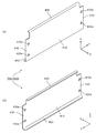
- FIG. 4 is a perspective view showing the configuration of the side member according to the embodiment.
- FIG. 5 is a perspective view and a front view showing the configuration of the spacer according to the embodiment.
- FIG. 6 is a front view showing the positional relationship between the power storage element, the spacer, and the side member according to the embodiment.
- the power storage device intersects a power storage element having a container, a spacer having a spacer main body portion arranged on one side of the first direction of the power storage element, and the first direction of the power storage element.
- a side member having a side main body portion arranged on one side of the second direction, and the power storage element is one side of the third direction intersecting the first direction and the second direction from the container.
- the side member has a first side projecting portion that protrudes from the side main body portion to the other side in the second direction toward the electrode terminal, and the spacer has the above-mentioned spacer.
- a first spacer protrusion that is arranged between the electrode terminal and the first side protrusion and projects from the spacer body to one side in the third direction rather than at least one of the electrode terminal and the first side protrusion. Has a part.
- the side member has a first side protrusion that protrudes toward the electrode terminal of the power storage element, and the spacer is formed between the electrode terminal and the first side protrusion. It has a first spacer protrusion that protrudes from at least one of the above.
- the first side protruding portion of the side member is arranged so as to project toward the electrode terminal of the power storage element, the electrode terminal and the first side protruding portion may be short-circuited. Therefore, in the spacer, the first spacer protruding portion that protrudes from at least one of them is arranged between the electrode terminal and the first side protruding portion. As a result, the electrical insulation between the electrode terminal and the first side protrusion can be improved, so that the possibility of a short circuit between the power storage element and the side member can be reduced.
- the side member is arranged at a position where the container is sandwiched between the first side projecting portion, and further has a second side projecting portion projecting from the side main body portion to the other side in the second direction, and the spacer. May further have a second spacer projecting portion that is arranged on the other side of the second side projecting portion in the second direction and projects from the spacer main body portion to the other side in the third direction.
- the side member has a second side protrusion that protrudes to the other side in the second direction at a position where the container of the power storage element is sandwiched between the first side protrusion and the spacer.
- the second spacer protrusion is provided on the other side of the second side protrusion in the second direction.
- the second spacer protrusion is arranged on the other side of the second side protrusion in the second direction.
- the electrical insulation between the container and the second side protrusion can be improved, so that the possibility of a short circuit between the power storage element and the side member can be reduced.
- the container may be arranged on the other side of the first side projecting portion in the third direction and may have a container projecting portion projecting to one side in the second direction.
- the container of the power storage element has a container protrusion that protrudes to one side in the second direction on the other side of the third direction of the first side protrusion of the side member. Widens in the second direction. Therefore, the contact area between the power storage element and the spacer is increased, and the movement of the power storage element in the third direction is suppressed. As a result, the possibility of a short circuit between the power storage element and the side member can be reduced.
- the spacer may further have a first contact portion that is arranged between the first side protrusion and the container protrusion and that the container protrusion contacts in the third direction.
- the spacer has a first contact portion in which the container protrusion contacts in the third direction between the first side protrusion of the side member and the container protrusion of the container of the power storage element. ..
- the first contact portion of the spacer between the first side protrusion and the container protrusion, it is possible to improve the electrical insulation between the first side protrusion and the container protrusion. Therefore, the possibility of a short circuit between the power storage element and the side member can be reduced.
- the spacer may be further provided with a second contact portion that is arranged between the side main body portion and the container protrusion portion and that the container protrusion portion contacts in the second direction.
- the spacer has a second contact portion in which the container protrusion contacts in the second direction between the side main body portion of the side member and the container protrusion portion of the container of the power storage element.
- the arrangement direction of the pair of electrode terminals in one storage element the opposite direction of the pair of short sides in the container of one storage element, the arrangement direction of the pair of side members, or the storage element and the side.
- the alignment direction with the members is defined as the X-axis direction.
- the thickness direction of the power storage element, spacer, or end member is defined as the Y-axis direction.
- the alignment direction of the container body and the lid of the electricity storage element, the arrangement direction of the energy storage element, the bus bar holding member and the bus bar, or the vertical direction is defined as the Z-axis direction.
- These X-axis directions, Y-axis directions, and Z-axis directions intersect each other (orthogonally in the present embodiment).
- the Z-axis direction may not be the vertical direction, but for convenience of explanation, the Z-axis direction will be described below as the vertical direction.
- the X-axis plus direction indicates the arrow direction of the X-axis in each figure
- the X-axis minus direction indicates the direction opposite to the X-axis plus direction.
- the Y-axis direction and the Z-axis direction may be referred to as a first direction
- the X-axis direction may be referred to as a second direction
- the Z-axis direction may be referred to as a third direction.
- the power storage device 10 shown in FIG. 1 will be described as a case where the power storage device 10 is viewed in the positive direction of the Y-axis.
- FIG. 1 is a perspective view showing the appearance of the power storage device 10 according to the present embodiment.
- FIG. 2 is an exploded perspective view showing each component when the power storage device 10 according to the present embodiment is disassembled.
- the power storage device 10 is a device capable of charging electricity from the outside and discharging electricity to the outside, and has a substantially rectangular parallelepiped shape in the present embodiment.
- the power storage device 10 is a battery module (assembled battery) used for power storage or power supply.
- the power storage device 10 is a battery for driving a moving body such as an automobile, a motorcycle, a watercraft, a snowmobile, an agricultural machine, a construction machine, or a railroad vehicle for an electric railway, or for starting an engine. Used as.
- Examples of the above-mentioned vehicle include an electric vehicle (EV), a hybrid electric vehicle (HEV), a plug-in hybrid electric vehicle (PHEV), and a gasoline vehicle.
- Examples of the above-mentioned railway vehicle for electric railways include trains, monorails, and linear motor cars.
- the power storage device 10 can also be used as a stationary battery or the like used for home use, a generator, or the like.
- the power storage device 10 includes a plurality of power storage elements 100, a plurality of spacers 200, a pair of end members 300, a pair of side members 400 (400a, 400b), and a bus bar holding member. It includes 500, a plurality of bus bars 600, and a substrate 700.
- the power storage element 100 is a secondary battery (cell battery) capable of charging electricity and discharging electricity, and more specifically, a non-aqueous electrolyte secondary battery such as a lithium ion secondary battery.
- the power storage element 100 has a flat rectangular parallelepiped shape (square shape), and is arranged adjacent to the spacer 200. That is, each of the plurality of power storage elements 100 is alternately arranged with each of the plurality of spacers 200, and is arranged in the Y-axis direction (first direction). In the present embodiment, 13 spacers 200 are arranged at positions sandwiching each of the 12 power storage elements 100.
- the number of power storage elements 100 is not limited to 12, and may be a plurality of power storage elements other than 12, or may be one.
- the shape of the power storage element 100 is not particularly limited, and may be any shape such as a polygonal pillar shape, a cylindrical shape, an elliptical pillar shape, an oval pillar shape, etc. other than the rectangular parallelepiped shape. You can also do it.
- the power storage element 100 is not limited to the non-aqueous electrolyte secondary battery, and may be a secondary battery other than the non-aqueous electrolyte secondary battery, or may be a capacitor.
- the power storage element 100 may not be a secondary battery but a primary battery that can use the stored electricity without being charged by the user. Further, the power storage element 100 may be a battery using a solid electrolyte. A detailed description of the configuration of the power storage element 100 will be described later.
- the spacer 200 is arranged in the Y-axis plus direction or the Y-axis minus direction (one side or the other side of the first direction) of the power storage element 100, and is a rectangular shape and a plate that electrically insulates the power storage element 100 from another member. It is a shaped spacer. Specifically, the spacer 200 is arranged between two adjacent power storage elements 100 and between the power storage element 100 at the end and the end member 300, and is arranged between the two power storage elements 100 and at the end. Insulate between the power storage element 100 and the end member 300. In the present embodiment, 13 spacers 200 are arranged corresponding to 12 power storage elements 100, but when the number of power storage elements 100 is other than 12, the number of spacers 200 is also the power storage element 100. It is changed according to the number of.
- the spacer 200 is formed by the spacer side wall portion 220 (see FIG. 5) described later, thereby forming a Y of the short side surface of the power storage element 100 (short side surface portion 122 described later). Approximately half of the minus axis side or the plus direction side of the Y axis is also formed to cover. With such a configuration, the two spacers 200 sandwiching the power storage element 100 cover the short side surface of the power storage element 100, so that the electrical insulation between the power storage element 100 and the side member 400 can be ensured. .. In particular, in the present embodiment, the spacer side wall portions 220 of the two spacers 200 that sandwich the power storage element 100 overlap each other, so that the two spacers 200 cover the entire short side surface of the power storage element 100. ..
- the spacer 200 includes polycarbonate (PC), polypropylene (PP), polyethylene (PE), polyphenylene sulfide resin (PPS), polyphenylene ether (PPE (including modified PPE)), polyethylene terephthalate (PET), and polyetheretherketone (PET). Insulation of PEEK), tetrafluoroethylene / perfluoroalkyl vinyl ether (PFA), polytetrafluoroethylene (PTFE), polybutylene terephthalate (PBT), polyether sulfone (PES), ABS resin, and composite materials thereof. It is made of the resin material of.
- the spacer 200 may be made of a material other than resin as long as it has electrical insulating properties, and is made of ceramic, a dammer material formed by accumulating and bonding mica pieces, or the like. May be good. Not all of the plurality of spacers 200 need to be made of the same material. A more detailed description of the configuration of the spacer 200 will be described later.
- the end member 300 and the side member 400 are members that press the power storage element 100 from the outside in the arrangement direction (Y-axis direction, first direction) of the plurality of power storage elements 100. That is, the end member 300 and the side member 400 sandwich the plurality of power storage elements 100 from both sides in the arrangement direction, thereby pressing each storage element 100 included in the plurality of storage elements 100 from both sides in the arrangement direction.
- the end members 300 are arranged on both sides of the plurality of power storage elements 100 in the Y-axis direction, and the plurality of power storage elements 100 are sandwiched from both sides in the arrangement direction (Y-axis direction) of the plurality of power storage elements 100. It is a flat block-shaped end plate (holding member) to be held.
- the end member 300 is made of a metal (conductive) material such as aluminum, aluminum alloy, stainless steel, iron, and galvanized steel sheet from the viewpoint of ensuring strength.
- the material of the end member 300 is not particularly limited, and may be formed of, for example, a high-strength insulating material or may be subjected to an insulating treatment.
- the end member 300 may be a plate-shaped end plate or the like instead of a block-shaped end plate.
- the side members 400 are arranged on both sides of the plurality of power storage elements 100 in the X-axis direction (both sides in the second direction intersecting the first direction), and both ends are attached to the end member 300 to restrain the plurality of power storage elements 100. It is a long and flat side plate (restraint member, restraint bar). That is, the side member 400 is arranged so as to extend in the Y-axis direction so as to straddle the plurality of power storage elements 100 and the plurality of spacers 200, and these are arranged with respect to the plurality of power storage elements 100 and the plurality of spacers 200. A binding force is applied in the direction (Y-axis direction).
- a pair of side members 400 are arranged on both sides of the plurality of power storage elements 100 and the plurality of spacers 200 in the X-axis direction.
- Each of the pair of side members 400 is attached to the X-axis direction ends of the pair of end members 300 at both ends in the Y-axis direction.
- the pair of side members 400 sandwich and restrain the plurality of power storage elements 100 and the plurality of spacers 200 from both sides in the X-axis direction and both sides in the Y-axis direction.
- the side member 400 on the minus direction side of the X axis is also referred to as a side member 400a
- the side member 400 on the plus direction side of the X axis is also referred to as a side member 400b.
- the side member 400 is joined to the end member 300 by a plurality of joining members 460 arranged in the Z-axis direction.
- the joining member 460 is a bolt that penetrates the side member 400 and is fastened to the end member 300.
- the side member 400 is made of a metal (conductive) material such as aluminum, aluminum alloy, stainless steel, iron, and galvanized steel sheet from the viewpoint of ensuring strength.
- the side member 400 may be a block-shaped or rod-shaped member or the like instead of a plate-shaped side plate. A detailed description of the configuration of the side member 400 will be described later.
- the bus bar holding member 500 holds the bus bar 600, the substrate 700, and the like, and is a plate-shaped member (bus bar) capable of electrically insulating the bus bar 600 and the like from other members and restricting the position of the bus bar 600 and the like. Plate, bus bar frame).
- the bus bar holding member 500 is made of an insulating resin material or the like similar to the spacer 200 such as PC, PP, PE.
- the bus bar 600 is a conductive plate-shaped member that is arranged on a plurality of power storage elements 100 and electrically connects the electrode terminals (electrode terminals 140 described later) of the plurality of power storage elements 100.
- a plurality of bus bars 600 are used to connect the positive electrode terminals and the negative electrode terminals of the adjacent storage element 100s in order to connect the plurality of storage elements 100 in series.
- An external terminal 610 (positive electrode external terminal, negative electrode external terminal), which is a terminal of the power storage device 10, is connected to the bus bar 600 arranged at the end.
- the bus bar 600 and the electrode terminals are connected by laser welding.
- the bus bar 600 also includes a wiring connection portion for detecting the voltage of the power storage element 100 and the like, and the connection portion is bent in the Z-axis plus direction.
- the bus bar 600 is made of a conductive member made of metal such as copper, copper alloy, aluminum, or aluminum alloy.
- the connection form between the power storage elements 100 is not particularly limited, and any power storage element 100 may be connected in parallel.
- the connection method between the bus bar 600 and the electrode terminal may be welding other than laser welding, or may be screw fastening or the like according to the shape of the electrode terminal.
- the board 700 is a circuit board mounted on the bus bar holding member 500, and electronic components, fuses, relays, shunt resistors, connectors, etc. for monitoring the charging state or discharging state of the power storage element 100 are arranged.
- Wiring 710 is connected to the board 700 via a connector. In the present embodiment, the wiring 710 is focused and connected to the substrate 700 at the end of the power storage device 10 in the positive direction of the Y-axis.
- the wiring 710 includes a wiring for measuring the voltage of the power storage element 100, a wiring for measuring the temperature, and the like, and one end of the wiring is connected to the connection portion of the bus bar 600.
- FIG. 3 is a perspective view showing the configuration of the power storage element 100 according to the present embodiment.
- the power storage element 100 includes a container 110, a pair of electrode terminals 140 (positive electrode terminal and negative electrode terminal), and a pair of gaskets 150.
- An electrode body, a current collector (positive electrode current collector and a negative electrode current collector), an electrolytic solution (non-aqueous electrolyte), and the like are housed inside the container 110, but these are not shown.
- the type of the electrolytic solution is not particularly limited as long as it does not impair the performance of the power storage element 100, and various types can be selected.
- Spacers may be arranged on the side of the current collector, or an insulating sheet covering the outer surface of the container 110 may be arranged.
- the container 110 is a rectangular parallelepiped (square) container having a container body 120 having an opening formed and a lid body 130 closing the opening of the container body 120.
- the container body 120 is a rectangular tubular member having a bottom that constitutes the main body of the container 110, has a pair of long side surface portions 121 on both side surfaces in the Y-axis direction, and a pair on both side surfaces in the X-axis direction. It has a short side surface portion 122 and a bottom surface portion 123 on the negative direction side of the Z axis.
- the short side surface portion 122 is a rectangular flat surface adjacent to the pair of long side surface portions 121 and the bottom surface portion 123 and having a smaller area than the long side surface portion 121.
- the bottom surface portion 123 is a rectangular flat surface adjacent to a pair of long side surface portions 121 and a pair of short side surface portions 122.
- the long side surface portion 121 is a rectangular flat surface adjacent to the pair of short side surface portions 122 and the bottom surface portion 123 and having a larger area than the short side surface portion 122.
- the lid 130 is a rectangular plate-shaped member that constitutes the lid (upper surface) of the container 110, and is arranged on the Z-axis plus direction side of the container body 120.
- the lid 130 is also provided with a gas discharge valve 131 that releases the pressure inside the container 110 when the pressure rises, a liquid injection section 132 for injecting the electrolytic solution into the inside of the container 110, and the like. ing.
- the container 110 has a structure in which the inside of the container 110 is sealed by accommodating the electrode body and the like inside the container body 120 and then joining the container body 120 and the lid 130 by welding or the like. ing.
- the material of the container 110 is not particularly limited, but is preferably a weldable (bondable) metal such as stainless steel, aluminum, aluminum alloy, iron, or plated steel plate.
- the container 110 has a container protrusion 110a that protrudes outward.
- the container projecting portion 110a is a projecting portion formed over the entire circumference of the lid body 130 and the end portion of the container body 120 on the lid body 130 side (Z-axis plus direction side). Since the lid 130 is the upper surface portion of the container 110, the container protrusion 110a includes a part of the upper surface portion of the container 110. That is, the container protrusion 110a has a pair of long side surface protrusions 111 at the ends of the pair of long side surface portions 121 on the Z-axis plus direction side, and the end portions of the pair of short side surface portions 122 on the Z-axis plus direction side. Has a pair of short side protrusions 112.
- the pair of long side surface protrusions 111 have a shape that extends in the X-axis direction and gradually expands in the Y-axis direction (inclined with respect to the Z-axis direction) toward the Z-axis plus direction.
- the pair of short side surface portions 122 have a shape that extends in the Y-axis direction and gradually expands in the X-axis direction (inclined with respect to the Z-axis direction) toward the Z-axis plus direction.
- the container projecting portion 110a is formed by the pair of long side surface projecting portions 111, the pair of short side surface projecting portions 112, and the outer peripheral portion of the lid 130, and gradually outwards toward the Z-axis plus direction. It is a tapered part that protrudes toward the surface.
- Such a container protrusion 110a is formed in the container 110 for the following reasons.
- the lid 130 of the container body 120 is used.
- a container protrusion 110a may be formed at the side end.
- a container protrusion 110a may be formed at the end of the container body 120 on the lid 130 side so that the opening of the container body 120 can be widened so that the contents such as the electrode body can be easily inserted into the container body 120.
- a container protrusion 110a for engaging with or fitting with the other member may be formed.
- the container protruding portion 110a at the end of the container body 120 which is difficult to swell (in the present embodiment, the end on the lid 130 side). preferable.
- the electrode terminal 140 is a terminal (positive electrode terminal and negative electrode terminal) of the power storage element 100 arranged on the lid 130 of the container 110, and is electrically connected to the positive electrode plate and the negative electrode plate of the electrode body via a current collector.
- the electrode terminal 140 is made of metal for leading the electricity stored in the electrode body to the external space of the power storage element 100 and introducing electricity into the internal space of the power storage element 100 in order to store electricity in the electrode body. It is a member.
- the electrode terminal 140 is arranged so as to project from the lid 130 of the container 110 in the Z-axis plus direction (one side of the third direction intersecting the first direction and the second direction).
- the electrode terminal 140 has a flat plate shape because it is welded to the bus bar 600, it may be provided with a bolt terminal so that it can be screwed.
- the electrode terminal 140 is made of aluminum, an aluminum alloy, copper, a copper alloy, or the like.
- the gasket 150 is arranged between the electrode terminal 140 and the lid 130, and between the lid 130 and the current collector, and is arranged between the electrode terminal 140 and the lid 130, and between the lid 130 and the current collector. It is a member for ensuring electrical insulation and airtightness with the body.
- the gasket 150 is made of an insulating material such as PP, PE, PPS, PET, PEEK, PFA, PTFE, PBT, PES, or ABS resin.
- the electrode body is a power storage element (power generation element) formed by laminating a positive electrode plate, a negative electrode plate, and a separator.
- the positive electrode plate of the electrode body is formed by forming a positive electrode active material layer on a positive electrode base material layer which is a long strip-shaped current collecting foil made of a metal such as aluminum or an aluminum alloy.
- the negative electrode plate is a negative electrode active material layer formed on a negative electrode base material layer which is a long strip-shaped current collecting foil made of a metal such as copper or a copper alloy.
- known materials can be appropriately used as long as they can store and release lithium ions.
- the current collector is a member (positive electrode current collector and negative electrode current collector) having conductivity and rigidity electrically connected to the electrode terminal 140 and the electrode body.
- the positive electrode current collector is formed of aluminum or an aluminum alloy or the like like the positive electrode base material layer of the positive electrode plate
- the negative electrode current collector is formed of copper or a copper alloy or the like like the negative electrode base material layer of the negative electrode plate.
- the X-axis plus direction when looking at the X-axis plus direction side of the power storage device 10, the X-axis plus direction is interpreted as one side of the second direction, and when looking at the X-axis minus direction side of the power storage device 10, X.
- the minus direction of the axis is interpreted as one side of the second direction.
- FIG. 4 is a perspective view showing the configuration of the side member 400 according to the present embodiment.
- FIG. 4A is a perspective view showing the configuration of the side member 400b on the X-axis plus direction side in FIG. 2.
- FIG. 4B is a perspective view showing a configuration when the side member 400b of FIG. 4A is viewed from the opposite side in the X-axis direction.
- the side member 400b on the plus direction side of the X axis and the side member 400a on the minus direction side of the X axis have the same shape, and have the same configuration when rotated by 180 ° around the Z axis.
- the side member 400 includes a side main body portion 410, side connecting portions 420 and 430, a first side protruding portion 440, and a second side protruding portion 450.
- the side member 400b on the plus direction side of the X axis will be described, and the side member 400a on the minus direction side of the X axis will be described in detail because the direction in the X axis direction is reversed. The explanation is omitted.
- the side main body 410 shown in FIG. 4 is a rectangular and flat plate-shaped portion constituting the main body of the side member 400b, and is arranged parallel to the YZ plane and extended in the Y-axis direction. As shown in FIG. 6 described later, the side main body 410 of the side member 400b is arranged in the X-axis plus direction (one side in the second direction) of the power storage element 100. Specifically, the side main body 410 is arranged in the X-axis plus direction of the power storage element 100 and the spacer 200. That is, the side main body 410 of the side member 400b is arranged on the X-axis plus direction side of the power storage element 100 and the spacer 200.
- the side connection portion 420 is an end portion of the side member 400b on the Y-axis minus direction side, and is arranged so as to extend from the end edge of the side main body portion 410 on the Y-axis minus direction side to the Y-axis minus direction side. That is, the side connecting portion 420 is a rectangular and flat plate-shaped portion that is continuous from the side main body portion 410 and extends in the minus direction side of the Y axis, is parallel to the YZ plane, and extends in the Z axis direction.
- the side connection portion 420 is formed with two circular through holes 420a arranged in the Z-axis direction that penetrate the side connection portion 420 in the X-axis direction.
- the side connecting portion 420 is connected (fixed) to the end member 300 by inserting the joining member 460 into the through hole 420a and fastening the joining member 460 to the end portion of the end member 300.
- the side connection portion 430 is an end portion of the side member 400b on the Y-axis plus direction side, and is arranged so as to extend from the end edge of the side main body portion 410 on the Y-axis plus direction side to the Y-axis plus direction side. That is, the side connecting portion 430 is a rectangular and flat plate-shaped portion that is continuous from the side main body portion 410 and extends in the positive direction of the Y-axis, is parallel to the YZ plane, and extends in the Z-axis direction.
- the side connection portion 430 is formed with two circular through holes 430a arranged in the Z-axis direction that penetrate the side connection portion 430 in the X-axis direction.
- the side connecting portion 430 is connected (fixed) to the end member 300 by inserting the joining member 460 into the through hole 430a and fastening the joining member 460 to the end portion of the end member 300.
- the first side protruding portion 440 is an end portion of the side member 400b on the Z-axis plus direction side, and is arranged so as to protrude in the X-axis direction from the end portion of the side main body portion 410 on the Z-axis plus direction side.
- the first side protruding portion 440 is a rectangular and flat plate-shaped portion arranged parallel to the XY plane and extended in the Y-axis direction.
- the first side protrusion 440 is X-axis negative from the side main body 410 toward the electrode terminal 140 of the power storage element 100. It is arranged so as to project in the direction (the other side of the second direction).
- the second side projecting portion 450 is an end portion of the side member 400b on the Z-axis minus direction side, and is arranged so as to project in the X-axis direction from the end portion of the side main body portion 410 on the Z-axis minus direction side.
- the second side protruding portion 450 is a rectangular and flat plate-shaped portion arranged parallel to the XY plane and extended in the Y-axis direction.
- the second side protrusion 450 is arranged at a position where the container 110 of the power storage element 100 is sandwiched between the first side protrusion 440 and the first side protrusion 440. It is arranged so as to project from the side main body 410 in the minus direction of the X axis (the other side in the second direction).
- FIG. 5 is a perspective view and a front view showing the configuration of the spacer 200 according to the present embodiment.
- FIG. 5A is a perspective view showing the configuration of the spacer 200 shown in FIG.
- FIG. 5B is an enlarged front view showing the configuration of the spacer 200 on the X-axis minus direction side and the Z-axis plus direction side when viewed from the Y-axis minus direction side.
- (C) is a perspective view of the portion (b) of FIG. 5 as viewed from the opposite side (Y-axis plus direction side) of FIG. 5 (a).
- FIG. 5A is a perspective view showing the configuration of the spacer 200 shown in FIG.
- FIG. 5B is an enlarged front view showing the configuration of the spacer 200 on the X-axis minus direction side and the Z-axis plus direction side when viewed from the Y-axis minus direction side.
- (C) is a perspective view of the portion (b) of FIG. 5 as viewed from the opposite side (
- 5D is an enlarged front view showing the configuration of the spacer 200 on the X-axis minus direction side and the Z-axis minus direction side when viewed from the Y-axis minus direction side.
- E is a perspective view of the portion (d) of FIG. 5 as viewed from the opposite side (Y-axis plus direction side) of FIG. 5 (a).
- FIG. 6 is a front view showing the positional relationship between the power storage element 100, the spacer 200, and the side member 400 according to the present embodiment.
- FIG. 6A is a front view showing a configuration in which the power storage element 100, the spacer 200, and the side member 400 are assembled, as viewed from the Y-axis minus direction side.
- FIG. 6B is an enlarged front view showing the configuration of the configuration of FIG. 6A when the end portions on the X-axis minus direction side and the Z-axis plus direction side are viewed from the Y-axis minus direction side. It is a figure.
- the side member 400 is a cross-sectional view.
- the spacer 200 has a spacer main body portion 210 and a spacer side wall portion 220.
- the spacer main body 210 is a rectangular and flat plate-shaped portion constituting the main body of the spacer 200, and is arranged parallel to the XZ plane. As described above, the spacer main body 210 is arranged on both sides (both sides in the first direction) of the power storage element 100 in the Y-axis direction.
- FIG. 6 illustrates a state in which the spacer main body 210 is arranged on the Y-axis plus direction side of the power storage element 100 (the spacer main body 210 is hidden behind the power storage element 100 and cannot be seen).
- the spacer side wall portion 220 is a wall portion that is arranged so as to extend in the Z-axis direction at the end portion of the spacer 200 in the X-axis direction and is arranged so as to cover the end portion of the power storage element 100 in the X-axis direction.
- the spacer main body portion 210 is defined as the spacer side wall portion 220 including both the Y-axis minus direction side and the Y-axis plus direction side.
- Two spacer side wall portions 220 are arranged at both ends of the spacer 200 in the X-axis direction to cover both ends of the power storage element 100 in the X-axis direction.
- the two spacer side wall portions 220 include a pair of short side surface portions 122 of the container 110 of the power storage element 100, both ends of the lid 130 in the X-axis direction, and both ends of the bottom surface portion 123 in the X-axis direction. It is arranged so as to cover approximately half of the portion in the Y-axis direction.
- the spacer side wall portions 220 of the two spacers 200 that sandwich the container 110 of the power storage element 100 overlap each other, so that the two spacer side wall portions 220 cover the entire surface of the short side surface portion 122 of the power storage element 100. It is configured to be covered without gaps.
- a stepped portion 220a having a concave outer surface and extending in the Z-axis direction is formed at a portion of the spacer side wall portion 220 on the negative direction side of the Y-axis.
- a stepped portion 220b having a recessed inner surface and extending in the Z-axis direction is formed at a portion of the spacer side wall portion 220 on the Y-axis plus direction side.
- Each of the spacer side wall portions 220 of the plurality of spacers 200 has a first contact portion 221 and a second contact portion 222, a first spacer protrusion 223, a third contact portion 224, and a second spacer protrusion. It has 225 and.
- Each of the first contact portion 221 and the second contact portion 222, the first spacer protrusion 223, the third contact portion 224, and the second spacer protrusion 225 is a portion of the spacer side wall portion 220 on the negative direction side of the Y axis. And a part of the part on the positive side of the Y-axis are included.
- the spacer side wall 220 on the X-axis plus direction side and the spacer side wall 220 on the X-axis minus direction side have the same configuration. Therefore, for convenience of explanation, the configuration of the spacer side wall portion 220 on the X-axis minus direction side will be described in detail below, and the description of the configuration of the spacer side wall portion 220 on the X-axis plus direction side will be omitted. Further, the side member 400 related to the following description of the spacer side wall portion 220 is a side member 400a on the minus direction side of the X axis.
- the first contact portion 221 is a rectangular and flat plate-shaped portion parallel to the XY plane, which is arranged at the end of the spacer side wall portion 220 on the Z-axis plus direction side.
- the end of the first contact portion 221 on the minus direction side of the X axis is connected to the end of the second contact portion 222 on the plus direction of the Z axis, and the end on the plus direction of the X axis is the protrusion of the first spacer. It is connected to and arranged at the end of the 223 on the negative side of the Z axis.
- the first contact portion 221 is arranged between the first side protruding portion 440 of the side member 400a and the container protruding portion 110a of the container 110 in the Z-axis direction. That is, the container protrusion 110a is arranged in the Z-axis minus direction (the other side in the third direction) of the first side protrusion 440 and the first contact portion 221, and the first contact portion 221 projects on the first side.
- the portion 440 is arranged in the negative direction of the Z axis. As a result, the container protrusion 110a comes into contact with the first contact portion 221 in the Z-axis plus direction (one side in the third direction).
- the inner surface of the first contact portion 221 abuts on the container protruding portion 110a.
- the first contact portion 221 has a surface facing the container protrusion 110a (inner surface, a surface on the Z-axis minus direction side) so that the Y-axis minus direction is directed toward the Z-axis plus direction (container protrusion).
- the inclined surface is slightly inclined in the direction away from 110a), and this inclined surface comes into contact with the container protrusion 110a.
- the first contact portion 221 is arranged in a state of being separated from the first side protruding portion 440.
- the second contact portion 222 is a rectangular and flat plate-shaped portion parallel to the YZ plane, which is arranged at the end of the spacer side wall portion 220 on the Z-axis plus direction side.
- the second contact portion 222 is arranged so that the end portion on the Z-axis positive direction side is connected to the end portion on the X-axis negative direction side of the first contact portion 221.
- the second contact portion 222 is arranged between the side main body portion 410 and the container protruding portion 110a of the side member 400a in the X-axis direction. That is, the container projecting portion 110a protrudes in the minus direction of the X axis (one side in the second direction), and is arranged in the plus direction of the X axis of the second contact portion 222 and the side main body portion 410, and the second contact portion The 222 is arranged in the X-axis plus direction of the side main body 410. As a result, the container protruding portion 110a comes into contact with the second contact portion 222 in the minus direction of the X axis (one side in the second direction). That is, in the X-axis direction (second direction), the inner surface of the second contact portion 222 abuts on the container protruding portion 110a.
- the container protrusion 110a is inclined with respect to the second contact portion 222 on the surface facing the second contact portion 222 (the surface of the short side protrusion 112 on the X-axis minus direction side). It has an inclined surface, and this inclined surface comes into contact with the second contact portion 222. Specifically, the surface of the container protrusion 110a on the minus direction side of the X axis is inclined in the plus direction of the X axis (direction away from the second contact portion 222) toward the minus direction of the Z axis.
- the surface of the second contact portion 222 facing the container protrusion 110a (the surface on the X-axis plus direction side) is slightly in the X-axis minus direction (direction away from the container protrusion 110a) as the Y-axis minus direction. It is an inclined surface.
- a recess 222a recessed in the X-axis minus direction is formed with the inclined surface as the bottom surface.
- the container protrusion 110a is housed in the recess 222a.
- the second contact portion 222 and the container projecting portion 110a each have inclined surfaces inclined in different directions, and the inclined surfaces come into contact with each other.
- the third contact portion 224 is a rectangular and flat plate-shaped portion parallel to the XY plane, which is arranged at the end portion of the spacer side wall portion 220 on the negative direction side of the Z axis.
- the third contact portion 224 is arranged so that the end portion on the X-axis plus direction side is connected to the end portion on the Z-axis plus direction side of the second spacer protrusion 225.
- the third contact portion 224 is arranged between the second side protruding portion 450 of the side member 400a and the bottom surface portion 123 of the container 110. As a result, the bottom surface portion 123 comes into contact with the third contact portion 224 in the negative direction of the Z axis.
- the surface facing the bottom surface portion 123 (the surface on the Z-axis plus direction side) is oriented in the Y-axis minus direction in the Z-axis minus direction (direction away from the bottom surface portion 123). ) Is a slightly inclined inclined surface, and this inclined surface comes into contact with the bottom surface portion 123.
- the third contact portion 224 is arranged at a position where the container 110 is sandwiched between the third contact portion 221 and the first contact portion 221. In this way, the spacer 200 sandwiches the container 110 in the Z-axis direction between the first contact portion 221 and the third contact portion 224.
- the side member 400a sandwiches the first contact portion 221 and the third contact portion 224 of the spacer 200 in the Z-axis direction between the first side protrusion 440 and the second side protrusion 450. With this configuration, the movement of the power storage element 100 in the Z-axis direction is restricted.
- the container protrusion 110a does not have to be in contact with the first contact portion 221 at all times, and the container protrusion 110a usually has a gap formed between it and the first contact portion 221 and vibrates from the outside. Alternatively, it may be configured to come into contact with the first contact portion 221 when an impact is applied. Similarly, the container protrusion 110a may not always be in contact with the second contact portion 222, and the bottom surface portion 123 may not always be in contact with the third contact portion 224.
- the first spacer protruding portion 223 is a rectangular and flat plate-shaped portion parallel to the YZ plane that protrudes in the Z-axis plus direction from the end of the first contact portion 221 on the X-axis plus direction side. Since the first spacer protruding portion 223 is also connected to the spacer main body 210, it can be said that the first spacer protruding portion 223 protrudes from the spacer main body 210 in the positive direction on the Z axis.
- the first spacer protrusion 223 is arranged between the electrode terminal 140 of the power storage element 100 and the first side protrusion 440 of the side member 400a in the X-axis direction. That is, the first spacer protrusion 223 is arranged so as to partition between the electrode terminal 140 and the first side protrusion 440 in a state of being separated from the electrode terminal 140 and the first side protrusion 440. Specifically, the first spacer protrusion 223 is arranged so as to protrude from the spacer main body 210 in the Z-axis plus direction from both the electrode terminal 140 and the first side protrusion 440.
- the first spacer protrusion 223 protrudes from the spacer main body 210 (and the end of the first contact portion 221 on the X-axis plus direction side) in the Z-axis plus direction, and the electrode terminal 140 and the first side protrude. It is extended and arranged to a position on the Z-axis plus direction side of both of the portions 440.
- the first spacer protrusion 223 may be arranged so as to protrude from the spacer main body 210 in the Z-axis plus direction (one side in the third direction) from at least one of the electrode terminal 140 and the first side protrusion 440. .. That is, the first spacer protruding portion 223 may be arranged so as to project in the Z-axis positive direction from the members of the electrode terminal 140 and the first side protruding portion 440 that are arranged in the Z-axis negative direction. In the present embodiment, the outer surface of the electrode terminal 140 in the Z-axis direction is arranged in the Z-axis minus direction with respect to the first side protrusion 440.
- the highest point of the first spacer protruding portion 223 in the Z-axis direction may be arranged so as to project at least in the Z-axis plus direction from the outer surface of the electrode terminal 140.
- the height H1 of the outer surface of the electrode terminal 140 is lower than the height H2 of the surface of the first side protrusion 440 in the Z-axis plus direction.
- the height H3 of the surface of the first spacer protrusion 223 in the plus direction of the Z axis is higher than the height H1 of the outer surface of the electrode terminal 140.
- the highest point of the first spacer protrusion 223 in the Z-axis direction is at least from the first side protrusion 440. May be arranged so as to project in the positive direction of the Z axis, and may be arranged in the negative direction of the Z axis with respect to the outer surface of the electrode terminal 140. Specifically, if the height H1 of the electrode terminal 140 is higher than the height H2 of the first side protrusion 440, the height H3 of the first spacer protrusion 223 is at least the first side protrusion 440. It may be higher than the height H2 of the electrode terminal 140, and may be lower than the height H1 of the electrode terminal 140.
- the first spacer protrusion 223 is arranged so as to protrude from both the electrode terminal 140 and the first side protrusion 440, that is, the first side protrusion 440 in the Z-axis plus direction.
- the height H3 of the first spacer protrusion 223 is preferably higher than the height H1 of the electrode terminal 140 and the height H2 of the first side protrusion 440.
- the second spacer protruding portion 225 is a rectangular and flat plate-shaped portion parallel to the YZ plane that protrudes in the Z-axis minus direction from the end of the third contact portion 224 on the X-axis plus direction side. Since the second spacer protruding portion 225 is also connected to the spacer main body 210, it can be said that the second spacer protruding portion 225 protrudes from the spacer main body 210 in the negative direction of the Z axis (the other side in the third direction).
- the second spacer protrusion 225 is arranged in the X-axis plus direction (the other side in the second direction) of the second side protrusion 450 of the side member 400a. That is, the second spacer protrusion 225 protrudes in the negative direction of the Z axis so as to partition the second side protrusion 450 from the bottom surface 123 of the container 110 in a state of being separated from the second side protrusion 450. Be placed.
- the amount of protrusion of the second spacer protrusion 225 is not particularly limited, but the second spacer protrusion 225 is located at the same position as the surface of the second side protrusion 450 on the negative side in the Z-axis direction, or from the surface. Is also preferably arranged so as to extend to a position on the negative side of the Z axis.
- the side member 400 has a first side protrusion 440 that protrudes toward the electrode terminal 140 of the power storage element 100, and the spacer 200 has a spacer 200.
- a first spacer protrusion 223 that protrudes from at least one of these is provided between the electrode terminal 140 and the first side protrusion 440.
- the first spacer protrusion 223 that protrudes from at least one of these is arranged between the electrode terminal 140 and the first side protrusion 440.
- the electrical insulation between the electrode terminal 140 and the first side protrusion 440 can be improved, so that the possibility of a short circuit between the power storage element 100 and the side member 400 can be reduced.
- the side member 400 projects to the other side in the second direction (X-axis plus direction or X-axis minus direction) at a position where the container 110 of the power storage element 100 is sandwiched between the first side protruding portion 440. It has a two-sided protrusion 450.
- the spacer 200 has a second spacer protrusion 225 on the other side of the second side protrusion 450 in the second direction.
- the second side protrusion 450 of the side member 400 is arranged at a position where the container 110 of the power storage element 100 is sandwiched between the first side protrusion 440 and the container 110 of the power storage element 100, the second side There is a risk that the protrusion 450 will be short-circuited. Therefore, in the spacer 200, the second spacer protrusion 225 is arranged on the other side of the second side protrusion 450 in the second direction. As a result, the insulation distance (space distance and creepage distance) between the container 110 and the second side protrusion 450 can be extended to improve the electrical insulation property, so that the power storage element 100 and the side member 400 are short-circuited. The possibility of occurrence can be reduced.
- the container 110 of the power storage element 100 has neither a positive electrode potential nor a negative electrode potential, but the insulation between the metal container 110 and the other metal member is to be improved. Is important and is effective in extending the insulation distance.
- a configuration for improving the insulating property between the container 110 and another metal member is particularly useful.
- the container 110 of the power storage element 100 has a container protruding portion 110a protruding to one side in the second direction on the other side (Z-axis minus direction) of the first side protruding portion 440 in the third direction.
- the width of the power storage element 100 in the second direction is widened. Therefore, as the area of one surface (the surface facing the spacer 200) of the power storage element 100 in the third direction increases, the contact area between the power storage element 100 and the first contact portion 221 of the spacer 200 increases. , The movement of the power storage element 100 to one side in the third direction (Z-axis plus direction) is suppressed. As a result, the possibility of a short circuit between the power storage element 100 and the side member 400 can be reduced.
- the spacer 200 is arranged on one side of the first direction of the power storage element 100 (Y-axis plus direction or Y-axis minus direction) to suppress the movement of the power storage element 100 in the first direction.
- the side member 400 is arranged on one side in the two directions, and the movement of the power storage element 100 in the second direction is suppressed. As a result, it is possible to prevent the power storage element 100 from moving in the three directions of the first direction, the second direction, and the third direction.
- the spacer 200 has a first contact portion 221 in which the container protrusion 110a abuts in the third direction between the first side protrusion 440 of the side member 400 and the container protrusion 110a of the container 110 of the power storage element 100. are doing. In this way, when the container protruding portion 110a comes into contact with the first contact portion 221, it is possible to further suppress the movement of the power storage element 100 in the third direction, so that a short circuit between the power storage element 100 and the side member 400 occurs. The possibility can be further reduced. By arranging the first contact portion 221 between the first side protruding portion 440 and the container protruding portion 110a, the electrical insulation between the first side protruding portion 440 and the container protruding portion 110a is improved. Therefore, the possibility of a short circuit between the power storage element 100 and the side member 400 can be reduced.
- the spacer 200 has a second contact portion 222 in which the container protrusion 110a abuts in the second direction between the side main body 410 of the side member 400 and the container protrusion 110a of the container 110 of the power storage element 100.
- the second contact portion 222 By arranging the second contact portion 222 between the side main body portion 410 and the container protruding portion 110a in this way, the electrical insulation between the side main body portion 410 and the container protruding portion 110a is improved. Therefore, the possibility of a short circuit between the power storage element 100 and the side member 400 can be reduced.
- the container protrusion 110a comes into contact with the second contact portion 222, it is possible to further suppress the movement of the power storage element 100 in the second direction.
- the container protruding portion 110a of the container 110 has an inclined surface inclined with respect to the second contact portion 222 on the surface of the spacer 200 facing the second contact portion 222.
- the container protrusion 110a is accurately adjusted in order to bring the first contact portion 221 and the container protrusion 110a into contact with each other. It needs to be projected well. Therefore, the surface of the container protrusion 110a facing the second contact portion 222 is inclined with respect to the second contact portion 222.
- the first contact portion 221 can be easily brought into contact with the container protrusion 110a, and the movement of the power storage element 100 in the second direction can be easily regulated. Therefore, the possibility of a short circuit between the power storage element 100 and the side member 400 can be further reduced.
- the side member 400 is a member that restrains the power storage element 100.
- the side member 400 may be a member arranged on the second direction side of the power storage element 100, and does not have to restrain the power storage element 100.
- the side member 400 is made of a conductive material.
- the first side protrusion 440 and the second side protrusion 450 are formed of a conductive material, and the portions other than the first side protrusion 440 and the second side protrusion 450 are insulating. It may be formed or insulated from the material.
- the second side protrusion 450 may also be formed of an insulating material or subjected to an insulating treatment.
- the spacer 200 is made of an insulating material.
- parts other than the first contact portion 221 and the second contact portion 222, the first spacer protrusion 223, the third contact portion 224, and the second spacer protrusion 225 are electrically operated by other means. It may be made of a conductive material as long as the target insulation can be ensured.
- the first contact portion 221 and the second contact portion 222 and the third contact portion 224 may also be made of a conductive material as long as electrical insulation can be ensured by other means.
- the second spacer protrusion 225 may also be formed of a conductive material. That is, at least the first spacer protrusion 223 may be formed of an insulating material.
- the side member 400 has the second side protrusion 450, and the spacer 200 has the second spacer protrusion 225.
- the side member 400 may not have the second side protrusion 450, and the spacer 200 may not have the second spacer protrusion 225.
- the spacer 200 may not have the third contact portion 224.
- the spacer 200 does not have a first contact portion 221 or a second contact portion 222, and another insulating member is arranged at the position of the first contact portion 221 or the second contact portion 222. May be good.
- the container 110 of the power storage element 100 has the container protrusion 110a, but the container 110 does not have to have the container protrusion 110a.
- the first contact portion 221 and the second contact portion 222 of the spacer 200 abut on the upper surface (upper surface portion) and the side surface (short side surface portion) of the container 110.
- all spacers 200 have the above configuration. However, any spacer 200 may not have the above configuration. The same applies to the power storage element 100 and the side member 400.
- the power storage device 10 does not need to include all the components shown in FIG.
- the power storage device 10 may not include the end member 300, the bus bar holding member 500, or the substrate 700.
- the scope of the present invention also includes a form constructed by arbitrarily combining the above-described embodiments and the components included in the above-described modification.
- the present invention can be realized not only as such a power storage device 10, but also as a spacer 200 included in the power storage device 10.
- the present invention can be applied to a power storage device or the like equipped with a power storage element such as a lithium ion secondary battery.
- Power storage device 100 Power storage element 110 Container 110a Container protrusion 111 Long side protrusion 112 Short side protrusion 120 Container body 121 Long side part 122 Short side part 123 Bottom part 130 Lid (upper surface part) 131 Gas discharge valve 132 Lubrication part 140 Electrode terminal 150 Gasket 200 Spacer 210 Spacer body part 220 Spacer side wall part 221 First contact part 222 Second contact part 223 First spacer protrusion 224 Third contact part 225 Second Spacer protrusion 300 End member 400, 400a, 400b Side member 410 Side body part 420, 430 Side connection part 420a, 430a Through hole 440 First side protrusion 450 Second side protrusion 460 Joint member 500 Busbar holding member 600 Busbar 610 External terminal 700 Board 710 Wiring
Landscapes
- Engineering & Computer Science (AREA)
- Power Engineering (AREA)
- Chemical & Material Sciences (AREA)
- Chemical Kinetics & Catalysis (AREA)
- Electrochemistry (AREA)
- General Chemical & Material Sciences (AREA)
- Microelectronics & Electronic Packaging (AREA)
- Materials Engineering (AREA)
- Manufacturing & Machinery (AREA)
- Battery Mounting, Suspending (AREA)
- Electric Double-Layer Capacitors Or The Like (AREA)
Abstract
蓄電装置(10)は、容器(110)を有する蓄電素子(100)と、蓄電素子(100)の第一方向の一方側に配置されるスペーサ本体部(210)を有するスペーサ(200)と、蓄電素子(100)の第一方向と交差する第二方向の一方側に配置されるサイド本体部(410)を有するサイド部材(400)とを備え、蓄電素子(100)は、容器(110)から第一方向及び第二方向と交差する第三方向の一方側に突出する電極端子(140)を有し、サイド部材(400)は、サイド本体部(410)から電極端子(140)に向けて第二方向の他方側に突出する第一サイド突出部(440)を有し、スペーサ(200)は、電極端子(140)及び第一サイド突出部(440)の間に配置され、スペーサ本体部(210)から、電極端子(140)及び第一サイド突出部(440)の少なくとも一方よりも第三方向の一方側に突出する第一スペーサ突出部(223)を有する。
Description
本発明は、蓄電素子と、蓄電素子の側方に配置されるサイド部材とを備える蓄電装置に関する。
従来、蓄電素子と、蓄電素子の側方に配置されるサイド部材とを備える蓄電装置が広く知られている。特許文献1には、複数のバッテリセル(蓄電素子)と、当該複数のバッテリセルの側面に沿って配置された一対のラダーフレーム(サイド部材)と、を備えるバッテリモジュール(蓄電装置)が開示されている。
しかしながら、上記従来のような構成の蓄電装置では、蓄電素子とサイド部材とが短絡してしまうおそれがある。上記特許文献1に開示された蓄電装置(バッテリモジュール)では、蓄電素子(バッテリセル)の容器を上下で挟むように、サイド部材(ラダーフレーム)の上縁及び下縁に上部フランジ及び下部フランジが形成されている。このため、上部フランジが蓄電素子の電極端子の近傍に配置されることとなり、外部から振動または衝撃を受けた際等に、上部フランジと蓄電素子の電極端子とが短絡してしまうおそれがある。この短絡が上部フランジを介して正負の電極端子間で発生すると、蓄電素子の短絡となり不安全状態の要因となり得る。本願発明者は、このように、上記従来のような構成の蓄電装置では、外部から振動または衝撃を受けた際等に、蓄電素子とサイド部材とが短絡してしまうおそれがあることを見出した。
本発明は、蓄電素子とサイド部材との短絡発生の可能性を低減できる蓄電装置を提供することを目的とする。
本発明の一態様に係る蓄電装置は、容器を有する蓄電素子と、前記蓄電素子の第一方向の一方側に配置されるスペーサ本体部を有するスペーサと、前記蓄電素子の前記第一方向と交差する第二方向の一方側に配置されるサイド本体部を有するサイド部材と、を備え、前記蓄電素子は、前記容器から、前記第一方向及び前記第二方向と交差する第三方向の一方側に突出する電極端子を有し、前記サイド部材は、前記サイド本体部から、前記電極端子に向けて前記第二方向の他方側に突出する第一サイド突出部を有し、前記スペーサは、前記電極端子及び前記第一サイド突出部の間に配置され、前記スペーサ本体部から、前記電極端子及び前記第一サイド突出部の少なくとも一方よりも前記第三方向の一方側に突出する第一スペーサ突出部を有する。
本発明は、このような蓄電装置として実現できるだけでなく、当該蓄電装置が備えるスペーサとしても実現できる。
本発明における蓄電装置によれば、蓄電素子とサイド部材との短絡発生の可能性を低減できる。
本発明の一態様に係る蓄電装置は、容器を有する蓄電素子と、前記蓄電素子の第一方向の一方側に配置されるスペーサ本体部を有するスペーサと、前記蓄電素子の前記第一方向と交差する第二方向の一方側に配置されるサイド本体部を有するサイド部材と、を備え、前記蓄電素子は、前記容器から、前記第一方向及び前記第二方向と交差する第三方向の一方側に突出する電極端子を有し、前記サイド部材は、前記サイド本体部から、前記電極端子に向けて前記第二方向の他方側に突出する第一サイド突出部を有し、前記スペーサは、前記電極端子及び前記第一サイド突出部の間に配置され、前記スペーサ本体部から、前記電極端子及び前記第一サイド突出部の少なくとも一方よりも前記第三方向の一方側に突出する第一スペーサ突出部を有する。
これによれば、蓄電装置において、サイド部材は、蓄電素子の電極端子に向けて突出する第一サイド突出部を有しており、スペーサは、電極端子及び第一サイド突出部の間に、これらの少なくとも一方よりも突出する第一スペーサ突出部を有している。このように、サイド部材の第一サイド突出部が、蓄電素子の電極端子に向けて突出して配置されているため、電極端子と第一サイド突出部とが短絡してしまうおそれがある。このため、スペーサにおいて、電極端子及び第一サイド突出部の間に、これらの少なくとも一方よりも突出する第一スペーサ突出部を配置する。これにより、電極端子及び第一サイド突出部の間の電気的絶縁性の向上を図ることができるため、蓄電素子とサイド部材との短絡発生の可能性を低減できる。
前記サイド部材は、前記第一サイド突出部とで前記容器を挟む位置に配置され、前記サイド本体部から、前記第二方向の他方側に突出する第二サイド突出部をさらに有し、前記スペーサは、前記第二サイド突出部の前記第二方向の他方側に配置され、前記スペーサ本体部から、前記第三方向の他方側に突出する第二スペーサ突出部をさらに有してもよい。
これによれば、蓄電装置において、サイド部材は、第一サイド突出部とで蓄電素子の容器を挟む位置に第二方向の他方側に突出する第二サイド突出部を有しており、スペーサは、第二サイド突出部の第二方向の他方側に第二スペーサ突出部を有している。このように、サイド部材の第二サイド突出部が、第一サイド突出部とで蓄電素子の容器を挟む位置に配置されているため、蓄電素子の容器と第二サイド突出部とが短絡してしまうおそれがある。このため、スペーサにおいて、第二サイド突出部の第二方向の他方側に第二スペーサ突出部を配置する。これにより、容器及び第二サイド突出部の間の電気的絶縁性の向上を図ることができるため、蓄電素子とサイド部材との短絡発生の可能性を低減できる。
前記容器は、前記第一サイド突出部の前記第三方向の他方側に配置され、前記第二方向の一方側に突出する容器突出部を有してもよい。
これによれば、蓄電素子の容器が、サイド部材の第一サイド突出部の第三方向の他方側に、第二方向の一方側に突出する容器突出部を有していることで、蓄電素子の第二方向における幅が広がる。このため、蓄電素子とスペーサとの接触面積が増えて、蓄電素子の第三方向への移動が抑制される。これにより、蓄電素子とサイド部材との短絡発生の可能性を低減できる。
前記スペーサは、前記第一サイド突出部及び前記容器突出部の間に配置され、前記第三方向において前記容器突出部が当接する第一当接部をさらに有してもよい。
これによれば、スペーサは、サイド部材の第一サイド突出部と蓄電素子の容器の容器突出部との間に、第三方向において容器突出部が当接する第一当接部を有している。このように、スペーサの第一当接部に容器突出部が当接することで、蓄電素子が第三方向に移動するのをより抑制できるため、蓄電素子とサイド部材との短絡発生の可能性をより低減できる。スペーサの第一当接部が、第一サイド突出部及び容器突出部の間に配置されることで、第一サイド突出部及び容器突出部の間の電気的絶縁性の向上を図ることができるため、蓄電素子とサイド部材との短絡発生の可能性を低減できる。
前記スペーサは、前記サイド本体部及び前記容器突出部の間に配置され、前記第二方向において前記容器突出部が当接する第二当接部をさらに有してもよい。
これによれば、スペーサは、サイド部材のサイド本体部と蓄電素子の容器の容器突出部との間に、第二方向において容器突出部が当接する第二当接部を有している。このように、スペーサの第二当接部が、サイド本体部及び容器突出部の間に配置されることで、サイド本体部及び容器突出部の間の電気的絶縁性の向上を図ることができるため、蓄電素子とサイド部材との短絡発生の可能性を低減できる。スペーサの第二当接部に容器突出部が当接することで、蓄電素子が第二方向に移動するのをより抑制できる。
以下、図面を参照しながら、本発明の実施の形態(及びその変形例)に係る蓄電装置について説明する。以下で説明する実施の形態は、包括的または具体的な例を示すものである。以下の実施の形態で示される数値、形状、材料、構成要素、構成要素の配置位置及び接続形態、製造工程、製造工程の順序などは、一例であり、本発明を限定する主旨ではない。各図において、寸法等は厳密に図示したものではない。
以下の説明及び図面中において、1つの蓄電素子における一対の電極端子の並び方向、1つの蓄電素子の容器における一対の短側面の対向方向、一対のサイド部材の並び方向、または、蓄電素子とサイド部材との並び方向を、X軸方向と定義する。複数の蓄電素子の並び方向、複数のスペーサの並び方向、一対のエンド部材の並び方向、蓄電素子とスペーサとエンド部材との並び方向、1つの蓄電素子の容器における一対の長側面の対向方向、または、蓄電素子、スペーサ若しくはエンド部材の厚み方向を、Y軸方向と定義する。蓄電素子の容器本体と蓋との並び方向、蓄電素子とバスバー保持部材とバスバーとの並び方向、または、上下方向を、Z軸方向と定義する。これらX軸方向、Y軸方向及びZ軸方向は、互いに交差(本実施の形態では直交)する方向である。使用態様によってはZ軸方向が上下方向にならない場合も考えられるが、以下では説明の便宜のため、Z軸方向を上下方向として説明する。
以下の説明において、X軸プラス方向とは、各図におけるX軸の矢印方向を示し、X軸マイナス方向とは、X軸プラス方向とは反対方向を示す。Y軸方向及びZ軸方向についても同様である。さらに、以下では、Y軸方向を第一方向、X軸方向を第二方向、Z軸方向を第三方向とも呼ぶ場合がある。また、Y軸プラス方向を第一方向の一方側とする場合、Y軸マイナス方向は第一方向の他方側となり、Y軸マイナス方向を第一方向の一方側とする場合、Y軸プラス方向は第一方向の他方側となる。第二方向及び第三方向についても同様である。さらに、平行及び直交などの、相対的な方向または姿勢を示す表現は、厳密には、その方向または姿勢ではない場合も含む。2つの方向が直交している、とは、当該2つの方向が完全に直交していることを意味するだけでなく、実質的に直交していること、すなわち、例えば数%程度の差異を含むことも意味する。以下の実施の形態の説明では、図1に示される蓄電装置10を、Y軸プラス方向に向かって見た場合として説明する。
(実施の形態)
[1 蓄電装置10の全般的な説明]
まず、蓄電装置10の構成について、説明する。図1は、本実施の形態に係る蓄電装置10の外観を示す斜視図である。図2は、本実施の形態に係る蓄電装置10を分解した場合の各構成要素を示す分解斜視図である。
[1 蓄電装置10の全般的な説明]
まず、蓄電装置10の構成について、説明する。図1は、本実施の形態に係る蓄電装置10の外観を示す斜視図である。図2は、本実施の形態に係る蓄電装置10を分解した場合の各構成要素を示す分解斜視図である。
蓄電装置10は、外部からの電気を充電し、また外部へ電気を放電できる装置であり、本実施の形態では、略直方体形状を有している。蓄電装置10は、電力貯蔵用途または電源用途などに使用される電池モジュール(組電池)である。具体的には、蓄電装置10は、自動車、自動二輪車、ウォータークラフト、スノーモービル、農業機械、建設機械、または、電気鉄道用の鉄道車両等の移動体の駆動用またはエンジン始動用等のバッテリ等として用いられる。上記の自動車としては、電気自動車(EV)、ハイブリッド電気自動車(HEV)、プラグインハイブリッド電気自動車(PHEV)及びガソリン自動車が例示される。上記の電気鉄道用の鉄道車両としては、電車、モノレール及びリニアモーターカーが例示される。蓄電装置10は、家庭用または発電機用等に使用される定置用のバッテリ等としても用いることができる。
図1及び図2に示すように、蓄電装置10は、複数の蓄電素子100と、複数のスペーサ200と、一対のエンド部材300と、一対のサイド部材400(400a、400b)と、バスバー保持部材500と、複数のバスバー600と、基板700と、を備えている。
蓄電素子100は、電気を充電し、また、電気を放電できる二次電池(単電池)であり、より具体的には、リチウムイオン二次電池などの非水電解質二次電池である。蓄電素子100は、扁平な直方体形状(角形)の形状を有しており、スペーサ200に隣接して配置されている。つまり、複数の蓄電素子100のそれぞれが、複数のスペーサ200のそれぞれと交互に配置され、Y軸方向(第一方向)に並べられている。本実施の形態では、12個の蓄電素子100のそれぞれを挟む位置に、13個のスペーサ200がそれぞれ配置されている。
蓄電素子100の個数は12個には限定されず、12個以外の複数個であってもよいし、1個でもよい。蓄電素子100の形状は、特に限定されず、直方体形状以外の多角柱形状、円柱形状、楕円柱形状、長円形柱形状等、どのような形状であってもよいし、ラミネート型の蓄電素子とすることもできる。蓄電素子100は、非水電解質二次電池には限定されず、非水電解質二次電池以外の二次電池であってもよいし、キャパシタであってもよい。蓄電素子100は、二次電池ではなく、使用者が充電をしなくても蓄えられている電気を使用できる一次電池であってもよい。さらに、蓄電素子100は、固体電解質を用いた電池であってもよい。この蓄電素子100の構成の詳細な説明については、後述する。
スペーサ200は、蓄電素子100のY軸プラス方向またはY軸マイナス方向(第一方向の一方側または他方側)に配置され、蓄電素子100と他の部材とを電気的に絶縁する矩形状かつ板状のスペーサである。具体的には、スペーサ200は、隣り合う2つの蓄電素子100の間、及び、端部の蓄電素子100とエンド部材300との間に配置され、当該2つの蓄電素子100の間、及び、端部の蓄電素子100とエンド部材300との間を絶縁する。本実施の形態では、12個の蓄電素子100に対応して13個のスペーサ200が配置されているが、蓄電素子100の個数が12個以外の場合には、スペーサ200の個数も蓄電素子100の個数に応じて変更される。
スペーサ200は、蓄電素子100の長側面(後述の長側面部121)に加え、後述のスペーサ側壁部220(図5参照)によって、蓄電素子100の短側面(後述の短側面部122)のY軸マイナス方向側またはY軸プラス方向側の略半分も、覆うように形成されている。このような構成により、蓄電素子100を挟む2つのスペーサ200が、蓄電素子100の短側面を覆うこととなるため、蓄電素子100とサイド部材400との間の電気的絶縁性を確保できている。特に、本実施の形態では、蓄電素子100を挟む2つのスペーサ200のスペーサ側壁部220同士が重なることで、当該2つのスペーサ200によって蓄電素子100の短側面の全面が覆われる構成となっている。
スペーサ200は、ポリカーボネート(PC)、ポリプロピレン(PP)、ポリエチレン(PE)、ポリフェニレンサルファイド樹脂(PPS)、ポリフェニレンエーテル(PPE(変性PPEを含む))、ポリエチレンテレフタラート(PET)、ポリエーテルエーテルケトン(PEEK)、テトラフルオロエチレン・パーフルオロアルキルビニルエーテル(PFA)、ポリテトラフルオロエチレン(PTFE)、ポリブチレンテレフタレート(PBT)、ポリエーテルサルフォン(PES)、ABS樹脂、及びそれらの複合材料等の絶縁性の樹脂材料等で形成されている。スペーサ200は、電気的絶縁性を有するものであれば樹脂以外の材料で形成されていてもよく、セラミック、または、マイカ片を集積し結合することで構成されるダンマ材等で形成されていてもよい。複数のスペーサ200の全てが同じ材質の材料で形成されていなくてもよい。スペーサ200の構成のさらに詳細な説明については、後述する。
エンド部材300及びサイド部材400は、複数の蓄電素子100の並び方向(Y軸方向、第一方向)において、蓄電素子100を外方から圧迫する部材である。つまり、エンド部材300及びサイド部材400は、複数の蓄電素子100を当該並び方向の両側から挟み込むことで、複数の蓄電素子100に含まれるそれぞれの蓄電素子100を当該並び方向の両側から圧迫する。
具体的には、エンド部材300は、複数の蓄電素子100のY軸方向両側に配置され、複数の蓄電素子100を、当該複数の蓄電素子100の並び方向(Y軸方向)の両側から挟み込んで保持する扁平なブロック状のエンドプレート(挟持部材)である。エンド部材300は、強度確保の観点等から、アルミニウム、アルミニウム合金、ステンレス鋼、鉄、メッキ鋼板等の金属製(導電性)の材料等で形成されている。エンド部材300の材質は特に限定されず、例えば強度の高い絶縁性の材料で形成されていてもよいし、絶縁処理が施されていたりしていてもよい。エンド部材300は、ブロック状のエンドプレートではなく、板状のエンドプレート等であってもよい。
サイド部材400は、複数の蓄電素子100のX軸方向の両側(第一方向と交差する第二方向の両側)に配置され、両端がエンド部材300に取り付けられて、複数の蓄電素子100を拘束する長尺状かつ平板状のサイドプレート(拘束部材、拘束バー)である。つまり、サイド部材400は、複数の蓄電素子100及び複数のスペーサ200を跨ぐようにY軸方向に延設されて配置され、当該複数の蓄電素子100及び複数のスペーサ200に対して、これらの並び方向(Y軸方向)における拘束力を付与する。
本実施の形態では、当該複数の蓄電素子100及び複数のスペーサ200のX軸方向両側方に、一対のサイド部材400が配置されている。当該一対のサイド部材400のそれぞれが、Y軸方向両端部において、一対のエンド部材300のX軸方向端部に取り付けられている。これにより、一対のサイド部材400は、当該複数の蓄電素子100及び複数のスペーサ200を、X軸方向の両側及びY軸方向の両側から挟み込んで拘束する。以下では、X軸マイナス方向側のサイド部材400をサイド部材400aとも称し、X軸プラス方向側のサイド部材400をサイド部材400bとも称する。
サイド部材400は、Z軸方向に並ぶ複数の接合部材460によって、エンド部材300に接合されている。本実施の形態では、接合部材460は、サイド部材400を貫通してエンド部材300に締結されるボルトである。サイド部材400は、エンド部材300と同様に、強度確保の観点等から、アルミニウム、アルミニウム合金、ステンレス鋼、鉄、メッキ鋼板等の金属製(導電性)の材料等で形成されている。サイド部材400は、板状のサイドプレートではなく、ブロック状または棒状の部材等であってもよい。サイド部材400の構成の詳細な説明については、後述する。
バスバー保持部材500は、バスバー600及び基板700等を保持し、当該バスバー600等と他の部材との電気的な絶縁、及び、当該バスバー600等の位置規制を行うことができる板状部材(バスバープレート、バスバーフレーム)である。バスバー保持部材500は、PC、PP、PE等のスペーサ200と同様の絶縁性の樹脂材料等で形成されている。
バスバー600は、複数の蓄電素子100上に配置され、複数の蓄電素子100の電極端子(後述の電極端子140)同士を電気的に接続する導電性の板状部材である。本実施の形態では、複数のバスバー600を用いて、隣り合う蓄電素子100の電極端子のうちの正極端子と負極端子とを順に接続することで、複数の蓄電素子100を直列に接続している。端部に配置されるバスバー600には、蓄電装置10の端子である外部端子610(正極外部端子、負極外部端子)が接続されている。本実施の形態では、バスバー600と電極端子とはレーザー溶接で接続されている。また、バスバー600は、蓄電素子100の電圧等を検出すための配線の接続部も備えており、接続部はZ軸プラス方向に折り曲げられている。バスバー600は、銅、銅合金、アルミニウム、アルミニウム合金等の金属製の導電部材等で形成されている。蓄電素子100同士の接続形態は特に限定されず、いずれかの蓄電素子100が並列接続されていてもよい。バスバー600と電極端子との接続方法は、レーザー溶接以外の溶接でもよいし、電極端子の形状に合わせてネジ締結等であってもよい。
基板700は、バスバー保持部材500に載置される回路基板であり、蓄電素子100の充電状態または放電状態を監視するための電子部品、ヒューズ、リレー、シャント抵抗、コネクタ等が配置されている。基板700には、コネクタを介して、配線710が接続されている。本実施の形態では、蓄電装置10のY軸プラス方向の端部において、配線710が集束されて基板700に接続されている。配線710は、蓄電素子100の電圧計測用の配線、及び、温度計測用の配線等を有しており、配線の一端はバスバー600の接続部に接続されている。
[2 蓄電素子100の構成の説明]
次に、蓄電素子100の構成について、詳細に説明する。図3は、本実施の形態に係る蓄電素子100の構成を示す斜視図である。
次に、蓄電素子100の構成について、詳細に説明する。図3は、本実施の形態に係る蓄電素子100の構成を示す斜視図である。
図3に示すように、蓄電素子100は、容器110と、一対の電極端子140(正極端子及び負極端子)と、一対のガスケット150と、を備えている。容器110の内方には、電極体、集電体(正極集電体及び負極集電体)、及び電解液(非水電解質)等が収容されているが、これらの図示は省略する。当該電解液としては、蓄電素子100の性能を損なうものでなければその種類に特に制限はなく、様々なものを選択できる。集電体の側方等にスペーサが配置されていてもよいし、容器110の外面を覆う絶縁シートが配置されていてもよい。
容器110は、開口が形成された容器本体120と、容器本体120の開口を閉塞する蓋体130とを有する直方体形状(角形)の容器である。容器本体120は、容器110の本体部を構成する矩形筒状で底を備える部材であり、Y軸方向両側の側面に一対の長側面部121を有し、X軸方向両側の側面に一対の短側面部122を有し、Z軸マイナス方向側に底面部123を有している。短側面部122は、一対の長側面部121及び底面部123に隣接し、長側面部121よりも面積が小さい矩形状の平面である。底面部123は、一対の長側面部121及び一対の短側面部122に隣接する矩形状の平面である。長側面部121は、一対の短側面部122及び底面部123に隣接し、短側面部122よりも面積が大きい矩形状の平面である。蓋体130は、容器110の蓋部(上面部)を構成する矩形状の板状部材であり、容器本体120のZ軸プラス方向側に配置されている。蓋体130には、容器110内方の圧力が上昇した場合に当該圧力を開放するガス排出弁131、及び、容器110内方に電解液を注液するための注液部132等も設けられている。
このような構成により、容器110は、電極体等を容器本体120の内方に収容後、容器本体120と蓋体130とが溶接等によって接合されることにより、内部が密封される構造となっている。容器110(容器本体120及び蓋体130)の材質は、特に限定されないが、例えばステンレス鋼、アルミニウム、アルミニウム合金、鉄、メッキ鋼板など溶接可能(接合可能)な金属であるのが好ましい。
さらに、容器110は、外方に突出する容器突出部110aを有している。容器突出部110aは、蓋体130及び容器本体120の蓋体130側(Z軸プラス方向側)の端部の全周に亘って形成された突出部分である。蓋体130は容器110の上面部であるため、容器突出部110aは、容器110の上面部の一部を含む。つまり、容器突出部110aは、一対の長側面部121のZ軸プラス方向側の端部に一対の長側面突出部111を有し、一対の短側面部122のZ軸プラス方向側の端部に一対の短側面突出部112を有している。一対の長側面突出部111は、X軸方向に延設され、かつ、Z軸プラス方向に向かうほどY軸方向に徐々に広がる(Z軸方向に対して傾斜した)形状を有している。一対の短側面部122は、Y軸方向に延設され、かつ、Z軸プラス方向に向かうほどX軸方向に徐々に広がる(Z軸方向に対して傾斜した)形状を有している。このように、容器突出部110aは、一対の長側面突出部111、一対の短側面突出部112及び蓋体130の外周部分とで形成された、Z軸プラス方向に向かうほど、外方に徐々に突出するテーパ形状の部位である。
このような容器突出部110aは、以下の理由により、容器110に形成される。容器本体120と蓋体130との溶接部分を厚くして、容器本体120と蓋体130との溶接を容易にできるようにしたり溶接強度を高くしたりするために、容器本体120の蓋体130側の端部に容器突出部110aを形成する場合がある。容器本体120の開口を広げて、容器本体120に電極体等の内容物を入れやすいように、容器本体120の蓋体130側の端部に容器突出部110aを形成する場合がある。容器110を他の部材に対して位置決めするために、当該他の部材と係合または嵌合等させるための容器突出部110aを形成する場合がある。この場合、容器110は容器本体120の中央部が膨れやすいため、膨れにくい容器本体120の端部(本実施の形態では、蓋体130側の端部)に容器突出部110aを形成するのが好ましい。
電極端子140は、容器110の蓋体130に配置される蓄電素子100の端子(正極端子及び負極端子)であり、集電体を介して、電極体の正極板及び負極板に電気的に接続されている。つまり、電極端子140は、電極体に蓄えられている電気を蓄電素子100の外部空間に導出し、電極体に電気を蓄えるために蓄電素子100の内部空間に電気を導入するための金属製の部材である。電極端子140は、容器110の蓋体130から、Z軸プラス方向(第一方向及び第二方向と交差する第三方向の一方側)に突出して配置されている。電極端子140は、バスバー600と溶接されるために平板状となっているが、ネジ締結できるようにボルト端子を備えていてもよい。電極端子140は、アルミニウム、アルミニウム合金、銅、銅合金などで形成されている。
ガスケット150は、電極端子140と蓋体130との間、及び、蓋体130と集電体との間に配置され、電極端子140と蓋体130との間、及び、蓋体130と集電体との間の電気的な絶縁性及び気密性を確保するための部材である。ガスケット150は、PP、PE、PPS、PET、PEEK、PFA、PTFE、PBT、PES、ABS樹脂などの絶縁性の材料等で形成されている。
電極体は、正極板と負極板とセパレータとが積層されて形成された蓄電要素(発電要素)である。電極体が有する正極板は、アルミニウムまたはアルミニウム合金などの金属からなる長尺帯状の集電箔である正極基材層上に正極活物質層が形成されたものである。負極板は、銅または銅合金などの金属からなる長尺帯状の集電箔である負極基材層上に負極活物質層が形成されたものである。正極活物質層に用いられる正極活物質、負極活物質層に用いられる負極活物質としては、リチウムイオンを吸蔵放出可能なものであれば、適宜公知の材料を使用できる。集電体は、電極端子140と電極体とに電気的に接続される導電性と剛性とを備えた部材(正極集電体及び負極集電体)である。正極集電体は、正極板の正極基材層と同様、アルミニウムまたはアルミニウム合金などで形成され、負極集電体は、負極板の負極基材層と同様、銅または銅合金などで形成されている。
本実施の形態では、蓄電装置10のX軸プラス方向側についてみる場合は、X軸プラス方向が第二方向の一方側と解釈され、蓄電装置10のX軸マイナス方向側についてみる場合は、X軸マイナス方向が第二方向の一方側と解釈される。
[3 サイド部材400の構成の説明]
次に、サイド部材400の構成について、詳細に説明する。図4は、本実施の形態に係るサイド部材400の構成を示す斜視図である。具体的には、図4の(a)は、図2におけるX軸プラス方向側のサイド部材400bの構成を示す斜視図である。図4の(b)は、図4の(a)のサイド部材400bをX軸方向反対側から見た場合の構成を示す斜視図である。X軸プラス方向側のサイド部材400bとX軸マイナス方向側のサイド部材400aとは、同一形状をしており、Z軸まわりに180°回転させた場合に同じ構成を有する。
次に、サイド部材400の構成について、詳細に説明する。図4は、本実施の形態に係るサイド部材400の構成を示す斜視図である。具体的には、図4の(a)は、図2におけるX軸プラス方向側のサイド部材400bの構成を示す斜視図である。図4の(b)は、図4の(a)のサイド部材400bをX軸方向反対側から見た場合の構成を示す斜視図である。X軸プラス方向側のサイド部材400bとX軸マイナス方向側のサイド部材400aとは、同一形状をしており、Z軸まわりに180°回転させた場合に同じ構成を有する。
図4に示すように、サイド部材400は、サイド本体部410と、サイド接続部420及び430と、第一サイド突出部440と、第二サイド突出部450と、を備えている。以下では、X軸プラス方向側のサイド部材400bについて説明することとし、X軸マイナス方向側のサイド部材400aについては、以下の説明のX軸方向の向きを逆にしたものであるため、詳細な説明を省略する。
図4についての以下の説明では、X軸プラス方向を第二方向の一方側として説明する。
図4に示すサイド本体部410は、サイド部材400bの本体を構成する矩形状かつ平板状の部位であり、YZ平面に平行、かつ、Y軸方向に延設されて配置されている。後述の図6にも示すように、サイド部材400bのサイド本体部410は、蓄電素子100のX軸プラス方向(第二方向の一方側)に配置される。具体的には、サイド本体部410は、蓄電素子100及びスペーサ200のX軸プラス方向に配置される。つまり、サイド部材400bのサイド本体部410は、蓄電素子100及びスペーサ200のX軸プラス方向側に配置されている。
サイド接続部420は、サイド部材400bのY軸マイナス方向側の端部であり、サイド本体部410のY軸マイナス方向側の端縁からY軸マイナス方向側に延設されて配置されている。つまり、サイド接続部420は、サイド本体部410から連続してY軸マイナス方向側に延設された、YZ平面に平行、かつ、Z軸方向に延びる矩形状かつ平板状の部位である。サイド接続部420には、サイド接続部420をX軸方向に貫通する、Z軸方向に並ぶ2つの円形状の貫通孔420aが形成されている。この貫通孔420aに接合部材460が挿入されてエンド部材300の端部と締結されることで、サイド接続部420がエンド部材300に接続(固定)される。
サイド接続部430は、サイド部材400bのY軸プラス方向側の端部であり、サイド本体部410のY軸プラス方向側の端縁からY軸プラス方向側に延設されて配置されている。つまり、サイド接続部430は、サイド本体部410から連続してY軸プラス方向側に延設された、YZ平面に平行、かつ、Z軸方向に延びる矩形状かつ平板状の部位である。サイド接続部430には、サイド接続部430をX軸方向に貫通する、Z軸方向に並ぶ2つの円形状の貫通孔430aが形成されている。この貫通孔430aに接合部材460が挿入されてエンド部材300の端部と締結されることで、サイド接続部430がエンド部材300に接続(固定)される。
第一サイド突出部440は、サイド部材400bのZ軸プラス方向側の端部であり、サイド本体部410のZ軸プラス方向側の端部からX軸方向に突出して配置されている。具体的には、第一サイド突出部440は、XY平面に平行、かつ、Y軸方向に延設されて配置された矩形状かつ平板状の部位である。後述の図6(a)のX軸プラス方向側のサイド部材400bにも示すように、第一サイド突出部440は、サイド本体部410から、蓄電素子100の電極端子140に向けてX軸マイナス方向(第二方向の他方側)に突出して配置される。
第二サイド突出部450は、サイド部材400bのZ軸マイナス方向側の端部であり、サイド本体部410のZ軸マイナス方向側の端部からX軸方向に突出して配置されている。具体的には、第二サイド突出部450は、XY平面に平行、かつ、Y軸方向に延設されて配置された矩形状かつ平板状の部位である。後述の図6(a)のX軸プラス方向側のサイド部材400bにも示すように、第二サイド突出部450は、第一サイド突出部440とで蓄電素子100の容器110を挟む位置に配置され、サイド本体部410から、X軸マイナス方向(第二方向の他方側)に突出して配置されている。
[4 スペーサ200の構成の説明]
次に、スペーサ200の構成について、詳細に説明する。図5は、本実施の形態に係るスペーサ200の構成を示す斜視図及び正面図である。具体的には、図5の(a)は、図2に示したスペーサ200の構成を示す斜視図である。図5の(b)は、スペーサ200のX軸マイナス方向側かつZ軸プラス方向側の端部を、Y軸マイナス方向側から見た場合の構成を拡大して示す正面図であり、図5の(c)は、図5の(b)の部位を図5の(a)の反対側(Y軸プラス方向側)から見た斜視図である。図5の(d)は、スペーサ200のX軸マイナス方向側かつZ軸マイナス方向側の端部を、Y軸マイナス方向側から見た場合の構成を拡大して示す正面図であり、図5の(e)は、図5の(d)の部位を図5の(a)の反対側(Y軸プラス方向側)から見た斜視図である。
次に、スペーサ200の構成について、詳細に説明する。図5は、本実施の形態に係るスペーサ200の構成を示す斜視図及び正面図である。具体的には、図5の(a)は、図2に示したスペーサ200の構成を示す斜視図である。図5の(b)は、スペーサ200のX軸マイナス方向側かつZ軸プラス方向側の端部を、Y軸マイナス方向側から見た場合の構成を拡大して示す正面図であり、図5の(c)は、図5の(b)の部位を図5の(a)の反対側(Y軸プラス方向側)から見た斜視図である。図5の(d)は、スペーサ200のX軸マイナス方向側かつZ軸マイナス方向側の端部を、Y軸マイナス方向側から見た場合の構成を拡大して示す正面図であり、図5の(e)は、図5の(d)の部位を図5の(a)の反対側(Y軸プラス方向側)から見た斜視図である。
図6は、本実施の形態に係る蓄電素子100とスペーサ200とサイド部材400との位置関係を示す正面図である。具体的には、図6の(a)は、蓄電素子100とスペーサ200とサイド部材400とを組み付けた状態を、Y軸マイナス方向側から見た場合の構成を示す正面図である。図6の(b)は、図6の(a)の構成のX軸マイナス方向側かつZ軸プラス方向側の端部を、Y軸マイナス方向側から見た場合の構成を拡大して示す正面図である。なお、図6の(a)および(b)の図は、サイド部材400は断面視となっている。
図5及び図6に示すように、スペーサ200は、スペーサ本体部210と、スペーサ側壁部220と、を有している。スペーサ本体部210は、スペーサ200の本体を構成する矩形状かつ平板状の部位であり、XZ平面に平行に配置されている。上述の通り、スペーサ本体部210は、蓄電素子100のY軸方向の両側(第一方向の両側)に配置される。図6では、スペーサ本体部210が蓄電素子100のY軸プラス方向側に配置されている(スペーサ本体部210は蓄電素子100に隠れて見えない)状態を図示している。
スペーサ側壁部220は、スペーサ200のX軸方向の端部にZ軸方向に延設されて配置され、蓄電素子100のX軸方向の端部を覆うように配置された壁部である。本実施の形態では、スペーサ本体部210のY軸マイナス方向側及びY軸プラス方向側の双方の部位を含めて、スペーサ側壁部220と定義する。スペーサ200のX軸方向の両端部に2つのスペーサ側壁部220が配置されて、蓄電素子100のX軸方向の両端部を覆っている。具体的には、当該2つのスペーサ側壁部220は、蓄電素子100の容器110の一対の短側面部122と、蓋体130のX軸方向の両端部と、底面部123のX軸方向の両端部とのY軸方向における略半分を覆うように配置される。
特に、本実施の形態では、蓄電素子100の容器110を挟む2つのスペーサ200のスペーサ側壁部220同士が重なることで、当該2つのスペーサ側壁部220によって蓄電素子100の短側面部122の全面が隙間なく覆われる構成となっている。具体的には、図5の(a)に示すように、スペーサ側壁部220のY軸マイナス方向側の部位には、外面が凹んだ、Z軸方向に延びる段差部220aが形成されている。図5の(c)及び(e)に示すように、スペーサ側壁部220のY軸プラス方向側の部位には、内面が凹んだ、Z軸方向に延びる段差部220bが形成されている。これにより、蓄電素子100の容器110を挟む2つのスペーサ200の隣り合うスペーサ側壁部220の段差部220a及び220bが重なり合って、容器110の短側面部122の全面が隙間なく覆われる構成となっている。
複数のスペーサ200のそれぞれのスペーサ側壁部220は、第一当接部221と、第二当接部222と、第一スペーサ突出部223と、第三当接部224と、第二スペーサ突出部225と、を有している。第一当接部221、第二当接部222、第一スペーサ突出部223、第三当接部224及び第二スペーサ突出部225のそれぞれは、スペーサ側壁部220におけるY軸マイナス方向側の部位の一部とY軸プラス方向側の部位の一部とを含んでいる。
X軸プラス方向側のスペーサ側壁部220と、X軸マイナス方向側のスペーサ側壁部220とは、同様の構成を有している。このため、以下では、説明の便宜のため、X軸マイナス方向側のスペーサ側壁部220の構成について詳細に説明し、X軸プラス方向側のスペーサ側壁部220の構成についての説明は、省略する。また、以降のスペーサ側壁部220の説明に関連するサイド部材400は、X軸マイナス方向側のサイド部材400aである。
図6についての以下の説明では、X軸マイナス方向を第二方向の一方側として説明する。
第一当接部221は、スペーサ側壁部220のZ軸プラス方向側の端部に配置される、XY平面に平行な矩形状かつ平板状の部位である。第一当接部221は、X軸マイナス方向側の端部が第二当接部222のZ軸プラス方向側の端部に接続され、X軸プラス方向側の端部が第一スペーサ突出部223のZ軸マイナス方向側の端部に接続されて配置されている。
第一当接部221は、Z軸方向において、サイド部材400aの第一サイド突出部440と容器110の容器突出部110aとの間に配置される。つまり、容器突出部110aは、第一サイド突出部440及び第一当接部221のZ軸マイナス方向(第三方向の他方側)に配置され、第一当接部221は、第一サイド突出部440のZ軸マイナス方向に配置される。これにより、第一当接部221には、Z軸プラス方向(第三方向の一方側)において容器突出部110aが当接する。つまり、Z軸方向(第三方向)において、第一当接部221の内面が容器突出部110aに当接する。本実施の形態では、第一当接部221は、容器突出部110aと対向する面(内面、Z軸マイナス方向側の面)が、Y軸マイナス方向に向かうほどZ軸プラス方向(容器突出部110aから離れる方向)に僅かに傾斜した傾斜面となっており、この傾斜面が容器突出部110aに当接する。第一当接部221は、第一サイド突出部440とは、離間した状態で配置される。
第二当接部222は、スペーサ側壁部220のZ軸プラス方向側の端部に配置される、YZ平面に平行な矩形状かつ平板状の部位である。第二当接部222は、Z軸プラス方向側の端部が第一当接部221のX軸マイナス方向側の端部に接続されて配置されている。
第二当接部222は、X軸方向において、サイド部材400aのサイド本体部410及び容器突出部110aの間に配置される。つまり、容器突出部110aは、X軸マイナス方向(第二方向の一方側)に突出し、かつ、第二当接部222及びサイド本体部410のX軸プラス方向に配置され、第二当接部222は、サイド本体部410のX軸プラス方向に配置される。これにより、第二当接部222は、X軸マイナス方向(第二方向の一方側)において容器突出部110aが当接する。つまり、X軸方向(第二方向)において、第二当接部222の内面が容器突出部110aに当接する。
本実施の形態では、容器突出部110aは、第二当接部222と対向する面(短側面突出部112のX軸マイナス方向側の面)に、第二当接部222に対して傾斜した傾斜面を有しており、この傾斜面が第二当接部222に当接する。具体的には、容器突出部110aは、X軸マイナス方向側の面が、Z軸マイナス方向に向かうほどX軸プラス方向(第二当接部222から離れる方向)に傾斜している。第二当接部222は、容器突出部110aと対向する面(X軸プラス方向側の面)が、Y軸マイナス方向に向かうほどX軸マイナス方向(容器突出部110aから離れる方向)に僅かに傾斜した傾斜面となっている。本実施の形態では、図6に示すように、第二当接部222のX軸プラス方向側には、当該傾斜面を底面とする、X軸マイナス方向に凹む凹部222aが形成されており、凹部222a内に容器突出部110aが収容される。このように、第二当接部222及び容器突出部110aは、それぞれ、異なる方向に傾斜した傾斜面を有しており、当該傾斜面同士が当接する。
第三当接部224は、スペーサ側壁部220のZ軸マイナス方向側の端部に配置される、XY平面に平行な矩形状かつ平板状の部位である。第三当接部224は、X軸プラス方向側の端部が第二スペーサ突出部225のZ軸プラス方向側の端部に接続されて配置されている。第三当接部224は、サイド部材400aの第二サイド突出部450と容器110の底面部123との間に配置される。これにより、第三当接部224には、Z軸マイナス方向において底面部123が当接する。本実施の形態では、第三当接部224は、底面部123と対向する面(Z軸プラス方向側の面)が、Y軸マイナス方向に向かうほどZ軸マイナス方向(底面部123から離れる方向)に僅かに傾斜した傾斜面となっており、この傾斜面が底面部123に当接する。
第三当接部224は、第一当接部221とで容器110を挟む位置に配置されている。このように、スペーサ200は、第一当接部221と第三当接部224とで、容器110をZ軸方向で挟み込む。サイド部材400aは、第一サイド突出部440と第二サイド突出部450とで、スペーサ200の第一当接部221及び第三当接部224をZ軸方向で挟み込む。この構成により、蓄電素子100のZ軸方向における移動が規制される。
容器突出部110aは、第一当接部221に常に当接していなくてもよく、容器突出部110aは、通常は第一当接部221との間に隙間が形成されており、外部から振動または衝撃が加えられた場合等に第一当接部221に当接する構成でもよい。同様に、容器突出部110aは、第二当接部222に常に当接していなくてもよく、底面部123についても同様に、第三当接部224に常に当接していなくてもよい。
第一スペーサ突出部223は、第一当接部221のX軸プラス方向側の端部からZ軸プラス方向に突出する、YZ平面に平行な矩形状かつ平板状の部位である。第一スペーサ突出部223は、スペーサ本体部210にも接続されているため、スペーサ本体部210からZ軸プラス方向に突出しているとも言える。
第一スペーサ突出部223は、X軸方向において、蓄電素子100の電極端子140とサイド部材400aの第一サイド突出部440との間に配置される。つまり、第一スペーサ突出部223は、電極端子140及び第一サイド突出部440と離間した状態で、電極端子140及び第一サイド突出部440の間を仕切るように配置される。具体的には、第一スペーサ突出部223は、スペーサ本体部210から、電極端子140及び第一サイド突出部440の双方よりもZ軸プラス方向に突出して配置される。つまり、第一スペーサ突出部223は、スペーサ本体部210(及び第一当接部221のX軸プラス方向側の端部)からZ軸プラス方向に向けて突出し、電極端子140及び第一サイド突出部440の双方よりもZ軸プラス方向側の位置まで延設されて配置される。
第一スペーサ突出部223は、スペーサ本体部210から、電極端子140及び第一サイド突出部440の少なくとも一方よりもZ軸プラス方向(第三方向の一方側)に突出して配置されていればよい。つまり、第一スペーサ突出部223は、電極端子140及び第一サイド突出部440のうちのZ軸マイナス方向に配置されている部材よりも、Z軸プラス方向に突出して配置されていればよい。本実施の形態では、Z軸方向における電極端子140の外表面が第一サイド突出部440よりもZ軸マイナス方向に配置されている。このため、Z軸方向における第一スペーサ突出部223の最高地点は、少なくとも電極端子140の当該外表面よりもZ軸プラス方向に突出して配置されていればよい。具体的には、図6の(b)に示すように、電極端子140の当該外表面の高さH1が、第一サイド突出部440のZ軸プラス方向の面の高さH2よりも低いため、第一スペーサ突出部223のZ軸プラス方向の面の高さH3は、電極端子140の当該外表面の高さH1よりも高い。
電極端子140の当該外表面が第一サイド突出部440よりもZ軸プラス方向に配置されていれば、Z軸方向における第一スペーサ突出部223の最高地点は、少なくとも第一サイド突出部440よりもZ軸プラス方向に突出して配置されていればよく、電極端子140の当該外表面よりもZ軸マイナス方向に配置されていてもよい。具体的には、電極端子140の当該高さH1が第一サイド突出部440の当該高さH2よりも高ければ、第一スペーサ突出部223の当該高さH3は、少なくとも第一サイド突出部440の当該高さH2よりも高ければよく、電極端子140の当該高さH1よりも低くてもよい。
ただし、第一スペーサ突出部223は、電極端子140及び第一サイド突出部440の双方、つまり、第一サイド突出部440よりもZ軸プラス方向に突出して配置されているのが好ましい。具体的には、第一スペーサ突出部223の当該高さH3は、電極端子140の当該高さH1及び第一サイド突出部440の当該高さH2よりも高いのが好ましい。
第二スペーサ突出部225は、第三当接部224のX軸プラス方向側の端部からZ軸マイナス方向に突出する、YZ平面に平行な矩形状かつ平板状の部位である。第二スペーサ突出部225は、スペーサ本体部210にも接続されているため、スペーサ本体部210から、Z軸マイナス方向(第三方向の他方側)に突出しているとも言える。
第二スペーサ突出部225は、サイド部材400aの第二サイド突出部450のX軸プラス方向(第二方向の他方側)に配置される。つまり、第二スペーサ突出部225は、第二サイド突出部450と離間した状態で、第二サイド突出部450と容器110の底面部123との間を仕切るように、Z軸マイナス方向に突出して配置される。第二スペーサ突出部225の突出量は特に限定されないが、第二スペーサ突出部225は、第二サイド突出部450のZ軸マイナス方向側の面とZ軸方向において同じ位置、または、当該面よりもZ軸マイナス方向側の位置まで延設されて配置されるのが好ましい。
[5 効果の説明]
以上のように、本実施の形態に係る蓄電装置10によれば、サイド部材400は、蓄電素子100の電極端子140に向けて突出する第一サイド突出部440を有しており、スペーサ200は、電極端子140及び第一サイド突出部440の間に、これらの少なくとも一方よりも突出する第一スペーサ突出部223を有している。このように、第一サイド突出部440が、電極端子140に向けて突出して配置されているため、電極端子140と第一サイド突出部440とが短絡してしまうおそれがある。このため、スペーサ200において、電極端子140及び第一サイド突出部440の間に、これらの少なくとも一方よりも突出する第一スペーサ突出部223を配置する。これにより、電極端子140及び第一サイド突出部440の間の電気的絶縁性の向上を図ることができるため、蓄電素子100とサイド部材400との短絡発生の可能性を低減できる。第一スペーサ突出部223が配置されていることで、サイド部材400と電極端子140との間の絶縁距離(空間距離及び沿面距離)を延ばして電気的絶縁性の向上を図ることができ、蓄電素子100とサイド部材400との短絡発生の可能性を低減できる。
以上のように、本実施の形態に係る蓄電装置10によれば、サイド部材400は、蓄電素子100の電極端子140に向けて突出する第一サイド突出部440を有しており、スペーサ200は、電極端子140及び第一サイド突出部440の間に、これらの少なくとも一方よりも突出する第一スペーサ突出部223を有している。このように、第一サイド突出部440が、電極端子140に向けて突出して配置されているため、電極端子140と第一サイド突出部440とが短絡してしまうおそれがある。このため、スペーサ200において、電極端子140及び第一サイド突出部440の間に、これらの少なくとも一方よりも突出する第一スペーサ突出部223を配置する。これにより、電極端子140及び第一サイド突出部440の間の電気的絶縁性の向上を図ることができるため、蓄電素子100とサイド部材400との短絡発生の可能性を低減できる。第一スペーサ突出部223が配置されていることで、サイド部材400と電極端子140との間の絶縁距離(空間距離及び沿面距離)を延ばして電気的絶縁性の向上を図ることができ、蓄電素子100とサイド部材400との短絡発生の可能性を低減できる。
蓄電装置10において、サイド部材400は、第一サイド突出部440とで蓄電素子100の容器110を挟む位置に、第二方向(X軸プラス方向またはX軸マイナス方向)の他方側に突出する第二サイド突出部450を有している。スペーサ200は、第二サイド突出部450の第二方向の他方側に、第二スペーサ突出部225を有している。このように、サイド部材400の第二サイド突出部450が、第一サイド突出部440とで蓄電素子100の容器110を挟む位置に配置されているため、蓄電素子100の容器110と第二サイド突出部450とが短絡してしまうおそれがある。このため、スペーサ200において、第二サイド突出部450の第二方向の他方側に、第二スペーサ突出部225を配置する。これにより、容器110及び第二サイド突出部450の間の絶縁距離(空間距離及び沿面距離)を延ばして電気的絶縁性の向上を図ることができるため、蓄電素子100とサイド部材400との短絡発生の可能性を低減できる。
本実施の形態では、蓄電素子100の容器110は、正極電位及び負極電位のいずれにもなっていないが、金属製の容器110と他の金属部材との間は、絶縁性の向上を図ることが重要であり、絶縁距離を延ばすことに効果がある。蓄電素子100において、容器110が正極電位または負極電位を有する場合には、容器110と他の金属部材との間の絶縁性を向上させる構成は、特に有用である。
蓄電素子100の容器110が、第一サイド突出部440の第三方向の他方側(Z軸マイナス方向)に、第二方向の一方側に突出する容器突出部110aを有していることで、蓄電素子100の第二方向における幅が広がる。このため、蓄電素子100の第三方向の一方側の面(スペーサ200と対向する面)の面積が増えることにより、蓄電素子100とスペーサ200の第一当接部221との接触面積が増えて、蓄電素子100の第三方向の一方側(Z軸プラス方向)への移動が抑制される。これにより、蓄電素子100とサイド部材400との短絡発生の可能性を低減できる。蓄電素子100の第一方向の一方側(Y軸プラス方向またはY軸マイナス方向)にスペーサ200が配置されて、蓄電素子100の第一方向への移動が抑制されており、蓄電素子100の第二方向の一方側にサイド部材400が配置されて、蓄電素子100の第二方向への移動が抑制されている。これらによって、蓄電素子100が第一方向、第二方向及び第三方向の三方向に移動するのを抑制できる。
スペーサ200は、サイド部材400の第一サイド突出部440と蓄電素子100の容器110の容器突出部110aとの間に、第三方向において容器突出部110aが当接する第一当接部221を有している。このように、第一当接部221に容器突出部110aが当接することで、蓄電素子100が第三方向に移動するのをより抑制できるため、蓄電素子100とサイド部材400との短絡発生の可能性をより低減できる。第一当接部221が、第一サイド突出部440及び容器突出部110aの間に配置されることで、第一サイド突出部440及び容器突出部110aの間の電気的絶縁性の向上を図ることができるため、蓄電素子100とサイド部材400との短絡発生の可能性を低減できる。
スペーサ200は、サイド部材400のサイド本体部410と蓄電素子100の容器110の容器突出部110aとの間に、第二方向において容器突出部110aが当接する第二当接部222を有している。このように、第二当接部222が、サイド本体部410及び容器突出部110aの間に配置されることで、サイド本体部410及び容器突出部110aの間の電気的絶縁性の向上を図ることができるため、蓄電素子100とサイド部材400との短絡発生の可能性を低減できる。第二当接部222に容器突出部110aが当接することで、蓄電素子100が第二方向に移動するのをより抑制できる。
容器110の容器突出部110aは、スペーサ200の第二当接部222と対向する面に、第二当接部222に対して傾斜した傾斜面を有している。容器突出部110aの第二方向の面が、第二当接部222と平行な場合には、第一当接部221と容器突出部110aとを当接させるために、容器突出部110aを精度良く突出させる必要がある。このため、容器突出部110aの第二当接部222と対向する面を、第二当接部222に対して傾斜させる。これにより、第一当接部221を容器突出部110aに当接させやすくでき、蓄電素子100の第二方向への移動を容易に規制できる。したがって、蓄電素子100とサイド部材400との短絡発生の可能性をより低減できる。第一当接部221、第二当接部222及び第三当接部224が有する傾斜面についても、同様である。
[6 変形例の説明]
以上、本発明の実施の形態に係る蓄電装置10について説明したが、本発明は、この実施の形態に限定されるものではない。つまり、今回開示された実施の形態は、全ての点で例示であって制限的なものではなく、本発明の範囲は、請求の範囲によって示され、請求の範囲と均等の意味及び範囲内での全ての変更が含まれる。
以上、本発明の実施の形態に係る蓄電装置10について説明したが、本発明は、この実施の形態に限定されるものではない。つまり、今回開示された実施の形態は、全ての点で例示であって制限的なものではなく、本発明の範囲は、請求の範囲によって示され、請求の範囲と均等の意味及び範囲内での全ての変更が含まれる。
上記実施の形態では、サイド部材400は、蓄電素子100を拘束する部材であることとした。しかし、サイド部材400は、蓄電素子100の第二方向側に配置される部材であればよく、蓄電素子100を拘束していなくてもよい。
上記実施の形態では、サイド部材400は、導電性の材料で形成されていることとした。しかし、サイド部材400において、第一サイド突出部440及び第二サイド突出部450は導電性の材料で形成され、第一サイド突出部440及び第二サイド突出部450以外の部分は、絶縁性の材料で形成または絶縁処理が施されていてもよい。第二サイド突出部450についても、絶縁性の材料で形成または絶縁処理が施されていてもよい。
上記実施の形態では、スペーサ200は、絶縁性の材料で形成されていることとした。しかし、スペーサ200において、第一当接部221、第二当接部222、第一スペーサ突出部223、第三当接部224及び第二スペーサ突出部225以外の部分は、他の手段で電気的絶縁性を確保できるのであれば、導電性の材料で形成されていてもよい。第一当接部221、第二当接部222及び第三当接部224についても、他の手段で電気的絶縁性を確保できるのであれば、導電性の材料で形成されていてもよい。さらに、第二スペーサ突出部225についても、導電性の材料で形成されていてもよい。つまり、少なくとも第一スペーサ突出部223が絶縁性の材料で形成されていればよい。
上記実施の形態では、サイド部材400は、第二サイド突出部450を有し、スペーサ200は、第二スペーサ突出部225を有していることとした。しかし、サイド部材400は、第二サイド突出部450を有していなくてもよいし、スペーサ200は、第二スペーサ突出部225を有していなくてもよい。サイド部材400が第二サイド突出部450を有していない場合には、スペーサ200は、第三当接部224を有していなくてもよい。スペーサ200は、第一当接部221または第二当接部222を有しておらず、他の絶縁部材が、第一当接部221または第二当接部222の位置に配置されていてもよい。
上記実施の形態では、蓄電素子100の容器110は、容器突出部110aを有していることとしたが、容器110は、容器突出部110aを有していなくてもよい。この場合、スペーサ200の第一当接部221及び第二当接部222は、容器110の上面(上面部)及び側面(短側面部)に当接する。
上記実施の形態では、全てのスペーサ200が、上記の構成を有していることとした。しかし、いずれかのスペーサ200が、上記の構成を有していないことにしてもよい。蓄電素子100及びサイド部材400についても同様である。
上記実施の形態において、蓄電装置10は、図2に示した構成要素を全て備えている必要はない。蓄電装置10は、エンド部材300、バスバー保持部材500または基板700を備えていなくてもよい。
上記実施の形態及び上記変形例が備える各構成要素を任意に組み合わせて構築される形態も、本発明の範囲内に含まれる。
本発明は、このような蓄電装置10として実現できるだけでなく、蓄電装置10が備えるスペーサ200としても実現できる。
本発明は、リチウムイオン二次電池などの蓄電素子を備えた蓄電装置等に適用できる。
10 蓄電装置
100 蓄電素子
110 容器
110a 容器突出部
111 長側面突出部
112 短側面突出部
120 容器本体
121 長側面部
122 短側面部
123 底面部
130 蓋体(上面部)
131 ガス排出弁
132 注液部
140 電極端子
150 ガスケット
200 スペーサ
210 スペーサ本体部
220 スペーサ側壁部
221 第一当接部
222 第二当接部
223 第一スペーサ突出部
224 第三当接部
225 第二スペーサ突出部
300 エンド部材
400、400a、400b サイド部材
410 サイド本体部
420、430 サイド接続部
420a、430a 貫通孔
440 第一サイド突出部
450 第二サイド突出部
460 接合部材
500 バスバー保持部材
600 バスバー
610 外部端子
700 基板
710 配線
Claims (5)
- 容器を有する蓄電素子と、
前記蓄電素子の第一方向の一方側に配置されるスペーサ本体部を有するスペーサと、
前記蓄電素子の前記第一方向と交差する第二方向の一方側に配置されるサイド本体部を有するサイド部材と、を備え、
前記蓄電素子は、前記容器から、前記第一方向及び前記第二方向と交差する第三方向の一方側に突出する電極端子を有し、
前記サイド部材は、前記サイド本体部から、前記電極端子に向けて前記第二方向の他方側に突出する第一サイド突出部を有し、
前記スペーサは、前記電極端子及び前記第一サイド突出部の間に配置され、前記スペーサ本体部から、前記電極端子及び前記第一サイド突出部の少なくとも一方よりも前記第三方向の一方側に突出する第一スペーサ突出部を有する
蓄電装置。 - 前記サイド部材は、前記第一サイド突出部とで前記容器を挟む位置に配置され、前記サイド本体部から、前記第二方向の他方側に突出する第二サイド突出部をさらに有し、
前記スペーサは、前記第二サイド突出部の前記第二方向の他方側に配置され、前記スペーサ本体部から、前記第三方向の他方側に突出する第二スペーサ突出部をさらに有する
請求項1に記載の蓄電装置。 - 前記容器は、前記第一サイド突出部の前記第三方向の他方側に配置され、前記第二方向の一方側に突出する容器突出部を有する
請求項1または2に記載の蓄電装置。 - 前記スペーサは、前記第一サイド突出部及び前記容器突出部の間に配置され、前記第三方向において前記容器突出部が当接する第一当接部をさらに有する
請求項3に記載の蓄電装置。 - 前記スペーサは、前記サイド本体部及び前記容器突出部の間に配置され、前記第二方向において前記容器突出部が当接する第二当接部をさらに有する
請求項3または4に記載の蓄電装置。
Priority Applications (4)
| Application Number | Priority Date | Filing Date | Title |
|---|---|---|---|
| JP2021509268A JP7487733B2 (ja) | 2019-03-28 | 2020-03-18 | 蓄電装置 |
| US17/598,745 US20220149474A1 (en) | 2019-03-28 | 2020-03-18 | Energy storage apparatus |
| EP20778210.3A EP3951818A4 (en) | 2019-03-28 | 2020-03-18 | POWER STORAGE DEVICE |
| CN202080025793.6A CN113646854A (zh) | 2019-03-28 | 2020-03-18 | 蓄电装置 |
Applications Claiming Priority (2)
| Application Number | Priority Date | Filing Date | Title |
|---|---|---|---|
| JP2019-063339 | 2019-03-28 | ||
| JP2019063339 | 2019-03-28 |
Publications (1)
| Publication Number | Publication Date |
|---|---|
| WO2020196189A1 true WO2020196189A1 (ja) | 2020-10-01 |
Family
ID=72611899
Family Applications (1)
| Application Number | Title | Priority Date | Filing Date |
|---|---|---|---|
| PCT/JP2020/012112 WO2020196189A1 (ja) | 2019-03-28 | 2020-03-18 | 蓄電装置 |
Country Status (5)
| Country | Link |
|---|---|
| US (1) | US20220149474A1 (ja) |
| EP (1) | EP3951818A4 (ja) |
| JP (1) | JP7487733B2 (ja) |
| CN (1) | CN113646854A (ja) |
| WO (1) | WO2020196189A1 (ja) |
Cited By (1)
| Publication number | Priority date | Publication date | Assignee | Title |
|---|---|---|---|---|
| WO2023176753A1 (ja) * | 2022-03-17 | 2023-09-21 | 株式会社Gsユアサ | 蓄電装置 |
Citations (5)
| Publication number | Priority date | Publication date | Assignee | Title |
|---|---|---|---|---|
| JP2012256466A (ja) | 2011-06-08 | 2012-12-27 | Honda Motor Co Ltd | バッテリモジュール |
| JP2015064959A (ja) * | 2013-09-24 | 2015-04-09 | 日立オートモティブシステムズ株式会社 | 組電池 |
| WO2017057082A1 (ja) * | 2015-10-02 | 2017-04-06 | 日立オートモティブシステムズ株式会社 | 組電池 |
| JP2018006348A (ja) * | 2017-08-30 | 2018-01-11 | 株式会社Gsユアサ | 蓄電装置 |
| JP2018073705A (ja) * | 2016-11-01 | 2018-05-10 | 三洋電機株式会社 | 電源装置及びこれを備える車両並びに電源装置の製造方法 |
Family Cites Families (8)
| Publication number | Priority date | Publication date | Assignee | Title |
|---|---|---|---|---|
| JP5535794B2 (ja) * | 2010-06-30 | 2014-07-02 | 三洋電機株式会社 | 組電池 |
| JP6174388B2 (ja) * | 2013-06-19 | 2017-08-02 | 日立オートモティブシステムズ株式会社 | 電池モジュール |
| JP6171925B2 (ja) * | 2013-12-25 | 2017-08-02 | 株式会社豊田自動織機 | 電池モジュールの製造方法 |
| US10199621B2 (en) * | 2015-06-11 | 2019-02-05 | Ford Global Technologies, Llc | Battery cell spacer for establishing dielectric barriers within a battery assembly |
| DE102015212212A1 (de) * | 2015-06-30 | 2017-01-05 | Robert Bosch Gmbh | Niederhalter zur Fixierung von Batteriezellen in einem Batteriesubmodul und Batteriesubmodul |
| WO2017057207A1 (ja) * | 2015-10-02 | 2017-04-06 | 日立オートモティブシステムズ株式会社 | 組電池 |
| WO2018042763A1 (ja) * | 2016-08-29 | 2018-03-08 | 三洋電機株式会社 | 電源装置 |
| CN109643778B (zh) * | 2016-09-27 | 2023-07-11 | 松下知识产权经营株式会社 | 电池模块 |
-
2020
- 2020-03-18 JP JP2021509268A patent/JP7487733B2/ja active Active
- 2020-03-18 CN CN202080025793.6A patent/CN113646854A/zh active Pending
- 2020-03-18 US US17/598,745 patent/US20220149474A1/en active Pending
- 2020-03-18 WO PCT/JP2020/012112 patent/WO2020196189A1/ja unknown
- 2020-03-18 EP EP20778210.3A patent/EP3951818A4/en active Pending
Patent Citations (5)
| Publication number | Priority date | Publication date | Assignee | Title |
|---|---|---|---|---|
| JP2012256466A (ja) | 2011-06-08 | 2012-12-27 | Honda Motor Co Ltd | バッテリモジュール |
| JP2015064959A (ja) * | 2013-09-24 | 2015-04-09 | 日立オートモティブシステムズ株式会社 | 組電池 |
| WO2017057082A1 (ja) * | 2015-10-02 | 2017-04-06 | 日立オートモティブシステムズ株式会社 | 組電池 |
| JP2018073705A (ja) * | 2016-11-01 | 2018-05-10 | 三洋電機株式会社 | 電源装置及びこれを備える車両並びに電源装置の製造方法 |
| JP2018006348A (ja) * | 2017-08-30 | 2018-01-11 | 株式会社Gsユアサ | 蓄電装置 |
Non-Patent Citations (1)
| Title |
|---|
| See also references of EP3951818A4 |
Cited By (1)
| Publication number | Priority date | Publication date | Assignee | Title |
|---|---|---|---|---|
| WO2023176753A1 (ja) * | 2022-03-17 | 2023-09-21 | 株式会社Gsユアサ | 蓄電装置 |
Also Published As
| Publication number | Publication date |
|---|---|
| EP3951818A4 (en) | 2022-06-01 |
| CN113646854A (zh) | 2021-11-12 |
| EP3951818A1 (en) | 2022-02-09 |
| US20220149474A1 (en) | 2022-05-12 |
| JPWO2020196189A1 (ja) | 2020-10-01 |
| JP7487733B2 (ja) | 2024-05-21 |
Similar Documents
| Publication | Publication Date | Title |
|---|---|---|
| CN111937181A (zh) | 蓄电装置 | |
| US20220407123A1 (en) | Energy storage apparatus | |
| JP7392662B2 (ja) | 蓄電装置 | |
| WO2020196190A1 (ja) | 蓄電装置 | |
| WO2020196189A1 (ja) | 蓄電装置 | |
| JP7293747B2 (ja) | 蓄電装置 | |
| WO2021045170A1 (ja) | 蓄電装置 | |
| CN111902962A (zh) | 蓄电装置 | |
| WO2021187114A1 (ja) | 蓄電装置 | |
| JP2021061197A (ja) | 蓄電装置 | |
| JP2020155283A (ja) | 蓄電素子及び蓄電装置 | |
| CN111937182A (zh) | 蓄电装置 | |
| JP2020107462A (ja) | 蓄電装置 | |
| WO2023013466A1 (ja) | 蓄電装置 | |
| WO2022059319A1 (ja) | 蓄電装置 | |
| WO2024043254A1 (ja) | 蓄電装置 | |
| WO2022254937A1 (ja) | 蓄電装置 | |
| WO2024090179A1 (ja) | 蓄電装置 | |
| JP2020149899A (ja) | 蓄電素子及び蓄電装置 | |
| JP2023019871A (ja) | 蓄電装置 | |
| WO2020136946A1 (ja) | 蓄電装置 | |
| JP2022186359A (ja) | 蓄電装置 | |
| JP2022139607A (ja) | 蓄電装置 | |
| JP2022029095A (ja) | 蓄電装置 | |
| JP2021132016A (ja) | 蓄電装置 |
Legal Events
| Date | Code | Title | Description |
|---|---|---|---|
| 121 | Ep: the epo has been informed by wipo that ep was designated in this application |
Ref document number: 20778210 Country of ref document: EP Kind code of ref document: A1 |
|
| ENP | Entry into the national phase |
Ref document number: 2021509268 Country of ref document: JP Kind code of ref document: A |
|
| NENP | Non-entry into the national phase |
Ref country code: DE |
|
| ENP | Entry into the national phase |
Ref document number: 2020778210 Country of ref document: EP Effective date: 20211028 |