WO2020195649A1 - 開閉部材駆動装置および開閉装置 - Google Patents
開閉部材駆動装置および開閉装置 Download PDFInfo
- Publication number
- WO2020195649A1 WO2020195649A1 PCT/JP2020/009183 JP2020009183W WO2020195649A1 WO 2020195649 A1 WO2020195649 A1 WO 2020195649A1 JP 2020009183 W JP2020009183 W JP 2020009183W WO 2020195649 A1 WO2020195649 A1 WO 2020195649A1
- Authority
- WO
- WIPO (PCT)
- Prior art keywords
- spring
- gear
- output shaft
- opening
- output
- Prior art date
- Legal status (The legal status is an assumption and is not a legal conclusion. Google has not performed a legal analysis and makes no representation as to the accuracy of the status listed.)
- Ceased
Links
Images







Classifications
-
- E—FIXED CONSTRUCTIONS
- E05—LOCKS; KEYS; WINDOW OR DOOR FITTINGS; SAFES
- E05F—DEVICES FOR MOVING WINGS INTO OPEN OR CLOSED POSITION; CHECKS FOR WINGS; WING FITTINGS NOT OTHERWISE PROVIDED FOR, CONCERNED WITH THE FUNCTIONING OF THE WING
- E05F15/00—Power-operated mechanisms for wings
- E05F15/60—Power-operated mechanisms for wings using electrical actuators
- E05F15/603—Power-operated mechanisms for wings using electrical actuators using rotary electromotors
- E05F15/611—Power-operated mechanisms for wings using electrical actuators using rotary electromotors for swinging wings
- E05F15/614—Power-operated mechanisms for wings using electrical actuators using rotary electromotors for swinging wings operated by meshing gear wheels, one of which being mounted at the wing pivot axis; operated by a motor acting directly on the wing pivot axis
-
- A—HUMAN NECESSITIES
- A47—FURNITURE; DOMESTIC ARTICLES OR APPLIANCES; COFFEE MILLS; SPICE MILLS; SUCTION CLEANERS IN GENERAL
- A47K—SANITARY EQUIPMENT; ACCESSORIES THEREFOR, e.g. TOILET ACCESSORIES
- A47K13/00—Seats or covers for all kinds of closets
- A47K13/10—Devices for raising and lowering ; Collapsible or rotating seats or covers
-
- A—HUMAN NECESSITIES
- A47—FURNITURE; DOMESTIC ARTICLES OR APPLIANCES; COFFEE MILLS; SPICE MILLS; SUCTION CLEANERS IN GENERAL
- A47K—SANITARY EQUIPMENT; ACCESSORIES THEREFOR, e.g. TOILET ACCESSORIES
- A47K13/00—Seats or covers for all kinds of closets
- A47K13/12—Hinges
-
- E—FIXED CONSTRUCTIONS
- E05—LOCKS; KEYS; WINDOW OR DOOR FITTINGS; SAFES
- E05F—DEVICES FOR MOVING WINGS INTO OPEN OR CLOSED POSITION; CHECKS FOR WINGS; WING FITTINGS NOT OTHERWISE PROVIDED FOR, CONCERNED WITH THE FUNCTIONING OF THE WING
- E05F1/00—Closers or openers for wings, not otherwise provided for in this subclass
- E05F1/08—Closers or openers for wings, not otherwise provided for in this subclass spring-actuated, e.g. for horizontally sliding wings
- E05F1/10—Closers or openers for wings, not otherwise provided for in this subclass spring-actuated, e.g. for horizontally sliding wings for swinging wings, e.g. counterbalance
-
- E—FIXED CONSTRUCTIONS
- E05—LOCKS; KEYS; WINDOW OR DOOR FITTINGS; SAFES
- E05F—DEVICES FOR MOVING WINGS INTO OPEN OR CLOSED POSITION; CHECKS FOR WINGS; WING FITTINGS NOT OTHERWISE PROVIDED FOR, CONCERNED WITH THE FUNCTIONING OF THE WING
- E05F1/00—Closers or openers for wings, not otherwise provided for in this subclass
- E05F1/08—Closers or openers for wings, not otherwise provided for in this subclass spring-actuated, e.g. for horizontally sliding wings
- E05F1/10—Closers or openers for wings, not otherwise provided for in this subclass spring-actuated, e.g. for horizontally sliding wings for swinging wings, e.g. counterbalance
- E05F1/1008—Closers or openers for wings, not otherwise provided for in this subclass spring-actuated, e.g. for horizontally sliding wings for swinging wings, e.g. counterbalance with a coil spring parallel with the pivot axis
- E05F1/1025—Closers or openers for wings, not otherwise provided for in this subclass spring-actuated, e.g. for horizontally sliding wings for swinging wings, e.g. counterbalance with a coil spring parallel with the pivot axis with a compression or traction spring
-
- F—MECHANICAL ENGINEERING; LIGHTING; HEATING; WEAPONS; BLASTING
- F16—ENGINEERING ELEMENTS AND UNITS; GENERAL MEASURES FOR PRODUCING AND MAINTAINING EFFECTIVE FUNCTIONING OF MACHINES OR INSTALLATIONS; THERMAL INSULATION IN GENERAL
- F16H—GEARING
- F16H1/00—Toothed gearings for conveying rotary motion
- F16H1/02—Toothed gearings for conveying rotary motion without gears having orbital motion
- F16H1/04—Toothed gearings for conveying rotary motion without gears having orbital motion involving only two intermeshing members
- F16H1/06—Toothed gearings for conveying rotary motion without gears having orbital motion involving only two intermeshing members with parallel axes
-
- F—MECHANICAL ENGINEERING; LIGHTING; HEATING; WEAPONS; BLASTING
- F16—ENGINEERING ELEMENTS AND UNITS; GENERAL MEASURES FOR PRODUCING AND MAINTAINING EFFECTIVE FUNCTIONING OF MACHINES OR INSTALLATIONS; THERMAL INSULATION IN GENERAL
- F16H—GEARING
- F16H35/00—Gearings or mechanisms with other special functional features
- F16H35/10—Arrangements or devices for absorbing overload or preventing damage by overload
-
- E—FIXED CONSTRUCTIONS
- E05—LOCKS; KEYS; WINDOW OR DOOR FITTINGS; SAFES
- E05Y—INDEXING SCHEME ASSOCIATED WITH SUBCLASSES E05D AND E05F, RELATING TO CONSTRUCTION ELEMENTS, ELECTRIC CONTROL, POWER SUPPLY, POWER SIGNAL OR TRANSMISSION, USER INTERFACES, MOUNTING OR COUPLING, DETAILS, ACCESSORIES, AUXILIARY OPERATIONS NOT OTHERWISE PROVIDED FOR, APPLICATION THEREOF
- E05Y2999/00—Subject-matter not otherwise provided for in this subclass
Definitions
- the present invention relates to an opening / closing member driving device and an opening / closing device including an output shaft to which an opening / closing member is connected, a drive source for driving the output shaft, and a case for accommodating the drive source.
- Patent Document 1 discloses this type of opening / closing member driving device (lid opening / closing device).
- the lid opening / closing device of Patent Document 1 incorporates an assist spring that urges the output shaft to assist the opening / closing of the opening / closing member.
- a torque limiter is incorporated in order to prevent the motor and the transmission mechanism from being damaged due to an excessive load when the opening / closing member is suddenly opened / closed.
- a motor and a reduction wheel train are housed in a case.
- the output shaft includes a gear portion that meshes with the final gear of the reduction wheel train and a shaft portion that extends in the axial direction from the center of the gear portion, and the tip of the shaft portion projects to the outside of the case.
- One end of the assist spring is locked in a fixing hole provided on the end face of the gear portion.
- the other end of the assist spring is locked to a locking portion provided on the inner wall of the case.
- Patent Document 1 in order to make it possible to select the rotation direction of the output shaft when driving the opening / closing member, two types of assist springs having different winding directions can be selectively attached.
- the output shaft is provided with two fixing holes for arranging the end portions of the assist springs.
- an object of the present invention is to make it possible to change the rotation direction of the output shaft in the opening / closing member driving device and to facilitate the assembly work.
- the opening / closing member driving device of the present invention includes a case, an output shaft protruding from the case, a motor housed in the case, and the rotation of the motor housed in the case.
- the transmission mechanism includes a transmission mechanism that transmits to the output shaft, the transmission mechanism includes an output gear that rotates integrally with the output shaft, and a front gear that meshes with the output gear, and the output gear has the output shaft.
- the first tooth portion that meshes with the gear in the previous stage and the output shaft rotate from the origin position in the second rotation direction opposite to the first rotation direction while rotating in the first rotation direction from the origin position.
- a second tooth portion that meshes with the front gear is provided between the two teeth, and the first tooth and the second tooth have a shape symmetrical with respect to a straight line connecting the center of the output gear and the center of the front gear. It is characterized by being.
- the transmission mechanism that transmits the rotation of the motor to the output shaft includes an output gear that rotates integrally with the output shaft and a front gear that meshes with the output gear, and has a first tooth portion and a first gear of the output gear.
- the two-tooth portion has a symmetrical shape with respect to a straight line connecting the center of the output gear and the center of the gear in the previous stage.
- the output gear has a notch portion cut out between the end portion of the first tooth portion in the second rotation direction and the end portion of the second tooth portion in the first rotation direction.
- the end of the first tooth portion in the second rotation direction and the end portion of the second tooth portion in the first rotation direction each include a stopper that interferes with the tooth tip of the gear in the front stage. Is preferable. In this way, by providing stoppers on the first tooth and the second tooth, respectively, it is possible to provide a rotation stopper that regulates the rotation range to one side of the output shaft and the rotation range to the other side. ..
- an assist spring that generates an assist force that urges the output shaft in the rotational direction
- the assist spring is provided with a spring end portion that is arranged in the notch portion.
- the rotation direction of the output shaft can be changed only by changing the winding direction of the assist spring without changing the shape of the output gear. It is possible to respond to changes in.
- the output gear includes a first surface provided at one end in the circumferential direction of the notch portion and a second surface provided at the other end in the circumferential direction, and the first surface is the said.
- a first relief portion is provided by cutting out a corner portion on the side where the assist spring is located in the circumferential direction
- the second surface is a second relief portion in which the corner portion on the side where the assist spring is located is cut out in the circumferential direction. It is preferable to provide. In this way, when the winding end of the spirally wound wire is bent in the axial direction and placed in the notch of the output gear, the bent part of the wire and the corner of the output gear interfere with each other to assist the spring. Can be suppressed from tilting.
- the output gear is preferably made of metal. In this way, there is little possibility that the output gear will be deformed or damaged due to the load applied from the spring end of the assist spring.
- the output shaft includes a resin portion arranged in a center hole provided in the output gear, and the output gear is fixed to the resin portion by thermal caulking.
- the part cost is compared with the case where the output shaft and the entire output gear are made of metal parts. Can be reduced.
- the output gear does not rattle with respect to the output shaft, so that the position accuracy of the output shaft can be improved.
- the present invention is an opening / closing device including the opening / closing member driving device, and an opening / closing member that is displaced to a closed posture and an open posture with the rotation of the output shaft is connected to the output shaft. It is characterized by being.
- the opening / closing member is a toilet seat or a toilet lid.
- the transmission mechanism that transmits the rotation of the motor to the output shaft includes an output gear that rotates integrally with the output shaft and a front gear that meshes with the output gear, and has a first tooth portion and a first gear of the output gear.
- the two-tooth portion has a symmetrical shape with respect to a straight line connecting the center of the output gear and the center of the gear in the previous stage.
- FIG. 1 It is an external perspective view of the opening / closing member drive device to which this invention is applied. It is explanatory drawing of the Western-style toilet bowl provided with the opening / closing member driving device 1 of FIG. It is sectional drawing of the opening / closing member drive device of FIG. It is an exploded perspective view of the opening / closing member drive device of FIG. It is a perspective view which looked at the motor, the driving force transmission mechanism and the output shaft from the other side of the 1st direction. It is an exploded perspective view of an output gear and an output shaft. It is an exploded perspective view of an output gear, an output shaft, and an assist spring. It is a perspective view which looked at the 1st case and the intermediate case from the other side of the 1st direction.
- FIG. 1 is an external perspective view of an opening / closing member driving device 1 to which the present invention is applied.
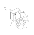
- FIG. 2 is an explanatory view of a Western-style toilet bowl 100 provided with the opening / closing member driving device 1 of FIG.
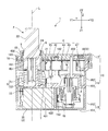
- FIG. 3 is a cross-sectional view of the opening / closing member driving device 1 of FIG.
- FIG. 4 is an exploded perspective view of the opening / closing member driving device 1 of FIG.
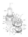
- FIG. 5 is a perspective view of the motor 3, the transmission mechanism 4, and the output shaft 2 as viewed from the other side Z2 of the first direction Z.
- the first direction Z is the direction of the axis L of the output shaft 2
- the second direction Y is the longitudinal direction of the case 10
- the third direction X is the lateral direction (width direction) of the case 10.
- one side of the first direction Z is Z1, the other side is Z2, one side of the second direction Y is Y1, the other side is Y2, one side of the third direction X is X1, and the other side is X2.
- the side where the output shaft 2 protrudes from the case 10 is the other side Z2 of the first direction Z
- the side where the output shaft 2 is arranged in the case 10 is the one side Y1 of the second direction Y.
- the opening / closing member driving device 1 shown in FIG. 1 is a device that opens / closes by rotating an opening / closing member such as a lid or a door.
- the Western-style toilet bowl 100 shown in FIG. 2 has a toilet bowl body 110, a toilet seat 120, a toilet lid 130, and a tank 140.
- the toilet seat 120 and the toilet lid 130 are respectively connected to the output shaft 2 (see FIG. 3) of the opening / closing member driving device 1.
- the toilet seat 120 and the toilet lid 130 are opening / closing members that are displaced to a closed posture that covers the toilet body 110 and an open posture that rises from the toilet body 110 due to the rotation of the output shaft 2.
- the Western-style toilet bowl 100 includes an opening / closing device 101 that opens / closes the toilet seat 120 and the toilet lid 130 with respect to the toilet bowl main body 110 by the opening / closing member driving device 1.
- the opening / closing device 101 may be configured such that only one of the toilet seat 120 and the toilet lid 130 is rotated by the opening / closing member driving device 1.
- the opening / closing member driving device 1 includes a motor 3, an output shaft 2, a transmission mechanism 4 that transmits the driving force of the motor 3 to the output shaft 2, and an assist spring 5 that urges the output shaft 2.
- the output shaft 2 includes a base 21 housed in the case 10 and a connecting shaft 22 protruding from the opening 9 of the case 10.
- An opening / closing member such as a toilet seat 120 and a toilet lid 130 shown in FIG. 2 is connected to the connecting shaft 22.
- the case 10 has an elongated shape in the second direction Y when viewed from the first direction Z, which is the axial direction of the output shaft 2.
- the opening 9 of the case 10 in which the output shaft 2 is arranged is located at one end of the second direction Y, which is the longitudinal direction of the case 10.
- Case 10 is made of resin. As shown in FIG. 1, the case 10 includes a first side wall 11 and a second side wall 12 extending parallel to the second direction Y. Further, the case 10 has a third side wall 13 connecting the ends of the other side Y2 of the first side wall 11 and the second side wall 12 in the second direction Y, and a second side wall Y of the first side wall 11 and the second side wall 12. A fourth side wall 14 connecting the ends of Y1 on one side is provided.
- the third side wall 13 extends linearly in the third direction X.
- the fourth side wall 14 has a convex shape protruding toward one side Y1 of the second direction Y.
- the fourth side wall 14 is a semicircular curved surface when viewed from the other side Z2 of the first direction Z.
- the case 10 includes a first case 15, an intermediate case 16, and a second case 17 arranged along the first direction Z.
- the first case 15 is located on one side Z1 of the first direction Z of the intermediate case 16, and the second case 17 is located on the other side Z2 of the first direction Z of the intermediate case 16.
- the case 10 is assembled by fixing the intermediate case 16 to the first case 15 and fixing the second case 17 to the intermediate case 16.
- the first case 15 includes a bottom plate 151 and a frame portion 152 extending from the outer peripheral edge of the bottom plate 151 to the other side Z2 in the first direction Z.
- the frame portion 152 constitutes an end portion of one side Z1 of the first side wall 11, the second side wall 12, the third side wall 13, and the fourth side wall 14 of the case 10.
- the motor 3 is fixed to the first case 15.
- the motor 3 includes a motor main body 30 and a rotating shaft 31 protruding from the motor main body 30.
- the rotation shaft 31 faces in a direction intersecting the axis L of the output shaft 2.
- the rotation center line L1 of the rotation axis 31 (see FIG. 4) is orthogonal to the axis line L of the output axis 2.
- the rotation shaft 31 is inclined with respect to the second direction Y (longitudinal direction of the case 10) when viewed from the first direction Z.
- the tip of the rotating shaft 31 is rotatably supported by a bearing member 32 held in the first case 15.
- the intermediate case 16 includes an intermediate plate 161 and an intermediate frame portion 162 extending from the outer peripheral edge of the intermediate plate 161 to the other side Z2 in the first direction Z.
- the intermediate frame portion 162 constitutes an intermediate portion in the first direction Z of the first side wall 11, the second side wall 12, the third side wall 13, and the fourth side wall 14 of the case 10.
- the intermediate case 16 accommodates a part of the gears constituting the transmission mechanism 4. Further, the intermediate case 16 accommodates the base 21 of the output shaft 2.
- a plate-shaped reinforcing member 18 is fixed to the end portion of the intermediate case 16 on the side of the second case 17.
- the reinforcing member 18 has a higher rigidity than the case 10.
- the reinforcing member 18 is made of metal.
- the reinforcing member 18 is provided with a reinforcing member side opening 181, and the output shaft 2 projects from the reinforcing member side opening 181 to the other side Z2 in the first direction Z.
- a potentiometer 8 is attached to the reinforcing member 18.
- the potentiometer 8 is arranged at the end portion of the second direction Y on the side opposite to the output shaft 2 (the other side Y2 of the second direction Y).
- the potentiometer 8 includes a potentiometer 81 (see FIG. 5) that meshes with one of a plurality of gears constituting the transmission mechanism 4, and a detection unit 82 (FIG. 3, FIG. 3) that detects the rotational angle position of the potentiometer 81. (See FIG. 4).
- the detection unit 82 includes a circuit board.
- the potentiometer 81 is located on one side Z1 of the first direction Z of the reinforcing member 18 and meshes with the third small diameter gear of the third gear.
- the detection unit 82 is located on the other side Z2 of the reinforcing member 18, and the circuit board is fixed to the reinforcing member 18.
- the second case 17 has a plate shape and is covered from the other side Z2 of the first direction Z to the intermediate case 16.
- the second case 17 is connected to the end portion of the first side wall 11, the second side wall 12, the third side wall 13, and the fourth side wall 14 of the case 10 on the other side Z2 of the first direction Z, and is connected to the end portion of the first side wall Z of the first direction Z.
- the reinforcing member 18 is covered from the other side Z2.
- the second case 17 includes an opening 9 that penetrates a portion that overlaps with the reinforcing member side opening 181 when viewed from the first direction Z. As shown in FIG. 3, the gap between the output shaft 2 arranged in the opening 9 and the inner peripheral surface of the opening 9 is sealed by the O-ring 19.
- the transmission mechanism 4 has a worm 40, a first gear 41, a second gear 42, a third gear 43, a fourth gear 44, and the like from the upstream side to the downstream side of the driving force transmission path.
- the output gear 45 is provided.
- the worm 40 is fixed to the outer peripheral side of the rotating shaft 31 of the motor 3.
- the worm 40 and the first gear 41 are arranged in the first case 15.
- the second gear 42, the third gear 43, the fourth gear 44, and the output gear 45 are arranged in the intermediate case 16.
- the first gear 41 includes a first large-diameter gear 411 that meshes with the worm 40, and a first small-diameter gear 412 that is coaxial with the first large-diameter gear 411 and has an outer diameter smaller than that of the first large-diameter gear 411.
- the first large-diameter gear 411 is located on one side Z1 of the first small-diameter gear 412 in the first direction Z.
- the first gear 41 is rotatably supported by a first support shaft 413 (see FIG. 4) extending in the first direction Z.
- One end portion of the first support shaft 413 is held by the bottom plate 151 of the first case 15, and the other end portion is held by the intermediate plate 161 of the intermediate case 16.
- the first gear 41 includes a torque limiter 46 that connects and disconnects the transmission of the driving force between the first large-diameter gear 411 and the first small-diameter gear 412.
- the second gear 42 includes a second large-diameter gear 421 that meshes with the first small-diameter gear 412 and a second small-diameter gear 422 that is coaxial with the second large-diameter gear 421 and has an outer diameter smaller than that of the second large-diameter gear 421. It is a compound gear provided.
- the second large-diameter gear 421 is located on one side Z1 of the first direction Z of the second small-diameter gear 422.
- the second large-diameter gear 421 meshes with the first small-diameter gear 412 via an opening 163 (see FIG. 8) provided in the intermediate plate 161 of the intermediate case 16.
- the second gear 42 is rotatably supported by a second support shaft 423 (see FIG. 5) extending in the first direction Z.
- the third gear 43 includes a third large-diameter gear 431 that meshes with the second small-diameter gear 422 and a third small-diameter gear 432 that is coaxial with the third large-diameter gear 431 and has an outer diameter smaller than that of the third large-diameter gear 431. It is a compound gear provided.
- the third large-diameter gear 431 is located on one side Z1 of the first direction Z of the third small-diameter gear 432.
- the third gear 43 is rotatably supported by a third support shaft 433 extending in the first direction Z. One end portion of the third support shaft 433 is held by the intermediate plate 161 of the intermediate case 16, and the other end portion is held by the second case 17 through the reinforcing member 18.
- the fourth gear 44 is a spur gear that meshes with the third small diameter gear 432 and the output gear 45.
- the fourth gear 44 and the output gear 45 are arranged in the second direction Y.
- the fourth gear 44 is arranged coaxially with the second gear 42 and is rotatably supported by the second support shaft 423.
- One end portion of the second support shaft 423 is held by the intermediate case 16, and the other end portion is held by the reinforcing member 18. That is, the reinforcing member 18 includes a shaft holding portion 182 (see FIG. 3) that holds the second support shaft 423 that supports the second gear 42 and the fourth gear 44.
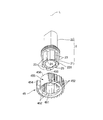
- FIG. 6 is an exploded perspective view of the output gear 45 and the output shaft 2.
- the output gear 45 is made of metal.
- a resin output shaft 2 is coaxially fixed to the output gear 45.
- the output gear 45 is an annular member provided with a center hole 451 that opens in the first direction Z.
- a plurality of recesses 452 are provided in the circumferential direction on the inner peripheral surface of the center hole 451, and a plurality of convex portions 23 fitted in the recesses 452 on the inner peripheral surface of the output gear 45 are provided on the outer peripheral surface of the base 21 of the output shaft 2. It is provided. Therefore, the output gear 45 and the output shaft 2 are connected around the axis L in a state in which they cannot rotate relative to each other.
- the output gear 45 is rotatably supported by the reinforcing member 18.
- the output gear 45 includes an annular portion 450 having no tooth portion on the outer peripheral surface at the end portion of Z2 on the other side of the first direction Z.
- the reinforcing member 18 includes an output gear receiving portion 183 that rotatably supports the annular portion 450 of the output gear from the outer peripheral side at the outer peripheral edge portion of the reinforcing member side opening 181 (see FIG. 3).
- the output gear receiving portion 183 is an annular tubular portion that bends and extends to the other side of the reinforcing member side opening 181 in the reinforcing member 18 in the first direction, and is formed by, for example, burring.
- FIG. 7 is an exploded perspective view of the output gear 45, the output shaft 2, and the assist spring 5.
- the base 21 of the output shaft 2 is a resin portion and is fixed to the output gear 45 by thermal caulking.
- FIG. 7 illustrates a state in which the output gear 45 and the output shaft 2 are assembled so as not to rotate relative to each other and before thermal caulking is performed. In the state before thermal caulking, the convex portion 23 of the output shaft 2 projects from the concave portion 452 of the output gear 45 to one side Z1 of the first direction Z.
- the tip portion 231 of the one side Z1 of the first direction Z of the convex portion 23 has a tapered shape in which the protrusion dimension to the one side Z1 of the first direction Z increases toward the outer side in the radial direction. Therefore, the tip portion 231 is largely crushed by the thermal caulking on the radial outer portion, and is crushed into a shape that expands to the radial outer side of the recess 452. As a result, the crushed resin locks the inner peripheral edge of the end face of the output gear 45, so that the output gear 45 is fixed to the output shaft 2.
- the assist spring 5 includes a first spring 51 and a second spring 52.
- the first spring 51 and the second spring 52 are torsion coil springs.
- the second spring 52 is arranged on the inner peripheral side of the first spring 51.
- the first spring 51 is located on one side Z1 of the output gear 45 in the first direction Z.
- the second spring 52 is located on one side Z1 of the first direction Z of the output shaft 2 and is located on the inner peripheral side of the first spring 51.
- the first spring 51 includes a spring portion 510 in which a wire rod 50A having a rectangular cross section is spirally wound, a first end portion 511 extending from the spring portion 510 to one side Z1 in the first direction Z, and a spring.
- a second end portion 512 extending from the portion 510 to the other side Z2 in the first direction Z is provided.
- the second end portion 512 of the first spring 51 is arranged in the notch portion 453 notched from the outer peripheral surface of the output gear 45 toward the inner peripheral side.
- the output gear 45 has teeth formed on the outer peripheral surface of the range excluding the notch 453.
- the notch 453 includes a first surface 454 provided at one end in the circumferential direction and a second surface 455 provided at the other end in the circumferential direction. As will be described later, when the output shaft 2 rotates to a predetermined angular position, the second end portion 512 comes into contact with the second surface 455. When the output shaft 2 further rotates, the output shaft 2 is urged by the first spring 51 via the output gear 45.
- FIG. 8 is a perspective view of the first case 15 and the intermediate case 16 as viewed from the other side Z2 of the first direction Z.
- the intermediate case 16 includes a support portion 6 projecting from the intermediate plate 161 to the other side Z2 in the first direction Z.
- the support portion 6 is located on the inner peripheral side of the first spring 51 and the second spring 52, and protrudes from the first spring 51 and the second spring 52 to the other side Z2 in the first direction Z. To do. That is, the first spring 51 and the second spring 52 are held by the support portion 6 and supported by the intermediate plate 161 from one side Z1 of the first direction Z.
- the motor 3 is arranged on one side Z1 of the first direction Z of the intermediate plate 161.
- the intermediate plate 161 divides the internal space of the case 10 into a lower space in which the motor 3 is arranged and an upper space in which the output shaft 2 and the assist spring 5 and the like are arranged.
- the motor 3 includes a receiving portion 33 that supports the intermediate plate 161 from one side Z1 of the first direction Z.
- the receiving portion 33 is a side surface of the motor body 30 on the other side Z2 in the first direction Z, and is composed of, for example, a metal motor case.
- the receiving portion 33 is a flat surface perpendicular to the axis L.
- the receiving portion 33 supports the intermediate plate 161 and also supports the supporting portion 6 from the side opposite to the output shaft 2 in the axis L direction (that is, one side Z1 of the first direction Z).
- the output shaft 2 and the output gear 45 are rotatably supported by the tip portion of the support portion 6.
- the output shaft 2 is provided with a circular recess 24 recessed in the other side Z2 on the end surface of one side Z1 of the first direction Z of the base 21, and the tip portion of the support portion 6 is arranged in the circular recess 24. It is in contact with the bottom surface of the circular recess 24.
- the tip of the other side Z2 of the support portion 6 in the first direction Z is a position on the inner peripheral side of the output gear receiving portion 183 of the reinforcing member 18 that rotatably supports the annular portion 450 of the output gear 45. Extends to.
- the intermediate case 16 is provided with an opening 164 that penetrates the intermediate plate 161 in the first direction Z.
- the opening 164 is an intermediate frame portion 162 of the intermediate case 16 that includes a frame portion 165 and a support portion 6 located on one side X1 of the third direction X among a pair of frame portions extending parallel to the second direction Y. It is provided in between.
- the opening 164 is provided at a position where the first end portion 511 of the first spring 51 can be arranged when the first spring 51 and the second spring 52 are mounted on the outer peripheral side of the support portion 6.
- the first case 15 is provided with a spring holding portion 153 at a position overlapping the opening 164 of the intermediate case 16 when viewed from the first direction Z.
- the spring holding portion 153 includes a spring locking hole 154 that is recessed in one side Z1 of the first direction Z.
- the first spring 51 is inserted into a spring locking hole 154 provided in the spring holding portion 153 of the first case 15 with the first end portion 511 protruding from the opening 164 of the intermediate case 16 to one side Z1 of the first direction Z. Will be done.
- the spring holding portion 153 is supported by the motor 3 from a direction intersecting the first direction Z, which is the direction in which the spring locking hole 154 opens. That is, the motor 3 includes a spring receiving portion 34 that receives the spring holding portion 153 from a direction intersecting the opening direction (first direction Z) of the spring locking hole 154. As shown in FIG. 8, the spring holding portion 153 projects from the inner surface of the frame portion 152 of the first case 15 to the side where the motor body 30 is located (the other side X2 in the third direction X). The spring holding portion 153 includes an inclined surface 155 cut out at the end of the other side X2 in the third direction X so as to be parallel to the side surface of the motor main body 30.
- the inclined surface 155 of the spring holding portion 153 is supported by the side surface of the motor body 30 from the other side X2 in the third direction X. That is, the spring receiving portion 34 is a side surface of the motor main body 30, and is composed of, for example, a metal motor case.
- the second spring 52 is bent inward in the radial direction from a spring portion 520 in which a wire rod 50B having a circular cross section is spirally wound and an end portion of one side Z1 of the first direction Z of the spring portion 520. It includes a first end portion 521 extending linearly and a second end portion 522 extending from the spring portion 520 to the other side Z2 in the first direction Z.
- the first end portion 521 of the second spring 52 is arranged in the groove portion 61 (see FIGS. 8, 9 (b) and 10 (b)) provided in the support portion 6.
- the output shaft 2 includes a spring locking hole 25 provided on the end surface of the other side Z2 of the base portion 21.
- the second end portion 522 of the second spring 52 is arranged in the spring locking hole 25 of the output shaft 2.
- the spring locking hole 25 is formed in a convex portion 23 provided on the outer peripheral surface of the base portion 21 of the output shaft 2. As shown in FIG. 7, since the convex portion 23 is fitted in the concave portion 452 provided in the output gear 45, the resin portion surrounding the spring locking hole 25 is reinforced by the metal output gear 45. .. Therefore, even if the thickness of the resin portion surrounding the spring locking hole 25 is thin, the base portion 21 of the output shaft 2 may be deformed or damaged by the load applied from the second end portion 522 inserted in the spring locking hole 25. Few.
- the intermediate case 16 includes ribs 7 extending in the circumferential direction on the outer peripheral side of the support portion 6.
- the rib 7 projects from the intermediate plate 161 to the other side Z2 in the first direction Z.
- the inner peripheral edge 71 of the rib 7 has an arc shape. That is, the inner peripheral edge 71 of the rib 7 has a shape along the outer peripheral edge of the spring portion 520 of the second spring 52, which is a spring arranged on the inner peripheral side.
- the outer peripheral edge of the rib 7 is provided with arc portions 72A and 72B along the inner circumference of the spring portion 510 of the first spring 51 at both ends in the circumferential direction, and protrudes radially outward in the center of the circumferential direction.
- a protruding portion 73 is provided.
- the protruding portion 73 has a shape that protrudes inward of the opening 164.
- the outer peripheral edge of the rib 7 is provided with straight portions 74A and 74B extending in the tangential direction of the arc portion 72 on both sides of the tip of the protruding portion 73 in the circumferential direction, respectively.
- the first spring 51 includes a linear portion 513 extending in the tangential direction of the first lap 510A from the winding start position of the first lap 510A of the spring portion 510, and the first end portion 511 , It bends and extends from the tip of the linear portion 513 to one side Z1 of the first direction Z.
- FIG. 9 is an explanatory view showing the planar shapes of the support portion 6, the rib 7, and the assist spring 5.
- the planar shape of the first spring 51 shown in FIG. 9 is the planar shape of the first circumference 510A, the linear portion 513, and the first end portion 511.
- the arc portion 72A provided at one end in the circumferential direction of the outer peripheral edge extends along the inner circumference of the winding start portion of the first circumference 510A of the spring portion 510.
- the straight portion 74A extending from the arc portion 72A to the tip of the protruding portion 73 extends along the linear portion 513.
- the first spring 51 is arranged in a state in which the winding start portion and the linear portion 513 of the first circumference 510A of the spring portion 510 extend along the outer peripheral edge of the rib 7. As a result, the protrusion 73 of the rib 7 prevents the first spring 51 from rotating, and the linear portion 513 of the first spring 51 is positioned at an angle position extending toward the opening 164.
- the rib 7 has a symmetrical shape with respect to a straight line L0 connecting the opening 164 in which the first end portion 511 is arranged and the radial center P of the support portion 6. As shown in FIG. 9, the tip of the protrusion 73 is located on the straight line L0.
- the rib 7 includes a straight portion 74A extending from the tip of the protruding portion 73 to one side in the circumferential direction and a straight portion 74B extending to the other side in the circumferential direction.
- the arc portion 72 includes an arc portion 72A extending to one side in the circumferential direction of the straight portion 74A and an arc portion 72B extending to the other side in the circumferential direction of the straight portion 74B.
- the straight line portion 74A and the arc portion 72A and the straight line portion 74B and the arc portion 72B have symmetrical shapes with respect to the straight line L0.
- the rib 7 is provided in an angle range of 180 ° about the straight line L0 as the center in the circumferential direction.
- the first spring 51 has a shape in which the linear portion 513 is guided by the linear portion 74A located on one side in the circumferential direction with respect to the tip of the protruding portion 73.
- the rotation direction of the output shaft 2 can be changed by using the first spring 51A (see FIG. 14B) whose winding direction is opposite to that of the first spring 51.
- the straight portion 74B located on the other side in the circumferential direction with respect to the tip of the protruding portion 73
- the linear portion 513A see FIG.
- the protrusion 73 can prevent the first spring 51A from rotating. That is, even when the first spring 51A in which the winding direction of the first spring 51 is reversed is attached, it is not necessary to change the shape of the rib 7.
- the protruding height of the rib 7 in the first direction Z is smaller than the wire diameter of the wire rod 50A constituting the first spring 51.
- the winding end portion of the first circumference 510A of the spring portion 510 extends in the circumferential direction on one side Z1 of the first direction Z of the protruding portion 73 of the rib. Therefore, the protruding portion 73 functions as a receiving portion that supports a part of the first spring 51 from one side Z1 of the first direction Z.
- Both ends of the rib 7 in the circumferential direction (the portions where the arc portions 72A and 72B are provided) have a tapered shape in which the width in the radial direction is not constant and the width in the radial direction becomes narrower as the distance from the protruding portion 73 in the circumferential direction increases. .. Therefore, a radial gap S is formed between the first circumference 510A of the first spring 52 and the arc portion 72A of the rib 7.
- the inner peripheral edge 71 of the rib 7 is an inclined surface in which the distance from the radial center P of the support portion 6 increases toward the other side Z2 of the first direction Z. Therefore, the second spring 52 is supported by the inner peripheral edge 71 from one side Z1 of the first direction Z.
- the assist spring 5 rotates the output shaft 2 around the axis L in the second rotation direction CCW opposite to the first rotation direction CW.
- the urging force to be made is applied to the output shaft 2. That is, when driving the opening / closing member, an assist force for urging the output shaft 2 is applied to the output shaft 2.
- the transmission mechanism 4 includes the torque limiter 46 on the first gear 41, the torque limiter 46 functions when an excessive load is applied to the transmission mechanism 4 from the opening / closing member via the output shaft 2.
- the transmission of the driving force transmission by the transmission mechanism 4 is cut off. As a result, it is possible to prevent the transmission mechanism 4 from being damaged due to an excessive load from the outside.
- the assist spring 5 has different working angle ranges (angle ranges for generating urging force) between the first spring 51 and the second spring 52.
- the load curve showing the relationship between the rotational load when rotating the opening / closing member from the open position to the closed position and the rotation angle of the output shaft 2 has a shape showing a simple proportional relationship. is not. Therefore, by combining a plurality of springs having different working angle ranges, a graph showing the relationship between the total force of the driving force of the motor 3 and the urging force of the first spring 51 and the second spring 52 and the rotation angle is shown as a load curve. Is approaching.
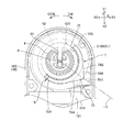
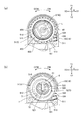
- FIG. 10 is an explanatory diagram showing a state of the assist spring 5 when the output shaft 2 is at the reference position R0.
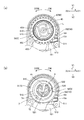
- FIG. 11 is an explanatory diagram showing a state of the assist spring 5 when the output shaft 2 is at the action start position R2 of the second spring 52.
- 10 (a) and 11 (a) show the rotation position of the output shaft 2
- FIGS. 10 (b) and 11 (b) show the state of the assist spring 5.
- FIG. 12 is an explanatory diagram showing a state of the assist spring 5 when the output shaft 2 is at the action start position R1 of the first spring 51.
- the second end portion 512 of the first spring 51 is located on one side of the notch portion 453 of the output gear 45 in the circumferential direction. , Away from the second surface 455. Therefore, no urging force is applied from the first spring 51 to the output gear 45. Further, as shown in FIG. 10B, the first end portion 521 of the second spring 52 is located at the center in the circumferential direction of the groove portion 61 provided in the support portion 6.
- the width of the groove portion 61 in the circumferential direction increases from the radial center of the support portion 6 toward the outside in the radial direction, and the first end portion 521 is in the circumferential direction within a range that does not contact the inner surface of the groove portion 61. It is a shape that can be moved. Therefore, no urging force is applied from the second spring 51 to the output shaft 2.
- the first spring 51 has a second end portion 512. Contact the second surface 455. Therefore, when the output shaft 2 further rotates in the first rotation direction CW from here, the first spring 51 is deformed to generate an urging force. From the above, the assist spring 5 does not generate an assist force from the reference position R0 to the action start position R2 of the second spring 52, and only the second spring 52 has an urging force from the action start position R2 to the action start position R1. Is generated, so that the assist force is generated by only one spring. Then, from the action start position R1, both the second spring 52 and the first spring 51 generate an urging force, so that the total becomes the assist force.
- the output shaft 2 rotates in a range from the reference position R0 to the maximum rotation position Rmax.
- the action angle range of the first spring 51 (first action angle range) is the range from the action start position R1 of the first spring 51 to the maximum rotation position Rmax.
- the action angle range of the second spring 52 (second action angle range) is a range from the action start position R2 of the second spring 52 to the maximum rotation position Rmax.
- the rotation angle of the output shaft 2 at the reference position R0 is 0 °
- the rotation angle of the output shaft 2 at the maximum rotation position Rmax is 120 °
- the rotation angle of the output shaft 2 at the action start position R1 of the first spring 51 is 120 °.
- the first working angle range is 50 ° to 120 °.
- the second action angle range is 20 ° to 120 °. Therefore, the assist force is not generated until the output shaft 2 rotates 20 ° from the reference position R0, and the urging force of the second spring 52 becomes the assist force when the rotation angle from the reference position R0 is in the range of 20 ° to 50 °.
- the rotation angle from the reference position R0 is in the range of 50 ° to 120 °
- the total urging force of the second spring 52 and the urging force of the first spring 51 are the assisting force.
- the spring constant of the first spring 51 is larger than the spring constant of the second spring 52.
- the first spring 51 is made of a wire rod 50A having a square cross section
- the second spring 52 is made of a wire rod 50B having a circular cross section
- the wire diameters of the wire rod 50A and the wire rod 50B are the same.
- the spring constant of the coil spring formed of the wire having a square cross section is larger than that of the coil spring formed of the wire having a circular cross section.
- the working angle range (first working angle range) of the first spring 51 having a large spring constant is smaller than the working angle range (second working angle range) of the second spring 52 having a small spring constant.
- the output shaft 2 deforms the assist spring 5 when rotating from the reference position R0 to the maximum rotation position Rmax to store the urging force. Therefore, when the opening / closing member such as the toilet seat or the toilet lid is driven by the opening / closing member driving device 1, the maximum rotation position Rmax is set to the origin position RA of the output shaft 2. In R0, the opening / closing member driving device 1 is installed so that the opening / closing member is located in the open position. As a result, when the load of the opening / closing member is applied as a load, the assist force acts in the direction of reducing the load.
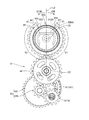
- FIG. 13 is a plan view of the transmission mechanism 4 and the output shaft 2 when the output shaft 2 is at the origin position RA.
- the origin position RA is a position where the output shaft 2 is rotated from the reference position R0 shown in FIG. 10 to the side where the assist spring 5 is deformed.
- the origin position RA is a position rotated by 120 ° from the reference position R0.
- the rotation direction from the reference position R0 to the origin position RA is the same as the winding direction of the wires 50A and 50B constituting the assist spring.
- the rotation angle of the origin position RA with respect to the reference position R0 is not limited to 120 ° and can be changed as appropriate.
- FIG. 14 is a plan view of the transmission mechanism 4, the output shaft 2, and the assist spring 5 when the output shaft 2 is rotated by the maximum angle from the origin position RA.
- FIG. 14A shows a case where the rotation direction from the origin position RA is the second rotation direction CCW.
- FIG. 14B shows a case where the rotation direction from the origin position RA is the first rotation direction CW.
- the direction in which the assist force acts can be reversed by selectively attaching one of the two types of assist springs 5 and 5A having different winding directions. As a result, as shown in FIG.
- the first form in which the assist force acts when rotating from the origin position RA to the second rotation direction CCW can be obtained, and as shown in FIG. 14 (b).
- the form of the first spring 51 shown in FIGS. 3, 5 to 7, and 10 to 12 is the form of the first spring 51 used in the first form shown in FIG. 14 (a). ..
- an assist force acts when rotating from the origin position RA to the second rotation direction CCW.
- the first spring 51 and the second spring 52 in which the wire rods 50A and 50B are wound in the first rotation direction CW from one side Z1 of the first direction Z toward the other side Z2 are used as the assist spring 5. use.
- the first spring 51A has a winding direction opposite to that of the first spring 51
- the second spring has a winding direction opposite to that of the second spring 52 (not shown). Omitted) is used as the assist spring 5A.
- the ribs 7 provided in the intermediate case 16 are provided with straight portions 74A and 74B on both sides of the protruding portion 73 in the circumferential direction, respectively.
- the linear portion 513 of the first spring 51 is guided by the linear portion 74A, and the rotation of the first spring 51 is stopped.
- the linear portion 513A (see FIG. 14B) of the first spring 51A is guided by the linear portion 74B, and the first spring 51A is prevented from rotating. That is, the intermediate case 16 is in a form capable of holding the first spring 51A whose winding direction is opposite to that of the first spring 51 without changing the shape.
- the second end portion 512 of the first spring 51 is the end of the notch portion 453 provided in the output gear 45 on the second rotation direction CCW side when storing the urging force.
- the second end portion 512A of the first spring 51A is on the first rotation direction CW side of the notch portion 453 provided in the output gear 45 when accumulating the urging force.
- FIG. 13 the engagement state of the second end portion 512 and the second surface 455 in the first form and the engagement state of the second end portion 512A and the first surface 454 in the second form are shown by broken lines.
- the output gear 45 has a first tooth portion T1 that meshes with a fourth gear 44, which is a front gear, while the output shaft 2 rotates from the origin position RA to the first rotation direction CW. Further, the output shaft 2 is provided with a second tooth portion T2 that meshes with a fourth gear 44, which is a front gear, while the output shaft 2 rotates from the origin position RA to the second rotation direction CCW opposite to the first rotation direction CW. ..
- the first tooth portion T1 and the second tooth portion T2 have a symmetrical shape with respect to a straight line L2 connecting the center C1 of the output gear 45 and the center C2 of the fourth gear 44, which is the front gear.
- the notch portion 453 is notched between the end portion of the first tooth portion T1 on the second rotation direction CCW side and the end portion of the second tooth portion T2 on the first rotation direction CW side.
- the shape is symmetrical with respect to the straight line L2 connecting the center C1 of the output gear 45 and the center C2 of the fourth gear 44, which is the front gear.
- the end portion of the first tooth portion T1 on the second rotation direction CCW side and the end portion of the second tooth portion T2 on the first rotation direction CW side are the teeth of the fourth gear 44, which are the front gears, respectively.
- a stopper 47 that interferes with the tip is provided.
- the stopper 47 includes an engaging surface 471 that abuts on the tooth tip of the fourth gear 44 from the outside in the radial direction. The rotation of the output gear 45 and the fourth gear 44 is restricted by the radial contact between the fourth gear 44 and the engaging surface 471.
- FIG. 15 is a side view of the output shaft 2, the output gear 45, and the first spring 51.
- the output gear 45 includes a first surface 454 provided at one end in the circumferential direction of the notch portion 453, and a second surface 455 provided at the other end in the circumferential direction.
- the first surface 454 includes a first relief portion 456 having a corner portion on the side where the assist spring 5 is located (one side Z1 of the first direction Z) cut out in the circumferential direction.
- the second surface 455 includes a second relief portion 457 in which a corner portion on the side where the assist spring is located (one side Z1 of the first direction Z) is cut out in the circumferential direction.
- the first spring 51 shown in FIG. 15 is a spring in the winding direction used in the first form shown in FIG. 14 (a).
- the second end portion 512 of the first spring 51 bends and extends from the winding end portion 514 of the spring portion 510 to the other side Z2 in the first direction Z.
- the second escape portion 457 is arranged. That is, the output gear 45 includes a second relief portion 457 that is cut out of a portion arranged inside the bent portion of the wire rod 50A when engaging with the first spring 51.
- the output gear 45 and the first spring 51 When the output gear 45 is engaged, the corner portion of the output gear 45 and the bent portion of the wire rod 50A interfere with each other to prevent the assist spring 5 from tilting.
- the first relief portion 456 provided on the first surface 454 is arranged inside the bent portion of the wire rod 50A when the first spring 51A whose winding direction is opposite to that of the first spring 51 is attached. It is a shape with a notched part. Therefore, when the first spring 51A whose winding direction is opposite to that of the first spring 51 is used, it is possible to prevent the assist spring 5 from tilting due to interference between the corner portion of the output gear 45 and the bent portion of the wire rod 50A. ..
- the opening / closing member driving device 1 of the present embodiment includes a case 10, an output shaft 2 protruding from the case 10, a motor 3 housed in the case 10, and a rotation of the motor 3 housed in the case 10.
- the transmission mechanism 4 includes a transmission mechanism 4 that transmits the above to the output shaft 2, an output gear 45 that rotates integrally with the output shaft 2, and a fourth gear 44 that is a front gear that meshes with the output gear 45. ..
- the output gear 45 has a first tooth portion T1 that meshes with a fourth gear 44, which is a front gear, while the output shaft 2 rotates from the origin position RA to the first rotation direction CW, and the output shaft 2 is from the origin position RA.
- the first tooth portion T1 and the second tooth portion T2 have a symmetrical shape with respect to a straight line L2 connecting the center of the output gear 45 and the center of the fourth gear 44, which is the front gear.
- the transmission mechanism 4 that transmits the rotation of the motor 3 to the output shaft 2 is the output gear 45 that rotates integrally with the output shaft 2 and the fourth gear that meshes with the output gear 45.
- a gear 44 is provided, and the first tooth portion T1 and the second tooth portion T2 of the output gear 45 are based on a straight line L2 connecting the center C1 of the output gear 45 and the center C2 of the fourth gear 44, which is a front gear. It has a symmetrical shape. Therefore, without changing the shape of the output shaft 2 and the origin position RA, only the winding direction of the assist spring 5 is changed, and only the rotation direction is different from the output shaft 2, and the rotation angles are the same. Can be made.
- the rotation direction of the output shaft 2 can be changed, and it is not necessary to assemble the output shaft 2 by adjusting the origin position RA according to the rotation direction of the output shaft 2. Therefore, the assembling work of the opening / closing member driving device 1 is easy.
- the output gear 45 has a notch 453 cut out between the end of the second rotation direction CCW of the first tooth portion T1 and the end of the first rotation direction CW of the second tooth portion T2.
- the end of the second rotation direction CCW of the first tooth portion T1 and the end of the first rotation direction CW of the second tooth portion T2 are the tooth tips of the fourth gear 44, which is the front gear, respectively.
- a stopper 47 that interferes is provided. In this way, by providing stoppers 47 at the ends of the first tooth portion T1 and the second tooth portion T2, respectively, the rotation range of the output shaft 2 in the first rotation direction CW and the second rotation direction CCW can be obtained.
- a rotation stopper can be provided to regulate the rotation range of the tooth.
- the assist spring 5 for generating an assist force for urging the output shaft 2 in the rotation direction is provided, and the assist spring 5 is arranged on the outer peripheral side of the second spring 52 and the second spring 52.
- a spring 51 is provided, and the first spring 51 includes a second end portion 512, which is a spring end portion arranged in the notch portion 453.
- the assist spring 5 can be enlarged in the radial direction. .. As a result, the assist force can be increased and the output torque can be improved.
- the output shaft 2 rotates in the first rotation direction CW, it is a spring end portion of the second surface 455 and the first spring 51 provided at the end portion of the second rotation direction CCW of the notch portion 453.
- the output shaft 2 rotates in the second rotation direction CCW by engaging with the second end portion 512 to generate an assist force, it is provided at the end of the first rotation direction CW of the notch portion 453.
- the first surface 454 and the second end 512A which is the spring end of the first spring 51A, engage with each other to generate an assist force.
- the output gear 45 has a first surface 454 provided at the end of the first rotation direction CW of the notch portion 453 and a second surface 455 provided at the end of the second rotation direction CCW.
- the first surface 454 includes a first relief portion 456 having a corner portion on the side where the assist spring 5 is located (one side Z1 of the first direction Z) cut out in the circumferential direction, and the second surface 455 provides an assist.
- a second relief portion 457 is provided with a corner portion on the side where the spring 5 is located (one side Z1 of the first direction Z) cut out in the circumferential direction.
- the output gear 45 is made of metal, there is little possibility that the output gear 45 will be deformed or damaged due to the load applied from the second end portion 512, 512A.
- the output shaft 2 includes a resin base 21 arranged in a center hole 451 provided in the output gear 45, and the output gear 45 is fixed to the base 21 by thermal caulking.
- the portion where the load is applied from the first spring 51 having a large spring constant (notch portion 453) is made of metal, and the other portion is made of resin, so that the output shaft 2 and the entire output gear 45 are metal parts. It is possible to reduce the cost of parts as compared with the case of. Further, by fixing the output shaft 2 and the output gear 45 by thermal caulking, it is possible to eliminate the rattling of the output gear 45 with respect to the output shaft 2. Therefore, the position accuracy of the output shaft 2 can be improved.
- Opening / closing member drive device 2 ... Output shaft, 3 ... Motor, 4 ... Transmission mechanism 4, 5 ... Assist spring, 6 ... Support part, 7 ... Rib, 8 ... Potential meter, 9 ... Opening, 10 ... Case, 11 ... 1st side wall, 12 ... 2nd side wall, 13 ... 3rd side wall, 14 ... 4th side wall, 15 ... 1st case, 16 ... intermediate case, 17 ... 2nd case, 18 ... reinforcing member, 19 ... O ring, 21 ... base, 22 ... connecting shaft, 23 ... convex, 24 ... circular recess, 25 ... spring locking hole, 30 ... motor body, 31 ... rotating shaft, 32 ... bearing member, 33 ...
- annular part 451 ... center hole, 452 ... recess, 453 ... notch, 454 ... 1st surface, 455 ... 2nd surface, 456 ... 1st Relief part, 457 ... Second relief part, 471 ... Engagement surface, 510A ... 1st lap, 510 ... Spring part, 511 ... 1st end part, 512, 512A ... 2nd end part, 513, 513A ... Linear part 520 ... Spring part, 521 ... 1st end part, 522 ... 2nd end part, CCW ... 2nd rotation direction, CW ... 1st rotation direction, C1 ... Center of output gear, C2 ... Center of 4th gear, L ...
Landscapes
- Engineering & Computer Science (AREA)
- General Engineering & Computer Science (AREA)
- Mechanical Engineering (AREA)
- Health & Medical Sciences (AREA)
- Public Health (AREA)
- Toilet Supplies (AREA)
- Gear Transmission (AREA)
Abstract
開閉部材駆動装置における出力軸の回転方向の変更を可能とし、且つ、組立作業の容易化を図ること。 開閉部材駆動装置1は、ケース10から突出する出力軸2と、駆動源であるモータ3と、モータ3の回転を出力軸2に伝達する伝達機構44と、出力軸2を付勢するアシストばね5を有する。伝達機構4は、出力軸2と一体に回転する出力歯車45、および、出力歯車45と噛み合う前段の歯車である第4歯車44を備えており、出力歯車45の第1歯部T1および第2歯部T2は、出力歯車45の中心C1と前段の歯車である第4歯車44の中心C2とを結ぶ直線L2を基準として対称な形状である。従って、出力軸2の形状および原点位置RAを変更することなく、アシストばね5の巻き方向の変更のみで出力軸2の回転方向を変更できる。
Description
本発明は、開閉部材が連結される出力軸と、出力軸を駆動する駆動源と、駆動源を収容するケースを備えた開閉部材駆動装置および開閉装置に関する。
洋式トイレの便座や便蓋等の開閉部材を開閉する開閉部材駆動装置として、モータ等の駆動源の回転を、輪列などの伝達機構を介して出力軸に伝達する装置が用いられる。特許文献1には、この種の開閉部材駆動装置(蓋体開閉装置)が開示される。特許文献1の蓋体開閉装置には、出力軸を付勢して開閉部材の開閉をアシストするアシストばねが組み込まれている。また、開閉部材が急に開閉された場合にモータや伝達機構に過大な負荷がかかって破損することを防止するため、トルクリミッタが組み込まれている。
特許文献1の蓋体開閉装置は、ケース内にモータおよび減速輪列が収容される。出力軸は、減速輪列の最終歯車と噛み合う歯車部と、歯車部の中心から軸線方向に延びる軸部を備えており、軸部の先端がケースの外部へ突出している。アシストばねの一端は、歯車部の端面に設けられた固定孔に係止される。アシストばねの他端は、ケースの内壁に設けられた係止部に係止される。
ここで、蓋体開閉装置の出力軸の回転方向が一方向のみである場合、設置姿勢の変更や開閉部材の開閉方向の変更に対応できない。そこで、特許文献1では、開閉部材を駆動する際の出力軸の回転方向を選択可能にするため、巻き方向が異なる2種類のアシストばねを選択的に取り付けることができる。具体的には、出力軸に、アシストばねの端部を配置するための固定孔が2箇所に設けられている。
しかしながら、出力軸の2方向への回転を可能にする構成では、回転方向に応じて出力軸の原点位置を合わせて組み立てる必要がある。また、特許文献1のように、アシストばねの巻き方向の変更に対応するように2箇所に固定孔を設けた場合には、組立時に誤った固定孔にアシストばねの端部を挿入するおそれがある。従って、組立作業が難しいという問題がある。
以上の問題点に鑑みて、本発明の課題は、開閉部材駆動装置における出力軸の回転方向の変更を可能とし、且つ、組立作業の容易化を図ることにある。
上記課題を解決するために、本発明の開閉部材駆動装置は、ケースと、前記ケースから突出する出力軸と、前記ケースに収容されるモータと、前記ケースに収容され、前記モータの回転を前記出力軸に伝達する伝達機構と、を備え、前記伝達機構は、前記出力軸と一体に回転する出力歯車、および、前記出力歯車と噛み合う前段の歯車を備え、前記出力歯車は、前記出力軸が原点位置から第1回転方向に回転する間に前記前段の歯車と噛み合う第1歯部、および、前記出力軸が前記原点位置から前記第1回転方向とは反対側の第2回転方向に回転する間に前記前段の歯車と噛み合う第2歯部を備え、前記第1歯部および前記第2歯部は、前記出力歯車の中心と前記前段の歯車の中心とを結ぶ直線を基準として対称な形状であることを特徴とする。
本発明によれば、モータの回転を出力軸に伝達する伝達機構は、出力軸と一体に回転する出力歯車、および、出力歯車と噛み合う前段の歯車を備え、出力歯車の第1歯部および第2歯部は、出力歯車の中心と前段の歯車の中心とを結ぶ直線を基準として対称な形状である。このようにすると、出力軸の形状および原点位置を変更することなく、出力軸に、回転方向のみが異なり、且つ、回転角度は同一の動作を行わせることができる。また、出力軸の回転方向に応じて原点位置を合わせて組み立てる必要がないので、組み立て作業が容易である。
本発明において、前記出力歯車は、前記第1歯部の前記第2回転方向の端部と、前記第2歯部の前記第1回転方向の端部との間を切り欠いた切欠き部を備え、前記第1歯部の前記第2回転方向の端部、および、前記第2歯部の前記第1回転方向の端部は、それぞれ、前記前段の歯車の歯先と干渉するストッパを備えることが好ましい。このように、第1歯部と第2歯部にそれぞれ、ストッパを設けることにより、出力軸の一方側への回転範囲、および、他方側への回転範囲を規制する回転止めを設けることができる。
本発明において、前記出力軸を回転方向へ付勢するアシスト力を発生させるアシストばねを有し、前記アシストばねは、前記切欠き部に配置されるばね端部を備えることが好ましい。このように、出力歯車の切欠き部にアシストばねの端部を配置することにより、アシストばねを径方向に大型化することができる。従って、アシスト力を大きくすることができ、出力トルクを向上させることができる。また、出力軸が一方側に回転する際には、切欠き部の一方側の端部とばね端部とが係合してアシスト力を発生させ、出力軸が他方側に回転する際には、切欠き部の他方側の端部とばね端部とが係合してアシスト力を発生させる。従って、アシストばねの巻き方向の変更に応じて、出力歯車の形状を変更する必要がないので、出力歯車の形状を変更せずに、アシストばねの巻き方向の変更のみで、出力軸の回転方向の変更に対応可能である。
本発明において、前記出力歯車は、前記切欠き部の周方向の一端に設けられた第1面、および、周方向の他端に設けられた第2面を備え、前記第1面は、前記アシストばねが位置する側の角部を周方向に切り欠いた第1逃げ部を備え、前記第2面は、前記アシストばねが位置する側の角部を周方向に切り欠いた第2逃げ部を備えることが好ましい。このようにすると、螺旋状に巻いた線材の巻き終わり部を軸線方向に屈曲させて出力歯車の切欠き部に配置する際、線材の屈曲部と出力歯車の角部とが干渉してアシストばねが傾くことを抑制できる。
本発明において、前記出力歯車は、金属からなることが好ましい。このようにすると、アシストばねのばね端部から加わる負荷によって出力歯車の変形や破損が発生するおそれが少ない。
本発明において、前記出力軸は、前記出力歯車に設けられた中心穴に配置される樹脂部を備え、前記出力歯車は、熱カシメによって前記樹脂部に固定されることが好ましい。このように、アシストばねのばね端部から負荷が加わる部分を金属製とし、他の部分は樹脂製とすることにより、出力軸および出力歯車全体を金属部品にする場合と比較して、部品コストを低減させることができる。また、熱カシメにより固定することで、出力軸に対する出力歯車のがたつきが発生しないので、出力軸の位置精度を高めることができる。
次に、本発明は、上記の開閉部材駆動装置を備えた開閉装置であって、前記出力軸には、前記出力軸の回転に伴って閉姿勢および開姿勢に変位する開閉部材が連結されていることを特徴とする。例えば、前記開閉部材は、便座または便蓋である。
本発明によれば、モータの回転を出力軸に伝達する伝達機構は、出力軸と一体に回転する出力歯車、および、出力歯車と噛み合う前段の歯車を備え、出力歯車の第1歯部および第2歯部は、出力歯車の中心と前段の歯車の中心とを結ぶ直線を基準として対称な形状である。このようにすると、出力軸の形状および原点位置を変更することなく、出力軸に、回転方向のみが異なり、且つ、回転角度は同一の動作を行わせることができる。また、出力軸の回転方向に応じて原点位置を合わせて組み立てる必要がないので、組み立て作業が容易である。
以下、図面を参照して、本発明の実施の形態を説明する。図1は、本発明を適用した開閉部材駆動装置1の外観斜視図である。図2は、図1の開閉部材駆動装置1を備えた洋式便器100の説明図である。図3は、図1の開閉部材駆動装置1の断面図である。図4は、図1の開閉部材駆動装置1の分解斜視図である。図5は、モータ3、伝達機構4および出力軸2を第1方向Zの他方側Z2から見た斜視図である。
本明細書において、互いに直交する3方向を、第1方向Z、第2方向Yおよび第3方向Xとする。第1方向Zは、出力軸2の軸線Lの方向であり、第2方向Yはケース10の長手方向であり、第3方向Xは、ケース10の短手方向(幅方向)である。また、第1方向Zの一方側をZ1、他方側をZ2とし、第2方向Yの一方側をY1、他方側をY2とし、第3方向Xの一方側をX1、他方側をX2とする。ケース10から出力軸2が突出する側は第1方向Zの他方側Z2であり、ケース10において出力軸2が配置される側は第2方向Yの一方側Y1である。
(全体構成)
図1に示す開閉部材駆動装置1は、蓋や扉などの開閉部材を回動させて開閉する装置である。図2に示す洋式便器100は、便器本体110、便座120、便蓋130、およびタンク140を有する。便座120および便蓋130は、それぞれ、開閉部材駆動装置1の出力軸2(図3参照)に連結される。便座120および便蓋130は、出力軸2の回転により、便器本体110に被さる閉姿勢、および、便器本体110から立ち上がる開姿勢に変位する開閉部材である。従って、洋式便器100は、開閉部材駆動装置1によって便座120および便蓋130を便器本体110に対して開閉させる開閉装置101を備えている。なお、開閉装置101は、便座120および便蓋130の一方のみを開閉部材駆動装置1によって回動させる構成であってもよい。
図1に示す開閉部材駆動装置1は、蓋や扉などの開閉部材を回動させて開閉する装置である。図2に示す洋式便器100は、便器本体110、便座120、便蓋130、およびタンク140を有する。便座120および便蓋130は、それぞれ、開閉部材駆動装置1の出力軸2(図3参照)に連結される。便座120および便蓋130は、出力軸2の回転により、便器本体110に被さる閉姿勢、および、便器本体110から立ち上がる開姿勢に変位する開閉部材である。従って、洋式便器100は、開閉部材駆動装置1によって便座120および便蓋130を便器本体110に対して開閉させる開閉装置101を備えている。なお、開閉装置101は、便座120および便蓋130の一方のみを開閉部材駆動装置1によって回動させる構成であってもよい。
図3に示すように、開閉部材駆動装置1は、モータ3と、出力軸2と、モータ3の駆動力を出力軸2に伝達する伝達機構4と、出力軸2を付勢するアシストばね5と、モータ3および伝達機構4を収容するケース10と、を有する。出力軸2は、ケース10に収容される基部21と、ケース10の開口部9から突出する連結軸22を備える。連結軸22には、図2に示す便座120、便蓋130などの開閉部材が連結される。図1に示すように、ケース10は、出力軸2の軸線方向である第1方向Zから見た場合に、第2方向Yに細長い形状を備える。出力軸2が配置されるケース10の開口部9は、ケース10の長手方向である第2方向Yの一方側の端部に位置している。
ケース10は樹脂製である。図1に示すように、ケース10は、第2方向Yに平行に延びる第1側壁11および第2側壁12を備える。また、ケース10は、第1側壁11および第2側壁12の第2方向Yの他方側Y2の端を接続する第3側壁13、および、第1側壁11および第2側壁12の第2方向Yの一方側Y1の端を接続する第4側壁14を備える。第3側壁13は、第3方向Xに直線状に延びている。第4側壁14は、第2方向Yの一方側Y1へ突出する凸形状である。本形態では、第4側壁14は第1方向Zの他方側Z2から見て半円状の湾曲面である。
図1、図3に示すように、ケース10は、第1方向Zに沿って配列された第1ケース15、中間ケース16、および第2ケース17を備える。第1ケース15は中間ケース16の第1方向Zの一方側Z1に位置し、第2ケース17は中間ケース16の第1方向Zの他方側Z2に位置する。第1ケース15に中間ケース16が固定され、第2ケース17が中間ケース16に固定されることによって、ケース10が組み立てられている。
第1ケース15は、底板151と、底板151の外周縁から第1方向Zの他方側Z2に延びる枠部152とを備える。枠部152は、ケース10の第1側壁11、第2側壁12、第3側壁13、および第4側壁14の第1方向Zの一方側Z1の端部分を構成する。第1ケース15にはモータ3が固定されている。モータ3は、モータ本体30と、モータ本体30から突出する回転軸31を備える。回転軸31は、出力軸2の軸線Lと交差する方向を向いている。本例では、回転軸31の回転中心線L1(図4参照)は、出力軸2の軸線Lと直交する。また、回転軸31は、第1方向Zから見た場合に、第2方向Y(ケース10の長手方向)に対して傾斜している。回転軸31の先端は、第1ケース15に保持される軸受部材32によって回転可能に支持されている。
中間ケース16は、中間板161と、中間板161の外周縁から第1方向Zの他方側Z2に延びる中間枠部162とを備える。中間枠部162は、ケース10の第1側壁11、第2側壁12、第3側壁13、および第4側壁14の第1方向Zの中間部分を構成する。中間ケース16には、伝達機構4を構成する複数の歯車のうちの一部の歯車が収容される。また、中間ケース16には、出力軸2の基部21が収容される。
中間ケース16における第2ケース17の側の端部分には、板状の補強部材18が固定される。補強部材18は、ケース10よりも剛性が高い。本例において、補強部材18は、金属製である。補強部材18には、補強部材側開口部181が設けられており、補強部材側開口部181からは、出力軸2が第1方向Zの他方側Z2に突出する。また、補強部材18には、ポテンショメータ8が取り付けられている。ポテンショメータ8は、第2方向Yにおいて、出力軸2とは反対側(第2方向Yの他方側Y2)の端部分に配置される。
ポテンショメータ8は、伝達機構4を構成する複数の歯車のうちのいずれかの歯車に噛合するポテンショ歯車81(図5参照)と、ポテンショ歯車81の回転角度位置を検出する検出部82(図3、図4参照)を備える。検出部82は、回路基板を備える。ポテンショ歯車81は、補強部材18の第1方向Zの一方側Z1に位置して、第3歯車の第3小径歯車に噛合する。検出部82は、補強部材18の他方側Z2に位置し、回路基板が補強部材18に固定されている。
第2ケース17は、板状であり、第1方向Zの他方側Z2から中間ケース16に被せられている。第2ケース17は、ケース10の第1側壁11、第2側壁12、第3側壁13、および第4側壁14の第1方向Zの他方側Z2の端部分に接続され、第1方向Zの他方側Z2から補強部材18を被う。第2ケース17は、第1方向Zから見て補強部材側開口部181と重なる部位を貫通する開口部9を備える。図3に示すように、開口部9に配置される出力軸2と開口部9の内周面との隙間は、Oリング19によって封止される。
図5に示すように、伝達機構4は、駆動力伝達経路の上流側から下流側に向かって、ウォーム40、第1歯車41、第2歯車42、第3歯車43、第4歯車44、および出力歯車45を備える。ウォーム40は、モータ3の回転軸31の外周側に固定されている。図4に示すように、ウォーム40および第1歯車41は、第1ケース15内に配置される。図3に示すように、第2歯車42、第3歯車43、第4歯車44、および出力歯車45は中間ケース16内に配置される。
第1歯車41は、ウォーム40に噛合する第1大径歯車411と、第1大径歯車411と同軸で第1大径歯車411よりも外径寸法が小さい第1小径歯車412を備える。第1大径歯車411は、第1小径歯車412の第1方向Zの一方側Z1に位置する。第1歯車41は、第1方向Zに延びる第1支軸413(図4参照)に回転可能に支持されている。第1支軸413は、一方の端部分が第1ケース15の底板151に保持され、他方の端部分が中間ケース16の中間板161に保持されている。第1歯車41は、第1大径歯車411と第1小径歯車412との間に駆動力の伝達を継断するトルクリミッタ46を備える。
第2歯車42は、第1小径歯車412に噛合する第2大径歯車421と、第2大径歯車421と同軸で第2大径歯車421よりも外径寸法が小さい第2小径歯車422を備える複合歯車である。第2大径歯車421は、第2小径歯車422の第1方向Zの一方側Z1に位置する。第2大径歯車421は、中間ケース16の中間板161に設けられた開口部163(図8参照)を介して第1小径歯車412に噛合する。第2歯車42は、第1方向Zに延びる第2支軸423(図5参照)に回転可能に支持される。
第3歯車43は、第2小径歯車422に噛合する第3大径歯車431と、第3大径歯車431と同軸で第3大径歯車431よりも外径寸法が小さい第3小径歯車432を備える複合歯車である。第3大径歯車431は、第3小径歯車432の第1方向Zの一方側Z1に位置する。第3歯車43は、第1方向Zに延びる第3支軸433に回転可能に支持される。第3支軸433は、一方の端部分が中間ケース16の中間板161に保持され、他方の端部分は、補強部材18を貫通して第2ケース17に保持されている。
第4歯車44は、第3小径歯車432および出力歯車45に噛合する平歯車である。第4歯車44と出力歯車45とは第2方向Yに配列されている。第4歯車44は、第2歯車42と同軸に配置されて、第2支軸423に回転可能に支持されている。第2支軸423は、一方の端部分が中間ケース16に保持され、他方の端部分が補強部材18に保持されている。すなわち、補強部材18は、第2歯車42および第4歯車44を支持する第2支軸423を保持する軸保持部182(図3参照)を備える。
図6は、出力歯車45および出力軸2の分解斜視図である。出力歯車45は金属製である。出力歯車45には、樹脂製の出力軸2が同軸に固定される。出力歯車45は、第1方向Zに開口する中心穴451を備えた環状部材である。中心穴451の内周面には周方向に複数の凹部452が設けられ、出力軸2の基部21の外周面には、出力歯車45の内周面の凹部452に嵌る複数の凸部23が設けられている。従って、出力歯車45と出力軸2とは、軸線L周りに相対回転不能な状態で連結される。
出力歯車45は、補強部材18によって、回転可能に支持されている。出力歯車45は、第1方向Zの他方側Z2の端部分に外周面に歯部を有さない円環状部450を備える。一方、補強部材18は、補強部材側開口部181の外周縁部分に、出力歯車の円環状部450を外周側から回転可能に支持する出力歯車受部183を備える(図3参照)。出力歯車受部183は、補強部材18における補強部材側開口部181の第1方向の他方側に屈曲して延びる環状筒部であり、例えば、バーリング加工により形成される。
図7は、出力歯車45、出力軸2、およびアシストばね5の分解斜視図である。出力軸2の基部21は樹脂部であり、熱カシメによって出力歯車45に固定される。図7は、出力歯車45と出力軸2とが相対回転不能に組み立てられ、熱カシメが行われる前の状態を図示している。熱カシメが行われる前の状態では、出力軸2の凸部23は、出力歯車45の凹部452から第1方向Zの一方側Z1へ突出している。凸部23の第1方向Zの一方側Z1の先端部231は、径方向外側へ向かうに従って第1方向Zの一方側Z1への突出寸法が増大するテーパ形状である。従って、先端部231は、熱カシメによって径方向外側の部分が大きく潰され、凹部452の径方向外側に拡がる形状に潰される。これにより、潰された樹脂が出力歯車45の端面の内周縁を係止するので、出力歯車45が出力軸2に対して固定される。
図3、図7に示すように、アシストばね5は、第1ばね51および第2ばね52を備える。第1ばね51および第2ばね52はねじりコイルばねである。図3に示すように、第2ばね52は、第1ばね51の内周側に配置される。第1ばね51は、出力歯車45の第1方向Zの一方側Z1に位置する。また、第2ばね52は、出力軸2の第1方向Zの一方側Z1に位置し、第1ばね51の内周側に位置する。
図7に示すように、第1ばね51は、断面矩形の線材50Aを螺旋状に巻いたばね部510と、ばね部510から第1方向Zの一方側Z1へ延びる第1端部511と、ばね部510からから第1方向Zの他方側Z2へ延びる第2端部512を備える。図5に示すように、第1ばね51の第2端部512は、出力歯車45の外周面を内周側へ切り欠いた切欠き部453に配置される。出力歯車45は、切欠き部453を除く範囲の外周面に歯部が形成されている。切欠き部453は、周方向の一端に設けられた第1面454、および、周方向の他端に設けられた第2面455を備える。後述するように、出力軸2が所定の角度位置まで回転すると、第2面455に第2端部512が接触する。さらに出力軸2が回転すると、出力歯車45を介して出力軸2が第1ばね51によって付勢される。
図8は、第1ケース15よび中間ケース16を第1方向Zの他方側Z2から見た斜視図である。図3、図8に示すように、中間ケース16は、中間板161から第1方向Zの他方側Z2へ突出する支持部6を備える。図3に示すように、支持部6は、第1ばね51および第2ばね52の内周側に位置し、第1ばね51および第2ばね52よりも第1方向Zの他方側Z2に突出する。すなわち、第1ばね51および第2ばね52は、支持部6によって保持されると共に、中間板161によって第1方向Zの一方側Z1から支持される。
本形態では、中間板161の第1方向Zの一方側Z1にモータ3が配置される。中間板161は、ケース10の内部空間をモータ3が配置される下部空間と、出力軸2およびアシストばね5等が配置される上部空間とに区画する。モータ3は、中間板161を第1方向Zの一方側Z1から支持する受け部33を備える。受け部33は、モータ本体30の第1方向Zの他方側Z2の側面であり、例えば、金属製のモータケースによって構成される。本形態では、モータ本体30は断面角型であるため、受け部33は軸線Lに対して垂直な平坦面である。受け部33は、中間板161を支持すると共に、出力軸2とは軸線L方向で反対側(すなわち、第1方向Zの一方側Z1)から支持部6を支持している。
出力軸2および出力歯車45は、支持部6の先端部分によって回転可能に支持される。出力軸2は、基部21の第1方向Zの一方側Z1の端面に他方側Z2に窪む円形凹部24が設けられており、支持部6は、その先端部分が円形凹部24に配置され、円形凹部24の底面に接触している。ここで、支持部6の第1方向Zの他方側Z2の先端は、出力歯車45の円環状部450を回転可能に支持している補強部材18の出力歯車受部183の内周側の位置まで延びている。
図8に示すように、中間ケース16には、中間板161を第1方向Zに貫通する開口部164が設けられている。開口部164は、中間ケース16の中間枠部162において、第2方向Yに平行に延びる一対の枠部分のうち、第3方向Xの一方側X1に位置する枠部分165と支持部6との間に設けられている。開口部164は、支持部6の外周側に第1ばね51および第2ばね52を装着した場合に、第1ばね51の第1端部511を配置可能な位置に設けられている。また、第1ケース15には、第1方向Zから見て中間ケース16の開口部164と重なる位置にばね保持部153が設けられている。ばね保持部153は、第1方向Zの一方側Z1に窪むばね係止穴154を備える。第1ばね51は、第1端部511が中間ケース16の開口部164から第1方向Zの一方側Z1に突出し、第1ケース15のばね保持部153に設けられたばね係止穴154に挿入される。
第1ケース15において、ばね保持部153は、ばね係止穴154が開口する方向である第1方向Zと交差する方向からモータ3によって支持される。すなわち、モータ3は、ばね係止穴154の開口方向(第1方向Z)と交差する方向からばね保持部153を受けるばね受け部34を備える。図8に示すように、ばね保持部153は、第1ケース15の枠部152の内面からモータ本体30が位置する側(第3方向Xの他方側X2)へ突出する。ばね保持部153は、第3方向Xの他方側X2の端部にモータ本体30の側面と平行になるように切り欠かれた傾斜面155を備える。第1ケース15にモータ3を収容すると、ばね保持部153の傾斜面155がモータ本体30の側面によって第3方向Xの他方側X2から支持される。すなわち、ばね受け部34は、モータ本体30の側面であり、例えば、金属製のモータケースによって構成される。
図7に示すように、第2ばね52は、断面円形の線材50Bを螺旋状に巻いたばね部520と、ばね部520の第1方向Zの一方側Z1の端部から径方向内側へ屈曲して直線状に延びる第1端部521と、ばね部520から第1方向Zの他方側Z2へ延びる第2端部522を備える。第2ばね52の第1端部521は、支持部6に設けられた溝部61(図8、図9(b)、図10(b)参照)に配置される。これにより、第2ばね52の第1端部521が中間ケース16に係止される。また、図7に示すように、出力軸2は、基部21の他方側Z2の端面に設けられたばね係止穴25を備える。第2ばね52の第2端部522は、出力軸2のばね係止穴25に配置される。
ばね係止穴25は、出力軸2の基部21の外周面に設けられた凸部23に形成されている。図7に示すように、凸部23は、出力歯車45に設けられた凹部452に嵌まっているので、ばね係止穴25を囲む樹脂部分は、金属製の出力歯車45によって補強されている。従って、ばね係止穴25を囲む樹脂部分の肉厚が薄くても、ばね係止穴25に挿入された第2端部522から加わる荷重によって出力軸2の基部21が変形あるいは破損するおそれが少ない。
(リブ形状)
図8に示すように、中間ケース16は、支持部6の外周側において周方向に延びるリブ7を備える。リブ7は、中間板161から第1方向Zの他方側Z2へ突出する。支持部6の外周側に第1ばね51および第2ばね52を装着したとき、リブ7の周方向の一端は、第1ばね51と第2ばね52との間に配置される(図3参照)。リブ7の内周縁71は円弧状である。すなわち、リブ7の内周縁71は、内周側に配置されるばねである第2ばね52のばね部520の外周に沿う形状である。一方、リブ7の外周縁は、周方向の両端にそれぞれ、第1ばね51のばね部510の内周に沿う円弧部72A、72Bが設けられ、周方向の中央に、径方向外側へ突出する突出部73が設けられている。突出部73は、開口部164の内側へ突出する形状になっている。また、リブ7の外周縁は、突出部73の先端の周方向の両側にそれぞれ、円弧部72の接線方向に延びる直線部74A、74Bが設けられている。
図8に示すように、中間ケース16は、支持部6の外周側において周方向に延びるリブ7を備える。リブ7は、中間板161から第1方向Zの他方側Z2へ突出する。支持部6の外周側に第1ばね51および第2ばね52を装着したとき、リブ7の周方向の一端は、第1ばね51と第2ばね52との間に配置される(図3参照)。リブ7の内周縁71は円弧状である。すなわち、リブ7の内周縁71は、内周側に配置されるばねである第2ばね52のばね部520の外周に沿う形状である。一方、リブ7の外周縁は、周方向の両端にそれぞれ、第1ばね51のばね部510の内周に沿う円弧部72A、72Bが設けられ、周方向の中央に、径方向外側へ突出する突出部73が設けられている。突出部73は、開口部164の内側へ突出する形状になっている。また、リブ7の外周縁は、突出部73の先端の周方向の両側にそれぞれ、円弧部72の接線方向に延びる直線部74A、74Bが設けられている。
図7に示すように、第1ばね51は、ばね部510の1周目510Aの巻き始め位置から1周目510Aの接線方向へ延びる直線状部分513を備えており、第1端部511は、直線状部分513の先端から第1方向Zの一方側Z1へ屈曲して延びている。
図9は、支持部6、リブ7、およびアシストばね5の平面形状を示す説明図である。図9に示す第1ばね51の平面形状は、1周目510A、直線状部分513、および第1端部511の平面形状である。中間ケース16に設けられたリブ7は、外周縁の周方向の一方側の端部に設けられた円弧部72Aが、ばね部510の1周目510Aの巻き始め部分の内周に沿って延びている。また、円弧部72Aから突出部73の先端まで延びる直線部74Aは、直線状部分513に沿って延びている。第1ばね51は、ばね部510の1周目510Aの巻き始め部分および直線状部分513がリブ7の外周縁に沿って延びる状態に配置される。これにより、リブ7の突出部73によって第1ばね51の回り止めがなされるとともに、第1ばね51の直線状部分513が開口部164へ向かって延びる角度位置に位置決めされる。
リブ7は、第1端部511が配置される開口部164と、支持部6の径方向の中心Pとを結ぶ直線L0を基準として対称な形状である。図9に示すように、突出部73の先端は直線L0上に位置する。リブ7は、突出部73の先端から周方向の一方側へ延びる直線部74A、および、周方向の他方側へ延びる直線部74Bを備える。また、円弧部72は、直線部74Aの周方向の一方側へ延びる円弧部72Aと、直線部74Bの周方向の他方側へ延びる円弧部72Bを備える。つまり、直線部74Aおよび円弧部72Aと、直線部74Bおよび円弧部72Bとは、直線L0を基準として対称な形状である。リブ7は、直線L0を周方向の中心とする180°の角度範囲に設けられている。
図9に示すように、第1ばね51は、突出部73の先端に対して周方向の一方側に位置する直線部74Aによって直線状部分513がガイドされる形状である。後述するように、本形態では、第1ばね51とは巻き方向が逆の第1ばね51A(図14(b)参照)を使用することによって、出力軸2の回転方向の変更を可能にしている。すなわち、本形態のリブ7は、第1ばね51とは巻き方向が逆の第1ばね51Aを取り付ける場合には、突出部73の先端に対して周方向の他方側に位置する直線部74Bによって第1ばね51Aの直線状部分513A(図14(b)参照)をガイドすると共に、突出部73によって第1ばね51Aの回り止めを行うことができる。つまり、第1ばね51の巻き方向を逆向きにした第1ばね51Aを取り付ける場合でもリブ7の形状を変更する必要がない。
リブ7の第1方向Zの突出高さは、第1ばね51を構成する線材50Aの線径よりも小さい。第1ばね51は、ばね部510の1周目510Aの巻き終り部分が、リブの突出部73の第1方向Zの一方側Z1において周方向に延在する。従って、突出部73は、第1ばね51の一部を第1方向Zの一方側Z1から支持する受け部として機能している。
リブ7の周方向の両端(円弧部72A、72Bが設けられた部分)は、径方向の幅が一定ではなく、突出部73から周方向で離れるに従って径方向の幅が細くなる先細り形状である。そのため、第1ばね52の1周目510Aとリブ7の円弧部72Aとの間には、径方向の隙間Sが形成されている。
また、リブ7の内周縁71は、第1方向Zの他方側Z2へ向かうに従って支持部6の径方向の中心Pからの距離が増大する傾斜面になっている。そのため、第2ばね52は、内周縁71によって第1方向Zの一方側Z1から支持される。
(動作)
開閉部材駆動装置1は、モータ3が正方向あるいは逆方向に駆動されると、モータ3の駆動力が伝達機構4を介して出力軸2に伝達され、出力軸2が第1回転方向CWあるいは第2回転方向CCWに回転する。これにより、出力軸2に固定された便座、便蓋などの開閉部材は、開方向あるいは閉方向に回転する。開閉部材が回転すると、ポテンショメータ8からは、開閉部材の位置に対応する信号が出力される。また、出力軸2に連結された開閉部材が第1回転方向CWに回転すると、アシストばね5は、出力軸2を軸線L周りで第1回転方向CWとは反対の第2回転方向CCWに回転させる付勢力を出力軸2に加える。つまり、開閉部材を駆動する際に、出力軸2を付勢するアシスト力が出力軸2に加えられる。また、伝達機構4は、第1歯車41にトルクリミッタ46を備えているので、開閉部材から出力軸2を介して伝達機構4に過大な負荷が加わった場合には、トルクリミッタ46が機能して、伝達機構4による駆動力伝達の伝達を遮断する。これにより、外部からの過大な負荷に起因して、伝達機構4が破損することを防止できる。
開閉部材駆動装置1は、モータ3が正方向あるいは逆方向に駆動されると、モータ3の駆動力が伝達機構4を介して出力軸2に伝達され、出力軸2が第1回転方向CWあるいは第2回転方向CCWに回転する。これにより、出力軸2に固定された便座、便蓋などの開閉部材は、開方向あるいは閉方向に回転する。開閉部材が回転すると、ポテンショメータ8からは、開閉部材の位置に対応する信号が出力される。また、出力軸2に連結された開閉部材が第1回転方向CWに回転すると、アシストばね5は、出力軸2を軸線L周りで第1回転方向CWとは反対の第2回転方向CCWに回転させる付勢力を出力軸2に加える。つまり、開閉部材を駆動する際に、出力軸2を付勢するアシスト力が出力軸2に加えられる。また、伝達機構4は、第1歯車41にトルクリミッタ46を備えているので、開閉部材から出力軸2を介して伝達機構4に過大な負荷が加わった場合には、トルクリミッタ46が機能して、伝達機構4による駆動力伝達の伝達を遮断する。これにより、外部からの過大な負荷に起因して、伝達機構4が破損することを防止できる。
(アシストばねの作用角度範囲)
アシストばね5は、第1ばね51と第2ばね52の作用角度範囲(付勢力を発生させる角度範囲)が異なる。開閉部材が便座や便蓋である場合に、開閉部材を開位置から閉位置まで回転させる際の回転負荷と出力軸2の回転角度との関係を示す負荷曲線は、単純な比例関係を示す形状ではない。そこで、作用角度範囲が異なる複数のばねを組み合わせることにより、モータ3の駆動力と第1ばね51および第2ばね52による付勢力とを合計した力と回転角度との関係を示すグラフを負荷曲線に近づけている。
アシストばね5は、第1ばね51と第2ばね52の作用角度範囲(付勢力を発生させる角度範囲)が異なる。開閉部材が便座や便蓋である場合に、開閉部材を開位置から閉位置まで回転させる際の回転負荷と出力軸2の回転角度との関係を示す負荷曲線は、単純な比例関係を示す形状ではない。そこで、作用角度範囲が異なる複数のばねを組み合わせることにより、モータ3の駆動力と第1ばね51および第2ばね52による付勢力とを合計した力と回転角度との関係を示すグラフを負荷曲線に近づけている。
図10は、出力軸2が基準位置R0にあるときのアシストばね5の状態を示す説明図である。図11は、出力軸2が第2ばね52の作用開始位置R2にあるときのアシストばね5の状態を示す説明図である。図10(a)、図11(a)は出力軸2の回転位置を示し、図10(b)、図11(b)はアシストばね5の状態を示す。図12は、出力軸2が第1ばね51の作用開始位置R1にあるときのアシストばね5の状態を示す説明図である。
図10(a)に示すように、出力軸2が基準位置R0にあるとき、第1ばね51は、第2端部512が出力歯車45の切欠き部453の周方向の一方寄りに位置し、第2面455から離れている。従って、第1ばね51から出力歯車45へ付勢力は加わらない。また、図10(b)に示すように、支持部6に設けられた溝部61の周方向の中央に第2ばね52の第1端部521が位置する。溝部61は、支持部6の径方向の中心から径方向外側へ向かうに従って周方向の幅(溝幅)が大きくなっており、溝部61の内面と接触しない範囲で第1端部521が周方向に動ける形状である。従って、第2ばね51から出力軸2へ付勢力は加わらない。
図11(a)に示すように、出力軸2が第2ばね52の作用開始位置R2まで第1回転方向CWに回転すると、第1ばね51は、第2端部512が第2面455に近づくが、まだ第2面455から離れている。従って、第1ばね51から出力歯車45へ付勢力は加わらない。一方、図11(b)に示すように、第2ばね52は、出力軸2の回転に伴って第1端部521が溝部61内で第1回転方向CWに傾き、溝部61の内面と接触している。従って、ここからさらに出力軸2が第1回転方向CWに回転した場合には、第2ばね52が変形して付勢力を発生させることになる。
次に、図12に示すように、出力軸2がさらに第1回転方向CWに回転して、第1ばね51の作用開始位置R1に至ると、第1ばね51は、第2端部512が第2面455に接触する。従って、ここからさらに出力軸2が第1回転方向CWに回転した場合には、第1ばね51が変形して付勢力を発生させることになる。以上より、アシストばね5は、基準位置R0から第2ばね52の作用開始位置R2まではアシスト力を発生させず、作用開始位置R2から作用開始位置R1までは、第2ばね52のみが付勢力を発生させるので、1つのばねのみでアシスト力を発生させる。そして、作用開始位置R1からは、第2ばね52と第1ばね51の両方が付勢力を発生させるので、その合計がアシスト力となる。
本形態において、開閉部材が開位置から閉位置まで移動する際、出力軸2は、基準位置R0から最大回転位置Rmaxまでの範囲を回転する。この場合に、第1ばね51の作用角度範囲(第1作用角度範囲)は、第1ばね51の作用開始位置R1から最大回転位置Rmaxまでの範囲である。また、第2ばね52の作用角度範囲(第2作用角度範囲)は、第2ばね52の作用開始位置R2から最大回転位置Rmaxまでの範囲である。例えば、基準位置R0における出力軸2の回転角度を0°とし、最大回転位置Rmaxにおける出力軸2の回転角度が120°であり、第1ばね51の作用開始位置R1における出力軸2の回転角度が50°である場合には、第1作用角度範囲は50°~120°である。また、第2ばね52の作用開始位置R1における出力軸2の回転角度が20°である場合には、第2作用角度範囲は、20°~120°である。従って、出力軸2が基準位置R0から20°回転するまではアシスト力が発生せず、基準位置R0からの回転角度が20°~50°の範囲では第2ばね52の付勢力がアシスト力となり、基準位置R0からの回転角度が50°~120°の範囲では第2ばね52の付勢力と第1ばね51の付勢力合計がアシスト力となる。
アシストばね5は、第1ばね51のばね定数が第2ばね52のばね定数より大きい。第1ばね51は断面角型の線材50Aからなり、第2ばね52は断面円形の線材50Bからなり、線材50A、線材50Bの線径は同一である。線径が同一である場合には、断面円形の線材によって形成されるコイルばねより、断面角型の線材によって形成されるコイルばねの方が、ばね定数は大きい。
また、アシストばね5は、ばね定数が大きい第1ばね51の作用角度範囲(第1作用角度範囲)が、ばね定数が小さい第2ばね52の作用角度範囲(第2作用角度範囲)より小さい。上記のように、第1ばね51の作用開始位置R1が50°、第2ばね52の作用開始位置R2が20°である場合には、閉位置から開位置まで開閉部材を回転させる際に、ばね定数が小さい第2ばね52の方が先に付勢力を発生させ始める。
(出力軸の回転方向の変更への対応)
図10~図12を参照して説明したように、出力軸2は、基準位置R0から最大回転位置Rmaxに向けて回転する際にアシストばね5を変形させて付勢力を蓄える。従って、開閉部材駆動装置1によって便座や便蓋などの開閉部材を駆動する際、最大回転位置Rmaxを出力軸2の原点位置RAとし、原点位置RAでは開閉部材が閉位置に位置し、基準位置R0では開閉部材が開位置に位置する状態となるように開閉部材駆動装置1を設置する。これにより、開閉部材の荷重が負荷として加わる状態において、負荷を軽減する方向にアシスト力が作用する。
図10~図12を参照して説明したように、出力軸2は、基準位置R0から最大回転位置Rmaxに向けて回転する際にアシストばね5を変形させて付勢力を蓄える。従って、開閉部材駆動装置1によって便座や便蓋などの開閉部材を駆動する際、最大回転位置Rmaxを出力軸2の原点位置RAとし、原点位置RAでは開閉部材が閉位置に位置し、基準位置R0では開閉部材が開位置に位置する状態となるように開閉部材駆動装置1を設置する。これにより、開閉部材の荷重が負荷として加わる状態において、負荷を軽減する方向にアシスト力が作用する。
図13は、出力軸2が原点位置RAにあるときの伝達機構4および出力軸2の平面図である。上記のように、原点位置RAは、図10に示した基準位置R0からアシストばね5を変形させる側に出力軸2を回転させた位置である。例えば、本形態では、基準位置R0から120°回転した位置が原点位置RAである。また、基準位置R0から原点位置RAへ向かう回転方向は、アシストばねを構成する線材50A、50Bの巻き方向と同一の回転方向である。なお、基準位置R0に対する原点位置RAの回転角度は、120°に限定されず、適宜変更可能である。
図14は、出力軸2が原点位置RAから最大角度回転したときの伝達機構4、出力軸2、およびアシストばね5の平面図である。図14(a)は原点位置RAからの回転方向が第2回転方向CCWである場合を示す。また、図14(b)は、原点位置RAからの回転方向が第1回転方向CWである場合を示す。本形態の開閉部材駆動装置1は、巻き方向が異なる2種類のアシストばね5、5Aのいずれか一方を選択的に取り付けることによって、アシスト力が作用する方向を逆向きにすることができる。これにより、図14(a)に示すように、原点位置RAから第2回転方向CCWに回転する際にアシスト力が作用する第1形態とすることもできるし、図14(b)に示すように、原点位置RAから第1回転方向CWに回転する際にアシスト力が作用する第2形態とすることもできる。
本明細書において、図3、図5~7、図10~図12に示した第1ばね51の形態は、図14(a)に示す第1形態で使用する第1ばね51の形態である。第1形態では、原点位置RAから第2回転方向CCWに回転する際にアシスト力が作用する。また、第1形態では、第1方向Zの一方側Z1から他方側Z2に向かうに従って線材50A、50Bが第1回転方向CWに巻かれた第1ばね51および第2ばね52をアシストばね5として使用する。一方、図14(b)に示す第2形態では、上記の第1ばね51とは巻き方向が逆の第1ばね51A、および、第2ばね52とは巻き方向が逆の第2ばね(図示省略)をアシストばね5Aとして使用する。図9を参照して説明したように、中間ケース16に設けられたリブ7には、突出部73の周方向の両側にそれぞれ、直線部74A、74Bが設けられている。第1形態では、直線部74Aによって第1ばね51の直線状部分513がガイドされると共に、第1ばね51の回り止めがなされる。また、第2形態では、直線部74Bによって第1ばね51Aの直線状部分513A(図14(b)参照)がガイドされると共に、第1ばね51Aの回り止めがなされる。つまり、中間ケース16は、形状を変更することなく、第1ばね51とは巻き方向が逆の第1ばね51Aを保持することが可能な形態である。
図14(a)に示す第1形態では、第1ばね51の第2端部512は、付勢力を蓄える際、出力歯車45に設けられた切欠き部453の第2回転方向CCW側の端部に位置する第2面455に係合する。一方、図14(b)に示す第2形態では、第1ばね51Aの第2端部512Aは、付勢力を蓄える際、出力歯車45に設けられた切欠き部453の第1回転方向CW側の端部に位置する第1面454に係合する。図13において、第1形態における第2端部512と第2面455との係合状態、および、第2形態における第2端部512Aと第1面454との係合状態を破線で示す。
図13、図14に示すように、出力歯車45は、出力軸2が原点位置RAから第1回転方向CWに回転する間に前段の歯車である第4歯車44と噛み合う第1歯部T1、および、出力軸2が原点位置RAから第1回転方向CWとは反対側の第2回転方向CCWに回転する間に前段の歯車である第4歯車44と噛み合う第2歯部T2を備えている。第1歯部T1および第2歯部T2は、出力歯車45の中心C1と前段の歯車である第4歯車44の中心C2とを結ぶ直線L2を基準として対称な形状である。
このように、第1歯部T1および第2歯部T2が直線L2を基準として対称な形状である場合には、図14(a)に示す第1の形態、および、図14(b)に示す第2の形態のどちらを採用する場合も出力軸2の原点位置RAは同一である。従って、本形態では、出力軸2の回転方向に応じて出力軸2の原点位置を変更する必要がない。
出力歯車45において、切欠き部453は、第1歯部T1の第2回転方向CCW側の端部、および、第2歯部T2の第1回転方向CW側の端部との間を切り欠いた部分であり、出力歯車45の中心C1と前段の歯車である第4歯車44の中心C2とを結ぶ直線L2を基準として対称な形状である。また、第1歯部T1の第2回転方向CCW側の端部、および、第2歯部T2の第1回転方向CW側の端部は、それぞれ、前段の歯車である第4歯車44の歯先と干渉するストッパ47を備えている。ストッパ47は、第4歯車44の歯先に対して径方向外側から当接する係合面471を備える。第4歯車44と係合面471とが径方向に当たることによって出力歯車45と第4歯車44の回転が規制される。
図15は、出力軸2、出力歯車45および第1ばね51の側面図である。上記のように、出力歯車45は、切欠き部453の周方向の一端に設けられた第1面454、および、周方向の他端に設けられた第2面455を備える。第1面454は、アシストばね5が位置する側(第1方向Zの一方側Z1)の角部を周方向に切り欠いた第1逃げ部456を備える。また、第2面455は、アシストばねが位置する側(第1方向Zの一方側Z1)の角部を周方向に切り欠いた第2逃げ部457を備える。
図15に示す第1ばね51は、図14(a)に示した第1形態で使用される巻き方向のばねである。第1形態では、第1ばね51の第2端部512は、ばね部510の巻き終り部分514から第1方向Zの他方側Z2へ屈曲して延びている。出力軸2が第1回転方向CWに回転して第2端部512が第2面455に当接する状態になると、巻き終り部分514と第2端部512とによって形成される屈曲部分の内側に第2逃げ部457が配置される。すなわち、出力歯車45は、第1ばね51と係合する際に線材50Aの屈曲部分の内側に配置される部分を切り欠いた第2逃げ部457を備えている、従って、第1ばね51と出力歯車45とが係合する際に出力歯車45の角部と線材50Aの屈曲部分とが干渉してアシストばね5が傾くことが抑制される。同様に、また、第1面454に設けられた第1逃げ部456は、第1ばね51とは巻き方向が逆の第1ばね51Aを取り付けた場合に、線材50Aの屈曲部分の内側に配置される部分を切り欠いた形状である。従って、第1ばね51とは巻き方向が逆の第1ばね51Aを使用した場合に、出力歯車45の角部と線材50Aの屈曲部分とが干渉してアシストばね5が傾くことが抑制される。
(本形態の主な効果)
以上説明したように、本形態の開閉部材駆動装置1は、ケース10と、ケース10から突出する出力軸2と、ケース10に収容されるモータ3と、ケース10に収容され、モータ3の回転を出力軸2に伝達する伝達機構4と、を備え、伝達機構4は、出力軸2と一体に回転する出力歯車45、および、出力歯車45と噛み合う前段の歯車である第4歯車44を備える。出力歯車45は、出力軸2が原点位置RAから第1回転方向CWに回転する間に前段の歯車である第4歯車44と噛み合う第1歯部T1、および、出力軸2が原点位置RAから第1回転方向CWとは反対側の第2回転方向CCWに回転する間に前段の歯車である第4歯車44と噛み合う第2歯部T2を備える。第1歯部T1および第2歯部T2は、出力歯車45の中心と前段の歯車である第4歯車44の中心とを結ぶ直線L2を基準として対称な形状である
以上説明したように、本形態の開閉部材駆動装置1は、ケース10と、ケース10から突出する出力軸2と、ケース10に収容されるモータ3と、ケース10に収容され、モータ3の回転を出力軸2に伝達する伝達機構4と、を備え、伝達機構4は、出力軸2と一体に回転する出力歯車45、および、出力歯車45と噛み合う前段の歯車である第4歯車44を備える。出力歯車45は、出力軸2が原点位置RAから第1回転方向CWに回転する間に前段の歯車である第4歯車44と噛み合う第1歯部T1、および、出力軸2が原点位置RAから第1回転方向CWとは反対側の第2回転方向CCWに回転する間に前段の歯車である第4歯車44と噛み合う第2歯部T2を備える。第1歯部T1および第2歯部T2は、出力歯車45の中心と前段の歯車である第4歯車44の中心とを結ぶ直線L2を基準として対称な形状である
本形態では、このように、モータ3の回転を出力軸2に伝達する伝達機構4が、出力軸2と一体に回転する出力歯車45、および、出力歯車45と噛み合う前段の歯車である第4歯車44を備えており、出力歯車45の第1歯部T1および第2歯部T2は、出力歯車45の中心C1と前段の歯車である第4歯車44の中心C2とを結ぶ直線L2を基準として対称な形状である。このため、出力軸2の形状および原点位置RAを変更することなく、アシストばね5の巻き方向の変更のみで、出力軸2に、回転方向のみが異なり、且つ、回転角度は同一の動作を行わせることができる。これにより、出力軸2の回転方向の変更が可能となり、且つ、出力軸2の回転方向に応じて原点位置RAを合わせて出力軸2を組み立てる必要がない。従って、開閉部材駆動装置1の組み立て作業が容易である。
本形態では、出力歯車45は、第1歯部T1の第2回転方向CCWの端部と、第2歯部T2の第1回転方向CWの端部との間を切り欠いた切欠き部453を備える。そして、第1歯部T1の第2回転方向CCWの端部、および、第2歯部T2の第1回転方向CWの端部は、それぞれ、前段の歯車である第4歯車44の歯先と干渉するストッパ47を備えている。このようい、第1歯部T1と第2歯部T2の端部にそれぞれ、ストッパ47を設けることにより、出力軸2の第1回転方向CWへの回転範囲、および、第2回転方向CCWへの回転範囲を規制する回転止めを設けることができる。
本形態では、出力軸2を回転方向へ付勢するアシスト力を発生させるアシストばね5を有し、アシストばね5は、第2ばね52、および、第2ばね52の外周側に配置される第1ばね51を備えており、第1ばね51は、切欠き部453に配置されるばね端部である第2端部512を備える。このように、出力歯車45の歯部の周方向の一部を切り欠いた切欠き部453にアシストばね5の端部を配置することにより、アシストばね5を径方向に大型化することができる。これにより、アシスト力を大きくすることができ、出力トルクを向上させることができる。また、出力軸2が第1回転方向CWに回転する際には、切欠き部453の第2回転方向CCWの端部に設けられた第2面455と第1ばね51のばね端部である第2端部512とが係合してアシスト力を発生させ、出力軸2が第2回転方向CCWに回転する際には、切欠き部453の第1回転方向CWの端部に設けられた第1面454と、第1ばね51Aのばね端部である第2端部512Aとが係合してアシスト力を発生させる。従って、アシストばね5の巻き方向の変更に応じて、出力軸45側のばね端部の係合箇所の形状を変更する必要がないので、アシストばね5の巻き方向の変更のみで、出力軸2の回転方向の変更に対応可能である。
本形態では、出力歯車45は、切欠き部453の第1回転方向CWの端部に設けられた第1面454、および、第2回転方向CCWの端部に設けられた第2面455を備え、第1面454は、アシストばね5が位置する側(第1方向Zの一方側Z1)の角部を周方向に切り欠いた第1逃げ部456を備え、第2面455は、アシストばね5が位置する側(第1方向Zの一方側Z1)の角部を周方向に切り欠いた第2逃げ部457を備える。従って、螺旋状に巻いた線材50Aの巻き終わり部を第1方向Zに屈曲させて出力歯車45の切欠き部453に配置する場合に、線材50Aの屈曲部分と出力歯車45の角部とが干渉してアシストばね5が傾くことを抑制できる。
本形態では、出力歯車45が金属からなるため、第2端部512、512Aから加わる負荷によって出力歯車45の変形や破損が発生するおそれが少ない。
本形態では、出力軸2は、出力歯車45に設けられた中心穴451に配置される樹脂製の基部21を備え、出力歯車45は、熱カシメによって基部21に固定される。このように、ばね定数が大きい第1ばね51から負荷が加わる部分(切欠き部453)を金属製とし、他の部分は樹脂製とすることにより、出力軸2および出力歯車45全体を金属部品にする場合と比較して、部品コストを低減させることができる。また、熱カシメにより出力軸2と出力歯車45とを固定することにより、出力軸2に対する出力歯車45のがたつきをなくすことができる。従って、出力軸2の位置精度を高めることができる。
1…開閉部材駆動装置、2…出力軸、3…モータ、4…伝達機構4、5…アシストばね、6…支持部、7…リブ、8…ポテンショメータ、9…開口部、10…ケース、11…第1側壁、12…第2側壁、13…第3側壁、14…第4側壁、15…第1ケース、16…中間ケース、17…第2ケース、18…補強部材、19…Oリング、21…基部、22…連結軸、23…凸部、24…円形凹部、25…ばね係止穴、30…モータ本体、31…回転軸、32…軸受部材、33…受け部、34…ばね受け部、40…ウォーム、41…第1歯車、42…第2歯車、43…第3歯車、44…第4歯車、45…出力歯車、46…トルクリミッタ、47…ストッパ、50A…線材、50B…線材、61…溝部、71…内周縁、72A、72B…円弧部、73…突出部、74A、74B…直線部、81…ポテンショ歯車、82…検出部、100…洋式便器、101…開閉装置、110…便器本体、120…便座、130…便蓋、140…タンク、151…底板、152…枠部、153…ばね保持部、154…ばね係止穴、155…傾斜面、161…中間板、162…中間枠部、163…開口部、164…開口部、165…枠部分、181…補強部材側開口部、182…軸保持部、183…出力歯車受部、231…先端部、411…第1大径歯車、412…第1小径歯車、413…第1支軸、421…第2大径歯車、422…第2小径歯車、423…第2支軸、431…第3大径歯車、432…第3小径歯車、433…第3支軸、450…円環状部、451…中心穴、452…凹部、453…切欠き部、454…第1面、455…第2面、456…第1逃げ部、457…第2逃げ部、471…係合面、510A…1周目、510…ばね部、511…第1端部、512、512A…第2端部、513、513A…直線状部分、520…ばね部、521…第1端部、522…第2端部、CCW…第2回転方向、CW…第1回転方向、C1…出力歯車の中心、C2…第4歯車の中心、L…出力軸の軸線、L0…開口部と支持部の径方向の中心とを結ぶ直線、L1…モータの回転中心線、L2…出力歯車の中心と第4歯車の中心とを結ぶ直線、R0…基準位置、R1…第1作用開始位置、R2…第2作用開始位置、RA…原点位置、T1…第1歯部、T2…第2歯部、X…第3方向、Y…第2方向、Z…第1方向
Claims (8)
- ケースと、
前記ケースから突出する出力軸と、
前記ケースに収容されるモータと、
前記ケースに収容され、前記モータの回転を前記出力軸に伝達する伝達機構と、を備え、
前記伝達機構は、前記出力軸と一体に回転する出力歯車、および、前記出力歯車と噛み合う前段の歯車を備え、
前記出力歯車は、前記出力軸が原点位置から第1回転方向に回転する間に前記前段の歯車と噛み合う第1歯部、および、前記出力軸が前記原点位置から前記第1回転方向とは反対側の第2回転方向に回転する間に前記前段の歯車と噛み合う第2歯部を備え、
前記第1歯部および前記第2歯部は、前記出力歯車の中心と前記前段の歯車の中心とを結ぶ直線を基準として対称な形状であることを特徴とする開閉部材駆動装置。 - 前記出力歯車は、前記第1歯部の前記第2回転方向の端部と、前記第2歯部の前記第1回転方向の端部との間を切り欠いた切欠き部を備え、
前記第1歯部の前記第2回転方向側の端部、および、前記第2歯部の前記第1回転方向側の端部は、それぞれ、前記前段の歯車の歯先と干渉するストッパを備えることを特徴とする請求項1に記載の開閉部材駆動装置。 - 前記出力軸を回転方向へ付勢するアシスト力を発生させるアシストばねを有し、
前記アシストばねは、前記切欠き部に配置されるばね端部を備えることを特徴とする請求項2に記載の開閉部材駆動装置。 - 前記出力歯車は、前記切欠き部の周方向の一端に設けられた第1面、および、周方向の他端に設けられた第2面を備え、
前記第1面は、前記アシストばねが位置する側の角部を周方向に切り欠いた第1逃げ部を備え、
前記第2面は、前記アシストばねが位置する側の角部を周方向に切り欠いた第2逃げ部を備えることを特徴とする請求項3に記載の開閉部材駆動装置。 - 前記出力歯車は、金属からなることを特徴とする請求項3または4に記載の開閉部材駆動装置。
- 前記出力軸は、前記出力歯車に設けられた中心穴に配置される樹脂部を備え、
前記出力歯車は、熱カシメによって前記樹脂部に固定されることを特徴とする請求項3から5の何れか一項に記載の開閉部材駆動装置。 - 請求項1から6の何れか一項に記載の開閉部材駆動装置を備えた開閉装置であって、
前記出力軸には、前記出力軸の回転に伴って閉姿勢および開姿勢に変位する開閉部材が連結されていることを特徴とする開閉装置。 - 前記開閉部材は、便座または便蓋であることを特徴とする請求項7に記載の開閉装置。
Applications Claiming Priority (2)
| Application Number | Priority Date | Filing Date | Title |
|---|---|---|---|
| JP2019064170A JP7339756B2 (ja) | 2019-03-28 | 2019-03-28 | 開閉部材駆動装置および開閉装置 |
| JP2019-064170 | 2019-03-28 |
Publications (1)
| Publication Number | Publication Date |
|---|---|
| WO2020195649A1 true WO2020195649A1 (ja) | 2020-10-01 |
Family
ID=72608922
Family Applications (1)
| Application Number | Title | Priority Date | Filing Date |
|---|---|---|---|
| PCT/JP2020/009183 Ceased WO2020195649A1 (ja) | 2019-03-28 | 2020-03-04 | 開閉部材駆動装置および開閉装置 |
Country Status (3)
| Country | Link |
|---|---|
| JP (1) | JP7339756B2 (ja) |
| CN (1) | CN111749572B (ja) |
| WO (1) | WO2020195649A1 (ja) |
Families Citing this family (3)
| Publication number | Priority date | Publication date | Assignee | Title |
|---|---|---|---|---|
| WO2022065316A1 (ja) | 2020-09-28 | 2022-03-31 | 富士フイルム株式会社 | 制御装置、制御方法、及び制御プログラム |
| JP2023006261A (ja) * | 2021-06-30 | 2023-01-18 | 日本電産サンキョー株式会社 | 開閉部材駆動装置および便蓋開閉ユニット |
| CN114941481B (zh) * | 2022-06-28 | 2024-07-19 | 唐腊梅 | 一种螺旋槽整体重型自动合页 |
Citations (3)
| Publication number | Priority date | Publication date | Assignee | Title |
|---|---|---|---|---|
| JP2004344255A (ja) * | 2003-05-20 | 2004-12-09 | Sankyo Seiki Mfg Co Ltd | 便蓋開閉ユニット |
| JP2014084923A (ja) * | 2012-10-22 | 2014-05-12 | Nidec Sankyo Corp | ギアードモータ |
| JP2017211031A (ja) * | 2016-05-26 | 2017-11-30 | 株式会社デンソー | 歯車、歯車伝達機構および歯車の製造方法 |
Family Cites Families (4)
| Publication number | Priority date | Publication date | Assignee | Title |
|---|---|---|---|---|
| KR100642347B1 (ko) * | 2003-05-20 | 2006-11-03 | 니혼 덴산 산쿄 가부시키가이샤 | 변기뚜껑개폐유닛 |
| JP6084002B2 (ja) * | 2012-10-22 | 2017-02-22 | 日本電産サンキョー株式会社 | ギアードモータ |
| JP2018062999A (ja) * | 2016-10-13 | 2018-04-19 | 日本電産サンキョー株式会社 | 回転規制装置および排水弁駆動装置 |
| JP6897108B2 (ja) * | 2017-01-19 | 2021-06-30 | 株式会社アイシン | 電動開閉装置 |
-
2019
- 2019-03-28 JP JP2019064170A patent/JP7339756B2/ja active Active
-
2020
- 2020-03-04 WO PCT/JP2020/009183 patent/WO2020195649A1/ja not_active Ceased
- 2020-03-26 CN CN202010224159.7A patent/CN111749572B/zh active Active
Patent Citations (3)
| Publication number | Priority date | Publication date | Assignee | Title |
|---|---|---|---|---|
| JP2004344255A (ja) * | 2003-05-20 | 2004-12-09 | Sankyo Seiki Mfg Co Ltd | 便蓋開閉ユニット |
| JP2014084923A (ja) * | 2012-10-22 | 2014-05-12 | Nidec Sankyo Corp | ギアードモータ |
| JP2017211031A (ja) * | 2016-05-26 | 2017-11-30 | 株式会社デンソー | 歯車、歯車伝達機構および歯車の製造方法 |
Also Published As
| Publication number | Publication date |
|---|---|
| JP2020162697A (ja) | 2020-10-08 |
| JP7339756B2 (ja) | 2023-09-06 |
| CN111749572A (zh) | 2020-10-09 |
| CN111749572B (zh) | 2022-02-22 |
Similar Documents
| Publication | Publication Date | Title |
|---|---|---|
| JP6648474B2 (ja) | 駆動装置 | |
| JP6128866B2 (ja) | ギアードモータ | |
| JP2020162697A (ja) | 開閉部材駆動装置および開閉装置 | |
| JP7072443B2 (ja) | 直線駆動装置 | |
| WO2020195648A1 (ja) | 開閉部材駆動装置 | |
| JP6684672B2 (ja) | トルクリミッタおよび開閉部材駆動装置 | |
| KR101523432B1 (ko) | 기어드 모터 | |
| JP7036061B2 (ja) | 減速機及び減速機付モータ | |
| WO2020195647A1 (ja) | 開閉部材駆動装置および便蓋開閉ユニット | |
| JP2018164364A (ja) | ギアードモータおよび開閉装置 | |
| CN111743447B (zh) | 开闭部件驱动装置 | |
| JP7309410B2 (ja) | 開閉部材駆動装置 | |
| JP7309409B2 (ja) | 開閉部材駆動装置 | |
| JP2015063856A (ja) | 電動開閉装置 | |
| JP2020165452A (ja) | トルクリミッタ、開閉部材駆動装置および便蓋開閉ユニット | |
| JP7325304B2 (ja) | 開閉部材駆動装置および便蓋開閉ユニット | |
| JP7040479B2 (ja) | 減速機及び減速機付モータ | |
| JP7411389B2 (ja) | 開閉部材駆動装置および便蓋開閉ユニット | |
| WO2015151891A1 (ja) | 軸受機構およびモータ装置 | |
| JP7036060B2 (ja) | 減速機及び減速機付モータ | |
| JP2018162848A (ja) | ギアードモータおよび開閉装置 | |
| CN114825758A (zh) | 自动开闭装置和马桶 | |
| JP2023006261A (ja) | 開閉部材駆動装置および便蓋開閉ユニット | |
| JP6375419B2 (ja) | 電動開閉装置 | |
| JP7459836B2 (ja) | 減速機付モータ |
Legal Events
| Date | Code | Title | Description |
|---|---|---|---|
| 121 | Ep: the epo has been informed by wipo that ep was designated in this application |
Ref document number: 20779013 Country of ref document: EP Kind code of ref document: A1 |
|
| NENP | Non-entry into the national phase |
Ref country code: DE |
|
| 122 | Ep: pct application non-entry in european phase |
Ref document number: 20779013 Country of ref document: EP Kind code of ref document: A1 |