WO2020195582A1 - 可動型カテーテル - Google Patents
可動型カテーテル Download PDFInfo
- Publication number
- WO2020195582A1 WO2020195582A1 PCT/JP2020/008720 JP2020008720W WO2020195582A1 WO 2020195582 A1 WO2020195582 A1 WO 2020195582A1 JP 2020008720 W JP2020008720 W JP 2020008720W WO 2020195582 A1 WO2020195582 A1 WO 2020195582A1
- Authority
- WO
- WIPO (PCT)
- Prior art keywords
- tube
- wire
- distal end
- catheter
- wires
- Prior art date
- Legal status (The legal status is an assumption and is not a legal conclusion. Google has not performed a legal analysis and makes no representation as to the accuracy of the status listed.)
- Ceased
Links
Images





Classifications
-
- A—HUMAN NECESSITIES
- A61—MEDICAL OR VETERINARY SCIENCE; HYGIENE
- A61M—DEVICES FOR INTRODUCING MEDIA INTO, OR ONTO, THE BODY; DEVICES FOR TRANSDUCING BODY MEDIA OR FOR TAKING MEDIA FROM THE BODY; DEVICES FOR PRODUCING OR ENDING SLEEP OR STUPOR
- A61M25/00—Catheters; Hollow probes
- A61M25/01—Introducing, guiding, advancing, emplacing or holding catheters
- A61M25/0105—Steering means as part of the catheter or advancing means; Markers for positioning
- A61M25/0133—Tip steering devices
- A61M25/0147—Tip steering devices with movable mechanical means, e.g. pull wires
-
- A—HUMAN NECESSITIES
- A61—MEDICAL OR VETERINARY SCIENCE; HYGIENE
- A61M—DEVICES FOR INTRODUCING MEDIA INTO, OR ONTO, THE BODY; DEVICES FOR TRANSDUCING BODY MEDIA OR FOR TAKING MEDIA FROM THE BODY; DEVICES FOR PRODUCING OR ENDING SLEEP OR STUPOR
- A61M25/00—Catheters; Hollow probes
- A61M25/0021—Catheters; Hollow probes characterised by the form of the tubing
- A61M25/0023—Catheters; Hollow probes characterised by the form of the tubing by the form of the lumen, e.g. cross-section, variable diameter
- A61M25/0026—Multi-lumen catheters with stationary elements
-
- A—HUMAN NECESSITIES
- A61—MEDICAL OR VETERINARY SCIENCE; HYGIENE
- A61M—DEVICES FOR INTRODUCING MEDIA INTO, OR ONTO, THE BODY; DEVICES FOR TRANSDUCING BODY MEDIA OR FOR TAKING MEDIA FROM THE BODY; DEVICES FOR PRODUCING OR ENDING SLEEP OR STUPOR
- A61M25/00—Catheters; Hollow probes
- A61M25/0067—Catheters; Hollow probes characterised by the distal end, e.g. tips
- A61M25/0074—Dynamic characteristics of the catheter tip, e.g. openable, closable, expandable or deformable
-
- A—HUMAN NECESSITIES
- A61—MEDICAL OR VETERINARY SCIENCE; HYGIENE
- A61M—DEVICES FOR INTRODUCING MEDIA INTO, OR ONTO, THE BODY; DEVICES FOR TRANSDUCING BODY MEDIA OR FOR TAKING MEDIA FROM THE BODY; DEVICES FOR PRODUCING OR ENDING SLEEP OR STUPOR
- A61M25/00—Catheters; Hollow probes
- A61M25/0067—Catheters; Hollow probes characterised by the distal end, e.g. tips
- A61M25/008—Strength or flexibility characteristics of the catheter tip
-
- A—HUMAN NECESSITIES
- A61—MEDICAL OR VETERINARY SCIENCE; HYGIENE
- A61M—DEVICES FOR INTRODUCING MEDIA INTO, OR ONTO, THE BODY; DEVICES FOR TRANSDUCING BODY MEDIA OR FOR TAKING MEDIA FROM THE BODY; DEVICES FOR PRODUCING OR ENDING SLEEP OR STUPOR
- A61M25/00—Catheters; Hollow probes
- A61M25/01—Introducing, guiding, advancing, emplacing or holding catheters
- A61M25/0105—Steering means as part of the catheter or advancing means; Markers for positioning
- A61M25/0133—Tip steering devices
- A61M25/0136—Handles therefor
-
- A—HUMAN NECESSITIES
- A61—MEDICAL OR VETERINARY SCIENCE; HYGIENE
- A61M—DEVICES FOR INTRODUCING MEDIA INTO, OR ONTO, THE BODY; DEVICES FOR TRANSDUCING BODY MEDIA OR FOR TAKING MEDIA FROM THE BODY; DEVICES FOR PRODUCING OR ENDING SLEEP OR STUPOR
- A61M25/00—Catheters; Hollow probes
- A61M25/01—Introducing, guiding, advancing, emplacing or holding catheters
- A61M25/0105—Steering means as part of the catheter or advancing means; Markers for positioning
- A61M25/0133—Tip steering devices
- A61M25/0147—Tip steering devices with movable mechanical means, e.g. pull wires
- A61M2025/015—Details of the distal fixation of the movable mechanical means
Definitions
- the present invention relates to a catheter, which is a medical treatment tool used for performing various treatments, examinations, etc., and particularly to a movable catheter (steerable catheter) capable of freely deflecting the tip portion and the like.
- medical treatment tools eg, contrast medium injection catheters, electrode catheters, ablation catheters, catheter sheaths
- target tissues such as various organs (eg, bile ducts, hearts) through body cavities, cavities, blood vessels, etc. )
- the tip (distal end) of the catheter inserted into the body is oriented to the base end (proximal end) of the catheter placed outside the body in order to facilitate its insertion and access to the target tissue.
- a movable catheter that can be deflected by operating an operation unit provided on the side is known (see, for example, Patent Document 1 and Patent Document 2).
- the catheter described in Patent Document 1 is a catheter for an endoscope used for injecting an X-ray contrast medium into the bile duct for examination in the bile duct, and extends to the duodenum via the endoscope. After being inserted, the tip is deflected (curved) by operating (pushing or pulling) the operation wire from outside the body so that the tip can be easily inserted into the duodenal papilla from the duodenal side to reach the inside of the bile duct. It is a catheter that can be used.
- the catheter described in Patent Document 1 has a lumen into which an operation wire for deflecting the tip portion is inserted, in addition to a large-diameter lumen used for injecting a contrast medium or the like. Since the wire is joined to the tip tip provided at the tip of the catheter by means such as plasma welding, the tip of the catheter can be deflected by pulling the operation wire on the outside of the body.
- the tip movable catheter described in Patent Document 2 is a catheter used for guiding an ablation catheter to a site to be treated in the heart in order to perform catheter ablation treatment on the heart, and the tip of the ablation catheter is the heart.
- This is a catheter in which the tip portion can be deflected (curved) by operating the operating portion from the outside of the body so that the catheter can be easily guided to a desired position.
- the catheter tube constituting the catheter described in Patent Document 2 has a pair of wire lumens at positions in the tube wall facing each other 180 ° in addition to the main lumen into which various treatment tools are inserted. are doing.
- the rigidity of the tip of the catheter tube to be deflected is set to be gradually lowered toward the tip, and the ring (pull ring) integrally attached to the tip is used for a wire.
- the tips of the pair of wires inserted into each of the lumens are connected by means such as laser welding, and the base ends of the pair of wires are connected to the operating portion. Then, by operating the operation unit, one wire is pulled and the other wire is loosened so that the direction of the tube tip can be controlled.
- the movable part (deflection part) needs to have flexibility enough to be easily and freely deflected (curved) by operating a wire.
- the configuration is flexible (soft) in consideration of operability, bending or buckling will occur when the stenosis in the lumen such as the bile duct is breached (penetrated), and the insertability is reduced.
- the configuration is rigid in consideration of operability, operability may be sacrificed.
- the present invention has been made in view of such an actual situation, and an object of the present invention is to provide a movable catheter capable of improving both operability and insertability in a compatible manner.
- the movable catheter according to the present invention is A mobile catheter with a flexible tube having a distal end inserted into the body and a proximal end located outside the body.
- the tube is joined to the first tube portion whose flexibility does not substantially change even when a compressive force is applied in the axial direction, and is continuously connected to the distal end of the first tube portion, and acts in the axial direction.
- It is provided with a second tube portion made of a porous tube that is compressed and hardened according to the degree of compressive force to be applied, and then returns to its original state and becomes soft when the compressive force is released. It has an operating means for exerting a compressive force for compressing the second tube portion in the axial direction and a deflection force for deflecting the second tube portion so as to be released.
- an operating means is appropriately operated to apply a deflection force to the second tube portion while maintaining a soft state without applying a compressive force to the second tube portion as much as possible.
- the second tube portion can be deflected, and at this time, since the second tube portion is in a soft state, good operability can be realized.
- the operating means is appropriately operated to apply a compressive force to the second tube portion to make it a rigid state. As a result, it is possible to suppress the occurrence of bending and buckling, and it is possible to improve the insertability. Therefore, it is possible to provide a movable catheter that can improve both operability and insertability in a compatible manner.
- the tube has at least three wire lumens arranged in the tube wall of the tube at a distance from each other from the proximal end to the distal end of the tube.
- the operating means about half of the one end side is inserted into one of the wire lumens, the middle part is folded back at the distal end of the second tube part, and about half of the other end side is provided.
- each end (one end and others) of all wires with the same tensile force between each wire so that a compressive force acts on the second tube.
- the second tube can be made rigid.
- the second tube portion is subjected to the difference in the tensile force. Can be deflected.
- the tube has at least three wire lumens arranged in the tube wall of the tube at a distance from each other from the proximal end to the distal end of the tube.
- the distal end is connected to the distal end of the second tube portion, inserted into one of the wire lumens, and the proximal end is the proximal end of the first tube portion. It is possible to have at least three wires leading to the above. By pulling each proximal end of all wires (or some appropriate wires depending on the placement of the wire lumen) with the same tensile force between each wire so that a compressive force acts on the second tube section. , The second tube portion can be made into a rigid state.
- the second tube portion is subjected to the difference in the tensile force. Can be deflected.
- FIG. 1 is a diagram showing an external configuration of a movable catheter according to an embodiment of the present invention.
- FIG. 2A is a cross-sectional view taken along the line IIa-IIa of FIG.
- FIG. 2B is an enlarged perspective view showing a main part of the movable catheter of FIG. 1.
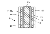
- FIG. 2C is a cross-sectional view of the distal end of the movable catheter of FIG. 2B cut along a plane passing through the respective axes of the pair of wire lumens.
- FIG. 3 is an enlarged view showing the distal end portion of the movable catheter of FIG. 1, and is a diagram for explaining the operation of the deflection portion.
- FIG. 1 is a diagram showing an external configuration of a movable catheter according to an embodiment of the present invention.
- FIG. 2A is a cross-sectional view taken along the line IIa-IIa of FIG.
- FIG. 2B is an enlarged perspective view showing a main part of the movable catheter of
- FIG. 4A is a perspective view showing a case where the number of wires inserted into the wire lumen of the movable catheter of FIG. 2B is increased.
- FIG. 4B is a cross-sectional view of the distal end of the movable catheter of FIG. 4A cut along a plane orthogonal to its axis.
- FIG. 4C is a cross-sectional view of the distal end of the movable catheter of FIG. 4A cut along a plane passing through the respective axes of the pair of wire lumens.
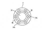
- FIG. 5A is a diagram showing a modified example of the movable catheter of FIG. 4A.
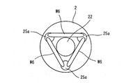
- FIG. 5B is a diagram showing another modification of the movable catheter of FIG. 4A.
- FIG. 5C is a diagram showing still another modification of the movable catheter of FIG. 4A.
- the catheter sheath as the movable catheter of the present embodiment precedes, for example, an electrode catheter for detecting electrocardiogram, an ablation catheter for cauterizing the affected area, and the like when performing catheter ablation. It is a catheter that is inserted and guides these electrode catheters, ablation catheters, and the like.
- a catheter sheath will be described as an example of a movable catheter to which the present invention is applied, but it is used for an electrode catheter, an ablation catheter, an X-ray contrast agent for injecting an X-ray contrast medium for examination in the bile duct, and the like.
- the present invention can also be applied to a movable endoscope catheter and other movable catheters.
- Catheter ablation is a treatment method for treating arrhythmia that occurs in the heart, and an ablation catheter having a high-frequency electrode at its tip is passed through a blood vessel to the myocardial tissue that causes the arrhythmia in the heart. It is a treatment method in which the myocardial tissue or its vicinity is inserted and cauterized at about 60 to 70 ° C. to cause coagulation necrosis and block the circuit of arrhythmia.
- the catheter sheath (movable catheter) 1 is configured to roughly include a sheath (tube) 2, an operating portion 3, a grip portion 4, and a pair of wires (operating means) W1 and W2.
- the sheath 2 is composed of a flexible hollow tube having a distal end inserted into the body and a proximal end arranged outside the body, and the sheath body portion (first tube portion) 20 arranged on the proximal end side. It is composed of a deflection portion (second tube portion) 21 arranged on the distal end side.
- the sheath body 20 is configured to have relatively high rigidity so that the flexibility does not substantially change even if a compressive force is applied in the direction along the axis (axis direction).
- a multilayer tube including a blade layer made of net-like stainless steel or the like and a plurality of resin layers is used as the sheath main body 20 .
- the deflection portion 21 is integrally joined so that the proximal end is continuous with the distal end of the sheath body portion 20.
- the lumen of the deflection portion 21 and the lumen of the sheath body portion 20 are continuously connected to each other, and the main lumen 22 is formed by these.
- the deflection portion 21 is composed of a porous tube that is compressed and hardened according to the degree of compressive force acting in the axial direction, and returns to its original state and becomes soft when the compressive force is released.
- the flexibility of the porous tube can be controlled by adjusting the compressive force acting in the axial direction.
- the material of the sheath body 20 is not particularly limited as long as it has flexibility, but is preferably a thermoplastic resin or a thermoplastic elastomer, for example, a polyamide-based elastomer such as a polyether blockamide copolymer.
- a polyamide-based elastomer such as a polyether blockamide copolymer.
- An alkyl vinyl ether copolymer or the like is used.
- the material of the porous tube constituting the deflection portion 21 is not limited, but the use of PTFE (polytetrafluoroethylene) is excellent in heat resistance, chemical resistance, weather resistance, water repellency, etc. Is preferable.
- PTFE polytetrafluoroethylene
- As the porous tube a tube produced by extruding PTFE and stretching the tube in the axial direction can be used. By making PTFE porous, it is possible to obtain the required waterproofness while maintaining air permeability. Further, the porosity can be adjusted by appropriately adjusting the stretching ratio (degree of stretching) during the stretching process, and the change in flexibility during compression can be appropriately adjusted (controlled). Is. It is also possible to change the ventilation performance by adjusting the porosity.
- the operation portion 3 and the grip portion 4 attached to the proximal end side of the sheath 2 are formed with an insertion hole through which the portion on the proximal end side of the sheath 2 is inserted, and the proximal end of the grip portion 4 is formed with an insertion hole. Is attached with a sheath hub 41a.
- the sheath hub 41a has a lumen, and the sheath 2 in the grip portion 4 is attached to the proximal end side of the sheath hub 41a so that the lumen of the sheath hub 41a and the main lumen 22 of the sheath 2 communicate with each other. There is. Further, a catheter insertion port provided with a hemostatic valve is formed on the distal end side of the sheath hub 41a.
- the catheter sheath 1 is used (during treatment)
- the above-mentioned electrode catheter or ablation catheter is inserted from the catheter insertion port of the sheath hub 41a and guided by the main lumen 22 of the sheath 2, and the respective distal ends are treated. It is guided to the myocardial tissue to be used.
- a side injection tube is formed on the side of the sheath hub 41a, and a three-way stopcock 41c is attached to the side injection tube via the tube 41b.
- a syringe or the like can be attached to the three-way stopcock 41c to suck blood in the body or send a drug solution into the body.
- a substantially cylindrical tip protection member 29 made of resin and having a hemispherical distal end side is provided.
- the tip protection member 29 has a lumen having substantially the same diameter as the main lumen 22 of the sheath 2, and is integrally joined (fixed) to the distal end of the sheath 2 (deflection portion 21) by heat fusion or the like. There is. However, the tip protection member 29 may be omitted.
- wire lumens (sub-lumens) 23a to 23d substantially parallel to the main lumen 22 are formed in the pipe wall of the sheath 2 (sheath body portion 20 and deflection portion 21) so as to surround the outside of the main lumen 22.
- the wire lumens 23a to 23d are formed from the proximal end of the sheath 2 (the proximal end of the sheath body 20) to the distal end (the distal end of the deflection portion 21).
- the wire lumens 23a to 23d are formed on the outside of the main lumen 22 with the axis of the sheath 2 as the center and separated from each other at an angular pitch (angle interval) of approximately 90 °.
- a single wire W1 is inserted through the wire lumen 23a and the wire lumen 23b, and a single wire W2 is inserted through the wire lumen 23c and the wire lumen 23d.
- the wires W1 and W2 are formed of a metal such as stainless steel, but the wires W1 and W2 may be formed of another material such as resin.
- Both ends of the wire W1 and both ends of the wire W2 are pulled out from the side holes provided in the sheath 2 inside the operation portion 3 provided on the proximal end side of the sheath 2, and the operation portion 3 (rotation operation member). It is connected to 31) respectively.
- the operation unit 3 has a pair of protruding grip portions 32, 32 integrally provided on the rotation operation member 31, and a holding portion 42 provided on the tip end (distal end) side of the grip portion 4. It is held via a screw-in type knob member 5.
- the rotation operating member 31 is indicated by a dashed-dotted line with reference numeral 31'in the figure by pressing both of the pair of grip portions 32, 32 toward the proximal end side.
- the holding portion 42 is held so as to be slid to the proximal end side by a predetermined amount.
- the rotation operation member 31 is urged by an urging means (not shown) so as to return to the original position when the pressing in the arrow A5 direction is released.
- both the wire W1 and the wire W2 are in a substantially untensioned state, and the deflection portion 21 at the tip of the sheath 2 is linear as shown in FIGS. 1 and 3 (a). It will be in an extended state. At this time, since no compressive force acts on the deflection portion 21 in the axial direction, the deflection portion 21 is not compressed and the dimension of the deflection portion 21 in the axial direction is L1 to form the deflection portion 21. Due to the nature of the porous tube, the deflection portion 21 is in a relatively soft state.
- the rotation operation member 31 When it is desired to fix the shape of the deflection portion 21 in a state where the deflection portion 21 is deflected, the rotation operation member 31 is pressed against the holding portion 42 by rotating the knob member 5 clockwise and tightening the knob member 5.
- the rotation operation member 31 is fixed at the current position, and the shape of the deflection portion 21 is fixed.
- the rotation operation member 31 When it is desired to release the fixed shape of the deflection portion 21 (when it is desired to adjust the deflection state), the rotation operation member 31 is held by the holding portion 42 by rotating the knob member 5 counterclockwise to loosen it, contrary to the above. It is in a state of being loosely pressed, and a state in which the rotation operation member 31 can rotate. As a result, the shape of the deflection portion 21 is not fixed, and the deflection state of the deflection portion 21 can be adjusted by gripping the grip portion 32 and rotating the rotation operation member 31.
- the proximal end of the deflection portion 21 is substantially restrained by the distal end of the sheath body portion 20 (does not move to the proximal end side), the force pulling the wires W1 and W2 toward the proximal end side causes , A compressive force acts on the deflection portion 21 in the axial direction. Due to this compressive force, the deflection portion 21 is compressed (shortened) in the direction along the axial center, and as shown in FIG. 3C, the dimension of the deflection portion 21 in the axial direction becomes L2, which is smaller than L1.
- the deflection portion 21 is in a relatively rigid state according to the properties of the porous tube constituting the portion 21.
- the rotation operating member 31 slides to the original position (neutral position) on the distal end side by the urging force of the urging means (not shown), and is relatively soft. It can be returned to the state. If it is desired to maintain the deflecting portion 21 in a relatively hard state, the knob member 5 is rotated clockwise and tightened, so that the rotation operating member 31 is pressed against the holding portion 42 and rotates. The operating member 31 is fixed at the current position. When it is desired to release this (when it is desired to make it soft or to adjust the deflection state), the rotation operation member 31 is held by rotating the knob member 5 counterclockwise to loosen it, contrary to the above. The rotation operating member 31 can be returned to the original position (neutral position) in a state of being loosely pressed by the 42.
- the rotation operation member 31 is slid toward the proximal end side to make the deflection portion 21 rigid, and then the rotation operation member 31 is rotated, as shown in FIG. 3 (d). It is also possible to deflect it in the compressed state. Further, by rotating the rotation operating member 31 in the neutral position (that is, the deflecting portion 21 is in a soft state) to appropriately deflect the deflecting portion 21, and then sliding the rotation operating member 31 toward the proximal end side, As shown in FIG. 3D, it can be compressed to be hard. Further, if necessary, when the rotation operation member 31 is slid from the neutral position to the proximal end side, the flexibility of the deflection portion 21 can be changed and controlled by appropriately adjusting the slide amount.
- the sheath 2 is continuous with the sheath main body 20 whose flexibility does not substantially change even when a compressive force is applied in the axial direction and the distal end of the sheath main body 20.
- 21 is made of a porous tube that is joined in such a manner and is compressed according to the degree of compressive force acting in the axial direction to become hard, and then returns to the original state to become soft when the compressive force is released. It is composed of and.
- the wires W1 and W2 inserted through the plurality of wire lumens 23a to 23d of the sheath 2 act to release the compressive force for compressing the deflection portion 21 in the axial direction and the deflection force for deflecting the deflection portion 21. I am doing it.
- the wires W1 and W2 are set to the neutral state, and one of the wires W1 and W2 is pulled toward the proximal end side while maintaining the soft state without applying a compressive force to the deflection portion 21, thereby causing the deflection portion 21.
- the deflecting portion 21 is in a soft state, good operability can be realized.
- breaking through (penetrating) a narrowed portion in a lumen of the body such as a bile duct
- the pair of wires W1 and W2 act on both the deflection force for deflecting the deflection portion 21 and the compression force for compressing the deflection portion 21.
- a wire for applying a deflection force and a wire for applying a compression force may be provided, and the configuration can be simplified as compared with the case where each is realized by another means.
- each of them may be realized by different means, of course.
- the outer diameter is slightly smaller than the inner diameter of the main lumen 22 so as to be slidable in the lumen (main lumen 22) of the sheath 2 (sheath body portion 20 and deflection portion 21).
- the compression tube is inserted, the distal end of the compression tube is connected to the distal end of the deflection portion 21, and the compression tube is pulled toward the proximal end side with respect to the sheath 2, thereby deflecting.
- a compressive force may be applied to the portion 21.
- the function as the main lumen is borne by the lumen of the compression tube.
- the substantially half W1a on one end side of the wire W1 is inserted into the lumen 23a for wire
- the substantially half W1b on the other end side is inserted into the lumen 23b for wire
- the one end side of the wire W2 is inserted.
- Approximately half W2a is inserted through the wire lumen 23c
- approximately half W2b on the other end side is inserted through the wire lumen 23d. Since the wires W1 and W2 are each folded back at the distal end of the deflection portion 21, it is not necessary to provide a member for fixing the wire such as a tip or a pull ring, and the number of parts can be reduced.
- the man-hours for manufacturing the member can be reduced. Further, since it is not necessary to secure an area for providing a member for fixing the wire in the structure of the catheter sheath 1, the structural limitation of the catheter sheath 1 can be reduced, for example, the sheath 2 (main). It is possible to increase the opening area of the distal end (tip) of the lumen 22).
- both the substantially half W1a inserted through the wire lumen 23a of the wire W1 and the substantially half W1b inserted through the wire lumen 23b are pulled so that a deflection force for deflecting the deflection portion 21 is applied. ing. Therefore, the force can be applied to a relatively wide range in the circumferential direction of the sheath 2 according to the distance (angle distance) between the wire lumen 23a and the wire lumen 23b. The same applies to the wire W2.
- the force applied to the wire is smaller than that in which the deflection operation is performed by pulling a single wire inserted through a single lumen without folding back, so that there is a risk of wire breakage due to the deflection operation. It becomes smaller. Further, it is possible to reduce the blurring of the distal end portion when deflecting the deflection portion 21, and it is possible to realize stable deflection. For the same reason, it becomes possible to stably apply a compressive force to the deflection portion 21.
- each wire lumens 23a to 23d that is, four wires are provided, and the distal end of each wire is connected to the distal end of the deflection portion 21.
- the number of lumens for wires and the number of wires may be 3 or 5 or more, respectively.
- two wires a wire W1 inserted through the wire lumen 23a and the wire lumen 23b, and a wire W2 inserted through the wire lumen 23c and the wire lumen 23d, are used.
- the wire W3 and the wire W4 may be added to form a configuration in which four wires are used.
- the deflecting portion 21 can be deflected in an arbitrary direction by 360 ° by appropriately selecting a combination of two adjacent wires W1 to W4 and adjusting the balance of the pulling force of each. Then, the deflection portion 21 can be made hard by pulling all of the wires W1 to W4, or the wires W1 and W2 or the wires W3 and W4 evenly (with the same tensile force). In addition, in response to the addition of the wires W3 and W4, it is necessary to appropriately change the configuration of the operation unit 3, such as adding a rotation operation member similar to the rotation operation member 31 in the operation unit 3.
- FIGS. 4A to 4C a case where four wire lumens 23a to 23d are provided and four wires W1 to W4 are provided has been described.
- the number of wire lumens can be increased or decreased, and the number of wires can be increased or decreased accordingly.
- FIG. 5A six wire lumens 24a are provided at an angle pitch of 60 °, and six wires W5 are provided.
- the deflection portion 21 can be deflected in six directions, and the combination of two adjacent wires W5 is appropriately selected to adjust the balance of the pulling forces of each. By doing so, the deflection portion 21 can be deflected by 360 ° in any direction.
- three wire lumens 25a are provided at an angular pitch of 120 °, and three wires W6 are provided.
- the deflection portion 21 can be deflected in three directions, and the combination of two adjacent wires W6 is appropriately selected to adjust the balance of the pulling forces of each. By doing so, the deflection portion 21 can be deflected by 360 ° in any direction.
- 24 wire lumens 26a are provided at an angle pitch of 15 °, and 24 wires W7 are provided. As a result, the deflection portion 21 can be deflected in 24 directions when the wires W7 are pulled one by one.
- the number of lumens for wires may be 3 or more, and the number of wires may be 2 or more.
- the number of wire lumens and the number of wires are the same, but they may be different, for example, with fewer wires than the number of wire lumens. May be good.
- both ends of the wire are inserted through a pair of adjacent wire lumens. For example, a pair of wire lumens are intermittently selected, and the wires are connected to these lumens. Both ends may be inserted.
- Catheter sheath (movable catheter) 2 ... Sheath (tube) 20 ... Sheath body (first tube) 21 ... Deflection part (second tube part) 22 ... Main lumen 23a to 23d ... Lumen for wire 29 ... Tip protection member 3 ... Operation part 31 ... Rotation operation member 32 ... Grip part 4 ; Grip part 42 ... Holding part 5 ... Knob member W1 to W7 ... Wire (operating means)
Landscapes
- Health & Medical Sciences (AREA)
- Life Sciences & Earth Sciences (AREA)
- Engineering & Computer Science (AREA)
- Biomedical Technology (AREA)
- Pulmonology (AREA)
- Anesthesiology (AREA)
- Biophysics (AREA)
- Heart & Thoracic Surgery (AREA)
- Hematology (AREA)
- Animal Behavior & Ethology (AREA)
- General Health & Medical Sciences (AREA)
- Public Health (AREA)
- Veterinary Medicine (AREA)
- Mechanical Engineering (AREA)
- Media Introduction/Drainage Providing Device (AREA)
Priority Applications (8)
| Application Number | Priority Date | Filing Date | Title |
|---|---|---|---|
| EP24171078.9A EP4378515B1 (en) | 2019-03-22 | 2020-03-02 | Steerable catheter |
| CN202080016125.7A CN113543832B (zh) | 2019-03-22 | 2020-03-02 | 活动式导管 |
| EP20779139.3A EP3943139B1 (en) | 2019-03-22 | 2020-03-02 | Steerable catheter |
| CN202310978521.3A CN116785567A (zh) | 2019-03-22 | 2020-03-02 | 活动式导管 |
| US17/593,619 US20220152357A1 (en) | 2019-03-22 | 2020-03-02 | Steerable catheter |
| KR1020217029649A KR20210143760A (ko) | 2019-03-22 | 2020-03-02 | 가동형 카테터 |
| JP2021508885A JP7523074B2 (ja) | 2019-03-22 | 2020-03-02 | 可動型カテーテル |
| JP2024108115A JP2024121015A (ja) | 2019-03-22 | 2024-07-04 | 可動型カテーテル |
Applications Claiming Priority (2)
| Application Number | Priority Date | Filing Date | Title |
|---|---|---|---|
| JP2019055397 | 2019-03-22 | ||
| JP2019-055397 | 2019-03-22 |
Publications (1)
| Publication Number | Publication Date |
|---|---|
| WO2020195582A1 true WO2020195582A1 (ja) | 2020-10-01 |
Family
ID=72608605
Family Applications (1)
| Application Number | Title | Priority Date | Filing Date |
|---|---|---|---|
| PCT/JP2020/008720 Ceased WO2020195582A1 (ja) | 2019-03-22 | 2020-03-02 | 可動型カテーテル |
Country Status (6)
| Country | Link |
|---|---|
| US (1) | US20220152357A1 (https=) |
| EP (2) | EP3943139B1 (https=) |
| JP (2) | JP7523074B2 (https=) |
| KR (1) | KR20210143760A (https=) |
| CN (2) | CN116785567A (https=) |
| WO (1) | WO2020195582A1 (https=) |
Cited By (2)
| Publication number | Priority date | Publication date | Assignee | Title |
|---|---|---|---|---|
| JP2021036171A (ja) * | 2019-08-23 | 2021-03-04 | 日星電気株式会社 | チューブ |
| WO2024203788A1 (ja) * | 2023-03-31 | 2024-10-03 | 日本ゼオン株式会社 | ステントデリバリー装置 |
Families Citing this family (3)
| Publication number | Priority date | Publication date | Assignee | Title |
|---|---|---|---|---|
| JP7293254B2 (ja) * | 2018-05-01 | 2023-06-19 | マゼラン・バイオメディカル インコーポレーテッド | 介入手術のための装置の操縦、追跡および誘導のためのシステムおよび方法 |
| US12551658B2 (en) | 2022-03-25 | 2026-02-17 | St. Jude Medical, Cardiology Division, Inc. | Steerable introducer with slide block divider |
| US20230364387A1 (en) * | 2022-05-11 | 2023-11-16 | Cephea Valve Technologies, Inc. | Advanced 3-Way Steering |
Citations (7)
| Publication number | Priority date | Publication date | Assignee | Title |
|---|---|---|---|---|
| JPH1033688A (ja) * | 1996-07-25 | 1998-02-10 | Olympus Optical Co Ltd | 可撓管 |
| JP2002272675A (ja) | 2001-03-16 | 2002-09-24 | Olympus Optical Co Ltd | カテーテル |
| JP2003525092A (ja) * | 2000-02-28 | 2003-08-26 | ボストン サイエンティフィック リミテッド | Ptfe部品を備えたバルーン構造 |
| JP2014514095A (ja) * | 2011-04-15 | 2014-06-19 | ダブリュ.エル.ゴア アンド アソシエイツ,インコーポレイティド | ピボットリングシール |
| JP2014188039A (ja) | 2013-03-26 | 2014-10-06 | Nippon Zeon Co Ltd | 先端可動カテーテル |
| JP2015530223A (ja) * | 2012-10-01 | 2015-10-15 | キューマックス,エルエルシー | 螺旋バルーンカテーテル |
| KR20180106612A (ko) * | 2017-03-21 | 2018-10-01 | 계명대학교 산학협력단 | 상하좌우 4방향의 4가지 유도선을 이용한, 말단 각도 조절 카테터 장치 및 이를 이용하는 방법 |
Family Cites Families (16)
| Publication number | Priority date | Publication date | Assignee | Title |
|---|---|---|---|---|
| US4280500A (en) * | 1978-03-31 | 1981-07-28 | Kazuaki Ono | Tubular flexible medical instrument |
| US4998916A (en) * | 1989-01-09 | 1991-03-12 | Hammerslag Julius G | Steerable medical device |
| JP3061461B2 (ja) * | 1991-10-25 | 2000-07-10 | オリンパス光学工業株式会社 | 管状挿入具 |
| US20050010095A1 (en) * | 1999-04-05 | 2005-01-13 | Medtronic, Inc. | Multi-purpose catheter apparatus and method of use |
| US7623899B2 (en) * | 2005-09-16 | 2009-11-24 | Biosense Webster, Inc. | Catheter with flexible pre-shaped tip section |
| US9254123B2 (en) | 2009-04-29 | 2016-02-09 | Hansen Medical, Inc. | Flexible and steerable elongate instruments with shape control and support elements |
| US9572953B2 (en) * | 2010-12-30 | 2017-02-21 | St. Jude Medical, Atrial Fibrillation Division, Inc. | Device having an electroformed pleated region and method of its manufacture |
| JP5557393B2 (ja) * | 2011-01-19 | 2014-07-23 | 日本ライフライン株式会社 | 先端偏向操作可能カテーテル |
| AU2012250729B2 (en) * | 2011-05-03 | 2016-12-01 | Shifamed Holdings, Llc | Steerable delivery sheaths |
| US9675781B2 (en) * | 2011-08-04 | 2017-06-13 | Kings College London | Continuum manipulator |
| US20160074627A1 (en) | 2014-09-15 | 2016-03-17 | Orbusneich Medical, Inc. | Vascular Re-entry Catheter |
| JP6265434B2 (ja) * | 2015-03-27 | 2018-01-24 | 日本ライフライン株式会社 | バルーン型アブレーションカテーテルおよびアブレーションカテーテル装置 |
| US10376673B2 (en) * | 2015-06-19 | 2019-08-13 | Evalve, Inc. | Catheter guiding system and methods |
| EP3181176A1 (en) * | 2015-12-14 | 2017-06-21 | Aeon Scientific AG | Magnetically guided medical device |
| SE1650363A1 (en) * | 2016-03-17 | 2017-09-18 | Madeleine Ramstedt | A catheter assembly |
| US11826524B2 (en) * | 2017-02-07 | 2023-11-28 | Qmax, Llc | Deflectable catheter with compound curve articulation and materials for the same |
-
2020
- 2020-03-02 KR KR1020217029649A patent/KR20210143760A/ko active Pending
- 2020-03-02 CN CN202310978521.3A patent/CN116785567A/zh active Pending
- 2020-03-02 JP JP2021508885A patent/JP7523074B2/ja active Active
- 2020-03-02 US US17/593,619 patent/US20220152357A1/en active Pending
- 2020-03-02 WO PCT/JP2020/008720 patent/WO2020195582A1/ja not_active Ceased
- 2020-03-02 EP EP20779139.3A patent/EP3943139B1/en active Active
- 2020-03-02 EP EP24171078.9A patent/EP4378515B1/en active Active
- 2020-03-02 CN CN202080016125.7A patent/CN113543832B/zh active Active
-
2024
- 2024-07-04 JP JP2024108115A patent/JP2024121015A/ja active Pending
Patent Citations (7)
| Publication number | Priority date | Publication date | Assignee | Title |
|---|---|---|---|---|
| JPH1033688A (ja) * | 1996-07-25 | 1998-02-10 | Olympus Optical Co Ltd | 可撓管 |
| JP2003525092A (ja) * | 2000-02-28 | 2003-08-26 | ボストン サイエンティフィック リミテッド | Ptfe部品を備えたバルーン構造 |
| JP2002272675A (ja) | 2001-03-16 | 2002-09-24 | Olympus Optical Co Ltd | カテーテル |
| JP2014514095A (ja) * | 2011-04-15 | 2014-06-19 | ダブリュ.エル.ゴア アンド アソシエイツ,インコーポレイティド | ピボットリングシール |
| JP2015530223A (ja) * | 2012-10-01 | 2015-10-15 | キューマックス,エルエルシー | 螺旋バルーンカテーテル |
| JP2014188039A (ja) | 2013-03-26 | 2014-10-06 | Nippon Zeon Co Ltd | 先端可動カテーテル |
| KR20180106612A (ko) * | 2017-03-21 | 2018-10-01 | 계명대학교 산학협력단 | 상하좌우 4방향의 4가지 유도선을 이용한, 말단 각도 조절 카테터 장치 및 이를 이용하는 방법 |
Non-Patent Citations (1)
| Title |
|---|
| See also references of EP3943139A4 |
Cited By (2)
| Publication number | Priority date | Publication date | Assignee | Title |
|---|---|---|---|---|
| JP2021036171A (ja) * | 2019-08-23 | 2021-03-04 | 日星電気株式会社 | チューブ |
| WO2024203788A1 (ja) * | 2023-03-31 | 2024-10-03 | 日本ゼオン株式会社 | ステントデリバリー装置 |
Also Published As
| Publication number | Publication date |
|---|---|
| EP4378515A3 (en) | 2024-08-14 |
| EP3943139A1 (en) | 2022-01-26 |
| EP3943139B1 (en) | 2024-05-08 |
| KR20210143760A (ko) | 2021-11-29 |
| JPWO2020195582A1 (https=) | 2020-10-01 |
| CN113543832A (zh) | 2021-10-22 |
| JP2024121015A (ja) | 2024-09-05 |
| US20220152357A1 (en) | 2022-05-19 |
| EP4378515A2 (en) | 2024-06-05 |
| CN116785567A (zh) | 2023-09-22 |
| EP3943139A4 (en) | 2022-12-28 |
| CN113543832B (zh) | 2023-08-22 |
| EP4378515B1 (en) | 2025-07-02 |
| JP7523074B2 (ja) | 2024-07-26 |
Similar Documents
| Publication | Publication Date | Title |
|---|---|---|
| WO2020195582A1 (ja) | 可動型カテーテル | |
| US10874415B2 (en) | Unitary endoscopic vessel harvesting devices | |
| JP7664578B2 (ja) | 可動型カテーテル | |
| CA2526381C (en) | Articulating mechanism for remote manipulation of a surgical or diagnostic tool | |
| JP5409655B2 (ja) | 操向可能チューブ | |
| JP2014516669A (ja) | 多方向性カテーテル制御ハンドル | |
| US20250375099A1 (en) | Braking mechanisms for steerable medical devices and related methods | |
| WO2015016139A1 (ja) | 腎動脈用ガイディングカテーテル及びその使用方法 | |
| WO2020195581A1 (ja) | 可動型カテーテル | |
| EP3310277B1 (en) | Unitary endoscopic vessel harvesting devices | |
| JP7663113B2 (ja) | 節輪構造体および可動型カテーテル | |
| JP2020124394A (ja) | 先端可動シース | |
| JP2018166953A (ja) | 医療用チューブ部品およびその製造方法 |
Legal Events
| Date | Code | Title | Description |
|---|---|---|---|
| 121 | Ep: the epo has been informed by wipo that ep was designated in this application |
Ref document number: 20779139 Country of ref document: EP Kind code of ref document: A1 |
|
| ENP | Entry into the national phase |
Ref document number: 2021508885 Country of ref document: JP Kind code of ref document: A |
|
| NENP | Non-entry into the national phase |
Ref country code: DE |
|
| WWE | Wipo information: entry into national phase |
Ref document number: 2020779139 Country of ref document: EP |