WO2020195582A1 - Steerable catheter - Google Patents
Steerable catheter Download PDFInfo
- Publication number
- WO2020195582A1 WO2020195582A1 PCT/JP2020/008720 JP2020008720W WO2020195582A1 WO 2020195582 A1 WO2020195582 A1 WO 2020195582A1 JP 2020008720 W JP2020008720 W JP 2020008720W WO 2020195582 A1 WO2020195582 A1 WO 2020195582A1
- Authority
- WO
- WIPO (PCT)
- Prior art keywords
- tube
- wire
- distal end
- catheter
- wires
- Prior art date
Links
- 230000008859 change Effects 0.000 claims abstract description 8
- 230000006835 compression Effects 0.000 abstract description 11
- 238000007906 compression Methods 0.000 abstract description 11
- 238000002679 ablation Methods 0.000 description 8
- 210000000013 bile duct Anatomy 0.000 description 8
- 230000007935 neutral effect Effects 0.000 description 8
- 238000011282 treatment Methods 0.000 description 8
- 238000003780 insertion Methods 0.000 description 6
- 230000037431 insertion Effects 0.000 description 6
- -1 polyethylene terephthalate Polymers 0.000 description 6
- 239000002872 contrast media Substances 0.000 description 5
- 238000010586 diagram Methods 0.000 description 5
- 238000005452 bending Methods 0.000 description 4
- 229920001343 polytetrafluoroethylene Polymers 0.000 description 4
- 239000004810 polytetrafluoroethylene Substances 0.000 description 4
- 230000006793 arrhythmia Effects 0.000 description 3
- 206010003119 arrhythmia Diseases 0.000 description 3
- 238000013153 catheter ablation Methods 0.000 description 3
- 229920001577 copolymer Polymers 0.000 description 3
- 238000002347 injection Methods 0.000 description 3
- 239000007924 injection Substances 0.000 description 3
- 239000000463 material Substances 0.000 description 3
- 238000000034 method Methods 0.000 description 3
- 230000002107 myocardial effect Effects 0.000 description 3
- 238000003825 pressing Methods 0.000 description 3
- 229920005989 resin Polymers 0.000 description 3
- 239000011347 resin Substances 0.000 description 3
- 210000004204 blood vessel Anatomy 0.000 description 2
- 230000003247 decreasing effect Effects 0.000 description 2
- 230000002183 duodenal effect Effects 0.000 description 2
- 230000004048 modification Effects 0.000 description 2
- 238000012986 modification Methods 0.000 description 2
- 230000000149 penetrating effect Effects 0.000 description 2
- 229920002647 polyamide Polymers 0.000 description 2
- 229910001220 stainless steel Inorganic materials 0.000 description 2
- 239000010935 stainless steel Substances 0.000 description 2
- 238000003466 welding Methods 0.000 description 2
- VGGSQFUCUMXWEO-UHFFFAOYSA-N Ethene Chemical compound C=C VGGSQFUCUMXWEO-UHFFFAOYSA-N 0.000 description 1
- 239000005977 Ethylene Substances 0.000 description 1
- 206010028851 Necrosis Diseases 0.000 description 1
- 208000031481 Pathologic Constriction Diseases 0.000 description 1
- 239000004952 Polyamide Substances 0.000 description 1
- 239000004962 Polyamide-imide Substances 0.000 description 1
- 229920002614 Polyether block amide Polymers 0.000 description 1
- 239000004698 Polyethylene Substances 0.000 description 1
- 239000004642 Polyimide Substances 0.000 description 1
- 239000004743 Polypropylene Substances 0.000 description 1
- 239000008280 blood Substances 0.000 description 1
- 210000004369 blood Anatomy 0.000 description 1
- 239000003814 drug Substances 0.000 description 1
- 229940079593 drug Drugs 0.000 description 1
- 210000001198 duodenum Anatomy 0.000 description 1
- 229920001971 elastomer Polymers 0.000 description 1
- 239000000806 elastomer Substances 0.000 description 1
- 230000004927 fusion Effects 0.000 description 1
- 230000002439 hemostatic effect Effects 0.000 description 1
- 238000004519 manufacturing process Methods 0.000 description 1
- 239000002184 metal Substances 0.000 description 1
- 210000000056 organ Anatomy 0.000 description 1
- 230000035699 permeability Effects 0.000 description 1
- 229920002312 polyamide-imide Polymers 0.000 description 1
- 229920000573 polyethylene Polymers 0.000 description 1
- 229920000139 polyethylene terephthalate Polymers 0.000 description 1
- 239000005020 polyethylene terephthalate Substances 0.000 description 1
- 229920001721 polyimide Polymers 0.000 description 1
- 229920001155 polypropylene Polymers 0.000 description 1
- 229920002635 polyurethane Polymers 0.000 description 1
- 239000004814 polyurethane Substances 0.000 description 1
- 229920000915 polyvinyl chloride Polymers 0.000 description 1
- 239000004800 polyvinyl chloride Substances 0.000 description 1
- 230000008569 process Effects 0.000 description 1
- 230000004044 response Effects 0.000 description 1
- 239000000243 solution Substances 0.000 description 1
- 230000036262 stenosis Effects 0.000 description 1
- 208000037804 stenosis Diseases 0.000 description 1
- 239000000126 substance Substances 0.000 description 1
- BFKJFAAPBSQJPD-UHFFFAOYSA-N tetrafluoroethene Chemical group FC(F)=C(F)F BFKJFAAPBSQJPD-UHFFFAOYSA-N 0.000 description 1
- 229920002725 thermoplastic elastomer Polymers 0.000 description 1
- 229920005992 thermoplastic resin Polymers 0.000 description 1
- 238000009423 ventilation Methods 0.000 description 1
- XLYOFNOQVPJJNP-UHFFFAOYSA-N water Substances O XLYOFNOQVPJJNP-UHFFFAOYSA-N 0.000 description 1
Images


Classifications
-
- A—HUMAN NECESSITIES
- A61—MEDICAL OR VETERINARY SCIENCE; HYGIENE
- A61M—DEVICES FOR INTRODUCING MEDIA INTO, OR ONTO, THE BODY; DEVICES FOR TRANSDUCING BODY MEDIA OR FOR TAKING MEDIA FROM THE BODY; DEVICES FOR PRODUCING OR ENDING SLEEP OR STUPOR
- A61M25/00—Catheters; Hollow probes
- A61M25/01—Introducing, guiding, advancing, emplacing or holding catheters
- A61M25/0105—Steering means as part of the catheter or advancing means; Markers for positioning
- A61M25/0133—Tip steering devices
- A61M25/0147—Tip steering devices with movable mechanical means, e.g. pull wires
-
- A—HUMAN NECESSITIES
- A61—MEDICAL OR VETERINARY SCIENCE; HYGIENE
- A61M—DEVICES FOR INTRODUCING MEDIA INTO, OR ONTO, THE BODY; DEVICES FOR TRANSDUCING BODY MEDIA OR FOR TAKING MEDIA FROM THE BODY; DEVICES FOR PRODUCING OR ENDING SLEEP OR STUPOR
- A61M25/00—Catheters; Hollow probes
- A61M25/0021—Catheters; Hollow probes characterised by the form of the tubing
- A61M25/0023—Catheters; Hollow probes characterised by the form of the tubing by the form of the lumen, e.g. cross-section, variable diameter
- A61M25/0026—Multi-lumen catheters with stationary elements
-
- A—HUMAN NECESSITIES
- A61—MEDICAL OR VETERINARY SCIENCE; HYGIENE
- A61M—DEVICES FOR INTRODUCING MEDIA INTO, OR ONTO, THE BODY; DEVICES FOR TRANSDUCING BODY MEDIA OR FOR TAKING MEDIA FROM THE BODY; DEVICES FOR PRODUCING OR ENDING SLEEP OR STUPOR
- A61M25/00—Catheters; Hollow probes
- A61M25/0067—Catheters; Hollow probes characterised by the distal end, e.g. tips
- A61M25/0074—Dynamic characteristics of the catheter tip, e.g. openable, closable, expandable or deformable
-
- A—HUMAN NECESSITIES
- A61—MEDICAL OR VETERINARY SCIENCE; HYGIENE
- A61M—DEVICES FOR INTRODUCING MEDIA INTO, OR ONTO, THE BODY; DEVICES FOR TRANSDUCING BODY MEDIA OR FOR TAKING MEDIA FROM THE BODY; DEVICES FOR PRODUCING OR ENDING SLEEP OR STUPOR
- A61M25/00—Catheters; Hollow probes
- A61M25/0067—Catheters; Hollow probes characterised by the distal end, e.g. tips
- A61M25/008—Strength or flexibility characteristics of the catheter tip
-
- A—HUMAN NECESSITIES
- A61—MEDICAL OR VETERINARY SCIENCE; HYGIENE
- A61M—DEVICES FOR INTRODUCING MEDIA INTO, OR ONTO, THE BODY; DEVICES FOR TRANSDUCING BODY MEDIA OR FOR TAKING MEDIA FROM THE BODY; DEVICES FOR PRODUCING OR ENDING SLEEP OR STUPOR
- A61M25/00—Catheters; Hollow probes
- A61M25/01—Introducing, guiding, advancing, emplacing or holding catheters
- A61M25/0105—Steering means as part of the catheter or advancing means; Markers for positioning
- A61M25/0133—Tip steering devices
- A61M25/0136—Handles therefor
-
- A—HUMAN NECESSITIES
- A61—MEDICAL OR VETERINARY SCIENCE; HYGIENE
- A61M—DEVICES FOR INTRODUCING MEDIA INTO, OR ONTO, THE BODY; DEVICES FOR TRANSDUCING BODY MEDIA OR FOR TAKING MEDIA FROM THE BODY; DEVICES FOR PRODUCING OR ENDING SLEEP OR STUPOR
- A61M25/00—Catheters; Hollow probes
- A61M25/01—Introducing, guiding, advancing, emplacing or holding catheters
- A61M25/0105—Steering means as part of the catheter or advancing means; Markers for positioning
- A61M25/0133—Tip steering devices
- A61M25/0147—Tip steering devices with movable mechanical means, e.g. pull wires
- A61M2025/015—Details of the distal fixation of the movable mechanical means
Definitions
- the present invention relates to a catheter, which is a medical treatment tool used for performing various treatments, examinations, etc., and particularly to a movable catheter (steerable catheter) capable of freely deflecting the tip portion and the like.
- medical treatment tools eg, contrast medium injection catheters, electrode catheters, ablation catheters, catheter sheaths
- target tissues such as various organs (eg, bile ducts, hearts) through body cavities, cavities, blood vessels, etc. )
- the tip (distal end) of the catheter inserted into the body is oriented to the base end (proximal end) of the catheter placed outside the body in order to facilitate its insertion and access to the target tissue.
- a movable catheter that can be deflected by operating an operation unit provided on the side is known (see, for example, Patent Document 1 and Patent Document 2).
- the catheter described in Patent Document 1 is a catheter for an endoscope used for injecting an X-ray contrast medium into the bile duct for examination in the bile duct, and extends to the duodenum via the endoscope. After being inserted, the tip is deflected (curved) by operating (pushing or pulling) the operation wire from outside the body so that the tip can be easily inserted into the duodenal papilla from the duodenal side to reach the inside of the bile duct. It is a catheter that can be used.
- the catheter described in Patent Document 1 has a lumen into which an operation wire for deflecting the tip portion is inserted, in addition to a large-diameter lumen used for injecting a contrast medium or the like. Since the wire is joined to the tip tip provided at the tip of the catheter by means such as plasma welding, the tip of the catheter can be deflected by pulling the operation wire on the outside of the body.
- the tip movable catheter described in Patent Document 2 is a catheter used for guiding an ablation catheter to a site to be treated in the heart in order to perform catheter ablation treatment on the heart, and the tip of the ablation catheter is the heart.
- This is a catheter in which the tip portion can be deflected (curved) by operating the operating portion from the outside of the body so that the catheter can be easily guided to a desired position.
- the catheter tube constituting the catheter described in Patent Document 2 has a pair of wire lumens at positions in the tube wall facing each other 180 ° in addition to the main lumen into which various treatment tools are inserted. are doing.
- the rigidity of the tip of the catheter tube to be deflected is set to be gradually lowered toward the tip, and the ring (pull ring) integrally attached to the tip is used for a wire.
- the tips of the pair of wires inserted into each of the lumens are connected by means such as laser welding, and the base ends of the pair of wires are connected to the operating portion. Then, by operating the operation unit, one wire is pulled and the other wire is loosened so that the direction of the tube tip can be controlled.
- the movable part (deflection part) needs to have flexibility enough to be easily and freely deflected (curved) by operating a wire.
- the configuration is flexible (soft) in consideration of operability, bending or buckling will occur when the stenosis in the lumen such as the bile duct is breached (penetrated), and the insertability is reduced.
- the configuration is rigid in consideration of operability, operability may be sacrificed.
- the present invention has been made in view of such an actual situation, and an object of the present invention is to provide a movable catheter capable of improving both operability and insertability in a compatible manner.
- the movable catheter according to the present invention is A mobile catheter with a flexible tube having a distal end inserted into the body and a proximal end located outside the body.
- the tube is joined to the first tube portion whose flexibility does not substantially change even when a compressive force is applied in the axial direction, and is continuously connected to the distal end of the first tube portion, and acts in the axial direction.
- It is provided with a second tube portion made of a porous tube that is compressed and hardened according to the degree of compressive force to be applied, and then returns to its original state and becomes soft when the compressive force is released. It has an operating means for exerting a compressive force for compressing the second tube portion in the axial direction and a deflection force for deflecting the second tube portion so as to be released.
- an operating means is appropriately operated to apply a deflection force to the second tube portion while maintaining a soft state without applying a compressive force to the second tube portion as much as possible.
- the second tube portion can be deflected, and at this time, since the second tube portion is in a soft state, good operability can be realized.
- the operating means is appropriately operated to apply a compressive force to the second tube portion to make it a rigid state. As a result, it is possible to suppress the occurrence of bending and buckling, and it is possible to improve the insertability. Therefore, it is possible to provide a movable catheter that can improve both operability and insertability in a compatible manner.
- the tube has at least three wire lumens arranged in the tube wall of the tube at a distance from each other from the proximal end to the distal end of the tube.
- the operating means about half of the one end side is inserted into one of the wire lumens, the middle part is folded back at the distal end of the second tube part, and about half of the other end side is provided.
- each end (one end and others) of all wires with the same tensile force between each wire so that a compressive force acts on the second tube.
- the second tube can be made rigid.
- the second tube portion is subjected to the difference in the tensile force. Can be deflected.
- the tube has at least three wire lumens arranged in the tube wall of the tube at a distance from each other from the proximal end to the distal end of the tube.
- the distal end is connected to the distal end of the second tube portion, inserted into one of the wire lumens, and the proximal end is the proximal end of the first tube portion. It is possible to have at least three wires leading to the above. By pulling each proximal end of all wires (or some appropriate wires depending on the placement of the wire lumen) with the same tensile force between each wire so that a compressive force acts on the second tube section. , The second tube portion can be made into a rigid state.
- the second tube portion is subjected to the difference in the tensile force. Can be deflected.
- FIG. 1 is a diagram showing an external configuration of a movable catheter according to an embodiment of the present invention.
- FIG. 2A is a cross-sectional view taken along the line IIa-IIa of FIG.
- FIG. 2B is an enlarged perspective view showing a main part of the movable catheter of FIG. 1.
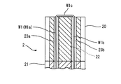
- FIG. 2C is a cross-sectional view of the distal end of the movable catheter of FIG. 2B cut along a plane passing through the respective axes of the pair of wire lumens.
- FIG. 3 is an enlarged view showing the distal end portion of the movable catheter of FIG. 1, and is a diagram for explaining the operation of the deflection portion.
- FIG. 1 is a diagram showing an external configuration of a movable catheter according to an embodiment of the present invention.
- FIG. 2A is a cross-sectional view taken along the line IIa-IIa of FIG.
- FIG. 2B is an enlarged perspective view showing a main part of the movable catheter of
- FIG. 4A is a perspective view showing a case where the number of wires inserted into the wire lumen of the movable catheter of FIG. 2B is increased.
- FIG. 4B is a cross-sectional view of the distal end of the movable catheter of FIG. 4A cut along a plane orthogonal to its axis.
- FIG. 4C is a cross-sectional view of the distal end of the movable catheter of FIG. 4A cut along a plane passing through the respective axes of the pair of wire lumens.
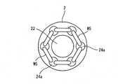
- FIG. 5A is a diagram showing a modified example of the movable catheter of FIG. 4A.
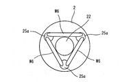
- FIG. 5B is a diagram showing another modification of the movable catheter of FIG. 4A.
- FIG. 5C is a diagram showing still another modification of the movable catheter of FIG. 4A.
- the catheter sheath as the movable catheter of the present embodiment precedes, for example, an electrode catheter for detecting electrocardiogram, an ablation catheter for cauterizing the affected area, and the like when performing catheter ablation. It is a catheter that is inserted and guides these electrode catheters, ablation catheters, and the like.
- a catheter sheath will be described as an example of a movable catheter to which the present invention is applied, but it is used for an electrode catheter, an ablation catheter, an X-ray contrast agent for injecting an X-ray contrast medium for examination in the bile duct, and the like.
- the present invention can also be applied to a movable endoscope catheter and other movable catheters.
- Catheter ablation is a treatment method for treating arrhythmia that occurs in the heart, and an ablation catheter having a high-frequency electrode at its tip is passed through a blood vessel to the myocardial tissue that causes the arrhythmia in the heart. It is a treatment method in which the myocardial tissue or its vicinity is inserted and cauterized at about 60 to 70 ° C. to cause coagulation necrosis and block the circuit of arrhythmia.
- the catheter sheath (movable catheter) 1 is configured to roughly include a sheath (tube) 2, an operating portion 3, a grip portion 4, and a pair of wires (operating means) W1 and W2.
- the sheath 2 is composed of a flexible hollow tube having a distal end inserted into the body and a proximal end arranged outside the body, and the sheath body portion (first tube portion) 20 arranged on the proximal end side. It is composed of a deflection portion (second tube portion) 21 arranged on the distal end side.
- the sheath body 20 is configured to have relatively high rigidity so that the flexibility does not substantially change even if a compressive force is applied in the direction along the axis (axis direction).
- a multilayer tube including a blade layer made of net-like stainless steel or the like and a plurality of resin layers is used as the sheath main body 20 .
- the deflection portion 21 is integrally joined so that the proximal end is continuous with the distal end of the sheath body portion 20.
- the lumen of the deflection portion 21 and the lumen of the sheath body portion 20 are continuously connected to each other, and the main lumen 22 is formed by these.
- the deflection portion 21 is composed of a porous tube that is compressed and hardened according to the degree of compressive force acting in the axial direction, and returns to its original state and becomes soft when the compressive force is released.
- the flexibility of the porous tube can be controlled by adjusting the compressive force acting in the axial direction.
- the material of the sheath body 20 is not particularly limited as long as it has flexibility, but is preferably a thermoplastic resin or a thermoplastic elastomer, for example, a polyamide-based elastomer such as a polyether blockamide copolymer.
- a polyamide-based elastomer such as a polyether blockamide copolymer.
- An alkyl vinyl ether copolymer or the like is used.
- the material of the porous tube constituting the deflection portion 21 is not limited, but the use of PTFE (polytetrafluoroethylene) is excellent in heat resistance, chemical resistance, weather resistance, water repellency, etc. Is preferable.
- PTFE polytetrafluoroethylene
- As the porous tube a tube produced by extruding PTFE and stretching the tube in the axial direction can be used. By making PTFE porous, it is possible to obtain the required waterproofness while maintaining air permeability. Further, the porosity can be adjusted by appropriately adjusting the stretching ratio (degree of stretching) during the stretching process, and the change in flexibility during compression can be appropriately adjusted (controlled). Is. It is also possible to change the ventilation performance by adjusting the porosity.
- the operation portion 3 and the grip portion 4 attached to the proximal end side of the sheath 2 are formed with an insertion hole through which the portion on the proximal end side of the sheath 2 is inserted, and the proximal end of the grip portion 4 is formed with an insertion hole. Is attached with a sheath hub 41a.
- the sheath hub 41a has a lumen, and the sheath 2 in the grip portion 4 is attached to the proximal end side of the sheath hub 41a so that the lumen of the sheath hub 41a and the main lumen 22 of the sheath 2 communicate with each other. There is. Further, a catheter insertion port provided with a hemostatic valve is formed on the distal end side of the sheath hub 41a.
- the catheter sheath 1 is used (during treatment)
- the above-mentioned electrode catheter or ablation catheter is inserted from the catheter insertion port of the sheath hub 41a and guided by the main lumen 22 of the sheath 2, and the respective distal ends are treated. It is guided to the myocardial tissue to be used.
- a side injection tube is formed on the side of the sheath hub 41a, and a three-way stopcock 41c is attached to the side injection tube via the tube 41b.
- a syringe or the like can be attached to the three-way stopcock 41c to suck blood in the body or send a drug solution into the body.
- a substantially cylindrical tip protection member 29 made of resin and having a hemispherical distal end side is provided.
- the tip protection member 29 has a lumen having substantially the same diameter as the main lumen 22 of the sheath 2, and is integrally joined (fixed) to the distal end of the sheath 2 (deflection portion 21) by heat fusion or the like. There is. However, the tip protection member 29 may be omitted.
- wire lumens (sub-lumens) 23a to 23d substantially parallel to the main lumen 22 are formed in the pipe wall of the sheath 2 (sheath body portion 20 and deflection portion 21) so as to surround the outside of the main lumen 22.
- the wire lumens 23a to 23d are formed from the proximal end of the sheath 2 (the proximal end of the sheath body 20) to the distal end (the distal end of the deflection portion 21).
- the wire lumens 23a to 23d are formed on the outside of the main lumen 22 with the axis of the sheath 2 as the center and separated from each other at an angular pitch (angle interval) of approximately 90 °.
- a single wire W1 is inserted through the wire lumen 23a and the wire lumen 23b, and a single wire W2 is inserted through the wire lumen 23c and the wire lumen 23d.
- the wires W1 and W2 are formed of a metal such as stainless steel, but the wires W1 and W2 may be formed of another material such as resin.
- Both ends of the wire W1 and both ends of the wire W2 are pulled out from the side holes provided in the sheath 2 inside the operation portion 3 provided on the proximal end side of the sheath 2, and the operation portion 3 (rotation operation member). It is connected to 31) respectively.
- the operation unit 3 has a pair of protruding grip portions 32, 32 integrally provided on the rotation operation member 31, and a holding portion 42 provided on the tip end (distal end) side of the grip portion 4. It is held via a screw-in type knob member 5.
- the rotation operating member 31 is indicated by a dashed-dotted line with reference numeral 31'in the figure by pressing both of the pair of grip portions 32, 32 toward the proximal end side.
- the holding portion 42 is held so as to be slid to the proximal end side by a predetermined amount.
- the rotation operation member 31 is urged by an urging means (not shown) so as to return to the original position when the pressing in the arrow A5 direction is released.
- both the wire W1 and the wire W2 are in a substantially untensioned state, and the deflection portion 21 at the tip of the sheath 2 is linear as shown in FIGS. 1 and 3 (a). It will be in an extended state. At this time, since no compressive force acts on the deflection portion 21 in the axial direction, the deflection portion 21 is not compressed and the dimension of the deflection portion 21 in the axial direction is L1 to form the deflection portion 21. Due to the nature of the porous tube, the deflection portion 21 is in a relatively soft state.
- the rotation operation member 31 When it is desired to fix the shape of the deflection portion 21 in a state where the deflection portion 21 is deflected, the rotation operation member 31 is pressed against the holding portion 42 by rotating the knob member 5 clockwise and tightening the knob member 5.
- the rotation operation member 31 is fixed at the current position, and the shape of the deflection portion 21 is fixed.
- the rotation operation member 31 When it is desired to release the fixed shape of the deflection portion 21 (when it is desired to adjust the deflection state), the rotation operation member 31 is held by the holding portion 42 by rotating the knob member 5 counterclockwise to loosen it, contrary to the above. It is in a state of being loosely pressed, and a state in which the rotation operation member 31 can rotate. As a result, the shape of the deflection portion 21 is not fixed, and the deflection state of the deflection portion 21 can be adjusted by gripping the grip portion 32 and rotating the rotation operation member 31.
- the proximal end of the deflection portion 21 is substantially restrained by the distal end of the sheath body portion 20 (does not move to the proximal end side), the force pulling the wires W1 and W2 toward the proximal end side causes , A compressive force acts on the deflection portion 21 in the axial direction. Due to this compressive force, the deflection portion 21 is compressed (shortened) in the direction along the axial center, and as shown in FIG. 3C, the dimension of the deflection portion 21 in the axial direction becomes L2, which is smaller than L1.
- the deflection portion 21 is in a relatively rigid state according to the properties of the porous tube constituting the portion 21.
- the rotation operating member 31 slides to the original position (neutral position) on the distal end side by the urging force of the urging means (not shown), and is relatively soft. It can be returned to the state. If it is desired to maintain the deflecting portion 21 in a relatively hard state, the knob member 5 is rotated clockwise and tightened, so that the rotation operating member 31 is pressed against the holding portion 42 and rotates. The operating member 31 is fixed at the current position. When it is desired to release this (when it is desired to make it soft or to adjust the deflection state), the rotation operation member 31 is held by rotating the knob member 5 counterclockwise to loosen it, contrary to the above. The rotation operating member 31 can be returned to the original position (neutral position) in a state of being loosely pressed by the 42.
- the rotation operation member 31 is slid toward the proximal end side to make the deflection portion 21 rigid, and then the rotation operation member 31 is rotated, as shown in FIG. 3 (d). It is also possible to deflect it in the compressed state. Further, by rotating the rotation operating member 31 in the neutral position (that is, the deflecting portion 21 is in a soft state) to appropriately deflect the deflecting portion 21, and then sliding the rotation operating member 31 toward the proximal end side, As shown in FIG. 3D, it can be compressed to be hard. Further, if necessary, when the rotation operation member 31 is slid from the neutral position to the proximal end side, the flexibility of the deflection portion 21 can be changed and controlled by appropriately adjusting the slide amount.
- the sheath 2 is continuous with the sheath main body 20 whose flexibility does not substantially change even when a compressive force is applied in the axial direction and the distal end of the sheath main body 20.
- 21 is made of a porous tube that is joined in such a manner and is compressed according to the degree of compressive force acting in the axial direction to become hard, and then returns to the original state to become soft when the compressive force is released. It is composed of and.
- the wires W1 and W2 inserted through the plurality of wire lumens 23a to 23d of the sheath 2 act to release the compressive force for compressing the deflection portion 21 in the axial direction and the deflection force for deflecting the deflection portion 21. I am doing it.
- the wires W1 and W2 are set to the neutral state, and one of the wires W1 and W2 is pulled toward the proximal end side while maintaining the soft state without applying a compressive force to the deflection portion 21, thereby causing the deflection portion 21.
- the deflecting portion 21 is in a soft state, good operability can be realized.
- breaking through (penetrating) a narrowed portion in a lumen of the body such as a bile duct
- the pair of wires W1 and W2 act on both the deflection force for deflecting the deflection portion 21 and the compression force for compressing the deflection portion 21.
- a wire for applying a deflection force and a wire for applying a compression force may be provided, and the configuration can be simplified as compared with the case where each is realized by another means.
- each of them may be realized by different means, of course.
- the outer diameter is slightly smaller than the inner diameter of the main lumen 22 so as to be slidable in the lumen (main lumen 22) of the sheath 2 (sheath body portion 20 and deflection portion 21).
- the compression tube is inserted, the distal end of the compression tube is connected to the distal end of the deflection portion 21, and the compression tube is pulled toward the proximal end side with respect to the sheath 2, thereby deflecting.
- a compressive force may be applied to the portion 21.
- the function as the main lumen is borne by the lumen of the compression tube.
- the substantially half W1a on one end side of the wire W1 is inserted into the lumen 23a for wire
- the substantially half W1b on the other end side is inserted into the lumen 23b for wire
- the one end side of the wire W2 is inserted.
- Approximately half W2a is inserted through the wire lumen 23c
- approximately half W2b on the other end side is inserted through the wire lumen 23d. Since the wires W1 and W2 are each folded back at the distal end of the deflection portion 21, it is not necessary to provide a member for fixing the wire such as a tip or a pull ring, and the number of parts can be reduced.
- the man-hours for manufacturing the member can be reduced. Further, since it is not necessary to secure an area for providing a member for fixing the wire in the structure of the catheter sheath 1, the structural limitation of the catheter sheath 1 can be reduced, for example, the sheath 2 (main). It is possible to increase the opening area of the distal end (tip) of the lumen 22).
- both the substantially half W1a inserted through the wire lumen 23a of the wire W1 and the substantially half W1b inserted through the wire lumen 23b are pulled so that a deflection force for deflecting the deflection portion 21 is applied. ing. Therefore, the force can be applied to a relatively wide range in the circumferential direction of the sheath 2 according to the distance (angle distance) between the wire lumen 23a and the wire lumen 23b. The same applies to the wire W2.
- the force applied to the wire is smaller than that in which the deflection operation is performed by pulling a single wire inserted through a single lumen without folding back, so that there is a risk of wire breakage due to the deflection operation. It becomes smaller. Further, it is possible to reduce the blurring of the distal end portion when deflecting the deflection portion 21, and it is possible to realize stable deflection. For the same reason, it becomes possible to stably apply a compressive force to the deflection portion 21.
- each wire lumens 23a to 23d that is, four wires are provided, and the distal end of each wire is connected to the distal end of the deflection portion 21.
- the number of lumens for wires and the number of wires may be 3 or 5 or more, respectively.
- two wires a wire W1 inserted through the wire lumen 23a and the wire lumen 23b, and a wire W2 inserted through the wire lumen 23c and the wire lumen 23d, are used.
- the wire W3 and the wire W4 may be added to form a configuration in which four wires are used.
- the deflecting portion 21 can be deflected in an arbitrary direction by 360 ° by appropriately selecting a combination of two adjacent wires W1 to W4 and adjusting the balance of the pulling force of each. Then, the deflection portion 21 can be made hard by pulling all of the wires W1 to W4, or the wires W1 and W2 or the wires W3 and W4 evenly (with the same tensile force). In addition, in response to the addition of the wires W3 and W4, it is necessary to appropriately change the configuration of the operation unit 3, such as adding a rotation operation member similar to the rotation operation member 31 in the operation unit 3.
- FIGS. 4A to 4C a case where four wire lumens 23a to 23d are provided and four wires W1 to W4 are provided has been described.
- the number of wire lumens can be increased or decreased, and the number of wires can be increased or decreased accordingly.
- FIG. 5A six wire lumens 24a are provided at an angle pitch of 60 °, and six wires W5 are provided.
- the deflection portion 21 can be deflected in six directions, and the combination of two adjacent wires W5 is appropriately selected to adjust the balance of the pulling forces of each. By doing so, the deflection portion 21 can be deflected by 360 ° in any direction.
- three wire lumens 25a are provided at an angular pitch of 120 °, and three wires W6 are provided.
- the deflection portion 21 can be deflected in three directions, and the combination of two adjacent wires W6 is appropriately selected to adjust the balance of the pulling forces of each. By doing so, the deflection portion 21 can be deflected by 360 ° in any direction.
- 24 wire lumens 26a are provided at an angle pitch of 15 °, and 24 wires W7 are provided. As a result, the deflection portion 21 can be deflected in 24 directions when the wires W7 are pulled one by one.
- the number of lumens for wires may be 3 or more, and the number of wires may be 2 or more.
- the number of wire lumens and the number of wires are the same, but they may be different, for example, with fewer wires than the number of wire lumens. May be good.
- both ends of the wire are inserted through a pair of adjacent wire lumens. For example, a pair of wire lumens are intermittently selected, and the wires are connected to these lumens. Both ends may be inserted.
- Catheter sheath (movable catheter) 2 ... Sheath (tube) 20 ... Sheath body (first tube) 21 ... Deflection part (second tube part) 22 ... Main lumen 23a to 23d ... Lumen for wire 29 ... Tip protection member 3 ... Operation part 31 ... Rotation operation member 32 ... Grip part 4 ; Grip part 42 ... Holding part 5 ... Knob member W1 to W7 ... Wire (operating means)
Landscapes
- Health & Medical Sciences (AREA)
- Life Sciences & Earth Sciences (AREA)
- Engineering & Computer Science (AREA)
- Anesthesiology (AREA)
- Biophysics (AREA)
- Pulmonology (AREA)
- Biomedical Technology (AREA)
- Heart & Thoracic Surgery (AREA)
- Hematology (AREA)
- Animal Behavior & Ethology (AREA)
- General Health & Medical Sciences (AREA)
- Public Health (AREA)
- Veterinary Medicine (AREA)
- Mechanical Engineering (AREA)
- Media Introduction/Drainage Providing Device (AREA)
Abstract
[Problem] To provide a steerable catheter with which both operability and insertability can be improved. [Solution] A steerable catheter comprises a flexible tube 2 having a distal end and a proximal end. The tube 2 comprises: a first tube section (sheath body section 20) the flexibility of which does not substantially change even upon receiving compression force in the axial direction; and a second tube section (deflection section 21) that is constituted by a porous tube which is joined so as to be continuous with a distal end of the first tube, and which becomes hard upon being compressed according to the degree of compression force acting in the axial direction and returns to being soft when the compression force is released. The tube includes an operation means (wires W1, W2) that releasably exerts a compression force which compresses the second tube section in the axial direction and a deflection force which deflects the second tube section.
Description
本発明は、各種の治療や検査等を行うために用いられる医療用処置具であるカテーテルに関し、特に、先端部等を自在に偏向することが可能な可動型カテーテル(Steerable Catheter)に関する。
The present invention relates to a catheter, which is a medical treatment tool used for performing various treatments, examinations, etc., and particularly to a movable catheter (steerable catheter) capable of freely deflecting the tip portion and the like.
体腔、管腔または血管等を通して、各種の臓器(たとえば、胆管、心臓)等の目的組織まで挿入される医療用処置具(たとえば、造影剤注入用カテーテル、電極カテーテル、アブレーションカテーテル、カテーテルシースを含む)として、その挿入や目的組織への接近の容易化等を図るため、体内に挿入されるカテーテルの先端(遠位端)の向きを、体外に配置されるカテーテルの基端(近位端)側に設けられた操作部を操作することにより偏向できるようにした可動型のカテーテルが知られている(たとえば、特許文献1および特許文献2参照)。
Includes medical treatment tools (eg, contrast medium injection catheters, electrode catheters, ablation catheters, catheter sheaths) that are inserted into target tissues such as various organs (eg, bile ducts, hearts) through body cavities, cavities, blood vessels, etc. ), The tip (distal end) of the catheter inserted into the body is oriented to the base end (proximal end) of the catheter placed outside the body in order to facilitate its insertion and access to the target tissue. A movable catheter that can be deflected by operating an operation unit provided on the side is known (see, for example, Patent Document 1 and Patent Document 2).
特許文献1に記載のカテーテルは、胆管内の検査のために胆管内にX線造影剤を注入するためなどに用いられる内視鏡用のカテーテルであって、内視鏡を介して十二指腸内まで挿入されたのち、先端部を十二指腸側から十二指腸乳頭に挿入して胆管内に到達させやすいように、体外側から操作ワイヤを操作する(押し出しまたは引っ張る)ことによって、先端部を偏向(湾曲)操作できるようにしたカテーテルである。この特許文献1に記載のカテーテルは、造影剤を注入するためなどに用いられる大径のルーメンとは別に、先端部を偏向操作するための操作ワイヤが挿入されるルーメンを有していて、操作ワイヤはカテーテルの先端部に設けられた先端チップとプラズマ溶接などの手段によって接合されているため、体外側の操作ワイヤを引っ張ることにより、カテーテルの先端部を偏向させることができる。
The catheter described in Patent Document 1 is a catheter for an endoscope used for injecting an X-ray contrast medium into the bile duct for examination in the bile duct, and extends to the duodenum via the endoscope. After being inserted, the tip is deflected (curved) by operating (pushing or pulling) the operation wire from outside the body so that the tip can be easily inserted into the duodenal papilla from the duodenal side to reach the inside of the bile duct. It is a catheter that can be used. The catheter described in Patent Document 1 has a lumen into which an operation wire for deflecting the tip portion is inserted, in addition to a large-diameter lumen used for injecting a contrast medium or the like. Since the wire is joined to the tip tip provided at the tip of the catheter by means such as plasma welding, the tip of the catheter can be deflected by pulling the operation wire on the outside of the body.
特許文献2に記載の先端可動カテーテルは、心臓に対してカテーテルアブレーション処置を行うためにアブレーションカテーテルを心臓の処置すべき部位まで案内するためなどに用いられるカテーテルであって、アブレーションカテーテルの先端を心臓の所望の位置に案内しやすいように、体外側から操作部を操作することによって、先端部を偏向(湾曲)操作できるようにしたカテーテルである。この特許文献2に記載されたカテーテルを構成するカテーテルチューブは、各種の処置具が挿入されるメインルーメンの他に、その管壁内の互いに180°対向する位置に、一対のワイヤ用ルーメンを有している。そして、カテーテルチューブの先端部の偏向すべき部分は、たとえば先端に行くにしたがってその剛性が段階的に低く設定されており、その先端部に一体的に装着されたリング(プルリング)に、ワイヤ用ルーメンのそれぞれに挿通された一対のワイヤのそれぞれの先端をレーザ溶接などの手段により接続し、該一対のワイヤのそれぞれの基端は操作部に接続してある。そして、その操作部を操作することによって、一方のワイヤを引っ張り、他方のワイヤを弛ませて、チューブ先端の向きを制御できるようにしている。
The tip movable catheter described in Patent Document 2 is a catheter used for guiding an ablation catheter to a site to be treated in the heart in order to perform catheter ablation treatment on the heart, and the tip of the ablation catheter is the heart. This is a catheter in which the tip portion can be deflected (curved) by operating the operating portion from the outside of the body so that the catheter can be easily guided to a desired position. The catheter tube constituting the catheter described in Patent Document 2 has a pair of wire lumens at positions in the tube wall facing each other 180 ° in addition to the main lumen into which various treatment tools are inserted. are doing. The rigidity of the tip of the catheter tube to be deflected is set to be gradually lowered toward the tip, and the ring (pull ring) integrally attached to the tip is used for a wire. The tips of the pair of wires inserted into each of the lumens are connected by means such as laser welding, and the base ends of the pair of wires are connected to the operating portion. Then, by operating the operation unit, one wire is pulled and the other wire is loosened so that the direction of the tube tip can be controlled.
ところで、この種の可動型カテーテルでは、可動部(偏向部)はワイヤの操作により容易かつ自在に偏向(湾曲)させ得る程度の柔軟性を有する必要がある。しかしながら、操作性を考慮して柔軟(軟質)な構成にすると、たとえば胆管等の管腔内の狭窄部を突破(貫通)させるような場合に屈曲や座屈が生じてしまい、挿入性が低下するおそれがある。反対に、操作性を考慮して剛直(硬質)な構成にすると、操作性が犠牲になるおそれがある。
By the way, in this type of movable catheter, the movable part (deflection part) needs to have flexibility enough to be easily and freely deflected (curved) by operating a wire. However, if the configuration is flexible (soft) in consideration of operability, bending or buckling will occur when the stenosis in the lumen such as the bile duct is breached (penetrated), and the insertability is reduced. There is a risk of On the contrary, if the configuration is rigid in consideration of operability, operability may be sacrificed.
本発明は、このような実状に鑑みてなされ、その目的は、操作性および挿入性を両立的に向上し得る可動型カテーテルを提供することである。
The present invention has been made in view of such an actual situation, and an object of the present invention is to provide a movable catheter capable of improving both operability and insertability in a compatible manner.
上記目的を達成するために、本発明に係る可動型カテーテルは、
体内に挿入される遠位端および体外に配置される近位端を備える可撓性のチューブを有する可動型カテーテルであって、
前記チューブは、軸心方向に圧縮力を受けても実質的に柔軟性が変化しない第1チューブ部と、該第1チューブ部の遠位端に連続するように接合され、軸心方向に作用する圧縮力の程度に応じて圧縮されて硬質となり、該圧縮力が解除されることにより元に戻って軟質となる多孔質チューブで構成された第2チューブ部とを備え、
前記第2チューブ部を軸心方向に圧縮する圧縮力および該第2チューブ部を偏向させる偏向力をそれぞれ解除可能に作用させる操作手段を有する。 In order to achieve the above object, the movable catheter according to the present invention is
A mobile catheter with a flexible tube having a distal end inserted into the body and a proximal end located outside the body.
The tube is joined to the first tube portion whose flexibility does not substantially change even when a compressive force is applied in the axial direction, and is continuously connected to the distal end of the first tube portion, and acts in the axial direction. It is provided with a second tube portion made of a porous tube that is compressed and hardened according to the degree of compressive force to be applied, and then returns to its original state and becomes soft when the compressive force is released.
It has an operating means for exerting a compressive force for compressing the second tube portion in the axial direction and a deflection force for deflecting the second tube portion so as to be released.
本発明に係る可動型カテーテルによれば、操作手段を適宜に操作して、第2チューブ部に圧縮力をなるべく作用させずに軟質な状態を維持したまま、第2チューブ部に偏向力を作用させることにより、第2チューブ部を偏向させることができ、このとき第2チューブ部は軟質な状態であるから、良好な操作性を実現することができる。一方、たとえば胆管等の体内管腔内の狭窄部を突破(貫通)させるような場合には、操作手段を適宜に操作して、第2チューブ部に圧縮力を作用させて硬質な状態とすることにより、屈曲や座屈が生じることを抑制することができ、挿入性を向上することができる。したがって、操作性および挿入性を両立的に向上し得る可動型カテーテルを提供することができる。
According to the movable catheter according to the present invention, an operating means is appropriately operated to apply a deflection force to the second tube portion while maintaining a soft state without applying a compressive force to the second tube portion as much as possible. By doing so, the second tube portion can be deflected, and at this time, since the second tube portion is in a soft state, good operability can be realized. On the other hand, in the case of breaking through (penetrating) a narrowed portion in the lumen of the body such as a bile duct, the operating means is appropriately operated to apply a compressive force to the second tube portion to make it a rigid state. As a result, it is possible to suppress the occurrence of bending and buckling, and it is possible to improve the insertability. Therefore, it is possible to provide a movable catheter that can improve both operability and insertability in a compatible manner.
本発明に係る可動型カテーテルにおいて、前記チューブは、該チューブの管壁内に、該チューブの近位端部から遠位端部に至る互いに離間して配置された少なくとも3本のワイヤ用ルーメンを備え、前記操作手段は、一端部側の略半分が前記ワイヤ用ルーメンの一つに挿通され、中間部分が前記第2チューブ部の遠位端部で折り返されて、他端部側の略半分が前記ワイヤ用ルーメンの他の一つに挿通され、一端部および他端部が前記第1チューブ部の近位端に至っている少なくとも2本のワイヤを備えることができる。第2チューブ部に圧縮力が作用するように各ワイヤ間で同じ引張力で全てのワイヤ(またはワイヤ用ルーメンの配置に応じた適宜な一部のワイヤ)のそれぞれの両端部(一端部および他端部)を引っ張ることにより、第2チューブ部を硬質な状態とさせ得る。また、第2チューブ部に偏向力が作用するように各ワイヤ間で引張力に差をつけて引っ張る(または一部のワイヤのみ引っ張る)ことにより、該引張力の差に応じて第2チューブ部を偏向させ得る。
In the movable catheter according to the present invention, the tube has at least three wire lumens arranged in the tube wall of the tube at a distance from each other from the proximal end to the distal end of the tube. In the operating means, about half of the one end side is inserted into one of the wire lumens, the middle part is folded back at the distal end of the second tube part, and about half of the other end side is provided. Can be provided with at least two wires that are inserted into the other one of the wire lumens, one end and the other end reaching the proximal end of the first tube. Each end (one end and others) of all wires (or some appropriate wires depending on the placement of the wire lumen) with the same tensile force between each wire so that a compressive force acts on the second tube. By pulling the end), the second tube can be made rigid. Further, by pulling (or pulling only a part of the wires) with a difference in tensile force between the wires so that a deflection force acts on the second tube portion, the second tube portion is subjected to the difference in the tensile force. Can be deflected.
本発明に係る可動型カテーテルにおいて、前記チューブは、該チューブの管壁内に、該チューブの近位端部から遠位端部に至る互いに離間して配置された少なくとも3本のワイヤ用ルーメンを備え、前記操作手段は、遠位端が前記第2チューブ部の遠位端部に接続され、前記ワイヤ用ルーメンの一つに挿通されて、近位端が前記第1チューブ部の近位端に至っている少なくとも3本のワイヤを備えることができる。第2チューブ部に圧縮力が作用するように各ワイヤ間で同じ引張力で全てのワイヤ(またはワイヤ用ルーメンの配置に応じた適宜な一部のワイヤ)のそれぞれの近位端を引っ張ることにより、第2チューブ部を硬質な状態とさせ得る。また、第2チューブ部に偏向力が作用するように各ワイヤ間で引張力に差をつけて引っ張る(または一部のワイヤのみ引っ張る)ことにより、該引張力の差に応じて第2チューブ部を偏向させ得る。
In the movable catheter according to the present invention, the tube has at least three wire lumens arranged in the tube wall of the tube at a distance from each other from the proximal end to the distal end of the tube. In the operating means, the distal end is connected to the distal end of the second tube portion, inserted into one of the wire lumens, and the proximal end is the proximal end of the first tube portion. It is possible to have at least three wires leading to the above. By pulling each proximal end of all wires (or some appropriate wires depending on the placement of the wire lumen) with the same tensile force between each wire so that a compressive force acts on the second tube section. , The second tube portion can be made into a rigid state. Further, by pulling (or pulling only a part of the wires) with a difference in tensile force between the wires so that a deflection force acts on the second tube portion, the second tube portion is subjected to the difference in the tensile force. Can be deflected.
以下、本発明の実施形態について、図面を参照して具体的に説明する。本実施形態の可動型カテーテルとしてのカテーテルシース(可動型シース)は、たとえば、カテーテルアブレーションを行う際に、心電を検出するための電極カテーテルや患部を焼灼するためのアブレーションカテーテル等に先行して挿入され、これらの電極カテーテルやアブレーションカテーテル等を案内するカテーテルである。以下では、本発明が適用される可動型カテーテルとして、カテーテルシースを例に説明するが、電極カテーテルやアブレーションカテーテル、胆管内の検査のために胆管内にX線造影剤を注入するためなどに用いられる可動型内視鏡用カテーテル、その他の可動型カテーテルにも本発明を適用することができる。
Hereinafter, embodiments of the present invention will be specifically described with reference to the drawings. The catheter sheath (movable sheath) as the movable catheter of the present embodiment precedes, for example, an electrode catheter for detecting electrocardiogram, an ablation catheter for cauterizing the affected area, and the like when performing catheter ablation. It is a catheter that is inserted and guides these electrode catheters, ablation catheters, and the like. In the following, a catheter sheath will be described as an example of a movable catheter to which the present invention is applied, but it is used for an electrode catheter, an ablation catheter, an X-ray contrast agent for injecting an X-ray contrast medium for examination in the bile duct, and the like. The present invention can also be applied to a movable endoscope catheter and other movable catheters.
なお、カテーテルアブレーションとは、心臓に生じる不整脈を治療するための治療法であり、その先端部に高周波電極を有するアブレーションカテーテルを血管を経由して心臓内の不整脈の原因となっている心筋組織まで挿入し、該心筋組織またはその近傍を60~70℃程度で焼灼して凝固壊死せしめ、不整脈の回路を遮断する治療法である。
Catheter ablation is a treatment method for treating arrhythmia that occurs in the heart, and an ablation catheter having a high-frequency electrode at its tip is passed through a blood vessel to the myocardial tissue that causes the arrhythmia in the heart. It is a treatment method in which the myocardial tissue or its vicinity is inserted and cauterized at about 60 to 70 ° C. to cause coagulation necrosis and block the circuit of arrhythmia.
まず、図1および図2A~図2Cを参照する。カテーテルシース(可動型カテーテル)1は、シース(チューブ)2、操作部3、グリップ部4、および一対のワイヤ(操作手段)W1,W2を概略備えて構成されている。
First, refer to FIGS. 1 and 2A to 2C. The catheter sheath (movable catheter) 1 is configured to roughly include a sheath (tube) 2, an operating portion 3, a grip portion 4, and a pair of wires (operating means) W1 and W2.
シース2は、体内に挿入される遠位端および体外に配置される近位端を有する可撓性の中空チューブからなり、近位端側に配置されるシース本体部(第1チューブ部)20および遠位端側に配置される偏向部(第2チューブ部)21から構成されている。シース本体部20は、軸心に沿う方向(軸心方向)に圧縮力を受けても実質的に柔軟性が変化しないように比較的に高い剛性を有するように構成されている。シース本体部20としては、たとえば網状のステンレス鋼等からなるブレード層および複数の樹脂層を含む多層チューブが用いられる。
The sheath 2 is composed of a flexible hollow tube having a distal end inserted into the body and a proximal end arranged outside the body, and the sheath body portion (first tube portion) 20 arranged on the proximal end side. It is composed of a deflection portion (second tube portion) 21 arranged on the distal end side. The sheath body 20 is configured to have relatively high rigidity so that the flexibility does not substantially change even if a compressive force is applied in the direction along the axis (axis direction). As the sheath main body 20, for example, a multilayer tube including a blade layer made of net-like stainless steel or the like and a plurality of resin layers is used.
偏向部21は、近位端がシース本体部20の遠位端に連続するように一体的に接合されている。偏向部21の内腔とシース本体部20の内腔とは、互いに連続して接続されており、これらによりメインルーメン22が構成されている。偏向部21は、軸心方向に作用する圧縮力の程度に応じて圧縮されて硬質となり、該圧縮力が解除されることにより元に戻って軟質となる多孔質チューブで構成されている。多孔質チューブは、軸心方向に作用させる圧縮力を調整することによって、その柔軟性を制御することができる。
The deflection portion 21 is integrally joined so that the proximal end is continuous with the distal end of the sheath body portion 20. The lumen of the deflection portion 21 and the lumen of the sheath body portion 20 are continuously connected to each other, and the main lumen 22 is formed by these. The deflection portion 21 is composed of a porous tube that is compressed and hardened according to the degree of compressive force acting in the axial direction, and returns to its original state and becomes soft when the compressive force is released. The flexibility of the porous tube can be controlled by adjusting the compressive force acting in the axial direction.
シース本体部20の材質は、可撓性を備えるものであれば特に限定されないが、熱可塑性樹脂または熱可塑性エラストマーであることが好ましく、たとえば、ポリエーテルブロックアミド共重合体などのポリアミド系エラストマー、ポリアミド、ポリイミド、ポリアミドイミド、ポリエチレンテレフタレート、ポリエチレン、ポリプロピレン、ポリウレタン、エチレン・酢酸ビニル共重合体、ポリ塩化ビニル、ポリテトラフルオロエチレン、テトラフルオロエチレン・ヘキサフルオロプロピレン共重合体、テトラフルオロエチレン・パーフルオロアルキルビニルエーテル共重合体などが用いられる。
The material of the sheath body 20 is not particularly limited as long as it has flexibility, but is preferably a thermoplastic resin or a thermoplastic elastomer, for example, a polyamide-based elastomer such as a polyether blockamide copolymer. Polyamide, polyimide, polyamideimide, polyethylene terephthalate, polyethylene, polypropylene, polyurethane, ethylene / vinyl acetate copolymer, polyvinyl chloride, polytetrafluoroethylene, tetrafluoroethylene / hexafluoropropylene copolymer, tetrafluoroethylene / perfluoro An alkyl vinyl ether copolymer or the like is used.
偏向部21を構成する多孔質チューブの材質としては、限定はされないが、PTFE(ポリテトラフルオロエチレン)を用いることが、耐熱性、耐薬品性、耐候性、撥水性等に優れていること等から好ましい。多孔質チューブとしては、PTFEを押し出し成形して得られたチューブを軸心方向に延伸加工することにより製造したものを用いることができる。PTFEを多孔質化することにより、通気性を保持しつつ必要な防水性を得ることができる。また、延伸加工する際の延伸率(延伸の度合い)を適宜に調整することにより、気孔率を調整することができ、圧縮した際の柔軟性の変化を適宜に調整(制御)することが可能である。なお、気孔率を調整することにより、通気性能を変化させることも可能である。
The material of the porous tube constituting the deflection portion 21 is not limited, but the use of PTFE (polytetrafluoroethylene) is excellent in heat resistance, chemical resistance, weather resistance, water repellency, etc. Is preferable. As the porous tube, a tube produced by extruding PTFE and stretching the tube in the axial direction can be used. By making PTFE porous, it is possible to obtain the required waterproofness while maintaining air permeability. Further, the porosity can be adjusted by appropriately adjusting the stretching ratio (degree of stretching) during the stretching process, and the change in flexibility during compression can be appropriately adjusted (controlled). Is. It is also possible to change the ventilation performance by adjusting the porosity.
シース2の近位端側に取り付けられた操作部3およびグリップ部4には、シース2の近位端側の部分が挿通される挿通孔が形成されていて、グリップ部4の近位端には、シースハブ41aが取り付けられている。
The operation portion 3 and the grip portion 4 attached to the proximal end side of the sheath 2 are formed with an insertion hole through which the portion on the proximal end side of the sheath 2 is inserted, and the proximal end of the grip portion 4 is formed with an insertion hole. Is attached with a sheath hub 41a.
シースハブ41aは内腔を有していて、シースハブ41aの近位端側にはグリップ部4内のシース2が、シースハブ41aの内腔とシース2のメインルーメン22とが連通するように取り付けられている。また、シースハブ41aの遠位端側には、止血弁を備えたカテーテル挿入口が形成されている。カテーテルシース1の使用時(処置時)には、上述した電極カテーテルやアブレーションカテーテルがシースハブ41aのカテーテル挿入口から挿入され、シース2のメインルーメン22に案内されて、それぞれの遠位端部が処置すべき心筋組織まで導かれる。また、シースハブ41aの側部には、側注管が形成されていて、その側注管にはチューブ41bを介して三方活栓41cが取り付けられている。三方活栓41cには、たとえばシリンジなどを取り付けて、体内の血液を吸引したり、体内に薬液を送り込んだりすることができる。
The sheath hub 41a has a lumen, and the sheath 2 in the grip portion 4 is attached to the proximal end side of the sheath hub 41a so that the lumen of the sheath hub 41a and the main lumen 22 of the sheath 2 communicate with each other. There is. Further, a catheter insertion port provided with a hemostatic valve is formed on the distal end side of the sheath hub 41a. When the catheter sheath 1 is used (during treatment), the above-mentioned electrode catheter or ablation catheter is inserted from the catheter insertion port of the sheath hub 41a and guided by the main lumen 22 of the sheath 2, and the respective distal ends are treated. It is guided to the myocardial tissue to be used. A side injection tube is formed on the side of the sheath hub 41a, and a three-way stopcock 41c is attached to the side injection tube via the tube 41b. For example, a syringe or the like can be attached to the three-way stopcock 41c to suck blood in the body or send a drug solution into the body.
シース2の遠位端(偏向部21の先端)には、樹脂からなり、遠位端側が半球状にされた略円筒状の先端保護部材29が設けられている。先端保護部材29は、シース2のメインルーメン22と略同径の内腔を有し、シース2(偏向部21)の遠位端部に熱融着等により一体的に接合(固着)されている。ただし、先端保護部材29は省略してもよい。
At the distal end of the sheath 2 (the tip of the deflection portion 21), a substantially cylindrical tip protection member 29 made of resin and having a hemispherical distal end side is provided. The tip protection member 29 has a lumen having substantially the same diameter as the main lumen 22 of the sheath 2, and is integrally joined (fixed) to the distal end of the sheath 2 (deflection portion 21) by heat fusion or the like. There is. However, the tip protection member 29 may be omitted.
シース2(シース本体部20および偏向部21)の管壁内には、メインルーメン22の外側を取り囲むように、メインルーメン22に略平行する4つのワイヤ用ルーメン(サブルーメン)23a~23dが形成されている。ワイヤ用ルーメン23a~23dは、シース2の近位端部(シース本体部20の近位端部)から遠位端部(偏向部21の遠位端部)に至って形成されている。ワイヤ用ルーメン23a~23dは、シース2の軸心を中心として、メインルーメン22の外側に、互いに略90°の角度ピッチ(角度間隔)で互いに離間して形成されている。
Four wire lumens (sub-lumens) 23a to 23d substantially parallel to the main lumen 22 are formed in the pipe wall of the sheath 2 (sheath body portion 20 and deflection portion 21) so as to surround the outside of the main lumen 22. Has been done. The wire lumens 23a to 23d are formed from the proximal end of the sheath 2 (the proximal end of the sheath body 20) to the distal end (the distal end of the deflection portion 21). The wire lumens 23a to 23d are formed on the outside of the main lumen 22 with the axis of the sheath 2 as the center and separated from each other at an angular pitch (angle interval) of approximately 90 °.
ワイヤ用ルーメン23aおよびワイヤ用ルーメン23bには、単一のワイヤW1が挿通されており、ワイヤ用ルーメン23cおよびワイヤ用ルーメン23dには、単一のワイヤW2が挿通されている。本実施形態では、ワイヤW1,W2は、ステンレス鋼等の金属から形成されているが、ワイヤW1,W2は、たとえば樹脂等の他の材料で形成されていてもよい。
A single wire W1 is inserted through the wire lumen 23a and the wire lumen 23b, and a single wire W2 is inserted through the wire lumen 23c and the wire lumen 23d. In the present embodiment, the wires W1 and W2 are formed of a metal such as stainless steel, but the wires W1 and W2 may be formed of another material such as resin.
ワイヤW1は、その一端部側の略半分W1aがワイヤ用ルーメン23aに挿通され、その中間部分W1cがシース2の先端保護部材29が接合される遠位端面で折り返されて、その他端部側の略半分W1bがワイヤ用ルーメン23bに挿通され、その両端部(一端部および他端部)がシース2の近位端側の操作部3に位置するように配置されている。同様に、ワイヤW2は、その一端部側の略半分W2aがワイヤ用ルーメン23cに挿通され、その中間部分W2cがシース2の先端保護部材29が接合される遠位端面で折り返されて、その他端部側の略半分W2bがワイヤ用ルーメン23dに挿通され、その両端部(一端部および他端部)がシース2の近位端側の操作部3に位置するように配置されている。
About half of the wire W1 on one end side is inserted into the lumen 23a for wire, and the intermediate portion W1c is folded back at the distal end surface to which the tip protection member 29 of the sheath 2 is joined, and the other end side. Approximately half W1b is inserted through the wire lumen 23b, and both ends (one end and the other end) thereof are arranged so as to be located at the operation portion 3 on the proximal end side of the sheath 2. Similarly, in the wire W2, approximately half W2a on one end side thereof is inserted into the lumen 23c for the wire, and the intermediate portion W2c thereof is folded back at the distal end surface to which the tip protection member 29 of the sheath 2 is joined, and the other end. Approximately half W2b on the portion side is inserted into the lumen 23d for wire, and both end portions (one end portion and the other end portion) thereof are arranged so as to be located at the operation portion 3 on the proximal end side of the sheath 2.
ワイヤW1の両端部ならびにワイヤW2の両端部は、シース2の近位端側に設けられた操作部3の内部においてシース2に設けられた側孔から引き出されて、操作部3(回転操作部材31)にそれぞれ接続されている。操作部3は、回転操作部材31に一体的に設けられた一対の突起状の把持部32,32を有しており、グリップ部4の先端(遠位端)側に設けられた保持部42にねじ込み式のノブ部材5を介して保持されている。
Both ends of the wire W1 and both ends of the wire W2 are pulled out from the side holes provided in the sheath 2 inside the operation portion 3 provided on the proximal end side of the sheath 2, and the operation portion 3 (rotation operation member). It is connected to 31) respectively. The operation unit 3 has a pair of protruding grip portions 32, 32 integrally provided on the rotation operation member 31, and a holding portion 42 provided on the tip end (distal end) side of the grip portion 4. It is held via a screw-in type knob member 5.
回転操作部材31は、図1に矢印A5で示すように、一対の把持部32,32の両方を近位端側に押圧することにより、同図に符号31’を付して一点鎖線で示すように、近位端側に所定量だけスライドできるように保持部42に保持されている。回転操作部材31は、矢印A5方向への押圧を解除すると、元の位置に戻るように、不図示の付勢手段により付勢されている。
As shown by the arrow A5 in FIG. 1, the rotation operating member 31 is indicated by a dashed-dotted line with reference numeral 31'in the figure by pressing both of the pair of grip portions 32, 32 toward the proximal end side. As described above, the holding portion 42 is held so as to be slid to the proximal end side by a predetermined amount. The rotation operation member 31 is urged by an urging means (not shown) so as to return to the original position when the pressing in the arrow A5 direction is released.
図1に示したニュートラル状態では、ワイヤW1およびワイヤW2が両者とも実質的に無張力状態となり、シース2の先端の偏向部21は、図1および図3(a)に示す通り、直線状に延びた状態となる。このとき、偏向部21には、軸心方向に圧縮力が作用していないので、圧縮されることなく、偏向部21の軸心方向の寸法はL1となっており、偏向部21を構成する多孔質チューブの性質により、偏向部21は比較的に軟質な状態となっている。
In the neutral state shown in FIG. 1, both the wire W1 and the wire W2 are in a substantially untensioned state, and the deflection portion 21 at the tip of the sheath 2 is linear as shown in FIGS. 1 and 3 (a). It will be in an extended state. At this time, since no compressive force acts on the deflection portion 21 in the axial direction, the deflection portion 21 is not compressed and the dimension of the deflection portion 21 in the axial direction is L1 to form the deflection portion 21. Due to the nature of the porous tube, the deflection portion 21 is in a relatively soft state.
ニュートラル状態から、回転操作部材31の把持部32,32を操作して、回転操作部材31を図1において矢印A1の方向に回転させると、この回転に伴い、ワイヤW1が引っ張られ、ワイヤW2が緩められることにより、先端の偏向部21が図1および図3(b)において矢印A3に示すように偏向される。
When the grip portions 32, 32 of the rotation operation member 31 are operated to rotate the rotation operation member 31 in the direction of the arrow A1 in FIG. 1 from the neutral state, the wire W1 is pulled and the wire W2 is pulled along with this rotation. By being loosened, the deflection portion 21 at the tip is deflected as shown by arrow A3 in FIGS. 1 and 3 (b).
これと反対に、回転操作部材31の把持部32,32を操作して、回転操作部材31を図1において矢印A2方向に回転させると、ワイヤW1が緩められ、ワイヤW2が引っ張られることにより、先端の偏向部21が図1および図3(b)において矢印A4に示すように偏向される。
On the contrary, when the grip portions 32, 32 of the rotation operation member 31 are operated to rotate the rotation operation member 31 in the direction of the arrow A2 in FIG. 1, the wire W1 is loosened and the wire W2 is pulled. The deflection portion 21 at the tip is deflected as shown by arrow A4 in FIGS. 1 and 3 (b).
偏向部21を偏向させた状態で、偏向部21の形状を固定したい場合には、ノブ部材5を時計方向に回転させて締め込むことにより、回転操作部材31が保持部42に押圧されて、回転操作部材31が現在位置で固定され、偏向部21の形状が固定される。偏向部21の形状の固定を解除したい場合(偏向状態を調整したい場合)には、上記と反対に、ノブ部材5を反時計方向に回転させて緩めることにより、回転操作部材31が保持部42に緩く押圧された状態となり、回転操作部材31が回転し得る状態となる。その結果、偏向部21の形状の固定が解除されて、把持部32を把持して回転操作部材31を回転操作することにより偏向部21の偏向状態を調整することができる。
When it is desired to fix the shape of the deflection portion 21 in a state where the deflection portion 21 is deflected, the rotation operation member 31 is pressed against the holding portion 42 by rotating the knob member 5 clockwise and tightening the knob member 5. The rotation operation member 31 is fixed at the current position, and the shape of the deflection portion 21 is fixed. When it is desired to release the fixed shape of the deflection portion 21 (when it is desired to adjust the deflection state), the rotation operation member 31 is held by the holding portion 42 by rotating the knob member 5 counterclockwise to loosen it, contrary to the above. It is in a state of being loosely pressed, and a state in which the rotation operation member 31 can rotate. As a result, the shape of the deflection portion 21 is not fixed, and the deflection state of the deflection portion 21 can be adjusted by gripping the grip portion 32 and rotating the rotation operation member 31.
次に、図1に示したニュートラル状態から、把持部32,32の両方を同図に矢印A5で示すように、不図示の付勢手段の付勢力に抗して近位端側に押圧すると、回転操作部材31が近位端側に所定量だけスライドする。この状態では、ワイヤW1,W2の両方が略均等に近位端側(同じ引張力で)に引っ張られて緊張し、その結果、偏向部21の遠位端に緊張したワイヤW1,W2による力が作用する。すなわち、偏向部21の近位端はシース本体部20の遠位端によって実質的に拘束されている(近位端側に移動しない)ため、ワイヤW1,W2による近位端側に引っ張る力により、偏向部21には軸心方向に圧縮力が作用する。この圧縮力により、偏向部21は軸心に沿う方向に圧縮(短縮)されて、図3(c)に示すように、偏向部21の軸心方向の寸法がL1よりも小さいL2となり、偏向部21を構成する多孔質チューブの性質にしたがって、偏向部21は比較的に硬質な状態となる。
Next, from the neutral state shown in FIG. 1, when both the grip portions 32 and 32 are pressed toward the proximal end side against the urging force of the urging means (not shown) as shown by the arrow A5 in the figure. , The rotation operating member 31 slides toward the proximal end side by a predetermined amount. In this state, both the wires W1 and W2 are pulled substantially evenly toward the proximal end side (with the same tensile force) and become tense, and as a result, the force due to the wires W1 and W2 tense at the distal end of the deflection portion 21. Works. That is, since the proximal end of the deflection portion 21 is substantially restrained by the distal end of the sheath body portion 20 (does not move to the proximal end side), the force pulling the wires W1 and W2 toward the proximal end side causes , A compressive force acts on the deflection portion 21 in the axial direction. Due to this compressive force, the deflection portion 21 is compressed (shortened) in the direction along the axial center, and as shown in FIG. 3C, the dimension of the deflection portion 21 in the axial direction becomes L2, which is smaller than L1. The deflection portion 21 is in a relatively rigid state according to the properties of the porous tube constituting the portion 21.
把持部32,32に対する押圧力を解除すれば、不図示の付勢手段の付勢力によって、回転操作部材31が遠位端側の元の位置(ニュートラル位置)にスライドし、比較的に軟質な状態に戻すことができる。偏向部21を比較的に硬質とした状態で、これを維持したい場合には、ノブ部材5を時計方向に回転させて締め込むことにより、回転操作部材31が保持部42に押圧されて、回転操作部材31が現在位置で固定される。これを解除したい場合(軟質な状態としたい、あるいは偏向状態を調整したい場合)には、上記と反対に、ノブ部材5を反時計方向に回転させて緩めることにより、回転操作部材31が保持部42に緩く押圧された状態となり、回転操作部材31が元の位置(ニュートラル位置)に戻すことができる。
When the pressing force on the grips 32 and 32 is released, the rotation operating member 31 slides to the original position (neutral position) on the distal end side by the urging force of the urging means (not shown), and is relatively soft. It can be returned to the state. If it is desired to maintain the deflecting portion 21 in a relatively hard state, the knob member 5 is rotated clockwise and tightened, so that the rotation operating member 31 is pressed against the holding portion 42 and rotates. The operating member 31 is fixed at the current position. When it is desired to release this (when it is desired to make it soft or to adjust the deflection state), the rotation operation member 31 is held by rotating the knob member 5 counterclockwise to loosen it, contrary to the above. The rotation operating member 31 can be returned to the original position (neutral position) in a state of being loosely pressed by the 42.
なお、必要があれば、回転操作部材31を近位端側にスライドさせて偏向部21を硬質にした状態で、回転操作部材31を回転させることにより、図3(d)に示すように、圧縮された状態で、偏向させることも可能である。また、ニュートラル位置(すなわち、偏向部21が軟質な状態)で回転操作部材31を回転させて偏向部21を適宜に偏向させた後に、回転操作部材31を近位端側にスライドさせることにより、図3(d)に示すように、圧縮して硬質とすることも可能である。また、必要があれば、回転操作部材31をニュートラル位置から近位端側にスライドさせる際に、そのスライド量を適宜調整することにより、偏向部21の柔軟性を変更制御することもできる。
If necessary, the rotation operation member 31 is slid toward the proximal end side to make the deflection portion 21 rigid, and then the rotation operation member 31 is rotated, as shown in FIG. 3 (d). It is also possible to deflect it in the compressed state. Further, by rotating the rotation operating member 31 in the neutral position (that is, the deflecting portion 21 is in a soft state) to appropriately deflect the deflecting portion 21, and then sliding the rotation operating member 31 toward the proximal end side, As shown in FIG. 3D, it can be compressed to be hard. Further, if necessary, when the rotation operation member 31 is slid from the neutral position to the proximal end side, the flexibility of the deflection portion 21 can be changed and controlled by appropriately adjusting the slide amount.
上述した実施形態では、偏向部21として、シース2を、軸心方向に圧縮力を受けても実質的に柔軟性が変化しないシース本体部20と、シース本体部20の遠位端に連続するように接合され、軸心方向に作用する圧縮力の程度に応じて圧縮されて硬質となり、該圧縮力が解除されることにより元に戻って軟質となる多孔質チューブで構成された偏向部21とから構成している。そして、シース2の複数のワイヤ用ルーメン23a~23dに挿通されたワイヤW1,W2により、偏向部21を軸心方向に圧縮する圧縮力および偏向部21を偏向させる偏向力を解除可能に作用させるようにしている。
In the above-described embodiment, as the deflection portion 21, the sheath 2 is continuous with the sheath main body 20 whose flexibility does not substantially change even when a compressive force is applied in the axial direction and the distal end of the sheath main body 20. 21 is made of a porous tube that is joined in such a manner and is compressed according to the degree of compressive force acting in the axial direction to become hard, and then returns to the original state to become soft when the compressive force is released. It is composed of and. Then, the wires W1 and W2 inserted through the plurality of wire lumens 23a to 23d of the sheath 2 act to release the compressive force for compressing the deflection portion 21 in the axial direction and the deflection force for deflecting the deflection portion 21. I am doing it.
これにより、ワイヤW1,W2をニュートラル状態として、偏向部21に圧縮力を作用させずに軟質な状態を維持したまま、ワイヤW1,W2の一方を近位端側に引っ張ることにより、偏向部21を偏向させることができ、このとき偏向部21は軟質な状態であるから、良好な操作性を実現することができる。一方、たとえば胆管等の体内管腔内の狭窄部を突破(貫通)させるような場合には、偏向部21が軟質な状態では、屈曲や座屈が生じて挿入が困難となる場合がある。この場合には、ワイヤW1,W2の両方を同じ引張力で近位端側に引っ張ることにより、偏向部21に圧縮力を作用させて硬質な状態とすることができる。このため、偏向部21に屈曲や座屈が生じることを少なくでき、カテーテルの挿入性を向上することができる。
As a result, the wires W1 and W2 are set to the neutral state, and one of the wires W1 and W2 is pulled toward the proximal end side while maintaining the soft state without applying a compressive force to the deflection portion 21, thereby causing the deflection portion 21. At this time, since the deflecting portion 21 is in a soft state, good operability can be realized. On the other hand, for example, in the case of breaking through (penetrating) a narrowed portion in a lumen of the body such as a bile duct, if the deflecting portion 21 is in a soft state, bending or buckling may occur and insertion may be difficult. In this case, by pulling both the wires W1 and W2 toward the proximal end side with the same tensile force, a compressive force can be applied to the deflection portion 21 to make the wires W1 and W2 into a rigid state. Therefore, it is possible to reduce the occurrence of bending or buckling in the deflection portion 21, and it is possible to improve the insertability of the catheter.
また、上述した実施形態では、一対のワイヤW1,W2により、偏向部21を偏向させるための偏向力と、偏向部21を圧縮させるための圧縮力との両方を作用させるようにしているため、たとえば、偏向力を作用させるためのワイヤと、圧縮力を作用させるためのワイヤとを設ける等、それぞれを別の手段で実現する場合と比較して、構成を簡略にし得る。ただし、それぞれを別の手段で実現しても勿論よい。たとえば、圧縮力を作用させるための手段として、シース2(シース本体部20および偏向部21)の内腔(メインルーメン22)に摺動可能に、メインルーメン22の内径よりも僅かに小さい外径を有する圧縮用チューブを挿通し、該圧縮用チューブの遠位端を偏向部21の遠位端に接続して、シース2に対して、圧縮用チューブを近位端側に引っ張ることにより、偏向部21に圧縮力を作用させるようにしてもよい。なお、この場合、メインルーメンとしての機能は、圧縮用チューブの内腔が担うことになる。
Further, in the above-described embodiment, the pair of wires W1 and W2 act on both the deflection force for deflecting the deflection portion 21 and the compression force for compressing the deflection portion 21. For example, a wire for applying a deflection force and a wire for applying a compression force may be provided, and the configuration can be simplified as compared with the case where each is realized by another means. However, each of them may be realized by different means, of course. For example, as a means for applying a compressive force, the outer diameter is slightly smaller than the inner diameter of the main lumen 22 so as to be slidable in the lumen (main lumen 22) of the sheath 2 (sheath body portion 20 and deflection portion 21). The compression tube is inserted, the distal end of the compression tube is connected to the distal end of the deflection portion 21, and the compression tube is pulled toward the proximal end side with respect to the sheath 2, thereby deflecting. A compressive force may be applied to the portion 21. In this case, the function as the main lumen is borne by the lumen of the compression tube.
さらに、上述した実施形態では、ワイヤW1の一端部側の略半分W1aをワイヤ用ルーメン23aに挿通し、他端側の略半分W1bをワイヤ用ルーメン23bに挿通し、ワイヤW2の一端部側の略半分W2aをワイヤ用ルーメン23cに挿通し、他端側の略半分W2bをワイヤ用ルーメン23dに挿通している。ワイヤW1,W2は、それぞれ偏向部21の遠位端部で折り返されているため、先端チップやプルリングのようなワイヤを固定するための部材を設ける必要がなく、部品点数を削減することができるとともに、ワイヤを固定するための部材のカテーテルチューブに対する装着作業やその部材に対するワイヤの接続作業を行う必要がないので、その製造における作業工数を削減することができる。また、ワイヤを固定するための部材を設けるための領域をカテーテルシース1の構造内に確保する必要がないので、カテーテルシース1としての構造上の制限を少なくすることができ、たとえばシース2(メインルーメン22)の遠位端(先端)の開口面積を大きくすることが可能となる。
Further, in the above-described embodiment, the substantially half W1a on one end side of the wire W1 is inserted into the lumen 23a for wire, the substantially half W1b on the other end side is inserted into the lumen 23b for wire, and the one end side of the wire W2 is inserted. Approximately half W2a is inserted through the wire lumen 23c, and approximately half W2b on the other end side is inserted through the wire lumen 23d. Since the wires W1 and W2 are each folded back at the distal end of the deflection portion 21, it is not necessary to provide a member for fixing the wire such as a tip or a pull ring, and the number of parts can be reduced. At the same time, since it is not necessary to attach the member for fixing the wire to the catheter tube and to connect the wire to the member, the man-hours for manufacturing the member can be reduced. Further, since it is not necessary to secure an area for providing a member for fixing the wire in the structure of the catheter sheath 1, the structural limitation of the catheter sheath 1 can be reduced, for example, the sheath 2 (main). It is possible to increase the opening area of the distal end (tip) of the lumen 22).
また、ワイヤW1のワイヤ用ルーメン23aに挿通された略半分W1aとワイヤ用ルーメン23bに挿通された略半分W1bとの両方を引っ張って、偏向部21を偏向するための偏向力を作用させるようにしている。このため、ワイヤ用ルーメン23aとワイヤ用ルーメン23bとの間隔(角度間隔)に応じて、シース2の周方向における比較的に広い範囲に力を作用させることができる。ワイヤW2に関しても同様である。その結果、単一のルーメンに挿通された折り返しのない1本のワイヤを引っ張ることにより偏向操作を行うものと比較して、ワイヤにかかる力が小さくなるので、偏向操作に伴うワイヤ破断のおそれが小さくなる。また、偏向部21を偏向させる際の遠位端部のブレを小さくすることができ、安定した偏向を実現することができる。同様の理由から、偏向部21に安定的に圧縮力を作用させることもできるようになる。
Further, both the substantially half W1a inserted through the wire lumen 23a of the wire W1 and the substantially half W1b inserted through the wire lumen 23b are pulled so that a deflection force for deflecting the deflection portion 21 is applied. ing. Therefore, the force can be applied to a relatively wide range in the circumferential direction of the sheath 2 according to the distance (angle distance) between the wire lumen 23a and the wire lumen 23b. The same applies to the wire W2. As a result, the force applied to the wire is smaller than that in which the deflection operation is performed by pulling a single wire inserted through a single lumen without folding back, so that there is a risk of wire breakage due to the deflection operation. It becomes smaller. Further, it is possible to reduce the blurring of the distal end portion when deflecting the deflection portion 21, and it is possible to realize stable deflection. For the same reason, it becomes possible to stably apply a compressive force to the deflection portion 21.
ただし、ワイヤ用ルーメン23a~23dのそれぞれに1本ずつワイヤを挿通して、すなわち4本のワイヤを設けて、各ワイヤの遠位端を偏向部21の遠位端にそれぞれ接続する構成としても勿論よい。この場合において、ワイヤ用ルーメンの数およびワイヤの数はそれぞれ3本としてもよいし、5本以上としてもよい。
However, even if one wire is inserted into each of the wire lumens 23a to 23d, that is, four wires are provided, and the distal end of each wire is connected to the distal end of the deflection portion 21. Of course it is good. In this case, the number of lumens for wires and the number of wires may be 3 or 5 or more, respectively.
上述した実施形態では、ワイヤ用ルーメン23aおよびワイヤ用ルーメン23bに挿通されたワイヤW1と、ワイヤ用ルーメン23cおよびワイヤ用ルーメン23dに挿通されたワイヤW2の2本のワイヤを用いているが、図4A~図4Cに示すように、ワイヤW3とワイヤW4とを追加して、4本のワイヤを用いる構成としてもよい。
In the above-described embodiment, two wires, a wire W1 inserted through the wire lumen 23a and the wire lumen 23b, and a wire W2 inserted through the wire lumen 23c and the wire lumen 23d, are used. As shown in 4A to 4C, the wire W3 and the wire W4 may be added to form a configuration in which four wires are used.
すなわち、ワイヤW3は、その一端部側の略半分W3aがワイヤ用ルーメン23aに挿通され、その中間部分W3cがシース2の先端保護部材29が接合される遠位端面で折り返されて、その他端部側の略半分W3bがワイヤ用ルーメン23cに挿通されている。ワイヤW4は、その一端部側の略半分W4aがワイヤ用ルーメン23bに挿通され、その中間部分W4cがシース2の先端保護部材29が接合される遠位端面で折り返されて、その他端部側の略半分W4bがワイヤ用ルーメン23dに挿通されている。このように構成することで、ワイヤW1~W4から適宜1本のワイヤを選択して引っ張ることにより、4方向への偏向が可能となる。また、ワイヤW1~W4から隣合う2本の組み合わせを適宜選択して、それぞれを引っ張る力のバランスを調整することにより、偏向部21を360°任意の方向に偏向し得る。そして、ワイヤW1~W4の全部、またはワイヤW1とW2もしくはワイヤW3とW4を均等に(同じ引張力で)引っ張ることにより、偏向部21を硬質とすることができる。なお、ワイヤW3およびW4を追加したことに対応して、操作部3において回転操作部材31と同様の回転操作部材を追加する等、操作部3の構成を適宜変更する必要がある。
That is, about half of the wire W3 on one end side is inserted into the lumen 23a for the wire, and the intermediate portion W3c is folded back at the distal end surface to which the tip protection member 29 of the sheath 2 is joined, and the other end. Approximately half of the side W3b is inserted through the wire lumen 23c. About half of the wire W4 on one end side is inserted into the lumen 23b for wire, and the intermediate portion W4c is folded back at the distal end surface to which the tip protection member 29 of the sheath 2 is joined, and the other end side. Approximately half W4b is inserted through the wire lumen 23d. With this configuration, one wire can be appropriately selected from the wires W1 to W4 and pulled to enable deflection in four directions. Further, the deflecting portion 21 can be deflected in an arbitrary direction by 360 ° by appropriately selecting a combination of two adjacent wires W1 to W4 and adjusting the balance of the pulling force of each. Then, the deflection portion 21 can be made hard by pulling all of the wires W1 to W4, or the wires W1 and W2 or the wires W3 and W4 evenly (with the same tensile force). In addition, in response to the addition of the wires W3 and W4, it is necessary to appropriately change the configuration of the operation unit 3, such as adding a rotation operation member similar to the rotation operation member 31 in the operation unit 3.
また、図4A~図4Cに示した例では、ワイヤ用ルーメン23a~23dを4つ設け、ワイヤW1~W4を4本設けた場合を説明したが、たとえば図5A~図5Cに示すように、ワイヤ用ルーメンの数を増加または減少させることができ、これに伴い、ワイヤの本数も増加または減少させることができる。
Further, in the example shown in FIGS. 4A to 4C, a case where four wire lumens 23a to 23d are provided and four wires W1 to W4 are provided has been described. For example, as shown in FIGS. 5A to 5C, The number of wire lumens can be increased or decreased, and the number of wires can be increased or decreased accordingly.
すなわち、図5Aでは、60°の角度ピッチで6つのワイヤ用ルーメン24aを設けるとともに、6本のワイヤW5を設けている。これにより、ワイヤW5を1本ずつ引っ張る場合においては偏向部21を6方向に偏向し得、また、隣合う2本のワイヤW5の組合わせを適宜選択して、それぞれを引っ張る力のバランスを調整することにより、偏向部21を360°任意の方向に偏向し得る。図5Bでは、120°の角度ピッチで3つのワイヤ用ルーメン25aを設けるとともに、3本のワイヤW6を設けている。これにより、ワイヤW6を1本ずつ引っ張る場合においては偏向部21を3方向に偏向し得、また、隣合う2本のワイヤW6の組合わせを適宜選択して、それぞれを引っ張る力のバランスを調整することにより、偏向部21を360°任意の方向に偏向し得る。図5Cでは、15°の角度ピッチで24個のワイヤ用ルーメン26aを設けるとともに、24本のワイヤW7を設けている。これにより、ワイヤW7を1本ずつ引っ張る場合において偏向部21を24方向に偏向し得る。これらは例示であって、ワイヤ用ルーメンの数は3本以上であればよく、ワイヤの数は2本以上であればよい。
That is, in FIG. 5A, six wire lumens 24a are provided at an angle pitch of 60 °, and six wires W5 are provided. As a result, when the wires W5 are pulled one by one, the deflection portion 21 can be deflected in six directions, and the combination of two adjacent wires W5 is appropriately selected to adjust the balance of the pulling forces of each. By doing so, the deflection portion 21 can be deflected by 360 ° in any direction. In FIG. 5B, three wire lumens 25a are provided at an angular pitch of 120 °, and three wires W6 are provided. As a result, when the wires W6 are pulled one by one, the deflection portion 21 can be deflected in three directions, and the combination of two adjacent wires W6 is appropriately selected to adjust the balance of the pulling forces of each. By doing so, the deflection portion 21 can be deflected by 360 ° in any direction. In FIG. 5C, 24 wire lumens 26a are provided at an angle pitch of 15 °, and 24 wires W7 are provided. As a result, the deflection portion 21 can be deflected in 24 directions when the wires W7 are pulled one by one. These are examples, and the number of lumens for wires may be 3 or more, and the number of wires may be 2 or more.
図5A~図5Cに示した例では、ワイヤ用ルーメンの数とワイヤの数は一致しているが、これらは異なっていてもよく、たとえばワイヤ用ルーメンの数よりもワイヤの数を少なくしてもよい。また、図5A~図5Cに示した例では、隣り合う一対のワイヤ用ルーメンにワイヤの両端部を挿通しているが、たとえば間欠的に一対のワイヤ用ルーメンを選択して、これらにワイヤの両端部を挿通してもよい。
In the examples shown in FIGS. 5A-5C, the number of wire lumens and the number of wires are the same, but they may be different, for example, with fewer wires than the number of wire lumens. May be good. Further, in the examples shown in FIGS. 5A to 5C, both ends of the wire are inserted through a pair of adjacent wire lumens. For example, a pair of wire lumens are intermittently selected, and the wires are connected to these lumens. Both ends may be inserted.
以上説明した実施形態は、本発明の理解を容易にするために記載されたものであって、本発明を限定するために記載されたものではない。したがって、上述した実施形態に開示された各要素は、本発明の技術的範囲に属する全ての設計変更や均等物をも含む趣旨である。
The embodiments described above have been described for facilitating the understanding of the present invention, and have not been described for limiting the present invention. Therefore, each element disclosed in the above-described embodiment is intended to include all design changes and equivalents belonging to the technical scope of the present invention.
1…カテーテルシース(可動型カテーテル)
2…シース(チューブ)
20…シース本体部(第1チューブ部)
21…偏向部(第2チューブ部)
22…メインルーメン
23a~23d…ワイヤ用ルーメン
29…先端保護部材
3…操作部
31…回転操作部材
32…把持部
4…グリップ部
42…保持部
5…ノブ部材
W1~W7…ワイヤ(操作手段) 1 ... Catheter sheath (movable catheter)
2 ... Sheath (tube)
20 ... Sheath body (first tube)
21 ... Deflection part (second tube part)
22 ...Main lumen 23a to 23d ... Lumen for wire 29 ... Tip protection member 3 ... Operation part 31 ... Rotation operation member 32 ... Grip part 4 ... Grip part 42 ... Holding part 5 ... Knob member W1 to W7 ... Wire (operating means)
2…シース(チューブ)
20…シース本体部(第1チューブ部)
21…偏向部(第2チューブ部)
22…メインルーメン
23a~23d…ワイヤ用ルーメン
29…先端保護部材
3…操作部
31…回転操作部材
32…把持部
4…グリップ部
42…保持部
5…ノブ部材
W1~W7…ワイヤ(操作手段) 1 ... Catheter sheath (movable catheter)
2 ... Sheath (tube)
20 ... Sheath body (first tube)
21 ... Deflection part (second tube part)
22 ...
Claims (3)
- 体内に挿入される遠位端および体外に配置される近位端を備える可撓性のチューブを有する可動型カテーテルであって、
前記チューブは、軸心方向に圧縮力を受けても実質的に柔軟性が変化しない第1チューブ部と、該第1チューブ部の遠位端に連続するように接合され、軸心方向に作用する圧縮力の程度に応じて圧縮されて硬質となり、該圧縮力が解除されることにより元に戻って軟質となる多孔質チューブで構成された第2チューブ部とを備え、
前記第2チューブ部を軸心方向に圧縮する圧縮力および該第2チューブ部を偏向させる偏向力をそれぞれ解除可能に作用させる操作手段を有する可動型カテーテル。 A mobile catheter with a flexible tube having a distal end inserted into the body and a proximal end located outside the body.
The tube is joined to the first tube portion whose flexibility does not substantially change even when a compressive force is applied in the axial direction, and is continuously connected to the distal end of the first tube portion, and acts in the axial direction. It is provided with a second tube portion made of a porous tube that is compressed and hardened according to the degree of compressive force to be applied, and then returns to its original state and becomes soft when the compressive force is released.
A movable catheter having an operating means for releasably acting a compressive force for compressing the second tube portion in the axial direction and a deflection force for deflecting the second tube portion. - 前記チューブは、該チューブの管壁内に、該チューブの近位端部から遠位端部に至る互いに離間して配置された少なくとも3本のワイヤ用ルーメンを備え、
前記操作手段は、一端部側の略半分が前記ワイヤ用ルーメンの一つに挿通され、中間部分が前記第2チューブ部の遠位端部で折り返されて、他端部側の略半分が前記ワイヤ用ルーメンの他の一つに挿通され、一端部および他端部が前記第1チューブ部の近位端に至っている少なくとも2本のワイヤを備える請求項1に記載の可動型カテーテル。 The tube comprises at least three wire lumens located within the tube wall of the tube, spaced apart from each other from the proximal end to the distal end of the tube.
In the operating means, about half of the one end side is inserted into one of the wire lumens, the middle part is folded back at the distal end of the second tube part, and about half of the other end side is said. The movable catheter according to claim 1, further comprising at least two wires inserted into the other one of the wire lumens, one end and the other end reaching the proximal end of the first tube portion. - 前記チューブは、該チューブの管壁内に、該チューブの近位端部から遠位端部に至る互いに離間して配置された少なくとも3本のワイヤ用ルーメンを備え、
前記操作手段は、遠位端が前記第2チューブ部の遠位端部に接続され、前記ワイヤ用ルーメンの一つに挿通されて、近位端が前記第1チューブ部の近位端に至っている少なくとも3本のワイヤを備える請求項1に記載の可動型カテーテル。 The tube comprises at least three wire lumens located within the tube wall of the tube, spaced apart from each other from the proximal end to the distal end of the tube.
In the operating means, the distal end is connected to the distal end of the second tube portion, inserted into one of the wire lumens, and the proximal end reaches the proximal end of the first tube portion. The movable catheter according to claim 1, further comprising at least three wires.
Priority Applications (8)
| Application Number | Priority Date | Filing Date | Title |
|---|---|---|---|
| KR1020217029649A KR20210143760A (en) | 2019-03-22 | 2020-03-02 | movable catheter |
| CN202080016125.7A CN113543832B (en) | 2019-03-22 | 2020-03-02 | Movable catheter |
| CN202310978521.3A CN116785567A (en) | 2019-03-22 | 2020-03-02 | Movable catheter |
| US17/593,619 US20220152357A1 (en) | 2019-03-22 | 2020-03-02 | Steerable catheter |
| EP20779139.3A EP3943139B1 (en) | 2019-03-22 | 2020-03-02 | Steerable catheter |
| JP2021508885A JP7523074B2 (en) | 2019-03-22 | 2020-03-02 | Steerable Catheter |
| EP24171078.9A EP4378515A3 (en) | 2019-03-22 | 2020-03-02 | Steerable catheter |
| JP2024108115A JP2024121015A (en) | 2019-03-22 | 2024-07-04 | Steerable Catheter |
Applications Claiming Priority (2)
| Application Number | Priority Date | Filing Date | Title |
|---|---|---|---|
| JP2019-055397 | 2019-03-22 | ||
| JP2019055397 | 2019-03-22 |
Publications (1)
| Publication Number | Publication Date |
|---|---|
| WO2020195582A1 true WO2020195582A1 (en) | 2020-10-01 |
Family
ID=72608605
Family Applications (1)
| Application Number | Title | Priority Date | Filing Date |
|---|---|---|---|
| PCT/JP2020/008720 WO2020195582A1 (en) | 2019-03-22 | 2020-03-02 | Steerable catheter |
Country Status (6)
| Country | Link |
|---|---|
| US (1) | US20220152357A1 (en) |
| EP (2) | EP4378515A3 (en) |
| JP (2) | JP7523074B2 (en) |
| KR (1) | KR20210143760A (en) |
| CN (2) | CN113543832B (en) |
| WO (1) | WO2020195582A1 (en) |
Cited By (1)
| Publication number | Priority date | Publication date | Assignee | Title |
|---|---|---|---|---|
| WO2024203788A1 (en) * | 2023-03-31 | 2024-10-03 | 日本ゼオン株式会社 | Stent delivery device |
Families Citing this family (1)
| Publication number | Priority date | Publication date | Assignee | Title |
|---|---|---|---|---|
| EP3787730A4 (en) * | 2018-05-01 | 2022-03-02 | Magellan Biomedical Inc. | SYSTEM AND METHODS FOR DEVICE CONTROL, TRACKING AND NAVIGATION OF DEVICES FOR INTERVENTIONAL OPERATIONS |
Citations (7)
| Publication number | Priority date | Publication date | Assignee | Title |
|---|---|---|---|---|
| JPH1033688A (en) * | 1996-07-25 | 1998-02-10 | Olympus Optical Co Ltd | Flexible tube |
| JP2002272675A (en) | 2001-03-16 | 2002-09-24 | Olympus Optical Co Ltd | Catheter |
| JP2003525092A (en) * | 2000-02-28 | 2003-08-26 | ボストン サイエンティフィック リミテッド | Balloon structure with PTFE parts |
| JP2014514095A (en) * | 2011-04-15 | 2014-06-19 | ダブリュ.エル.ゴア アンド アソシエイツ,インコーポレイティド | Pivot ring seal |
| JP2014188039A (en) | 2013-03-26 | 2014-10-06 | Nippon Zeon Co Ltd | Steerable catheter |
| JP2015530223A (en) * | 2012-10-01 | 2015-10-15 | キューマックス,エルエルシー | Spiral balloon catheter |
| KR20180106612A (en) * | 2017-03-21 | 2018-10-01 | 계명대학교 산학협력단 | An end-angle-controlled catheter device using four guide lines in four directions of up and down and left and right directions and a method of using the same |
Family Cites Families (8)
| Publication number | Priority date | Publication date | Assignee | Title |
|---|---|---|---|---|
| US4280500A (en) * | 1978-03-31 | 1981-07-28 | Kazuaki Ono | Tubular flexible medical instrument |
| US20050010095A1 (en) * | 1999-04-05 | 2005-01-13 | Medtronic, Inc. | Multi-purpose catheter apparatus and method of use |
| US7623899B2 (en) * | 2005-09-16 | 2009-11-24 | Biosense Webster, Inc. | Catheter with flexible pre-shaped tip section |
| US9254123B2 (en) * | 2009-04-29 | 2016-02-09 | Hansen Medical, Inc. | Flexible and steerable elongate instruments with shape control and support elements |
| JP5557393B2 (en) * | 2011-01-19 | 2014-07-23 | 日本ライフライン株式会社 | Tip deflectable catheter |
| CN111184554B (en) * | 2014-09-15 | 2024-03-22 | 业聚医疗私人有限公司 | Catheter device |
| US10376673B2 (en) * | 2015-06-19 | 2019-08-13 | Evalve, Inc. | Catheter guiding system and methods |
| SE1650363A1 (en) * | 2016-03-17 | 2017-09-18 | Madeleine Ramstedt | A catheter assembly |
-
2020
- 2020-03-02 CN CN202080016125.7A patent/CN113543832B/en active Active
- 2020-03-02 CN CN202310978521.3A patent/CN116785567A/en active Pending
- 2020-03-02 WO PCT/JP2020/008720 patent/WO2020195582A1/en active Application Filing
- 2020-03-02 EP EP24171078.9A patent/EP4378515A3/en active Pending
- 2020-03-02 EP EP20779139.3A patent/EP3943139B1/en active Active
- 2020-03-02 US US17/593,619 patent/US20220152357A1/en active Pending
- 2020-03-02 KR KR1020217029649A patent/KR20210143760A/en active Search and Examination
- 2020-03-02 JP JP2021508885A patent/JP7523074B2/en active Active
-
2024
- 2024-07-04 JP JP2024108115A patent/JP2024121015A/en active Pending
Patent Citations (7)
| Publication number | Priority date | Publication date | Assignee | Title |
|---|---|---|---|---|
| JPH1033688A (en) * | 1996-07-25 | 1998-02-10 | Olympus Optical Co Ltd | Flexible tube |
| JP2003525092A (en) * | 2000-02-28 | 2003-08-26 | ボストン サイエンティフィック リミテッド | Balloon structure with PTFE parts |
| JP2002272675A (en) | 2001-03-16 | 2002-09-24 | Olympus Optical Co Ltd | Catheter |
| JP2014514095A (en) * | 2011-04-15 | 2014-06-19 | ダブリュ.エル.ゴア アンド アソシエイツ,インコーポレイティド | Pivot ring seal |
| JP2015530223A (en) * | 2012-10-01 | 2015-10-15 | キューマックス,エルエルシー | Spiral balloon catheter |
| JP2014188039A (en) | 2013-03-26 | 2014-10-06 | Nippon Zeon Co Ltd | Steerable catheter |
| KR20180106612A (en) * | 2017-03-21 | 2018-10-01 | 계명대학교 산학협력단 | An end-angle-controlled catheter device using four guide lines in four directions of up and down and left and right directions and a method of using the same |
Non-Patent Citations (1)
| Title |
|---|
| See also references of EP3943139A4 |
Cited By (1)
| Publication number | Priority date | Publication date | Assignee | Title |
|---|---|---|---|---|
| WO2024203788A1 (en) * | 2023-03-31 | 2024-10-03 | 日本ゼオン株式会社 | Stent delivery device |
Also Published As
| Publication number | Publication date |
|---|---|
| EP3943139A1 (en) | 2022-01-26 |
| EP3943139A4 (en) | 2022-12-28 |
| KR20210143760A (en) | 2021-11-29 |
| EP3943139B1 (en) | 2024-05-08 |
| EP4378515A3 (en) | 2024-08-14 |
| US20220152357A1 (en) | 2022-05-19 |
| JPWO2020195582A1 (en) | 2020-10-01 |
| CN113543832A (en) | 2021-10-22 |
| CN113543832B (en) | 2023-08-22 |
| JP2024121015A (en) | 2024-09-05 |
| JP7523074B2 (en) | 2024-07-26 |
| EP4378515A2 (en) | 2024-06-05 |
| CN116785567A (en) | 2023-09-22 |
Similar Documents
| Publication | Publication Date | Title |
|---|---|---|
| US10874415B2 (en) | Unitary endoscopic vessel harvesting devices | |
| CA2526381C (en) | Articulating mechanism for remote manipulation of a surgical or diagnostic tool | |
| JP5409655B2 (en) | Steerable tube | |
| JP6092190B2 (en) | Multidirectional catheter control handle | |
| JP2024121015A (en) | Steerable Catheter | |
| WO2019203061A1 (en) | Movable catheter | |
| WO2020195581A1 (en) | Steerable catheter | |
| EP3310277B1 (en) | Unitary endoscopic vessel harvesting devices | |
| JP2023181316A (en) | Nodal ring structure and movable catheter | |
| JP2020124394A (en) | Tip movable sheath | |
| US11986157B2 (en) | Braking mechanisms for steerable medical devices and related methods | |
| JP2018166953A (en) | Medical tube parts and manufacturing method thereof |
Legal Events
| Date | Code | Title | Description |
|---|---|---|---|
| 121 | Ep: the epo has been informed by wipo that ep was designated in this application |
Ref document number: 20779139 Country of ref document: EP Kind code of ref document: A1 |
|
| ENP | Entry into the national phase |
Ref document number: 2021508885 Country of ref document: JP Kind code of ref document: A |
|
| NENP | Non-entry into the national phase |
Ref country code: DE |
|
| WWE | Wipo information: entry into national phase |
Ref document number: 2020779139 Country of ref document: EP |