WO2020195352A1 - 投与器具、および薬液投与システム - Google Patents
投与器具、および薬液投与システム Download PDFInfo
- Publication number
- WO2020195352A1 WO2020195352A1 PCT/JP2020/006292 JP2020006292W WO2020195352A1 WO 2020195352 A1 WO2020195352 A1 WO 2020195352A1 JP 2020006292 W JP2020006292 W JP 2020006292W WO 2020195352 A1 WO2020195352 A1 WO 2020195352A1
- Authority
- WO
- WIPO (PCT)
- Prior art keywords
- cannula
- drug solution
- administration device
- tip
- thin
- Prior art date
- Legal status (The legal status is an assumption and is not a legal conclusion. Google has not performed a legal analysis and makes no representation as to the accuracy of the status listed.)
- Ceased
Links
Images






Classifications
-
- A—HUMAN NECESSITIES
- A61—MEDICAL OR VETERINARY SCIENCE; HYGIENE
- A61M—DEVICES FOR INTRODUCING MEDIA INTO, OR ONTO, THE BODY; DEVICES FOR TRANSDUCING BODY MEDIA OR FOR TAKING MEDIA FROM THE BODY; DEVICES FOR PRODUCING OR ENDING SLEEP OR STUPOR
- A61M25/00—Catheters; Hollow probes
- A61M25/01—Introducing, guiding, advancing, emplacing or holding catheters
- A61M25/06—Body-piercing guide needles or the like
-
- A—HUMAN NECESSITIES
- A61—MEDICAL OR VETERINARY SCIENCE; HYGIENE
- A61M—DEVICES FOR INTRODUCING MEDIA INTO, OR ONTO, THE BODY; DEVICES FOR TRANSDUCING BODY MEDIA OR FOR TAKING MEDIA FROM THE BODY; DEVICES FOR PRODUCING OR ENDING SLEEP OR STUPOR
- A61M31/00—Devices for introducing or retaining media, e.g. remedies, in cavities of the body
-
- A—HUMAN NECESSITIES
- A61—MEDICAL OR VETERINARY SCIENCE; HYGIENE
- A61M—DEVICES FOR INTRODUCING MEDIA INTO, OR ONTO, THE BODY; DEVICES FOR TRANSDUCING BODY MEDIA OR FOR TAKING MEDIA FROM THE BODY; DEVICES FOR PRODUCING OR ENDING SLEEP OR STUPOR
- A61M5/00—Devices for bringing media into the body in a subcutaneous, intra-vascular or intramuscular way; Accessories therefor, e.g. filling or cleaning devices, arm-rests
- A61M5/14—Infusion devices, e.g. infusing by gravity; Blood infusion; Accessories therefor
- A61M5/158—Needles for infusions; Accessories therefor, e.g. for inserting infusion needles, or for holding them on the body
-
- A—HUMAN NECESSITIES
- A61—MEDICAL OR VETERINARY SCIENCE; HYGIENE
- A61M—DEVICES FOR INTRODUCING MEDIA INTO, OR ONTO, THE BODY; DEVICES FOR TRANSDUCING BODY MEDIA OR FOR TAKING MEDIA FROM THE BODY; DEVICES FOR PRODUCING OR ENDING SLEEP OR STUPOR
- A61M5/00—Devices for bringing media into the body in a subcutaneous, intra-vascular or intramuscular way; Accessories therefor, e.g. filling or cleaning devices, arm-rests
- A61M5/14—Infusion devices, e.g. infusing by gravity; Blood infusion; Accessories therefor
- A61M5/168—Means for controlling media flow to the body or for metering media to the body, e.g. drip meters, counters ; Monitoring media flow to the body
Definitions
- the present invention relates to an administration device and a drug solution administration system having the administration device and the drug solution administration device.
- a syringe pump type drug solution administration device that administers a drug solution filled in a drug solution container into a living body by a pressing action of a pusher is known.
- an administration device provided with a cannula (catheter) and connectable to the drug solution administration device may be used (see Patent Document 1).
- the administration device described in Patent Document 1 has a puncture portion (cannula housing) that holds the cannula so as to protrude from the contact surface (bottom surface) that is brought into contact with the body surface of the user.
- a lumen through which the introduction needle can be inserted is formed in the cannula, and the cannula is punctured into the living body with the introduction needle protruding from the tip. After puncturing the body with the cannula, the introduction needle is removed from the lumen of the cannula.
- the drug solution administration device can easily administer the drug solution into the living body through the tip opening of the cannula.
- the opening at the tip of the cannula may be pressed against the living body tissue to block it. If the opening at the tip of the cannula is occluded, the drug solution administration device cannot administer the drug solution in vivo.
- the present invention has been made in view of the above problems, and is an administration device capable of administering a drug solution even when the tip opening of the cannula is occluded, and a drug solution administration having the administration device and the drug solution administration device.
- the purpose is to provide a system.
- the administration device is an administration device that can be connected to a drug solution administration device including a drug solution container filled with a drug solution, and is connectable to the drug solution administration device and is connected to the drug solution administration device.
- a connection portion formed with a lumen that can communicate with the lumen of the drug solution container, a cannula having a tip opening and being punctured by a living body, a contact surface that contacts the body surface of the living body, and the cannula.
- the puncture portion includes a cannula holding portion that holds the cannula so that the tip protrudes from the contact surface, and a communication passage that communicates with the lumen of the cannula and the lumen of the connection portion.
- the cannula is formed in a part of the circumferential direction of the cannula on the proximal end side of the tip opening and on the distal end side of the contact surface, and has a wall thickness smaller than that of other parts excluding the tip of the cannula. It has a thin-walled portion that cleaves when it receives a pressure higher than the set pressure.
- the drug solution administration system includes the drug solution administration device, the drug solution container, a housing for holding the drug solution container, and a pusher for pushing the drug solution in the drug solution container into the cannula. And have.
- the drug solution can be administered even when the tip opening of the cannula is occluded.
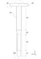
- FIG. 5 is an enlarged side view showing a cannula provided in the administration device of the drug solution administration system shown in FIG. 1.
- FIG. 5 is an enlarged axial sectional view showing a cannula provided in the administration device shown in FIG. 1.
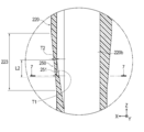
- It is an enlarged view of the area surrounded by the broken line 6 of FIG.
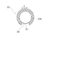
- It is an end view along the line 7-7 of FIG.
- It is a schematic diagram which shows the state which the drug solution is administered into the living body through the tip opening of the cannula provided in the administration instrument shown in FIG.
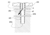
- FIG. 1 It is a schematic diagram which shows the state in which the thin-walled portion of the cannula provided in the administration device shown in FIG. 1 is cleaved, and the drug solution is administered into the living body from the cleaved thin-walled portion. It is a side view which shows the cannula which concerns on the modification. It is an end view along the line 10-10 of FIG.
- FIGS. 1 to 8B are diagrams provided for explaining the drug solution administration system 10, the drug solution administration device 100, and the administration device 200 according to the embodiment of the present invention.
- the arrow X attached to each figure indicates the "longitudinal direction" of the drug solution administration device 100 and the administration device 200, and the arrow Y indicates the “width direction (depth direction)” of the drug solution administration device 100 and the administration device 200.
- Z indicates the "height direction (axial direction of the cannula 220)" of the drug solution administration device 100 and the administration device 200.
- the cross-sectional view shown in FIG. 3 is a vertical cross-sectional view (cross-sectional view of the XZ cross section) of the drug solution administration device 100 and the administration instrument 200.
- "a to b" indicating a range means “a or more and b or less”.
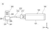
- the drug solution administration system 10 is used to administer the drug solution in vivo. As shown in FIG. 1, the drug solution administration system 10 includes a drug solution administration device 100 and an administration device 200.
- the puncture portion 230 of the drug solution administration device 100 and the administration device 200 is attached to the body surface H of the user.
- the part of the body of the user to which the drug solution administration device 100 and the puncture portion 230 are attached is not particularly limited, and is, for example, the abdomen, the deltoid muscle, or the thigh.
- the chemical solution (not shown) filled in the chemical solution container 110 included in the chemical solution administration device 100 is pressed by the pusher 130 for a relatively long time (for example, about several minutes to several hours). ) Can be continuously administered in vivo.
- the drug solution administration system 10 may intermittently administer the drug solution into the living body.
- the chemical solution administration device 100 includes a chemical solution container 110 filled with a chemical solution, a housing 120 for holding the chemical solution container 110, and a pusher 130 for pushing the chemical solution in the chemical solution container 110 into a cannula 220 described later. ,have.
- the chemical solution container 110 is composed of a cylinder having a cavity 111 filled with the chemical solution.
- the tip of the pusher 130 is inserted into the cavity 111 of the chemical container 110.
- a gasket 131 is arranged at the tip of the pusher 130.
- the gasket 131 can be made of, for example, a resin material such as a rubber material or an elastomer.
- the outer peripheral portion of the gasket 131 is in close contact with the inner peripheral surface of the chemical liquid container 110 in a liquid-tight manner, thereby sealing the base end side of the gasket 131 in a liquid-tight manner.
- the chemical solution container 110 is composed of a so-called prefilled chemical solution container. Therefore, the chemical solution is pre-filled in the cavity 111 of the chemical solution container 110.
- the drug solution include protein preparations, narcotic analgesics, diuretics and the like.
- a sealing member 112 for preventing the chemical liquid from leaking is arranged at the tip opening (discharge port) of the chemical liquid container 110.
- the tip opening of the chemical solution container 110 is arranged so as to project to the outside of the housing 120.
- the pusher 130 is configured to be movable forward with respect to the chemical solution container 110 toward the tip end side (left side in FIG. 3) of the chemical solution container 110 by a forward mechanism (not shown).
- the pusher 130 pushes the chemical solution out of the cavity 111 of the chemical solution container 110 into the cannula 220 by advancing with respect to the chemical solution container 110.
- a battery that supplies electric power required for each operation of the chemical administration device 100, a substrate on which a control unit that controls a motor is attached, a drive mechanism for driving a forward mechanism, and the like (all not shown). Is housed.
- the drug solution administration device 100 is configured as a patch type to be used by being attached to the body surface (skin) H of the user.
- a sheet-shaped attachment portion (not shown) that can be attached to the body surface is provided on the contact surface (bottom surface) 121 of the housing 120 of the chemical solution administration device 100.
- a peelable protective sheet is attached to the attachment surface of the attachment portion.
- the administration device 200 is configured to be connectable to the drug solution administration device 100. As shown in FIG. 3, the administration device 200 has a connection portion 210, a cannula 220, a puncture portion 230, and a puncture assisting tool 240. Hereinafter, each part of the administration device 200 will be described.
- the connecting portion 210 is configured to be connectable to the drug solution administration device 100.
- the connecting portion 210 is formed with a lumen 210a that can communicate with the lumen 111 of the chemical solution container 110 in a state of being connected to the chemical solution administration device 100.
- the connecting portion 210 has a connector 211 that can be connected to the vicinity of the tip end portion of the chemical solution container 110, and a tube 212 that connects the connector 211 and the puncture portion 230.
- the connector 211 is a connecting needle tube 214 having a mounting portion 213 that is externally fitted near the tip of the chemical solution container 110 projecting to the outside of the housing 120 and a needle tip capable of penetrating the sealing member 112. And a communication portion 215 that is connected to the mounting portion 213 and holds the connecting needle tube 214 and the tube 212.
- the communication portion 215 is formed with a lumen 215a that communicates the lumen 214a of the connecting needle tube 214 and the lumen 212c of the tube 212.
- One end 212a of the tube 212 (hereinafter referred to as the first end 212a) is held by the communication portion 215.
- the other end portion 212b of the tube 212 (hereinafter referred to as the second end portion 212b) is held by the puncture portion 230 in a state of being inserted into the communication passage 233 of the puncture portion 230 described later.
- the connector 211 is connected to the drug solution administration device 100 via the mounting portion 213, and the needle tip of the connecting needle tube 214 seals the drug solution administration device 100.
- the lumen 210a of the connecting portion 210 is composed of the lumen 214a of the connecting needle tube 214, the lumen 215a of the communicating portion 215, and the lumen 212c of the tube 212.
- the configuration of the connecting portion is not particularly limited as long as it is configured to be connectable to the drug solution administration device and a lumen that can communicate with the lumen of the drug solution container is formed while being connected to the drug solution administration device.
- the puncture portion 230 is arranged at the lower end of the puncture portion 230, and the contact surface 231 (bottom surface) that contacts the surface of the living body and the tip (lower end) of the cannula 220 that is arranged above the contact surface 231 project from the contact surface 231.
- it has a cannula holding portion 232 for holding the cannula 220, and a communication passage 233 communicating with the lumen 220b of the cannula 220 and the lumen 210a of the connecting portion 210.
- the direction of protrusion of the cannula 220 from the contact surface 231 is substantially perpendicular to the contact surface 231. Therefore, the axes of the cannula 220 intersect substantially perpendicular to the contact surface 231.
- the administration device 200 is configured as a patch type to be used by being attached to the body surface H of the user, similarly to the drug solution administration device 100.
- the contact surface 231 is provided with a sheet-shaped attachment portion (not shown) that can be attached to the body surface.
- a peelable protective sheet (not shown) is attached to the attachment surface of the attachment portion.
- the communication passage 233 includes a first flow path 233a extending from the base end of the cannula 220 along the axis of the cannula 220, and a second flow path 233b that communicates the first flow path 233a with the second end portion 212b of the tube 212. ,have.
- a sealing member 234 is arranged to prevent the chemical liquid from leaking from the base end of the communication passage 233 after the introduction needle 241 described later is removed from the communication passage 233. ing.
- the puncture aid 240 is attached to the puncture portion 230 when the drug solution is sent to the user.
- the puncture aid 240 holds the introduction needle (inner needle) 241.
- the introduction needle 241 can be composed of, for example, a metal needle.
- the puncture aid 240 can be prepared, for example, in a state of being attached to the puncture portion 230 in advance before using the drug solution administration system 10.
- the introduction needle 241 is inserted into the communication passage 233 of the puncture portion 230 and the lumen 220b of the cannula 220 with the puncture aid 240 attached to the puncture portion 230. Further, in this state, the tip of the introduction needle 241 protrudes from the tip of the cannula 220.
- the puncture aid 240 is removed from the puncture portion 230 after the cannula 220 is punctured into the living body.
- the introduction needle 241 is removed from the lumen 220b of the cannula 220 when the puncture aid 240 is removed from the puncture portion 230.
- the lumen 220b of the cannula 220 communicates with the communication passage 233 of the puncture portion 230.
- the lumen 220b of the cannula 220 communicates with the lumen 210a of the connecting portion 210 via the communication passage 233.
- the pusher 130 of the drug solution administration device 100 advances in the drug solution container 110, so that the drug solution filled in the cavity 111 of the drug solution container 110 is connected to the cavity 210a of the connection portion 210 and the puncture portion 230.
- the liquid is sent to the lumen 220b of the cannula 220 via the passage 233.
- the cannula 220 is formed with a lumen 220b that axially penetrates the cannula 220.
- the cannula 220 is punctured into a living body with the introduction needle 241 inserted in the lumen 220b.
- the cannula 220 may be configured so that the living body is punctured only by the cannula 220.
- Cannula 220 is punctured on the body surface H of the user.
- the side inserted into the living body in the axial direction of the cannula is referred to as the distal end side, and the opposite side thereof is referred to as the proximal end side.
- a certain range in the axial direction from the tip (leading edge) is referred to as a tip portion, and a constant range in the axial direction from the proximal end (most proximal end) is referred to as a proximal end portion.
- the opening on the tip side of the cannula is referred to as a tip opening.
- the cannula 220 is connected to the distal end portion 221 whose outer diameter gradually decreases from the proximal end side to the distal end side and the proximal end of the distal end portion 221 and is connected to the proximal end side to the distal end side.
- a first outer diameter constant portion 222 having a substantially constant outer diameter toward the surface, and a tapered portion 223 connected to the proximal end of the first outer diameter constant portion 222 and gradually decreasing in outer diameter from the proximal end side toward the distal end side.
- a second outer diameter constant portion 224 which is connected to the proximal end of the tapered portion 223 and has a substantially constant outer diameter from the proximal end side to the distal end side.
- the cannula 220 further has a proximal end portion 225 that is connected to the proximal end of the second outer diameter constant portion 224 and whose outer diameter gradually increases from the distal end side to the proximal end side.
- the base end portion 225 is formed so that not only the outer diameter but also the inner diameter gradually increases from the tip end side toward the base end side. Therefore, the cannula 220 can efficiently flow the chemical solution from the communication passage 233 to the base end portion.
- the cannula 220 has a thin portion 250 having a wall thickness smaller than that of other portions of the cannula 220 except the tip portion 221.
- the thin-walled portion 250 is formed in a part of the circumferential direction ⁇ of the cannula 220 on the proximal end side of the tip opening 220a and on the distal end side of the contact surface 231.
- the thin portion 250 is cleaved when it receives a pressure higher than a set pressure.
- the "set pressure" means the internal pressure of the cannula 220 when the tip opening 220a is closed.
- the set pressure is not particularly limited, but is, for example, 32 MPa to 360 MPa.
- the thin portion 250 has an inner recess 251 formed in a part of the circumferential direction ⁇ of the inner peripheral surface of the cannula 220.
- the inner recess 251 is formed on the inner peripheral surface of the tapered portion 223.
- the mold clamping unit includes a mold in which a cavity corresponding to the outer shape of the cannula 220 is formed, and a core having an outer shape corresponding to the inner cavity 220b of the cannula 220 (both are not shown). That is, the core is formed with a convex portion having an outer diameter corresponding to the inner concave portion 251, and there is a step between the tip of the convex portion and the portion of the core that is axially adjacent to the tip of the convex portion.
- the injection unit heats and melts the resin material and pours it into the mold of the molding unit.
- the mold is then cooled and the cured molded product (cannula 220) is removed from the mold and core.
- the core can be easily removed from the base end side of the molded product.
- the inner concave portion 251 can be formed when the cannula 220 is injection-molded, it is not necessary to further perform processing for forming the inner concave portion 251 after the injection molding of the cannula 220.
- the distance L1 (see FIG. 5) from the base end of the thin portion 250 (inner recess 251) to the contact surface 231 is not particularly limited and can be appropriately set according to the puncture site of the living body.
- the distance L1 from the base end of the thin portion 250 to the contact surface 231 can be, for example, 2.0 mm to 10.5 mm.
- the cannula 220 may puncture the blood vessel.
- the axial dimension L2 (see FIGS. 5 and 6) of the thin portion 250 is not particularly limited, but can be, for example, 0.2 mm to 2.0 mm.
- the dimension L3 (see FIG. 7) in the direction orthogonal to the axial direction of the thin portion 250 is not particularly limited, but may be, for example, 0.2 mm to 0.4 mm.
- the minimum wall thickness T1 (see FIG. 6) of the thin portion 250 is not particularly limited, but can be set to, for example, 0.01 mm to 0.04 mm. By configuring the cannula 220 in this way, the thin-walled portion 250 can be easily cleaved when the tip opening 220a is closed.
- the ratio of the minimum wall thickness T1 of the thin wall portion 250 to the wall thickness T2 of the adjacent portion adjacent to the thin wall portion 250 of the cannula 220 is not particularly limited, but can be set to, for example, 0.05 to 0.40.
- the thin-walled portion 250 can be easily cleaved when the tip opening 220a is closed.
- adjacent part means the part which is adjacent to the thin part in the cannula in the axial direction or the circumferential direction.
- the adjacent portion means a portion of the tapered portion 223 excluding the thin portion 250 (inner recess 251).
- the material constituting the cannula 220 is not particularly limited as long as it is biocompatible and breaks when subjected to a set pressure, but is not particularly limited, but is polytetrafluoroethylene, tetrafluoroethylene / ethylene copolymer resin, and polyethylene. It can be formed of a known resin material such as.
- the puncture aid 240 is attached to the puncture portion 230 of the administration device 200, and the cannula 220 is punctured into the living body with the tip of the introduction needle 241 protruding from the tip of the cannula 220. .. Then, the contact surface 231 of the puncture portion 230 is attached to the body surface of the user.
- the puncture aid 240 is removed, and the puncture portion 230 is left on the body surface H of the user with the cannula 220 indwelled in the living body. ..
- the pusher 130 of the drug solution administration device 100 advances in the drug solution container 110, so that the drug solution filled in the cavity 111 of the drug solution container 110 of the drug solution administration device 100 is punctured with the cavity 210a of the connection portion 210.
- the liquid is sent to the lumen 220b of the cannula 220 via the communication passage 233 of the portion 230.
- the introduction needle 241 protrudes from the tip of the cannula 220. Therefore, as shown in FIG. 8A, when the introduction needle 241 is removed from the lumen 220b of the cannula 220, a space S is formed between the tip of the cannula 220 and the living tissue. Therefore, the drug solution administration device 100 can easily administer the drug solution into the living body through the tip opening 220a of the cannula 220, as shown by the arrow a1 in FIG. 8A.
- the tip surface of the cannula 220 is strongly pressed against the living body tissue, and the tip opening 220a may be blocked.
- the puncture portion 230 is strongly pressed against the living body, the tip surface of the cannula 220 is strongly pressed against the living body, whereas the outer peripheral surface of the cannula 220 is in contact with the living body but is strongly pressed against the living body as compared with the tip surface. Not done.
- the cannula 220 easily cleaves the thin-walled portion 250 formed on the outer peripheral surface of the cannula 220 when the tip opening 220a of the cannula 220 is closed and the internal pressure of the cannula 220 becomes equal to or higher than the set pressure. be able to. Then, the drug solution administration device 100 can administer the drug solution to the living body through the cleaved thin-walled portion 250 as shown by the arrow a2 in FIG. 8B.
- the tip opening 220a is cannulated not only because the puncture portion 230 is strongly pressed against the living body by an external force, but also because, for example, a thrombus or the like occludes the tip opening 220a, or the user moves the body. It can also be blocked by the 220 being bent in the living body.
- the administration device 200 is an administration device that can be connected to the drug solution administration device 100 including the drug solution container 110 filled with the drug solution.
- the administration device 200 has a connection portion 210, a cannula 220, and a puncture portion 230.
- the connecting portion 210 can be connected to the chemical solution administration device 100, and a lumen 210 a that can communicate with the lumen 111 of the chemical solution container 110 is formed while being connected to the chemical solution administration device 100.
- the cannula 220 has a tip opening 220a and is punctured by a living body.
- the puncture portion 230 is connected to a contact surface 231 that contacts the body surface H of the living body, a cannula holding portion 232 that holds the cannula 220 so that the tip of the cannula 220 protrudes from the contact surface 231, and a lumen 220b of the cannula 220. Includes a communication passage 233 communicating with the lumen 210a of the portion 210.
- the cannula 220 has a thin portion 250.
- the thin-walled portion 250 is formed in a part of the circumferential direction ⁇ of the cannula 220 on the proximal end side of the tip opening 220a and on the distal end side of the contact surface 231 and is smaller than other portions except the tip portion 221 of the cannula 220. It has a wall thickness and cleaves when it receives a pressure higher than the set pressure.
- the administration device 200 when the tip opening 220a of the cannula 220 is closed, the internal pressure of the cannula 220 becomes a pressure equal to or higher than the set pressure, so that the thin portion 250 is cleaved and the thin portion 250 is cleaved through the cleaved thin portion 250.
- the drug solution can be administered in vivo. Therefore, according to the administration device 200, the drug solution can be administered even when the tip opening 220a of the cannula 220 is occluded.
- the thin portion 250 has an inner recess 251 formed in a part of the circumferential direction ⁇ of the inner peripheral surface of the cannula 220. Therefore, when the tip opening 220a of the cannula 220 is closed, the inner recess 251 can be cleaved and the drug solution can be administered into the living body. Further, since the inner recess 251 is formed on the inner peripheral surface of the cannula 220, the cannula 220 can be smoothly punctured into the living body.
- the cannula 220 has a tapered portion 223 in which the outer diameter of the cannula 220 gradually decreases from the proximal end side toward the distal end side on the proximal end side of the distal end opening 220a and on the distal end side of the contact surface 231. Is formed on the inner peripheral surface of the tapered portion 223. According to such a configuration, the cannula 220 provided with the inner recess 251 can be easily formed by injection molding. Therefore, it is not necessary to further process the inner recess 251 after injection molding of the cannula 220.
- the minimum wall thickness T1 of the thin portion 250 is 0.1 mm to 0.4 mm. According to the cannula 220 configured in this way, the thin-walled portion 250 is easily cleaved when the tip opening 220a of the cannula 220 is closed.
- the ratio of the minimum wall thickness T1 of the thin wall portion 250 to the minimum wall thickness of the adjacent portion adjacent to the thin wall portion 250 of the cannula 220 is 0.05 to 0.40. According to the cannula 220 configured in this way, the thin-walled portion 250 is easily cleaved when the tip opening 220a of the cannula 220 is closed.
- the set pressure is 32 MPa to 360 MPa. According to the cannula 220 configured in this way, the thin-walled portion 250 is easily cleaved when the tip opening 220a of the cannula 220 is closed.
- the drug solution administration system 10 includes the above-mentioned administration device 200 and the drug solution administration device 100.
- the chemical solution administration device 100 includes a chemical solution container 110, a housing 120 for holding the chemical solution container 110, and a pusher 130 for pushing the chemical solution in the chemical solution container 110 into the cannula 220.
- the drug solution administration device 100 can administer the drug solution into the living body through the cleaved thin-walled portion 250.
- (Modification example) 9 and 10 are diagrams showing the cannula 320 according to the modified example.
- the cannula 320 is formed with a lumen 320b that penetrates the cannula 320 in the axial direction of the cannula 320.
- the portion of the cannula 320 on the distal end side of the contact surface 231 may be configured to have a constant inner diameter from the proximal end side toward the distal end side.
- the portion of the cannula 320 on the tip end side of the contact surface 231 may have a constant outer diameter from the base end side to the tip end side, except for the thin-walled portion 350 described later.
- the outer diameter of the cannula is not particularly limited as long as the thin portion is formed.
- the cannula 320 has a thin portion 350 having a wall thickness smaller than that of other portions.
- the thin-walled portion 350 is formed in a part of the circumferential direction ⁇ of the cannula 320 on the proximal end side of the tip opening 320a and on the distal end side of the contact surface 231.
- the thin portion 350 is cleaved when it receives a pressure higher than a set pressure.
- the thin-walled portion 350 has an outer recess 351 formed in a part of the circumferential direction ⁇ of the outer peripheral surface of the cannula 320.
- the outer recess 351 is not particularly limited, but can be formed by laser processing or the like.
- the outer recess 351 separates from the living tissue with the cannula 320 indwelling in the living body. Therefore, when the tip opening 320a of the cannula 320 is closed, the cannula 320 can easily open the outer recess 351.
- the thin-walled portion 350 has an outer recess 351 formed in a part of the circumferential direction ⁇ of the outer peripheral surface of the cannula 320. Therefore, when the tip opening 320a of the cannula 320 is closed, the outer recess 351 can be cleaved and the drug solution can be administered into the living body. Further, when the tip opening 320a of the cannula 320 is closed, the outer recess 351 is separated from the living tissue with the cannula 320 indwelled in the living body. Therefore, the cannula 320 can easily cleave the outer recess 351.
- the present invention is not limited to each of the described configurations, and may be appropriately modified based on the description of the claims. It is possible.
- each member constituting the administration device and the drug solution administration system are not particularly limited as long as the effects of the present invention are exhibited. , Can be changed and replaced at will. Further, it is also possible to appropriately add arbitrary constituent members and the like not particularly described in the specification to the administration device and the drug solution administration system.
- the thin-walled portion may have both an inner recess and an outer recess. Further, for example, the thin-walled portion may have a plurality of inner recesses (or outer recesses) in the circumferential direction or the axial direction.
- Chemical administration system 100 drug solution administration device, 110 chemical container, 111 Inner cavity of chemical container, 120 housing, 130 pusher, 200 administration device, 210 connection, 210a Connection cavity, 220, 320 cannula, 220a, 320a Cannula tip opening, 220b, 320b Cannula lumen 221 Cannula tip, 223 taper part, 230 puncture site, 231 contact surface, 232 Cannula holder, 233 consecutive passages, 240 Puncture aid, 241 introduction needle, 250, 350 thin part, 251 Inner recess, 351 outer recess, H body surface, T1 Minimum wall thickness of thin part, Minimum wall thickness of T2 adjacent part, ⁇ Circumferential direction.
Landscapes
- Health & Medical Sciences (AREA)
- Life Sciences & Earth Sciences (AREA)
- Hematology (AREA)
- Animal Behavior & Ethology (AREA)
- Engineering & Computer Science (AREA)
- Anesthesiology (AREA)
- Biomedical Technology (AREA)
- Heart & Thoracic Surgery (AREA)
- Veterinary Medicine (AREA)
- Public Health (AREA)
- General Health & Medical Sciences (AREA)
- Vascular Medicine (AREA)
- Pulmonology (AREA)
- Biophysics (AREA)
- Infusion, Injection, And Reservoir Apparatuses (AREA)
- Media Introduction/Drainage Providing Device (AREA)
Abstract
【課題】カニューレの先端開口部が閉塞した場合にも薬液を投与することができる投与器具を提供する。 【解決手段】投与器具200は、薬液が充填される薬液容器110を備える薬液投与装置100に接続可能な投与器具である。投与器具200は、薬液投与装置に接続可能であり、薬液投与装置に接続された状態で薬液容器の内腔111と連通可能な内腔210aが形成された接続部210と、先端開口部220aを有し、生体に穿刺されるカニューレ220と、体表面Hに接触する接触面231と、カニューレの先端が接触面から突出するようにカニューレを保持するカニューレ保持部232と、カニューレの内腔220bおよび接続部の内腔に連通した連通路233と、を含む穿刺部230と、を有する。カニューレは、先端開口部よりも基端側および接触面よりも先端側においてカニューレの周方向θの一部に形成され、カニューレの先端部231を除く他の部位よりも小さい肉厚を備えるとともに設定された圧力以上の圧力を受けると開裂する薄肉部250を有する。
Description
本発明は、投与器具、および当該投与器具と薬液投与装置を有する薬液投与システムに関する。
従来、薬液容器に充填した薬液を押し子の押圧作用により生体内に投与するシリンジポンプ型の薬液投与装置が知られている。この種の薬液投与装置を使用した薬液の投与を行う際、カニューレ(カテーテル)を備え、薬液投与装置に接続可能な投与器具を使用することがある(特許文献1参照)。
特許文献1に記載の投与器具は、使用者の体表面に接触させられる接触面(底面)から突出するようにカニューレを保持する穿刺部(カニューレハウジング)を有する。カニューレには導入針を挿通可能な内腔が形成されており、カニューレは、導入針が先端から突出した状態で生体に穿刺される。カニューレを生体に穿刺した後、導入針はカニューレの内腔から抜去される。
生体に穿刺する際に導入針はカニューレの先端から突出しているため、導入針を抜去した後、カニューレの先端と生体の穿刺部位との間には空間が形成される。そのため、薬液投与装置は、カニューレの先端開口部から生体内に薬液を容易に投与することができる。
しかしながら、例えば外力によって穿刺部が生体に押し付けられた場合、カニューレの先端開口部が生体組織に押し付けられて閉塞する場合がある。カニューレの先端開口部が閉塞した場合、薬液投与装置は生体内に薬液を投与することができなくなる。
本発明は上記のような課題を鑑みてなされたものであり、カニューレの先端開口部が閉塞した場合にも薬液を投与することができる投与器具、および当該投与器具と薬液投与装置を有する薬液投与システムを提供することを目的とする。
本願発明に係る投与器具は、薬液が充填される薬液容器を備える薬液投与装置に接続可能な投与器具であって、前記薬液投与装置に接続可能であり、前記薬液投与装置に接続された状態で前記薬液容器の内腔と連通可能な内腔が形成された接続部と、先端開口部を有し、生体に穿刺されるカニューレと、前記生体の体表面に接触する接触面と、前記カニューレの先端が前記接触面から突出するように前記カニューレを保持するカニューレ保持部と、前記カニューレの内腔および前記接続部の内腔に連通した連通路と、を含む穿刺部と、を有し、前記カニューレは、前記先端開口部よりも基端側および前記接触面よりも先端側において前記カニューレの周方向の一部に形成され、前記カニューレの先端部を除く他の部位よりも小さい肉厚を備えるとともに設定された圧力以上の圧力を受けると開裂する薄肉部を有する。
また、本発明に係る薬液投与システムは、上記の投与器具と、前記薬液容器、前記薬液容器を保持するハウジング、および前記薬液容器内の前記薬液を前記カニューレへ押し出す押し子を備える前記薬液投与装置と、を有する。
本発明の投与器具および薬液投与システムによれば、カニューレの先端開口部が閉塞した場合にも薬液を投与することができる。
以下、添付した図面を参照しながら、本発明の実施形態を説明する。なお、以下の記載は特許請求の範囲に記載される技術的範囲や用語の意義を限定するものではない。また、図面の寸法比率は説明の都合上誇張されており、実際の比率とは異なる場合がある。
図1~図8Bは、本発明の一の実施形態に係る薬液投与システム10、薬液投与装置100、および投与器具200の説明に供する図である。各図に付した矢印Xは、薬液投与装置100および投与器具200の「長手方向」を示し、矢印Yは、薬液投与装置100および投与器具200の「幅方向(奥行方向)」を示し、矢印Zは、薬液投与装置100および投与器具200の「高さ方向(カニューレ220の軸方向)」を示す。また、図3に示す断面図は、薬液投与装置100および投与器具200の縦方向断面図(X-Z断面の断面図)である。また、本明細書において、範囲を示す「a~b」は「a以上b以下」を意味する。
(薬液投与システム)
薬液投与システム10は、薬液を生体内に投与するために使用される。図1に示すように、薬液投与システム10は、薬液投与装置100と、投与器具200と、を有する。
薬液投与システム10は、薬液を生体内に投与するために使用される。図1に示すように、薬液投与システム10は、薬液投与装置100と、投与器具200と、を有する。
図2および図3に示すように、薬液投与システム10を使用した薬液の投与を行う際、薬液投与装置100および投与器具200の穿刺部230は、使用者の体表面Hに取り付けられる。薬液投与装置100および穿刺部230を取り付ける使用者の身体の部位は特に限定されないが、例えば、腹部、三角筋部や大腿部である。
薬液投与システム10は、例えば、薬液投与装置100が備える薬液容器110内に充填された薬液(図示省略)を、押し子130による押圧作用により、比較的長い時間(例えば、数分~数時間程度)をかけて持続的に生体内に投与することができる。なお、薬液投与システム10は、薬液を間欠的に生体内に投与してもよい。
(薬液投与装置)
薬液投与装置100は、図3に示すように、薬液が充填される薬液容器110と、薬液容器110を保持するハウジング120と、薬液容器110内の薬液を後述するカニューレ220へ押し出す押し子130と、を有している。
薬液投与装置100は、図3に示すように、薬液が充填される薬液容器110と、薬液容器110を保持するハウジング120と、薬液容器110内の薬液を後述するカニューレ220へ押し出す押し子130と、を有している。
薬液容器110は、薬液が充填される内腔111を備える筒体で構成している。薬液容器110の内腔111には、押し子130の先端部が挿入されている。押し子130の先端部にはガスケット131を配置している。ガスケット131は、例えば、ゴム材やエラストマー等の樹脂材料で構成することができる。ガスケット131は、ガスケット131の外周部が薬液容器110の内周面と液密に密着することにより、ガスケット131の基端側を液密に封止する。
薬液容器110は、いわゆるプレフィルド型の薬液容器で構成している。そのため、薬液は、薬液容器110の内腔111内に予め充填されている。薬液としては、例えば、タンパク質製剤、麻薬性鎮痛薬、利尿薬等が挙げられる。
薬液容器110の先端開口部(吐出口)には、薬液が漏洩するのを防止するための封止部材112を配置している。薬液容器110の先端開口部は、ハウジング120の外部に突出するように配置している。
押し子130は、図示省略する前進機構により薬液容器110の先端側(図3の左側)へ向けて薬液容器110に対して前進移動可能に構成している。押し子130は、薬液容器110に対して前進することにより、薬液容器110の内腔111から薬液をカニューレ220へ押し出す。
ハウジング120内には、薬液投与装置100の各動作に必要な電力を供給する電池、モータを制御する制御部が取り付けられた基板、前進機構を駆動するための駆動機構等(いずれも図示省略)が収容されている。
図2に示すように、薬液投与装置100は、使用者の体表面(皮膚)Hに貼り付けて使用するパッチタイプとして構成している。薬液投与装置100のハウジング120の接触面(底面)121には、体表面に貼着可能なシート状の貼着部(図示省略)を設けている。薬液投与装置100を使用者に取り付ける前の初期状態において、貼着部の貼着面には剥離可能な保護シートが取り付けられる。
(投与器具)
図3に示すように、投与器具200は、薬液投与装置100に接続可能に構成している。投与器具200は、図3に示すように、接続部210と、カニューレ220と、穿刺部230と、穿刺補助具240と、を有している。以下、投与器具200の各部について説明する。
図3に示すように、投与器具200は、薬液投与装置100に接続可能に構成している。投与器具200は、図3に示すように、接続部210と、カニューレ220と、穿刺部230と、穿刺補助具240と、を有している。以下、投与器具200の各部について説明する。
(接続部)
接続部210は、薬液投与装置100に接続可能に構成している。接続部210は、薬液投与装置100に接続された状態で薬液容器110の内腔111と連通可能な内腔210aが形成されている。具体的には、接続部210は、本実施形態では、薬液容器110の先端部付近に接続可能なコネクタ211と、コネクタ211と穿刺部230と接続するチューブ212と、を有している。
接続部210は、薬液投与装置100に接続可能に構成している。接続部210は、薬液投与装置100に接続された状態で薬液容器110の内腔111と連通可能な内腔210aが形成されている。具体的には、接続部210は、本実施形態では、薬液容器110の先端部付近に接続可能なコネクタ211と、コネクタ211と穿刺部230と接続するチューブ212と、を有している。
コネクタ211は、本実施形態では、ハウジング120の外部に突出した薬液容器110の先端部付近に外嵌される装着部213と、封止部材112を刺通可能な針先を備える接続用針管214と、装着部213に接続され、接続用針管214およびチューブ212を保持する連通部215と、を有する。連通部215には、接続用針管214の内腔214aとチューブ212の内腔212cを連通する内腔215aが形成されている。
チューブ212の一の端部212a(以下第1端部212aと称する)は、連通部215に保持されている。チューブ212の他の端部212b(以下第2端部212bと称する)は、後述する穿刺部230の連通路233に挿入された状態で穿刺部230に保持されている。
チューブ212の内腔212cと薬液容器110の内腔111は、コネクタ211が装着部213を介して薬液投与装置100に接続され、かつ、接続用針管214の針先が薬液投与装置100の封止部材112を貫通した状態(図3に示す状態)で、互いに連通される。このように接続部210の内腔210aは、本実施形態では、接続用針管214の内腔214a、連通部215の内腔215a、およびチューブ212の内腔212cによって構成している。
ただし、接続部の構成は、薬液投与装置に接続可能に構成され、薬液投与装置に接続された状態で薬液容器の内腔と連通可能な内腔が形成されている限り、特に限定されない。
(穿刺部)
穿刺部230は、穿刺部230の下端に配置され、生体表面に接触する接触面231(底面)と、接触面231よりも上方に配置されカニューレ220の先端(下端)が接触面231から突出するようにカニューレ220を保持するカニューレ保持部232と、カニューレ220の内腔220bおよび接続部210の内腔210aに連通した連通路233と、を有する。
穿刺部230は、穿刺部230の下端に配置され、生体表面に接触する接触面231(底面)と、接触面231よりも上方に配置されカニューレ220の先端(下端)が接触面231から突出するようにカニューレ220を保持するカニューレ保持部232と、カニューレ220の内腔220bおよび接続部210の内腔210aに連通した連通路233と、を有する。
カニューレ220の接触面231からの突出方向は、接触面231に対して略垂直である。したがって、カニューレ220の軸は、接触面231に対して略垂直に交わる。
投与器具200は、薬液投与装置100と同様に、使用者の体表面Hに貼り付けて使用するパッチタイプとして構成している。接触面231には、体表面に貼着可能なシート状の貼着部(図示省略)を設けている。投与器具200を使用者に取り付ける前の初期状態において、貼着部の貼着面には剥離可能な保護シート(図示省略)が取り付けられる。
連通路233は、カニューレ220の基端からカニューレ220の軸に沿って延びる第1流路233aと、第1流路233aとチューブ212の第2端部212bとを連通する第2流路233bと、を有している。
連通路233の基端付近(上端付近)には、後述する導入針241が連通路233から抜去された後に連通路233の基端から薬液が漏洩するのを防止する封止部材234を配置している。
(穿刺補助部)
図3に示すように、穿刺補助具240は、使用者への薬液の送液に際して、穿刺部230に取り付けられる。穿刺補助具240は、導入針(内針)241を保持している。
図3に示すように、穿刺補助具240は、使用者への薬液の送液に際して、穿刺部230に取り付けられる。穿刺補助具240は、導入針(内針)241を保持している。
導入針241は、例えば、金属針で構成することが可能である。
穿刺補助具240は、例えば、薬液投与システム10の使用前に、穿刺部230に予め取り付けた状態で準備することができる。導入針241は、穿刺補助具240を穿刺部230に取り付けた状態において、穿刺部230の連通路233およびカニューレ220の内腔220bに挿入される。また、この状態において、導入針241の先端はカニューレ220の先端から突出する。カニューレ220が導入針241によって挿通された状態で生体を穿刺することにより、カニューレ220に折れ等が生じるのを防止しつつ、カニューレ220を生体に刺入することが可能になる。
穿刺補助具240は、カニューレ220を生体に穿刺した後、穿刺部230から取り外される。導入針241は、穿刺部230から穿刺補助具240が取り外されると、カニューレ220の内腔220bから抜去される。カニューレ220の内腔220bから導入針241が抜去されると、カニューレ220の内腔220bが穿刺部230の連通路233と連通する。また、カニューレ220の内腔220bは、連通路233を介して接続部210の内腔210aと連通する。この状態で薬液投与装置100の押し子130が薬液容器110内を前進することにより、薬液容器110の内腔111に充填された薬液は、接続部210の内腔210a、および穿刺部230の連通路233を経由してカニューレ220の内腔220bへ送液される。
(カニューレ)
カニューレ220は、カニューレ220を軸方向に貫通する内腔220bが形成されている。カニューレ220は、本実施形態では、内腔220bに導入針241が挿入された状態で生体への穿刺がなされる。ただし、カニューレ220は、カニューレ220のみによって生体への穿刺がなされるように構成してもよい。
カニューレ220は、カニューレ220を軸方向に貫通する内腔220bが形成されている。カニューレ220は、本実施形態では、内腔220bに導入針241が挿入された状態で生体への穿刺がなされる。ただし、カニューレ220は、カニューレ220のみによって生体への穿刺がなされるように構成してもよい。
カニューレ220は、使用者の体表面Hに穿刺される。本明細書では、カニューレの軸方向において生体に挿入される側を先端側と称し、その反対側を基端側と称する。また、カニューレの各部において、先端(最先端)から軸方向に一定の範囲を先端部と称し、基端(最基端)から軸方向に一定の範囲を基端部と称する。また、カニューレの先端側の開口部を先端開口部と称する。
図4に示すように、カニューレ220は、本実施形態では、基端側から先端側に向かって外径が漸減する先端部221と、先端部221の基端に連なり、基端側から先端側に向かって略一定の外径を有する第1外径一定部222と、第1外径一定部222の基端に連なり、基端側から先端側に向かって外径が漸減するテーパ部223と、テーパ部223の基端に連なり、基端側から先端側に向かって略一定の外径を有する第2外径一定部224と、を有する。図3に示すように、カニューレ220は、第2外径一定部224の基端に連なり、先端側から基端側に向かって外径が漸増する基端部225をさらに有する。
先端部221およびテーパ部223は、基端側から先端側に向かって外径が漸減するため、術者はカニューレ220を容易に生体に穿刺できる。基端部225は、外径だけでなく内径も先端側から基端側に向かって漸増するように形成されている。そのため、カニューレ220は、連通路233から基端部へ効率良く薬液を流入させることができる。
図5および図7に示すように、カニューレ220は、カニューレ220において先端部221を除く他の部位よりも小さい肉厚を備える薄肉部250を有する。薄肉部250は、先端開口部220aよりも基端側および接触面231よりも先端側においてカニューレ220の周方向θの一部に形成されている。薄肉部250は、設定された圧力以上の圧力を受けると開裂する。
カニューレ220の先端開口部220aが閉塞された場合、薬液を先端開口部220aから排出することができなくなるため、カニューレ220の内圧は高まる。本明細書において、「設定された圧力」とは、先端開口部220aの閉塞時のカニューレ220の内圧を意味する。設定された圧力は、特に限定されないが、例えば、32MPa~360MPaである。
図6および図7に示すように、薄肉部250は、本実施形態では、カニューレ220の内周面の周方向θの一部に形成された内側凹部251を有する。内側凹部251は、テーパ部223の内周面に形成されている。図6に示すように、内側凹部251の先端とテーパ部223において内側凹部251の先端に軸方向に隣接する部分には段差が存在する一方、内側凹部251の基端とテーパ部223において内側凹部251の基端に軸方向に隣接する部分には段差が存在しない。このような構成によれば、内側凹部251を備えるカニューレ220を、射出成形によって簡便に形成することができる。
ここで、内側凹部251を備えるカニューレ220を射出成形によって形成する方法の一例を説明する。まず、射出ユニットおよび型締めユニットを有する射出成形装置を準備する。型締めユニットは、カニューレ220の外形に対応するキャビティが形成された金型と、カニューレ220の内腔220bに対応する外形を有するコアと、を備える(いずれも図示省略)。すなわち、コアには、内側凹部251に対応した外径を有する凸部が形成されており、凸部の先端とコアにおいて凸部の先端に軸方向に隣接する部分には段差が存在する一方、凸部の基端とコアにおいて凸部の基端に軸方向に隣接する部分には段差が存在しない。次に、射出ユニットは、樹脂材料を加熱して溶解し、型締めユニットの金型に流し込む。次に、金型を冷却し、硬化した成形品(カニューレ220)を金型およびコアから取り出す。この際、コアの凸部の基端とコアにおいて凸部の基端に軸方向に隣接する部分には段差が存在しないため、コアは成形品の基端側から容易に取り外すことができる。このように、カニューレ220を射出成形する際に内側凹部251を形成できるため、カニューレ220の射出成型後にさらに内側凹部251を形成するための加工を行う必要がない。
薄肉部250(内側凹部251)の基端から接触面231までの距離L1(図5参照)は、特に限定されず、生体の穿刺部位に応じて適宜設定できる。カニューレ220を、皮下に穿刺する場合、薄肉部250の基端から接触面231までの距離L1は、例えば、2.0mm~10.5mmとすることができる。ただし、カニューレ220は、血管に穿刺してもよい。
薄肉部250の軸方向の寸法L2(図5および図6参照)は、特に限定されないが、例えば、0.2mm~2.0mmとすることができる。薄肉部250の軸方向と直交する方向の寸法L3(図7参照)は、特に限定されないが、例えば、0.2mm~0.4mmとすることができる。
薄肉部250の最小肉厚T1(図6参照)は、特に限定されないが、例えば、0.01mm~0.04mmに設定できる。カニューレ220をこのように構成することで、先端開口部220aが閉塞した時に、薄肉部250を容易に開裂させることができる。
薄肉部250の最小肉厚T1とカニューレ220の薄肉部250に隣接する隣接部の肉厚T2との比は、特に限定されないが、例えば、0.05~0.40に設定できる。カニューレ220をこのように構成することで、先端開口部220aが閉塞した時に、薄肉部250を容易に開裂させることができる。なお、本明細書で「隣接部」とは、カニューレにおいて薄肉部に対して軸方向または周方向に隣り合う部分を意味する。例えば、本実施形態において隣接部とは、テーパ部223において薄肉部250(内側凹部251)を除く部分を意味する。
カニューレ220を構成する材料は、生体適合性を備え、かつ、設定圧力を受けた際に破断する材料である限り特に限定されないが、ポリテトラフルオロエチレン、4フッ化エチレン・エチレン共重合樹脂、ポリエチレンなどの公知の樹脂材料によって形成できる。
(使用例)
次に、薬液投与システム10の使用例を説明する。
次に、薬液投与システム10の使用例を説明する。
まず、図3に示すように、投与器具200の穿刺部230に穿刺補助具240が取り付けられて、カニューレ220は、導入針241の先端がカニューレ220の先端から突出した状態で生体に穿刺される。そして、穿刺部230の接触面231が使用者の体表面に貼り付けられる。
図8Aに示すように、カニューレ220が生体を穿刺した後、穿刺補助具240が取り外され、カニューレ220が生体内に留置された状態で、穿刺部230は使用者の体表面Hに残置される。この状態で薬液投与装置100の押し子130が薬液容器110内を前進することにより、薬液投与装置100の薬液容器110の内腔111に充填された薬液は、接続部210の内腔210aおよび穿刺部230の連通路233を経由してカニューレ220の内腔220bへ送液される。
カニューレ220を生体に穿刺する際、導入針241がカニューレ220の先端から突出している。そのため、図8Aに示すように、導入針241がカニューレ220の内腔220bから抜去された状態では、カニューレ220の先端と生体組織との間に空間Sが形成される。そのため、薬液投与装置100は、図8Aに矢印a1で示すように、カニューレ220の先端開口部220aを介して生体内に薬液を容易に投与できる。
図8Bに示すように、例えば、外力等によって穿刺部230が生体に強く押し付けられることによってカニューレ220の先端面が生体組織に強く押し付けられ、先端開口部220aが閉塞する場合がある。穿刺部230が生体に強く押し付けられた場合、カニューレ220の先端面は生体に強く押し付けられるのに対し、カニューレ220の外周面は、生体に接触するものの、先端面と比較して生体に強く押し付けられていない。そのため、カニューレ220は、カニューレ220の先端開口部220aが閉塞されてカニューレ220の内圧が設定された圧力以上となった際に、カニューレ220の外周面に形成された薄肉部250を容易に開裂させることができる。そして、薬液投与装置100は、図8Bに矢印a2で示すように、開裂した薄肉部250を介して薬液を生体へ投与できる。
なお、先端開口部220aは、外力によって穿刺部230が生体に強く押し付けられることだけでなく、例えば、血栓等が先端開口部220aを閉塞してしまうこと、使用者が身体を動かしたことによってカニューレ220が生体内で屈曲してしまうこと等によっても閉塞し得る。
以上説明したように、本実施形態に係る投与器具200は、薬液が充填される薬液容器110を備える薬液投与装置100に接続可能な投与器具である。投与器具200は、接続部210と、カニューレ220と、穿刺部230と、を有する。接続部210は、薬液投与装置100に接続可能であり、薬液投与装置100に接続された状態で薬液容器110の内腔111と連通可能な内腔210aが形成されている。カニューレ220は、先端開口部220aを有し、生体に穿刺される。穿刺部230は、生体の体表面Hに接触する接触面231と、カニューレ220の先端が接触面231から突出するようにカニューレ220を保持するカニューレ保持部232と、カニューレ220の内腔220bおよび接続部210の内腔210aに連通した連通路233と、を含む。カニューレ220は、薄肉部250を有する。薄肉部250は、先端開口部220aよりも基端側および接触面231よりも先端側においてカニューレ220の周方向θの一部に形成され、カニューレ220の先端部221を除く他の部位よりも小さい肉厚を備えるとともに設定された圧力以上の圧力を受けると開裂する。
上記投与器具200によれば、カニューレ220の先端開口部220aが閉塞した場合に、カニューレ220の内圧が設定圧力以上の圧力となることによって薄肉部250が開裂し、開裂した薄肉部250を介して薬液を生体内に投与することができる。そのため、上記投与器具200によれば、カニューレ220の先端開口部220aが閉塞した場合にも薬液を投与することができる。
薄肉部250は、カニューレ220の内周面の周方向θの一部に形成された内側凹部251を有する。そのため、カニューレ220の先端開口部220aが閉塞した場合に内側凹部251を開裂させて、生体内に薬液を投与することができる。また、内側凹部251は、カニューレ220の内周面に形成されているため、カニューレ220を円滑に生体に穿刺することができる。
カニューレ220は、先端開口部220aよりも基端側および接触面231よりも先端側において、基端側から先端側に向かってカニューレ220の外径が漸減するテーパ部223を有し、内側凹部251は、テーパ部223の内周面に形成されている。このような構成によれば、内側凹部251を備えるカニューレ220を射出成形によって簡便に形成することができる。そのため、カニューレ220の射出成型後にさらに内側凹部251を形成するための加工を行う必要がない。
薄肉部250の最小肉厚T1は、0.1mm~0.4mmである。このように構成したカニューレ220によれば、薄肉部250は、カニューレ220の先端開口部220aが閉塞した際に、容易に開裂する。
また、薄肉部250の最小肉厚T1とカニューレ220の薄肉部250に隣接する隣接部の最小肉厚との比は、0.05~0.40である。このように構成したカニューレ220によれば、薄肉部250は、カニューレ220の先端開口部220aが閉塞した際に、容易に開裂する。
また、前記設定された圧力は、32MPa~360MPaである。このように構成したカニューレ220によれば、薄肉部250は、カニューレ220の先端開口部220aが閉塞した際に、容易に開裂する。
また、本実施形態に係る薬液投与システム10は、上記投与器具200と、薬液投与装置100と、を有する。薬液投与装置100は、薬液容器110、薬液容器110を保持するハウジング120、薬液容器110内の薬液を前記カニューレ220へ押し出す押し子130を備える。上記薬液投与システム10によれば、カニューレ220の先端開口部220aが閉塞した場合に、カニューレ220の内圧が上昇することによって薄肉部250が開裂する。そのため、薬液投与装置100は、開裂した薄肉部250を介して薬液を生体内に投与することができる。
(変形例)
図9および図10は、変形例に係るカニューレ320を示す図である。
図9および図10は、変形例に係るカニューレ320を示す図である。
図9に示すように、カニューレ320には、カニューレ320の軸方向にカニューレ320を貫通する内腔320bが形成されている。カニューレ320において接触面231よりも先端側の部分は、基端側から先端側に向かって一定の内径を有するように構成してもよい。また、カニューレ320において接触面231よりも先端側の部分は、後述する薄肉部350を除き、基端側から先端側に向かって一定の外径を有するように構成してもよい。このように、カニューレの外径は、薄肉部が形成されている限り特に限定されない。
図10に示すように、カニューレ320は、他の部位よりも小さい肉厚を備える薄肉部350を有する。図9および図10に示すように、薄肉部350は、先端開口部320aよりも基端側および接触面231よりも先端側においてカニューレ320の周方向θの一部に形成されている。薄肉部350は、設定された圧力以上の圧力を受けると開裂する。
図10に示すように、薄肉部350は、カニューレ320の外周面の周方向θの一部に形成された外側凹部351を有する。外側凹部351は、特に限定されないが、レーザー加工等によって形成できる。外側凹部351は、カニューレ320が生体内に留置された状態で生体組織から離間する。そのため、カニューレ320の先端開口部320aが閉塞した際に、カニューレ320は、外側凹部351を容易に開裂させることができる。
以上説明したように、変形例に係る薄肉部350は、カニューレ320の外周面の周方向θの一部に形成された外側凹部351を有する。そのため、カニューレ320の先端開口部320aが閉塞した場合に外側凹部351を開裂させて、生体内に薬液を投与することができる。また、外側凹部351は、カニューレ320の先端開口部320aが閉塞した際に、外側凹部351は、カニューレ320が生体内に留置された状態で生体組織から離間する。そのため、カニューレ320は、外側凹部351を容易に開裂させることができる。
以上、実施形態を通じて本発明に係る投与器具および薬液投与システムを説明したが、本発明は説明した各構成のみに限定されるものでなく、特許請求の範囲の記載に基づいて適宜変更することが可能である。
また、投与器具および薬液投与システムを構成する各部材の材質、形状、大きさ、配置、部材同士の接続・連結構造等は、本発明の効果が発揮される限り、特に限定されることはなく、任意に変更および置換することが可能である。また、投与器具および薬液投与システムには、明細書内において特に説明のなかった任意の構成部材等を適宜付加することも可能である。
例えば、薄肉部は、内側凹部および外側凹部の両方を有していてもよい。また、例えば薄肉部は、周方向や軸方向に複数の内側凹部(または外側凹部)を有していてもよい。
本出願は、2019年3月28日に出願された日本国特許出願第2019-064746号に基づいており、その開示内容は、参照により全体として引用されている。
10 薬液投与システム、
100 薬液投与装置、
110 薬液容器、
111 薬液容器の内腔、
120 ハウジング、
130 押し子、
200 投与器具、
210 接続部、
210a 接続部の内腔、
220、320 カニューレ、
220a、320a カニューレの先端開口部、
220b、320b カニューレの内腔
221 カニューレの先端部、
223 テーパ部、
230 穿刺部、
231 接触面、
232 カニューレ保持部、
233 連通路、
240 穿刺補助具、
241 導入針、
250、350 薄肉部、
251 内側凹部、
351 外側凹部、
H 体表面、
T1 薄肉部の最小肉厚、
T2 隣接部の最小肉厚、
θ 周方向。
100 薬液投与装置、
110 薬液容器、
111 薬液容器の内腔、
120 ハウジング、
130 押し子、
200 投与器具、
210 接続部、
210a 接続部の内腔、
220、320 カニューレ、
220a、320a カニューレの先端開口部、
220b、320b カニューレの内腔
221 カニューレの先端部、
223 テーパ部、
230 穿刺部、
231 接触面、
232 カニューレ保持部、
233 連通路、
240 穿刺補助具、
241 導入針、
250、350 薄肉部、
251 内側凹部、
351 外側凹部、
H 体表面、
T1 薄肉部の最小肉厚、
T2 隣接部の最小肉厚、
θ 周方向。
Claims (8)
- 薬液が充填される薬液容器を備える薬液投与装置に接続可能な投与器具であって、
前記薬液投与装置に接続可能であり、前記薬液投与装置に接続された状態で前記薬液容器の内腔と連通可能な内腔が形成された接続部と、
先端開口部を有し、生体に穿刺されるカニューレと、
前記生体の体表面に接触する接触面と、前記カニューレの先端が前記接触面から突出するように前記カニューレを保持するカニューレ保持部と、前記カニューレの内腔および前記接続部の内腔に連通した連通路と、を含む穿刺部と、を有し、
前記カニューレは、前記先端開口部よりも基端側および前記接触面よりも先端側において前記カニューレの周方向の一部に形成され、前記カニューレの先端部を除く他の部位よりも小さい肉厚を備えるとともに設定された圧力以上の圧力を受けると開裂する薄肉部を有する投与器具。 - 前記薄肉部は、前記カニューレの内周面の周方向の一部に形成された内側凹部を有する、請求項1に記載の投与器具。
- 前記カニューレは、前記先端開口部よりも基端側および前記接触面よりも先端側において、基端側から先端側に向かって前記カニューレの外径が漸減するテーパ部を有し、
前記内側凹部は、前記テーパ部の内周面に形成されている、請求項2に記載の投与器具。 - 前記薄肉部は、前記カニューレの外周面の周方向の一部に形成された外側凹部を有する、請求項1~3のいずれか一項に記載の投与器具。
- 前記薄肉部の最小肉厚は、0.01mm~0.04mmである、請求項1~4のいずれか1項に記載の投与器具。
- 前記薄肉部の最小肉厚と前記カニューレの前記薄肉部に隣接する隣接部の最小肉厚との比は、0.05~0.40である、請求項1~5のいずれか1項に記載の投与器具。
- 前記設定された圧力は、32MPa~360MPaである請求項1~6のいずれか一項に記載の投与器具。
- 請求項1~7のいずれか1項に記載の投与器具と、
前記薬液容器、前記薬液容器を保持するハウジング、および前記薬液容器内の前記薬液を前記カニューレへ押し出す押し子を含む前記薬液投与装置と、を有する薬液投与システム。
Applications Claiming Priority (2)
| Application Number | Priority Date | Filing Date | Title |
|---|---|---|---|
| JP2019064746A JP2022077535A (ja) | 2019-03-28 | 2019-03-28 | 投与器具、および薬液投与システム |
| JP2019-064746 | 2019-03-28 |
Publications (1)
| Publication Number | Publication Date |
|---|---|
| WO2020195352A1 true WO2020195352A1 (ja) | 2020-10-01 |
Family
ID=72610474
Family Applications (1)
| Application Number | Title | Priority Date | Filing Date |
|---|---|---|---|
| PCT/JP2020/006292 Ceased WO2020195352A1 (ja) | 2019-03-28 | 2020-02-18 | 投与器具、および薬液投与システム |
Country Status (2)
| Country | Link |
|---|---|
| JP (1) | JP2022077535A (ja) |
| WO (1) | WO2020195352A1 (ja) |
Families Citing this family (1)
| Publication number | Priority date | Publication date | Assignee | Title |
|---|---|---|---|---|
| CN119156654A (zh) | 2022-05-10 | 2024-12-17 | 日产自动车株式会社 | 货舱监控装置以及货舱监控方法 |
Citations (3)
| Publication number | Priority date | Publication date | Assignee | Title |
|---|---|---|---|---|
| JP2009273609A (ja) * | 2008-05-14 | 2009-11-26 | Nippon Sherwood Medical Industries Ltd | 弁付きカテーテル |
| JP2015503422A (ja) * | 2012-01-05 | 2015-02-02 | ベクトン・ディキンソン・アンド・カンパニーBecton, Dickinson And Company | スプリット及びサイドポートをもつカテーテル装置 |
| WO2016157638A1 (ja) * | 2015-03-27 | 2016-10-06 | テルモ株式会社 | 薬液投与装置 |
-
2019
- 2019-03-28 JP JP2019064746A patent/JP2022077535A/ja active Pending
-
2020
- 2020-02-18 WO PCT/JP2020/006292 patent/WO2020195352A1/ja not_active Ceased
Patent Citations (3)
| Publication number | Priority date | Publication date | Assignee | Title |
|---|---|---|---|---|
| JP2009273609A (ja) * | 2008-05-14 | 2009-11-26 | Nippon Sherwood Medical Industries Ltd | 弁付きカテーテル |
| JP2015503422A (ja) * | 2012-01-05 | 2015-02-02 | ベクトン・ディキンソン・アンド・カンパニーBecton, Dickinson And Company | スプリット及びサイドポートをもつカテーテル装置 |
| WO2016157638A1 (ja) * | 2015-03-27 | 2016-10-06 | テルモ株式会社 | 薬液投与装置 |
Also Published As
| Publication number | Publication date |
|---|---|
| JP2022077535A (ja) | 2022-05-24 |
Similar Documents
| Publication | Publication Date | Title |
|---|---|---|
| EP1703931B1 (en) | Positive displacement flush syringe | |
| US10105494B2 (en) | Positive displacement flush syringe | |
| EP1188456B1 (en) | Injection needle | |
| JP4425546B2 (ja) | 低抵抗の隔壁を有するカテーテル | |
| CN105102046B (zh) | 药液注射器 | |
| JPH10179734A (ja) | 留置針組立体 | |
| JP2007222472A (ja) | 薬剤微量投与具セット | |
| WO2002045771A9 (en) | Microneedle adapter | |
| CN101340940B (zh) | 用于药物射流喷射单元的皮肤保持装置 | |
| JP2004305467A (ja) | 留置用カテーテルセット | |
| CN103037934A (zh) | 用于以滑动助推器将药物传送至鼓室中的装置和方法 | |
| WO2004054643A1 (ja) | 医療用針体および導液具 | |
| US20170232192A1 (en) | Drug solution administration apparatus | |
| KR20180026494A (ko) | 개선된 의료용 커넥터 | |
| KR20210048662A (ko) | 주사기 | |
| JP2011510719A (ja) | 人体の皮膚を経由しあるいはその内部に流体を注射するシステム | |
| JP2011120737A (ja) | 薬液注入具 | |
| JP2006055674A (ja) | 留置針組立体 | |
| JPWO2019189434A1 (ja) | 投与器具、および薬液投与システム | |
| JP2022077535A (ja) | 投与器具、および薬液投与システム | |
| US20250018166A1 (en) | Liquid medicine administration device | |
| JP7761633B2 (ja) | 薬液投与装置 | |
| JP7157140B2 (ja) | 投与器具、および薬液投与システム | |
| KR102156610B1 (ko) | 약물 주입용 안전 캡 | |
| US20250018164A1 (en) | Liquid medicine administration device |
Legal Events
| Date | Code | Title | Description |
|---|---|---|---|
| 121 | Ep: the epo has been informed by wipo that ep was designated in this application |
Ref document number: 20779182 Country of ref document: EP Kind code of ref document: A1 |
|
| NENP | Non-entry into the national phase |
Ref country code: DE |
|
| 122 | Ep: pct application non-entry in european phase |
Ref document number: 20779182 Country of ref document: EP Kind code of ref document: A1 |
|
| NENP | Non-entry into the national phase |
Ref country code: JP |