WO2020194688A1 - Tabac à chauffer, produit à base de tabac à chauffer, et procédé et dispositif de production de tige de tabac pour tabac à chauffer - Google Patents
Tabac à chauffer, produit à base de tabac à chauffer, et procédé et dispositif de production de tige de tabac pour tabac à chauffer Download PDFInfo
- Publication number
- WO2020194688A1 WO2020194688A1 PCT/JP2019/013706 JP2019013706W WO2020194688A1 WO 2020194688 A1 WO2020194688 A1 WO 2020194688A1 JP 2019013706 W JP2019013706 W JP 2019013706W WO 2020194688 A1 WO2020194688 A1 WO 2020194688A1
- Authority
- WO
- WIPO (PCT)
- Prior art keywords
- tobacco
- heat
- rod
- strand
- burn
- Prior art date
Links
Images


Classifications
-
- A—HUMAN NECESSITIES
- A24—TOBACCO; CIGARS; CIGARETTES; SIMULATED SMOKING DEVICES; SMOKERS' REQUISITES
- A24C—MACHINES FOR MAKING CIGARS OR CIGARETTES
- A24C5/00—Making cigarettes; Making tipping materials for, or attaching filters or mouthpieces to, cigars or cigarettes
- A24C5/14—Machines of the continuous-rod type
- A24C5/18—Forming the rod
-
- A—HUMAN NECESSITIES
- A24—TOBACCO; CIGARS; CIGARETTES; SIMULATED SMOKING DEVICES; SMOKERS' REQUISITES
- A24D—CIGARS; CIGARETTES; TOBACCO SMOKE FILTERS; MOUTHPIECES FOR CIGARS OR CIGARETTES; MANUFACTURE OF TOBACCO SMOKE FILTERS OR MOUTHPIECES
- A24D1/00—Cigars; Cigarettes
- A24D1/20—Cigarettes specially adapted for simulated smoking devices
-
- A—HUMAN NECESSITIES
- A24—TOBACCO; CIGARS; CIGARETTES; SIMULATED SMOKING DEVICES; SMOKERS' REQUISITES
- A24B—MANUFACTURE OR PREPARATION OF TOBACCO FOR SMOKING OR CHEWING; TOBACCO; SNUFF
- A24B3/00—Preparing tobacco in the factory
- A24B3/14—Forming reconstituted tobacco products, e.g. wrapper materials, sheets, imitation leaves, rods, cakes; Forms of such products
-
- A—HUMAN NECESSITIES
- A24—TOBACCO; CIGARS; CIGARETTES; SIMULATED SMOKING DEVICES; SMOKERS' REQUISITES
- A24C—MACHINES FOR MAKING CIGARS OR CIGARETTES
- A24C5/00—Making cigarettes; Making tipping materials for, or attaching filters or mouthpieces to, cigars or cigarettes
- A24C5/01—Making cigarettes for simulated smoking devices
-
- A—HUMAN NECESSITIES
- A24—TOBACCO; CIGARS; CIGARETTES; SIMULATED SMOKING DEVICES; SMOKERS' REQUISITES
- A24C—MACHINES FOR MAKING CIGARS OR CIGARETTES
- A24C5/00—Making cigarettes; Making tipping materials for, or attaching filters or mouthpieces to, cigars or cigarettes
- A24C5/14—Machines of the continuous-rod type
- A24C5/18—Forming the rod
- A24C5/1807—Forming the rod with compressing means, e.g. garniture
-
- A—HUMAN NECESSITIES
- A24—TOBACCO; CIGARS; CIGARETTES; SIMULATED SMOKING DEVICES; SMOKERS' REQUISITES
- A24C—MACHINES FOR MAKING CIGARS OR CIGARETTES
- A24C5/00—Making cigarettes; Making tipping materials for, or attaching filters or mouthpieces to, cigars or cigarettes
- A24C5/14—Machines of the continuous-rod type
- A24C5/18—Forming the rod
- A24C5/1892—Forming the rod with additives, e.g. binding agent, flavorants
-
- A—HUMAN NECESSITIES
- A24—TOBACCO; CIGARS; CIGARETTES; SIMULATED SMOKING DEVICES; SMOKERS' REQUISITES
- A24C—MACHINES FOR MAKING CIGARS OR CIGARETTES
- A24C5/00—Making cigarettes; Making tipping materials for, or attaching filters or mouthpieces to, cigars or cigarettes
- A24C5/14—Machines of the continuous-rod type
- A24C5/28—Cutting-off the tobacco rod
-
- A—HUMAN NECESSITIES
- A24—TOBACCO; CIGARS; CIGARETTES; SIMULATED SMOKING DEVICES; SMOKERS' REQUISITES
- A24D—CIGARS; CIGARETTES; TOBACCO SMOKE FILTERS; MOUTHPIECES FOR CIGARS OR CIGARETTES; MANUFACTURE OF TOBACCO SMOKE FILTERS OR MOUTHPIECES
- A24D1/00—Cigars; Cigarettes
- A24D1/04—Cigars; Cigarettes with mouthpieces or filter-tips
- A24D1/042—Cigars; Cigarettes with mouthpieces or filter-tips with mouthpieces
-
- A—HUMAN NECESSITIES
- A24—TOBACCO; CIGARS; CIGARETTES; SIMULATED SMOKING DEVICES; SMOKERS' REQUISITES
- A24F—SMOKERS' REQUISITES; MATCH BOXES; SIMULATED SMOKING DEVICES
- A24F40/00—Electrically operated smoking devices; Component parts thereof; Manufacture thereof; Maintenance or testing thereof; Charging means specially adapted therefor
- A24F40/20—Devices using solid inhalable precursors
-
- A—HUMAN NECESSITIES
- A24—TOBACCO; CIGARS; CIGARETTES; SIMULATED SMOKING DEVICES; SMOKERS' REQUISITES
- A24F—SMOKERS' REQUISITES; MATCH BOXES; SIMULATED SMOKING DEVICES
- A24F40/00—Electrically operated smoking devices; Component parts thereof; Manufacture thereof; Maintenance or testing thereof; Charging means specially adapted therefor
- A24F40/40—Constructional details, e.g. connection of cartridges and battery parts
- A24F40/46—Shape or structure of electric heating means
Definitions
- the present invention relates to a heat-not-burn tobacco product, a heat-not-burn tobacco product, a method for manufacturing a tobacco rod in the heat-not-burn tobacco, and a manufacturing apparatus.
- Heating with a tobacco rod formed by filling the inside of a wrapping paper with a tobacco filler containing a tobacco material (eg, chopped tobacco, tobacco granules, reconstituted tobacco material, etc.) and an aerosol-forming substrate (glycerin, propylene glycol, etc.) Formula tobacco is known (see, for example, Patent Document 1).
- This type of heat-not-burn tobacco is a type of tobacco article in which the tobacco filler is heated by a heater in a heating device without burning, and the aerosol produced in the tobacco filler is delivered to the user.
- a heater heaters having various shapes such as a blade shape and a rod shape have been put into practical use, and the tobacco rod is attached to the heating device by inserting the heater from the tip surface of the tobacco rod at the time of use.
- the tobacco raw material in the tobacco filler is randomly oriented, it is difficult to smoothly insert the heater into the tobacco filler when the heat-not-burn tobacco is attached to the heating device. May be.
- the aerosol produced by volatilizing the aerosol-producing base material is generated at a low temperature of the randomly oriented tobacco raw material. When exposed to a portion, it may condense or be easily filtered by a tobacco raw material, which may reduce the amount of aerosol delivered into the oral cavity.
- the present invention has been made in view of the above circumstances, and an object thereof is heating with a tobacco filler containing a tobacco raw material and an aerosol-producing base material and a tobacco rod having a wrapping paper for winding the tobacco filler. It is an object of the present invention to provide a technique for providing an excellent amount of aerosol delivered and enabling smooth insertion of a heater into a tobacco filler in the formula tobacco and the method for producing the same.
- the present invention employs a structure in which a large number of long tobacco strands obtained by molding a tobacco raw material into a strand shape are arranged so as to extend along the long axis direction of the tobacco rod. I did.
- the present invention is a manufacturing method for manufacturing a tobacco rod in heat-not-burn tobacco, in which a plurality of the tobacco raw material sheets are continuously transported along the transport path while the tobacco raw material sheet is transported along the transport path.
- the tobacco raw material sheet may be obtained by molding a tobacco raw material containing an aerosol-producing base material into a sheet shape.
- the tobacco raw material sheet is wound around the bobbin, and the tobacco raw material sheet continuously fed out from the bobbin may be transported along the transport path.
- the tobacco raw material sheet may be cut so that a plurality of tobacco strand continuums having a constant width can be obtained in the cutting step.
- the manufacturing method for producing a tobacco rod in heat-not-burn tobacco further includes a calendar processing step of increasing the density of the tobacco raw material sheet by performing a calendar treatment on the tobacco raw material sheet, and in the cutting step, the said While transporting the tobacco raw material sheet after the calendar treatment along the transport path, the tobacco raw material sheet may be continuously cut into a plurality of strand-shaped tobacco strand continuums along the transport path.
- an addition step of adding at least one of a fragrance and an aerosol-producing base material to the plurality of tobacco strand continuums obtained in the cutting step is added.
- the addition step is a process of wrapping the plurality of tobacco strand continuums with the wrapping paper in the molding step, and at least one of the perfume and the aerosol-forming base material is applied to the plurality of tobacco strand continuums. It may be added.
- the present invention is a manufacturing apparatus for manufacturing a tobacco rod in a heated tobacco, which is arranged in a transport path of a bobbin in which a tobacco raw material sheet is wound and a tobacco raw material sheet continuously delivered from the bobbin.
- a cutting section for continuously cutting the tobacco raw material sheet into a plurality of strand-shaped tobacco strand continuums along the transport path, and a plurality of tobacco strand continuums arranged downstream of the cutting section in the transport path.
- a molding section that forms a rod-shaped tobacco rod continuum by wrapping it with a wrapping paper in a state of being aligned along the transport path, and a tobacco rod continuum that is arranged downstream of the molding section in the transport path. It is characterized by comprising a cutting section, which sequentially cuts into individual tobacco rods having a predetermined length.
- the cutting section may cut the tobacco raw material sheet so that a plurality of tobacco strand continuums having a constant width can be obtained.
- the cutting section has a cutter arranged in parallel with the transport path, and the tobacco raw material sheet passes through the cutter along the transport path, so that the tobacco raw material sheet is continuously formed by the cutter. It may be cut into a plurality of tobacco strand continuums.
- the present invention is a heat-not-burn tobacco having a tobacco rod having a tobacco filler and a wrapping paper for winding the tobacco filler, wherein the tobacco filler contains an aerosol-producing base material and a tobacco raw material and has a strand shape. It has a plurality of tobacco strands, and the plurality of tobacco strands are arranged so as to extend along the long axis direction of the tobacco rod.
- the tobacco strands may be arranged parallel to each other along the long axis direction of the tobacco rod.
- the tobacco strand may be stretched from the front end to the rear end of the tobacco rod.
- the tobacco strand may have a strip shape.
- the tobacco strand may have a rectangular cross section orthogonal to the long axis direction thereof.
- the width dimension of the cross section orthogonal to the long axis direction may be 0.4 mm or more and 3 mm or less.
- the thickness dimension of the cross section orthogonal to the long axis direction may be 0.02 mm or more and 1.3 mm or less.
- the length dimension along the long axis direction may be 10 mm or more and 50 mm or less.
- the diameter of the tobacco rod may be 5 mm or more and 8 mm or less.
- the tobacco strands may have the same cross-sectional area orthogonal to the long axis direction over the entire length.
- the content of the aerosol-forming base material in the tobacco rod may be 10 wt% or more and 25 wt% or less.
- the heat-not-burn tobacco has a mouthpiece portion coaxially connected to the proximal end side of the tobacco rod, and the mouthpiece portion cools a volatile substance released from the aerosol-producing base material. It may include the cooling part of.
- the mouthpiece portion is arranged at a connection end connected to the base end side of the tobacco rod, and includes a support portion for suppressing the tobacco strand from being pushed into the region on the mouthpiece portion side. You can stay.
- the mouthpiece portion may include a filter portion arranged on the mouthpiece end side of the mouthpiece portion.
- volume filling rate of the tobacco strand occupying the tobacco rod may be 50 vol% or more and 80 vol% or less.
- the volume filling rate of the tobacco strand occupying the tobacco rod is 60 vol% or more and 80 vol% or less. There may be.
- the volume filling rate of the tobacco strand occupying the tobacco rod is 50 vol% or more and 75 vol% or less. There may be.
- the present invention may be a heat-not-burn tobacco product including any of the above-mentioned heat-not-burn tobacco and a heating device to which the heat-not-burn tobacco is applied.
- the heating device includes a rod accommodating portion to which the tobacco rod can be mounted in the heated tobacco, and a heater provided in the rod accommodating portion.
- a heater provided in the rod accommodating portion.
- the tobacco rod is attached to the rod accommodating portion.
- the volume filling rate of the tobacco strand occupying the tobacco rod may be 60 vol% or more and 80 vol% or less.
- the ratio of the maximum diameter of the heater to the diameter of the cross section orthogonal to the long axis direction of the tobacco rod may be 0.3 or more and 0.6 or less. ..
- the delivery amount of the aerosol is excellent, and the amount of the aerosol is excellent with respect to the tobacco filler. It is possible to provide a technique capable of smoothly inserting the heater and further suppressing the tobacco raw material from being pushed by the heater when the heater is inserted into the tobacco filler.
- FIG. 1 is a diagram schematically showing the internal structure of the heat-not-burn tobacco according to the first embodiment.
- FIG. 2 is a perspective view showing an example of a tobacco strand.
- FIG. 3 is a schematic configuration diagram of a heating device to which heat-not-burn tobacco is applied.
- FIG. 4 is a diagram showing a modified example of a heating device to which heat-not-burn tobacco is applied.
- FIG. 5 is a diagram showing a tobacco rod manufacturing apparatus according to the first embodiment.
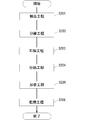
- FIG. 6 is a diagram showing a method for manufacturing a tobacco rod according to the first embodiment.
- FIG. 7 is a diagram showing a detailed structure of the slitter in the cutting section.
- FIG. 8 is a diagram illustrating calendar processing for a tobacco raw material sheet.
- FIG. 1 is a diagram schematically showing the internal structure of the heat-not-burn tobacco according to the first embodiment.
- FIG. 2 is a perspective view showing an example of a tobacco strand.
- FIG. 3 is a
- FIG. 9 is a diagram illustrating a method of producing a tobacco raw material sheet by a papermaking method.
- FIG. 10 is a diagram illustrating a method of producing a tobacco raw material sheet by a casting method.
- FIG. 11 is a diagram showing a tobacco strand according to a modified example.
- FIG. 1 is a diagram schematically showing an internal structure of the heat-not-burn tobacco 1 according to the first embodiment.
- the heat-not-burn tobacco 1 is a type of tobacco article in which the tobacco filler is heated without being burned and the aerosol produced in the tobacco filler is delivered to the user.
- the heat-not-burn tobacco 1 includes a tobacco rod 2 and a mouthpiece portion 3 arranged coaxially.
- Heat-not-burn tobacco 1 has a mouthpiece end 1a that the user inserts into the oral cavity during use, and a tip end 1b at an end opposite to the mouthpiece end 1a.
- the mouthpiece portion 3 has a support portion 4, a cooling portion 5, and a filter portion 6 arranged coaxially, and these members are arranged in order from the tip end side of the mouthpiece portion 3.
- the support portion 4, the cooling portion 5, and the filter portion 6 of the mouthpiece portion 3 are integrally wound by the wrapper 7. Further, the tobacco rod 2 and the mouthpiece portion 3 are integrally connected by being wound up by the tip paper 8.
- a part of the support portion 4, the cooling portion 5, and the filter portion 6 constituting the mouthpiece portion 3 may be integrally wound by a wrapper.
- the one wound integrally with the wrapper and the other parts may be wound with one or more chip papers.
- Reference numeral CL1 shown in FIG. 1 is the central axis of the heat-not-burn tobacco 1.
- the tobacco rod 2 and the mouthpiece portion 3 of the heat-not-burn tobacco 1 are arranged coaxially, and the central axis CL1 can be said to be the central axis of the tobacco rod 2 and the mouthpiece portion 3.
- reference numeral 2a in FIG. 1 is a front end surface of the tobacco rod 2
- reference numeral 2b is a rear end surface of the tobacco rod 2.
- the heat-not-burn tobacco 1 When the heat-not-burn tobacco 1 is used, air is sucked by the user from the tip 1b to the mouthpiece end 1a through the heat-not-burn tobacco 1.
- the tip 1b of the heat-not-burn tobacco 1 can be regarded as the tip or the upstream end of the tobacco rod 2, and the mouthpiece end 1a of the heat-not-burn tobacco 1 can be regarded as the rear end or the downstream end of the mouthpiece portion 3.
- the tobacco rod 2 is arranged at the tip 1b of the heat-not-burn tobacco 1.
- the tobacco rod 2 is a rod-shaped member wrapped with rolling paper 22 so as to cover the side surface of the tobacco filler 21 containing the tobacco raw material and the aerosol-producing base material.
- the tobacco filler 21 has a plurality of strand-shaped tobacco strands 23, which are tobacco raw materials containing an aerosol-forming substrate.
- strand-shaped means an elongated elongated shape extending in a long axis direction orthogonal to the cross-sectional direction, for example, a strip-shaped, strip-shaped, string-shaped, or string-shaped. Shapes such as rods are included.
- the aerosol-forming substrate contained in the tobacco strand 23 of the tobacco filler 21 is a substance that produces an aerosol when the volatile substance that is volatilized and released when the heater is heated is cooled.
- the type of aerosol-producing base material is not particularly limited, and extracts from various natural products can be appropriately selected depending on the intended use. Examples of the aerosol-forming base material include glycerin, propylene glycol, triacetin, 1,3-butanediol, and a mixture thereof.
- the tobacco strand 23 of the tobacco filler 21 may contain a fragrance.
- the type of fragrance is not particularly limited. In this embodiment, an embodiment in which the content of the aerosol-forming base material in the tobacco rod 2 is 10 wt% or more and 25 wt% or less can be exemplified.
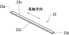
- FIG. 2 is a perspective view showing an example of the tobacco strand 23.
- the tobacco strand 23 has a strip shape (for example, a thin rectangular parallelepiped shape).
- the tobacco strand 23 can also be regarded as a band shape.
- a large number (plurality) of tobacco strands 23 are oriented and arranged on the tobacco filler 21 of the tobacco rod 2 in the present embodiment, and each tobacco strand 23 is arranged in the long axis direction (central axis CL1 direction) of the tobacco rod 2. ) Are aligned so as to extend along.
- the cross section orthogonal to the long axis direction is rectangular.
- Reference numeral 23a shown in FIG. 2 is the front end surface of the tobacco strand 23, and reference numeral 23b is the rear end surface of the tobacco strand 23.
- the front end surface 23a of the tobacco strand 23 is the end surface facing the tip 1b of the heat-not-burn tobacco 1
- the rear end surface 23b of the tobacco strand 23 is the front end surface 23a in the long axis direction (extension direction) of the tobacco strand 23.
- the rear end surface 23b of the tobacco strand 23 is arranged so as to face the front end surface of the support portion 4 arranged at the front end of the mouthpiece portion 3.
- Reference numeral 23c shown in FIG. 2 is a side surface of the tobacco strand 23.
- the tobacco strand 23 shown in FIG. 2 has the same width dimension and thickness dimension from the front end surface 23a to the rear end surface 23b. In other words, the tobacco strand 23 shown in FIG. 2 has a uniform cross-sectional area over the entire length.
- each tobacco strand 23 arranged so as to extend along the long axis direction of the tobacco rod 2 is arranged so that the side surfaces 23c of the tobacco rod 2 face each other.
- each tobacco strand 23 is arranged parallel to each other along the long axis direction of the tobacco rod 2.
- each tobacco strand 23 is stretched and arranged from the front end surface 2a to the rear end surface 2b of the tobacco rod 2.
- Reference numeral 25 shown in FIG. 1 is an aerosol flow path formed by a gap between the tobacco strands 23.
- the aerosol flow path 25 is formed so as to extend along the long axis direction of the tobacco rod 2. Will be done.
- a tobacco raw material sheet obtained by molding a tobacco raw material containing an aerosol-forming base material into a sheet is used as a slitter. It can be obtained by cutting by slitting with or the like.
- the above-mentioned tobacco raw material sheet may be a so-called reconstituted tobacco sheet.
- the reconstituted tobacco sheet is kneaded by adding a binder, a gelling agent, a cross-linking agent, a fragrance, a viscosity regulator, a moisturizing agent, a reinforcing material, etc.
- the homogenized tobacco is, for example, a tobacco material obtained by crushing, grinding and mixing leaf tobacco, dried tobacco leaves, chopped tobacco, swollen tobacco, regenerated tobacco and the like.
- the support portion 4 is a segment located on the front end side of the mouthpiece portion 3 and located at the connection end where the mouthpiece portion 3 is connected to the tobacco rod 2.
- the support portion 4 is located immediately downstream of the tobacco rod 2 and is arranged in contact with the rear end of the tobacco rod 2.
- the support portion 4 may be, for example, a hollow cellulose acetate tube.
- the support portion 4 may be formed by penetrating a center hole in the center of the cross section of the columnar cellulose acetate fiber bundle.
- the support portion 4 may be a paper filter filled with cellulose fibers, a paper tube, or the like. A paper tube having a certain thickness can be effectively functioned as the support portion 4.
- the tobacco filler 21 is moved downstream toward the cooling portion 5 in the heat-not-burn tobacco 1. It is a segment to prevent being pushed.
- the support portion 4 also functions as a spacer for separating the cooling portion 5 of the heat-not-burn tobacco 1 from the tobacco rod 2.
- the cooling unit 5 is located immediately downstream of the support unit 4 and is arranged in contact with the rear end of the support unit 4.
- the volatile substance released from the tobacco rod 2 flows toward the downstream side along the cooling unit 5.
- the volatile substance released from the tobacco rod 2 is cooled by the cooling unit 5 to form an aerosol inhaled by the user.
- the cooling unit 5 is formed of a hollow paper tube having ventilation holes 5a into which external air can be introduced.
- the cooling unit 5 does not have to have the ventilation hole 5a.
- the cooling unit 5 may have a heat absorbing agent arranged so as not to obstruct the flow of volatile substances and aerosols.
- the cooling portion 5 may be formed by a filter material in which a large number of flow paths (through holes) are formed along the longitudinal direction (axial direction) of the mouthpiece portion 3.
- the filter unit 6 is a segment located at the rear end of the mouthpiece unit 3, that is, on the mouthpiece end 1a side.
- the filter unit 6 may be located immediately downstream of the cooling unit 5 and may be arranged in contact with the rear end of the cooling unit 5.
- the filter unit 6 may include, for example, a filter material formed of cellulose acetate fibers formed into a columnar shape.
- the filter unit 6 may be a center hole filter, a paper filter filled with cellulose fibers, or a paper tube containing no filter medium.
- the filter unit 6 may be formed of any of a solid filter material having a filter medium, a center hole filter, a paper filter, and a paper tube containing no filter medium, or is formed by selectively combining a plurality of these. You may.
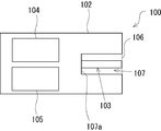
- FIG. 3 is a schematic configuration diagram of a heating device 100 to which the heat-not-burn tobacco 1 according to the first embodiment is applied.
- the heating device 100 has a housing 102 that is a housing for accommodating various components.
- An electric heater 103, a controller (control unit) 104, a power supply 105, and the like are housed in the housing 102.
- the housing 102 has a containment cavity 107 that includes an opening 106 into which the tobacco rod 2 of the heat-not-burn tobacco 1 is inserted.
- the accommodating cavity 107 is a hollow portion having a cylindrical shape for accommodating the tobacco rod 2, and corresponds to a rod accommodating portion to which the tobacco rod 2 can be mounted.
- the present invention can also be provided as a heat-not-burn tobacco product including a heat-not-burn tobacco 1 and a heating device 100 to which the heat-not-burn tobacco 1 is applied.
- an electric heater 103 is provided in the accommodation cavity 107.
- the electric heater 103 shown in FIG. 3 has a cylindrical shape, and projects vertically from the central portion of the bottom portion 107a of the accommodation cavity 107 toward the opening 106 side.
- the shape of the electric heater 103 is not particularly limited.
- the tip side of the electric heater 103 may be sharp.
- the electric heater 103 may have a conical shape and gradually taper from the base end portion connected to the bottom portion 107a in the accommodation cavity 107 toward the tip end portion side.
- the electric heater 103 may have a truncated cone shape (a truncated cone shape) or a blade shape. Further, the electric heater 103 may have other shapes.
- the central axis of the electric heater 103 in this embodiment may be coaxial with the central axis of the accommodating cavity 107.
- the type of the electric heater 103 is not particularly limited, but for example, a steel material having a heating wire (for example, nichrome, iron chromium, iron nickel, etc.) arranged around it, a ceramic heater, a sheathed heater, or the like. Can be used.
- the sheathed heater is a heater in which heat rays are covered with a metal pipe together with a filler.
- the electric heater 103 of the heating device 100 configured as described above is a so-called internal heating type heater. That is, when the tobacco rod 2 is mounted in the accommodation cavity 107 when the heat-not-burn tobacco 1 is used, the electric heater 103 is fitted or inserted into the tobacco filler 21 from the front end surface 2a side of the tobacco rod 2 in the heat-not-burn tobacco 1, and heat is generated. The tobacco filler 21 is heated from the inside by the electric heater 103.
- the controller (control unit) 104 controls the energization from the power supply 105 to the electric heater 103, and the electric heater 103 generates heat, so that the tobacco filler 21 (tobacco strand 23) of the tobacco rod 2 mounted in the accommodation cavity 107 is pressed. Heat.
- the aerosol-forming base material contained in the tobacco filler 21 volatilizes to generate an aerosol
- the aerosol is supplied to the oral cavity of the user who sucks the mouthpiece portion 3.
- each tobacco strand 23 in the tobacco rod 2 is oriented and arranged so as to extend along the long axis direction (central axis CL1 direction) of the tobacco rod 2.
- Each tobacco strand 23 is aligned so as to extend along the long axis direction (central axis CL1 direction) of the tobacco rod 2.
- the aerosol flow path 25, which is a gap between the tobacco strands 23, is formed so as to extend along the long axis direction of the tobacco rod 2. Therefore, the aerosol generated by the volatilization of the aerosol-forming base material contained in the tobacco strand 23 during heating by the electric heater 103 can be guided to the mouthpiece portion 3 through the aerosol flow path 25.
- the aerosol produced by the tobacco rod 2 is less likely to be condensed due to the contact with the tobacco strand 23, and is less likely to be filtered by the tobacco strand 23. Therefore, according to the heat-not-burn tobacco 1 in the present embodiment, the amount of aerosol delivered into the oral cavity of the user can be improved as compared with the conventional case.
- the tobacco strands 23 in the tobacco rod 2 are aligned along the long axis direction (central axis CL1 direction) of the tobacco rod 2, as in the conventional case.
- the operation of inserting or inserting the electric heater 103 from the tip 1b side of the tobacco rod 2 becomes easier.
- the electric heater 103 can be easily inserted or inserted into the tobacco rod 2, and the heated tobacco 1 can be provided with excellent usability for the user.
- the delivery amount of the aerosol is excellent, and the electric heater 103 can be smoothly inserted into the tobacco filler 21.
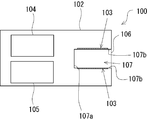
- the heating device applied to the heat-not-burn tobacco 1 in the present embodiment may include an external heating type heater as shown in FIG. 4 instead of the internal heating type as shown in FIG.
- the heating device 100 shown in FIG. 4 has the same structure as the heating device 100 shown in FIG. 3, except that the electric heater 103 is an external heating type.
- the electric heater 103 shown in FIG. 4 is an annular external heating type heater formed along the cavity side peripheral wall 107b in the accommodation cavity 107.
- the electric heater 103 shown in FIG. 4 may be arranged along the cavity side peripheral wall 107A so as to be flush with the cavity side peripheral wall 107b, for example.
- the volume filling rate of the tobacco strand 23 referred to here is the ratio of the total volume of all the tobacco strands 23 contained in the tobacco rod 2 to the volume of the tobacco rod 2. If the volume filling rate of the tobacco strand 23 is excessively high, there is a concern that the ventilation resistance of the tobacco rod 2 (tobacco filling material 21) becomes excessively high. As a result, the aerosol generated by the tobacco rod 2 at the time of use is filtered (captured) by the tobacco strand 23 in the tobacco rod 2 before being introduced into the mouthpiece portion 3, and the delivery amount of the aerosol is reduced. There is concern that it will end up.
- the volume filling rate of the tobacco strand 23 is excessively low, there is a concern that the heat transfer efficiency to the tobacco strand 23 will decrease during heating by the electric heater 103, and the amount of aerosol delivered will decrease.
- the internal heating type electric heater 103 shown in FIG. 3 the contact between the electric heater 103 and the tobacco strand 23 becomes insufficient with the electric heater 103 inserted in the tobacco rod 2, and the tobacco strand There is a risk that the heating of 23 will be insufficient.
- the present inventors have obtained the finding that it is preferable that the volume filling rate of the tobacco strand 23 occupying the tobacco rod 2 is 50 vol% or more and 80 vol% or less as a result of diligent studies. As a result, it is possible to suppress the decrease in the heat transfer efficiency from the electric heater 103 to the tobacco strand 23 while suppressing the aeration resistance of the tobacco rod 2 (tobacco filler 21) from becoming excessively high. As a result, it is possible to prevent the amount of aerosol delivered from being reduced during use.
- the volume filling rate of the tobacco strand 23 is lower than 50 vol%, the heat transfer efficiency from the electric heater 103 to the tobacco strand 23 is lowered, and the manufacturing suitability of the tobacco rod 2 may be lowered. Further, if the volume filling rate of the tobacco strand 23 exceeds 80 vol%, it becomes difficult to insert the electric heater 103 into the tobacco rod 2, the ventilation resistance tends to increase, and the aerosol traps in the middle. It may be captured) and the delivery efficiency of the aerosol may decrease.
- the volume filling rate of the tobacco strand 23 occupying the tobacco rod 2 is preferably in the range of 50 vol% or more and 80 vol% or less.
- the preferable range of the volume filling rate of the tobacco strand 23 occupying the tobacco rod 2 is the difference in the heating method of the electric heater 103 of the heating device 100 to which the heating type tobacco 1 is applied (internal heating type heater, external heating type heater). ) Depends on. Further, when the electric heater 103 is an internal heating type, it depends on whether or not the electric heater 103 is inserted into the tobacco rod 2 (the state in which the tobacco rod 2 is attached to the heating device 100). The preferred range of volume filling of the tobacco strand 23 is different.
- the volume filling rate of the tobacco strand 23 occupying the tobacco rod 2 is 60 vol% or more and 80 vol% or less. Is preferable.
- the volume filling rate of the tobacco strand 23 occupying the tobacco rod 2 is 50 vol% or more and 75 vol% or less. Is preferable, and 60 vol% is more preferable.
- the volume filling rate up to the above refers to a preferable range of the volume filling rate of the tobacco strand 23 before mounting the tobacco rod 2 in the accommodation cavity 107 of the heating device 100.
- the preferable range (50 vol% or more and 75 vol% or less) of the volume filling rate of the tobacco strand 23 when the electric heater 103 of the heating device 100 to which the heat-not-burn tobacco 1 is applied is an internal heating heater is determined. It is lower than the preferable range (60 vol% or more and 80 vol% or less) of the volume filling rate of the tobacco strand 23 when the electric heater 103 is an external heating type heater.
- the electric heater 103 of the heating device 100 to which the heating type tobacco 1 is applied is an internal heating type heater
- the state where the tobacco rod 2 is attached to the accommodating cavity 107, that is, the internal heating type heater is attached to the tobacco rod 2.
- the volume filling rate of the tobacco strand 23 in the inserted state is preferably 60 vol% or more and 80 vol% or less.
- the volume filling rate of the tobacco strand 23 with the tobacco rod 2 mounted in the accommodation cavity 107 is calculated by subtracting the volume occupied by the electric heater 103 from the volume of the tobacco rod 2. It is the ratio of the total volume of the tobacco strand 23 to the volume.
- the width dimension of the cross section of the tobacco strand 23 is 0.4 mm or more and 3 mm. It is preferable that the thickness dimension of the cross section of the tobacco strand 23 is 0.02 mm or more and 1.3 mm or less. As an example, the length dimension of the tobacco strand 23 along the long axis direction is 10 mm or more and 50 mm or less.
- the tobacco strand 23 in the present embodiment has a uniform cross-sectional area over the entire length, the amount of aerosol produced in the long axis direction of the tobacco strand 23 when heated by the electric heater 103 is increased. Variation is less likely to occur.
- each dimension of the tobacco rod 2 is not particularly limited, but the length of the tobacco rod 2 in the major axis direction is 10 mm or more and 50 mm or less, and the diameter of the cross section orthogonal to the major axis direction of the tobacco rod 2.
- the maximum diameter of the electric heater 103 is 2.5 mm or more and 3.2 mm or less can be exemplified.
- the ratio of the maximum diameter of the electric heater 103 to the diameter of the cross section of the tobacco rod 2 is 0.3 or more and 0.6 or less can be exemplified.
- the length of the tobacco strand 23 arranged on the tobacco rod 2 in the major axis direction is set to have a dimension substantially equal to the length of the tobacco rod 2 in the major axis direction.
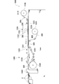
- FIG. 5 is a diagram showing a manufacturing apparatus (hereinafter, referred to as “rod manufacturing apparatus”) 1000 for the tobacco rod 2 according to the first embodiment.
- FIG. 6 is a diagram showing a method of manufacturing a tobacco rod 2 in the heat-not-burn tobacco 1.
- the rod manufacturing apparatus 1000 includes a first bobbin 1100, a cutting section 1200, a molding section 1300, a cutting section 1400, etc., in which the tobacco raw material sheet 200 is wound into a roll.
- the tobacco raw material sheet 200 wound around the first bobbin 1100 is a sheet material obtained by molding a tobacco raw material containing an aerosol-forming base material into a sheet shape. Examples of the tobacco raw material include tobacco chopped tobacco, tobacco granules, and reconstituted tobacco material. In the present embodiment, an example in which the reconstituted tobacco is molded into a sheet and used as the tobacco raw material sheet 200 will be described.
- the tobacco raw material sheet 200 is cut in the cutting section 1200 and cut in the cutting section 1400 to become the tobacco strand 23 of the tobacco rod 2 described above.
- the first bobbin 1100 is rotatably held by the bobbin holder 1110.
- the tobacco raw material sheet 200 wound around the first bobbin 1100 is continuously unwound by a delivery roller arranged at an appropriate position, and is fed along a transport path P.
- the cutting section 1200 in the rod manufacturing apparatus 1000 is arranged in the middle of the transport path P.
- the front is defined as "downstream” and the rear is defined as “upstream” along the flow direction of the transport path P.
- the molding section 1300 is arranged on the downstream side (rear stage) of the cutting section 1200, and the cutting section 1400 is arranged on the further downstream side (rear stage) of the molding section 1300.
- the direction along the transport path P is called the "sheet length direction (long direction)"
- the direction orthogonal to the transport path P is called the "sheet width direction”.
- the direction orthogonal to the transport path P is referred to as the "device width direction”.
- Reference numeral 1500 shown in FIG. 5 is a transport tray extending along the transport path P. The sheet-shaped tobacco raw material sheet 200 is introduced into the cutting section 1200 while traveling on the transport tray 1500 along the transport path P.
- the cutting section 1200 is a unit that continuously cuts the tobacco raw material sheet 200 into a plurality of strand-shaped tobacco strand continuums 300 along the transport path.
- FIG. 7 is a diagram showing a detailed structure of the slitter 1210 in the cutting section 1200, showing a state in which the slitter 1210 is viewed from above.
- the slitter 1210 has a plurality of circular cutter discs 1220. The centers of the plurality of circular cutter discs 1220 are connected to each other by a rotating shaft member 1230.
- the rotary shaft member 1230 is rotatably supported on the base of the rod manufacturing apparatus 1000, and each cutter disc 1220 can be integrally rotated around the rotary shaft member 1230.
- the rotary shaft member 1230 in the slitter 1210 extends in the horizontal direction along the direction orthogonal to the transport path P in the rod manufacturing apparatus 1000, that is, the apparatus width direction. Then, as shown in FIG. 7, each cutter disk 1220 in the slitter 1210 is arranged in a direction orthogonal to the rotation shaft member 1230 and parallel to the transport path P. Further, the cutter disks 1220 in the slitter 1210 are arranged at regular intervals along a direction orthogonal to the transport path P (device width direction).
- the tobacco raw material sheet 200 obtained by molding the tobacco raw material containing the aerosol-producing base material into a sheet shape is transported from the first bobbin 1100 along the transport path P.
- the tobacco raw material sheet 200 is continuously cut into a plurality of strand-shaped tobacco strand continuums 300 along the transport path P. That is, as the tobacco raw material sheet 200 passes through the cutting section 1200 (each cutter disk 1220 arranged in parallel with the transport path P) along the transport path P, the tobacco raw material sheet 200 is continuously formed by each cutter disc 1220. It is cut into a plurality of tobacco strand continuums 300.
- the tobacco raw material sheet 200 is cut into a plurality of tobacco strand continuums 300 having a constant width.
- the tobacco strand continuum 300 is a long tobacco material that extends along the transport path P.
- the slitter 1210 only needs to be able to continuously cut the tobacco raw material sheet 200 into a plurality of strand-shaped tobacco strand continuums 300 along the transport path P, and the tobacco raw material sheet is made of a member different from each cutter disk 1220. You may cut 200.
- the slitter 1210 may have a roll cutter having comb blades arranged at regular intervals along the device width direction.
- the plurality of tobacco strand continuums 300 cut from the tobacco raw material sheet 200 in the cutting section 1200 are sent to the subsequent molding section 1300 along the transport path P in a state of being aligned in the width direction of the transport tray 1500.
- the molding section 1300 has a second bobbin 1310 in which a long wrapping paper web 400 is wound into a roll.
- the wrapping paper web 400 is a long web material that serves as a wrapping paper 22 for the tobacco rod 2.
- the molding section 1300 further includes a converging portion 1320, a packaging mechanism 1330, an adhesive coating device 1340, and the like.
- the converging portion 1320 is arranged near the entrance in the forming section 1300, and converges a plurality of tobacco strand continuums 300 sent from the upstream side to form a cylindrical shape (that is, a rod shape).
- the converging portion 1320 may be, for example, a combination form of a tongue member and a horn, a converging funnel form, a transport jet form, or the like.
- the packaging mechanism 1330 in the molding section 1300 is provided after the converging portion 1320.
- the packaging mechanism 1330 has an endless crabcha belt 1350.
- the crabcha belt 1350 is composed of a woven material, a woven web, or the like, and travels at a constant speed in the direction of the arrow in the drawing by the drive drum 1360.
- the long wrapping web 400 unwound from the second bobbin 1310 is continuously fed onto the crab belt 1350 in the forming section 1300.
- the plurality of tobacco strand continuums 300 shaped like rods at the converging portion 1320 in the forming section 1300 are superposed on the long wrapping paper web 400 on the ganicha belt 1350.
- the plurality of tobacco strand continuums 300 stacked on the long wrapping paper web 400 on the crabcha belt 1350 in this way are aligned in a rod shape in the process of being transported along the transport path P by the crabcha belt 1350.
- a wrapping paper web 400 is wrapped around the outer periphery of the tobacco strand continuum 300, and the plurality of tobacco strand continuums 300 are wrapped by the wrapping paper web 400.
- an adhesive for example, hot melt adhesive, CMC (carboxymethyl cellulose), PVA (polyvinyl alcohol), EVA (ethylene acetic acid) is used in the adhesive coating device 1340. Vinyl copolymer resin) etc. is applied. As a result, a rod-shaped and long tobacco rod continuum 500 is formed (molding step, S102 in FIG. 6).
- the fragrance and the aerosol-forming base material is added to the plurality of tobacco strand continuums 300 obtained in the cutting step (cutting section 1200).
- the addition step may be further included.
- a fragrance and an aerosol are generated for the plurality of tobacco strand continuums 300.
- At least one of the substrates may be added.
- the method for adding the perfume or aerosol-forming base material to the plurality of tobacco strand continuums 300 is not particularly limited, but even if the perfume or aerosol-forming base material is discharged from the addition nozzle to the tobacco strand continuum 300. Good.
- the addition nozzle for adding the fragrance and the addition nozzle for adding the aerosol-forming base material may be provided separately.
- the fragrance, menthol or the like can be exemplified, but other fragrances may be added.
- the nozzle may be placed in place in the molding section 1300. Further, the addition nozzle for adding the fragrance or the aerosol-forming base material to the tobacco strand continuum 300 may be provided at any portion between the cutting section 1200 and the molding section 1300 in the transport path P.
- the tobacco rod continuum 500 obtained in the molding section 1300 is sent to the cutting section 1400 located at the subsequent stage of the molding section 1300.
- the cutting section 1400 has a cutting means such as a rotary cutter and a knife, and the long tobacco rod continuum 500 is cut to a constant length in the cutting section 1400. That is, in the cutting step (S103 of FIG. 6), the tobacco rod continuum 500 obtained in the molding step (S102 of FIG. 6) is sequentially cut into individual tobacco rods, whereby the tobacco rod of the heat-not-burn tobacco 1 is cut. Is obtained.
- the plurality of tobacco strand continuums 300 cut from the tobacco raw material sheet 200 in the cutting section 1200 are transported in the transport path P until they are cut in the cutting section 1400 in the axial direction. They are connected along the direction.
- the tobacco rod 2 according to the heat-not-burn tobacco 1 can be suitably produced.
- the tobacco raw material sheet 200 is continuously cut into a plurality of tobacco strand continuums 300 in the cutting section 1200, and then the tobacco strands are cut in the cutting section 1400.
- the tobacco strand continuum 300 aligned along the transport path P is wrapped with a wrapping paper (wrapping paper web 400) in the molding section 1300 and molded into a long tobacco rod continuum 500. It is characterized by that.
- the plurality of tobacco strands 23 can be arranged and arranged so that the plurality of tobacco strands 23 extend along the axial direction of the tobacco rod 2. That is, it is possible to easily manufacture a tobacco rod 2 in which a plurality of tobacco strands 23 are arranged in parallel with each other along the long axis direction of the tobacco rod 2.
- the tobacco strand 23 having a desired thickness can be obtained. Further, by adjusting the spacing between the cutter discs 1220 in the slitter 1210 arranged in the cutting section 1200, the tobacco strand 23 having a desired width can be obtained. Further, in the present embodiment, in the cutting section 1200 (cutting step), when the tobacco raw material sheet 200 is cut, it is cut into a plurality of tobacco strand continuums 300 having a certain width, so that the tobacco rod 2 is arranged. The cross-sectional area (width dimension) of each tobacco strand 23 to be produced can be made uniform. As a result, when the heat-not-burn tobacco 1 is used, it becomes easy to prevent the occurrence of non-uniform delivery characteristics of the aerosol in the cross section of the tobacco rod 2, and the aerosol can be stably supplied to the user. ..
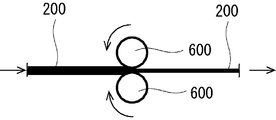
- the tobacco raw material sheet 200 used for manufacturing the tobacco rod 2 is subjected to a calendar process in advance to increase the density of the tobacco raw material sheet 200. It may include a step and a winding step of winding the tobacco raw material sheet 200 after the calendar processing is performed on the first bobbin 1100.
- FIG. 8 is a diagram illustrating calendar processing for the tobacco raw material sheet 200.
- the calendar processing is performed by pressing the tobacco raw material sheet 200 by continuously passing the tobacco raw material sheet 200 between the pair of press rollers 600, 600 as shown in FIG. 7, for example.
- the tobacco raw material sheet 200 becomes dense and its density can be increased.
- the weight of the tobacco strand 23 is increased while suppressing the volume filling rate of the tobacco strand 23 contained in the manufactured tobacco rod 2 from becoming excessively high and the aeration resistance of the tobacco rod 2 from becoming excessively high. Can be made to.
- the amount of aerosol delivered to the tobacco rod 2 can be further increased.
- the tobacco raw material sheet 200 after being subjected to the calendar processing as described above is wound on the first bobbin 1100 in the winding process.
- the tobacco raw material sheet 200 wound around the first bobbin 1100 is continuously drawn out along the transport path P as described with reference to FIGS. 5 and 6, and is used for manufacturing the tobacco rod 2.
- an appropriate method such as a papermaking method (papermaking method), a casting method (slurry method), a rolling method, or an extrusion method can be adopted as described above.
- FIG. 8 is a diagram illustrating a method of manufacturing a tobacco raw material sheet 200 by a papermaking method (papermaking method).
- a tobacco raw material containing tobacco metatarsal bones, tobacco lamina, tobacco chopped, tobacco fine powder, and the like is extracted with water (extraction step).
- extraction step for example, 10 times the amount of water is added to the tobacco raw material, and the mixture is heated for a predetermined temperature and time with stirring to obtain a mixture.
- step S202 the mixture obtained in the extraction step is squeezed using, for example, a screw press dehydrator or the like, and separated into an aqueous tobacco extract (liquid) and an insoluble tobacco residue (solid) (separation step).
- step S203 water and pulp (cellulose fibers) are added to the insoluble tobacco residue obtained in the separation step, and then, for example, the insoluble tobacco residue is beaten with a refiner to adjust the fiber length and fluff the fibers. It becomes fibrous (beating process).
- step S204 the insoluble tobacco residue and pulp fiberized in the beating step are made into a sheet by a paper machine and dried to obtain a base sheet (paper making step).
- step S205 a concentrated solution of the aqueous tobacco extract obtained in the above separation step and an additive solution containing an aerosol-forming base material such as glycerin and propylene glycol are added to the base sheet (fragrance step). ).
- the concentrated solution of the aqueous tobacco extract added to the base sheet in the incense step can be obtained, for example, by concentrating the aqueous tobacco extract with an evaporator.
- step S206 the flavored base sheet obtained in the flavoring step is dried (drying step).
- the tobacco raw material sheet 200 can be manufactured by the papermaking method (papermaking method).
- the above manufacturing method is an example, and steps can be added, omitted, or replaced as appropriate.
- the content of the aerosol-forming base material is 15.0 wt%
- the content of the tobacco raw material is 79.05 wt%
- the pulp content As an example, there is an example in which the value is 5.95 wt%, but it is needless to say that the ratio is not limited to this.
- the content of the aerosol-producing base material is preferably 10 wt% or more and 25 wt% or less.
- FIG. 9 is a diagram illustrating a method of manufacturing a tobacco raw material sheet 200 by a casting method (slurry method).
- a tobacco raw material containing tobacco core bone, tobacco lamina, tobacco chopped, tobacco fine powder, etc. is finely pulverized, and then a small amount of binder (binder) and reinforcing agent (pulp) are used.
- a slurry is obtained by mixing a predetermined amount of an aerosol-forming substrate (glycerin, propylene glycol, etc.) and water, for example, in a stirring tank (slurry acquisition step).
- the binder (binder) include guar gum, xanthan gum, CMC (methylol fiber) and the like.
- step S302 the slurry obtained in the slurry acquisition step is cast (stretched) into a sheet on, for example, a steel belt (support) to obtain a slurry web (casting step).
- step S303 the sheet-shaped slurry web stretched into a sheet-like shape is dried (drying step).
- the tobacco raw material sheet 200 is obtained.
- the content of the aerosol-forming base material for example, glycerin
- the content of the tobacco raw material is 76.0 wt%
- pulp As an example, the content of the binder is 6.0 wt% and the binder content is 3.0 wt%, but the present invention is not limited to this.
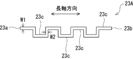
- FIG. 11 is a diagram showing a tobacco strand 23A according to a modified example.
- the tobacco strand 23A shown in FIG. 11 has a meandering shape (zigza shape).
- the tobacco strands 23A extending in a meandering shape in this way are arranged and arranged in the tobacco rod 2 so that their long axis direction (stretching direction) extends along the long axis direction of the tobacco rod 2.
- the tobacco strand 23A having such a serpentine shape (zigza shape) is a tobacco rod 2 even if the tobacco strand 23A is pushed by the electric heater 103 when the electric heater 103 in the heating device 100 is inserted into the tobacco rod 2. It is possible to prevent the misalignment of the tobacco strand 23A in the major axis direction from occurring. As a result, when the electric heater 103 is inserted into the tobacco rod 2, the tobacco strand 23A can be suitably suppressed from coming out from the tobacco rod 2.
- the tobacco strand 23A shown in FIG. 11 is relatively obstructed by the flow path of the aerosol generated by the tobacco rod 2 due to heating by the electric heater 103, as compared with the linear tobacco strand 23 shown in FIGS. 1 and 2.
- the amount of aerosol delivered is improved compared to the conventional case where the tobacco raw material is randomly oriented, because the aerosol produced by the tobacco rod 2 is relatively less likely to condense and filter. Can be made to.
- the width of the tobacco strand 23A is preferably uniform from the front end surface 23a to the rear end surface 23b. That is, as shown in FIG. 11, it is preferable that the width dimension W1 of the portion parallel to the long axis direction of the tobacco strand 23A and the width dimension W2 of the portion extending in the direction orthogonal to the semi-axis direction are equal. By doing so, it is possible to make the cross-sectional area of the tobacco strand 23A uniform over the entire length.
- the tobacco strand 23A shown in FIG. 11 has a meandering shape (zigza shape), it may have a corrugated shape or another shape.
Abstract
Priority Applications (7)
| Application Number | Priority Date | Filing Date | Title |
|---|---|---|---|
| EP19920753.1A EP3949769A4 (fr) | 2019-03-28 | 2019-03-28 | Tabac à chauffer, produit à base de tabac à chauffer, et procédé et dispositif de production de tige de tabac pour tabac à chauffer |
| CN201980094918.8A CN113645858B (zh) | 2019-03-28 | 2019-03-28 | 加热式香烟、加热式香烟制品、加热式香烟中的烟杆的制造方法以及制造装置 |
| PCT/JP2019/013706 WO2020194688A1 (fr) | 2019-03-28 | 2019-03-28 | Tabac à chauffer, produit à base de tabac à chauffer, et procédé et dispositif de production de tige de tabac pour tabac à chauffer |
| KR1020217033490A KR20210139392A (ko) | 2019-03-28 | 2019-03-28 | 가열식 담배, 가열식 담배 제품, 가열식 담배에서의 담배 로드의 제조 방법 및 제조 장치 |
| JP2021508618A JP7238096B2 (ja) | 2019-03-28 | 2019-03-28 | 加熱式たばこ、加熱式たばこ製品、加熱式たばこにおけるたばこロッドの製造方法および製造装置 |
| JP2023026181A JP7454721B2 (ja) | 2019-03-28 | 2023-02-22 | 加熱式たばこ、加熱式たばこ製品 |
| JP2024037226A JP2024053115A (ja) | 2019-03-28 | 2024-03-11 | 加熱式たばこ、加熱式たばこ製品 |
Applications Claiming Priority (1)
| Application Number | Priority Date | Filing Date | Title |
|---|---|---|---|
| PCT/JP2019/013706 WO2020194688A1 (fr) | 2019-03-28 | 2019-03-28 | Tabac à chauffer, produit à base de tabac à chauffer, et procédé et dispositif de production de tige de tabac pour tabac à chauffer |
Publications (1)
| Publication Number | Publication Date |
|---|---|
| WO2020194688A1 true WO2020194688A1 (fr) | 2020-10-01 |
Family
ID=72611254
Family Applications (1)
| Application Number | Title | Priority Date | Filing Date |
|---|---|---|---|
| PCT/JP2019/013706 WO2020194688A1 (fr) | 2019-03-28 | 2019-03-28 | Tabac à chauffer, produit à base de tabac à chauffer, et procédé et dispositif de production de tige de tabac pour tabac à chauffer |
Country Status (5)
| Country | Link |
|---|---|
| EP (1) | EP3949769A4 (fr) |
| JP (3) | JP7238096B2 (fr) |
| KR (1) | KR20210139392A (fr) |
| CN (1) | CN113645858B (fr) |
| WO (1) | WO2020194688A1 (fr) |
Cited By (2)
| Publication number | Priority date | Publication date | Assignee | Title |
|---|---|---|---|---|
| US20220030936A1 (en) * | 2019-04-18 | 2022-02-03 | Japan Tobacco Inc. | Heated tobacco product |
| KR102659901B1 (ko) * | 2021-07-20 | 2024-04-24 | 이건 | 슬라이버를 이용한 담배 필터의 제조 방법 및 이에 따라 제조된 친환경 담배 필터 |
Citations (10)
| Publication number | Priority date | Publication date | Assignee | Title |
|---|---|---|---|---|
| US2039298A (en) * | 1932-12-03 | 1936-05-05 | Davidson Glenn | Cigarette mouthpiece |
| JPS5920744B2 (ja) | 1974-03-08 | 1984-05-15 | ブリテイツシユ スチ−ル コ−ポレ−シヨン | 電磁用珪素鋼の製造方法ならびに該珪素鋼 |
| JPS60451B2 (ja) | 1977-11-17 | 1985-01-08 | ホリングスワ−ス(ユ−、ケイ)リミテッド | オ−プンエンド精紡機の停止方法とその装置 |
| JPS6017546B2 (ja) | 1982-01-14 | 1985-05-04 | 航空宇宙技術研究所長 | 燃料タンク火災の消火方法 |
| JPS62272962A (ja) | 1986-05-14 | 1987-11-27 | ア−ル・ジエイ・レノルズ・タバコ・カンパニ− | シ−ト状材料から得られたストランドを包含した巻きたばこロツド及びフイルタロツド及び該ロツドを製造するための方法及び装置 |
| JP2013519384A (ja) * | 2010-02-19 | 2013-05-30 | フィリップ・モーリス・プロダクツ・ソシエテ・アノニム | 喫煙物品のためのエアロゾル発生基体 |
| JP2016536008A (ja) * | 2013-10-14 | 2016-11-24 | フィリップ・モーリス・プロダクツ・ソシエテ・アノニム | 改良型ロッドを含む加熱式エアロゾル発生物品 |
| JP6371928B1 (ja) * | 2018-02-23 | 2018-08-08 | 株式会社 東亜産業 | 電子タバコ用充填物およびそれを用いた電子タバコカートリッジ |
| WO2019030276A1 (fr) * | 2017-08-09 | 2019-02-14 | Philip Morris Products S.A. | Article générateur d'aérosol muni d'une tige à plusieurs éléments allongés longitudinaux d'un matériau autre que le tabac |
| WO2019057796A1 (fr) * | 2017-09-22 | 2019-03-28 | British American Tobacco (Investments) Limited | Segment de tige de matériau de génération d'aérosol |
Family Cites Families (9)
| Publication number | Priority date | Publication date | Assignee | Title |
|---|---|---|---|---|
| JPS60451A (ja) | 1983-06-16 | 1985-01-05 | Minolta Camera Co Ltd | 電子写真用感光体 |
| US5025814A (en) * | 1987-05-12 | 1991-06-25 | R. J. Reynolds Tobacco Company | Cigarette filters containing strands of tobacco-containing materials |
| PT3033950T (pt) | 2011-05-31 | 2018-11-08 | Philip Morris Products Sa | Hastes para utilização em artigos para fumar |
| AR089602A1 (es) | 2011-12-30 | 2014-09-03 | Philip Morris Products Sa | Articulo generador de aerosoles para usar con un dispositivo generador de aerosoles |
| BR112015020047B1 (pt) * | 2013-03-15 | 2021-06-15 | Philip Morris Products S.A. | Artigo fumígeno com uma extremidade de bocal e uma extremidade distal |
| BR112016011257B1 (pt) | 2013-12-05 | 2022-03-03 | Philip Morris Products S.A. | Artigo gerador de aerossol aquecido para uso com um dispositivo gerador de aerossol, sistema gerador de aerossol aquecido e método de fumar o artigo gerador de aerossol aquecido |
| EA039036B1 (ru) * | 2015-04-06 | 2021-11-24 | Джапан Тобакко Инк. | Ингалятор аромата |
| TW201703660A (zh) * | 2015-06-23 | 2017-02-01 | 菲利浦莫里斯製品股份有限公司 | 氣溶膠產生物件及製造氣溶膠產生物件之方法 |
| JP6371927B1 (ja) * | 2018-02-23 | 2018-08-08 | 株式会社 東亜産業 | 非タバコ植物組成物の製造方法、電子タバコ用充填物の製造方法、電子タバコ用充填物及びそれを用いた電子タバコカートリッジ |
-
2019
- 2019-03-28 WO PCT/JP2019/013706 patent/WO2020194688A1/fr unknown
- 2019-03-28 EP EP19920753.1A patent/EP3949769A4/fr active Pending
- 2019-03-28 JP JP2021508618A patent/JP7238096B2/ja active Active
- 2019-03-28 KR KR1020217033490A patent/KR20210139392A/ko not_active Application Discontinuation
- 2019-03-28 CN CN201980094918.8A patent/CN113645858B/zh active Active
-
2023
- 2023-02-22 JP JP2023026181A patent/JP7454721B2/ja active Active
-
2024
- 2024-03-11 JP JP2024037226A patent/JP2024053115A/ja active Pending
Patent Citations (10)
| Publication number | Priority date | Publication date | Assignee | Title |
|---|---|---|---|---|
| US2039298A (en) * | 1932-12-03 | 1936-05-05 | Davidson Glenn | Cigarette mouthpiece |
| JPS5920744B2 (ja) | 1974-03-08 | 1984-05-15 | ブリテイツシユ スチ−ル コ−ポレ−シヨン | 電磁用珪素鋼の製造方法ならびに該珪素鋼 |
| JPS60451B2 (ja) | 1977-11-17 | 1985-01-08 | ホリングスワ−ス(ユ−、ケイ)リミテッド | オ−プンエンド精紡機の停止方法とその装置 |
| JPS6017546B2 (ja) | 1982-01-14 | 1985-05-04 | 航空宇宙技術研究所長 | 燃料タンク火災の消火方法 |
| JPS62272962A (ja) | 1986-05-14 | 1987-11-27 | ア−ル・ジエイ・レノルズ・タバコ・カンパニ− | シ−ト状材料から得られたストランドを包含した巻きたばこロツド及びフイルタロツド及び該ロツドを製造するための方法及び装置 |
| JP2013519384A (ja) * | 2010-02-19 | 2013-05-30 | フィリップ・モーリス・プロダクツ・ソシエテ・アノニム | 喫煙物品のためのエアロゾル発生基体 |
| JP2016536008A (ja) * | 2013-10-14 | 2016-11-24 | フィリップ・モーリス・プロダクツ・ソシエテ・アノニム | 改良型ロッドを含む加熱式エアロゾル発生物品 |
| WO2019030276A1 (fr) * | 2017-08-09 | 2019-02-14 | Philip Morris Products S.A. | Article générateur d'aérosol muni d'une tige à plusieurs éléments allongés longitudinaux d'un matériau autre que le tabac |
| WO2019057796A1 (fr) * | 2017-09-22 | 2019-03-28 | British American Tobacco (Investments) Limited | Segment de tige de matériau de génération d'aérosol |
| JP6371928B1 (ja) * | 2018-02-23 | 2018-08-08 | 株式会社 東亜産業 | 電子タバコ用充填物およびそれを用いた電子タバコカートリッジ |
Cited By (2)
| Publication number | Priority date | Publication date | Assignee | Title |
|---|---|---|---|---|
| US20220030936A1 (en) * | 2019-04-18 | 2022-02-03 | Japan Tobacco Inc. | Heated tobacco product |
| KR102659901B1 (ko) * | 2021-07-20 | 2024-04-24 | 이건 | 슬라이버를 이용한 담배 필터의 제조 방법 및 이에 따라 제조된 친환경 담배 필터 |
Also Published As
| Publication number | Publication date |
|---|---|
| JP2024053115A (ja) | 2024-04-12 |
| JP7238096B2 (ja) | 2023-03-13 |
| EP3949769A4 (fr) | 2022-11-16 |
| EP3949769A1 (fr) | 2022-02-09 |
| JP2023054252A (ja) | 2023-04-13 |
| JPWO2020194688A1 (ja) | 2021-11-04 |
| CN113645858A (zh) | 2021-11-12 |
| JP7454721B2 (ja) | 2024-03-22 |
| CN113645858B (zh) | 2023-08-25 |
| KR20210139392A (ko) | 2021-11-22 |
Similar Documents
| Publication | Publication Date | Title |
|---|---|---|
| TWI605764B (zh) | 混合桿、形成此種混合桿的方法、氣溶膠產生物品、氣溶膠產生基體及包含電操作氣溶膠產生設備及氣溶膠產生物品的系統 | |
| RU2634858C1 (ru) | Ароматизированные стержни для использования в аэрозоль-генерирующих изделиях | |
| US10568357B2 (en) | Thermally conducting rods for use in aerosol-generating articles | |
| US10010110B2 (en) | Electrically operated aerosol generating system | |
| JP7056997B2 (ja) | エアロゾル形成ロッドの製造方法及び製造装置 | |
| KR102626546B1 (ko) | 담배 재료의 다수의 길이방향 세장형 요소를 갖춘 로드를 갖는 에어로졸 발생 물품 | |
| JP2022522157A (ja) | 誘導加熱式エアロゾル形成ロッドおよびそのようなロッドの製造で使用するための成形装置 | |
| JP2022521617A (ja) | 誘導加熱式エアロゾル形成ロッドおよびそのようなロッドの製造における使用のための成形装置 | |
| JP2022522156A (ja) | 誘導加熱式エアロゾル形成ロッドおよびそのようなロッドの製造で使用するための成形装置 | |
| JP2024053115A (ja) | 加熱式たばこ、加熱式たばこ製品 | |
| RU2783381C1 (ru) | Способ и устройство для получения табачного стержня из табака для нагревания | |
| TW202034796A (zh) | 加熱式香菸、加熱式香菸製品、加熱式香菸中的煙草桿的製造方法及製造裝置 |
Legal Events
| Date | Code | Title | Description |
|---|---|---|---|
| 121 | Ep: the epo has been informed by wipo that ep was designated in this application |
Ref document number: 19920753 Country of ref document: EP Kind code of ref document: A1 |
|
| ENP | Entry into the national phase |
Ref document number: 2021508618 Country of ref document: JP Kind code of ref document: A |
|
| NENP | Non-entry into the national phase |
Ref country code: DE |
|
| ENP | Entry into the national phase |
Ref document number: 20217033490 Country of ref document: KR Kind code of ref document: A |
|
| ENP | Entry into the national phase |
Ref document number: 2019920753 Country of ref document: EP Effective date: 20211028 |