WO2020194437A1 - ブラインド用スラット及びその製造方法並びにブラインド - Google Patents
ブラインド用スラット及びその製造方法並びにブラインド Download PDFInfo
- Publication number
- WO2020194437A1 WO2020194437A1 PCT/JP2019/012451 JP2019012451W WO2020194437A1 WO 2020194437 A1 WO2020194437 A1 WO 2020194437A1 JP 2019012451 W JP2019012451 W JP 2019012451W WO 2020194437 A1 WO2020194437 A1 WO 2020194437A1
- Authority
- WO
- WIPO (PCT)
- Prior art keywords
- blind
- slats
- slat
- diffusion type
- light
- Prior art date
- Legal status (The legal status is an assumption and is not a legal conclusion. Google has not performed a legal analysis and makes no representation as to the accuracy of the status listed.)
- Ceased
Links
Images








Classifications
-
- E—FIXED CONSTRUCTIONS
- E06—DOORS, WINDOWS, SHUTTERS, OR ROLLER BLINDS IN GENERAL; LADDERS
- E06B—FIXED OR MOVABLE CLOSURES FOR OPENINGS IN BUILDINGS, VEHICLES, FENCES OR LIKE ENCLOSURES IN GENERAL, e.g. DOORS, WINDOWS, BLINDS, GATES
- E06B9/00—Screening or protective devices for wall or similar openings, with or without operating or securing mechanisms; Closures of similar construction
- E06B9/24—Screens or other constructions affording protection against light, especially against sunshine; Similar screens for privacy or appearance; Slat blinds
- E06B9/26—Lamellar or like blinds, e.g. venetian blinds
- E06B9/266—Devices or accessories for making or mounting lamellar blinds or parts thereof
-
- B—PERFORMING OPERATIONS; TRANSPORTING
- B30—PRESSES
- B30B—PRESSES IN GENERAL
- B30B3/00—Presses characterised by the use of rotary pressing members, e.g. rollers, rings, discs
- B30B3/04—Presses characterised by the use of rotary pressing members, e.g. rollers, rings, discs co-operating with one another, e.g. with co-operating cones
Definitions
- the present invention relates to a blind slat that constitutes a blind by arranging a plurality of the slat substantially parallel to each other, a method for manufacturing the blind slat, and a blind using the same.
- Blinds are known for blocking sunlight entering the room from the outside of the window (outdoor) and hiding the room from the line of sight of people outside the room.
- the blind is a louver type that is equipped with a plurality of blind slats (hereinafter, may be simply referred to as "slats") arranged substantially parallel to each other, and the inclination of each slat can be adjusted. It has been known.
- each slat light-shielding state
- tilting each slat allows sunlight to be introduced into the room (lighting state).
- the slats are made of a metal such as aluminum, so that the slats hardly transmit light. For this reason, when the slats are erected to be in a light-shielding state, there is a drawback that almost no light enters the room from the outside and the room becomes dark. For this reason, in the conventional louver type blind, it is necessary to use the lighting even in the daytime when the blind is shaded.
- the heat of the sunlight radiated to the slats is accumulated in the slats, and the slats tend to become hot, and are accumulated in the slats during the hot outdoors such as summer. It also has the disadvantage that the heat is radiated to the indoor side where the temperature is low, and the cooling efficiency in the room deteriorates. Further, there are drawbacks that the weight of the slats becomes heavy and the mechanical portion that operates the slats is liable to break down, and that there is a risk of injury when touched by a person.
- each slats has a shape that is bent so that the cross section perpendicular to the longitudinal direction is V-shaped.
- the slats can be made lighter and more flexible as compared with the case where the slats are formed with metal. For this reason, it is possible to make it difficult for the blinds to break down and to make it difficult for a person to get injured even if they touch the slats.
- the blind of Patent Document 1 described above has a drawback that it is difficult to improve the accuracy of the dimensional shape of the slats. This is because, in the blinds of the same document, the slats are formed by bending the resin film into a V shape, and the resin film has strong elasticity and is not easily plastically deformed. Therefore, even if the slats are bent into a V shape, the slats tend to return to the side where the V-shaped opening becomes large (springback occurs).
- the present invention has been made to solve the above problems, and has many advantages such as being able to guide soft diffused light to the inner part of the room and saving energy. It is an object of the present invention to improve the accuracy of the dimensions and shape of the resin-made blind slats so that the blind slats can exhibit the desired performance. It is also an object of the present invention to provide a blind using the blind slats.
- a strip-shaped base material made mainly of polycarbonate A folding push roller with an annular protrusion having a V-shaped cross section on the outer circumference, An annular groove having a V-shaped cross section is sandwiched between the bending receiving roller provided on the outer peripheral portion and passed through.
- the problem is solved by providing a method for manufacturing a blind slat, which comprises obtaining a blind slat by bending a strip-shaped base material into a V-shaped cross section.
- Polycarbonate is known as a resin having excellent impact resistance, heat resistance, and flame retardancy, but the film is more likely to crease and spring back than a polyethylene terephthalate (PET) film or the like. It also has the property of being difficult. In other words, the polycarbonate film tends to be maintained at that angle even when bent at that angle.
- PET polyethylene terephthalate
- a film (strip-shaped base material) made of polycarbonate having such properties is passed through between a bending push roller having the above structure and a bending receiving roller and bent into a V-shaped cross section. At that time, it can be stabilized by the bent opening angle. At this time, the V-shaped angle of the cross section of the annular protrusion of the bending push roller and the V-shaped angle of the cross section of the annular groove portion of the bending receiving roller substantially match the V-shaped angle of the cross section of the strip-shaped base material. Will be. Therefore, it is possible to improve the accuracy of the dimensions and shape of the resin blind slats bent into a V-shaped cross section so that the blind slats can exhibit desired performance.
- the V-shaped opening angle (hereinafter, may be referred to as "opening angle ⁇ ") of the cross section of the blind slats is not particularly limited as long as it is less than 180 °.
- the opening angle ⁇ of the blind slats is preferably 175 ° or less.
- the opening angle ⁇ of the blind slats is more preferably 170 ° or less, and even more preferably 165 ° or less.
- the opening angle ⁇ of the blind slats is preferably 100 ° or more.
- the opening angle ⁇ of the blind slats is more preferably 130 ° or more, and even more preferably 150 ° or more.
- the strip-shaped base material may be made only of polycarbonate, but it is preferable to use a material obtained by kneading a pigment into polycarbonate which is the main raw material. This makes it possible to prevent the light transmittance of the blind slats from becoming too high so that the softly diffused light can be introduced into the room.
- the pigment to be kneaded into the polycarbonate is not particularly limited as long as it has a light-shielding property.
- titanium oxide TiO 2
- Titanium oxide easily reflects light, has low activity as a catalyst, and has excellent thermal stability.
- blind slats can be simply added to polycarbonate (polycarbonate is usually colorless and transparent) without using other pigments or the like. Can be colored in a clean white color.
- the blind slats manufactured by the manufacturing method of the present invention are supposed to transmit or reflect light incident on the slats while diffusing them.
- the band-shaped base material that forms the blind slats is made of polycarbonate, which is the main raw material, kneaded with a light diffusing material (light diffusing beads, etc.), or has irregularities for light diffusing formed on its surface. Is preferable.
- blind slats that form a band by arranging a plurality of them substantially in parallel with each other to form a blind. It is also solved by providing a blind slat characterized by having a polycarbonate as a main raw material and having a V-shaped cross section perpendicular to the longitudinal direction.
- the blind slats can be suitably manufactured by using the above-mentioned manufacturing method.
- the above object provides a blind in which the plurality of blind slats are arranged substantially parallel to each other, and the inclination of each slat can be adjusted to adjust the light entering the room from the outside. It will be solved by doing.
- the blind slats may be composed of only one type.
- a reflection-diffuse type slat having a light transmittance of 15% or less hereinafter, may be referred to as a "reflection-diffuse type slat”
- a light transmittance of 20 to 90 It is also preferable to mix a transmission / diffusion type slat set to% (hereinafter, may be referred to as a “transmission / diffusion type slat”).
- the light transmittance of the blind slats can be adjusted by changing the blending amount of the pigment (titanium oxide or the like) or the light reflecting material (light diffusing beads or the like) with respect to the polycarbonate forming the band-shaped base material.
- the arrangement of the reflection / diffusion type slats and the transmission / diffusion type slats can be changed, so that the installation location of the blinds, etc. It becomes possible to perform appropriate lighting according to the above. For example, if you want to introduce natural and soft light to the upper part of the room (near the ceiling surface), but it is difficult for people in the room to feel the glare and heat, and you want to suppress the reflection on the screen of your computer. Such a state can be realized by forming the upper region of the blind with transmission diffusion type slats and the lower region of the blind with reflection diffusion type slats.
- the ratio N of the number of transmission / diffusion type slats (N 1 ) to the total number of blind slats (N). 1 / N varies depending on the location where the blind is installed and is not particularly limited. However, if the ratio of transmission / diffusion type slats is too small (ratio N 1 / N is too small), it becomes difficult for light to enter the room with the blind slats upright, and the room becomes dark. There is a risk. Therefore, the ratio N 1 / N is preferably 0.1 or more. The ratio N 1 / N is more preferably 0.2 or more, and further preferably 0.3 or more.
- ratio N 1 / N is preferably 0.9 or less.
- the ratio N 1 / N is more preferably 0.8 or less, and further preferably 0.7 or less.
- a resin blind slat having a V-shaped cross section has many advantages such as being able to guide soft diffused light to the inner part of the room and saving energy. It is possible to improve the accuracy of the dimensional shape of the blind so that the slats for the blind can exhibit the desired performance. It is also possible to provide a blind using the blind slats.
- FIG. 3 is an enlarged cross-sectional view showing a blind slat (a slat for a blind in an upright position) in the blind shown in FIG. 1 cut by a plane perpendicular to the longitudinal direction of the slat for the blind. It is a perspective view which showed the blind which concerns on this invention, and is the figure which showed the state in which the blind slat was tilted.
- FIG. 3 is an enlarged cross-sectional view showing a blind slat (a slat for a blind in an upright position) in the blind shown in FIG.
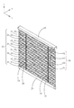
- FIG. 1 is a perspective view showing the blind according to the present invention, and is a view showing a state in which the blind slats 30 are erected.
- FIG. 2 is an enlarged cross-sectional view showing the blind slat 30 (the slat 30 for the blind in an upright position) in the blind shown in FIG. 1 cut by a plane perpendicular to the longitudinal direction of the slat 30 for the blind. ..
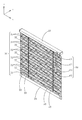
- FIG. 3 is a perspective view showing the blind according to the present invention, and is a view showing a state in which the blind slat 30 is tilted.
- FIG. 1 is a perspective view showing the blind according to the present invention, and is a view showing a state in which the blind slat 30 is tilted.
- FIG. 4 is an enlarged cross-sectional view showing the blind slat 30 (the slat 30 for the blind in an upright position) in the blind shown in FIG. 3 cut in a plane perpendicular to the longitudinal direction of the slat 30 for the blind. ..
- FIGS. 7 to 14 the x-axis, y-axis and z-axis are shown.
- the orientations of the x-axis, y-axis, and z-axis coincide with each other even in different figures.
- the positive side in the x-axis direction is the "right” side
- the negative side in the x-axis direction is the "left" side
- the positive side in the y-axis direction is the "outdoor” side or "rear” side
- the negative side in the y-axis direction is the "indoor" side.
- the "" side or "front” side, the positive side in the z-axis direction is sometimes called the "upper” side, and the negative side in the z-axis direction is sometimes called the “lower” side, but this is to express the relative positional relationship of each part. It is nothing more than a thing, and does not limit the absolute positional relationship of each part.
- the blind of the present invention is installed in an opening (window, etc.) for daylighting in a building or the like.
- This type of blind is usually arranged on the indoor side of a window or the like so as to cover substantially the entire opening of the window or the like.
- the blind shown in FIG. 1 is substantially parallel to the region between the head box 10 forming the upper portion of the blind, the bottom rail 20 forming the lower portion of the blind, and the head box 10 and the bottom rail 20.
- a plurality of arranged blind slats 30 hereinafter, abbreviated as "slats 30"
- an elevating cord 40 and a rudder cord 50 connecting the head box 10 and the bottom rail 20, and a head. It is provided with an operating means 60 provided on the indoor side from the box 10.
- the headbox 10 is fixed to the upper part of the opening to which the blind is attached (usually the upper rail of the window) to support the other part of the blind in a hanging state on the indoor side of the opening and to operate the brand. It is a part for accommodating various mechanical mechanisms (not shown).
- the bottom rail 20 is a portion that protects the lower portion of the blind and also functions as a weight of the blind.
- the slats 30 are in a state where the inclination can be changed, and are a portion having a function of adjusting the light entering the room from the outside.
- the number of slats 30 provided for one blind varies depending on the size of the blinds, the vertical width of each slats 30, and the like, and is not particularly limited.
- the number of slats 30 is usually about 30 to 80, and in the case of a blind installed in a sweep window, it is usually about 50 to 150. ..
- the blind shown in FIG. 1 is simplified and drawn with 16 slats 30.
- the elevating cord 40 is a part having a function of elevating and lowering the bottom rail 20 with respect to the head box 10.
- the elevating cord 40 is hung on a pulley (pulley for supporting the elevating cord) (not shown) housed in the head box 10 on the upper end side thereof, and is inserted through the inside of the tilt pole 62 in the operating means 60 to form an equalizer 64. It is fixed to.
- the lower end of the elevating cord 40 is fixed to the bottom rail 20.
- the portion of the elevating cord 40 located between the head box 10 and the bottom rail 20 is in a state of being inserted into a through hole provided in each slat 30.
- the bottom rail 20 is raised while the slats 30 are vertically overlapped, and the blind is pulled upward.
- the blind raised upward is designed to be lowered when the equalizer 64 is slightly pulled down and the hand is released.
- the ladder cord 50 forms a ladder shape composed of a pair of front and rear vertical strings (strings extending in the vertical direction) and a plurality of horizontal strings arranged in the front-rear direction while connecting the pair of front and rear vertical strings. ing.
- the slat 30 is arranged between a pair of front and rear vertical cords in the ladder cord 50, and the lower surface of each slat 30 is supported by each horizontal cord in the ladder cord 50.
- the upper end side of the pair of front and rear vertical cords in the rudder cord 50 is attached to a gear (a gear for supporting the rudder cord) (not shown) housed in the head box 10, and the gear for supporting the rudder cord rotates in one direction.
- the slat 30 is raised from the closed state (the gap between the slat 30 becomes invisible or the gap is narrowed).
- FIGS. 3 and 4 when the slat 30 is in an inclined open state (a state in which the gap between the slat 30 is wider than in the closed state), when the grip 63 is rotated to the other side, FIGS. 3 and 4 As shown in FIG. 1, the slats 30 are changed from the tilted open state to the upright closed state as shown in FIGS. 1 and 2.
- the slat 30 rotates in an inverted position or in an upright position, so that the gap between the slat 30 changes, and the amount of light entering from the outdoor side to the indoor side through the gap can be adjusted. It has become. Further, when the grip 63 is rotated, the lodging angle of the slat 30 changes, and the degree of reflection of the light hitting the slat 30 can be adjusted.
- the operating means 60 operates the elevating cord 40 and the ladder cord 50.
- the operating means 60 includes a tilter 61, a tilt pole 62, a grip 63, and an equalizer 64.
- the equalizer 64 when the equalizer 64 is operated, the blind is raised and lowered, and when the grip 63 is operated, the slats 30 are opened and closed (the operation of switching between the open state and the closed state). ..
- the operating means 60 is a so-called one-pole type that can both raise and lower the blind and open and close the slat 30.
- the operating means 60 is not limited to the one-pole type, and other mechanisms may be adopted.
- the elevating operation of the blind is performed by the elevating operation string (not shown) hanging from the head box 10, and the opening / closing operation of the slats 30 is performed by the rotation operation of the grip 63 (in the case of the structure, the equalizer 64 is unnecessary). It is also possible.
- the slats 30 change the lighting state of the blinds by standing or tilting.
- the slats 30 are formed of a film (resin film) made of a resin having excellent impact resistance, heat resistance and flame retardancy.
- a processed strip-shaped base material using polycarbonate as a main raw material is used as the slats 30. Therefore, heat is less likely to be accumulated in the slat 30, the slat 30 is prevented from becoming hot, and the cooling efficiency can be improved when the outdoors such as summer are hot.
- the slats 30 are made lightweight and flexible so that the blinds are less likely to break down and even if a person touches the slats 30, they are less likely to be injured.
- the slats 30 have a V-shaped cross section as shown in FIGS. 2 and 4. That is, the slats 30 are composed of a flat plate-shaped first portion 30a and a flat plate-shaped second portion 30b provided so as to be inclined with respect to the first portion 30a, and are perpendicular to the longitudinal direction (x-axis direction) thereof.
- the cross-sectional shape is V-shaped.
- the opening angle ⁇ of the slat 30 is not particularly limited as long as it is smaller than 180 °, preferably 100 to 175 °, and more preferably 130 to 170 °. It is more preferably 150 to 165 °. In the examples shown in FIGS. 2 and 4, the opening angle ⁇ of the slat 30 is 160 °.
- Width W a of the first portion 30a of the slat 30 (FIG. 4) and a width W b (FIG. 4) of the second portion 30b is not particularly limited, and may be different values. However, if the width W a and the width W b are set to different values, the portion where multiple diffuse reflections as shown in FIG. 4 occur is reduced. Therefore, the ratio W b / W a width W b of the width W a, preferably in the range of 0.25-4, more preferably in the range of 0.5 to 2, 0.67 to It is more preferably in the range of 1.5. In the example shown in FIGS.
- the width W a and the width W b is set substantially equal, the ratio W b / W a is set to be approximately 1.
- the width W a and the width W b are usually 5 to 30 mm, preferably 10 to 20 mm, respectively.
- the thickness (plate thickness) of the slat 30 is also not particularly limited, but if it is made too thin, it may be difficult to maintain the strength of the slat 30. Therefore, the thickness of the slats 30 is usually 100 ⁇ m or more.
- the thickness of the slats 30 is preferably 150 ⁇ m or more, more preferably 200 ⁇ m or more, and even more preferably 250 ⁇ m or more.
- the slat 30 is made too thick, not only the weight of the slat 30 becomes large, but also it becomes difficult to wind the strip-shaped base material (resin film) forming the slat 30 in a roll shape, and the yield decreases.
- the thickness of the slats 30 is usually set to 500 ⁇ m or less.
- the thickness of the slats 30 is preferably 400 ⁇ m or less, more preferably 350 ⁇ m or less, and even more preferably 300 ⁇ m or less.
- the band-shaped base material forming the slats 30 is a resin film cut into a band shape, and even if the band-shaped base material (resin film) is bent into a V-shaped cross section, the strip-shaped base material is used.
- the strip-shaped base material tends to return to the side where the V-shaped opening (the above-mentioned opening angle ⁇ ) becomes large (springback occurs).
- the above-mentioned springback is made by using a resin mainly made of polycarbonate which is easily creases and is less likely to cause springback.
- the bending method is also devised.
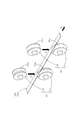
- FIG. 5 and 6 are perspective views showing a state in which the strip-shaped base material 30c is bent to form a slats 30.
- FIG. 5 shows a state in which the strip-shaped base material 30c is arranged between the bending rollers 70 (between the bending push roller 71 and the bending receiving roller 72), and
- FIG. 6 shows the strip-shaped base material 30c.
- the state of being bent by being sandwiched between the bending rollers 70 is shown.
- the folding roller 70 in FIGS. 5 and 6 is for bending the strip-shaped base material 30c.
- the bending roller 70 is composed of a bending push roller 71 and a bending receiving roller 72.
- the bending push roller 71 is provided with an annular protrusion 71a having a V-shaped cross section on the outer peripheral portion
- the bending receiving roller 72 is provided with an annular groove 72a having a V-shaped cross section on the outer peripheral portion. ..
- the V-shaped opening angle in the cross section of the annular protrusion 71a and the V-shaped opening angle in the cross section of the annular groove 72a are both set to be substantially the same as the opening angle ⁇ (FIG. 4) of the slat 30.
- a strip-shaped base material 30c (flat strip-shaped base material 30c) before bending is arranged between the bending push roller 71 and the bending receiving roller 72 constituting the bending roller 70.
- strip-like base material between the roller 72 receives a bending and pressing for bending roller 71
- 30c is sandwiched. In this state, when pulling the strip-like base material 30c in the direction of arrow A 2, as shown in FIG.
- FIGS. 5 and 6 also show a transfer roller 80.
- Carrying roller 80 has a one for conveying the strip-like base material 30c in the direction of arrow A 2.
- the transport roller 80 is composed of a transport push roller 81 and a transport receiving roller 82.
- the transport pushing roller 81 is provided with an annular protrusion 81a having an arcuate cross section on the outer peripheral portion
- the transport receiving roller 82 is provided with an annular groove 82a having an arcuate cross section on the outer peripheral portion.
- the transport push roller 81 has an arrow A 3 in a state where the strip-shaped base material 30c is sandwiched between the annular protrusion 81a of the transport push roller 81 and the annular groove portion 82a of the transport receiving roller 82.
- a rotary drive means such as a motor (not shown) is connected to the transport push roller 81.
- pressed conveyance roller 81 is rotated in the direction of arrow A 3, by frictional force, also rotates in the direction of arrow A 4 receives conveyance roller 82.
- the roller 72 receives a folding roller 71 press for folding, rotating in the arrow A 5 direction of the arrow A 6, respectively.
- the transport roller 80 is provided at a position different from that of the bending roller 70.
- the bending push roller 71 is connected to the rotation driving means.
- the bending roller 70 can also function as the transport roller 80.
- the transport roller 80 is provided at a position downstream of the bending roller 70 and at a certain distance from the bending roller 70.
- the strip-shaped base material 30c bent by the bending roller 70 is passed between the transport rollers 80 (between the transport push roller 81 and the transport receiving roller 82), the desired opening is achieved by the bending roller 70.
- the form of the strip-shaped base material 30c bent at an angle ⁇ may be changed by the transport roller 80.
- the transport roller 80 has the same shape as the bending roller 70 (a band-shaped base material 30c is sandwiched between an annular protrusion having a V-shaped cross section and an annular groove), the above problem can be solved. be able to.
- the position of the strip-shaped base material 30c is slightly displaced, there is a possibility that double creases are formed on the strip-shaped base material 30c.
- the opening angle ⁇ of the slat 30 is changed by setup change or the like, it is necessary to replace not only the bending roller 70 but also the transport roller 80, which is troublesome.
- the annular protrusion 81a of the transfer push roller 81 and the annular groove 82a of the transfer receiving roller 82 are formed in an arcuate cross section to form a strip from the transfer roller 80. While the conveying force is applied to the base material 30c, the band-shaped base material 30c is prevented from having an extra habit such as a new crease. That is, since the strip-shaped base material 30c passing between the transport pushing roller 81 and the transport receiving roller 82 is only gently and smoothly curved by the annular protrusion 81a and the annular groove 82a, the transport roller 80 After being fed out from, it returns to the state of V-shaped cross section.
- the strip-shaped base material 30c forming the slats 30 is made of polycarbonate as a main raw material.
- Polycarbonate is usually colorless and transparent.
- pigments can also be blended in the strip-shaped base material 30c.
- titanium oxide (TiO 2 ) can be preferably used as the pigment. Titanium oxide not only has high light-shielding properties, has low activity as a catalyst, and has excellent thermal stability, but also has a white color by itself, so that it is not necessary to use other pigments or the like. , The slats 30 can be colored in a clean white color.
- a light diffusing material can be blended in the strip-shaped base material 30c.
- the light diffusing material light diffusing beads can be preferably used.
- the slats 30 can be made excellent in light diffusing property.
- the light diffusivity of the slats 30 is enhanced not only by the method of blending the light diffusing material in the band-shaped base material 30c, but also by the unevenness for light diffusion (many fine unevenness formed by embossing or the like) on the surface of the band-shaped base material. be able to.
- the characteristics of the slats 30 can be changed by blending the pigment or the light diffusing material with the strip-shaped base material 30c. For example, if the amount of the pigment compounded is small, the light transmittance of the slat 30 is increased, and the slat 30 is diffused while transmitting the light incident on the slat 30, and if the amount of the pigment compounded is large, the slat 30 is diffused. The light transmittance can be kept low, and the slats 30 can be diffused while reflecting the light incident on the slats 30.
- the slats 30 having a high light transmittance of 20 to 90% are referred to as “transmission diffusion type slats”, and the slats 30 having a low light transmittance of 15% or less are referred to as “reflection diffusion type slats”.
- transmission diffusion type slats the slats 30 having a high light transmittance of 20 to 90%
- reflection diffusion type slats the slats 30 having a low light transmittance of 15% or less.
- a plurality of slats 30 are provided, and these plurality of slats 30 may be composed of only one of the above-mentioned transmission diffusion type and reflection diffusion type. If the blind is composed of only the transmission / diffusion type slats 30, the room can be brightened even when the slats 30 are closed, and if the blind is composed of only the reflection / diffusion type slats 30, the slats 30 can be formed. It is possible to suppress the amount of light that is introduced into the room when it is closed. However, if the blind is formed by combining the reflection / diffusion type slat 30 and the transmission / diffusion type slat 30, it is possible to perform appropriate daylighting according to the installation location of the blind.
- the reflection diffusion type slat 30 and the transmission diffusion type slat 30 are combined.
- the blinds from the first embodiment to the eighth embodiment will be described as an example.
- the description of the configuration common to the above-mentioned blinds (blinds described with reference to FIGS. 1 to 4) will be omitted.
- the same configuration as the blind described above can be adopted for the configuration not particularly mentioned.
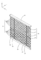
- FIG. 7 is a perspective view showing the blind of the first embodiment in a state where the slats 30 are upright.
- the reflection diffusion type slat 30 (slat 31) is shown by finely meshed hatching for convenience of explanation, and the transmission diffusion type slat 30 (slat 32) is shown. Is shown by shaded hatching with large eyes.
- the reflection diffusion type slat 31 is arranged in the lower half area of the blind, and the transmission diffusion type slat 32 is arranged in the upper half area of the blind. Is arranged.
- the reflection / diffusion type slat 31 reflects the light incident on it while diffusing it, and the transmission / diffusion type slat 32 transmits the light incident on the slat 32 while diffusing it. It has become. Therefore, the light transmittance of the reflection / diffusion type slat 31 is suppressed to 15% or less, while the light transmittance of the transmission / diffusion type slat 32 is 20 to 90%, which is higher than that of the reflection / diffusion type slat 31. It has become.
- the transmission diffusion type slats 32 are arranged in the upper region of the blind, the upper space (usually near the ceiling) in the room is illuminated by the diffused light, and the room is illuminated by the joint light. It is possible to create a good atmosphere as if it were illuminated.
- the reflection-diffuse type slat 31 reflects most of the light (sunlight, etc.) from the outside to the outside in the upright state (closed state), and hardly leads to the inside of the room. It has become.
- the reflection-diffuse type slat 31 reflects light, in addition to transmitting light to some extent with a light transmittance of 15% or less, the reflection-diffuse type slat 31 can be seen through the gap between adjacent reflection-diffuse slat 31s. , The light diffusely reflected by the reflection diffusion type slat 31 will leak out.
- the indoor surface of the reflection diffusion type slat 31 is in a state where a wide range thereof is dimly and brightly illuminated.
- the light reflected or transmitted by the reflection-diffuse type slats 31 is diffused light, and the amount of light is considerably weakened, so that the light is not so dazzling or heat-sensitive.
- the reflection / diffusion type slats 31 are arranged in the lower region of the blind, the reflection on the screen of a personal computer installed on the desk near the window can be suppressed.
- the blind of the first embodiment is not too dazzling while blocking the direct oblique light into the room, and is reflected on the screen of the personal computer or the like. It is possible to illuminate the interior of the room brightly in a comfortable state that does not cause any problems.
- the width of the gap between the adjacent slat 30, that is, the amount of light introduced into the room through the gap between the slat 30, can be adjusted by changing the inclination angle ⁇ (see FIG. 4) of the slat 30.
- the light transmittance of the reflection-diffuse type slat 31 is not particularly limited as long as it is 15% or less (85% or more in terms of light reflectance).
- the light transmittance of the reflection / diffusion type slats 31 Is preferably 10% or less (90% or more in terms of light reflectance).
- the light transmittance of the reflection / diffusion type slats 31 is more preferably 9% or less (91% or more in terms of light reflectance), and 8% or less (92% or more in terms of light reflectance). Is even more preferable.
- the light transmittance of the transmission / diffusion type slats 32 is not particularly limited as long as it is 20 to 90% as described above. However, in order to secure the brightness of the region where the transmission / diffusion type slat 32 is arranged, the light transmittance of the transmission / diffusion type slat 32 is preferably 30% or more. The light transmittance of the transmission / diffusion type slats 32 is more preferably 40% or more, further preferably 50% or more, and particularly preferably 60% or more. On the other hand, if the light transmittance of the transmission / diffusion type slat 32 is made too high, the region where the transmission / diffusion type slat 32 is arranged may become too dazzling.
- the light transmittance of the transmission / diffusion type slats 32 is preferably 85% or less.
- the light transmittance of the transmission / diffusion type slats 32 is more preferably 80% or less.
- the light transmittance of the transmission / diffusion type slats 32 is 70%.
- the blind of the first embodiment described above creates an atmosphere in the room by introducing natural and soft light into the room not only in the open state where the slat 30 is tilted but also in the closed state where the slat 30 is erected. It is something that can be kept bright. In addition, it is possible to make it difficult for a person in the room to feel glare or heat, and to make it difficult for reflection to occur on the screen of a personal computer or the like in the room.
- the transmission diffusion type slat 32 is arranged in the upper half region thereof, and the reflection diffusion type slat 31 is arranged in the lower half region thereof.
- the arrangement of the transmission diffusion type slat 31 and the reflection diffusion type slat 32 is not limited to this.
- the arrangement of the transmission diffusion type slat 31 and the reflection diffusion type slat 32 can be appropriately changed depending on the installation location of the blinds and the like. This point will be described below.
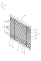
- FIG. 8 is a perspective view showing the blind of the second embodiment in a state where the slats 30 are upright.
- the reflection diffusion type slat 31 is arranged in the upper half region thereof
- the transmission diffusion type slat 32 is arranged in the lower half region thereof. are doing. That is, in the blind of the second embodiment, the arrangement of the reflection diffusion type slat 31 and the transmission diffusion type slat 32 is opposite to that of the blind of the first embodiment. This makes it possible to provide bright blinds in the lower region even when the slats 30 are upright and closed.
- FIG. 9 is a perspective view showing the blind of the third embodiment in a state where the slats 30 are upright.
- FIG. 10 is a perspective view showing the blind of the fourth embodiment in a state where the slats 30 are upright.
- the blinds of the first embodiment and the second embodiment described above the blinds are divided into two regions by the reflection diffusion type slats 31 and the transmission diffusion type slats 32, but the third embodiment and the fourth embodiment have been divided into two regions.
- the blind of the embodiment as shown in FIGS. 9 and 10 the blind is divided into three regions by the reflection diffusion type slat 31 and the transmission diffusion type slat 32.
- the transmission / diffusion type slats 32 are arranged in the upper approximately one-quarter region and the lower approximately one-quarter region, and the central part. Reflective diffusion type slats 31 are arranged in approximately half of the area.
- reflection diffusion type slats 31 are arranged in a substantially quarter area on the upper side and a substantially quarter area on the lower side, and the center The transmission / diffusion type slats 32 are arranged in approximately half of the area.
- the blind can be divided into three or more regions by the reflection diffusion type slat 31 and the transmission diffusion type slat 32.
- FIG. 11 is a perspective view showing the blind of the fifth embodiment in a state where the slats 30 are upright.
- one reflection / diffusion region is composed of a plurality of reflection / diffusion type slats 31, and one transmission / diffusion region is composed of a plurality of transmission / diffusion.
- one reflection diffusion region is composed of one reflection diffusion type slat 31 and one transmission diffusion.
- the region is composed of one transmission / diffusion type slats 32.
- the reflection diffusion type slat 31 and the transmission diffusion type slat 32 are alternately arranged one by one. Such an arrangement is also possible.
- FIG. 12 is a perspective view showing the blind of the sixth embodiment in a state where the slats 30 are upright. In the blind of the sixth embodiment, as shown in FIG.
- one reflection / diffusion region is composed of two reflection / diffusion type slats 31, and one transmission / diffusion region is two transmission / diffusion type slats. It is composed of 32.
- two reflection-diffuse slat 31s and two transmission-diffuse slat 32 are alternately arranged.
- FIG. 13 is a perspective view showing the blind of the seventh embodiment in a state where the slats 30 are upright.
- the number of the reflection diffusion type slat 31 and the number of the transmission diffusion type slat 32 were the same, but the seventh embodiment.
- a set consisting of two reflection-diffuse type slat 31 and one transmission-diffuse type slat 32 is repeatedly arranged, and the number of reflection-diffuse type slat 31 is increased.
- the number of transmission / diffusion type slats 32 is different. In this way, it is possible to make the number of the reflection-diffuse type slat 31 different from the number of the transmission-diffuse type slat 32.
- FIG. 14 is a perspective view showing the blind of the eighth embodiment in a state where the slats 30 are upright.
- the reflection-diffuse type slat 31 and the transmission-diffuse type slat 32 were periodically and regularly arranged, but the blind of the eighth embodiment.
- the number of slat 30s constituting each region gradually decreases from the upper side to the lower side of the blind, and the reflection diffusion type slat 31 and the transmission diffusion type slat 32 Are not arranged periodically.
- the reflection diffusion type slat 31 and the transmission diffusion type slat 32 can be arranged aperiodically.
- the reflection diffusion type slat 31 and the transmission diffusion type slat 32 should be arranged completely irregularly. Therefore, even when the reflection / diffusion type slat 31 and the transmission / diffusion type slat 32 are arranged aperiodically, the number of slat 30 constituting each region gradually decreases from the upper side to the lower side of the blind. On the contrary, it is preferable to arrange the gradation in such a manner that the number gradually increases from the upper side to the lower side of the blind.
Landscapes
- Engineering & Computer Science (AREA)
- Structural Engineering (AREA)
- Architecture (AREA)
- Civil Engineering (AREA)
- Mechanical Engineering (AREA)
- Blinds (AREA)
Priority Applications (3)
| Application Number | Priority Date | Filing Date | Title |
|---|---|---|---|
| JP2019536238A JP7344554B2 (ja) | 2019-03-25 | 2019-03-25 | ブラインド用スラットの製造方法及びブラインドの製造方法 |
| KR1020197019459A KR102753875B1 (ko) | 2019-03-25 | 2019-03-25 | 블라인드용 슬랫 및 그 제조 방법과 블라인드 |
| PCT/JP2019/012451 WO2020194437A1 (ja) | 2019-03-25 | 2019-03-25 | ブラインド用スラット及びその製造方法並びにブラインド |
Applications Claiming Priority (1)
| Application Number | Priority Date | Filing Date | Title |
|---|---|---|---|
| PCT/JP2019/012451 WO2020194437A1 (ja) | 2019-03-25 | 2019-03-25 | ブラインド用スラット及びその製造方法並びにブラインド |
Publications (1)
| Publication Number | Publication Date |
|---|---|
| WO2020194437A1 true WO2020194437A1 (ja) | 2020-10-01 |
Family
ID=72609214
Family Applications (1)
| Application Number | Title | Priority Date | Filing Date |
|---|---|---|---|
| PCT/JP2019/012451 Ceased WO2020194437A1 (ja) | 2019-03-25 | 2019-03-25 | ブラインド用スラット及びその製造方法並びにブラインド |
Country Status (3)
| Country | Link |
|---|---|
| JP (1) | JP7344554B2 (https=) |
| KR (1) | KR102753875B1 (https=) |
| WO (1) | WO2020194437A1 (https=) |
Citations (6)
| Publication number | Priority date | Publication date | Assignee | Title |
|---|---|---|---|---|
| JPS55153623A (en) * | 1979-05-18 | 1980-11-29 | Toosoo Kk | Method and apparatus for working slat |
| US4792427A (en) * | 1983-05-13 | 1988-12-20 | Nanik Division Wausau Metals Corporation | Method for making light-transmitting slats for blind |
| JPH0450794Y2 (https=) * | 1986-04-17 | 1992-11-30 | ||
| JP2006291520A (ja) * | 2005-04-08 | 2006-10-26 | Toppan Printing Co Ltd | 光拡散ブラインド |
| WO2016175207A1 (ja) * | 2015-04-30 | 2016-11-03 | シャープ株式会社 | 採光システム |
| JP2019082053A (ja) * | 2017-10-31 | 2019-05-30 | 株式会社あかりカンパニー | ブラインド |
Family Cites Families (6)
| Publication number | Priority date | Publication date | Assignee | Title |
|---|---|---|---|---|
| JPS60118295U (ja) * | 1984-01-19 | 1985-08-09 | 大日本印刷株式会社 | 電磁波シ−ルド用複合シ−ト |
| JPH0617991Y2 (ja) * | 1986-07-01 | 1994-05-11 | 鹿島建設株式会社 | 横型ブラインド |
| JP3727252B2 (ja) | 2001-05-29 | 2005-12-14 | Tdk株式会社 | 蛍光x線分析用試料、及び蛍光x線分析方法 |
| JP2004263032A (ja) | 2003-02-28 | 2004-09-24 | Tsutsunaka Plast Ind Co Ltd | 絶縁材料用樹脂フィルム |
| KR101239473B1 (ko) | 2011-08-01 | 2013-03-06 | 주식회사 포스코 | 산세액 및 스테인리스강의 산세방법 |
| JP6245500B2 (ja) * | 2013-06-19 | 2017-12-13 | 大日本印刷株式会社 | ブラインドおよび照明装置 |
-
2019
- 2019-03-25 WO PCT/JP2019/012451 patent/WO2020194437A1/ja not_active Ceased
- 2019-03-25 JP JP2019536238A patent/JP7344554B2/ja active Active
- 2019-03-25 KR KR1020197019459A patent/KR102753875B1/ko active Active
Patent Citations (6)
| Publication number | Priority date | Publication date | Assignee | Title |
|---|---|---|---|---|
| JPS55153623A (en) * | 1979-05-18 | 1980-11-29 | Toosoo Kk | Method and apparatus for working slat |
| US4792427A (en) * | 1983-05-13 | 1988-12-20 | Nanik Division Wausau Metals Corporation | Method for making light-transmitting slats for blind |
| JPH0450794Y2 (https=) * | 1986-04-17 | 1992-11-30 | ||
| JP2006291520A (ja) * | 2005-04-08 | 2006-10-26 | Toppan Printing Co Ltd | 光拡散ブラインド |
| WO2016175207A1 (ja) * | 2015-04-30 | 2016-11-03 | シャープ株式会社 | 採光システム |
| JP2019082053A (ja) * | 2017-10-31 | 2019-05-30 | 株式会社あかりカンパニー | ブラインド |
Also Published As
| Publication number | Publication date |
|---|---|
| KR20210140832A (ko) | 2021-11-23 |
| JPWO2020194437A1 (https=) | 2020-10-01 |
| JP7344554B2 (ja) | 2023-09-14 |
| KR102753875B1 (ko) | 2025-01-14 |
Similar Documents
| Publication | Publication Date | Title |
|---|---|---|
| EP2565358B1 (en) | Multi-piece combined lifting louver blade | |
| AU2008200367B2 (en) | Daylighting system comprising light redirection elements in a venetian blind | |
| US20120011782A1 (en) | Fenestration system with solar cells | |
| US10480736B2 (en) | Daylighting system | |
| EP2557263B1 (en) | Multi-piece combined turnover louver blade | |
| US10344531B2 (en) | Daylighting slat and daylighting device | |
| WO2016002869A1 (ja) | 採光スラット及び採光装置 | |
| US20150184457A1 (en) | Louver Roller System with Cam Pin Turning Mechanism | |
| KR102362780B1 (ko) | 높은 반사율을 가지는 슬랫, 이의 제조방법 및 이를 구비하는 블라인드 장치 | |
| JP5991455B2 (ja) | 採光ブラインド | |
| WO2020194437A1 (ja) | ブラインド用スラット及びその製造方法並びにブラインド | |
| EP3411555B1 (en) | A blind with light guiding louvers | |
| JP7006919B2 (ja) | ブラインド | |
| JP2013002224A (ja) | 熱線遮蔽機能付き採光ブラインド及び熱線遮蔽機能付き遮光・採光両用ブラインド及び照明システム | |
| JP6757467B2 (ja) | 採光装置 | |
| WO2012009956A1 (zh) | 双功能百叶片 | |
| JP3138621U (ja) | 入射光を反射収集及び調光するシェード | |
| JP2019008956A (ja) | 採光装置 | |
| WO2018079709A1 (ja) | 調光ブラインド、採光装置および照明システム | |
| JP2020153143A (ja) | ロールスクリーン | |
| WO2018186435A1 (ja) | 採光装置 | |
| JP2018127788A (ja) | ルーバー | |
| JPWO2018066264A1 (ja) | 採光スラット及び採光装置 |
Legal Events
| Date | Code | Title | Description |
|---|---|---|---|
| ENP | Entry into the national phase |
Ref document number: 2019536238 Country of ref document: JP Kind code of ref document: A |
|
| ENP | Entry into the national phase |
Ref document number: 20197019459 Country of ref document: KR Kind code of ref document: A |
|
| 121 | Ep: the epo has been informed by wipo that ep was designated in this application |
Ref document number: 19922059 Country of ref document: EP Kind code of ref document: A1 |
|
| NENP | Non-entry into the national phase |
Ref country code: DE |
|
| 122 | Ep: pct application non-entry in european phase |
Ref document number: 19922059 Country of ref document: EP Kind code of ref document: A1 |