WO2020189689A1 - アルミニウム基線材 - Google Patents
アルミニウム基線材 Download PDFInfo
- Publication number
- WO2020189689A1 WO2020189689A1 PCT/JP2020/011822 JP2020011822W WO2020189689A1 WO 2020189689 A1 WO2020189689 A1 WO 2020189689A1 JP 2020011822 W JP2020011822 W JP 2020011822W WO 2020189689 A1 WO2020189689 A1 WO 2020189689A1
- Authority
- WO
- WIPO (PCT)
- Prior art keywords
- layer
- wire
- core wire
- thickness
- base
- Prior art date
- Legal status (The legal status is an assumption and is not a legal conclusion. Google has not performed a legal analysis and makes no representation as to the accuracy of the status listed.)
- Ceased
Links
Images


Classifications
-
- C—CHEMISTRY; METALLURGY
- C22—METALLURGY; FERROUS OR NON-FERROUS ALLOYS; TREATMENT OF ALLOYS OR NON-FERROUS METALS
- C22C—ALLOYS
- C22C13/00—Alloys based on tin
-
- C—CHEMISTRY; METALLURGY
- C22—METALLURGY; FERROUS OR NON-FERROUS ALLOYS; TREATMENT OF ALLOYS OR NON-FERROUS METALS
- C22C—ALLOYS
- C22C18/00—Alloys based on zinc
-
- C—CHEMISTRY; METALLURGY
- C22—METALLURGY; FERROUS OR NON-FERROUS ALLOYS; TREATMENT OF ALLOYS OR NON-FERROUS METALS
- C22C—ALLOYS
- C22C21/00—Alloys based on aluminium
-
- C—CHEMISTRY; METALLURGY
- C25—ELECTROLYTIC OR ELECTROPHORETIC PROCESSES; APPARATUS THEREFOR
- C25D—PROCESSES FOR THE ELECTROLYTIC OR ELECTROPHORETIC PRODUCTION OF COATINGS; ELECTROFORMING; APPARATUS THEREFOR
- C25D5/00—Electroplating characterised by the process; Pretreatment or after-treatment of workpieces
- C25D5/10—Electroplating with more than one layer of the same or of different metals
- C25D5/12—Electroplating with more than one layer of the same or of different metals at least one layer being of nickel or chromium
-
- C—CHEMISTRY; METALLURGY
- C25—ELECTROLYTIC OR ELECTROPHORETIC PROCESSES; APPARATUS THEREFOR
- C25D—PROCESSES FOR THE ELECTROLYTIC OR ELECTROPHORETIC PRODUCTION OF COATINGS; ELECTROFORMING; APPARATUS THEREFOR
- C25D7/00—Electroplating characterised by the article coated
- C25D7/06—Wires; Strips; Foils
-
- H—ELECTRICITY
- H01—ELECTRIC ELEMENTS
- H01B—CABLES; CONDUCTORS; INSULATORS; SELECTION OF MATERIALS FOR THEIR CONDUCTIVE, INSULATING OR DIELECTRIC PROPERTIES
- H01B5/00—Non-insulated conductors or conductive bodies characterised by their form
- H01B5/02—Single bars, rods, wires, or strips
Definitions
- the present disclosure relates to an aluminum base wire.
- This application claims the priority based on Japanese Patent Application No. 2019-053850 of the Japanese application dated March 20, 2019, and incorporates all the contents described in the Japanese application.
- the aluminum alloy wire of Patent Document 1 includes a coating layer that covers the outer periphery of the alloy wire.
- the coating layer has an intermediate layer formed on the alloy wire side and an outermost layer formed on the outermost side.
- the intermediate layer has a one-layer structure or a two-layer structure.
- Each layer is composed of nickel or copper.
- the outermost layer is made of tin or a tin alloy.
- the alloy wire is referred to as a core wire.
- the aluminum baseline material according to the present disclosure is with a core wire made of pure aluminum or aluminum alloy, A coating layer provided on the outer periphery of the core wire is provided.
- the coating layer is The first layer provided on the outer circumference of the core wire and The second layer provided on the outer circumference of the first layer and It has a third layer provided on the outer periphery of the second layer, and has a third layer.
- the first layer is composed of at least one metal selected from the group consisting of nickel, iron, cobalt, chromium, copper, silver, and alloys of these elements.
- the second layer is composed of a metal containing zinc and tin.
- the third layer is composed of at least one metal selected from the group consisting of tin and a substantially zinc-free tin alloy.
- the zinc content in the second layer is 15 atomic% or more and 60 atomic% or less.
- FIG. 1 is a cross-sectional view showing an outline of the aluminum base wire according to the first embodiment.
- FIG. 2 is an enlarged view showing an enlarged region of the aluminum base wire shown in FIG. 1 surrounded by a broken line rectangular frame.
- FIG. 3 is an enlarged view showing a part of a cross section of the aluminum base wire according to the second embodiment in an enlarged manner.
- FIG. 4 shows the sample No. 6 is a photomicrograph showing a cross section of a second layer provided in the aluminum base wire of No. 6.
- FIG. 5 shows the sample No. 6 is a photomicrograph showing the outer peripheral surface of the end portion of the aluminum base wire of No. 6.
- FIG. 6 shows the sample No. It is a micrograph which shows the end face of the aluminum base wire of 6.
- FIG. 1 is a cross-sectional view showing an outline of the aluminum base wire according to the first embodiment.
- FIG. 2 is an enlarged view showing an enlarged region of the aluminum base wire shown in FIG. 1 surrounded by a broken line
- FIG. 7 shows the sample No. 6 is a photomicrograph showing the outer peripheral surface of the aluminum base wire of No. 6 during bending.
- FIG. 8 shows the sample No. 19 is a photomicrograph showing the outer peripheral surface of the end portion of the aluminum base wire.
- FIG. 9 shows the sample No. 19 is a photomicrograph showing the end faces of the aluminum baselines.
- the core wire, the intermediate layer, and the outermost layer are made of different metals from each other.
- the intermediate layer is composed of nickel or copper
- the potential difference between the core wire and the intermediate layer becomes larger than the potential difference between the intermediate layer and the outermost layer. Therefore, if moisture adheres to the contact portion of the dissimilar metal through a pinhole or the like that reaches the surface of the core wire from the surface of the coating layer, the peripheral surface of the core wire is corroded. This corrosion is called galvanic corrosion.
- one of the purposes of the present disclosure is to provide an aluminum base wire having both corrosion resistance and workability of the core wire.
- Another object of the present disclosure is to provide an aluminum base wire having excellent corrosion resistance at the end face of the core wire.
- the aluminum base wire material according to the present disclosure is excellent in corrosion resistance and workability of the core wire.
- the aluminum base wire according to one aspect of the present disclosure is with a core wire made of pure aluminum or aluminum alloy, A coating layer provided on the outer periphery of the core wire is provided.
- the coating layer is The first layer provided on the outer circumference of the core wire and The second layer provided on the outer circumference of the first layer and It has a third layer provided on the outer periphery of the second layer, and has a third layer.
- the first layer is composed of at least one metal selected from the group consisting of nickel, iron, cobalt, chromium, copper, silver, and alloys of these elements.
- the second layer is composed of a metal containing zinc and tin.
- the third layer is composed of at least one metal selected from the group consisting of tin and a substantially zinc-free tin alloy.
- the zinc content in the second layer is 15 atomic% or more and 60 atomic% or less.
- the above configuration is excellent in corrosion resistance and workability of the core wire.
- the above configuration is particularly excellent in bending workability.
- the reason why the core wire is excellent in corrosion resistance is that the corrosion of the core wire can be suppressed by allowing the second layer to function as a sacrificial layer that is preferentially corroded over the core wire.
- the zinc content in the second layer is 15 atomic% or more, the zinc content in the second layer is high. Therefore, the potential difference between the first layer and the second layer is larger than the potential difference between the core wire and the first layer.
- the aluminum base wire may be referred to as an Al base wire.
- the above configuration is excellent in adhesion between the core wire and the coating layer. This is because the first layer has good compatibility with both the core wire and the second layer.
- the above configuration makes it easy to suppress contact resistance with the terminal member in applications where it is connected to the following terminal member.
- the terminal member include those made of copper or a copper alloy, and those having a main body made of copper or a copper alloy and a Sn layer formed on the surface of the main body.
- the Sn layer include a Sn plating layer.
- the reason why the contact resistance is easily suppressed is that the contact surface of the Al base wire with the terminal member is composed of a third layer made of a tin-based metal. If the amount of zinc present on the contact surface side of the Al base wire with the terminal member is too large, the contact resistance between the Al base wire and the terminal member increases. However, by having the third layer formed on the second layer containing a large amount of zinc, the coating layer can prevent the connection between the second layer and the terminal member.
- the structure of the second layer has a dispersed structure in which the second phase containing zinc as a main component is dispersed in the first phase containing tin as a main component.
- the size of the second phase is 0.01 ⁇ m or more and 1 ⁇ m or less.
- the Al base wire has excellent corrosion resistance of the core wire.
- the second layer has a sufficient size, so that the second layer easily functions as a sacrificial layer.
- the Al baseline is excellent in workability.
- the second layer has a sufficient size so that the second layer does not become too hard.
- the size of the second phase is 1 ⁇ m or less, the Al base wire has excellent corrosion resistance of the core wire. The reason is that the second phase is unlikely to be sparse.
- the ratio D2 / D1 of the thickness D1 of the first layer to the thickness D2 of the second layer is 5 or more.
- the above configuration makes it easy to suppress corrosion of the core wire.
- the reason is that the thickness D2 of the second layer is sufficiently thicker than the thickness D1 of the first layer, so that the second layer is more likely to be corroded preferentially than the core wire.
- the thickness D1 of the first layer is 0.05 ⁇ m or more and 1 ⁇ m or less.
- the Al baseline material having a thickness D1 of the first layer of 0.05 ⁇ m or more is excellent in corrosion resistance of the core wire because the thickness D1 of the first layer is sufficiently thick.
- the Al baseline material having a thickness D1 of the first layer of 1 ⁇ m or less is excellent in workability because the thickness D1 of the first layer is not excessively thick.
- the thickness D2 of the second layer may be 0.5 ⁇ m or more.
- the thickness D2 of the second layer is sufficiently thick, so that the core wire has excellent corrosion resistance.
- the thickness D3 of the third layer is 1.5 ⁇ m or more.
- the above configuration makes it easy to suppress an increase in contact resistance with the terminal member.
- the reason is that the thickness D3 of the third layer is sufficiently thick, so that zinc is difficult to diffuse to the surface. Moreover, the above configuration tends to suppress the formation of pinholes. The reason is that the thickness D3 of the third layer is sufficiently thick. Therefore, the amount of corrosion of the second layer is reduced, and the life of the Al base wire is extended.
- the diameter of the core wire is 0.01 mm or more and 2 mm or less.
- the above configuration is easy to use for various purposes.
- the aluminum base wire It has a base layer provided between the core wire and the coating layer, and has a base layer.
- the underlying layer may contain zinc as a main component.
- the above configuration has excellent adhesion between the core wire and the first layer. This is because the base layer is easily adapted to both the core wire and the first layer.
- Embodiment 1 [Aluminum base wire]
- the aluminum base wire 1 of the first embodiment will be described with reference to FIGS. 1 and 2. It is advisable to refer to FIG. 4 as appropriate.
- the aluminum base wire 1 is referred to as an Al base wire 1.
- the Al baseline material 1 includes a core wire 2 made of pure aluminum (Al) or an Al alloy, and a coating layer 4 that covers the outer periphery of the core wire 2.
- the coating layer 4 has a multilayer structure having a first layer 41, a second layer 42, and a third layer 43 in this order from the core wire 2 side.
- One of the features of the Al baseline material 1 is that the second layer 42 is made of a specific material.
- the case where the Al base wire 1 includes the base layer 3 interposed between the core wire 2 and the coating layer 4 will be described as an example. Hereinafter, each configuration will be described in detail.
- the core wire 2 is made of pure Al or an Al alloy.
- the Al alloy include those having various compositions containing an additive element and the balance being Al and unavoidable impurities.
- the additive elements are, for example, iron (Fe), magnesium (Mg), silicon (Si), copper (Cu), zinc (Zn), nickel (Ni), manganese (Mn), silver (Ag), chromium (Cr). , And at least one element selected from the group consisting of zirconium (Zr). These additive elements may be contained alone or in combination of two or more.
- alloys include Al—Fe alloys, Al—Fe—Mg alloys, Al—Fe—Si alloys, Al—Fe—Mg- (Mn, Ni, Zr, Ag) alloys, and Al—Fe—Cu.
- Examples thereof include alloys, Al—Fe—Cu— (Mg, Si) alloys, and Al—Mg—Si—Cu alloys.
- the total content of the added elements is, for example, preferably 0.005% by mass or more and 5.0% by mass or less, and further preferably 0.1% by mass or more and 2.0% by mass or less.
- the suitable content of each additive element is as follows.
- the Fe content is preferably 0.005% by mass or more and 2.2% by mass or less.
- the Mg content is preferably 0.05% by mass or more and 1.0% by mass or less.
- the Si content is preferably 0.04% by mass or more and 1.0% by mass or less.
- the Cu content is preferably 0.05% by mass or more and 0.5% by mass or less.
- the total content of Zn, Ni, Mn, Ag, Cr, and Zr is preferably 0.005% by mass or more and 0.2% by mass or less.
- the composition of the core wire 2 is determined by high frequency inductively coupled plasma emission spectroscopy (ICP-OES). Specifically, the composition of the core wire 2 is obtained by using iCAP6500 manufactured by Thermo Fisher Scientific.
- the diameter of the core wire 2 is preferably 0.01 mm or more and 2 mm or less, for example, although it depends on the use of the Al base wire material 1. This diameter is the diameter of the core wire 2 of the single wire.
- the core wire 2 having a diameter satisfying the above range is easy to use for various purposes.
- the diameter of the core wire 2 is determined by cross-sectional observation with a scanning electron microscope (SEM). First, a cross section of four or more Al baseline members 1 is taken. The cross section means a cross section orthogonal to the longitudinal direction of the Al baseline member 1. The area of the core wire 2 in each cross section is obtained. The area of the core wire 2 is obtained by image analysis software. The boundary between the core wire 2 and the base layer 3 or the coating layer 4 can be identified because the interface is formed. Calculate the average value of the equivalent area circle equivalent diameter obtained by converting each area into a perfect circle. This average value is taken as the diameter of the core wire 2.
- the base layer 3 improves the adhesion between the core wire 2 and the coating layer 4.
- the base layer 3 is a metal layer provided directly above the core wire 2 over the entire outer circumference of the core wire 2.
- the Al baseline member 1 of the present embodiment is provided with the base layer 3, but the base layer 3 may not be provided.
- the base layer 3 contains Zn as a main component.
- the base layer 3 containing Zn as a main component tends to improve the adhesion between the core wire 2 and the first layer 41.
- the main component means that the Zn content satisfies 60 atomic% or more when the total constituent elements of the base layer 3 are 100 atomic%.
- the Zn content is further preferably 75 atomic% or more, and particularly preferably 80 atomic% or more.
- the base layer 3 may be substantially composed of only Zn.
- the fact that it is substantially composed of only Zn means that it is allowed to contain unavoidable impurities other than Zn.
- the material of the base layer 3 is determined by, for example, energy dispersive X-ray analysis (EDX) using a scanning transmission electron microscope (STEM) on the cross section of the Al baseline material 1 processed by the focused ion beam (FIB). ..
- the thickness D0 of the base layer 3 is, for example, 5 nm or more and 100 nm or less.
- the base layer 3 can improve the adhesion between the core wire 2 and the coating layer 4.
- the thickness D0 of the base layer 3 is 100 nm or less, the Al baseline material 1 is excellent in workability. The reason is that the base layer 3 is not excessively thick.
- the thickness D0 of the base layer 3 is more preferably 8 nm or more and 50 nm or less, and particularly preferably 10 nm or more and 30 nm or less.
- the coating layer 4 covers the outer periphery of the core wire 2 and chemically protects the core wire 2.
- the coating layer 4 has a multilayer structure having a first layer 41, a second layer 42, and a third layer 43 in this order from the core wire 2 side, that is, the base layer 3 side in this embodiment.
- the thickness D0 of the base layer 3 in FIG. 2 and the thicknesses D1 to D3 of the first layer 41 to the third layer 43 of the coating layer 4 are schematically shown and correspond to the actual thicknesses. Do not mean.
- the first layer 41 is a metal layer provided on the innermost side of the coating layer 4, that is, directly above the base layer 3 in this example, over the entire outer circumference of the base layer 3.
- the first layer 41 enhances the adhesion between the core wire 2 and the base layer 3 and the second layer 42.
- the material of the first layer 41 includes at least one metal selected from the group consisting of Ni, Fe, Co (cobalt), Cr, Cu, Ag, and alloys of these elements.
- the alloy include Ni—Fe alloy, Ni—Co alloy, Ni—Sn alloy, Ni—Cu alloy, Fe—Co alloy, Ag—Sn alloy, Cu—Sn alloy and the like. The smaller the Zn content in the alloy is, the more preferably it is contained as an unavoidable impurity.
- the first layer 41 does not become a sacrificial layer like the second layer 42 described later.
- the composition of the first layer 41 is obtained by the same method as the composition of the core wire 2 described above. This point is the same for the material of the second layer 42 and the material of the third layer 43, which will be described later.
- the thickness D1 of the first layer 41 is preferably 0.05 ⁇ m or more and 1 ⁇ m or less.
- the Al baseline material 1 is excellent in the corrosion resistance of the core wire 2.
- the reason is that the thickness D1 of the first layer 41 is sufficiently thick.
- the thickness D1 of the first layer 41 is 1 ⁇ m or less, the Al baseline material 1 is excellent in workability.
- the reason is that the thickness D1 of the first layer 41 is not excessively thick.
- the thickness D1 of the first layer 41 is more preferably 0.075 ⁇ m or more and 0.5 ⁇ m or less, and particularly preferably 0.075 ⁇ m or more and 0.2 ⁇ m or less in the case of Ni, although it depends on the material. The method of obtaining the thickness D1 of the first layer 41 will be described later together with the thickness D2 of the second layer 42 and the thickness D3 of the third layer 43, which will be described later.
- the second layer 42 is a metal layer provided directly above the first layer 41 over the entire outer circumference of the first layer 41.
- the second layer 42 is a sacrificial layer that corrodes preferentially over the core wire 2. Therefore, the second layer 42 can suppress the corrosion of the core wire 2.
- the corrosive environment includes a state in which moisture adheres to a contact portion between the core wire 2, the base layer 3, and the coating layer 4 of different metals. The reason why the moisture adheres to the contact portion of the dissimilar metal is that a pinhole is formed from the surface of the coating layer 4 to the surface of the core wire 2, or an end face or a cross section of the Al base wire 1 is formed.
- the material of the second layer 42 has Zn and Sn.
- the Zn content in the second layer 42 is 15 atomic% or more and 60 atomic% or less when all the constituent elements of the second layer 42 are 100 atomic%.
- the Al baseline material 1 is excellent in the corrosion resistance of the core wire 2. The reason is that the second layer 42 is more likely to be corroded preferentially than the core wire 2 in a corroded environment. Since the Zn content in the second layer 42 is high, the potential difference between the first layer 41 and the second layer 42 is larger than the potential difference between the core wire 2 and the first layer 41. Therefore, corrosion of the core wire 2 is suppressed.
- the Zn content of 15 atomic% or more is an overwhelmingly large amount as compared with the case where Zn is contained as an unavoidable impurity. Since the Zn content in the second layer 42 is 60 atomic% or less, the Al base wire 1 is excellent in the corrosion resistance of the core wire 2. Since the Zn content is not too high, the size of the Zn particles does not become excessively large. Therefore, it is difficult for Zn to become sparse.
- the Zn content in the second layer 42 is preferably 20 atomic% or more and 55 atomic% or less, more preferably 20 atomic% or more and 50 atomic% or less, and particularly preferably 20 atomic% or more and 45 atomic% or less.
- the Zn content in the second layer 42 may be 25 atomic% or more.
- the second layer 42 may be substantially composed of only Zn and Sn. The fact that it is substantially composed of only Zn and Sn means that it is allowed to contain unavoidable impurities other than Zn and Sn.
- the thickness D2 of the second layer 42 has a sufficient thickness with respect to the thickness D1 of the first layer 41.
- the reason is that if the thickness D2 of the second layer 42 has a sufficient thickness as compared with the thickness D1 of the first layer 41, the second layer 42 is sufficiently easy to function as a sacrificial layer.
- the ratio D2 / D1 of the thickness D2 of the second layer 42 to the thickness D1 of the first layer 41 is preferably 5, for example.
- the second layer 42 having a ratio D2 / D1 of 5 or more is sufficiently thick and easily functions as a sacrificial layer.
- the ratio D2 / D1 is more preferably 10 or more, and particularly preferably 15 or more.
- the upper limit of the ratio D2 / D1 is not particularly limited, but examples thereof include 60 or less. When the upper limit of the ratio D2 / D1 is 60 or less, the second layer 42 is not too thick and the first layer 41 is not too thin.
- the thickness D2 of the second layer 42 is preferably 0.5 ⁇ m or more.
- the second layer 42 is sufficiently easy to function as a sacrificial layer. The reason is that the thickness D2 of the second layer 42 is sufficiently thick.
- the thickness D2 of the second layer 42 is more preferably 2 ⁇ m or more, and particularly preferably 3 ⁇ m or less.
- the upper limit of the thickness D2 of the second layer 42 is not particularly limited, but may be, for example, 15 ⁇ m or less. If the thickness of the second layer 42 is 15 ⁇ m or less, the second layer 42 is not too thick. Therefore, the productivity of the Al baseline material 1 is excellent.
- the structure of the second layer 42 has a dispersed structure 420 in which the second phase 422 is dispersed in the first phase 421.
- the gray portion below the paper surface is the core wire 2.
- the second layer 42 is a layer extending in the left-right direction of the paper surface at the center of the vertical direction of the paper surface in the figure.
- the white portion of the second layer 42 is the first phase 421, and the light gray portion is the second phase 422.
- the second phase 422 is particulate and is dispersed within the first phase 421.
- the first phase 421 contains Sn as a main component.
- Sn as a main component means that the Sn content satisfies 60 atomic% or more when the total constituent elements of the first phase 421 are 100 atomic%.
- the Sn content in the first phase 421 is more preferably 70 atomic% or more, and particularly preferably 85 atomic% or more.
- the first phase 421 may be composed of substantially only Sn.
- Consisting of substantially only Sn means that it is allowed to contain unavoidable impurities other than Sn.
- the second phase 422 contains Zn as a main component.
- Zn as a main component means that the Zn content satisfies 60 atomic% or more when the total constituent elements of the second phase 422 are 100 atomic%.
- the Zn content in the second phase 422 is more preferably 70 atomic% or more, and particularly preferably 85 atomic% or more.
- the second phase 422 may be substantially composed of only Zn.
- Consisting of substantially only Zn means that it is allowed to contain unavoidable impurities other than Zn.
- the materials of the first phase 421 and the second phase 422 are obtained by EDX.
- the size of the second phase 422 is preferably 0.01 ⁇ m or more and 1 ⁇ m or less, for example.
- the second layer 42 easily functions as a sacrificial layer. The reason is that the second phase 422 has a sufficient size.
- the Al baseline material 1 is excellent in workability. The reason is that the second layer 42 does not become too hard because the second phase 422 has a sufficient size.
- the Al base wire 1 is excellent in the corrosion resistance of the core wire 2. The reason is that the second phase 422 is unlikely to be sparse.
- the size of the second phase 422 is further preferably 0.02 ⁇ m or more and 0.8 ⁇ m or less, preferably 0.04 ⁇ m or more and 0.6 ⁇ m or less, and particularly preferably 0.5 ⁇ m or less. How to determine the size of the second phase 422 will be described later.
- the third layer 43 is a metal layer provided directly above the second layer 42 over the entire outer circumference of the second layer 42.
- the third layer 43 is located on the outermost side of the covering layer 4.
- Examples of the material of the third layer 43 include at least one metal selected from the group consisting of Sn or Sn alloy.
- the Sn alloy is substantially free of Zn. Substantially free of Zn means that those containing zinc as unavoidable impurities are allowed.
- the Zn content is, for example, 5 atomic% or less. That is, the content of Zn contained in the third layer 43 as an unavoidable impurity is overwhelmingly smaller than the content of Zn in the second layer 42. Therefore, the third layer 43 does not become a sacrificial layer like the second layer 42, which corrodes preferentially over the core wire 2.
- the Al baseline material 1 having the third layer 43 can easily suppress the contact resistance with the terminal member in the following applications.
- the terminal members are not shown.
- Examples of the terminal member include those made of Cu and Cu alloy, and those having a main body made of Cu and Cu alloy and a Sn layer formed on the surface of the main body.
- Examples of the Sn layer include a Sn plating layer. If the amount of Zn present on the contact surface side of the Al base wire 1 with the terminal member is too large, the contact resistance between the Al base wire 1 and the terminal member increases. However, since the coating layer 4 has the third layer 43 that covers the second layer 42 containing a large amount of Zn, it is possible to prevent the connection between the second layer 42 and the terminal member.
- Examples of the Sn alloy include Sn—Cu alloy, Sn—Ag—Cu alloy, Sn—In alloy and the like.
- the thickness D3 of the third layer 43 is preferably 1.5 ⁇ m or more, for example.
- the thickness D3 of the third layer 43 is sufficiently thick, so that Zn is difficult to diffuse to the surface. Moreover, the formation of pinholes is likely to be suppressed.
- the reason is that the thickness D3 of the third layer 43 is sufficiently thick. Therefore, the amount of corrosion of the second layer 42 is reduced, and the life of the Al base wire 1 is extended.
- the upper limit of the thickness D3 of the third layer 43 is not particularly limited, but may be, for example, 50 ⁇ m or less.
- the thickness D3 of the third layer 43 is preferably 2 ⁇ m or more, more preferably 3 ⁇ m or more and 50 ⁇ m or less, and particularly preferably 5 ⁇ m or more and 30 ⁇ m or less.
- the Al base wire 1 of this embodiment can be suitably used as a conductor of a single wire, a stranded wire, a compressed wire, an insulated wire, and a wire with a terminal.
- the stranded wire is made by twisting a plurality of single wires.
- the compressed wire rod is made by compression molding a stranded wire.
- the insulated wire has an insulating coating on the outer circumference of any of a single wire, a stranded wire, and a compressed wire.
- the terminald wire comprises a terminal member that is attached to either the end of the stranded wire, the end of the compressed wire, or the end of the exposed Al baseline with the insulation coating of the insulated wire removed locally. Examples of the terminal member include those made of Cu and Cu alloy as described above, and those having a main body made of Cu and Cu alloy and a Sn layer formed on the surface of the main body.
- the Al base wire 1 of the present embodiment is excellent in corrosion resistance of the core wire 2 and also in workability.
- the reason why the core wire 2 is excellent in corrosion resistance is that the second layer 42 of the coating layer 4 becomes a sacrificial layer that corrodes preferentially over the core wire 2, so that the corrosion of the core wire 2 can be suppressed.
- the reason why the Al baseline material 1 is excellent in workability is that the second layer 42 is not too hard and the coating layer 4 is not too hard.
- the Al base wire 1 can be manufactured by a method for manufacturing an Al base wire including a step S1 for forming the base layer 3 on the outer periphery of the core wire 2 and a step S2 for forming the coating layer 4 on the outer periphery of the base layer 3.
- the base layer 3 can be formed by a gyere treatment or a double gyere treatment. Known conditions can be used as the processing conditions.
- the step of forming the coating layer 4 includes a step of forming the first layer 41, the second layer 42, and the third layer 43 in this order on the outer periphery of the base layer 3.
- the first layer 41 to the third layer 43 can be formed by a plating method, a vapor deposition method, or the like.
- the plating method include electroplating, electroless plating, and hot dip galvanizing.
- the vapor deposition method include CVD (Chemical Vapor Deposition) and PVD (Physical Vapor Deposition).
- CVD Chemical Vapor Deposition
- PVD Physical Vapor Deposition
- the formation of the second layer 42 depends on the type of plating treatment liquid, but can be performed under the following plating treatment conditions, for example.
- the Zn content in the second layer 42, the thickness D2 of the second layer 42, and the size of the second phase 422 constituting the dispersed structure 420 in the second layer 42 can be determined by, for example, appropriately selecting the plating treatment conditions. be changed.
- Examples of the plating treatment conditions include temperature, current density, time, and concentration ratio of metal ions in the plating bath.
- the temperature may be, for example, 10 ° C. or higher and 40 ° C. or lower, further 15 ° C. or higher and 35 ° C. or lower, and particularly 20 ° C. or higher and 35 ° C. or lower.
- the current density is, for example, 1 A / dm 2 or more and 10 A / dm 2 or less, further 1.5 A / dm 2 or more and 6 A / dm 2 or less, and particularly 2 A / dm 2 or more and 3 A / dm 2 or less. Be done. Although the processing time depends on the current density, for example, 80 sec or more and 1200 sec or less, 100 sec or more and 900 sec or less, and particularly 120 sec or more and 600 sec or less can be mentioned.
- the ratio of Sn ion concentration to Zn ion concentration is, for example, 1.6 or more and 5 or less, and further 1.8 or more and 4 or less. In particular, 2 or more and 3 or less can be mentioned.
- the above-mentioned method for producing an Al base wire can produce an Al base wire 1 having excellent workability as well as excellent corrosion resistance of the core wire 2.
- Embodiment 2 [Aluminum base wire]
- the Al baseline member 1 of the second embodiment will be described with reference to FIG.
- the Al base wire 1 of the present embodiment has an end face on which the core wire 2, the base layer 3, the first layer 41, the second layer 42, and the third layer 43 are exposed. This end face is produced by cutting the Al baseline member 1 so that its cross section is formed.
- the Al baseline material 1 is used after being cut to an appropriate length as needed.
- the end face of the Al base wire 1 of the present embodiment is different from the Al base wire 1 of the first embodiment in that it has a corrosion product 5 that covers at least a part of the end face of the second layer 42.
- the following description will focus on the differences from the first embodiment. The description of the configuration similar to that of the first embodiment will be omitted.
- the corrosion product 5 is formed by corroding the second layer 42, which is a sacrificial layer, by placing the end face of the Al base wire 1 in a corrosive environment.
- the corrosion product 5 contains Zn contained in the second layer 42 as a main component. Since the corrosion product 5 is formed, it is easy to reduce the corrosion rate of the second layer 42. The reason is that the first layer 41 is covered with the corrosion product 5 to reduce the potential difference due to the dissimilar metal bonding, so that the formation of the corrosion product 5 is considered to be inhibited.
- the corrosion product 5 is composed of Zn oxide and hydroxide.
- the corrosion product 5 may be formed over the entire end face of the second layer 42.
- the corrosion product 5 may be further formed so as to cover the end faces other than the second layer 42, or may be formed so as to cover the entire end face of the Al baseline member 1.
- the Al base wire 1 of the present embodiment has the same effect as the Al base wire 1 of the first embodiment, and further easily reduces the corrosion rate of the second layer 42.
- Test example An Al base wire was prepared, and the corrosion resistance of the core wire in the Al base wire and the workability of the Al base wire were evaluated.
- Sample No. Sample No. 1 to sample No. 18 Sample No. Sample No. 1 to sample No. The Al baseline material of No. 18 forms a base layer directly above the core wire, and forms a coating layer having a three-layer structure of a first layer, a second layer, and a third layer in order from the base layer side directly above the base layer.
- a pure Al wire having a diameter of 0.5 mm and a length of 200 mm was used. This pure Al wire corresponds to A1070 specified in "JIS H 4000 (2014) Aluminum and Aluminum Alloy Plates and Strips".
- the base layer was formed in the order of degreasing, etching, smut removal, first zincate treatment, zinc peeling, and second zincate treatment.
- an SZ cleaner manufactured by Kizai Co., Ltd. was used as the treatment liquid.
- SZ cleaner is a trade name.
- the liquid temperature was 70 ° C.
- the immersion time in the liquid was 90 sec.
- SZ etching SZ etching manufactured by Kizai Co., Ltd. was used as the treatment liquid.
- SZ etching is a trade name.
- the liquid temperature was 70 ° C.
- the immersion time in the liquid was 90 sec.
- For smut removal a nitric acid aqueous solution having a concentration of 50% by mass was used as the treatment liquid.
- the liquid temperature was 25 ° C.
- the immersion time in the liquid was 30 sec.
- SZ-II manufactured by Kizai Co., Ltd. was used as the treatment liquid.
- SZ-II is a trade name.
- the liquid temperature was 20 ° C.
- the immersion time in the liquid was 60 sec.
- Zinc peeling was performed under the same conditions using the same treatment liquid as for removing the smut.
- the second zincate treatment was carried out under the same conditions using the same treatment liquid as the first zincate treatment.
- the first layer to the third layer were formed by a plating method, respectively.
- a Ni plating layer was formed.
- As the plating solution a solution containing nickel sulfamic acid hexahydrate (400 g / L), nickel chloride hexahydrate (10 g / L), and boric acid (40 g / L) was used.
- the liquid temperature was 55 ° C.
- the immersion time in the liquid was varied.
- the thickness D1 ( ⁇ m) of the first layer was made different due to the difference in the immersion time.
- a plating layer composed of Zn and Sn was formed.
- As the plating solution SZ-240 manufactured by Dipsol Co., Ltd. was used. SZ-240 is a trade name.
- the liquid temperature was 25 ° C.
- the immersion time in the liquid was 120 sec.
- the current density and the Sn ion concentration / Zn ion concentration in the plating bath were varied.
- the thickness D2 ( ⁇ m), composition, and structure of the second layer were made different due to the difference in the current density and the ion concentration ratio.
- the Zn content was different as the composition, and the size ( ⁇ m) of the second phase was different as the structure.
- the specific current density and ion concentration ratio are shown in Table 1.
- a Sn plating layer was formed as the third layer.
- the plating solution contains stannous sulfate (40 g / L), potassium pyrophosphate (165 g / L), polyethylene glycol having an average molecular weight of 3000 (1 g / L), and formaldehyde (0.6 mL / L) having a concentration of 37 mass percent.
- the liquid containing it was used.
- the liquid temperature was 50 ° C.
- the immersion time in the liquid was varied.
- the thickness D3 of the third layer was made different due to the difference in the immersion time.
- the thickness D1 of the first layer, the thickness D2 of the second layer, and the thickness D3 of the third layer were obtained, respectively.
- the results are summarized in Table 1.
- the thicknesses D1 to D3 of each layer were determined by cross-sectional observation by SEM.
- the cross section of the Al baseline was taken.
- Four observation fields were taken in the cross section.
- the four observation fields were positioned at equal intervals in the circumferential direction of the Al baseline.
- the magnification of each visual field and the size of each visual field were set so that the boundary between the first layer and the base layer and the boundary between the second layer were included in the same visual field.
- the size is set so that the boundary between the first layer and the third layer in the second layer is included in the same visual field.
- the size is set so that the boundary between the third layer and the second layer and the surface of the third layer are included in the same visual field.
- FIG. 4 typically shows the sample No.
- the micrograph of the cross section before the formation of the 3rd layer in the Al base wire of 6 is shown. As described above, in FIG. 4, the gray portion below the paper surface is the core wire.
- the second layer is the layer extending in the left-right direction of the paper surface in the center of the vertical direction of the paper surface in the figure.
- the white part in the second layer is the first phase, and the light gray part is the second phase.
- the second phase is dispersed in the first phase.
- the second phase is particulate.
- the sample No. Sample No. 1 to sample No. Table 1 shows the Zn content in the second layer of the Al baseline material of 18.
- the rest of the second layer was Sn and unavoidable impurities.
- the size of the second phase was determined by cross-sectional observation by SEM. Here, four observation fields were taken at equal intervals in the circumferential direction of the Al baseline, as in the method of obtaining the thickness D1 to the thickness D3 described above.
- Each observation field of view was a rectangular area in which the second layer fits.
- the size of the rectangular area was 20 ⁇ m ⁇ 2 ⁇ m.
- the area of all the second phases included in the whole field of view was calculated.
- the area of each second phase was determined by image analysis software.
- the average value of the equivalent area circle diameter obtained by converting each area into a perfect circle was calculated. This average value was taken as the size of the second phase.
- Table 1 The results are shown in Table 1.
- Sample No. 19 Sample No. The Al baseline material of No. 19 was sample No. 19 except that it was produced with a current density of 0.5 A / dm 2 as a condition for producing the second layer of the coating layer. It was produced in the same manner as in 1.
- Sample No. The Al baseline material of No. 20 had a sample No. 20 except that the current density was 6 A / dm 2 and the Sn ion concentration / Zn ion concentration was 1.5 as the preparation conditions for the second layer of the coating layer. It was produced in the same manner as in 1.
- Sample No. 21, No. 22 Sample No. In the Al baseline material of No. 21, the point that the coating layer was mainly a single layer structure of only the first layer was found in Sample No. 21. It is different from 1. A Sn plating layer was formed as a coating layer. The type of plating solution and the temperature of the plating solution are described in Sample No. The conditions for producing the third layer of No. 1 were the same. The thickness ( ⁇ m) of the first layer is the sample No. It was obtained in the same manner as in 1. The results are shown in Table 1.
- a Ni plating layer was formed as the first layer of the coating layer.
- the type of plating solution and the temperature of the plating solution are described in Sample No.
- the conditions for producing the first layer of No. 1 were the same.
- a Sn plating layer was formed as the second layer of the coating layer.
- the type of plating solution and the temperature of the plating solution are described in Sample No.
- the conditions for producing the third layer of No. 1 were the same.
- the thickness of the first layer ( ⁇ m) and the thickness of the second layer ( ⁇ m) are the sample numbers. It was obtained in the same manner as in 1. Each is shown in Table 1.
- the corrosion resistance of the core wire of the Al base wire was evaluated by performing a salt spray test in accordance with "JIS Z 2371 (2000) salt spray test method" and examining the corrosion state of the outer peripheral surface and the end surface of the core wire.
- the corrosion resistance of the outer peripheral surface of the core wire was evaluated as follows.
- a test piece having a length of 40 mm was prepared by cutting the Al baseline in a direction orthogonal to the longitudinal direction thereof. The end face of the test piece was masked with an adhesive so as not to be exposed.
- a salt spray test was performed on the test piece. In the salt spray test, a sodium chloride aqueous solution having a concentration of 5% by mass was used. The test temperature was 35 ° C. ( ⁇ 2 ° C.). The test time was 96 hours. Then, ultrasonic water washing was performed to remove corrosion products that did not adhere to the test piece. Then, the occurrence of pitting corrosion was confirmed. Those without pitting corrosion were designated as "5", those with pitting corrosion but not fractured were designated as "3", and those with pitting corrosion and fractured were designated as "1". The results are shown in Table 2.
- the corrosion resistance of the end face of the core wire was evaluated as follows. In the same manner as described above, a test piece having a length of 40 mm was prepared. A salt spray test was conducted with the end face of the test piece exposed. The liquid used in the salt spray test is a sodium chloride aqueous solution having a concentration of 5% by mass as described above. The test temperature was 35 ° C. ( ⁇ 2 ° C.). The test time was 96 hours. Then, the corrosion products that did not adhere to the test piece were removed by ultrasonic washing. Then, the surface reduction rate of the core wire was obtained as follows. The surface reduction rate (%) was determined by " ⁇ (area A0-area A1) / area A0 ⁇ x 100".
- the area A0 is the area of the vertical cross section of the core wire from the end face to the point 1 mm in the test piece before the salt spray test.
- the area A1 is the area of the vertical cross section of the core wire between the end face of the test piece after the salt spray test and the point 1 mm from the end face of the test piece before the salt spray test.
- the vertical cross section is a cross section along the longitudinal direction of the Al baseline. In this example, the vertical cross section is a cross section that passes through the center of the core wire.
- the reduction rate is "5" for less than 2%, "4" for 2% or more and less than 10%, "3" for 10% or more and less than 20%, “2” for 20% or more and less than 50%, and “2" for 50% or more. 1 ".
- Table 2 The results are shown in Table 2.
- the workability of the Al base wire was evaluated by bending and examining the surface condition of the outer peripheral surface of the Al base wire.
- the bending process was performed by spirally winding the Al baseline material around a SUS wire having a diameter of 0.5 mm four times.
- the presence or absence of cracks and peeling in the coating layer of the Al baseline was observed with an optical microscope.
- the case where cracks and peeling did not occur at all was defined as 5, the case where peeling did not occur but cracks occurred even partially, and the case where peeling occurred even partially.
- the results are shown in Table 2.
- the Al baseline material of No. 18 was sample No. Sample No. 19 to No. It can be seen that the core wire is excellent in corrosion resistance and workability as compared with 22. Above all, sample No. Sample No. 1 to sample No. The Al baseline material of No. 12 was sample No. Sample No. 13 to No. Compared with 18, the core wire has excellent corrosion resistance. In particular, sample No. Sample No. 1 to sample No. 6, Sample No. Sample No. 10 to No. 12 is the sample No. Sample No. 7 to sample No. 9. Sample No. Sample No. 13 to No. It is superior in workability as compared with 18.
- FIGS. 8 and 9 are representative of the sample No.
- the micrograph of the outer peripheral surface and the micrograph of the end surface of the Al baseline material of No. 6 are shown.
- FIGS. 8 and 9 typically show sample No.
- the micrograph of the outer peripheral surface and the micrograph of the end surface of the Al baseline material of 19 are shown.
- the micrograph of the outer peripheral surface of each sample is a direct observation image.
- the photomicrograph of the end face of each sample is a reflected electron image.
- the Al base wire of No. 6 is excellent in corrosion resistance of the core wire.
- the sample No. This is because the outer peripheral surface of the core wire in No. 6 is covered with the coating layer and is not exposed from the coating layer.
- the sample No. This is because the end face of the core wire in No. 6 is substantially in focus over the entire surface, and the depressed portion is not substantially formed. That is, the sample No. The core wire in No. 6 is not substantially corroded.
- sample No. It can be seen from FIGS. 8 and 9 that the Al base wire of 19 is inferior in the corrosion resistance of the core wire. As shown in FIG. 8, the sample No. This is because the outer peripheral surface of the core wire in No. 19 is exposed by peeling off the coating layer. Further, as shown in FIG. 9, the sample No. This is because the end face of the core wire in 19 has a plurality of out-of-focus points, and a plurality of depressed points are formed. That is, the sample No. The core wire in 19 is widely corroded.
- FIG. 7 is typically a sample No.
- the photomicrograph of the Al base wire of No. 6 wound around the SUS wire is shown.
- the SUS line is a member extending in the left-right direction of the paper surface at the center of the vertical direction of the paper surface in FIG.
Landscapes
- Chemical & Material Sciences (AREA)
- Engineering & Computer Science (AREA)
- Materials Engineering (AREA)
- Metallurgy (AREA)
- Organic Chemistry (AREA)
- Chemical Kinetics & Catalysis (AREA)
- Electrochemistry (AREA)
- Mechanical Engineering (AREA)
- Non-Insulated Conductors (AREA)
- Electroplating Methods And Accessories (AREA)
Abstract
純アルミニウム、又はアルミニウム合金からなる芯線と、前記芯線の外周に設けられた被覆層とを備え、前記被覆層は、前記芯線の外周に設けられたる第一層と、前記第一層の外周に設けられた第二層と、前記第二層の外周に設けられた第三層とを有し、前記第一層は、ニッケル、ニッケル合金、銅、及び銅合金からなる群より選択される少なくとも一種の金属から構成され、前記第二層は、亜鉛とスズとを含む金属から構成され、前記第三層は、スズ、及び実質的に亜鉛を含まないスズ合金からなる群より選択される少なくとも一種の金属から構成され、前記第二層における亜鉛の含有量が、15原子%以上60原子%以下である、アルミニウム基線材。
Description
本開示は、アルミニウム基線材に関する。
本出願は、2019年3月20日付の日本国出願の特願2019-053850に基づく優先権を主張し、前記日本国出願に記載された全ての記載内容を援用するものである。
本出願は、2019年3月20日付の日本国出願の特願2019-053850に基づく優先権を主張し、前記日本国出願に記載された全ての記載内容を援用するものである。
特許文献1のアルミニウム合金線は、合金線の外周を覆う被覆層を備える。被覆層は、合金線側に形成される中間層と、最外に形成される最外層とを有する。中間層は、一層構造、又は二層構造である。各層は、ニッケルや銅で構成されている。最外層は、スズ、又はスズ合金で構成されている。以下、合金線は芯線という。
本開示に係るアルミニウム基線材は、
純アルミニウム、又はアルミニウム合金からなる芯線と、
前記芯線の外周に設けられた被覆層とを備え、
前記被覆層は、
前記芯線の外周に設けられた第一層と、
前記第一層の外周に設けられた第二層と、
前記第二層の外周に設けられた第三層とを有し、
前記第一層は、ニッケル、鉄、コバルト、クロム、銅、銀、及びこれらの元素の合金からなる群より選択される少なくとも一種の金属から構成され、
前記第二層は、亜鉛とスズとを含む金属から構成され、
前記第三層は、スズ、及び実質的に亜鉛を含まないスズ合金からなる群より選択される少なくとも一種の金属から構成され、
前記第二層における亜鉛の含有量が、15原子%以上60原子%以下である。
純アルミニウム、又はアルミニウム合金からなる芯線と、
前記芯線の外周に設けられた被覆層とを備え、
前記被覆層は、
前記芯線の外周に設けられた第一層と、
前記第一層の外周に設けられた第二層と、
前記第二層の外周に設けられた第三層とを有し、
前記第一層は、ニッケル、鉄、コバルト、クロム、銅、銀、及びこれらの元素の合金からなる群より選択される少なくとも一種の金属から構成され、
前記第二層は、亜鉛とスズとを含む金属から構成され、
前記第三層は、スズ、及び実質的に亜鉛を含まないスズ合金からなる群より選択される少なくとも一種の金属から構成され、
前記第二層における亜鉛の含有量が、15原子%以上60原子%以下である。
[本開示が解決しようとする課題]
芯線と中間層と最外層とは、互いに異種金属で構成されている。中間層がニッケルや銅で構成されている場合、芯線と中間層との間の電位差が、中間層と最外層との間の電位差よりも大きくなる。そのため、被覆層の表面から芯線の表面に達するピンホールなどを介して異種金属の接触部分に水分が付着すると、芯線の周面が腐食する。この腐食は、ガルバニック腐食と言われる。ピンホールの形成を抑制するために、被覆層の厚みを厚くすることが考えられる。しかし、被覆層の厚みを厚くしても、芯線の端面の腐食が抑制されない。それは、アルミニウム線を使用する際に所定の長さにカットすると芯線や被覆層の端面が露出するからである。また、被覆層の厚みの厚いアルミニウム線は、加工性に劣る。
芯線と中間層と最外層とは、互いに異種金属で構成されている。中間層がニッケルや銅で構成されている場合、芯線と中間層との間の電位差が、中間層と最外層との間の電位差よりも大きくなる。そのため、被覆層の表面から芯線の表面に達するピンホールなどを介して異種金属の接触部分に水分が付着すると、芯線の周面が腐食する。この腐食は、ガルバニック腐食と言われる。ピンホールの形成を抑制するために、被覆層の厚みを厚くすることが考えられる。しかし、被覆層の厚みを厚くしても、芯線の端面の腐食が抑制されない。それは、アルミニウム線を使用する際に所定の長さにカットすると芯線や被覆層の端面が露出するからである。また、被覆層の厚みの厚いアルミニウム線は、加工性に劣る。
そこで、本開示は、芯線の耐食性と加工性とを兼ね備えるアルミニウム基線材を提供することを目的の一つとする。また、本開示は、芯線の端面の耐食性に優れるアルミニウム基線材を提供することを別の目的の一つとする。
[本開示の効果]
本開示に係るアルミニウム基線材は、芯線の耐食性と加工性とに優れる。
本開示に係るアルミニウム基線材は、芯線の耐食性と加工性とに優れる。
《本開示の実施形態の説明》
最初に本開示の実施態様を列記して説明する。
最初に本開示の実施態様を列記して説明する。
(1)本開示の一態様に係るアルミニウム基線材は、
純アルミニウム、又はアルミニウム合金からなる芯線と、
前記芯線の外周に設けられた被覆層とを備え、
前記被覆層は、
前記芯線の外周に設けられた第一層と、
前記第一層の外周に設けられた第二層と、
前記第二層の外周に設けられた第三層とを有し、
前記第一層は、ニッケル、鉄、コバルト、クロム、銅、銀、及びこれらの元素の合金からなる群より選択される少なくとも一種の金属から構成され、
前記第二層は、亜鉛とスズとを含む金属から構成され、
前記第三層は、スズ、及び実質的に亜鉛を含まないスズ合金からなる群より選択される少なくとも一種の金属から構成され、
前記第二層における亜鉛の含有量が、15原子%以上60原子%以下である。
純アルミニウム、又はアルミニウム合金からなる芯線と、
前記芯線の外周に設けられた被覆層とを備え、
前記被覆層は、
前記芯線の外周に設けられた第一層と、
前記第一層の外周に設けられた第二層と、
前記第二層の外周に設けられた第三層とを有し、
前記第一層は、ニッケル、鉄、コバルト、クロム、銅、銀、及びこれらの元素の合金からなる群より選択される少なくとも一種の金属から構成され、
前記第二層は、亜鉛とスズとを含む金属から構成され、
前記第三層は、スズ、及び実質的に亜鉛を含まないスズ合金からなる群より選択される少なくとも一種の金属から構成され、
前記第二層における亜鉛の含有量が、15原子%以上60原子%以下である。
上記の構成は、芯線の耐食性と加工性とに優れる。上記の構成は、特に曲げ加工性に優れる。芯線の耐食性に優れる理由は、第二層を芯線よりも優先的に腐食される犠牲層として機能させられることで、芯線の腐食を抑制できるからである。第二層における亜鉛の含有量が15原子%以上であることで、第二層における亜鉛の含有量が多い。そのため、第一層と第二層との電位差が、芯線と第一層との間の電位差よりも大きい。よって、被覆層の表面から芯線の表面に達するピンホールなどを介して芯線と被覆層との異種金属の接触部分に水分が付着したり、アルミニウム基線材の断面において異種金属の接触部分に水分が付着したりしても、芯線ではなく第二層が腐食する。また、第三層は、亜鉛を実質的に含まないため、優先的に腐食することはない。一方、加工性に優れる理由は、第二層における亜鉛の含有量が60原子%以下であることで、亜鉛の含有量が多すぎず第二層が硬くなりすぎないため、第二層によって被覆層が硬くなることを抑制できるからである。以下、アルミニウム基線材をAl基線材と称することがある。
また、上記の構成は、芯線と被覆層との密着性に優れる。第一層は、芯線と第二層のいずれに対してもなじみ性が良いからである。
更に、上記の構成は、以下の端子部材と接続される用途において、端子部材との接触抵抗を抑制し易い。端子部材は、銅や銅合金からなるものや、銅や銅合金からなる本体部と本体部の表面に形成されるSn層とを有するものが挙げられる。Sn層は、例えば、Snめっき層が挙げられる。接触抵抗を抑制し易い理由は、Al基線材における端子部材との接触面がスズ系の金属で構成される第三層で構成されているからである。Al基線材における端子部材との接触面側に亜鉛の存在する量が多すぎると、Al基線材と端子部材との接触抵抗が増大する。しかし、被覆層が亜鉛を多く含む第二層の上に形成される第三層を有することで、第二層と端子部材との接続を防止できる。
(2)上記アルミニウム基線材の一形態として、
前記第二層の組織は、スズを主成分とする第一相中に亜鉛を主成分とする第二相が分散した分散組織を有し、
前記第二相の大きさが、0.01μm以上1μm以下であることが挙げられる。
前記第二層の組織は、スズを主成分とする第一相中に亜鉛を主成分とする第二相が分散した分散組織を有し、
前記第二相の大きさが、0.01μm以上1μm以下であることが挙げられる。
第二相の大きさが0.01μm以上であれば、Al基線材は芯線の耐食性に優れる。その理由は、第二相が十分な大きさを有するため、第二層は犠牲層として機能し易いからである。その上、Al基線材は加工性に優れる。その理由は、第二相が十分な大きさを有するため、第二層が硬くなりすぎないからである。第二相の大きさが1μm以下であれば、Al基線材は、芯線の耐食性に優れる。その理由は、第二相が疎になり難いからである。
(3)上記アルミニウム基線材の一形態として、
前記第一層の厚みD1と前記第二層の厚みD2との比D2/D1が、5以上であることが挙げられる。
前記第一層の厚みD1と前記第二層の厚みD2との比D2/D1が、5以上であることが挙げられる。
上記の構成は、芯線の腐食を抑制し易い。その理由は、第二層の厚みD2が第一層の厚みD1に比較して十分に厚いため、第二層を芯線よりも優先的に腐食させ易いからである。
(4)上記アルミニウム基線材の一形態として、
前記第一層の厚みD1が、0.05μm以上1μm以下であることが挙げられる。
前記第一層の厚みD1が、0.05μm以上1μm以下であることが挙げられる。
第一層の厚みD1が0.05μm以上のAl基線材は、第一層の厚みD1が十分に厚いため、芯線の耐食性に優れる。第一層の厚みD1が1μm以下のAl基線材は、第一層の厚みD1が過度に厚くないため、加工性に優れる。
(5)上記アルミニウム基線材の一形態として、
前記第二層の厚みD2が、0.5μm以上であることが挙げられる。
前記第二層の厚みD2が、0.5μm以上であることが挙げられる。
上記の構成は、第二層の厚みD2が十分に厚いため、芯線の耐食性に優れる。
(6)上記アルミニウム基線材の一形態として、
前記第三層の厚みD3が、1.5μm以上であることが挙げられる。
前記第三層の厚みD3が、1.5μm以上であることが挙げられる。
上記の構成は、端子部材との接触抵抗の上昇を抑制し易い。その理由は、第三層の厚みD3が十分に厚いことで、亜鉛が表面に拡散し難いからである。その上、上記の構成は、ピンホールの形成を抑制し易い。その理由は、第三層の厚みD3が十分に厚いからである。そのため、第二層の腐食量が低減され、Al基線材の寿命が長くなる。
(7)上記アルミニウム基線材の一形態として、
前記芯線の直径が、0.01mm以上2mm以下であることが挙げられる。
前記芯線の直径が、0.01mm以上2mm以下であることが挙げられる。
上記の構成は、種々の用途に使用し易い。
(8)上記アルミニウム基線材の一形態として、
前記芯線と前記被覆層との間に設けられた下地層を有し、
前記下地層は、亜鉛を主成分とすることが挙げられる。
前記芯線と前記被覆層との間に設けられた下地層を有し、
前記下地層は、亜鉛を主成分とすることが挙げられる。
上記の構成は、芯線と第一層との密着性に優れる。上記下地層は、芯線と第一層との両方に対してなじみ易いからである。
《本開示の実施形態の詳細》
本開示の実施形態の詳細を、以下に説明する。図中の同一符号は同一名称物を示す。
本開示の実施形態の詳細を、以下に説明する。図中の同一符号は同一名称物を示す。
《実施形態1》
〔アルミニウム基線材〕
図1、図2を参照して、実施形態1のアルミニウム基線材1を説明する。適宜、図4を併せて参照するとよい。以下、アルミニウム基線材1をAl基線材1と称する。Al基線材1は、純アルミニウム(Al)又はAl合金からなる芯線2と、芯線2の外周を覆う被覆層4とを備える。被覆層4は、芯線2側から順に第一層41、第二層42、及び第三層43を有する多層構造である。Al基線材1の特徴の一つは、第二層42が特定の材質で構成されている点にある。Al基線材1は、芯線2と被覆層4との間に介在される下地層3を備える場合を例に説明する。以下、各構成を詳細に説明する。
〔アルミニウム基線材〕
図1、図2を参照して、実施形態1のアルミニウム基線材1を説明する。適宜、図4を併せて参照するとよい。以下、アルミニウム基線材1をAl基線材1と称する。Al基線材1は、純アルミニウム(Al)又はAl合金からなる芯線2と、芯線2の外周を覆う被覆層4とを備える。被覆層4は、芯線2側から順に第一層41、第二層42、及び第三層43を有する多層構造である。Al基線材1の特徴の一つは、第二層42が特定の材質で構成されている点にある。Al基線材1は、芯線2と被覆層4との間に介在される下地層3を備える場合を例に説明する。以下、各構成を詳細に説明する。
[芯線]
芯線2は、純Al、又はAl合金で構成される。Al合金は、添加元素を含有し、残部がAl及び不可避的不純物からなる種々の組成のものが挙げられる。
芯線2は、純Al、又はAl合金で構成される。Al合金は、添加元素を含有し、残部がAl及び不可避的不純物からなる種々の組成のものが挙げられる。
添加元素は、例えば、鉄(Fe)、マグネシウム(Mg)、ケイ素(Si)、銅(Cu)、亜鉛(Zn)、ニッケル(Ni)、マンガン(Mn)、銀(Ag)、クロム(Cr)、及びジルコニウム(Zr)からなる群より選択される少なくとも一種の元素が挙げられる。これらの添加元素は、一種のみ含有していてもよいし、二種以上を組み合わせて含有していてもよい。このような合金としては、例えば、Al-Fe合金、Al-Fe-Mg合金、Al-Fe-Si合金、Al-Fe-Mg-(Mn,Ni,Zr,Ag)合金、Al-Fe-Cu合金、Al-Fe-Cu-(Mg,Si)合金、Al-Mg-Si-Cu合金などが挙げられる。
添加元素の合計含有量は、例えば、0.005質量%以上5.0質量%以下が好ましく、更に0.1質量%以上2.0質量%以下が好ましい。各添加元素の好適な含有量は次の通りである。Feの含有量は、0.005質量%以上2.2質量%以下が好ましい。Mgの含有量は、0.05質量%以上1.0質量%以下が好ましい。Siの含有量は、0.04質量%以上1.0質量%以下が好ましい。Cuの含有量は、0.05質量%以上0.5質量%以下が好ましい。Zn,Ni,Mn,Ag,Cr、及びZrの合計含有量は、0.005質量%以上0.2質量%以下が好ましい。
芯線2の組成は、高周波誘導結合プラズマ発光分光分析(ICP-OES)により求められる。具体的には、芯線2の組成は、Thermo Fisher Scientific社製のiCAP6500を用いて求められる。
芯線2の直径は、Al基線材1の用途などにもよるものの、例えば、0.01mm以上2mm以下が好ましい。この直径とは、単線の芯線2の直径である。直径が上記範囲を満たす芯線2は、種々の用途に使用し易い。芯線2の直径は、走査型電子顕微鏡(SEM)による断面観察で求められる。まず、4個以上のAl基線材1の横断面をとる。横断面とは、Al基線材1の長手方向に直交する断面をいう。各横断面における芯線2の面積を求める。芯線2の面積は画像解析ソフトで求められる。芯線2と下地層3や被覆層4との境界は、界面が形成されているため判別できる。各面積を真円換算した等面積円相当径の平均値を求める。この平均値を芯線2の直径とする。
[下地層]
下地層3は、芯線2と被覆層4との密着性を向上する。下地層3は、芯線2の直上に芯線2の外周の全域にわたって設けられる金属層である。本形態のAl基線材1は、下地層3が設けられているが、この下地層3は設けられていなくてもよい。
下地層3は、芯線2と被覆層4との密着性を向上する。下地層3は、芯線2の直上に芯線2の外周の全域にわたって設けられる金属層である。本形態のAl基線材1は、下地層3が設けられているが、この下地層3は設けられていなくてもよい。
下地層3は、Znを主成分とする。Znを主成分とする下地層3は、芯線2と第一層41との密着性を向上し易い。主成分とは、下地層3の全構成元素を100原子%とするとき、Znの含有量が60原子%以上を満たすことをいう。Znの含有量は、更に75原子%以上が好ましく、特に80原子%以上が好ましい。下地層3は、実質的にZnのみで構成されていてもよい。実質的にZnのみで構成されるとは、Zn以外に不可避的不純物を含むことを許容することをいう。下地層3の材質は、例えば、集束イオンビーム(FIB)加工したAl基線材1の断面に対して、走査型透過電子顕微鏡(STEM)を用いたエネルギー分散型X線分析(EDX)により求められる。
下地層3の厚みD0は、例えば、5nm以上100nm以下が挙げられる。下地層3の厚みD0が5nm以上であれば、下地層3は芯線2と被覆層4との密着性を高められる。下地層3の厚みD0が100nm以下であれば、Al基線材1は加工性に優れる。その理由は、下地層3が過度に厚すぎないからである。下地層3の厚みD0は、更に8nm以上50nm以下が好ましく、特に10nm以上30nm以下が好ましい。
[被覆層]
被覆層4は、芯線2の外周を覆って、芯線2を化学的に保護する。被覆層4は、芯線2側、即ち本形態では下地層3側から順に、第一層41、第二層42、及び第三層43を有する多層構造である。図2の下地層3の厚みD0及び被覆層4の第一層41から第三層43の厚みD1から厚みD3は、模式的に示されたものであり、必ずしも実際の厚みに対応しているわけではない。
被覆層4は、芯線2の外周を覆って、芯線2を化学的に保護する。被覆層4は、芯線2側、即ち本形態では下地層3側から順に、第一層41、第二層42、及び第三層43を有する多層構造である。図2の下地層3の厚みD0及び被覆層4の第一層41から第三層43の厚みD1から厚みD3は、模式的に示されたものであり、必ずしも実際の厚みに対応しているわけではない。
(第一層)
第一層41は、被覆層4における最内側、即ち、本例では下地層3の直上に下地層3の外周の全域にわたって設けられる金属層である。この第一層41は、芯線2や下地層3と第二層42との密着性を高める。
第一層41は、被覆層4における最内側、即ち、本例では下地層3の直上に下地層3の外周の全域にわたって設けられる金属層である。この第一層41は、芯線2や下地層3と第二層42との密着性を高める。
第一層41の材質は、Ni、Fe、Co(コバルト)、Cr、Cu、Ag、及びこれらの元素の合金からなる群より選択される少なくとも一種の金属が挙げられる。上記合金としては、例えば、Ni-Fe合金、Ni-Co合金、Ni-Sn合金、Ni-Cu合金、Fe-Co合金、Ag-Sn合金、Cu-Sn合金などが挙げられる。上記合金におけるZnの含有量は、少ないほど好ましく、不可避的不純物として含まれる量であることが好ましい。この第一層41は、後述する第二層42のような犠牲層にはならない。第一層41の組成は、上述した芯線2の組成と同様の方法で求められる。この点は、後述する第二層42の材質と第三層43の材質でも同様である。
第一層41の厚みD1は、0.05μm以上1μm以下が好ましい。第一41層の厚みD1が0.05μm以上であれば、Al基線材1は、芯線2の耐食性に優れる。その理由は、第一層41の厚みD1が十分に厚いからである。第一層41の厚みD1が1μm以下であれば、Al基線材1は、加工性に優れる。その理由は、第一層41の厚みD1が過度に厚すぎないからである。第一層41の厚みD1は、材質にもよるものの、Niの場合、更に0.075μm以上0.5μm以下が好ましく、特に0.075μm以上0.2μm以下が好ましい。第一層41の厚みD1の求め方は、後述する第二層42の厚みD2、及び第三層43の厚みD3と併せて後述する。
(第二層)
第二層42は、第一層41の直上に第一層41の外周の全域にわたって設けられる金属層である。Al基線材1の腐食環境下において、第二層42は、芯線2よりも優先的に腐食する犠牲層である。そのため、第二層42は芯線2の腐食を抑制できる。腐食環境下とは、芯線2と下地層3と被覆層4との異種金属の接触部分に水分が付着した状態などが挙げられる。異種金属の接触部分に水分が付着する理由は、被覆層4の表面から芯線2の表面に達するピンホールが形成されたり、Al基線材1の端面や断面が形成されたりすることが挙げられる。
第二層42は、第一層41の直上に第一層41の外周の全域にわたって設けられる金属層である。Al基線材1の腐食環境下において、第二層42は、芯線2よりも優先的に腐食する犠牲層である。そのため、第二層42は芯線2の腐食を抑制できる。腐食環境下とは、芯線2と下地層3と被覆層4との異種金属の接触部分に水分が付着した状態などが挙げられる。異種金属の接触部分に水分が付着する理由は、被覆層4の表面から芯線2の表面に達するピンホールが形成されたり、Al基線材1の端面や断面が形成されたりすることが挙げられる。
第二層42の材質は、ZnとSnとを有する。第二層42におけるZnの含有量は、第二層42の全構成元素を100原子%とするとき、15原子%以上60原子%以下が挙げられる。第二層42におけるZnの含有量が15原子%以上であることで、Al基線材1は芯線2の耐食性に優れる。その理由は、腐食環境下において、第二層42を芯線2よりも優先的に腐食させ易いからである。第二層42におけるZnの含有量が多いため、芯線2と第一層41との間の電位差よりも、第一層41と第二層42との間の電位差が大きい。そのため、芯線2の腐食が抑制される。Znの含有量が15原子%以上とは、不可避的不純物としてZnを含む場合に比較して圧倒的に多い量である。第二層42におけるZnの含有量が60原子%以下であることで、Al基線材1は、芯線2の耐食性に優れる。Znの含有量が多すぎないため、Znの粒子の大きさが過度に大きくなりすぎない。そのため、Znが疎になり難いからである。第二層42におけるZnの含有量は、20原子%以上55原子%以下が好ましく、更に20原子%以上50原子%以下が好ましく、特に20原子%以上45原子%以下が好ましい。第二層42におけるZnの含有量は、25原子%以上であってもよい。第二層42は、実質的にZnとSnのみで構成されていてもよい。実質的にZnとSnのみで構成されるとは、ZnとSn以外に不可避的不純物を含むことを許容することをいう。
第二層42の厚みD2は、第一層41の厚みD1の厚さに対して十分な厚みを有することが好ましい。その理由は、第二層42の厚みD2が第一層41の厚みD1に比較して十分な厚みを有すれば、第二層42が犠牲層として十分に機能し易いからである。第二層42の厚みD2と第一層41の厚みD1との比D2/D1は、例えば、5以上が好ましい。上記比D2/D1が5以上の第二層42は、十分に厚く、犠牲層として機能し易い。上記比D2/D1は、更に10以上が好ましく、特に15以上が好ましい。上記比D2/D1の上限は、特に限定されないものの、例えば60以下が挙げられる。上記比D2/D1の上限が60以下であれば、第二層42が厚すぎたり第一層41が薄すぎたりしない。
第二層42の厚みD2は、0.5μm以上が好ましい。第二層42の厚みD2が0.5μm以上であれば、第二層42は犠牲層として十分に機能し易い。その理由は、第二層42の厚みD2が十分に厚いからである。第二層42の厚みD2は、更に2μm以上が好ましく、特に3μm以下が好ましい。第二層42の厚みD2の上限は、特に限定されないものの、例えば15μm以下が挙げられる。第二層42の厚みが15μm以下であれば、第二層42が厚すぎない。そのため、Al基線材1の生産性に優れる。
第二層42の組織は、図4に示すように、第一相421中に第二相422が分散した分散組織420を有する。図4において、紙面下方の灰色の部分が芯線2である。同図の紙面上下方向の中央に紙面左右方向に延びる層が第二層42である。第二層42における白色の部分が第一相421であり、薄灰色の部分が第二相422である。第二相422は粒子状であり、第一相421内に分散される。
第一相421は、Snを主成分とする。Snを主成分とするとは、第一相421の全構成元素を100原子%とするとき、Snの含有量が60原子%以上を満たすことをいう。第一相421におけるSnの含有量は、更に70原子%以上が好ましく、特に85原子%以上が好ましい。第一相421は実質的にSnのみで構成されていてもよい。実質的にSnのみで構成とは、Sn以外に不可避的不純物を含むことを許容することをいう。
一方、第二相422は、Znを主成分とする。Znを主成分とするとは、第二相422の全構成元素を100原子%とするとき、Znの含有量が60原子%以上を満たすことをいう。第二相422におけるZnの含有量は、更に70原子%以上が好ましく、特に85原子%以上が好ましい。第二相422は、第一相421と同様、実質的にZnのみで構成されていてもよい。実質的にZnのみで構成とは、Zn以外に不可避的不純物を含むことを許容することをいう。
第一相421と第二相422の材質は、EDXにより求められる。
第二相422の大きさは、例えば、0.01μm以上1μm以下が好ましい。第二相422の大きさが0.01μm以上であれば、第二層42は犠牲層として機能し易い。その理由は、第二相422が十分な大きさを有するからである。その上、Al基線材1は加工性に優れる。その理由は、第二相422が十分な大きさを有するため、第二層42が硬くなりすぎないからである。第二相422の大きさが1μm以下であれば、Al基線材1は、芯線2の耐食性に優れる。その理由は、第二相422が疎になり難いからである。第二相422の大きさは、更に0.02μm以上0.8μm以下が好ましく、0.04μm以上0.6μm以下が好ましく、特に、0.5μm以下が好ましい。第二相422の大きさの求め方は後述する。
(第三層)
第三層43は、第二層42の直上に第二層42の外周の全域にわたって設けられる金属層である。第三層43は、被覆層4における最外側に位置する。
第三層43は、第二層42の直上に第二層42の外周の全域にわたって設けられる金属層である。第三層43は、被覆層4における最外側に位置する。
第三層43の材質は、Sn、又はSn合金からなる群より選択される少なくとも一種の金属が挙げられる。Sn合金は、実質的にZnを含まない。実質的にZnを含まないとは、不可避不純物として亜鉛を含むものは許容することをいう。Sn合金が不可避的不純物としてZnを含む場合、Znの含有量は、例えば5原子%以下が挙げられる。即ち、第三層43が不可避的不純物として含むZnの含有量は、第二層42のZnの含有量に比較して圧倒的に少ない。そのため、第三層43が、芯線2よりも優先的に腐食する第二層42のような犠牲層にはならない。この第三層43を有するAl基線材1は、以下の端子部材と接続される用途において、端子部材との接触抵抗を抑制し易い。端子部材の図示は省略する。端子部材は、CuやCu合金からなるものや、CuやCu合金からなる本体部と本体部の表面に形成されるSn層とを有するものが挙げられる。Sn層としては、例えば、Snめっき層が挙げられる。Al基線材1における端子部材との接触面側にZnの存在する量が多すぎると、Al基線材1と端子部材との接触抵抗が増大する。しかし、被覆層4がZnを多く含む第二層42を覆う第三層43を有することで、第二層42と端子部材との接続を防止できる。Sn合金としては、例えば、Sn-Cu合金、Sn-Ag-Cu合金、Sn-In合金などが挙げられる。
第三層43の厚みD3は、例えば、1.5μm以上が好ましい。第三層43の厚みD3が1.5μm以上であれば、端子部材との接触抵抗の上昇が抑制され易い。その理由は、第三層43の厚みD3が十分に厚いことで、Znが表面に拡散し難いからである。その上、ピンホールの形成が抑制され易い。その理由は、第三層43の厚みD3が十分に厚いからである。よって、第二層42の腐食量が低減され、Al基線材1の寿命が長くなる。第三層43の厚みD3の上限は、特に限定されないものの、例えば、50μm以下が挙げられる。第三層43の厚みD3は、2μm以上、更に3μm以上50μm以下が好ましく、特に5μm以上30μm以下が好ましい。
[用途]
本形態のAl基線材1は、単線、撚り線、圧縮線材、絶縁電線、端子付き電線の導体に好適に利用できる。撚り線は、単線を複数本撚り合わせてなる。圧縮線材は、撚り線を圧縮成形してなる。絶縁電線は、単線、撚り線、及び圧縮線材のいずれかの外周に絶縁被覆を備える。端子付き電線は、撚り線の端部、圧縮線材の端部、及び絶縁電線の絶縁被覆を局所的に除去して露出されたAl基線材の端部のいずれかに取付けられる端子部材を備える。端子部材は、上述したようにCuやCu合金で構成されるものや、CuやCu合金からなる本体部と本体部の表面に形成されるSn層とを有するものが挙げられる。
本形態のAl基線材1は、単線、撚り線、圧縮線材、絶縁電線、端子付き電線の導体に好適に利用できる。撚り線は、単線を複数本撚り合わせてなる。圧縮線材は、撚り線を圧縮成形してなる。絶縁電線は、単線、撚り線、及び圧縮線材のいずれかの外周に絶縁被覆を備える。端子付き電線は、撚り線の端部、圧縮線材の端部、及び絶縁電線の絶縁被覆を局所的に除去して露出されたAl基線材の端部のいずれかに取付けられる端子部材を備える。端子部材は、上述したようにCuやCu合金で構成されるものや、CuやCu合金からなる本体部と本体部の表面に形成されるSn層とを有するものが挙げられる。
〔作用効果〕
本形態のAl基線材1は、芯線2の耐食性に優れる上に、加工性に優れる。芯線2の耐食性に優れる理由は、被覆層4の第二層42が芯線2よりも優先的に腐食する犠牲層となることで、芯線2の腐食を抑制できるからである。Al基線材1の加工性に優れる理由は、第二層42が硬すぎず、被覆層4が硬くなりすぎないからである。
本形態のAl基線材1は、芯線2の耐食性に優れる上に、加工性に優れる。芯線2の耐食性に優れる理由は、被覆層4の第二層42が芯線2よりも優先的に腐食する犠牲層となることで、芯線2の腐食を抑制できるからである。Al基線材1の加工性に優れる理由は、第二層42が硬すぎず、被覆層4が硬くなりすぎないからである。
〔Al基線材の製造方法〕
Al基線材1は、芯線2の外周に下地層3を形成する工程S1と、下地層3の外周に被覆層4を形成する工程S2とを備えるAl基線材の製造方法により製造できる。
Al基線材1は、芯線2の外周に下地層3を形成する工程S1と、下地層3の外周に被覆層4を形成する工程S2とを備えるAl基線材の製造方法により製造できる。
[工程S1]
下地層3の形成は、ジンケート処理やダブルジンケート処理によって行える。処理条件は公知の条件を利用できる。
下地層3の形成は、ジンケート処理やダブルジンケート処理によって行える。処理条件は公知の条件を利用できる。
[工程S2]
被覆層4を形成する工程は、下地層3の外周に順に第一層41と第二層42と第三層43とを形成する工程を有する。第一層41から第三層43の形成は、めっき法や蒸着法などで行える。めっき法としては、電気めっき、無電解めっき、溶融めっきなどが挙げられる。蒸着法としては、CVD(Chemical Vapor Deposition)、PVD(Physical Vapor Deposition)などが挙げられる。第一層41及び第三層43の形成は、公知のめっき処理条件を利用できる。
被覆層4を形成する工程は、下地層3の外周に順に第一層41と第二層42と第三層43とを形成する工程を有する。第一層41から第三層43の形成は、めっき法や蒸着法などで行える。めっき法としては、電気めっき、無電解めっき、溶融めっきなどが挙げられる。蒸着法としては、CVD(Chemical Vapor Deposition)、PVD(Physical Vapor Deposition)などが挙げられる。第一層41及び第三層43の形成は、公知のめっき処理条件を利用できる。
第二層42の形成は、めっきの処理液の種類によるものの、例えば、以下のめっき処理条件で行える。第二層42におけるZnの含有量、第二層42の厚みD2、第二層42における分散組織420を構成する第二相422の大きさは、例えば、めっきの処理条件を適宜選択することで変えられる。めっき処理条件としては、温度、電流密度、時間、めっき浴中の金属イオンの濃度比などが挙げられる。温度は、例えば、10℃以上40℃以下が挙げられ、更に15℃以上35℃以下が挙げられ、特に20℃以上35℃以下が挙げられる。電流密度は、例えば、1A/dm2以上10A/dm2以下が挙げられ、更に1.5A/dm2以上6A/dm2以下が挙げられ、特に2A/dm2以上3A/dm2以下が挙げられる。処理時間は、電流密度によるものの、例えば、80sec以上1200sec以下が挙げられ、更に100sec以上900sec以下が挙げられ、特に120sec以上600sec以下が挙げられる。めっき浴中の金属イオン濃度比としてZnイオン濃度に対するSnイオン濃度の比(Snイオン濃度/Znイオン濃度)は、例えば、1.6以上5以下が挙げられ、更に1.8以上4以下が挙げられ、特に2以上3以下が挙げられる。
〔作用効果〕
上記のAl基線材の製造方法は、芯線2の耐食性に優れる上に、加工性に優れるAl基線材1を製造できる。
上記のAl基線材の製造方法は、芯線2の耐食性に優れる上に、加工性に優れるAl基線材1を製造できる。
《実施形態2》
〔アルミニウム基線材〕
図3を参照して、実施形態2のAl基線材1を説明する。本形態のAl基線材1は、芯線2、下地層3、第一層41、第二層42、及び第三層43が露出する端面を有する。この端面は、Al基線材1をその横断面が形成されるように切断することで作製される。Al基線材1は、必要に応じて適宜な長さに切断されて使用される。本形態のAl基線材1の端面は、第二層42の端面の少なくとも一部を覆う腐食生成物5を有する点が、実施形態1のAl基線材1と相違する。以下の説明は、実施形態1との相違点を中心に行う。実施形態1と同様の構成の説明は省略する。
〔アルミニウム基線材〕
図3を参照して、実施形態2のAl基線材1を説明する。本形態のAl基線材1は、芯線2、下地層3、第一層41、第二層42、及び第三層43が露出する端面を有する。この端面は、Al基線材1をその横断面が形成されるように切断することで作製される。Al基線材1は、必要に応じて適宜な長さに切断されて使用される。本形態のAl基線材1の端面は、第二層42の端面の少なくとも一部を覆う腐食生成物5を有する点が、実施形態1のAl基線材1と相違する。以下の説明は、実施形態1との相違点を中心に行う。実施形態1と同様の構成の説明は省略する。
[腐食生成物]
腐食生成物5は、Al基線材1の端面が腐食環境下に置かれたことで犠牲層である第二層42が腐食することで形成される。腐食生成物5は、第二層42に含まれるZnを主成分とする。この腐食生成物5が形成されていることで、第二層42の腐食速度を低減し易い。その理由は、第一層41が腐食生成物5で覆われることで異種金属接合による電位差を低減するため、腐食生成物5の形成が阻害されると考えられるからである。この腐食生成物5は、Znの酸化物や水酸化物で構成される。腐食生成物5は、第二層42の端面の全域にわたって形成されていてもよい。この腐食生成物5は、更に、第二層42以外の端面を覆うように形成されていてもよいし、Al基線材1の端面の全面を覆うように形成されていてもよい。
腐食生成物5は、Al基線材1の端面が腐食環境下に置かれたことで犠牲層である第二層42が腐食することで形成される。腐食生成物5は、第二層42に含まれるZnを主成分とする。この腐食生成物5が形成されていることで、第二層42の腐食速度を低減し易い。その理由は、第一層41が腐食生成物5で覆われることで異種金属接合による電位差を低減するため、腐食生成物5の形成が阻害されると考えられるからである。この腐食生成物5は、Znの酸化物や水酸化物で構成される。腐食生成物5は、第二層42の端面の全域にわたって形成されていてもよい。この腐食生成物5は、更に、第二層42以外の端面を覆うように形成されていてもよいし、Al基線材1の端面の全面を覆うように形成されていてもよい。
〔作用効果〕
本形態のAl基線材1は、実施形態1のAl基線材1と同様の効果を奏する上に、更に第二層42の腐食速度を低減し易い。
本形態のAl基線材1は、実施形態1のAl基線材1と同様の効果を奏する上に、更に第二層42の腐食速度を低減し易い。
《試験例》
Al基線材を作製し、Al基線材における芯線の耐食性と、Al基線材の加工性とを評価した。
Al基線材を作製し、Al基線材における芯線の耐食性と、Al基線材の加工性とを評価した。
〔試料No.1から試料No.18〕
試料No.1から試料No.18のAl基線材は、芯線の直上に下地層を形成し、下地層の直上に下地層側から順に第一層、第二層、及び第三層の三層構造の被覆層を形成して作製した。芯線は、直径が0.5mmで、長さが200mmの純Al線を用いた。この純Al線は、「JIS H 4000(2014) アルミニウム及びアルミニウム合金の板及び条」で規定されるA1070に相当する。
試料No.1から試料No.18のAl基線材は、芯線の直上に下地層を形成し、下地層の直上に下地層側から順に第一層、第二層、及び第三層の三層構造の被覆層を形成して作製した。芯線は、直径が0.5mmで、長さが200mmの純Al線を用いた。この純Al線は、「JIS H 4000(2014) アルミニウム及びアルミニウム合金の板及び条」で規定されるA1070に相当する。
下地層の形成は、脱脂、エッチング、スマット除去、第一ジンケート処理、亜鉛剥離、第二ジンケート処理の順に行った。
脱脂は、処理液にキザイ株式会社製SZクリーナーを用いた。SZクリーナーは商品名である。液温度は70℃とした。液への浸漬時間は90secとした。
エッチングは、処理液にキザイ株式会社製SZエッチングを用いた。SZエッチングは商品名である。液温度は70℃とした。液への浸漬時間は90secとした。
スマット除去は、処理液に50質量パーセント濃度の硝酸水溶液を用いた。液温度は25℃とした。液への浸漬時間は30secとした。
第一ジンケート処理は、処理液にキザイ株式会社製SZ-IIを用いた。SZ-IIは商品名である。液温度は20℃とした。液への浸漬時間は60secとした。
亜鉛剥離は、スマット除去と同じ処理液を用いて同じ条件で行った。
第二ジンケート処理は、第一ジンケート処理と同じ処理液を用いて同じ条件で行った。
脱脂は、処理液にキザイ株式会社製SZクリーナーを用いた。SZクリーナーは商品名である。液温度は70℃とした。液への浸漬時間は90secとした。
エッチングは、処理液にキザイ株式会社製SZエッチングを用いた。SZエッチングは商品名である。液温度は70℃とした。液への浸漬時間は90secとした。
スマット除去は、処理液に50質量パーセント濃度の硝酸水溶液を用いた。液温度は25℃とした。液への浸漬時間は30secとした。
第一ジンケート処理は、処理液にキザイ株式会社製SZ-IIを用いた。SZ-IIは商品名である。液温度は20℃とした。液への浸漬時間は60secとした。
亜鉛剥離は、スマット除去と同じ処理液を用いて同じ条件で行った。
第二ジンケート処理は、第一ジンケート処理と同じ処理液を用いて同じ条件で行った。
第一層から第三層の形成は、それぞれめっき法により行った。
第一層として、Niめっき層を形成した。めっき液は、スルファミン酸ニッケル六水和物(400g/L)、塩化ニッケル六水和物(10g/L)、及びほう酸(40g/L)を含む液を用いた。液温度は55℃とした。液への浸漬時間は種々異ならせた。この浸漬時間の違いにより第一層の厚みD1(μm)を異ならせた。
第二層として、ZnとSnとからなるめっき層を形成した。めっき液は、ディップソール株式会社製SZ-240を用いた。SZ-240は商品名である。液温度は25℃とした。液への浸漬時間は120secとした。電流密度やめっき浴中のSnイオン濃度/Znイオン濃度は種々異ならせた。この電流密度やイオン濃度比の違いにより第二層の厚みD2(μm)、組成、及び組織を異ならせた。具体的には、組成としてZnの含有量(原子%)を異ならせ、組織として第二相の大きさ(μm)を異ならせた。具体的な電流密度とイオン濃度比は、表1に示す。
第三層として、Snめっき層を形成した。めっき液は、硫酸第一スズ(40g/L)、ピロリン酸カリウム(165g/L)、平均分子量3000のポリエチレングリコール(1g/L)、及び37質量パーセント濃度のホルムアルデヒド(0.6mL/L)を含む液を用いた。液温度は50℃とした。液への浸漬時間は種々異ならせた。この浸漬時間の違いにより第三層の厚みD3を異ならせた。
第一層として、Niめっき層を形成した。めっき液は、スルファミン酸ニッケル六水和物(400g/L)、塩化ニッケル六水和物(10g/L)、及びほう酸(40g/L)を含む液を用いた。液温度は55℃とした。液への浸漬時間は種々異ならせた。この浸漬時間の違いにより第一層の厚みD1(μm)を異ならせた。
第二層として、ZnとSnとからなるめっき層を形成した。めっき液は、ディップソール株式会社製SZ-240を用いた。SZ-240は商品名である。液温度は25℃とした。液への浸漬時間は120secとした。電流密度やめっき浴中のSnイオン濃度/Znイオン濃度は種々異ならせた。この電流密度やイオン濃度比の違いにより第二層の厚みD2(μm)、組成、及び組織を異ならせた。具体的には、組成としてZnの含有量(原子%)を異ならせ、組織として第二相の大きさ(μm)を異ならせた。具体的な電流密度とイオン濃度比は、表1に示す。
第三層として、Snめっき層を形成した。めっき液は、硫酸第一スズ(40g/L)、ピロリン酸カリウム(165g/L)、平均分子量3000のポリエチレングリコール(1g/L)、及び37質量パーセント濃度のホルムアルデヒド(0.6mL/L)を含む液を用いた。液温度は50℃とした。液への浸漬時間は種々異ならせた。この浸漬時間の違いにより第三層の厚みD3を異ならせた。
得られたAl基線材において、第一層の厚みD1と第二層の厚みD2と第三層の厚みD3とをそれぞれ求めた。それらの結果をまとめて表1に示す。各層の厚みD1からD3は、SEMによる断面観察で求めた。まず、Al基線材の横断面をとった。横断面において、4つの観察視野をとった。4つの観察視野は、Al基線材の周方向に等間隔となる位置をとった。各視野の倍率及び各視野のサイズは、第一層の厚みD1の場合は、同一視野内に、第一層における下地層との境界と第二層との境界とが含まれるサイズとした。同様に、第二層の厚みD2の場合は、同一視野内に、第二層における第一層との境界と第三層との境界とが含まれるサイズとした。第三層の厚みD3の場合は、同一視野内に、第三層における第二層との境界と第三層の表面とが含まれるサイズとした。各観察視野において、Al基線材の径方向に沿った各層の長さをAl基線材の周方向に沿って等間隔に4箇所測定した。測定した全ての長さの平均値をとった。各平均値を各層の厚みD1から厚みD3とした。
第二層の組織をSEMにより観察すると共に、第二層の組成をEDXで分析した。試料No.1から試料No.18のAl基線材の第二層は、実質的にSnからなる第一相中に、実質的にZnからなる第二相が分散する分散組織を有していることがわかった。図4は、代表的に、試料No.6のAl基線材において第三層の形成前における横断面の顕微鏡写真を示す。上述したように、図4において、紙面下方の灰色の部分が芯線である。同図の紙面上下方向の中央に紙面左右方向に延びる層が第二層である。第二層における白色の部分が第一相であり、薄灰色の部分が第二相である。図4に示すように、第一相中に第二相が分散していることがわかる。第二相は粒子状である。第二層の組成の分析結果として、試料No.1から試料No.18のAl基線材の第二層におけるZnの含有量を表1に示す。第二層の残部は、Sn及び不可避的不純物であった。また、第二相の大きさをSEMによる断面観察で求めた。ここでは、上述の厚みD1から厚みD3の求め方と同様、Al基線材の周方向に等間隔に4つの観察視野をとった。各観察視野は、第二層が収まる矩形領域とした。矩形領域の大きさは、20μm×2μmとした。全視野に含まれる全第二相の面積を求めた。各第二相の面積は、画像解析ソフトで求めた。各面積を真円換算した等面積円相当径の平均値を求めた。この平均値を第二相の大きさとした。その結果を表1に示す。
〔試料No.19,No.20〕
試料No.19のAl基線材は、被覆層の第二層の作製条件として、電流密度を0.5A/dm2として製造した点を除き、試料No.1などと同様にして作製した。試料No.20のAl基線材は、被覆層の第二層の作製条件として、電流密度を6A/dm2とし、Snイオン濃度/Znイオン濃度を1.5とした点を除き、試料No.1などと同様にして作製した。
試料No.19のAl基線材は、被覆層の第二層の作製条件として、電流密度を0.5A/dm2として製造した点を除き、試料No.1などと同様にして作製した。試料No.20のAl基線材は、被覆層の第二層の作製条件として、電流密度を6A/dm2とし、Snイオン濃度/Znイオン濃度を1.5とした点を除き、試料No.1などと同様にして作製した。
〔試料No.21、No.22〕
試料No.21のAl基線材は、主として、被覆層を第一層のみの一層構造とした点が、試料No.1などと相違する。被覆層として、Snめっき層を形成した。めっき液の種類及び液温度は、試料No.1の第三層の作製条件と同じとした。第一層の厚み(μm)は、試料No.1と同様にして求めた。その結果を表1に示す。
試料No.21のAl基線材は、主として、被覆層を第一層のみの一層構造とした点が、試料No.1などと相違する。被覆層として、Snめっき層を形成した。めっき液の種類及び液温度は、試料No.1の第三層の作製条件と同じとした。第一層の厚み(μm)は、試料No.1と同様にして求めた。その結果を表1に示す。
試料No.22のAl基線材は、主として、被覆層を第一層と第二層との二層構造とした点が、試料No.1などと相違する。被覆層の第一層として、Niめっき層を形成した。めっき液の種類及び液温度は、試料No.1の第一層の作製条件と同じとした。被覆層の第二層として、Snめっき層を形成した。めっき液の種類及び液温度は、試料No.1の第三層の作製条件と同じとした。第一層の厚み(μm)と第二層の厚み(μm)とは、試料No.1と同様にして求めた。それぞれ表1に示す。
〔耐食性の評価〕
Al基線材の芯線における耐食性の評価は、塩水噴霧試験を「JIS Z 2371(2000) 塩水噴霧試験法」に準拠して行い、芯線の外周面と端面の腐食状態を調べることで行った。
Al基線材の芯線における耐食性の評価は、塩水噴霧試験を「JIS Z 2371(2000) 塩水噴霧試験法」に準拠して行い、芯線の外周面と端面の腐食状態を調べることで行った。
芯線の外周面における耐食性の評価は、次のようにして行った。Al基線材をその長手方向に直交する方向に切断して長さが40mmの試験片を作製した。試験片の端面は、露出しないように接着剤でマスキングした。その試験片に対して、塩水噴霧試験を行った。塩水噴霧試験は、5質量パーセント濃度の塩化ナトリウム水溶液を用いた。試験温度は、35℃(±2℃)とした。試験時間は96時間とした。その後、超音波水洗を行って試験片に密着していない腐食生成物を除去した。そして、孔食の発生を確認した。孔食が発生していないものを「5」、孔食が発生しているものの破断に至っていないものを「3」、孔食が発生すると共に破断に至ったものを「1」とした。その結果を表2に示す。
芯線の端面における耐食性の評価は、次のようにして行った。上述と同様にして、長さが40mmの試験片を作製した。試験片の端面を露出させた状態で塩水噴霧試験を行った。塩水噴霧試験に用いた液は、上述と同様、5質量パーセント濃度の塩化ナトリウム水溶液である。試験温度は、35℃(±2℃)とした。試験時間は96時間とした。その後、超音波水洗によって試験片に密着していない腐食生成物を除去した。そして、芯線の減面率を次のようにして求めた。減面率(%)は、「{(面積A0-面積A1)/面積A0}×100」で求めた。面積A0は、塩水噴霧試験前の試験片における端面から1mmの地点までの間における芯線の縦断面の面積とする。面積A1は、塩水噴霧試験後の試験片における端面と、塩水噴霧試験前の試験片における端面から1mmの地点との間における芯線の縦断面の面積とする。縦断面は、Al基線材の長手方向に沿った断面である。本例では、縦断面は、芯線の中心を通る断面とする。
減面率が2%未満を「5」、2%以上10%未満を「4」、10%以上20%未満を「3」、20%以上50%未満を「2」、50%以上を「1」とした。その結果を表2に示す。
〔加工性〕
Al基線材の加工性の評価は、曲げ加工を行い、Al基線材の外周面の表面状態を調べることで行った。本例では、曲げ加工は、直径0.5mmのSUS線にAl基線材を螺旋状に4周巻付けることで行った。Al基線材の被覆層におけるクラックや剥離の有無を光学顕微鏡で観察した。クラックと剥離が全く発生しない場合を5、剥離は発生しないが一部でも割れが発生する場合を3、一部でも剥離が発生した場合1とした。その結果を表2に示す。
Al基線材の加工性の評価は、曲げ加工を行い、Al基線材の外周面の表面状態を調べることで行った。本例では、曲げ加工は、直径0.5mmのSUS線にAl基線材を螺旋状に4周巻付けることで行った。Al基線材の被覆層におけるクラックや剥離の有無を光学顕微鏡で観察した。クラックと剥離が全く発生しない場合を5、剥離は発生しないが一部でも割れが発生する場合を3、一部でも剥離が発生した場合1とした。その結果を表2に示す。

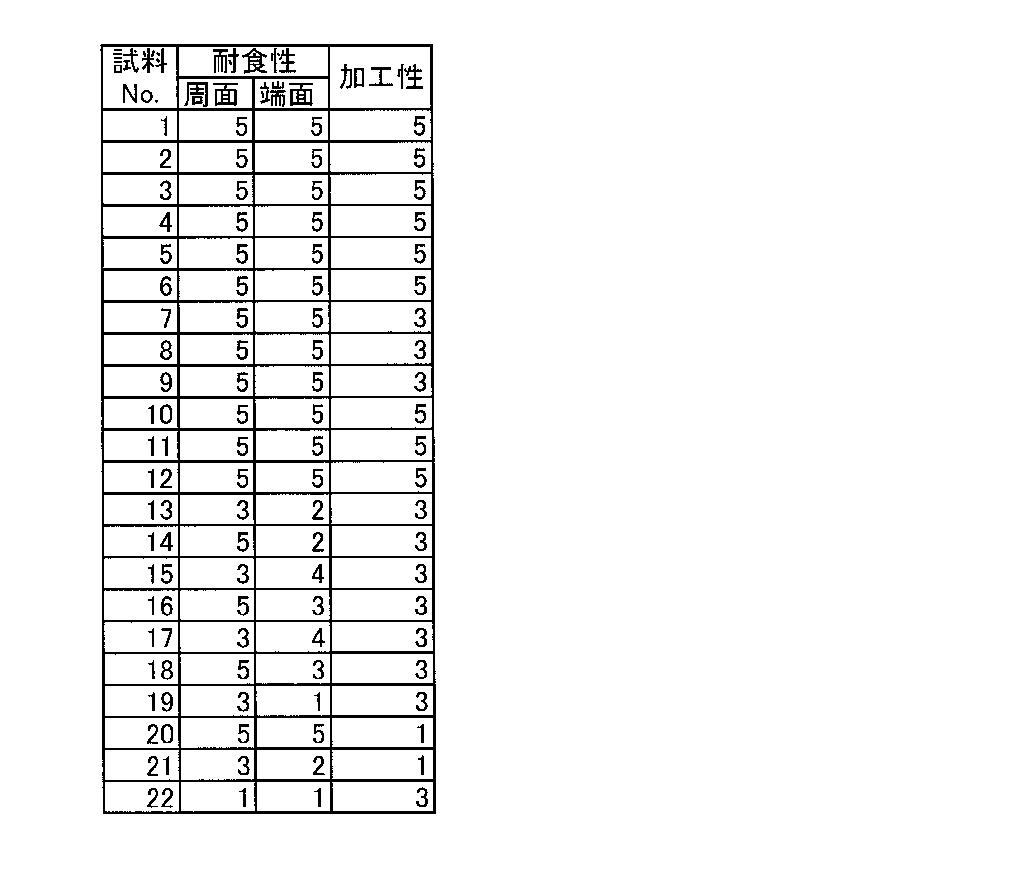
表2に示すように、試料No.1から試料No.18のAl基線材は、試料No.19から試料No.22に比較して、芯線の耐食性に優れると共に、加工性に優れることがわかる。中でも、試料No.1から試料No.12のAl基線材は、試料No.13から試料No.18に比較して、芯線の耐食性に優れる。特に、試料No.1から試料No.6,試料No.10から試料No.12は、試料No.7から試料No.9、試料No.13から試料No.18に比較して、加工性に優れる。
図5及び図6は、代表的に試料No.6のAl基線材における外周面の顕微鏡写真及び端面の顕微鏡写真を示す。一方、図8及び図9は、代表的に試料No.19のAl基線材における外周面の顕微鏡写真及び端面の顕微鏡写真を示す。各試料の外周面の顕微鏡写真は、直接観察像である。各試料の端面の顕微鏡写真は、反射電子像である。
試料No.6のAl基線材は、図5及び図6から、芯線の耐食性に優れることがわかる。図5に示すように、試料No.6における芯線の外周面は、被覆層で覆われていて被覆層から露出していないからである。また、図6に示すように、試料No.6における芯線の端面は、実質的に全面にわたって焦点が合っており、陥没箇所が実質的に形成されていないからである。即ち、試料No.6における芯線は、実質的に腐食していない。
一方、試料No.19のAl基線材は、図8及び図9から、芯線の耐食性に劣ることがわかる。図8に示すように、試料No.19における芯線の外周面は、被覆層が剥がれて露出しているからである。また、図9に示すように、試料No.19における芯線の端面は、焦点が合っていない箇所が複数あり、複数の陥没箇所が形成されているからである。即ち、試料No.19における芯線は、広範囲にわたって腐食している。
図7は、代表的に試料No.6のAl基線材をSUS線に巻き付けた状態の顕微鏡写真を示す。図7の紙面上下方向の中央に紙面左右方向に延びる部材がSUS線である。
試料No.6のAl基線材は、図7から、加工性に優れることがわかる。図7に示すように、試料No.6のAl基線材における被覆層の外周面は、実質的にクラックが発生していないからである。一方、図示は省略しているが、加工性に劣る試料No.20、No.21のAl基線材における被覆層の外周面には、複数のクラックが生じていた。具体的には、螺旋状に巻き付けたAl基線材の軸方向、即ちSUS線の長手方向に沿ったクラックなどが生じていた。
本発明は、これらの例示に限定されるものではなく、請求の範囲によって示され、請求の範囲と均等の意味および範囲内でのすべての変更が含まれることが意図される。
1 アルミニウム基線材、Al基線材
2 芯線
3 下地層
4 被覆層
41 第一層
42 第二層
420 分散組織
421 第一相
422 第二相
43 第三層
5 腐食生成物
2 芯線
3 下地層
4 被覆層
41 第一層
42 第二層
420 分散組織
421 第一相
422 第二相
43 第三層
5 腐食生成物
Claims (8)
- 純アルミニウム、又はアルミニウム合金からなる芯線と、
前記芯線の外周に設けられた被覆層とを備え、
前記被覆層は、
前記芯線の外周に設けられた第一層と、
前記第一層の外周に設けられた第二層と、
前記第二層の外周に設けられた第三層とを有し、
前記第一層は、ニッケル、鉄、コバルト、クロム、銅、銀、及びこれらの元素の合金からなる群より選択される少なくとも一種の金属から構成され、
前記第二層は、亜鉛とスズとを含む金属から構成され、
前記第三層は、スズ、及び実質的に亜鉛を含まないスズ合金からなる群より選択される少なくとも一種の金属から構成され、
前記第二層における亜鉛の含有量が、15原子%以上60原子%以下である、
アルミニウム基線材。 - 前記第二層の組織は、スズを主成分とする第一相中に亜鉛を主成分とする第二相が分散した分散組織を有し、
前記第二相の大きさが、0.01μm以上1μm以下である請求項1に記載のアルミニウム基線材。 - 前記第一層の厚みD1と前記第二層の厚みD2との比D2/D1が、5以上である請求項1又は請求項2に記載のアルミニウム基線材。
- 前記第一層の厚みD1が、0.05μm以上1μm以下である請求項1から請求項3のいずれか1項に記載のアルミニウム基線材。
- 前記第二層の厚みD2が、0.5μm以上である請求項1から請求項4のいずれか1項に記載のアルミニウム基線材。
- 前記第三層の厚みD3が、1.5μm以上である請求項1から請求項5のいずれか1項に記載のアルミニウム基線材。
- 前記芯線の直径が、0.01mm以上2mm以下である請求項1から請求項6のいずれか1項に記載のアルミニウム基線材。
- 前記芯線と前記被覆層との間に設けられた下地層を有し、
前記下地層は、亜鉛を主成分とする請求項1から請求項7のいずれか1項に記載のアルミニウム基線材。
Priority Applications (4)
| Application Number | Priority Date | Filing Date | Title |
|---|---|---|---|
| CN202080018946.4A CN113544315B (zh) | 2019-03-20 | 2020-03-17 | 铝基线材 |
| JP2021507379A JP7347495B2 (ja) | 2019-03-20 | 2020-03-17 | アルミニウム基線材 |
| US17/434,477 US11810691B2 (en) | 2019-03-20 | 2020-03-17 | Aluminum base wire |
| DE112020001364.2T DE112020001364T5 (de) | 2019-03-20 | 2020-03-17 | Draht auf Aluminiumbasis |
Applications Claiming Priority (2)
| Application Number | Priority Date | Filing Date | Title |
|---|---|---|---|
| JP2019-053850 | 2019-03-20 | ||
| JP2019053850 | 2019-03-20 |
Publications (1)
| Publication Number | Publication Date |
|---|---|
| WO2020189689A1 true WO2020189689A1 (ja) | 2020-09-24 |
Family
ID=72520142
Family Applications (1)
| Application Number | Title | Priority Date | Filing Date |
|---|---|---|---|
| PCT/JP2020/011822 Ceased WO2020189689A1 (ja) | 2019-03-20 | 2020-03-17 | アルミニウム基線材 |
Country Status (5)
| Country | Link |
|---|---|
| US (1) | US11810691B2 (ja) |
| JP (1) | JP7347495B2 (ja) |
| CN (1) | CN113544315B (ja) |
| DE (1) | DE112020001364T5 (ja) |
| WO (1) | WO2020189689A1 (ja) |
Cited By (1)
| Publication number | Priority date | Publication date | Assignee | Title |
|---|---|---|---|---|
| US12573778B2 (en) * | 2021-02-24 | 2026-03-10 | Autonetworks Technologies, Ltd. | Metal material, connection terminal and metal material manufacturing method |
Families Citing this family (1)
| Publication number | Priority date | Publication date | Assignee | Title |
|---|---|---|---|---|
| CN120330686A (zh) * | 2023-08-01 | 2025-07-18 | 余乐华 | 一种镀锡铝合金导体材料及其制备方法、应用 |
Citations (5)
| Publication number | Priority date | Publication date | Assignee | Title |
|---|---|---|---|---|
| JPS5057036A (ja) * | 1973-09-20 | 1975-05-19 | ||
| JPS54144992A (en) * | 1978-05-04 | 1979-11-12 | Shiroyama Seisakusho Kk | Zinc and tin coated aluminium conductor |
| JP2006219736A (ja) * | 2005-02-14 | 2006-08-24 | Toyo Kohan Co Ltd | 表面処理Al板 |
| JP2010157416A (ja) * | 2008-12-26 | 2010-07-15 | Sumitomo Electric Ind Ltd | アルミニウム合金線 |
| JP2013007092A (ja) * | 2011-06-24 | 2013-01-10 | Fukuda Metal Foil & Powder Co Ltd | 多層めっきアルミニウム又はアルミニウム合金箔 |
Family Cites Families (11)
| Publication number | Priority date | Publication date | Assignee | Title |
|---|---|---|---|---|
| US3867265A (en) * | 1971-03-29 | 1975-02-18 | Ericsson Telefon Ab L M | Process for electroplating an aluminum wire |
| JPS5846540B2 (ja) * | 1979-07-23 | 1983-10-17 | 住友軽金属工業株式会社 | 非酸化性減圧雰囲気ろう付けにより組立てられる熱交換器用アルミニウム合金合せ材 |
| JPH11181593A (ja) * | 1997-12-16 | 1999-07-06 | Totoku Electric Co Ltd | 銅被覆アルミニウム線の製造方法 |
| FR2876493B1 (fr) * | 2004-10-12 | 2007-01-12 | F S P One Soc Par Actions Simp | Cable toronne en aluminium cuivre, et procede pour sa fabrication. |
| FR2881870B1 (fr) * | 2005-02-10 | 2011-10-21 | Nexans | Fil electrique a ame en aluminium ou alliage d'aluminium |
| SE534283C2 (sv) * | 2009-05-14 | 2011-06-28 | Sapa Heat Transfer Ab | Lodpläterad aluminiumplåt för tunna rör |
| CN104981346B (zh) * | 2013-02-12 | 2017-07-18 | 塔塔钢铁艾默伊登有限责任公司 | 适于热浸镀锌的涂覆钢基材 |
| CN103871597B (zh) * | 2014-02-25 | 2016-08-03 | 安徽绿洲电缆有限公司 | 一种海底专用电力电缆 |
| CN104124006B (zh) * | 2014-08-15 | 2016-08-24 | 国网山东省电力公司莱芜供电公司 | 一种单绞线电缆的制备方法 |
| CN104361942B (zh) * | 2014-11-28 | 2016-08-24 | 国家电网公司 | 一种单绞线铝合金芯电缆及其制备方法 |
| JP6783731B2 (ja) | 2017-09-13 | 2020-11-11 | トヨタ自動車株式会社 | 硫化物固体電解質 |
-
2020
- 2020-03-17 DE DE112020001364.2T patent/DE112020001364T5/de active Pending
- 2020-03-17 WO PCT/JP2020/011822 patent/WO2020189689A1/ja not_active Ceased
- 2020-03-17 US US17/434,477 patent/US11810691B2/en active Active
- 2020-03-17 CN CN202080018946.4A patent/CN113544315B/zh active Active
- 2020-03-17 JP JP2021507379A patent/JP7347495B2/ja active Active
Patent Citations (5)
| Publication number | Priority date | Publication date | Assignee | Title |
|---|---|---|---|---|
| JPS5057036A (ja) * | 1973-09-20 | 1975-05-19 | ||
| JPS54144992A (en) * | 1978-05-04 | 1979-11-12 | Shiroyama Seisakusho Kk | Zinc and tin coated aluminium conductor |
| JP2006219736A (ja) * | 2005-02-14 | 2006-08-24 | Toyo Kohan Co Ltd | 表面処理Al板 |
| JP2010157416A (ja) * | 2008-12-26 | 2010-07-15 | Sumitomo Electric Ind Ltd | アルミニウム合金線 |
| JP2013007092A (ja) * | 2011-06-24 | 2013-01-10 | Fukuda Metal Foil & Powder Co Ltd | 多層めっきアルミニウム又はアルミニウム合金箔 |
Cited By (1)
| Publication number | Priority date | Publication date | Assignee | Title |
|---|---|---|---|---|
| US12573778B2 (en) * | 2021-02-24 | 2026-03-10 | Autonetworks Technologies, Ltd. | Metal material, connection terminal and metal material manufacturing method |
Also Published As
| Publication number | Publication date |
|---|---|
| DE112020001364T5 (de) | 2021-12-02 |
| JP7347495B2 (ja) | 2023-09-20 |
| CN113544315A (zh) | 2021-10-22 |
| US20220139593A1 (en) | 2022-05-05 |
| JPWO2020189689A1 (ja) | 2020-09-24 |
| US11810691B2 (en) | 2023-11-07 |
| CN113544315B (zh) | 2023-09-29 |
Similar Documents
| Publication | Publication Date | Title |
|---|---|---|
| JP6560455B2 (ja) | 表面処理材及びその製造方法、並びにこの表面処理材を用いて作製した部品 | |
| JP6452912B1 (ja) | めっき線棒材及びその製造方法、並びにこれを用いて形成されたケーブル、電線、コイル及びばね部材 | |
| JP6279170B1 (ja) | 表面処理材およびその製造方法ならびに表面処理材を用いて形成した部品 | |
| JP7415287B2 (ja) | アルミニウム基線材、撚り線、及びアルミニウム基線材の製造方法 | |
| JP7347495B2 (ja) | アルミニウム基線材 | |
| JP2011042860A (ja) | アルミニウム製導電部材との接続に用いられる接続部品用錫めっき付銅又は銅合金材料 | |
| CN102834877B (zh) | 汽车用电线 | |
| WO2022123818A1 (ja) | Ag被覆素材、Ag被覆素材の製造方法及び端子部品 | |
| JP6655769B1 (ja) | めっき線棒、当該めっき線棒の製造方法、並びに、当該めっき線棒を用いた、ケーブル、電線、コイル、ワイヤハーネス、ばね部材、エナメル線、及び、リード線 | |
| WO2019102978A1 (ja) | アルミニウム系素線、撚線導体、編組線、および、ワイヤーハーネス | |
| CN110121575A (zh) | 表面处理材料及使用该表面处理材料制作的零件 | |
| JP7469295B2 (ja) | 複合部材、及び放熱部材 | |
| US12428732B2 (en) | Metal material and method for manufacturing metal material | |
| JP2020056090A (ja) | 防食端子材とその製造方法、及び防食端子並びに電線端末部構造 | |
| WO2023047854A1 (ja) | 線材および線材の製造方法 | |
| US7491890B2 (en) | Electric wire having a core of aluminum or aluminum alloy | |
| JP2010126805A (ja) | 表面処理金属材およびその製造方法 | |
| JP2022114347A (ja) | 複合線、及び被覆線 | |
| JPH0210525B2 (ja) | ||
| JP2010165528A (ja) | アルミニウム合金線 | |
| JP2001135148A (ja) | 高耐食性架空送電線 |
Legal Events
| Date | Code | Title | Description |
|---|---|---|---|
| 121 | Ep: the epo has been informed by wipo that ep was designated in this application |
Ref document number: 20772648 Country of ref document: EP Kind code of ref document: A1 |
|
| ENP | Entry into the national phase |
Ref document number: 2021507379 Country of ref document: JP Kind code of ref document: A |
|
| 122 | Ep: pct application non-entry in european phase |
Ref document number: 20772648 Country of ref document: EP Kind code of ref document: A1 |