WO2020189616A1 - バルブタイミング調整装置 - Google Patents
バルブタイミング調整装置 Download PDFInfo
- Publication number
- WO2020189616A1 WO2020189616A1 PCT/JP2020/011394 JP2020011394W WO2020189616A1 WO 2020189616 A1 WO2020189616 A1 WO 2020189616A1 JP 2020011394 W JP2020011394 W JP 2020011394W WO 2020189616 A1 WO2020189616 A1 WO 2020189616A1
- Authority
- WO
- WIPO (PCT)
- Prior art keywords
- valve timing
- shaft
- sprocket
- driven
- rotating body
- Prior art date
- Legal status (The legal status is an assumption and is not a legal conclusion. Google has not performed a legal analysis and makes no representation as to the accuracy of the status listed.)
- Ceased
Links
Images


Classifications
-
- F—MECHANICAL ENGINEERING; LIGHTING; HEATING; WEAPONS; BLASTING
- F01—MACHINES OR ENGINES IN GENERAL; ENGINE PLANTS IN GENERAL; STEAM ENGINES
- F01L—CYCLICALLY OPERATING VALVES FOR MACHINES OR ENGINES
- F01L1/00—Valve-gear or valve arrangements, e.g. lift-valve gear
- F01L1/34—Valve-gear or valve arrangements, e.g. lift-valve gear characterised by the provision of means for changing the timing of the valves without changing the duration of opening and without affecting the magnitude of the valve lift
- F01L1/344—Valve-gear or valve arrangements, e.g. lift-valve gear characterised by the provision of means for changing the timing of the valves without changing the duration of opening and without affecting the magnitude of the valve lift changing the angular relationship between crankshaft and camshaft, e.g. using helicoidal gear
- F01L1/356—Valve-gear or valve arrangements, e.g. lift-valve gear characterised by the provision of means for changing the timing of the valves without changing the duration of opening and without affecting the magnitude of the valve lift changing the angular relationship between crankshaft and camshaft, e.g. using helicoidal gear making the angular relationship oscillate, e.g. non-homokinetic drive
-
- F—MECHANICAL ENGINEERING; LIGHTING; HEATING; WEAPONS; BLASTING
- F01—MACHINES OR ENGINES IN GENERAL; ENGINE PLANTS IN GENERAL; STEAM ENGINES
- F01L—CYCLICALLY OPERATING VALVES FOR MACHINES OR ENGINES
- F01L1/00—Valve-gear or valve arrangements, e.g. lift-valve gear
- F01L1/34—Valve-gear or valve arrangements, e.g. lift-valve gear characterised by the provision of means for changing the timing of the valves without changing the duration of opening and without affecting the magnitude of the valve lift
- F01L1/344—Valve-gear or valve arrangements, e.g. lift-valve gear characterised by the provision of means for changing the timing of the valves without changing the duration of opening and without affecting the magnitude of the valve lift changing the angular relationship between crankshaft and camshaft, e.g. using helicoidal gear
- F01L1/352—Valve-gear or valve arrangements, e.g. lift-valve gear characterised by the provision of means for changing the timing of the valves without changing the duration of opening and without affecting the magnitude of the valve lift changing the angular relationship between crankshaft and camshaft, e.g. using helicoidal gear using bevel or epicyclic gear
-
- F—MECHANICAL ENGINEERING; LIGHTING; HEATING; WEAPONS; BLASTING
- F16—ENGINEERING ELEMENTS AND UNITS; GENERAL MEASURES FOR PRODUCING AND MAINTAINING EFFECTIVE FUNCTIONING OF MACHINES OR INSTALLATIONS; THERMAL INSULATION IN GENERAL
- F16H—GEARING
- F16H1/00—Toothed gearings for conveying rotary motion
- F16H1/28—Toothed gearings for conveying rotary motion with gears having orbital motion
- F16H1/32—Toothed gearings for conveying rotary motion with gears having orbital motion in which the central axis of the gearing lies inside the periphery of an orbital gear
-
- H—ELECTRICITY
- H02—GENERATION; CONVERSION OR DISTRIBUTION OF ELECTRIC POWER
- H02K—DYNAMO-ELECTRIC MACHINES
- H02K7/00—Arrangements for handling mechanical energy structurally associated with dynamo-electric machines, e.g. structural association with mechanical driving motors or auxiliary dynamo-electric machines
- H02K7/06—Means for converting reciprocating motion into rotary motion or vice versa
-
- F—MECHANICAL ENGINEERING; LIGHTING; HEATING; WEAPONS; BLASTING
- F01—MACHINES OR ENGINES IN GENERAL; ENGINE PLANTS IN GENERAL; STEAM ENGINES
- F01L—CYCLICALLY OPERATING VALVES FOR MACHINES OR ENGINES
- F01L1/00—Valve-gear or valve arrangements, e.g. lift-valve gear
- F01L1/02—Valve drive
- F01L1/04—Valve drive by means of cams, camshafts, cam discs, eccentrics or the like
- F01L1/047—Camshafts
- F01L2001/0476—Camshaft bearings
-
- F—MECHANICAL ENGINEERING; LIGHTING; HEATING; WEAPONS; BLASTING
- F01—MACHINES OR ENGINES IN GENERAL; ENGINE PLANTS IN GENERAL; STEAM ENGINES
- F01L—CYCLICALLY OPERATING VALVES FOR MACHINES OR ENGINES
- F01L13/00—Modifications of valve-gear to facilitate reversing, braking, starting, changing compression ratio, or other specific operations
- F01L2013/10—Auxiliary actuators for variable valve timing
- F01L2013/103—Electric motors
-
- F—MECHANICAL ENGINEERING; LIGHTING; HEATING; WEAPONS; BLASTING
- F01—MACHINES OR ENGINES IN GENERAL; ENGINE PLANTS IN GENERAL; STEAM ENGINES
- F01L—CYCLICALLY OPERATING VALVES FOR MACHINES OR ENGINES
- F01L2303/00—Manufacturing of components used in valve arrangements
-
- F—MECHANICAL ENGINEERING; LIGHTING; HEATING; WEAPONS; BLASTING
- F16—ENGINEERING ELEMENTS AND UNITS; GENERAL MEASURES FOR PRODUCING AND MAINTAINING EFFECTIVE FUNCTIONING OF MACHINES OR INSTALLATIONS; THERMAL INSULATION IN GENERAL
- F16H—GEARING
- F16H1/00—Toothed gearings for conveying rotary motion
- F16H1/28—Toothed gearings for conveying rotary motion with gears having orbital motion
- F16H1/32—Toothed gearings for conveying rotary motion with gears having orbital motion in which the central axis of the gearing lies inside the periphery of an orbital gear
- F16H2001/323—Toothed gearings for conveying rotary motion with gears having orbital motion in which the central axis of the gearing lies inside the periphery of an orbital gear comprising eccentric crankshafts driving or driven by a gearing
Definitions
- This disclosure relates to a valve timing adjusting device.
- an electric valve timing adjusting device capable of adjusting the valve timing of the intake valve and the exhaust valve of an internal combustion engine has been known.
- a plurality of rollers are arranged between an eccentric shaft portion to which a rotational force is input from an electric actuator and a plurality of internal teeth formed on a driving rotating body.
- a deceleration mechanism is used in which a rotational force is output from a cage that regulates the movement of a plurality of rollers in the circumferential direction.
- a plurality of internal teeth are formed on the inner peripheral surface of the driving rotating body, and a sprocket portion for transmitting power from the driving shaft is formed on the outer peripheral surface of the driving rotating body.
- the sprocket portion may be formed with a different shape, size, number of teeth, or the like, depending on the specifications of the internal combustion engine.
- the drive rotating body including a plurality of internal teeth is formed differently according to the specifications of the internal combustion engine, the assembly process of the valve timing adjusting device may be complicated. Therefore, a technique capable of suppressing an increase in the cost required for manufacturing the valve timing adjusting device is desired.
- a valve timing adjusting device is provided.
- This valve timing adjusting device is arranged at the axial end of the driven shaft in which power is transmitted from the driving shaft in the internal combustion engine, and adjusts the valve timing of the valve driven to open and close by the driven shaft.
- Cylindrical eccentricity formed by having a drive rotating body that rotates around the rotation axis in conjunction with the drive axis and the outer peripheral surface of the drive rotating body that is rotationally driven by an actuator and is eccentric to the rotation axis.
- a plurality of plurality of internal teeth arranged side by side in the circumferential direction between the shaft portion and the plurality of internal teeth and the eccentric shaft portion in a radial direction orthogonal to the axial direction, and a number smaller than the number of teeth of the plurality of internal teeth. It has a roller, a cage that regulates the movement of the plurality of rollers in the circumferential direction, and a stopper portion that defines a limit of the relative rotation phase of the driven shaft with respect to the drive shaft, and is interlocked with the driven shaft.
- a driven rotating body that rotates about the center of rotation, and a cover portion that is arranged outside the stopper portion in the radial direction and has an engaging portion that engages with the stopper portion in the circumferential direction.
- the housing portion is formed with a press-fitting portion that is press-fitted into the inner peripheral surface of the sprocket portion.
- the sprocket portion and the housing portion are formed as separate bodies, the sprocket portion that can be designed according to the specifications of the internal combustion engine and the accuracy as a reduction mechanism are required.
- the housing portion on which a plurality of internal teeth are formed can be formed separately, and the housing portion can be used as a common component regardless of the specifications of the internal combustion engine. Therefore, it is possible to suppress an increase in the cost required for manufacturing the drive rotating body.
- the press-fitting portion to be press-fitted onto the inner peripheral surface of the sprocket portion is formed in the housing portion, the press-fitting portion is formed after assembling the eccentric shaft portion, a plurality of rollers, and the driven rotating body to the housing portion.
- the sprocket portion and the housing portion can be fixed to each other by press-fitting into the inner peripheral surface of the sprocket portion. Therefore, regardless of the specifications of the internal combustion engine, the process before assembling the sprocket portion can be standardized, and the assembling process of the valve timing adjusting device can be suppressed from becoming complicated. Therefore, it is possible to suppress an increase in the cost required for manufacturing the valve timing adjusting device.
- This disclosure can also be realized in various forms. For example, it can be realized in the form of a method for manufacturing a valve timing adjusting device, an internal combustion engine provided with the valve timing adjusting device, a vehicle provided with such an internal combustion engine, or the like.
- FIG. 1 is a cross-sectional view showing a schematic configuration of the valve timing adjusting device of the first embodiment.
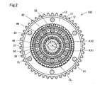
- FIG. 2 is a cross-sectional view showing a cross section taken along the line II-II of FIG.
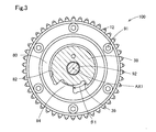
- FIG. 3 is a cross-sectional view showing a cross section taken along the line III-III of FIG.
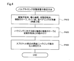
- FIG. 4 is a process diagram showing the procedure of the manufacturing method of the valve timing adjusting device.
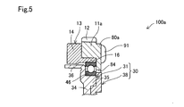
- FIG. 5 is a schematic cross-sectional view schematically showing the configuration of the main part in the second embodiment.
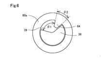
- FIG. 6 is an explanatory view showing the extension angle of the engaging portion in the circumferential direction.
- FIG. 7 is an explanatory view showing an extension angle of the engaging portion in the circumferential direction.
- the valve timing adjusting device 100 of the present embodiment is fastened to the end of the cam shaft 220 in the direction along the rotation axis AX1 of the cam shaft 220 (hereinafter, also referred to as “axial direction AD”), and takes in air as a valve.
- valve and the exhaust valve adjust the valve timing of the intake valve.
- the side and direction in which the camshaft 220 is provided with respect to the valve timing adjusting device 100 in the axial direction AD are also referred to as "rear side", and the side and direction opposite to the rear side in the axial direction AD. Is also called the "front side”.
- the valve timing adjusting device 100 is driven by an electric actuator (not shown) connected to the front side.
- an electric actuator is controlled by an ECU (not shown) that controls the overall operation of the internal combustion engine 200.
- the valve timing adjusting device 100 includes a drive rotating body 10, an eccentric shaft portion 20, a driven rotating body 30, a plurality of rollers 60, a cover portion 80, and a small diameter bearing 42. , A needle bearing 44, a large diameter bearing 46, and a medium diameter bearing 48.
- the drive rotating body 10 rotates around the rotation axis AX1 of the cam shaft 220 in conjunction with the crankshaft 210.
- the drive rotating body 10 has a sprocket portion 11 arranged in order from the rear side, a housing portion 13, and a front cover 18.
- the sprocket portion 11, the housing portion 13, and the front cover 18 are fastened by a plurality of bolts 91.
- the sprocket portion 11 has a substantially annular appearance shape, and a plurality of gear portions 12 are formed on the outer peripheral surface.
- a timing chain 215 is hung between the gear portion 12 and the gear 212 formed on the crankshaft 210.
- the drive rotating body 10 rotates in conjunction with the crankshaft 210.
- a timing belt or the like may be used instead of the timing chain 215.
- the shape and size of the sprocket portion 11 and the number of teeth of the gear portion 12 can be designed according to the specifications of the internal combustion engine 200.
- the housing portion 13 has a substantially tubular external shape.
- the housing portion 13 has an annular portion 14 and a press-fit portion 16.
- a plurality of internal teeth 15 are formed on the inner peripheral surface of the annular portion 14.
- the press-fitting portion 16 is formed so as to project from the annular portion 14 toward the rear side.
- the press-fitting portion 16 has a cylindrical appearance shape along the axial direction AD, and is press-fitted into the inner peripheral surface of the sprocket portion 11.
- the front cover 18 has a disk-shaped external shape.
- An opening 19 is formed substantially in the center of the front cover.
- An eccentric shaft portion 20 is inserted into the opening portion 19.
- the eccentric shaft portion 20 has a substantially cylindrical external shape, is connected to an output shaft (not shown) of the electric actuator, and is rotationally driven around the rotary shaft center AX1.
- the outer peripheral surface on the rear side is formed eccentrically with respect to the rotation axis AX1.
- the axial center on the outer peripheral surface is also referred to as an eccentric axial center AX2.
- the driven rotating body 30 rotates around the rotation axis AX1 in conjunction with the cam shaft 220.
- the driven rotating body 30 is fastened to the end of the cam shaft 220 in the axial direction AD by the center bolt 92, and is configured to be rotatable relative to the driving rotating body 10.
- the driven rotating body 30 has a main body portion 31 and a plate portion 38.
- the main body portion 31 has a tubular portion 32, a plate-shaped portion 34, a bearing portion 35, and a cage 36.
- the tubular portion 32 has a substantially cylindrical appearance shape, and is arranged inside the eccentric shaft portion 20 in the radial direction.
- a small diameter bearing 42 and a needle bearing 44 are interposed side by side from the front side between the outer peripheral surface of the tubular portion 32 and the inner peripheral surface of the eccentric shaft portion 20.
- the eccentric shaft portion 20 is rotatably supported with respect to the tubular portion 32 by the small diameter bearing 42 and the needle bearing 44.
- a shaft hole 33 along the rotation axis AX1 is formed in the tubular portion 32.
- a center bolt 92 is inserted into the shaft hole 33.
- the plate-shaped portion 34 has a substantially disk-like appearance shape that is connected to the rear end of the tubular portion 32 and is formed toward the outer side in the radial direction.
- the bearing portion 35 is formed so as to project from the plate-shaped portion 34 to the rear side in an annular shape.
- a large-diameter bearing 46 is interposed between the outer peripheral surface of the bearing portion 35 and the inner peripheral surface of the press-fitting portion 16 of the housing portion 13.
- the cage 36 has a substantially cylindrical appearance shape that is connected to the outer edge of the plate-shaped portion 34 in the radial direction and is formed toward the front side.
- the cage 36 is inserted between the inner peripheral surface of the housing portion 13 of the drive rotating body 10 and the outer peripheral surface of the medium-diameter bearing 48.
- the medium-diameter bearing 48 is arranged on the outer peripheral surface of the eccentric shaft portion 20 centered on the eccentric shaft center AX2.
- a plurality of roller holding holes 37 are formed in the cage 36 at equal intervals along the circumferential direction.
- the plurality of roller holding holes 37 are each formed in a substantially rectangular shape when viewed in the radial direction, and hold the plurality of rollers 60 so as to be rollable.
- the number of the plurality of roller holding holes 37 is smaller than the number of internal teeth 15 formed in the housing portion 13 of the drive rotating body 10.
- the cage 36 has a function of restricting the movement of the plurality of rollers 60 in the circumferential direction and outputting a rotational force to the cam shaft 220.
- the plate portion 38 has a substantially disk-like appearance shape, and is arranged in contact with the rear end surface of the plate-shaped portion 34.
- the plate portion 38 is formed separately from the main body portion 31 and bolted by the center bolt 92, but may be integrally formed with the main body portion 31.
- a stopper portion 39 is formed on the outer edge of the plate portion 38 in the radial direction.
- the stopper portion 39 is formed so as to be recessed inward in the radial direction in a part in the circumferential direction.
- the stopper portion 39 defines a limit on the relative rotation phase of the camshaft 220 with respect to the crankshaft 210, as will be described later.
- the plurality of rollers 60 are arranged at equal intervals between the inner peripheral surface of the housing portion 13 of the drive rotating body 10 and the outer peripheral surface of the medium-diameter bearing 48. As described above, the plurality of rollers 60 are arranged side by side in the circumferential direction between the plurality of internal teeth 15 and the eccentric shaft portion 20 in the radial direction. In the present embodiment, the number of the plurality of rollers 60 is smaller than the number of internal teeth 15 formed in the housing portion 13 of the drive rotating body 10, and is the same as the number of the plurality of roller holding holes 37.
- Each roller 60 is arranged in each roller holding hole 37 formed in the cage 36 of the driven rotating body 30, and is held in the cage 36 in a state where the movement in the radial direction is permitted.
- Each roller 60 is always in contact with the outer peripheral surface of the medium diameter bearing 48.
- a crescent ring-shaped gap CL is formed on the outer side of the medium-diameter bearing 48 in the radial direction in a part in the circumferential direction.
- the medium-diameter bearing 48 is configured to be movable in the radial direction, that is, to be eccentric, as the eccentric shaft portion 20 rotates eccentrically through the gap CL.
- Each roller 60 swings in the radial direction while being guided by the cage 36 with the eccentric movement of the medium-diameter bearing 48, and a part of the plurality of rollers 60 is formed in the housing portion 13. It fits in a part of.
- the cover portion 80 shown in FIGS. 1 and 3 has a substantially disk-like external shape, and is arranged in contact with the rear end surface of the sprocket portion 11 and the rear end surface of the large diameter bearing 46. ..
- the cover portion 80 is fastened to the drive rotating body 10 by a plurality of bolts 91.
- An opening 82 is formed substantially in the center of the cover portion 80.
- a plate portion 38 of the driven rotating body 30 is arranged in the opening 82. Therefore, the cover portion 80 is arranged on the outer side in the radial direction with respect to the stopper portion 39.
- the opening 82 is formed with an engaging portion 84 that projects inward in the radial direction in a part of the circumferential direction.
- the engaging portion 84 is extended along the circumferential direction at a predetermined extension angle.
- the engaging portion 84 engages in the circumferential direction with the stopper portion 39 that defines the limit of the relative rotation phase of the cam shaft 220 with respect to the crank shaft 210. Therefore, the phase change angle ⁇ 1 is defined by the engaging portion 84 and the stopper portion 39.
- the cover portion 80 has a function of pressing the large-diameter bearing 46 in the axial direction AD and a function of defining the phase change angle ⁇ 1.
- each roller 60 is guided by the cage 36 and the internal teeth formed in the housing portion 13 are formed. It overcomes 15 and moves along the circumferential direction while rolling to the adjacent internal tooth 15.
- the rotation speed of the eccentric shaft portion 20 is decelerated and transmitted to the driven rotating body 30, and the relative rotation phase of the driven rotating body 30 with respect to the driven rotating body 10 is changed.
- the phase of the cam shaft 220 with respect to the crank shaft 210 is changed, and valve timing corresponding to such a phase is realized.
- crankshaft 210 corresponds to the subordinate concept of the drive shaft in the present disclosure
- camshaft 220 corresponds to the subordinate concept of the driven shaft in the present disclosure
- A-2. Manufacturing method of valve timing adjustment device In the method of manufacturing the valve timing adjusting device 100 shown in FIG. 4, a drive rotating body 10 having the above configuration, an eccentric shaft portion 20, a driven rotating body 30, a plurality of rollers 60, a cover portion 80, and bearings are used. 42, 44, 46, 48 are prepared (step P410). Step P410 is also referred to as a preparatory step. In the preparatory step, the sprocket portion 11 and the housing portion 13 of the drive rotating body 10 are formed separately.
- step P420 Assemble the eccentric shaft portion 20, the plurality of rollers 60, and the driven rotating body 30 to the housing portion 13 (process P420).
- a large-diameter bearing 46 is arranged between the inner peripheral surface of the press-fitting portion 16 formed in the housing portion 13 and the outer peripheral surface of the bearing portion 35 formed in the driven rotating body 30. The large diameter bearing 46 is held by the press-fitting portion 16.
- the press-fitting portion 16 of the housing portion 13 is press-fitted into the inner peripheral surface of the sprocket portion 11 to fix the sprocket portion 11 and the housing portion 13 to each other (process P430).
- the cover portion 80 is fastened to the drive rotating body 10 by a plurality of bolts 91, and the production of the valve timing adjusting device 100 is completed.
- the sprocket portion 11 and the housing portion 13 are formed as separate bodies. Therefore, a sprocket portion 11 in which the shape and size, the number of teeth of the gear portion 12, and the like can be designed according to the specifications of the internal combustion engine 200, and a plurality of internal teeth 15 that require accuracy as a reduction mechanism are formed. Since the housing portion 13 is formed as a separate body, the housing portion 13 can be a common component regardless of the specifications of the internal combustion engine 200, and it is possible to suppress an increase in the cost required for manufacturing the drive rotating body 10. ..
- the entire drive rotating body 10 including the plurality of internal teeth 15 that require accuracy is formed differently according to the specifications of the internal combustion engine 200. This increases the cost required for manufacturing the drive rotating body 10.
- valve timing adjusting device 100 of the present embodiment since the sprocket portion 11 and the housing portion 13 are formed as separate bodies, it is possible to suppress an increase in the cost required for manufacturing the drive rotating body 10. In addition, it is possible to suppress a decrease in the degree of freedom in designing the timing chain 215 and the gear portion 12.
- the housing portion 13 is formed with the press-fitting portion 16 to be press-fitted into the inner peripheral surface of the sprocket portion 11, the eccentric shaft portion 20, the plurality of rollers 60, and the driven rotating body 30 are attached to the housing portion 13.
- the press-fitting portion 16 can be press-fitted into the inner peripheral surface of the sprocket portion 11 to fix the sprocket portion 11 and the housing portion 13 to each other. Therefore, regardless of the specifications of the internal combustion engine 200, the steps before assembling the sprocket portion 11 can be standardized. Therefore, it is possible to prevent the assembly process of the valve timing adjusting device 100 from becoming complicated.
- valve timing adjusting device 100 Therefore, it is possible to suppress an increase in the cost required for manufacturing the valve timing adjusting device 100.
- the valve timing adjusting device 100a of the second embodiment shown in FIGS. 5 to 7 is the first in that the sprocket portion 11a and the cover portion 80a, which were formed as separate bodies in the first embodiment, are integrally formed. It is different from the valve timing adjusting device 100 of one embodiment. Since the other configurations are the same as those in the first embodiment, the same configurations are designated by the same reference numerals, and detailed description thereof will be omitted.
- FIG. 5 a part of the housing portion 13, the sprocket portion 11a, the cover portion 80a, the large diameter bearing 46, and the driven rotating body 30 in the same cross section as in FIG. 1 is enlarged as the main parts of the valve timing adjusting device 100a. It is shown schematically. Further, in FIGS. 6 and 7, a cross section similar to that in FIG. 3 is schematically shown.
- the cover portion 80a in the second embodiment is configured as a single member having both the function of the sprocket portion 11a and the function of the engaging portion 84.
- the extension angle ⁇ 2 in the circumferential direction of the engaging portion 84 formed in the cover portion 80a is formed according to the specifications of the internal combustion engine 200.
- the phase change angle ⁇ 1 according to the specifications of the internal combustion engine 200 is defined.
- the fact that the extension angle ⁇ 2 is formed according to the specifications of the internal combustion engine 200 may be described in, for example, the specifications and the instruction manual of the valve timing adjusting device 100a.
- valve timing adjusting device 100a of the second embodiment the same effect as that of the valve timing adjusting device 100 of the first embodiment is obtained.
- the sprocket portion 11a is integrally formed with the cover portion 80a, the number of parts can be reduced and the assembly process can be simplified.
- the extension angle ⁇ 2 in the circumferential direction of the engaging portion 84 is formed according to the specifications of the internal combustion engine 200, the circumferential angle of the stopper portion 39 can be made the same regardless of the specifications of the internal combustion engine 200.
- the plate portion 38 can be a common component regardless of the specifications of the internal combustion engine 200.
- both the sprocket portion 11a and the engaging portion 84 which can be formed according to the specifications of the internal combustion engine 200, are formed in the cover portion 80a, other parts other than the cover portion 80a can be shared, and the valve can be shared. The increase in cost required for manufacturing the timing adjusting device 100a can be further suppressed.
- the engaging portion 84 is formed along the circumferential direction at an extension angle ⁇ 2 according to the specifications of the internal combustion engine 200, but is the same regardless of the specifications of the internal combustion engine 200. It may be a formed aspect.
- the phase change angle ⁇ 1 may be defined by forming the circumferential angle of the stopper portion 39 according to the specifications of the internal combustion engine 200. Even with such a configuration, the same effect as that of the second embodiment can be obtained.
- valve timing adjusting devices 100 and 100a in each of the above embodiments are merely examples and can be changed in various ways.
- the stopper portion 39 is formed to be recessed inward in the radial direction
- the engaging portion 84 is formed to project inward in the radial direction
- the stopper portion 39 is formed to be radially outward. It may be formed so as to project toward the outside, and the engaging portion 84 may be formed so as to be recessed toward the outside in the radial direction.
- the members instead of fastening the bolt 91 and the center bolt 92, the members may be fixed to each other by welding or the like. Even with such a configuration, the same effect as that of each of the above-described embodiments can be obtained.
- valve timing adjusting devices 100 and 100a in each of the above embodiments adjust the valve timing of the intake valve that the camshaft 220 opens and closes
- the valve timing of the exhaust valve may be adjusted.
- the valve timing adjusting devices 100 and 100a may be arranged and used at the end of the camshaft 220 as a driven shaft in which power is transmitted from the crankshaft 210 as a drive shaft via an intermediate shaft. It may be arranged and used at the end of the crankshaft 210, or may be arranged and used at one end of the drive shaft and the driven shaft provided in the dual structure camshaft.
- the present disclosure is not limited to each of the above-described embodiments, and can be realized with various configurations within a range not deviating from the purpose.
- the technical features in each embodiment corresponding to the technical features in the embodiments described in the column of the outline of the invention may be used to solve some or all of the above-mentioned problems, or one of the above-mentioned effects. It is possible to replace or combine as appropriate to achieve a part or all. Further, if the technical feature is not described as essential in the present specification, it can be appropriately deleted.
Landscapes
- Engineering & Computer Science (AREA)
- General Engineering & Computer Science (AREA)
- Mechanical Engineering (AREA)
- Power Engineering (AREA)
- Valve Device For Special Equipments (AREA)
- Retarders (AREA)
- Connection Of Motors, Electrical Generators, Mechanical Devices, And The Like (AREA)
Abstract
バルブタイミング調整装置(100、100a)は、駆動軸(210)から動力が伝達されるスプロケット部(11、11a)とスプロケット部とは別体に形成されて複数の内歯(15)が形成されたハウジング部(13)とを有する駆動回転体(10)と、偏心軸部(20)と、複数の内歯と偏心軸部との間に周方向に並んで配置された複数のローラ(60)と、複数のローラの周方向の移動を規制する保持器(36)とストッパ部(39)とを有し従動軸と連動して回転する従動回転体(30)と、ストッパ部に対して径方向の外側に配置されストッパ部と周方向に係合する係合部(84)が形成されたカバー部(80、80a)とを備え、ハウジング部には、スプロケット部の内周面に圧入される圧入部(16)が形成されている。
Description
本出願は、2019年3月18日に出願された日本出願番号2019-49314号に基づくもので、ここにその記載内容を援用する。
本開示は、バルブタイミング調整装置に関する。
従来から、内燃機関の吸気バルブや排気バルブのバルブタイミングを調整可能な電動式のバルブタイミング調整装置が知られている。特許文献1に記載のバルブタイミング調整装置では、電動アクチュエータから回転力が入力される偏心軸部と、駆動回転体に形成された複数の内歯と、の間に複数のローラが配置され、かかる複数のローラの周方向の移動を規制する保持器から回転力が出力される減速機構が用いられている。
特許文献1に記載のバルブタイミング調整装置では、複数の内歯が駆動回転体の内周面に形成されるとともに、駆動軸から動力が伝達されるスプロケット部が駆動回転体の外周面に形成されている。ここで、スプロケット部は、内燃機関の仕様に応じて、形状や大きさ、歯数等を異ならせて形成される場合がある。このような場合、特許文献1に記載のバルブタイミング調整装置では、精度が要求される複数の内歯を含む駆動回転体を内燃機関の仕様に応じて異ならせて形成する必要があり、駆動回転体の製造に要するコストが増大するおそれがあった。また、複数の内歯を含む駆動回転体を内燃機関の仕様に応じて異ならせて形成するため、バルブタイミング調整装置の組み付け工程が複雑化するおそれがあった。このため、バルブタイミング調整装置の製造に要するコストが増大することを抑制できる技術が望まれている。
本開示は、以下の形態として実現することが可能である。
本開示の一形態によれば、バルブタイミング調整装置が提供される。このバルブタイミング調整装置は、内燃機関において、駆動軸から動力が伝達される従動軸の軸方向の端部に配置され、前記従動軸により開閉駆動されるバルブのバルブタイミングを調整するバルブタイミング調整装置であって、前記駆動軸から動力が伝達されるスプロケット部と、前記スプロケット部とは別体として形成されて自身の内周面に複数の内歯が形成された筒状のハウジング部と、を有し、前記駆動軸と連動して回転軸心を中心に回転する駆動回転体と、アクチュエータにより回転駆動され、自身の外周面が前記回転軸心に対して偏心して形成された円筒状の偏心軸部と、前記軸方向に直交する径方向において前記複数の内歯と前記偏心軸部との間に周方向に並んで配置され、前記複数の内歯の歯数よりも少ない数の複数のローラと、前記複数のローラの前記周方向の移動を規制する保持器と、前記駆動軸に対する前記従動軸の相対回転位相の限度を規定するストッパ部とを有し、前記従動軸と連動して前記回転軸心を中心に回転する従動回転体と、前記ストッパ部に対して前記径方向の外側に配置され、前記ストッパ部と前記周方向に係合する係合部が形成されたカバー部と、を備え、前記ハウジング部には、前記スプロケット部の内周面に圧入される圧入部が形成されている。
この形態のバルブタイミング調整装置によれば、スプロケット部とハウジング部とが別体として形成されているので、内燃機関の仕様に応じて設計され得るスプロケット部と、減速機構としての精度が要求される複数の内歯が形成されたハウジング部とを別体に形成して、ハウジング部を内燃機関の仕様に関わらず共通の部品とすることができる。このため、駆動回転体の製造に要するコストが増大することを抑制できる。また、ハウジング部に、スプロケット部の内周面に圧入される圧入部が形成されているので、ハウジング部に対して偏心軸部と複数のローラと従動回転体とを組み付けた後に、圧入部をスプロケット部の内周面に圧入してスプロケット部とハウジング部とを互いに固定できる。このため、内燃機関の仕様に関わらずスプロケット部の組み付け前までの工程を共通化でき、バルブタイミング調整装置の組み付け工程が複雑化することを抑制できる。したがって、バルブタイミング調整装置の製造に要するコストが増大することを抑制できる。
本開示は、種々の形態で実現することも可能である。例えば、バルブタイミング調整装置の製造方法、バルブタイミング調整装置を備える内燃機関、かかる内燃機関を備える車両等の形態で実現することができる。
本開示についての上記目的およびその他の目的、特徴や利点は、添付の図面を参照しながら下記の詳細な記述により、より明確になる。その図面は、
図1は、第1実施形態のバルブタイミング調整装置の概略構成を示す断面図であり、
図2は、図1のII-II線に沿った断面を示す断面図であり、
図3は、図1のIII-III線に沿った断面を示す断面図であり、
図4は、バルブタイミング調整装置の製造方法の手順を示す工程図であり、
図5は、第2実施形態における要部の構成を模式的に示す断面模式図であり、
図6は、係合部の周方向の延設角度を示す説明図であり、
図7は、係合部の周方向の延設角度を示す説明図である。
A.第1実施形態:
A-1.装置構成:
図1に示す第1実施形態のバルブタイミング調整装置100は、図示しない車両における内燃機関のクランク軸210からカム軸220までの動力伝達経路に設けられている。バルブタイミング調整装置100は、クランク軸210から機関トルクが伝達されるカム軸220により開閉駆動される、図示しないバルブのバルブタイミングを調整する。本実施形態のバルブタイミング調整装置100は、カム軸220の回転軸心AX1に沿った方向(以下、「軸方向AD」とも呼ぶ)において、カム軸220の端部に締結され、バルブとしての吸気弁と排気弁とのうち、吸気弁のバルブタイミングを調整する。なお、以下の説明では、軸方向ADにおいてバルブタイミング調整装置100に対してカム軸220が設けられている側および方向を「リア側」とも呼び、軸方向ADにおけるリア側とは反対側および方向を「フロント側」とも呼ぶ。
A-1.装置構成:
図1に示す第1実施形態のバルブタイミング調整装置100は、図示しない車両における内燃機関のクランク軸210からカム軸220までの動力伝達経路に設けられている。バルブタイミング調整装置100は、クランク軸210から機関トルクが伝達されるカム軸220により開閉駆動される、図示しないバルブのバルブタイミングを調整する。本実施形態のバルブタイミング調整装置100は、カム軸220の回転軸心AX1に沿った方向(以下、「軸方向AD」とも呼ぶ)において、カム軸220の端部に締結され、バルブとしての吸気弁と排気弁とのうち、吸気弁のバルブタイミングを調整する。なお、以下の説明では、軸方向ADにおいてバルブタイミング調整装置100に対してカム軸220が設けられている側および方向を「リア側」とも呼び、軸方向ADにおけるリア側とは反対側および方向を「フロント側」とも呼ぶ。
バルブタイミング調整装置100は、フロント側に接続されている図示しない電動アクチュエータにより駆動される。かかる電動アクチュエータは、内燃機関200の全体動作を制御する図示しないECUにより制御される。
図1ないし図3に示すように、バルブタイミング調整装置100は、駆動回転体10と、偏心軸部20と、従動回転体30と、複数のローラ60と、カバー部80と、小径ベアリング42と、ニードルベアリング44と、大径ベアリング46と、中径ベアリング48とを備える。
駆動回転体10は、カム軸220の回転軸心AX1を中心として、クランク軸210と連動して回転する。図1に示すように、駆動回転体10は、リア側から順番に並んで配置されたスプロケット部11と、ハウジング部13と、フロントカバー18とを有する。スプロケット部11とハウジング部13とフロントカバー18とは、複数のボルト91によって締結されている。
スプロケット部11は、略環状の外観形状を有し、外周面に複数のギヤ部12が形成されている。ギヤ部12と、クランク軸210に形成されたギヤ212とには、タイミングチェーン215が掛け渡される。クランク軸210の動力がタイミングチェーン215を介してスプロケット部11に伝達することにより、駆動回転体10は、クランク軸210と連動して回転する。なお、タイミングチェーン215に代えてタイミングベルト等が用いられてもよい。スプロケット部11は、内燃機関200の仕様に応じて、形状や大きさ、ギヤ部12の歯数等が設計され得る。
ハウジング部13は、略筒状の外観形状を有する。ハウジング部13は、環状部14と、圧入部16とを有する。環状部14の内周面には、複数の内歯15が形成されている。圧入部16は、環状部14からリア側に向かって突出して形成されている。圧入部16は、軸方向ADに沿った円筒状の外観形状を有し、スプロケット部11の内周面に圧入されている。
フロントカバー18は、円板状の外観形状を有する。フロントカバーの略中央には、開口部19が形成されている。開口部19には、偏心軸部20が挿入されている。
偏心軸部20は、略円筒状の外観形状を有し、電動アクチュエータの図示しない出力軸と接続されて回転軸心AX1を中心に回転駆動される。偏心軸部20の外周面のうち、リア側の外周面は、回転軸心AX1に対して偏心して形成されている。かかる外周面における軸心を、偏心軸心AX2とも呼ぶ。
従動回転体30は、回転軸心AX1を中心として、カム軸220と連動して回転する。従動回転体30は、センターボルト92によってカム軸220の軸方向ADの端部に締結され、駆動回転体10に対して相対回転可能に構成されている。従動回転体30は、本体部31と、プレート部38とを有する。
本体部31は、筒状部32と、板状部34と、軸受部35と、保持器36とを有する。筒状部32は、略円筒状の外観形状を有し、偏心軸部20の径方向内側に配置されている。筒状部32の外周面と偏心軸部20の内周面との間には、小径ベアリング42とニードルベアリング44とがフロント側から並んで介装されている。小径ベアリング42とニードルベアリング44とによって、偏心軸部20が筒状部32に対して回転自在に支持されている。筒状部32には、回転軸心AX1に沿った軸孔33が形成されている。軸孔33には、センターボルト92が挿入されている。板状部34は、筒状部32のリア側の端部に連なり、径方向外側に向かって形成された略円板状の外観形状を有する。軸受部35は、板状部34からリア側に環状に突出して形成されている。軸受部35の外周面とハウジング部13の圧入部16の内周面との間には、大径ベアリング46が介装されている。
保持器36は、板状部34の径方向における外縁に連なり、フロント側に向かって形成された略円筒状の外観形状を有する。保持器36は、駆動回転体10のハウジング部13の内周面と中径ベアリング48の外周面との間に挿入されている。中径ベアリング48は、偏心軸心AX2を軸心とする偏心軸部20の外周面に配置されている。保持器36には、複数のローラ保持孔37が周方向に沿って等間隔に形成されている。複数のローラ保持孔37は、それぞれ径方向に見て略長方形状に形成されており、複数のローラ60を転動自在に保持する。本実施形態において、複数のローラ保持孔37の数は、駆動回転体10のハウジング部13に形成された内歯15の歯数よりも少ない。保持器36は、複数のローラ60の周方向の移動を規制するとともに、回転力をカム軸220へと出力する機能を有する。
プレート部38は、略円板状の外観形状を有し、板状部34のリア側の端面に当接して配置されている。本実施形態において、プレート部38は、本体部31と別体に形成されてセンターボルト92によりボルト締結されているが、本体部31と一体に形成されていてもよい。図3に示すように、プレート部38の径方向の外縁には、ストッパ部39が形成されている。ストッパ部39は、周方向の一部において径方向内側に向かって窪んで形成されている。ストッパ部39は、後述するように、クランク軸210に対するカム軸220の相対回転位相の限度を規定する。
図2に示すように、複数のローラ60は、駆動回転体10のハウジング部13の内周面と中径ベアリング48の外周面との間において、等間隔に配列されている。このように、複数のローラ60は、径方向において複数の内歯15と偏心軸部20との間に周方向に並んで配置されている。本実施形態において、複数のローラ60の数は、駆動回転体10のハウジング部13に形成された内歯15の歯数よりも少なく、複数のローラ保持孔37の数と同じである。各ローラ60は、従動回転体30の保持器36に形成された各ローラ保持孔37に配置され、径方向への移動が許容された状態で保持器36に保持されている。各ローラ60は、中径ベアリング48の外周面に常時当接している。中径ベアリング48の径方向外側には、周方向の一部において、三日月円環状の隙間CLが形成されている。中径ベアリング48は、かかる隙間CLを介して、偏心軸部20の偏心回転に伴って径方向へ移動可能、すなわち偏心動可能に構成されている。各ローラ60は、中径ベアリング48の偏心動に伴って保持器36によってガイドされつつ径方向へ揺動運動し、複数のローラ60のうちの一部がハウジング部13に形成された内歯15の一部に嵌まり込む。
図1および図3に示すカバー部80は、略円板状の外観形状を有し、スプロケット部11のリア側の端面と大径ベアリング46のリア側の端面とに当接して配置されている。カバー部80は、複数のボルト91によって駆動回転体10と締結されている。カバー部80の略中央には、開口部82が形成されている。開口部82には、従動回転体30のプレート部38が配置されている。このため、カバー部80は、ストッパ部39に対して径方向の外側に配置されている。開口部82には、周方向の一部において径方向内側に向かって突出する係合部84が形成されている。このように、係合部84は、所定の延設角度で周方向に沿って延設されている。係合部84は、クランク軸210に対するカム軸220の相対回転位相の限度を規定するストッパ部39と、周方向に係合する。このため、係合部84とストッパ部39とにより、位相の変更角θ1が規定されている。このように、カバー部80は、大径ベアリング46を軸方向ADに押さえる機能と、位相の変更角θ1を規定する機能とを有している。
以上のような構成を備えるバルブタイミング調整装置100では、偏心軸部20が電動アクチュエータにより回転駆動されると、各ローラ60は、保持器36にガイドされながら、ハウジング部13に形成された内歯15を乗り越え、隣接する内歯15に転動しながら周方向に沿って移動する。各ローラ60の移動により、偏心軸部20の回転速度が減速されて従動回転体30へと伝達され、駆動回転体10に対する従動回転体30の相対回転位相が変更される。これにより、クランク軸210に対するカム軸220の位相が変更され、かかる位相に応じたバルブタイミングが実現される。
本実施形態において、クランク軸210は、本開示における駆動軸の下位概念に相当し、カム軸220は、本開示における従動軸の下位概念に相当する。
A-2.バルブタイミング調整装置の製造方法:
図4に示すバルブタイミング調整装置100の製造方法では、上述の構成を有する駆動回転体10と、偏心軸部20と、従動回転体30と、複数のローラ60と、カバー部80と、各ベアリング42、44、46、48とを準備する(工程P410)。工程P410を、準備工程とも呼ぶ。準備工程において、駆動回転体10は、スプロケット部11とハウジング部13とが別体に形成される。
図4に示すバルブタイミング調整装置100の製造方法では、上述の構成を有する駆動回転体10と、偏心軸部20と、従動回転体30と、複数のローラ60と、カバー部80と、各ベアリング42、44、46、48とを準備する(工程P410)。工程P410を、準備工程とも呼ぶ。準備工程において、駆動回転体10は、スプロケット部11とハウジング部13とが別体に形成される。
ハウジング部13に対して偏心軸部20と複数のローラ60と従動回転体30とを組み付ける(工程P420)。工程P420において、ハウジング部13に形成された圧入部16の内周面と従動回転体30に形成された軸受部35の外周面との間には、大径ベアリング46が配置される。大径ベアリング46は、圧入部16によって保持される。
スプロケット部11の内周面にハウジング部13の圧入部16を圧入して、スプロケット部11とハウジング部13とを互いに固定する(工程P430)。工程P430の完了後、カバー部80が複数のボルト91によって駆動回転体10と締結され、バルブタイミング調整装置100の製造が完了する。
以上説明した第1実施形態のバルブタイミング調整装置100によれば、スプロケット部11とハウジング部13とが別体として形成されている。このため、内燃機関200の仕様に応じて、形状や大きさ、ギヤ部12の歯数等が設計され得るスプロケット部11と、減速機構としての精度が要求される複数の内歯15が形成されたハウジング部13とを別体に形成するので、ハウジング部13を内燃機関200の仕様に関わらず共通の部品とすることができ、駆動回転体10の製造に要するコストが増大することを抑制できる。
ここで、スプロケット部11とハウジング部13とを一体に形成する構成では、精度が要求される複数の内歯15を含む駆動回転体10全体を、内燃機関200の仕様に応じて異ならせて形成する必要があり、駆動回転体10の製造に要するコストが増大する。
これに対し、本実施形態のバルブタイミング調整装置100によれば、スプロケット部11とハウジング部13とが別体として形成されているので、駆動回転体10の製造に要するコストが増大することを抑制でき、また、タイミングチェーン215やギヤ部12の設計の自由度が低下することを抑制できる。
また、ハウジング部13に、スプロケット部11の内周面に圧入される圧入部16が形成されているので、ハウジング部13に対して偏心軸部20と複数のローラ60と従動回転体30とを組み付けた後に、圧入部16をスプロケット部11の内周面に圧入してスプロケット部11とハウジング部13とを互いに固定できる。このため、内燃機関200の仕様に関わらず、スプロケット部11の組み付け前までの工程を共通化できる。このため、バルブタイミング調整装置100の組み付け工程が複雑化することを抑制できる。
したがって、バルブタイミング調整装置100の製造に要するコストが増大することを抑制できる。
B.第2実施形態:
図5ないし図7に示す第2実施形態のバルブタイミング調整装置100aは、第1実施形態において別体として形成されていたスプロケット部11aとカバー部80aとが一体に形成されている点において、第1実施形態のバルブタイミング調整装置100と異なる。その他の構成は、第1実施形態と同じであるので、同一の構成には同一の符号を付し、それらの詳細な説明を省略する。なお、図5では、バルブタイミング調整装置100aの要部として、図1と同様の断面におけるハウジング部13とスプロケット部11aとカバー部80aと大径ベアリング46と従動回転体30との一部を拡大して模式的に示している。また、図6および図7では、図3と同様の断面を模式的に示している。
図5ないし図7に示す第2実施形態のバルブタイミング調整装置100aは、第1実施形態において別体として形成されていたスプロケット部11aとカバー部80aとが一体に形成されている点において、第1実施形態のバルブタイミング調整装置100と異なる。その他の構成は、第1実施形態と同じであるので、同一の構成には同一の符号を付し、それらの詳細な説明を省略する。なお、図5では、バルブタイミング調整装置100aの要部として、図1と同様の断面におけるハウジング部13とスプロケット部11aとカバー部80aと大径ベアリング46と従動回転体30との一部を拡大して模式的に示している。また、図6および図7では、図3と同様の断面を模式的に示している。
第2実施形態におけるカバー部80aは、スプロケット部11aの機能と係合部84の機能とを兼用する単一の部材として構成されている。図6および図7に示すように、本実施形態において、カバー部80aに形成された係合部84の周方向の延設角度θ2は、内燃機関200の仕様に応じて形成されている。これにより、内燃機関200の仕様に応じた位相の変更角θ1が規定される。なお、延設角度θ2が内燃機関200の仕様に応じて形成されることは、例えばバルブタイミング調整装置100aの仕様書や取扱説明書等に記載されることがある。
以上説明した第2実施形態のバルブタイミング調整装置100aによれば、第1実施形態のバルブタイミング調整装置100と同様な効果を奏する。加えて、スプロケット部11aがカバー部80aと一体に形成されているので、部品点数を削減でき、組み付け工程を簡素化できる。また、係合部84の周方向の延設角度θ2が内燃機関200の仕様に応じて形成されているので、ストッパ部39の周方向の角度を内燃機関200の仕様に関わらず同じにでき、内燃機関200の仕様に関わらずプレート部38を共通の部品とすることができる。したがって、内燃機関200の仕様に応じて形成され得るスプロケット部11aと係合部84との両方が、カバー部80aに形成されているので、カバー部80aを除く他の部品を共通化でき、バルブタイミング調整装置100aの製造に要するコストの増大をさらに抑制できる。
C.他の実施形態:
(1)上記第2実施形態において、係合部84は、内燃機関200の仕様に応じた延設角度θ2で周方向に沿って形成されていたが、内燃機関200の仕様に関わらず同じに形成された態様であってもよい。かかる態様において、位相の変更角θ1は、ストッパ部39の周方向の角度が内燃機関200の仕様に応じて形成されることにより規定されてもよい。かかる構成によっても、上記第2実施形態と同様な効果を奏する。
(1)上記第2実施形態において、係合部84は、内燃機関200の仕様に応じた延設角度θ2で周方向に沿って形成されていたが、内燃機関200の仕様に関わらず同じに形成された態様であってもよい。かかる態様において、位相の変更角θ1は、ストッパ部39の周方向の角度が内燃機関200の仕様に応じて形成されることにより規定されてもよい。かかる構成によっても、上記第2実施形態と同様な効果を奏する。
(2)上記各実施形態におけるバルブタイミング調整装置100、100aの構成は、あくまで一例であり、種々変更可能である。例えば、上記各実施形態では、ストッパ部39が径方向内側に向かって窪んで形成され、係合部84が径方向内側に向かって突出して形成されていたが、ストッパ部39が径方向外側に向かって突出して形成され、係合部84が径方向外側に向かって窪んで形成されていてもよい。また、例えば、ボルト91やセンターボルト92の締結に代えて、溶接等により各部材が互いに固定されてもよい。このような構成によっても、上記各実施形態と同様な効果を奏する。
(3)上記各実施形態におけるバルブタイミング調整装置100、100aは、カム軸220が開閉駆動する吸気弁のバルブタイミングを調整していたが、排気弁のバルブタイミングを調整してもよい。また、バルブタイミング調整装置100、100aは、駆動軸としてのクランク軸210から中間の軸を介して動力が伝達される従動軸としてのカム軸220の端部に配置されて用いられてもよく、クランク軸210の端部に配置されて用いられてもよく、二重構造のカム軸が備える駆動軸と従動軸とのうちの一方の端部に配置されて用いられてもよい。
本開示は、上述の各実施形態に限られるものではなく、その趣旨を逸脱しない範囲において種々の構成で実現することができる。例えば、発明の概要の欄に記載した形態中の技術的特徴に対応する各実施形態中の技術的特徴は、上述の課題の一部又は全部を解決するために、あるいは、上述の効果の一部又は全部を達成するために、適宜、差し替えや、組み合わせを行うことが可能である。また、その技術的特徴が本明細書中に必須なものとして説明されていなければ、適宜、削除することが可能である。
Claims (4)
- 内燃機関(200)において、駆動軸(210)から動力が伝達される従動軸(220)の軸方向(AD)の端部に配置され、前記従動軸により開閉駆動されるバルブのバルブタイミングを調整するバルブタイミング調整装置(100、100a)であって、
前記駆動軸から動力が伝達されるスプロケット部(11、11a)と、前記スプロケット部とは別体として形成されて自身の内周面に複数の内歯(15)が形成された筒状のハウジング部(13)と、を有し、前記駆動軸と連動して回転軸心(AX1)を中心に回転する駆動回転体(10)と、
アクチュエータにより回転駆動され、自身の外周面が前記回転軸心に対して偏心して形成された円筒状の偏心軸部(20)と、
前記軸方向に直交する径方向において前記複数の内歯と前記偏心軸部との間に周方向に並んで配置され、前記複数の内歯の歯数よりも少ない数の複数のローラ(60)と、
前記複数のローラの前記周方向の移動を規制する保持器(36)と、前記駆動軸に対する前記従動軸の相対回転位相の限度を規定するストッパ部(39)とを有し、前記従動軸と連動して前記回転軸心を中心に回転する従動回転体(30)と、
前記ストッパ部に対して前記径方向の外側に配置され、前記ストッパ部と前記周方向に係合する係合部(84)が形成されたカバー部(80、80a)と、
を備え、
前記ハウジング部には、前記スプロケット部の内周面に圧入される圧入部(16)が形成されている、
バルブタイミング調整装置。 - 請求項1に記載のバルブタイミング調整装置において、
前記スプロケット部は、前記カバー部と一体に形成されている、
バルブタイミング調整装置。 - 請求項2に記載のバルブタイミング調整装置において、
前記係合部は、前記内燃機関の仕様に応じた延設角度(θ2)で、前記周方向に沿って延設されている、
バルブタイミング調整装置。 - 内燃機関において、駆動軸から動力が伝達される従動軸の軸方向の端部に配置され、前記従動軸により開閉駆動されるバルブのバルブタイミングを調整するバルブタイミング調整装置の製造方法であって、
前記バルブタイミング調整装置は、前記駆動軸から動力が伝達されるスプロケット部と自身の内周面に複数の内歯が形成された筒状のハウジング部とを有する駆動回転体と、アクチュエータにより回転駆動され自身の外周面が回転軸心に対して偏心して形成された円筒状の偏心軸部と、前記軸方向に直交する径方向において前記複数の内歯と前記偏心軸部との間に周方向に並んで配置され前記複数の内歯の歯数よりも少ない数の複数のローラと、前記複数のローラの前記周方向の移動を規制する保持器および前記駆動軸に対する前記従動軸の相対回転位相の限度を規定するストッパ部を有する従動回転体と、前記ストッパ部に対して前記径方向の外側に配置され前記ストッパ部と前記周方向に係合する係合部が形成されたカバー部と、を備え、前記ハウジング部には、前記スプロケット部の内周面に圧入される圧入部が形成されており、
前記スプロケット部と前記ハウジング部とを別体に形成する工程と、
前記ハウジング部に対して前記偏心軸部と前記複数のローラと前記従動回転体とを組み付ける工程と、
前記スプロケット部の内周面に前記圧入部を圧入して、前記スプロケット部と前記ハウジング部とを互いに固定する工程と、
を含む、バルブタイミング調整装置の製造方法。
Priority Applications (3)
| Application Number | Priority Date | Filing Date | Title |
|---|---|---|---|
| KR1020217024130A KR102648462B1 (ko) | 2019-03-18 | 2020-03-16 | 밸브타이밍 조정장치 |
| CN202080021718.2A CN113574292B (zh) | 2019-03-18 | 2020-03-16 | 气门正时调整装置 |
| US17/475,591 US11434787B2 (en) | 2019-03-18 | 2021-09-15 | Valve timing adjustment device |
Applications Claiming Priority (2)
| Application Number | Priority Date | Filing Date | Title |
|---|---|---|---|
| JP2019049314A JP7131445B2 (ja) | 2019-03-18 | 2019-03-18 | バルブタイミング調整装置 |
| JP2019-049314 | 2019-03-18 |
Related Child Applications (1)
| Application Number | Title | Priority Date | Filing Date |
|---|---|---|---|
| US17/475,591 Continuation US11434787B2 (en) | 2019-03-18 | 2021-09-15 | Valve timing adjustment device |
Publications (1)
| Publication Number | Publication Date |
|---|---|
| WO2020189616A1 true WO2020189616A1 (ja) | 2020-09-24 |
Family
ID=72520855
Family Applications (1)
| Application Number | Title | Priority Date | Filing Date |
|---|---|---|---|
| PCT/JP2020/011394 Ceased WO2020189616A1 (ja) | 2019-03-18 | 2020-03-16 | バルブタイミング調整装置 |
Country Status (5)
| Country | Link |
|---|---|
| US (1) | US11434787B2 (ja) |
| JP (1) | JP7131445B2 (ja) |
| KR (1) | KR102648462B1 (ja) |
| CN (1) | CN113574292B (ja) |
| WO (1) | WO2020189616A1 (ja) |
Cited By (1)
| Publication number | Priority date | Publication date | Assignee | Title |
|---|---|---|---|---|
| WO2022181017A1 (ja) * | 2021-02-26 | 2022-09-01 | 日立Astemo株式会社 | 内燃機関のバルブタイミング制御装置 |
Citations (3)
| Publication number | Priority date | Publication date | Assignee | Title |
|---|---|---|---|---|
| JP2012082691A (ja) * | 2010-10-06 | 2012-04-26 | Denso Corp | バルブタイミング調整装置 |
| WO2016194544A1 (ja) * | 2015-06-02 | 2016-12-08 | 日立オートモティブシステムズ株式会社 | 内燃機関のバルブタイミング制御装置 |
| JP2018123727A (ja) * | 2017-01-31 | 2018-08-09 | 株式会社デンソー | バルブタイミング調整装置 |
Family Cites Families (12)
| Publication number | Priority date | Publication date | Assignee | Title |
|---|---|---|---|---|
| JP2005057911A (ja) * | 2003-08-06 | 2005-03-03 | Nsk Ltd | アクチュエータ |
| WO2010018821A1 (ja) * | 2008-08-12 | 2010-02-18 | Ntn株式会社 | 可変バルブタイミング装置 |
| US8424500B2 (en) * | 2009-08-06 | 2013-04-23 | Delphi Technologies, Inc. | Harmonic drive camshaft phaser with improved radial stability |
| JP5538053B2 (ja) | 2010-04-28 | 2014-07-02 | 日立オートモティブシステムズ株式会社 | 内燃機関の可変動弁装置 |
| DE102011001301B4 (de) * | 2011-03-16 | 2017-09-21 | Hilite Germany Gmbh | Schwenkmotorversteller |
| JP2013148030A (ja) * | 2012-01-20 | 2013-08-01 | Denso Corp | バルブタイミング調整装置 |
| JP5952400B2 (ja) | 2012-07-12 | 2016-07-13 | 日立オートモティブシステムズ株式会社 | 内燃機関の可変動弁装置及びその製造方法 |
| JP6266364B2 (ja) * | 2014-01-30 | 2018-01-24 | 日立オートモティブシステムズ株式会社 | 内燃機関の制御装置 |
| JP5987868B2 (ja) * | 2014-07-22 | 2016-09-07 | 株式会社デンソー | バルブタイミング調整装置 |
| KR101655225B1 (ko) * | 2015-12-09 | 2016-09-22 | 현대자동차 주식회사 | 내연기관의 밸브 타이밍 제어장치 |
| JP6645238B2 (ja) * | 2016-02-11 | 2020-02-14 | 株式会社デンソー | 偏心揺動型減速装置 |
| WO2017183150A1 (ja) | 2016-04-21 | 2017-10-26 | ジャパンマリンユナイテッド株式会社 | 船舶の推進装置 |
-
2019
- 2019-03-18 JP JP2019049314A patent/JP7131445B2/ja active Active
-
2020
- 2020-03-16 WO PCT/JP2020/011394 patent/WO2020189616A1/ja not_active Ceased
- 2020-03-16 KR KR1020217024130A patent/KR102648462B1/ko active Active
- 2020-03-16 CN CN202080021718.2A patent/CN113574292B/zh active Active
-
2021
- 2021-09-15 US US17/475,591 patent/US11434787B2/en active Active
Patent Citations (3)
| Publication number | Priority date | Publication date | Assignee | Title |
|---|---|---|---|---|
| JP2012082691A (ja) * | 2010-10-06 | 2012-04-26 | Denso Corp | バルブタイミング調整装置 |
| WO2016194544A1 (ja) * | 2015-06-02 | 2016-12-08 | 日立オートモティブシステムズ株式会社 | 内燃機関のバルブタイミング制御装置 |
| JP2018123727A (ja) * | 2017-01-31 | 2018-08-09 | 株式会社デンソー | バルブタイミング調整装置 |
Cited By (1)
| Publication number | Priority date | Publication date | Assignee | Title |
|---|---|---|---|---|
| WO2022181017A1 (ja) * | 2021-02-26 | 2022-09-01 | 日立Astemo株式会社 | 内燃機関のバルブタイミング制御装置 |
Also Published As
| Publication number | Publication date |
|---|---|
| CN113574292A (zh) | 2021-10-29 |
| KR20210106569A (ko) | 2021-08-30 |
| US20220003134A1 (en) | 2022-01-06 |
| US11434787B2 (en) | 2022-09-06 |
| JP2020153234A (ja) | 2020-09-24 |
| KR102648462B1 (ko) | 2024-03-19 |
| CN113574292B (zh) | 2024-04-02 |
| JP7131445B2 (ja) | 2022-09-06 |
Similar Documents
| Publication | Publication Date | Title |
|---|---|---|
| JP4390078B2 (ja) | バルブタイミング調整装置 | |
| JP5987868B2 (ja) | バルブタイミング調整装置 | |
| US20090199801A1 (en) | Valve timing adjusting apparatus | |
| JP2019007409A (ja) | 弁開閉時期制御装置 | |
| US7669568B2 (en) | Valve timing controller | |
| WO2017179322A1 (ja) | バルブタイミング調整装置 | |
| US8127729B2 (en) | Valve timing control apparatus | |
| JP2012189050A (ja) | バルブタイミング調整装置 | |
| JP5360111B2 (ja) | バルブタイミング調整装置 | |
| WO2020189616A1 (ja) | バルブタイミング調整装置 | |
| US10557386B2 (en) | Valve timing controller | |
| JP6228065B2 (ja) | バルブタイミング調整装置 | |
| JP7198099B2 (ja) | バルブタイミング調整装置 | |
| JP2008215314A (ja) | バルブタイミング調整装置 | |
| JP2016118107A (ja) | バルブタイミング調整装置 | |
| US11459916B2 (en) | Valve timing adjustment device | |
| WO2020090198A1 (ja) | 位相変更ユニット及びバルブタイミング変更装置 | |
| JP7368152B2 (ja) | バルブタイミング調整装置 | |
| CN113167140B (zh) | 阀正时调整装置 | |
| JP7415870B2 (ja) | バルブタイミング調整装置 | |
| JP5920096B2 (ja) | バルブタイミング調整装置 | |
| US11242775B2 (en) | Valve timing adjustment device | |
| WO2019009104A1 (ja) | バルブタイミング調整装置 | |
| JP2024119301A (ja) | バルブタイミング調整装置 |
Legal Events
| Date | Code | Title | Description |
|---|---|---|---|
| 121 | Ep: the epo has been informed by wipo that ep was designated in this application |
Ref document number: 20774027 Country of ref document: EP Kind code of ref document: A1 |
|
| ENP | Entry into the national phase |
Ref document number: 20217024130 Country of ref document: KR Kind code of ref document: A |
|
| NENP | Non-entry into the national phase |
Ref country code: DE |
|
| 122 | Ep: pct application non-entry in european phase |
Ref document number: 20774027 Country of ref document: EP Kind code of ref document: A1 |