WO2020189429A1 - 送風機の風向調整方法及び送風機を搭載した車両 - Google Patents
送風機の風向調整方法及び送風機を搭載した車両 Download PDFInfo
- Publication number
- WO2020189429A1 WO2020189429A1 PCT/JP2020/010435 JP2020010435W WO2020189429A1 WO 2020189429 A1 WO2020189429 A1 WO 2020189429A1 JP 2020010435 W JP2020010435 W JP 2020010435W WO 2020189429 A1 WO2020189429 A1 WO 2020189429A1
- Authority
- WO
- WIPO (PCT)
- Prior art keywords
- blower
- wind direction
- adjusting device
- wind
- vehicle
- Prior art date
- Legal status (The legal status is an assumption and is not a legal conclusion. Google has not performed a legal analysis and makes no representation as to the accuracy of the status listed.)
- Ceased
Links
Images



Classifications
-
- B—PERFORMING OPERATIONS; TRANSPORTING
- B60—VEHICLES IN GENERAL
- B60K—ARRANGEMENT OR MOUNTING OF PROPULSION UNITS OR OF TRANSMISSIONS IN VEHICLES; ARRANGEMENT OR MOUNTING OF PLURAL DIVERSE PRIME-MOVERS IN VEHICLES; AUXILIARY DRIVES FOR VEHICLES; INSTRUMENTATION OR DASHBOARDS FOR VEHICLES; ARRANGEMENTS IN CONNECTION WITH COOLING, AIR INTAKE, GAS EXHAUST OR FUEL SUPPLY OF PROPULSION UNITS IN VEHICLES
- B60K11/00—Arrangement in connection with cooling of propulsion units
- B60K11/06—Arrangement in connection with cooling of propulsion units with air cooling
-
- F—MECHANICAL ENGINEERING; LIGHTING; HEATING; WEAPONS; BLASTING
- F01—MACHINES OR ENGINES IN GENERAL; ENGINE PLANTS IN GENERAL; STEAM ENGINES
- F01P—COOLING OF MACHINES OR ENGINES IN GENERAL; COOLING OF INTERNAL-COMBUSTION ENGINES
- F01P5/00—Pumping cooling-air or liquid coolants
- F01P5/02—Pumping cooling-air; Arrangements of cooling-air pumps, e.g. fans or blowers
- F01P5/06—Guiding or ducting air to, or from, ducted fans
Definitions
- This disclosure relates to a method for adjusting the wind direction of a blower and a vehicle equipped with the blower.
- a vehicle may be equipped with a fan (blower) that blows air to a heat source such as an engine (internal combustion engine), and the heat source is cooled by the air blown by this fan.
- a fan blows air to a heat source such as an engine (internal combustion engine)
- the heat source is cooled by the air blown by this fan.
- An object of the present disclosure is to provide a method for adjusting the wind direction of a blower capable of adjusting at least a part of the air blown by a blower that is mounted on a vehicle and blows air to a heat source so as not to face the ground, and a vehicle equipped with the blower. To do.
- the method for adjusting the wind direction of the blower according to the embodiment of the present invention for achieving the above object is a method for adjusting the wind direction of a blower which is mounted on a vehicle and blows air to a heat source mounted on the vehicle to cool the heat source.
- the second step of setting the shape of the wind direction adjusting device for adjusting the direction of the blower having a velocity component upward in the vertical direction and the wind direction adjusting device having the shape set in the second step are mounted on the vehicle and the blower is installed.
- This method is characterized by having a third step of adjusting a part of the direction of the air blown by the wind direction upward in the vertical direction by the wind direction adjusting device.
- a vehicle equipped with a blower for achieving the above object is provided with a blower configured to cool the heat source by blowing air to a heat source mounted on the vehicle, and the blower.
- a wind direction adjusting device arranged below is provided, and the wind direction adjusting device set in the plate-like body in the second step is arranged below the blower in a horizontally extending state. ..
- At least a part of the air blown by the blower mounted on the vehicle and blown to the heat source can be adjusted so as not to face the ground.
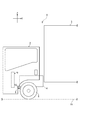
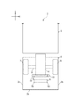
- FIG. 1 is a front view illustrating a vehicle equipped with the blower of the present embodiment.
- FIG. 2 is a view illustrating the vehicle of FIG. 1 in a side view.
- FIG. 3 is a diagram illustrating the vehicle of FIG. 1 in a plan view.
- FIG. 4 is a diagram illustrating the wind speed distribution.
- FIG. 5 is a diagram illustrating a second wind speed distribution.
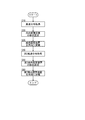
- FIG. 6 is a diagram illustrating a method of adjusting the wind direction of the blower of the present embodiment in the form of a process flow.
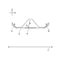
- FIG. 7 is a diagram illustrating changes in the flow of air blown by the wind direction adjusting device and the second wind direction adjusting device.
- the width direction of the vehicle is the X direction
- the vehicle length direction is the Y direction
- the vehicle height direction is the Z direction.
- the wind direction adjusting device 9 and the second wind direction adjusting device 10 described later are shown by solid lines in order to clarify their shapes.
- the vehicle 1 of the present embodiment includes a cab 2 and a loading platform 3 on its body frame.
- the cab 2 is arranged in front of the vehicle 1 (position on the vehicle body frame in front of the loading platform 3), and the driver's seat, the engine 4 (heat source), and the blower 5 are mounted inside the cab 2.
- the loading platform 3 is arranged behind the vehicle 1 (position on the vehicle body frame behind the cab 2), and the load is loaded inside the loading platform 3.
- the engine 4 is a substantially rectangular parallelepiped device that obtains power for vehicle running by mixing and compressing fresh air and fuel inside.
- the engine 4 is arranged at a substantially central position in the vehicle width direction of the vehicle 1 at a position behind the blower 5 and facing the blower 5. Further, the engine 4 is arranged above the front wheel axle 8 connecting the left front wheel 6 and the right front wheel 7 of the vehicle 1 and facing the left front wheel 6 and the right front wheel 7 in the vehicle width direction of the vehicle 1.
- the blower 5 is a device that cools the engine 4 by blowing air to the engine 4.
- the blower 5 is fitted with a fan formed by connecting a plurality of (four in FIG. 1) rotary blades 5c to a rotary shaft 5b extending in the vehicle length direction in a hollow portion of a hollow substantially rectangular parallelepiped housing 5a. It is a configuration to be dressed.
- the plurality of rotary blades 5c rotate around the rotation shaft 5b, so that the blower 5 blows air to the engine 4.
- the blower 5 is arranged inside the cab 2 at a substantially central position in the vehicle width direction of the vehicle 1 at a position in front of the engine 4, the left front wheel 6, the right front wheel 7, and the front wheel axle 8.
- the blower 5 is arranged at a position above the front wheel axle 8.
- the width of the blower 5 is larger than the width of the engine 4, and the height of the blower 5 is larger than the height of the engine 4.
- the engine 4 and the blower 5 are arranged so that the entire front end portion of the engine 4 fits in the hollow portion of the housing 5a of the blower 5 when viewed from the front of the vehicle 1.
- the wind direction adjusting method of the blower of the present embodiment is step S10 (first step), step S20 (second step), step S30 (third step), step S40 (fourth step). , Step S50 (fifth step), and step S60 (sixth step).
- This method is a method that starts from step S10, is carried out in the order of step S10, step S20, step S30, step S40, step S50, and step S60, and ends in step S60.
- the method for adjusting the wind direction of the blower may include at least steps S10, S20, and S30.
- step S10 the wind speed distribution of the blower W by the blower 5 is acquired.
- This wind speed distribution is obtained by, for example, the following method.
- a plurality of propeller anemometers in an area below the engine 4 and the blower 5 and surrounded by the front wheel axle 8, the front end 2a of the cab 2, the left end 2b, and the right end 2c in a plan view of the vehicle 1. Are arranged so that the rotation axes of these propellers extend in the vertical direction.
- each wheel of the vehicle 1 is grounded at a position above the ground 11, it is preferable to arrange a plurality of propeller anemometers below the blower 5 at the same height as the ground contact surface of each wheel.
- a plurality of propeller anemometers are arranged to acquire the wind speed distribution of the blower W by the blower 5.
- the plurality of propeller anemometers are not arranged on the ground 11, the possibility that the detection of the wind speed by the propeller anemometer will be hindered is greatly reduced.
- a method of grounding each wheel of the vehicle 1 at a position above the ground 11 for example, there is a method of grounding only each wheel of the vehicle 1 on the upper surface of a table placed on the ground 11.
- a method may be used in which the entire vehicle 1 is placed on the upper surface excluding the concave portion with respect to the table having the concave portion formed on the upper surface thereof.
- a plurality of propeller anemometers are arranged in this recess at the same height as the contact patch of each wheel.
- the blower 5 is rotationally driven, and the wind speed data of the blower W by the blower 5 is acquired by these a plurality of propeller anemometers.
- the acquired data includes both the horizontal velocity component of the blower W by the blower 5 and the lower velocity component in the vertical direction. However, since the velocity component in the horizontal direction and the velocity component on the lower side in the vertical direction have a positive correlation, the entire acquired data is regarded as the velocity component on the lower side in the vertical direction of the blower W by the blower 5.
- the wind speed distribution of the blower W by the blower 5 is acquired based on the wind speed data acquired by the plurality of propeller anemometers.
- step S20 the shape of the wind direction adjusting device 9 is set based on the wind speed distribution acquired in step S10.
- the wind direction adjusting device 9 is a device that adjusts the direction of the blower W having a velocity component on the lower side in the vertical direction of the set speed threshold value V1 or more with respect to the blower W by the blower 5 upward in the vertical direction. If the set speed threshold value V1 is equal to or higher than this threshold value, the blower W by the blower 5 may be blown onto the ground 11 to generate dust when the vehicle 1 is traveling at a low speed (for example, when traveling at 30 km / h or less). It is a value set in advance by an experiment or the like.
- the shape of the wind direction adjusting device 9 is a plate-like body, and as illustrated in FIG. 4, the upper surface thereof has a velocity component on the lower side in the vertical direction of the set velocity threshold value V1 or more, and is a region A1 or more of the wind velocity distribution. Is set to have an area of.
- the upper surface has a side having a length larger than the width of the hollow portion of the housing 5a of the blower 5.
- step S30 the wind direction adjusting device 9 having the shape set in step S20 is mounted on the vehicle 1, and a part of the direction of the blown W by the blower 5 is adjusted vertically upward by the wind direction adjusting device 9.
- the plate-shaped wind direction adjusting device 9 is extended in the horizontal direction, and the upper surface of the wind direction adjusting device 9 is located below the blower 5 and the engine 4 at a position where the upper surface of the vehicle 1 includes the wind speed distribution region A1 in a plan view. It is arranged above the front wheel axle 8.
- a side having a length larger than the width of the hollow portion of the housing 5a of the blower 5 extends in the vehicle width direction of the vehicle 1.
- the line representing the central position of the blower 5 in the vehicle width direction and the line representing the center position of the wind direction adjusting device 9 in the vehicle width direction in the front view of the vehicle 1 are the same line.
- the front end of the wind direction adjusting device 9 is arranged between the blower 5 and the engine 4 in the direction of the length of the vehicle 1, and the rear end thereof is arranged behind the front end of the engine 4.
- the wind direction adjusting device 9 By arranging the wind direction adjusting device 9 at a position as in the present embodiment, a part of the blown W by the blower 5 collides with the upper surface of the wind direction adjusting device 9, and the wind direction is adjusted upward in the vertical direction. In other words, at least a part of the blower W can be adjusted so as not to face the ground. Since the blower W having a velocity component on the lower side in the vertical direction of the set speed threshold value V1 or higher is adjusted upward in the vertical direction, the blowing of the blower W by the blower 5 to the ground 11 is significantly suppressed.
- the wind direction adjusting device 9 set on the plate-shaped body is mounted on the vehicle 1, the working time of the operator required for creating the wind direction adjusting device 9 for the plate-shaped body and mounting the wind direction adjusting device 9 on the vehicle 1 is greatly increased. Can be shortened to.
- the wind direction adjusting device 9 is set to have an area of the wind speed distribution region A1 or more having a velocity component on the lower side in the vertical direction of the set speed threshold value V1 or more.
- the region A1 does not always have a relatively simple shape such as a rectangle or a circle, it is difficult to set the upper surface of the wind direction adjusting device 9 to have the same shape as the shape of the region A1. Therefore, the upper surface of the wind direction adjusting device 9 is set to have a shape including the region A1.
- the shape of the wind direction adjusting device 9 is set in this way, when the blower W by the blower 5 collides with the upper surface of the wind direction adjusting device 9 excluding the region A1, the collided blower W always flows upward in the vertical direction. Instead, it may flow toward the ground 11 after flowing along the upper surface.
- step S40 the second wind speed distribution, which is the wind speed distribution of the blown W by the blower 5, is acquired with the wind direction adjusting device 9 mounted on the vehicle 1.
- This second wind speed distribution is obtained by, for example, the following method.
- a plurality of propeller anemometers are arranged at each of the front end portion 2a, the left end portion 2b, and the right end portion 2c of the cab 2 so that the rotation axes of these propellers extend in the horizontal direction.
- the air blow W that collides with the upper surface of the wind direction adjusting device 9 except for the region A1 has a larger velocity component in the horizontal direction than the velocity component on the lower side in the vertical direction. Therefore, the propeller anemometer is arranged so that the horizontal velocity component can be obtained relatively easily.
- the blower 5 is rotationally driven, and the wind speed data of the blower W by the blower 5 is acquired by these a plurality of propeller anemometers.
- the acquired data includes both the horizontal velocity component of the blower W by the blower 5 and the lower velocity component in the vertical direction. However, since the velocity component in the horizontal direction and the velocity component on the lower side in the vertical direction have a positive correlation, the entire acquired data is regarded as the data on the velocity component on the lower side in the vertical direction of the blower W by the blower 5. ..
- the second wind speed distribution of the blower W by the blower 5 is acquired based on the wind speed data acquired by the plurality of propeller anemometers.
- step S50 the shape of the second wind direction adjusting device 10 which is a device separate from the wind direction adjusting device 9 is set based on the second wind speed distribution acquired in step S40.
- the second wind direction adjusting device 10 is a device that adjusts the direction of the blower W having a velocity component on the lower side in the vertical direction of the second set speed threshold value V2 or more with respect to the blower W by the blower 5 upward in the vertical direction.
- the second set speed threshold value V2 is a value smaller than the set speed threshold value V1, and if it is equal to or higher than the second set speed threshold value V2, the blower 5 is used when the vehicle 1 is running at a low speed with the wind direction adjusting device 9 mounted on the vehicle 1. It is a value preset by an experiment or the like as there is a possibility that the blast W is blown onto the ground 11 to generate dust.
- the shape of the second wind direction adjusting device 10 is two plate-like bodies having the same shape, and as illustrated in FIG. 5, when the second wind direction adjusting device 10 is mounted on the vehicle 1.
- the area of the projection surface 10a of the second wind direction adjusting device 10 in the side view of the vehicle 1 has an area of the second wind speed distribution region A2 or more having a velocity component on the lower side in the vertical direction of the second set speed threshold V2 or more. Is set to.
- step S60 the second wind direction adjusting device 10 having the shape set in step S50 is mounted on the vehicle 1, and a part of the direction of the blown W by the blower 5 is adjusted vertically upward by the second wind direction adjusting device 10.
- the second wind direction adjusting device 10 of the two plate-shaped bodies is inclined upward in the vertical direction from the inside of the vehicle 1 to the outside, and the projection surface of the second wind direction adjusting device 10 in the side view of the vehicle 1.
- One sheet is connected to both ends of the plate-shaped wind direction adjusting device 9 in the vehicle width direction in a plan view of the vehicle 1 so that 10a is a position including the region A2 of the second wind speed distribution.
- the blower W flowing toward the ground 11 due to the collision with the upper surface of the wind direction adjusting device 9 is vertical by the second wind direction adjusting device 10. Adjusted upwards (adjusted not facing the ground). Therefore, it is possible to further suppress the generation of dust caused by the blown W by the blower 5.
- the second wind direction adjusting device 10 set in the plate-like body as in the wind direction adjusting device 9 is mounted on the vehicle 1, the second wind direction adjusting device 10 in the plate-shaped body can be created and the vehicle of the second wind direction adjusting device 10 can be created. It is possible to significantly reduce the working time of the operator required for mounting on 1.
- the second wind direction adjusting device 10 of the plate-shaped body may be radially extended upward from each side of the upper surface of the wind direction adjusting device 9 of the plate-shaped body, it may collide with the upper surface of the wind direction adjusting device 9.
- the plate-shaped second wind direction adjusting device 10 is connected and arranged at both ends of the plate-shaped wind direction adjusting device 9 in the vehicle width direction in the plan view of the vehicle 1. Is preferable.
- the blower 5 blows air from the gap between the cab 2 and the left front wheel 6 or the right front wheel 7 when viewed from the side of the vehicle 1. It is possible to suppress the atrium of W.
- the wind direction adjusting device 9 and the second wind direction adjusting device 10 are mounted on the vehicle 1 as illustrated in FIG. At the same time, at least a part of the blown W by the blower 5 that blows air to the engine 4 can be adjusted so as not to face the ground.
- the present invention has the effect that at least a part of the air blown by the blower that is mounted on the vehicle and blows to the heat source can be adjusted in a direction that does not face the ground, and the wind direction adjusting method of the blower and the blower are installed. It is useful for vehicles that have been injured.
- Vehicle 2 Cab 2a Front end 2b Left end 2c Right end 3
- Loading platform 4 Engine (heat source) 5 Blower 5a Housing 5b Rotating shaft 5c Rotating blade 6 Left front wheel 7 Right front wheel 8 Front wheel axle 9
- Wind direction adjusting device 10 Second wind direction adjusting device 10a Projection surface 11 Ground A1 Wind speed distribution A2 Second wind speed distribution W
Landscapes
- Engineering & Computer Science (AREA)
- Chemical & Material Sciences (AREA)
- Combustion & Propulsion (AREA)
- Mechanical Engineering (AREA)
- General Engineering & Computer Science (AREA)
- Transportation (AREA)
- Cooling, Air Intake And Gas Exhaust, And Fuel Tank Arrangements In Propulsion Units (AREA)
- Structures Of Non-Positive Displacement Pumps (AREA)
- Aerodynamic Tests, Hydrodynamic Tests, Wind Tunnels, And Water Tanks (AREA)
Abstract
車両1に搭載されて、この車両1に搭載される熱源4に対して送風することで熱源4を冷却する送風機5の風向調整方法において、送風機5による送風Wの風速分布を取得し、この取得した風速分布に基づいて送風機5による送風Wに関して予め設定された設定速度閾値V1以上の鉛直方向下側の速度成分を有する送風Wの方向を鉛直方向上向きに調整する風向調整装置9の形状を設定した後、この設定した形状の風向調整装置9を車両1に搭載して、送風機5による送風Wの一部の方向を風向調整装置9により鉛直方向上向きに調整する。
Description
本開示は、送風機の風向調整方法及び送風機を搭載した車両に関する。
車両に関する技術ではないが、飛行しているヘリコプタの下方に多数の風速計が配設された支持装置を配置して、ヘリコプタの吹き下し分布を測定する技術が提案されている(例えば、特許文献1参照)。
ところで、車両にはエンジン(内燃機関)等の熱源に対して送風するファン(送風機)が搭載されることがあり、このファンによる送風により熱源は冷却される。
しかしながら、車両の低速時には送風機による送風の一部が送風機より下方の地面に吹き付けられることで砂埃が発生して、発生した砂埃が車両の運転者や車両周辺の歩行者等に直撃して迷惑をかける虞がある。そのため、送風機による送風の風速分布を把握した上で、送風の風向が地面に向かないようにその風向を調整することが重要となる。
本開示の目的は、車両に搭載されるとともに熱源に対して送風する送風機による送風の少なくとも一部を地面に向かない方向に調整することができる送風機の風向調整方法及び送風機を搭載した車両を提供することにある。
上記の目的を達成するための本発明の態様の送風機の風向調整方法は、車両に搭載されて、前記車両に搭載される熱源に対して送風することで前記熱源を冷却する送風機の風向調整方法において、前記送風機による送風の風速分布を取得する第1ステップと、前記第1ステップで取得した前記風速分布に基づいて、前記送風機による送風に関して予め設定された設定速度閾値以上の鉛直方向下側の速度成分を有する送風の方向を鉛直方向上向きに調整する風向調整装置の形状を設定する第2ステップと、前記第2ステップで設定した形状の前記風向調整装置を前記車両に搭載して、前記送風機による送風の一部の方向を前記風向調整装置により鉛直方向上向きに調整する第3ステップと、を有することを特徴とする方法である。
また、上記の目的を達成するための本発明の態様の送風機を搭載した車両は、車両に搭載される熱源に対して送風することで前記熱源を冷却するよう構成される送風機と、前記送風機より下方に配置される風向調整装置と、を備え、上記の第2ステップで板状体に設定された前記風向調整装置が水平方向に延在した状態で前記送風機より下方に配置されて構成される。
本開示によれば、車両に搭載されるとともに熱源に対して送風する送風機による送風の少なくとも一部を地面に向かない方向に調整することができる。
以下、本開示の実施形態の送風機の風向調整方法及び送風機を搭載した車両について、図面を参照しながら説明する。なお、本実施形態では、車両の幅方向(車幅方向)をX方向、車両の長さ方向(車長方向)をY方向、車両の高さ方向(車高方向、鉛直方向)をZ方向と定義している。また、図1~図3では後述する風向調整装置9及び第2風向調整装置10に関して、これらの形状を明確にするためにこれらの形状を実線で示している。
図1~図3に例示するように、本実施形態の車両1は、その車体フレーム上にキャブ2及び荷台3を備えている。キャブ2は、車両1の前方(荷台3より前方の車体フレーム上の位置)に配置されて、その内部に運転席、エンジン4(熱源)及び送風機5が搭載されている。荷台3は、車両1の後方(キャブ2より後方の車体フレーム上の位置)に配置されて、その内部に積荷が積載されている。
エンジン4は、その内部で新気と燃料を混合圧縮することで車両走行用の動力を得る略直方体形状の装置である。エンジン4は、車両1の車幅方向の略中央位置で、送風機5より後方の位置に送風機5に対向して配置されている。また、エンジン4は、車両1の左前輪6及び右前輪7を接続する前輪用車軸8より上方で、車両1の車幅方向に関して左前輪6及び右前輪7に対向して配置されている。
送風機5は、エンジン4に対して送風することでエンジン4を冷却する装置である。送風機5は、中空の略直方体形状の筐体5aの中空部分に車長方向に延在する回転軸5bに複数(図1では4枚)の回転翼5cが接続されて構成されるファンが嵌装される構成である。複数の回転翼5cが回転軸5bを回転中心として回転することで送風機5からエンジン4に対して送風される。送風機5は、キャブ2の内部で、車両1の車幅方向の略中央位置で、エンジン4、左前輪6、右前輪7及び前輪用車軸8より前方の位置に配置されている。送風機5は、前輪用車軸8より上方の位置に配置されている。送風機5の幅はエンジン4の幅より大きく、送風機5の高さはエンジン4の高さより大きい。車両1の正面視で、エンジン4の前端部の全体が送風機5の筐体5aの中空部分に収まるように、エンジン4及び送風機5は配置される。
図6に例示するように、本実施形態の送風機の風向調整方法は、ステップS10(第1ステップ)、ステップS20(第2ステップ)、ステップS30(第3ステップ)、ステップS40(第4ステップ)、ステップS50(第5ステップ)、ステップS60(第6ステップ)の各工程を表すステップを有することを特徴とする方法である。この方法は、ステップS10から開始されて、ステップS10、ステップS20、ステップS30、ステップS40、ステップS50、ステップS60の順に実施されていき、ステップS60で終了する方法である。なお、送風機の風向調整方法は、少なくともステップS10、ステップS20、ステップS30を有していればよい。
ステップS10では、送風機5による送風Wの風速分布を取得する。この風速分布は、例えば、以下のような方法で取得される。まず、エンジン4及び送風機5より下方で、かつ、車両1の平面視で前輪用車軸8、キャブ2の前端部2a、左側端部2b及び右側端部2cで囲われる領域に複数のプロペラ風速計をこれらのプロペラの回転軸が鉛直方向に延在するように配置する。
送風機5による送風Wが地面11に対してどの程度吹き付けられているかを把握するために、複数のプロペラ風速計を車両1の各車輪の接地面となる地面11に配置することが好ましい。しかしながら、複数のプロペラ風速計を地面11に配置すると、プロペラ風速計による風速の検出に支障がでる虞がある。
そのため、車両1の各車輪を地面11より上方の位置で接地させた後、複数のプロペラ風速計を各車輪の接地面の高さと同じ高さで送風機5の下方に配置するとよい。複数のプロペラ風速計は送風機5による送風Wの風速分布を取得するために配置される。このようにすることで、複数のプロペラ風速計は地面11に配置されていないため、プロペラ風速計による風速の検出に支障がでる虞は大幅に低減される。車両1の各車輪を地面11より上方の位置で接地させる方法としては、例えば、車両1の各車輪のみを地面11に載置した台の上面に接地させる方法がある。あるいは、その上面に凹部が形成された台に関してこの凹部を除く上面に車両1の全体を載置させる方法でもよい。この方法の場合は、この凹部に複数のプロペラ風速計が各車輪の接地面と同じ高さで配置される。
次いで、送風機5を回転駆動して送風機5による送風Wの風速のデータをこれらの複数のプロペラ風速計で取得する。この取得したデータについては、送風機5による送風Wの水平方向の速度成分と鉛直方向下側の速度成分の両方が含まれる。ただし、水平方向の速度成分と鉛直方向下側の速度成分は正の相関関係があるため、この取得したデータの全体を送風機5による送風Wの鉛直方向下側の速度成分であるとみなす。最後に、複数のプロペラ風速計で取得した風速のデータを基に送風機5による送風Wの風速分布を取得する。
ステップS20では、ステップS10で取得した風速分布に基づいて、風向調整装置9の形状を設定する。風向調整装置9は、送風機5による送風Wに関して設定速度閾値V1以上の鉛直方向下側の速度成分を有する送風Wの方向を鉛直方向上向きに調整する装置である。設定速度閾値V1は、この閾値以上であると車両1の低速走行時(例えば30km/h以下での走行時)に送風機5による送風Wが地面11に吹き付けられて砂埃が発生する虞のあるとして実験等により予め設定される値である。
本実施形態では、風向調整装置9の形状は、板状体で、図4に例示するように、その上面が設定速度閾値V1以上の鉛直方向下側の速度成分を有する風速分布の領域A1以上の面積を有するように設定される。この上面は、送風機5の筐体5aの中空部分の幅より大きい長さの辺を有する。
ステップS30では、ステップS20で設定した形状の風向調整装置9を車両1に搭載して、送風機5による送風Wの一部の方向を風向調整装置9により鉛直方向上向きに調整する。板状体の風向調整装置9は、水平方向に延在させた状態で、車両1の平面視でその上面が風速分布の領域A1を含む位置で、送風機5及びエンジン4より下方に、かつ、前輪用車軸8より上方に配置される。風向調整装置9に関して、送風機5の筐体5aの中空部分の幅より大きい長さの辺は車両1の車幅方向に延在する。車両1の正面視で送風機5の車幅方向の中央位置を表す線と風向調整装置9の車幅方向の中央位置を表す線は同じ線となる。風向調整装置9は、車両1の車長方向に関して、その前端が送風機5とエンジン4の間に配置されて、その後端がエンジン4の前端より後方に配置されている。
本実施形態のような位置に風向調整装置9を配置することで、送風機5による送風Wの一部は風向調整装置9の上面に衝突して、その風向が鉛直方向上向きに調整される。言い換えれば、送風Wの少なくとも一部を地面に向かない方向に調整することができる。設定速度閾値V1以上の鉛直方向下側の速度成分を有する送風Wが鉛直方向上向きに調整されるので、地面11に対する送風機5による送風Wの吹き付けが大幅に抑制される。
また、板状体に設定した風向調整装置9を車両1に搭載するので、板状体の風向調整装置9の作成や風向調整装置9の車両1への搭載に要する作業者の作業時間を大幅に短縮することができる。
上述したように、風向調整装置9は、設定速度閾値V1以上の鉛直方向下側の速度成分を有する風速分布の領域A1以上の面積を有するように設定される。しかしながら、領域A1は長方形や円形等の比較的簡単な形状であるとは限らないため、風向調整装置9の上面を領域A1の形状と同じ形状に設定することは困難である。そのため、風向調整装置9の上面は領域A1を含む形状に設定される。
このように風向調整装置9の形状を設定すると、風向調整装置9の上面に関して領域A1を除く上面に送風機5による送風Wが衝突したときに、この衝突した送風Wは必ずしも鉛直方向上向きには流れず、この上面に沿って流れた後地面11に向かって流れる虞がある。
そこで、ステップS40では、風向調整装置9を車両1に搭載した状態で送風機5による送風Wの風速分布である第2風速分布を取得する。この第2風速分布は、例えば、以下のような方法で取得される。まず、キャブ2の前端部2a、左側端部2b及び右側端部2cの各々に複数のプロペラ風速計をこれらのプロペラの回転軸が水平方向に延在するように配置する。風向調整装置9の上面に関して領域A1を除く上面に衝突した送風Wは、鉛直方向下側の速度成分より水平方向の速度成分の方が大きい。そのため、水平方向の速度成分が比較的取得しやすいようにプロペラ風速計を配置する。
次いで、送風機5を回転駆動して、送風機5による送風Wの風速のデータをこれらの複数のプロペラ風速計で取得する。この取得したデータについては、送風機5による送風Wの水平方向の速度成分と鉛直方向下側の速度成分の両方が含まれる。ただし、水平方向の速度成分と鉛直方向下側の速度成分は正の相関関係があるため、この取得したデータの全体を送風機5による送風Wの鉛直方向下側の速度成分のデータであるとみなす。次いで、複数のプロペラ風速計で取得した風速のデータを基に送風機5による送風Wの第2風速分布を取得する。
ステップS50では、ステップS40で取得した第2風速分布に基づいて、風向調整装置9とは別体の装置である第2風向調整装置10の形状を設定する。第2風向調整装置10は、送風機5による送風Wに関して第2設定速度閾値V2以上の鉛直方向下側の速度成分を有する送風Wの方向を鉛直方向上向きに調整する装置である。第2設定速度閾値V2は、設定速度閾値V1より小さい値で、この第2設定速度閾値V2以上であると車両1に風向調整装置9が搭載された状態で車両1の低速走行時に送風機5による送風Wが地面11に吹き付けられて砂埃が発生する虞のあるとして実験等により予め設定される値である。
本実施形態では、第2風向調整装置10の形状は、2枚の同じ形状の板状体で、図5に例示するように、この第2風向調整装置10が車両1に搭載されるときにおける車両1の側面視での第2風向調整装置10の投影面10aの面積が第2設定速度閾値V2以上の鉛直方向下側の速度成分を有する第2風速分布の領域A2以上の面積を有するように設定される。
ステップS60では、ステップS50で設定した形状の第2風向調整装置10を車両1に搭載して、送風機5による送風Wの一部の方向を第2風向調整装置10により鉛直方向上向きに調整する。2枚の板状体の第2風向調整装置10は、車両1の内部から外部に向かう方向に鉛直方向上向きに傾斜した状態で、車両1の側面視での第2風向調整装置10の投影面10aが第2風速分布の領域A2を含む位置となるように、車両1の平面視で板状体の風向調整装置9の車幅方向の両端に1枚ずつ接続されて配置される。
本実施形態のような位置に第2風向調整装置10を配置することで、風向調整装置9の上面への衝突に起因して地面11に向かって流れる送風Wが第2風向調整装置10により鉛直方向上向きに調整される(地面に向かない方向に調整される)。したがって、送風機5による送風Wに起因した砂埃の発生をさらに抑制することができる。
また、風向調整装置9と同様に板状体に設定した第2風向調整装置10を車両1に搭載するので、板状体の第2風向調整装置10の作成や第2風向調整装置10の車両1への搭載に要する作業者の作業時間を大幅に短縮することができる。
なお、板状体の風向調整装置9の上面の各辺から鉛直方向上向きに板状体の第2風向調整装置10を放射状に延在させる構成としてもよいが、風向調整装置9の上面に衝突した後の送風機5による送風Wに関して、車両1の前方または後方に向かう送風Wは地面11に衝突する前にキャブ2の内部に配置された各種装置に衝突することが多い。そのため、本実施形態のように、車両1の平面視で板状体の風向調整装置9の車幅方向の両端に板状体の第2風向調整装置10を1枚ずつ接続させて配置することが好ましい。このようにすることで、第2風向調整装置10の作成に要する作業時間やコストを低減しつつ、車両1の側面視でキャブ2と左前輪6または右前輪7の隙間からの送風機5による送風Wの吹き抜けを抑制することができる。
以上より、本実施形態の送風機の風向調整方法及び送風機5を搭載した車両1によれば、図7に例示するように、風向調整装置9及び第2風向調整装置10により車両1に搭載されるとともにエンジン4に対して送風する送風機5による送風Wの少なくとも一部を地面に向かない方向に調整することができる。
本出願は、2019年3月19日付で出願された日本国特許出願(特願2019-051546)に基づくものであり、その内容はここに参照として取り込まれる。
本発明は、車両に搭載されるとともに熱源に対して送風する送風機による送風の少なくとも一部を地面に向かない方向に調整することができるという効果を有し、送風機の風向調整方法及び送風機を搭載した車両等に有用である。
1 車両
2 キャブ
2a 前端部
2b 左側端部
2c 右側端部
3 荷台
4 エンジン(熱源)
5 送風機
5a 筐体
5b 回転軸
5c 回転翼
6 左前輪
7 右前輪
8 前輪用車軸
9 風向調整装置
10 第2風向調整装置
10a 投影面
11 地面
A1 風速分布
A2 第2風速分布
W 送風
2 キャブ
2a 前端部
2b 左側端部
2c 右側端部
3 荷台
4 エンジン(熱源)
5 送風機
5a 筐体
5b 回転軸
5c 回転翼
6 左前輪
7 右前輪
8 前輪用車軸
9 風向調整装置
10 第2風向調整装置
10a 投影面
11 地面
A1 風速分布
A2 第2風速分布
W 送風
Claims (8)
- 車両に搭載されて、前記車両に搭載される熱源に対して送風することで前記熱源を冷却する送風機の風向調整方法において、
前記送風機による送風の風速分布を取得する第1ステップと、
前記第1ステップで取得した前記風速分布に基づいて、前記送風機による送風に関して予め設定された設定速度閾値以上の鉛直方向下側の速度成分を有する送風の方向を鉛直方向上向きに調整する風向調整装置の形状を設定する第2ステップと、
前記第2ステップで設定した形状の前記風向調整装置を前記車両に搭載して、前記送風機による送風の一部の方向を前記風向調整装置により鉛直方向上向きに調整する第3ステップと、を有することを特徴とする送風機の風向調整方法。 - 前記第1ステップで、前記車両の各車輪を地面より上方の位置で接地させた後、複数のプロペラ風速計を前記各車輪の接地面の高さと同じ高さで前記送風機の下方に配置して、前記複数のプロペラ風速計により前記送風機による前記送風の前記風速分布を取得することを特徴とする請求項1に記載の送風機の風向調整方法。
- 前記風向調整装置を前記車両に搭載した状態で前記送風機による送風の風速分布である第2風速分布を取得する第4ステップと、
前記第4ステップで取得した前記第2風速分布に基づいて、前記送風機による前記送風に関して前記設定速度閾値より小さい値として予め設定された第2設定速度閾値以上の鉛直方向下側の速度成分を有する送風の方向を鉛直方向上向きに調整する第2風向調整装置の形状を設定する第5ステップと、
前記第5ステップで設定した形状の前記第2風向調整装置を前記車両に搭載して、前記送風機による前記送風の一部の方向を前記第2風向調整装置により鉛直方向上向きに調整する第6ステップと、を有することを特徴とする請求項1または2に記載の送風機の風向調整方法。 - 前記第2ステップで前記風向調整装置前記の形状を板状体に設定した後、前記第3ステップで前記風向調整装置を水平方向に延在した状態で前記送風機より下方に配置して前記車両に搭載することを特徴とする請求項1~3のいずれか1項に記載の送風機の風向調整方法。
- 前記第5ステップで前記第2風向調整装置の形状を前記板状体に設定した後、前記第6ステップで前記第2風向調整装置を鉛直方向上向きに傾斜した状態で板前記状体の前記風向調整装置に接続して前記車両に搭載することを特徴とする請求項4に記載の送風機の風向調整方法。
- 車両に搭載される熱源に対して送風することで前記熱源を冷却するよう構成される送風機と、
前記送風機より下方に配置される風向調整装置と、を備え、
請求項1に記載の第2ステップで板状体に設定された前記風向調整装置が水平方向に延在した状態で前記送風機より下方に配置されて構成される、送風機を搭載した車両。 - 前記風向調整装置とは別体の装置である第2風向調整装置をさらに備え、
前記風向調整装置は、前記送風機による前記送風に関して第1設定速度閾値以上の鉛直方向下側の速度成分を有する送風の方向を、鉛直方向上向きの第1方向に調整する装置であり、
前記第2風向調整装置は、前記送風機による前記送風に関して、前記第1設定速度閾値より小さい値である第2設定速度閾値V2以上の鉛直方向下側の速度成分を有する送風の方向を、鉛直方向上向きの第2方向に調整する装置である、
請求項6に記載の送風機を搭載した車両。 - 前記第2風向調整装置は、前記風向調整装置の車幅方向の両端に1枚ずつ接続されて配置されることを特徴とする、請求項7に記載の送風機を搭載した車両。
Priority Applications (2)
| Application Number | Priority Date | Filing Date | Title |
|---|---|---|---|
| CN202080021350.XA CN113613928B (zh) | 2019-03-19 | 2020-03-11 | 送风机的风向调整方法以及搭载送风机的车辆 |
| PH1/2021/552222A PH12021552222A1 (en) | 2019-03-19 | 2020-03-11 | Method for adjusting wind direction of blower, and vehicle equipped with blower |
Applications Claiming Priority (2)
| Application Number | Priority Date | Filing Date | Title |
|---|---|---|---|
| JP2019051546A JP2020152194A (ja) | 2019-03-19 | 2019-03-19 | 送風機の風向調整方法及び送風機を搭載した車両 |
| JP2019-051546 | 2019-03-19 |
Publications (1)
| Publication Number | Publication Date |
|---|---|
| WO2020189429A1 true WO2020189429A1 (ja) | 2020-09-24 |
Family
ID=72519838
Family Applications (1)
| Application Number | Title | Priority Date | Filing Date |
|---|---|---|---|
| PCT/JP2020/010435 Ceased WO2020189429A1 (ja) | 2019-03-19 | 2020-03-11 | 送風機の風向調整方法及び送風機を搭載した車両 |
Country Status (4)
| Country | Link |
|---|---|
| JP (1) | JP2020152194A (ja) |
| CN (1) | CN113613928B (ja) |
| PH (1) | PH12021552222A1 (ja) |
| WO (1) | WO2020189429A1 (ja) |
Citations (3)
| Publication number | Priority date | Publication date | Assignee | Title |
|---|---|---|---|---|
| JP2002356115A (ja) * | 2001-05-31 | 2002-12-10 | Hitachi Constr Mach Co Ltd | 建設機械の冷却装置 |
| JP2015037933A (ja) * | 2013-08-15 | 2015-02-26 | ディーア・アンド・カンパニーDeere And Company | 動的バッフルを備えた複合冷却システム |
| JP2018033431A (ja) * | 2016-09-02 | 2018-03-08 | 株式会社クボタ | 芝刈機 |
Family Cites Families (5)
| Publication number | Priority date | Publication date | Assignee | Title |
|---|---|---|---|---|
| JP5293731B2 (ja) * | 2010-12-21 | 2013-09-18 | 日産自動車株式会社 | 車両用送風装置 |
| JP2014070593A (ja) * | 2012-09-28 | 2014-04-21 | Daihatsu Motor Co Ltd | 内燃機関の冷暖装置 |
| JP6504934B2 (ja) * | 2015-06-23 | 2019-04-24 | シャープ株式会社 | 送風装置 |
| JP2017203565A (ja) * | 2016-05-09 | 2017-11-16 | 三菱電機株式会社 | 送風機 |
| EP3366899B1 (en) * | 2016-12-28 | 2019-11-06 | Komatsu Ltd. | Utility vehicle, and method for adjusting position of movable part of utility vehicle |
-
2019
- 2019-03-19 JP JP2019051546A patent/JP2020152194A/ja active Pending
-
2020
- 2020-03-11 CN CN202080021350.XA patent/CN113613928B/zh active Active
- 2020-03-11 WO PCT/JP2020/010435 patent/WO2020189429A1/ja not_active Ceased
- 2020-03-11 PH PH1/2021/552222A patent/PH12021552222A1/en unknown
Patent Citations (3)
| Publication number | Priority date | Publication date | Assignee | Title |
|---|---|---|---|---|
| JP2002356115A (ja) * | 2001-05-31 | 2002-12-10 | Hitachi Constr Mach Co Ltd | 建設機械の冷却装置 |
| JP2015037933A (ja) * | 2013-08-15 | 2015-02-26 | ディーア・アンド・カンパニーDeere And Company | 動的バッフルを備えた複合冷却システム |
| JP2018033431A (ja) * | 2016-09-02 | 2018-03-08 | 株式会社クボタ | 芝刈機 |
Also Published As
| Publication number | Publication date |
|---|---|
| CN113613928A (zh) | 2021-11-05 |
| CN113613928B (zh) | 2023-12-26 |
| PH12021552222A1 (en) | 2022-05-30 |
| JP2020152194A (ja) | 2020-09-24 |
Similar Documents
| Publication | Publication Date | Title |
|---|---|---|
| US6708920B2 (en) | Air vehicle | |
| CN109070953B (zh) | 主动底部面板组件 | |
| JP6446013B2 (ja) | 整流装置 | |
| CN110893758A (zh) | 车辆 | |
| JP2020152194A (ja) | 送風機の風向調整方法及び送風機を搭載した車両 | |
| JP2003278641A (ja) | 車両用風力発電装置 | |
| JP7155880B2 (ja) | 自動車のデフレクタ構造 | |
| CN103821917B (zh) | 用于冷却机动车辆的车桥差速器的装置和方法 | |
| CN112477792B (zh) | 一种车辆前进气格栅安装结构 | |
| CN109959520A (zh) | 一种测试用目标车辆高速移动底盘 | |
| ES2607117T3 (es) | Sistema de refrigeración activa de vehículo | |
| MY196730A (en) | Structure for mounting air cleaner in vehicle | |
| JP2021023027A (ja) | 車載用風力発電装置 | |
| JP2021098477A (ja) | 車両用気流制御装置 | |
| JP2011057172A (ja) | タイヤ昇温装置 | |
| CN106627412B (zh) | 牌照框支架 | |
| JP2014184928A (ja) | 冷却構造 | |
| CN201472284U (zh) | 防止汽车撞击飞虫的防护系统 | |
| KR102594491B1 (ko) | 모형 자동차용 차대 동력계 | |
| CN206124939U (zh) | 牌照框支架 | |
| CN210157011U (zh) | 一种同轴步进电机 | |
| CN206851248U (zh) | 电动汽车驱动器散热用导风装置 | |
| JP2010188927A (ja) | タイヤ昇温装置 | |
| JP3220598U (ja) | ドアミラーカバー | |
| CN121106513A (zh) | 一种用于车辆的下压力装置及车辆 |
Legal Events
| Date | Code | Title | Description |
|---|---|---|---|
| 121 | Ep: the epo has been informed by wipo that ep was designated in this application |
Ref document number: 20773138 Country of ref document: EP Kind code of ref document: A1 |
|
| NENP | Non-entry into the national phase |
Ref country code: DE |
|
| 122 | Ep: pct application non-entry in european phase |
Ref document number: 20773138 Country of ref document: EP Kind code of ref document: A1 |