WO2020189398A1 - モータ、モータの状態検出装置、及び、モータの状態判定装置 - Google Patents
モータ、モータの状態検出装置、及び、モータの状態判定装置 Download PDFInfo
- Publication number
- WO2020189398A1 WO2020189398A1 PCT/JP2020/010194 JP2020010194W WO2020189398A1 WO 2020189398 A1 WO2020189398 A1 WO 2020189398A1 JP 2020010194 W JP2020010194 W JP 2020010194W WO 2020189398 A1 WO2020189398 A1 WO 2020189398A1
- Authority
- WO
- WIPO (PCT)
- Prior art keywords
- bearing
- motor
- rotor
- outer ring
- inner ring
- Prior art date
- Legal status (The legal status is an assumption and is not a legal conclusion. Google has not performed a legal analysis and makes no representation as to the accuracy of the status listed.)
- Ceased
Links
Images







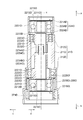


Classifications
-
- F—MECHANICAL ENGINEERING; LIGHTING; HEATING; WEAPONS; BLASTING
- F16—ENGINEERING ELEMENTS AND UNITS; GENERAL MEASURES FOR PRODUCING AND MAINTAINING EFFECTIVE FUNCTIONING OF MACHINES OR INSTALLATIONS; THERMAL INSULATION IN GENERAL
- F16C—SHAFTS; FLEXIBLE SHAFTS; ELEMENTS OR CRANKSHAFT MECHANISMS; ROTARY BODIES OTHER THAN GEARING ELEMENTS; BEARINGS
- F16C19/00—Bearings with rolling contact, for exclusively rotary movement
- F16C19/54—Systems consisting of a plurality of bearings with rolling friction
- F16C19/55—Systems consisting of a plurality of bearings with rolling friction with intermediate floating or independently-driven rings rotating at reduced speed or with other differential ball or roller bearings
-
- H—ELECTRICITY
- H02—GENERATION; CONVERSION OR DISTRIBUTION OF ELECTRIC POWER
- H02K—DYNAMO-ELECTRIC MACHINES
- H02K5/00—Casings; Enclosures; Supports
- H02K5/04—Casings or enclosures characterised by the shape, form or construction thereof
- H02K5/16—Means for supporting bearings, e.g. insulating supports or means for fitting bearings in the bearing-shields
- H02K5/173—Means for supporting bearings, e.g. insulating supports or means for fitting bearings in the bearing-shields using bearings with rolling contact, e.g. ball bearings
-
- F—MECHANICAL ENGINEERING; LIGHTING; HEATING; WEAPONS; BLASTING
- F16—ENGINEERING ELEMENTS AND UNITS; GENERAL MEASURES FOR PRODUCING AND MAINTAINING EFFECTIVE FUNCTIONING OF MACHINES OR INSTALLATIONS; THERMAL INSULATION IN GENERAL
- F16C—SHAFTS; FLEXIBLE SHAFTS; ELEMENTS OR CRANKSHAFT MECHANISMS; ROTARY BODIES OTHER THAN GEARING ELEMENTS; BEARINGS
- F16C19/00—Bearings with rolling contact, for exclusively rotary movement
- F16C19/52—Bearings with rolling contact, for exclusively rotary movement with devices affected by abnormal or undesired conditions
-
- F—MECHANICAL ENGINEERING; LIGHTING; HEATING; WEAPONS; BLASTING
- F16—ENGINEERING ELEMENTS AND UNITS; GENERAL MEASURES FOR PRODUCING AND MAINTAINING EFFECTIVE FUNCTIONING OF MACHINES OR INSTALLATIONS; THERMAL INSULATION IN GENERAL
- F16C—SHAFTS; FLEXIBLE SHAFTS; ELEMENTS OR CRANKSHAFT MECHANISMS; ROTARY BODIES OTHER THAN GEARING ELEMENTS; BEARINGS
- F16C41/00—Other accessories, e.g. devices integrated in the bearing not relating to the bearing function as such
- F16C41/007—Encoders, e.g. parts with a plurality of alternating magnetic poles
-
- H—ELECTRICITY
- H02—GENERATION; CONVERSION OR DISTRIBUTION OF ELECTRIC POWER
- H02K—DYNAMO-ELECTRIC MACHINES
- H02K11/00—Structural association of dynamo-electric machines with electric components or with devices for shielding, monitoring or protection
- H02K11/20—Structural association of dynamo-electric machines with electric components or with devices for shielding, monitoring or protection for measuring, monitoring, testing, protecting or switching
- H02K11/21—Devices for sensing speed or position, or actuated thereby
- H02K11/215—Magnetic effect devices, e.g. Hall-effect or magneto-resistive elements
-
- H—ELECTRICITY
- H02—GENERATION; CONVERSION OR DISTRIBUTION OF ELECTRIC POWER
- H02K—DYNAMO-ELECTRIC MACHINES
- H02K11/00—Structural association of dynamo-electric machines with electric components or with devices for shielding, monitoring or protection
- H02K11/20—Structural association of dynamo-electric machines with electric components or with devices for shielding, monitoring or protection for measuring, monitoring, testing, protecting or switching
- H02K11/27—Devices for sensing current, or actuated thereby
-
- H—ELECTRICITY
- H02—GENERATION; CONVERSION OR DISTRIBUTION OF ELECTRIC POWER
- H02K—DYNAMO-ELECTRIC MACHINES
- H02K11/00—Structural association of dynamo-electric machines with electric components or with devices for shielding, monitoring or protection
- H02K11/30—Structural association with control circuits or drive circuits
-
- H—ELECTRICITY
- H02—GENERATION; CONVERSION OR DISTRIBUTION OF ELECTRIC POWER
- H02K—DYNAMO-ELECTRIC MACHINES
- H02K5/00—Casings; Enclosures; Supports
- H02K5/04—Casings or enclosures characterised by the shape, form or construction thereof
- H02K5/16—Means for supporting bearings, e.g. insulating supports or means for fitting bearings in the bearing-shields
- H02K5/173—Means for supporting bearings, e.g. insulating supports or means for fitting bearings in the bearing-shields using bearings with rolling contact, e.g. ball bearings
- H02K5/1735—Means for supporting bearings, e.g. insulating supports or means for fitting bearings in the bearing-shields using bearings with rolling contact, e.g. ball bearings radially supporting the rotary shaft at only one end of the rotor
-
- H—ELECTRICITY
- H02—GENERATION; CONVERSION OR DISTRIBUTION OF ELECTRIC POWER
- H02K—DYNAMO-ELECTRIC MACHINES
- H02K7/00—Arrangements for handling mechanical energy structurally associated with dynamo-electric machines, e.g. structural association with mechanical driving motors or auxiliary dynamo-electric machines
- H02K7/08—Structural association with bearings
- H02K7/083—Structural association with bearings radially supporting the rotary shaft at both ends of the rotor
-
- H—ELECTRICITY
- H02—GENERATION; CONVERSION OR DISTRIBUTION OF ELECTRIC POWER
- H02K—DYNAMO-ELECTRIC MACHINES
- H02K7/00—Arrangements for handling mechanical energy structurally associated with dynamo-electric machines, e.g. structural association with mechanical driving motors or auxiliary dynamo-electric machines
- H02K7/08—Structural association with bearings
- H02K7/085—Structural association with bearings radially supporting the rotary shaft at only one end of the rotor
-
- H—ELECTRICITY
- H02—GENERATION; CONVERSION OR DISTRIBUTION OF ELECTRIC POWER
- H02K—DYNAMO-ELECTRIC MACHINES
- H02K7/00—Arrangements for handling mechanical energy structurally associated with dynamo-electric machines, e.g. structural association with mechanical driving motors or auxiliary dynamo-electric machines
- H02K7/14—Structural association with mechanical loads, e.g. with hand-held machine tools or fans
-
- F—MECHANICAL ENGINEERING; LIGHTING; HEATING; WEAPONS; BLASTING
- F16—ENGINEERING ELEMENTS AND UNITS; GENERAL MEASURES FOR PRODUCING AND MAINTAINING EFFECTIVE FUNCTIONING OF MACHINES OR INSTALLATIONS; THERMAL INSULATION IN GENERAL
- F16C—SHAFTS; FLEXIBLE SHAFTS; ELEMENTS OR CRANKSHAFT MECHANISMS; ROTARY BODIES OTHER THAN GEARING ELEMENTS; BEARINGS
- F16C19/00—Bearings with rolling contact, for exclusively rotary movement
- F16C19/02—Bearings with rolling contact, for exclusively rotary movement with bearing balls essentially of the same size in one or more circular rows
- F16C19/04—Bearings with rolling contact, for exclusively rotary movement with bearing balls essentially of the same size in one or more circular rows for radial load mainly
- F16C19/06—Bearings with rolling contact, for exclusively rotary movement with bearing balls essentially of the same size in one or more circular rows for radial load mainly with a single row or balls
-
- F—MECHANICAL ENGINEERING; LIGHTING; HEATING; WEAPONS; BLASTING
- F16—ENGINEERING ELEMENTS AND UNITS; GENERAL MEASURES FOR PRODUCING AND MAINTAINING EFFECTIVE FUNCTIONING OF MACHINES OR INSTALLATIONS; THERMAL INSULATION IN GENERAL
- F16C—SHAFTS; FLEXIBLE SHAFTS; ELEMENTS OR CRANKSHAFT MECHANISMS; ROTARY BODIES OTHER THAN GEARING ELEMENTS; BEARINGS
- F16C2233/00—Monitoring condition, e.g. temperature, load, vibration
-
- F—MECHANICAL ENGINEERING; LIGHTING; HEATING; WEAPONS; BLASTING
- F16—ENGINEERING ELEMENTS AND UNITS; GENERAL MEASURES FOR PRODUCING AND MAINTAINING EFFECTIVE FUNCTIONING OF MACHINES OR INSTALLATIONS; THERMAL INSULATION IN GENERAL
- F16C—SHAFTS; FLEXIBLE SHAFTS; ELEMENTS OR CRANKSHAFT MECHANISMS; ROTARY BODIES OTHER THAN GEARING ELEMENTS; BEARINGS
- F16C2360/00—Engines or pumps
- F16C2360/46—Fans, e.g. ventilators
-
- F—MECHANICAL ENGINEERING; LIGHTING; HEATING; WEAPONS; BLASTING
- F16—ENGINEERING ELEMENTS AND UNITS; GENERAL MEASURES FOR PRODUCING AND MAINTAINING EFFECTIVE FUNCTIONING OF MACHINES OR INSTALLATIONS; THERMAL INSULATION IN GENERAL
- F16C—SHAFTS; FLEXIBLE SHAFTS; ELEMENTS OR CRANKSHAFT MECHANISMS; ROTARY BODIES OTHER THAN GEARING ELEMENTS; BEARINGS
- F16C2380/00—Electrical apparatus
- F16C2380/26—Dynamo-electric machines or combinations therewith, e.g. electro-motors and generators
-
- F—MECHANICAL ENGINEERING; LIGHTING; HEATING; WEAPONS; BLASTING
- F16—ENGINEERING ELEMENTS AND UNITS; GENERAL MEASURES FOR PRODUCING AND MAINTAINING EFFECTIVE FUNCTIONING OF MACHINES OR INSTALLATIONS; THERMAL INSULATION IN GENERAL
- F16C—SHAFTS; FLEXIBLE SHAFTS; ELEMENTS OR CRANKSHAFT MECHANISMS; ROTARY BODIES OTHER THAN GEARING ELEMENTS; BEARINGS
- F16C41/00—Other accessories, e.g. devices integrated in the bearing not relating to the bearing function as such
-
- H—ELECTRICITY
- H02—GENERATION; CONVERSION OR DISTRIBUTION OF ELECTRIC POWER
- H02K—DYNAMO-ELECTRIC MACHINES
- H02K21/00—Synchronous motors having permanent magnets; Synchronous generators having permanent magnets
- H02K21/12—Synchronous motors having permanent magnets; Synchronous generators having permanent magnets with stationary armatures and rotating magnets
- H02K21/22—Synchronous motors having permanent magnets; Synchronous generators having permanent magnets with stationary armatures and rotating magnets with magnets rotating around the armatures, e.g. flywheel magnetos
-
- H—ELECTRICITY
- H02—GENERATION; CONVERSION OR DISTRIBUTION OF ELECTRIC POWER
- H02K—DYNAMO-ELECTRIC MACHINES
- H02K2213/00—Specific aspects, not otherwise provided for and not covered by codes H02K2201/00 - H02K2211/00
- H02K2213/06—Machines characterised by the presence of fail safe, back up, redundant or other similar emergency arrangements
Definitions
- the present invention relates to a motor, a motor state detection device, and a motor state determination device.
- One of the causes of the failure of the motor is an abnormality such as a failure of the bearing that supports the rotating shaft attached to the rotor.
- the first temperature sensor that detects the temperature of the first bearing installed on one end side of the shaft member of the electric motor (motor), the shaft member, and others.
- a second temperature sensor that detects the temperature of the second bearing installed on the end side, and the presence or absence of a failure sign of the first bearing and the second bearing based on the difference between the temperature of the first bearing and the temperature of the second bearing.
- a bearing failure sign diagnostic means for diagnosing is known (see Patent Document 1).
- a motor for a cooling fan for cooling the inside of a server (hereinafter referred to as a "fan motor”) is required to have high reliability because a failure of the fan motor interferes with the use of the server. ..
- the high reliability of a bearing in a fan motor specifically means that the period until an abnormality occurs in the bearing, that is, the life of the bearing is long, or the life of the bearing can be predicted.
- Patent Document 1 Although the technology of Patent Document 1 can predict the life of the bearing, it has not been considered to extend the life of the bearing. Further, in the technique of Patent Document 1, since it is necessary to provide a temperature sensor for each of the two bearings, it is necessary to secure a mounting place for the temperature sensor, and the configuration of the motor is complicated.
- the present invention is an example of the above-mentioned problems, and an object of the present invention is to provide a technique capable of improving the reliability of bearings in a motor.
- the motor according to the present invention includes a rotor having a rotating shaft, a stator arranged so as to face each other in the circumferential direction of the rotor, and a pair of bearings that rotatably support the rotating shaft.
- the pair of bearing portions each include a first bearing that can rotate with the rotating shaft and a second bearing that can rotate with the first bearing, and the first bearing is normal. When the first bearing rotates with the rotating shaft, and when the first bearing becomes abnormal, the second bearing also rotates with the rotating shaft with the first bearing.
- the first bearing includes a first inner ring that can rotate together with the rotating shaft, a first outer ring provided on the outer peripheral side of the first inner ring, and the first inner ring. It has a first rolling element arranged between the first outer ring, and the second bearing is provided on the outer peripheral side of the second inner ring and the second inner ring that can rotate with the first outer ring. It has a second outer ring and a second rolling element arranged between the second inner ring and the second outer ring.
- the second bearing is provided at a position separated from the first bearing in the axial direction of the rotating shaft.
- the second bearing is provided on the outer peripheral side of the first bearing.
- the pair of bearing portions each include a coupling portion that rotatably connects the first outer ring and the second inner ring.
- the first bearing has a kinematic viscosity lower than the kinematic viscosity of the second bearing.
- the motor according to one aspect of the present invention further includes a bearing motion detecting section for detecting the motion of the bearing section
- the first bearing has a first inner ring that can rotate with the rotating shaft and an outer circumference of the first inner ring. It has a first outer ring provided on the side and a first rolling element arranged between the first inner ring and the first outer ring, and the second bearing can rotate together with the first outer ring. It has a second inner ring, a second outer ring provided on the outer peripheral side of the second inner ring, and a second rolling element arranged between the second inner ring and the second outer ring.
- the bearing motion detection unit outputs bearing motion information according to the rotational motion of the first outer ring.
- the bearing motion detection unit is a bearing motion detection magnet that can rotate together with the first outer ring, and a bearing that outputs the bearing motion information according to the rotation motion of the bearing motion detection magnet. It has a motion detection sensor.
- the motor according to one aspect of the present invention includes a first substrate provided on the outer peripheral side of the bearing portion, and the bearing motion detection sensor is mounted on the first substrate.
- the second bearing is provided at a position separated from the first bearing in the axial direction of the rotating shaft, and the pair of bearing portions is provided with the first outer ring.
- Each includes a coupling portion that rotatably connects the second inner ring.
- the bearing motion detection unit is provided on the outer peripheral side of the coupling unit.
- the second substrate arranged with the stator sandwiched between the first substrate and the second substrate mounted on the second substrate in the axial direction of the rotation axis. It is provided with a rotor operation detection unit that outputs rotor operation information according to the rotation operation of the rotor.
- the pair of bearing portions each have a coupling portion in which the first bearing and the second bearing are coupled so as to rotate in conjunction with each other.
- the coupling portions of the pair of bearing portions are coupled so as to rotate in conjunction with each other.
- the first bearing includes a first inner ring that can rotate together with the rotating shaft, a first outer ring provided on the outer peripheral side of the first inner ring, and the first inner ring. It has a first rolling element arranged between the first outer ring and the second bearing, and the second bearing is provided at a position separated from the first bearing in the axial direction of the rotating shaft.
- a second inner ring that can rotate together with the first outer ring, a second outer ring provided on the outer peripheral side of the second inner ring, and a second rolling element arranged between the second inner ring and the second outer ring.
- the coupling portion rotatably connects the first outer ring and the second inner ring.
- the motor according to one aspect of the present invention includes a bearing motion detecting section that detects the motion of at least one of the pair of bearing sections, and the bearing motion detecting section is a bearing motion corresponding to the rotational motion of the first outer ring. Output information.
- the bearing motion detection unit is a bearing motion detection magnet that can rotate together with the first outer ring, and a bearing that outputs the bearing motion information according to the rotation motion of the bearing motion detection magnet. It has a motion detection sensor.
- the bearing motion detection sensor is mounted on a substrate provided on the outer peripheral side of the bearing portion provided with the bearing motion detection portion among the pair of bearing portions.
- the bearing motion detection unit is provided on the outer peripheral side of the coupling unit.
- a rotor operation detection unit that outputs rotor operation information according to the rotation operation of the rotor is mounted on the substrate.
- the motor state detection device is a device that detects the state of the bearing portion of the motor, and the motor is a rotor having a rotation shaft and a circumferential direction of the rotor.
- a stator arranged so as to face each other, a first bearing that rotatably supports the rotating shaft and is rotatable together with the rotating shaft, a second bearing that is rotatable together with the first bearing, and the first bearing.
- a pair of bearing portions each having a coupling portion coupled so as to rotate in conjunction with the second bearing and at least one of the pair of bearing portions are provided to rotate the first bearing.
- An information acquisition unit that includes a bearing operation detection unit that outputs corresponding bearing operation information and acquires rotation information that is information based on the rotational movement of the motor, and an information acquisition unit that acquires rotation information based on the rotation information acquired by the information acquisition unit.
- a state detection unit for detecting the state of rotational movement of the bearing unit is provided.
- the rotation information is information regarding the rotation speed of the rotor.
- the rotation information is information regarding the motor current of the motor.
- the motor state detecting device it is determined which of the first bearing and the second bearing is rotating together with the rotating shaft in the bearing portion based on the rotation information.
- the motor state determination device is a state determination device that determines the state of the bearing portion of the motor, and the motor is a first inner ring that can rotate together with the rotation shaft of the rotor. It has a first outer ring provided on the outer peripheral side of the first inner ring and a first rolling element arranged between the first inner ring and the first outer ring, and rotatably supports the rotation shaft. Between the first bearing, the second inner ring that can rotate with the first outer ring, the second outer ring provided on the outer peripheral side of the second inner ring, and the second inner ring and the second outer ring.
- the state determination device includes a second bearing having a second rolling element arranged in the above, and a bearing operation detection unit that outputs bearing operation information according to the rotational operation of the first outer ring.
- a state determination unit for determining the state of rotational motion of the first bearing based on the bearing operation information output by the detection unit is provided.
- the state determination unit determines whether or not the first bearing has deteriorated based on the bearing operation information.
- the motor includes a rotor operation detection unit that outputs rotor operation information according to the rotation operation of the rotor, and the state determination unit includes the bearing operation information and the bearing operation information.
- the state of the rotational movement of the first bearing is determined based on the rotor operation information.
- the bearing operation information is information according to the rotation speed of the first outer ring
- the rotor operation information is information according to the rotation speed of the rotor. is there.
- the state determination unit is based on the information according to the rotation speed of the first outer ring and the information according to the rotation speed of the rotor. Determine if the bearing is defective.
- the motor state determination device includes a pair of bearing portions each having a coupling portion in which the first bearing and the second bearing are coupled so as to rotate in conjunction with each other.
- the coupling portion rotatably couples the first outer ring and the second inner ring
- the bearing motion detection portion is provided on at least one of the pair of bearing portions
- the state determination device determines the state.
- the unit determines the state of rotational motion of the pair of bearing units based on the bearing operation information output by the bearing operation detection unit.
- the state determination device determines whether or not at least one of the pair of bearing portions is deteriorated based on the bearing operation information.
- the bearing motion detection unit is provided on one of the pair of bearing portions, and when one of the pair of bearing portions deteriorates, the coupling portion. It is determined that the first bearing possessed by one of the pair of bearing portions has deteriorated due to the rotational operation of.
- the motor includes a rotor operation detection unit that outputs rotor operation information according to the rotation operation of the rotor, and the state determination unit includes the bearing operation information and the bearing operation information.
- the state of the rotational motion of the first bearing is determined based on the rotor operation information.
- the bearing operation information is information according to the rotation speed of the first outer ring
- the rotor operation information is information according to the rotation speed of the rotor. is there.
- the reliability of bearings in a motor can be improved.
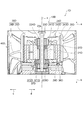
- FIG. 5 is a cross-sectional view schematically showing the configuration of the fan device shown in FIG.
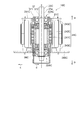
- FIG. 5 is a cross-sectional view schematically showing a configuration of a rotating shaft and a bearing portion included in the fan device shown in FIG. 1.
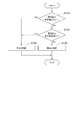
- It is a flowchart for showing the transition of the operation of the bearing part of the motor provided in the fan device shown in FIG.
- It is a schematic diagram which shows the transition between the rotation speed of the motor provided in the fan device shown in FIG. 1 and the motor current.
- It is a functional block diagram of the drive control device of the motor which concerns on embodiment of this invention.
- FIG. 5 is a cross-sectional view schematically showing the configuration of the motor shown in FIG. FIG.
- FIG. 5 is a cross-sectional view schematically showing a configuration of a rotating shaft and a bearing portion included in the fan device shown in FIG. It is a functional block diagram of the drive control device of the motor which concerns on 3rd Embodiment of this invention. It is a flowchart for showing the operation of the bearing part, and the transition of the operation of the bearing movement detection part in the motor provided in the fan device shown in FIG. It is a flowchart for showing an example of the state detection processing of the bearing part by the drive control device of the motor shown in FIG. In the motor included in the fan device shown in FIG.
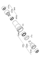
- FIG. 8 is an exploded perspective view schematically showing a configuration of a bearing portion included in the fan device shown in FIG. FIG.
- FIG. 5 is a cross-sectional view schematically showing a configuration of a bearing portion included in the fan device shown in FIG. It is a functional block diagram of the drive control device of the motor which concerns on 4th Embodiment of this invention. It is a flowchart for showing the operation of the bearing part when the lower bearing part deteriorates in the motor provided by the fan device shown in FIG. 18, and the transition of the operation of the bearing movement detection part. It is a flowchart for showing the operation of the bearing part when the upper bearing part deteriorates in the motor provided with the fan device shown in FIG. 18, and the transition of the operation of the bearing movement detection part.
- FIG. 1 is a front view schematically showing a configuration of a fan device 1 including a motor 10 according to the first embodiment of the present invention.
- FIG. 2 is a cross-sectional view schematically showing the configuration of the fan device 1.
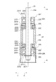
- FIG. 3 is a cross-sectional view schematically showing the configuration of the rotating shaft 23 and the bearing portion 22 included in the fan device 1.
- the arrow a direction is the upper side a and the arrow b direction is the lower side b in the axis x direction.
- the direction away from the axis x is defined as the outer peripheral side c
- the direction toward the axis x is defined as the inner peripheral side d. ..
- the direction shown in FIG. 1 is referred to as the side surface of the motor.
- the direction in which the motor is viewed from the upper side a toward the lower side b is the front surface
- the direction in which the motor is viewed from the lower side b toward the upper side a is the bottom surface.
- the motor 10 is provided in the fan device 1 and has a rotor having a rotating shaft 23 and a stator arranged so as to face each other in the circumferential direction of the rotor. 24 and a pair of bearing portions 22A and 22B that rotatably support the rotating shaft 23, and the pair of bearing portions 22A and 22B include a first bearing 221 and a first bearing 221 that can rotate together with the rotating shaft 23.
- the first bearing 221 When the first bearing 221 is normal, the first bearing 221 rotates together with the rotating shaft 23, and when the first bearing 221 becomes abnormal, the first bearing is provided.
- the second bearing 222 also rotates with the rotating shaft 23.
- the fan device 1 includes an impeller 30 having a plurality of blades 28 on the hub 25, and a casing 40 that covers the outer periphery of the impeller 30 and determines the outer shape of the fan device 1.
- the impeller 30 has a hub 25 arranged in a central portion centered on the axis x inside the casing 40.
- the motor 10 is arranged inside the hub 25 of the impeller 30.
- the motor 10 is, for example, an outer rotor type brushless DC (Direct Current) motor in which the rotating shaft 23, the rotor yoke 26 and the impeller 30 connected to the rotating shaft 23 form a rotor.
- the motor 10 includes a rotating shaft 23, a bearing housing 21, a pair of bearing portions 22A and 22B, a stator 24, a rotor yoke 26, and a magnet 27.
- the rotating shaft 23 is a rod-shaped member arranged with the axis x direction as the longitudinal direction.
- the bearing housing 21 is a hollow tubular body supported by the central portion of the casing 40.
- the bearing housing 21 rotatably supports the rotating shaft 23 via a pair of bearing portions 22A and 22B.
- the bearing housing 21 has a bearing support portion 212 that supports the bearing portion 22A at one end of the cylindrical housing body 211 in the axis x direction and a bearing support portion that supports the bearing portion 22B at the other end of the housing body 211 in the axis x direction. 213 and.
- the bearing support portions 212 and 213 are formed on the inner peripheral surfaces of the housing body 211, respectively.
- the pair of bearing portions 22A and 22B are the bearing portion 22A supported by the bearing support portion 212 provided at one end in the axis x direction of the bearing housing 21 and the axis of the bearing housing 21 as described above. It is a bearing portion 22B supported by a bearing support portion 213 provided at the other end in the x direction.
- the pair of bearing portions 22A and 22B include a first bearing 221 and a second bearing 222, and a coupling portion 223, respectively.
- the second bearing 222 is provided at a position separated from the first bearing 221 in the axis x direction of the rotating shaft 23.
- the first bearing 221 includes a first inner ring 2211, a first outer ring 2212, and a first rolling element 2213.
- the first inner ring 2211 is an annular member having an inner peripheral surface that can be mounted on the outer peripheral surface 23a of the rotating shaft 23.
- the first inner ring 2211 can rotate together with the rotating shaft 23 by being mounted on the outer peripheral surface 23a of the rotating shaft 23.
- the first outer ring 2212 is provided on the outer peripheral side c of the first inner ring 2211.
- the first outer ring 2212 is an annular member coaxial with the first inner ring 2211 and having a diameter larger than that of the first inner ring 2211.
- the first rolling element 2213 is a spherical member arranged between the first inner ring 2211 and the first outer ring 2212. In the first bearing 221, a lubricant is sealed between the first inner ring 2211, the first outer ring 2212, and the first rolling element 2213.
- the second bearing 222 includes a second inner ring 2221, a second outer ring 2222, and a second rolling element 2223.
- the second inner ring 2221 is an annular member having an inner peripheral surface that can be attached to the coupling portion 223. By being attached to the coupling portion 223, the second inner ring 2221 can rotate together with the first outer ring 2212 via the coupling portion 223.
- the second outer ring 2222 is provided on the outer peripheral side c of the second inner ring 2221.
- the second outer ring 2222 is an annular member coaxial with the second inner ring 2221 and having a diameter larger than that of the second inner ring 2221.
- the second rolling element 2223 is a spherical member arranged between the second inner ring 2221 and the second outer ring 2222.
- a lubricant is sealed between the second inner ring 2221, the second outer ring 2222, and the second rolling element 2223.
- the kinematic viscosities of the first bearing 221 and the second bearing 222 differ from each other due to differences in the mechanical friction coefficient of the components used for each and the viscosity of the lubricant.
- the first bearing 221 has, for example, a kinematic viscosity lower than the kinematic viscosity of the second bearing 222.
- the coupling portion 223 includes a first bearing accommodating portion 2231, a second bearing accommodating portion 2232, and a step portion 2233.
- the coupling portion 223 is a step connecting the first bearing accommodating portion 2231 and the second bearing accommodating portion 2232, which are tubular portions having different radial dimensions, and the first bearing accommodating portion 2231 and the second bearing accommodating portion 2232.
- the first outer ring 2212 and the second inner ring 2221 are rotatably connected by the portion 2233.
- the first bearing accommodating portion 2231 has an inner peripheral surface capable of accommodating the first outer ring 2212 of the first bearing 221. Specifically, the first bearing accommodating portion 2231 is formed in a shape and size that can rotate in cooperation with the first outer ring 2212.
- the second bearing accommodating portion 2232 has an inner peripheral surface having a shape and size having a predetermined gap with respect to the outer peripheral surface 23a of the rotating shaft 23. Further, the second bearing accommodating portion 2232 has an outer peripheral surface capable of accommodating the second inner ring 2221 of the second bearing 222. The second bearing accommodating portion 2232 is formed in a shape and size that can rotate in cooperation with the second inner ring 2221.
- the stator 24 is fixed to, for example, the lower side b of the casing 40.
- the stator 24 includes, for example, a stator core 241 formed by laminating a plurality of electromagnetic steel plates, an insulator provided on the stator core, and a coil 242 wound on the stator core 241 via an insulator.
- the rotor yoke 26 is provided on the inner peripheral portion of the hub 25 of the impeller 30, for example.
- the rotor yoke 26 is formed in a substantially tubular shape, for example, for accommodating the magnet 27.
- the rotor yoke 26 may be formed separately from the hub 25 or may be formed integrally with the hub 25.
- the magnet 27 is attached to the inner peripheral surface of the rotor yoke 26.
- the magnet 27 is provided so as to have a predetermined gap with the stator 24 provided on the inner peripheral side d.
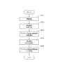
- FIG. 4 is a flowchart for showing the transition of the operation of the bearing portions 22A and 22B of the motor 10 included in the fan device 1.
- the motor 10 starts the rotation of the rotating shaft 23 when the driving current flows (step S11).
- the rotating shaft 23 of the motor 10 is rotatably supported by a pair of bearing portions 22A and 22B mounted on the bearing housing 21. Further, one end of the upper side a of the rotating shaft 23 is connected to the hub 25 of the impeller 30. Therefore, when the motor 10 is driven, the rotating shaft 23 rotates about the axis x, and the impeller 30 also rotates about the axis x accordingly.
- the motor 10 includes a first bearing 221 in which a pair of bearing portions 22A and 22B can rotate together with the rotating shaft 23, and a second bearing 222 that can rotate together with the first bearing 221.
- the pair of bearing portions 22A and 22B have different kinematic viscosities of the first bearing 221 and the second bearing 222. That is, the motor 10 moves among the first bearing 221 and the second bearing 222 due to the difference in kinematic viscosity of the two bearings (first bearing 221 and second bearing 222) provided in the pair of bearing portions 22A and 22B, respectively.
- a bearing having a low viscosity (for example, the first bearing 221) is easier to rotate.
- the first bearing 221 having low kinematic viscosity has a normal operation function. 1
- the inner ring 2211 is supported by the first rolling element 2213 and the first outer ring 2212 and rotates together with the rotating shaft 23.
- the state in which the first inner ring 2211 is supported by the first rolling element 2213 and the first outer ring 2212 and rotates together with the rotating shaft 23 is regarded as a normal state.
- step S12 when the operating function of the first bearing 221 deteriorates or starts to fail in the bearing portions 22A and 22B, the friction coefficient of the first bearing 221 increases (step S12). In this way, the state in which the operating function of the first bearing 221 is deteriorated or malfunctions, an abnormality occurs, and the friction coefficient increases is defined as an abnormal state.
- the rotational torque of the first bearing 221 exceeds the starting torque of the second bearing 222, the rotation of the coupling portion 223 and the second bearing 222 starts (step S13).
- the first inner ring 2211 of the first bearing 221 and the first outer ring 2212 and the first rolling element 2213 are integrally rotated together with the rotating shaft 23.
- the inner peripheral surface of the first bearing accommodating portion 2231 is rotatably connected to the coupling portion 223 together with the first outer ring 2212 of the first bearing 221.
- the second bearing 222 starts rotating (co-rotating) with the rotating shaft 23 via the coupling portion 223.
- step S15 since the second inner ring 2221 of the second bearing 222 is attached to the outer peripheral surface of the second bearing accommodating portion 2232 of the coupling portion 223, it can rotate according to the rotation of the coupling portion 223. Therefore, in the motor 10, the coupling portion 223 and the second bearing 222 rotate together with the rotating shaft 23 (step S15).
- the rotating shaft 23 is formed by the pair of bearing portions 22A and 22B having the first bearing 221 and the second bearing 222 having different kinematic viscositys. Since it is supported, even if the first bearing 221 is in an abnormal state such as deterioration or failure, the operation can be continued without replacing the bearing parts. That is, according to the motor 10 configured as described above and the fan device 1 including the motor 10, the motor 10 is always operated and maintenance work such as parts replacement work is performed, for example, like a fan for cooling a server. The life of the bearing can be extended even in applications where the time is limited.
- FIG. 5 is a schematic view showing a transition between the rotation speed of the motor 10 included in the fan device 1 and the motor current.
- FIG. 5 shows changes in the rotational speed of the motor 10 and the values of the motor current according to the deterioration status of the bearing portions 22A and 22B from the start of operation of the motor 10.
- t0 at the start of operation of the motor 10
- t1 when the first bearing 221 is not in a normal operating state (start of failure of the first bearing 221)
- t2 the first bearing 221 is rotated together with the coupling portion 223.
- the first bearing 221 rotates together with the inner and outer rings
- the motor 10 is operated at a rotation speed: R2 and a motor current value: A1 because the first bearing 221 is operating normally in the period from t0 to t1.
- the rotation speed of the motor 10 decreases from R2 and the motor current value changes from A1 due to the deterioration of the first bearing 221 and the gradual increase in the rotational torque of the first bearing 221. It is rising.
- the rotational torque of the first bearing 221 exceeds the starting torque of the second bearing 222, so that the second bearing 222 operates in the bearing portions 22A and 22B. Therefore, the rotational speed: R1, the motor current. Value: A2.
- the rotating shaft 23 is formed by the pair of bearing portions 22A and 22B having the first bearing 221 and the second bearing 222 having different kinematic viscositys. Since it is supported, for example, by measuring the rotation speed of the motor 10 and the motor current, it is possible to easily recognize which of the first bearing 221 and the second bearing 222 is operating in the bearing portions 22A and 22B. Can be done. That is, according to the motor 10 configured as described above and the fan device 1 including the motor 10, the operating states of the bearing portions 22A and 22B can be easily recognized, so that the bearing portions 22A and 22B can be replaced. The time and life can be predicted.
- the reliability of the bearing can be improved.
- the rotation of the rotating shaft 23 can be transmitted to the second bearing 222 when the first bearing 221 is deteriorated by the coupling portion 223, so that the reliability of the bearing is increased. Can be improved. Further, since the coupling portion 223 does not transmit rotation to the second bearing 222 when the first bearing 221 is operating normally, the reliability of the bearing is improved without causing loss in the bearing portions 22A and 22B. can do.
- the drive control device 3 of the motor 10 functions as a state detection device for detecting the states of the bearing portions 22A and 22B of the motor 10.
- the drive control device 3 has a rotation speed calculation unit 32 as an information acquisition unit that acquires rotation information that is information based on the rotational movement of the motor 10, and a bearing unit 22A, based on the rotation information acquired by the rotation speed calculation unit 32.
- a bearing abnormality determination unit 35 is provided as a state detection unit for detecting the state of the rotational movement of 22B.
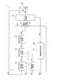
- FIG. 6 is a functional block diagram of the drive control device 3 of the motor 10 according to the embodiment of the present invention.
- the drive control device 3 of the motor 10 includes a speed command analysis unit 31, a rotation speed calculation unit 32, a PWM (Pulse Width Modulation) command unit 33, a PWM signal generation unit 34, and a bearing abnormality determination unit 35.
- the drive control device 3 is, for example, an information processing device such as an MCU (MicroControllerUnit) capable of executing various computer programs including a program for realizing the following functional blocks by the drive control device 3 according to the present invention. It is realized by a storage device such as a ROM (Read Only Memory) that stores a computer program or data at the time of program execution.
- the ROM also stores information on predetermined values of rotation information used in processing by the bearing abnormality determination unit 35, which will be described later.
- the speed command analysis unit 31 receives the speed command signal Sc of the motor 10 from an external device (not shown) such as a server control unit, and generates a target rotation speed signal S1 for giving an instruction to the PWM command unit 33.
- the rotation speed calculation unit 32 is the first hall signal Sh1 (information on the rotation speed) acquired by the hall sensor H1 attached to the motor 10 and provided to detect the rotation speed of the rotor (rotational shaft 23 or impeller 30). ) Is acquired as the actual rotation speed information of the rotor, and the rotation speed of the rotor is calculated.
- the rotation speed calculation unit 32 outputs the rotation speed signal S2 to the PWM command unit 33 and the bearing abnormality determination unit 35. Further, the rotation speed calculation unit 32 outputs the calculated rotation speed of the rotor to an external device as an FG (Frequency Generator) signal.
- FG Frequency Generator
- the PWM command unit 33 generates a PWM signal signal S3 that is generated based on the target rotation speed signal S1 output from the speed command analysis unit 31 and the rotation speed signal S2 output from the rotation speed calculation unit 32. Output to unit 34.
- the PWM setting instruction signal S3 is a signal for instructing the PWM signal setting generated by the PWM signal generation unit 34, that is, the duty ratio of the PWM signal required to drive the motor 10 at a desired rotation speed.
- the PWM signal generation unit 34 generates and outputs a drive control signal Sd that controls the motor drive unit 2, that is, a PWM signal S4 having a desired duty ratio, based on the PWM setting instruction signal S3 output by the PWM command unit 33. ..
- the motor drive unit 2 drives the motor 10 based on the drive control signal Sd. Further, the bearing abnormality determination unit 35 acquires the current signal S5, which is information on the motor current flowing through the motor drive unit 2, which is an example of the rotation information of the motor.
- the bearing abnormality determination unit 35 is an information acquisition unit that acquires rotational information that is information based on the rotational motion of the motor 10, and a state of rotational motion of the bearing portions 22A and 22B based on the rotational information acquired by this information acquisition unit. Functions as a state detector to detect. Specifically, the bearing abnormality determination unit 35 has either the first bearing 221 or the second bearing 222 in the bearing units 22A and 22B based on at least one of the rotation speed signal S2 and the current signal S5, which are rotation information. It is determined whether or not the bearings are rotating together with the rotating shaft 23, and whether or not the first bearing 221 of the bearing portions 22A and 22B is in an abnormal state such as deterioration or failure is detected. When the bearing abnormality determination unit 35 detects an abnormality in the bearing units 22A and 22B, the bearing abnormality determination unit 35 outputs information indicating an abnormality state of the bearing units 22A and 22B to an external device as an abnormality notification signal Sa.
- FIG. 7 is a flowchart for showing an example of the state detection processing of the bearing portions 22A and 22B by the drive control device 3 of the motor 10.
- the bearing abnormality determination unit 35 has a rotation speed signal S2 which is information on the rotation speed of the motor as rotation information, and the motor drive unit 2
- the state of the bearing portions 22A and 22B is detected based on the current signal S5, which is information on the motor current flowing through the bearing.
- the bearing abnormality determination unit 35 shows a predetermined value of the rotation speed of the motor, for example, FIG. 5, based on the rotation speed signal S2 output by the rotation speed calculation unit 32. It is determined whether or not it is R1 or more (S101).
- step S101 NO
- the bearing abnormality determination unit 35 determines the motor current flowing through the motor 10 based on the current signal S5 which is information about the motor current flowing through the motor driving unit 2. Is less than a predetermined value, for example, A2 shown in FIG. 5 (step S102).
- step S102 When the motor current flowing through the motor 10 exceeds a predetermined value (step S102: NO), the bearing abnormality determination unit 35 determines that the first bearing 221 of the bearing portions 22A and 22B is in an abnormal state of deterioration (step S103). ). As shown in FIG. 4, when the first bearing 221 deteriorates, the rotational torque of the first bearing 221 gradually increases, so that the rotational speed decreases from the normal state, and the motor current also changes from the normal state. To rise. Therefore, the bearing abnormality determination unit 35 detects that both the rotation speed of the motor 10 and the motor current have changed from normal values, and detects an abnormal state of the bearing units 22A and 22B, that is, the life. be able to.
- step S101 when the rotation speed of the motor 10 is equal to or higher than a predetermined value (step S101: YES) or when the motor current of the motor 10 is less than a predetermined value (step S102: YES), the bearing abnormality determination unit 35 , It is determined that the first bearing 221 of the bearing portions 22A and 22B is operating normally (step S104).
- FIG. 8 is a flowchart for showing a modified example of the state detection process of the bearing portions 22A and 22B by the drive control device 3 of the motor 10.
- the bearing abnormality determination unit 35 uses the rotation speed signal S2, which is the rotation speed information of the motor, or the motor drive as rotation information.
- the state of the bearing portions 22A and 22B is detected based on any information of the current signal S5, which is information regarding the motor current flowing through the portion 2.
- the bearing abnormality determination unit 35 shows a predetermined value of the rotation speed of the motor, for example, FIG. 5, based on the rotation speed signal S2 output by the rotation speed calculation unit 32. It is determined whether or not it is R1 or more (step S201).
- step S201 When the rotation speed of the motor 10 is equal to or higher than a predetermined value (step S201: YES), the bearing abnormality determination unit 35 moves the motor flowing through the motor 10 based on the current signal S5 which is information about the motor current flowing through the motor driving unit 2. It is determined whether or not the current is a predetermined value, for example, less than A2 shown in FIG. 5 (step S202).
- the bearing abnormality determination unit 35 is the bearing unit 22A. It is determined that the first bearing 221 of 22B is in an abnormal state of deterioration (S203).
- the bearing abnormality determination unit 35 detects that both the rotation speed of the motor 10 and the motor current have changed from the normal values, and the bearing units 22A and 22B. Abnormal state, that is, the life span can be detected.
- step S202 when the motor current of the motor 10 is less than a predetermined value (step S202: YES), the bearing abnormality determination unit 35 determines that the first bearing 221 of the bearing units 22A and 22B is operating normally. (Step S204).
- the rotating shaft 23 is supported by a pair of bearing portions 22A and 22B having a first bearing 221 and a second bearing 222 having different kinematic viscositys. Since the operating state of the bearing portions 22A and 22B is determined based on the rotation information of the motor 10, for example, the rotation speed of the motor 10 and at least one of the motor currents, the bearing portion is determined. Which of the first bearing 221 and the second bearing 222 is operating in the 22A and 22B, that is, the operating state of the bearing portions 22A and 22B can be easily determined. That is, according to the drive control device 3 of the motor 10 configured as described above, the operating state of the bearing portions 22A and 22B of the motor 10 can be easily determined, so that it is time to replace the bearing portions 22A and 22B. , Life can be predicted.
- FIG. 9 is a cross-sectional view schematically showing the configuration of the rotating shaft 23 and the bearing portions 22Ab and 22Bb included in the motor according to the second embodiment of the present invention.
- the pair of bearing portions 22Ab and 22Bb included in the motor according to the second embodiment has the bearing portion 22Ab of the bearing housing 21b, similarly to the pair of bearing portions 22A and 22B described above. It is supported by a bearing support portion 212b provided at one end in the axis x direction, and a bearing portion 22Bb is supported by a bearing support portion 213b provided at the other end of the bearing housing 21b in the axis x direction.
- the first bearing 221b and the second bearing 222b of the bearing portions 22Ab and 22Bb are in a direction perpendicular to the axis x direction of the rotating shaft 23. It differs from the pair of bearing portions 22A and 22B described above in that they are arranged at positions. That is, in the pair of bearing portions 22Ab and 22Bb, the second bearing 222b is provided on the radial outside of the first bearing 221b, that is, on the outer peripheral side c of the first bearing 221b.
- the pair of bearing portions 22Ab and 22Bb have the first outer ring 2212b of the first bearing 221b and the second inner ring 2221b of the second bearing 222b. It is different from the pair of bearing portions 22A and 22B described above in that they are in contact with each other.
- the pair of bearing portions 22Ab and 22Bb are configured so that the first outer ring 2212b of the first bearing 221b and the second inner ring 2221b of the second bearing 222b are in contact with each other and can rotate together with the first outer ring 2212. It differs from the pair of bearing portions 22A and 22B described above in that it does not have a coupling portion 223 connecting the second inner ring 2221.
- the rotating shaft 23 is formed by the pair of bearing portions 22Ab and 22Bb having the first bearing 221b and the second bearing 222b having different kinematic viscosity. Since it is supported, even if the first bearing 221b deteriorates or fails, the operation can be continued without replacing the bearing parts. That is, according to the motor and fan device including the bearing portions 22Ab and 22Bb configured as described above, for example, like a cooling fan of a server, the motor and fan device are always operated and maintenance work such as parts replacement work is performed. Bearing life can be extended even in limited time applications.
- the reliability of the bearing can be improved.
- the fan device 1C including the motor 10C of the third embodiment according to the present invention will be described.
- the same reference numerals are given to the same configurations as those of the motor 10 described above, and the description thereof will be omitted.
- FIG. 10 is a cross-sectional view schematically showing the configuration of the fan device 1C.
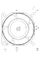
- FIG. 11 is a front view schematically showing the configuration of the motor 10C.
- FIG. 12 is a cross-sectional view schematically showing the configuration of the motor 10C.
- FIG. 13 is a cross-sectional view schematically showing the configuration of the rotating shaft 23C and the bearing portions 22AC and 22BC included in the fan device 1C.
- the motor 10C is provided in the fan device 1C, and has a rotor having a rotating shaft 23C and a stator arranged so as to face each other in the circumferential direction of the rotor. 24C, a pair of bearing portions 22AC, 22BC having a first bearing 221C that rotatably supports the rotating shaft 23C and is rotatable together with the rotating shaft 23C, and a second bearing 222C that is rotatable together with the first bearing 221C.
- a bearing motion detecting section 37 for detecting the motion of the bearing sections 22AC and 22BC is provided, and the first bearing 221C is provided on the outer peripheral side c of the first inner ring 2211C and the first inner ring 2211C which can rotate together with the rotating shaft 23C. It has a first outer ring 2212C and a first rolling element 2213C arranged between the first inner ring 2211C and the first outer ring 2212C, and the second bearing 222C has a second bearing 222C that can rotate together with the first outer ring 2212C.
- the bearing motion detection unit 37 outputs bearing motion information according to the rotational motion of the first outer ring 2212C.
- the configuration and operation of the fan device 1C including the motor 10C will be specifically described.
- the fan device 1C includes an impeller 30C having a plurality of blades 28C on the hub 25C, and a casing 40C that covers the outer periphery of the impeller 30C and determines the outer shape of the fan device 1C.
- the impeller 30C has a hub 25C arranged in a central portion centered on an axis x inside the casing 40C.
- the motor 10C is arranged inside the hub 25C of the impeller 30C.
- the motor 10C is, for example, an outer rotor type brushless DC (Direct Current) motor in which a rotary shaft 23C, a rotor yoke 26C connected to the rotary shaft 23C, and an impeller 30C form a rotor.
- the motor 10C includes a rotating shaft 23C, a bearing housing 21C, a pair of bearing portions 22AC, 22BC, a stator 24C, a rotor yoke 26C, a magnet 27C, a first substrate 291C, a second substrate 292C, and a rotor motion detection sensor (an example of a rotor motion detection unit). ) 36C and a bearing motion detection unit 37.
- DC Direct Current
- the rotating shaft 23C is a rod-shaped member arranged with the axis x direction as the longitudinal direction.
- the bearing housing 21C is a hollow tubular body supported by the central portion of the casing 40C.
- the bearing housing 21C rotatably supports the rotating shaft 23C via a pair of bearing portions 22AC and 22BC.
- the bearing housing 21C has a bearing support portion 212C that supports the bearing portion 22AC at one end of the cylindrical housing body 211C in the axis x direction and a bearing support portion that supports the bearing portion 22BC at the other end of the housing body 211C in the axis x direction. It is equipped with 213C.
- the bearing support portions 212C and 213C are each formed on the inner peripheral surface of the housing body 211C.
- the pair of bearing portions 22AC and 22BC are the bearing portion 22AC supported by the bearing support portion 212C provided at one end of the bearing housing 21C in the axis x direction and the axis of the bearing housing 21C as described above. It is a bearing portion 22BC supported by a bearing support portion 213C provided at the other end in the x direction.
- the pair of bearing portions 22AC and 22BC include a first bearing 221C, a second bearing 222C, and a coupling portion 223C, respectively.
- the second bearing 222C is provided at a position separated from the first bearing 221C in the axis x direction of the rotating shaft 23C.
- the first bearing 221C includes a first inner ring 2211C, a first outer ring 2212C, and a first rolling element 2213C.
- the first inner ring 2211C is an annular member having an inner peripheral surface that can be mounted on the outer peripheral surface 23a of the rotating shaft 23C.
- the first inner ring 2211C can rotate together with the rotating shaft 23C by being mounted on the outer peripheral surface 23a of the rotating shaft 23C.
- the first outer ring 2212C is provided on the outer peripheral side c of the first inner ring 2211C.
- the first outer ring 2212C is an annular member coaxial with the first inner ring 2211C and having a diameter larger than that of the first inner ring 2211C.
- the first rolling element 2213C is a spherical member arranged between the first inner ring 2211C and the first outer ring 2212C.
- a lubricant is sealed between the first inner ring 2211C, the first outer ring 2212C, and the first rolling element 2213C.
- the second bearing 222C includes a second inner ring 2221C, a second outer ring 2222C, and a second rolling element 2223C.
- the second inner ring 2221C is an annular member having an inner peripheral surface that can be attached to the coupling portion 223C.
- the second inner ring 2221C can rotate together with the first outer ring 2212C via the coupling portion 223C by being attached to the coupling portion 223C.
- the second outer ring 2222C is provided on the outer peripheral side c of the second inner ring 2221C.
- the second outer ring 2222C is an annular member coaxial with the second inner ring 2221C and having a diameter larger than that of the second inner ring 2221C.
- the second rolling element 2223C is a spherical member arranged in plurality between the second inner ring 2221C and the second outer ring 2222C.
- a lubricant is sealed between the second inner ring 2221C, the second outer ring 2222C, and the second rolling element 2223C.
- the kinematic viscosities of the first bearing 221C and the second bearing 222C may differ from each other due to differences in the mechanical friction coefficient of the components used for each and the viscosity of the lubricant.
- the first bearing 221C has, for example, a kinematic viscosity lower than the kinematic viscosity of the second bearing 222C.
- the kinematic viscosity of the first bearing 221C may be the same as the kinematic viscosity of the second bearing 222C, or may be higher than the kinematic viscosity of the second bearing 222C.
- the coupling portion 223C includes a first bearing accommodating portion 2231C, a second bearing accommodating portion 2232C, and a step portion 2233C.
- the coupling portion 223C is a step connecting the first bearing accommodating portion 2231C and the second bearing accommodating portion 2232C, which are tubular portions having different radial dimensions, and the first bearing accommodating portion 2231C and the second bearing accommodating portion 2232C.
- the first outer ring 2212C and the second inner ring 2221C are rotatably connected by the portion 2233C.
- the first bearing accommodating portion 2231C has an inner peripheral surface capable of accommodating the first outer ring 2212C of the first bearing 221C. Specifically, the first bearing accommodating portion 2231C is formed in a shape and size that can rotate in cooperation with the first outer ring 2212C.
- the second bearing accommodating portion 2232C has an inner peripheral surface having a shape and size having a predetermined gap with respect to the outer peripheral surface 23a of the rotating shaft 23C. Further, the second bearing accommodating portion 2232C has an outer peripheral surface capable of accommodating the second inner ring 2221C of the second bearing 222C. The second bearing accommodating portion 2232C is formed in a shape and size that can rotate in cooperation with the second inner ring 2221C.
- the stator 24C is fixed to, for example, the lower side b of the casing 40C.
- the stator 24C includes, for example, a stator core 241C formed by laminating a plurality of electromagnetic steel plates, a coil 242C wound on the stator core 241C, and an insulator 243C provided on the stator core 241C.
- the rotor yoke 26C is provided on the inner peripheral portion of the hub 25C of the impeller 30C, for example.
- the rotor yoke 26C is formed in a substantially tubular shape, for example, to accommodate the magnet 27C.
- the rotor yoke 26C may be formed separately from or integrally with the hub 25C.
- the magnet 27C is attached to the inner peripheral surface of the rotor yoke 26C.
- the magnet 27C is provided so as to have a predetermined gap with the stator 24C provided on the inner peripheral side d.
- the first substrate 291C is provided on at least one of the bearing portions 22AC and 22BC, for example, on the outer peripheral side c of the bearing portion 22AC on the upper side a corresponding to one end of the stator 24C in the axis x direction.
- the first substrate 291C is a plate-shaped substrate formed in a substantially arc shape on a part of the outer peripheral side c of the bearing portion 22AC.
- the bearing motion detection sensor 372 of the bearing motion detection unit 37 is mounted on the upper side a of the first substrate 291C.
- the second substrate 292C is provided on at least the other of the bearing portions 22AC and 22BC, for example, on the outer peripheral side c of the bearing portion 22BC on the lower side b corresponding to the other end in the axial x direction of the stator 24C.
- the second substrate 292C is arranged so as to sandwich the stator 24C together with the first substrate 291C in the direction parallel to the axis x of the rotating shaft 23C of the rotor.
- the second substrate 292C is a substrate whose outer shape is formed in a substantially disk shape on the outer peripheral side c of the bearing portion 22BC.
- a rotor motion detection sensor 36C as a rotor motion detection unit is mounted on the upper side a of the second substrate 292C.
- the rotor motion detection sensor 36C is mounted on the upper side a of the second substrate 292C as described above.
- the rotor motion detection sensor 36C is arranged in the magnetic field range of the magnet 27C provided on the inner peripheral surface of the hub 25C of the impeller 30C constituting the rotor, for example, on the inner peripheral side d of the magnet 27C.
- the rotor motion detection sensor 36C is a first hole signal (an example of rotor motion information) as rotor motion information, which is a position signal corresponding to the rotation motion of the magnet 27C as the magnet 27C attached to the rotor rotates. ) Is output.
- the rotor operation information is, for example, information according to the rotation speed of the rotor, such as information on the rotation speed or rotation speed of the rotor, and specifically, the above-mentioned first hole signal or first hole. It is the information of the rotation speed of the rotor calculated from the signal (rotor rotation speed signal).
- the number of rotor motion detection sensors 36C is not limited to this embodiment.
- the bearing motion detection unit 37 is composed of a bearing motion detection magnet 371 and a bearing motion detection sensor 372.
- the bearing motion detection magnet 371 covers the outer peripheral side c of the first outer ring 2212C, for example, the outer peripheral side c of the first outer ring 2212C, and is rotatable together with the first outer ring 2212C on the outer peripheral side of the first bearing accommodating portion 2231C. It is provided in c. By arranging the bearing motion detection magnet 371 in this way, the bearing motion detection magnet 371 can rotate together with the first outer ring 2212C.
- the bearing motion detection sensor 372 is mounted on the magnetic field range of the bearing motion detection magnet 371, specifically, on the upper side a of the first substrate 291C located on the outer peripheral side c of the bearing motion detection magnet 371.
- the bearing motion detection sensor 372 uses a hole signal corresponding to the rotation motion of the bearing motion detection magnet 371 as the bearing motion detection magnet 371 attached to the coupling portion 223C rotating together with the first outer ring 2212C rotates.
- the second hole signal as a certain bearing operation information is output.
- the bearing operation information is, for example, information on the rotation speed or rotation speed of the bearing, and specifically, the rotation speed of the first bearing 221C calculated from the second hole signal or the second hole signal. Corresponding information (bearing speed signal).
- the number of bearing motion detection units 37 is not limited to this embodiment.
- the drive control device 3C of the motor 10C functions as a state determination device for determining the states of the bearing portions 22AC and 22BC of the motor 10C.
- the drive control device 3C uses the bearing operation information output by the bearing operation detection sensor 372 of the bearing operation detection unit 37 of the motor 10C and the rotor operation information output by the rotor operation detection sensor 36C to rotate the first bearing 221C.
- the bearing abnormality determination unit 35C is provided as a state determination unit for determining the state of. As will be described later, the bearing abnormality determination unit 35C determines whether or not the first bearing 221C has deteriorated based on the bearing operation information. Further, the bearing abnormality determination unit 35C determines whether or not the first bearing has failed based on the bearing operation information and the rotor operation information.
- the drive control device 3C of the motor 10C that functions as the motor state determination device will be described.
- FIG. 14 is a functional block diagram of the drive control device 3C of the motor 10C according to the third embodiment of the present invention.
- the drive control device (an example of the state determination device) 3C of the motor 10C includes a speed command analysis unit 31C, a first rotation speed calculation unit 321C, a second rotation speed calculation unit 322C, and PWM (Pulse Width Modulation).
- a command unit 33C, a PWM signal generation unit 34C, and a bearing abnormality determination unit (an example of a state determination unit) 35C are provided.
- the drive control device 3C is, for example, an information processing device such as an MCU (MicroControllerUnit) capable of executing various computer programs including a program for realizing the following functional blocks by the drive control device 3C according to the present invention. It is realized by a storage device such as a ROM (Read Only Memory) that stores a computer program or data at the time of program execution. Further, in the ROM, it is determined that the threshold value used when determining that the first bearing 221C used in the processing by the bearing abnormality determination unit 35C described later is deteriorated and that the first bearing 221C is out of order.
- Bearing rotation speed signal (example of bearing operation information) S5 and rotor rotation speed signal (example of rotor operation information) Information on the ratio of S2 is also stored.
- the speed command analysis unit 31C receives the speed command signal Sc of the motor 10C from an external device (not shown) such as a server control unit, and generates a target rotation speed signal S1 for giving an instruction to the PWM command unit 33C.
- the first rotation speed calculation unit 321C is the first hole signal Sh1 (related to the rotation speed of the rotor) acquired by the rotor operation detection sensor 36C attached to the motor 10C and provided to detect the rotation speed of the rotor magnet 27C. Information (an example of rotor operation information) is acquired, the rotation speed of the rotor is calculated based on the first hall signal Sh1, and the rotor rotation speed signal S2 is output.
- the first rotation speed calculation unit 321C outputs the rotor rotation speed signal S2 to the PWM command unit 33C and the bearing abnormality determination unit 35C. Further, the first rotation speed calculation unit 321C outputs the calculated rotation speed of the rotor to an external device as an FG (Frequency Generator) signal FG.
- FG Frequency Generator
- the second rotation speed calculation unit 322C is a second hole acquired from a bearing operation detection unit 37 provided for detecting the rotation speed of the first outer ring 2212C of the first bearing 221C of the bearing units 22AC and 22BC in the motor 10C.
- the signal Sh2 (information on the rotation speed of the first outer ring 2212C of the first bearing 221C) is acquired, the rotation speed of the first outer ring 2212C is calculated based on the second Hall signal Sh2, and the bearing rotation speed signal S5 is output. ..
- the second rotation speed calculation unit 322C outputs the bearing rotation speed signal S5 to the PWM command unit 33C and the bearing abnormality determination unit 35C.
- the PWM command unit 33C generates a PWM setting instruction signal S3 based on the target rotation speed signal S1 output from the speed command analysis unit 31C and the rotor rotation speed signal S2 output from the first rotation speed calculation unit 321C. Output to the PWM signal generation unit 34C.
- the PWM setting instruction signal S3 is a signal for instructing the setting of the PWM signal generated by the PWM signal generation unit 34C, that is, the duty ratio of the PWM signal required to drive the motor 10C at a desired rotation speed.
- the PWM signal generation unit 34C generates and outputs a drive control signal Sd that controls the motor drive unit 2C, that is, a PWM signal S4 having a desired duty ratio, based on the PWM setting instruction signal S3 output by the PWM command unit 33C. ..
- the motor drive unit 2C drives the motor 10C based on the drive control signal Sd.
- the bearing abnormality determination unit 35C determines the rotational motion state of the bearing units 22AC and 22BC based on the rotor operation information calculated by the first rotation speed calculation unit 321C and the bearing operation information calculated by the second rotation speed calculation unit 322C. It functions as a state judgment unit for judgment.
- the bearing abnormality determination unit 35C is the bearing unit 22AC.
- 22BC determines that the second bearing 222C is rotating together with the rotating shaft 23C.
- the bearing abnormality determination unit 35C determines the first bearing 221C of the bearing units 22AC and 22BC by comparing the bearing operation information (for example, the bearing rotation speed signal S5) and the rotor operation information (for example, the rotor rotation speed signal S2). Detects whether or not an abnormality such as deterioration or failure has occurred. Specifically, the bearing abnormality determination unit 35C is a case where the first outer ring 2212C is rotating by comparing the bearing operation information and the rotor operation information, and the rotation of the rotor with respect to the rotation speed of the first outer ring 2212C. When the ratio of the numbers is less than a predetermined value, it is determined that the first bearing 221C has deteriorated (functional deterioration).
- the bearing abnormality determination unit 35C compares the bearing operation information with the rotor operation information, and when the ratio of the rotation speed of the rotor to the rotation speed of the first outer ring 2212C is equal to or higher than a predetermined value, the first bearing It is determined that the abnormal state of the 221C, that is, the deterioration has progressed, and the rotating shaft 23C and the first bearing 221C are stuck, that is, failed.
- the bearing abnormality determination unit 35C outputs the detected state information of the bearing units 22AC and 22BC to an external device as an abnormality notification signal Sa.
- the bearing abnormality determination unit 35C may determine deterioration or failure of the first bearing 221C by using the rotor operation information and the bearing operation information.
- the bearing abnormality determination unit 35C may use, for example, the first hole signal Sh1 or the FG signal FG for processing instead of the rotor rotation speed signal S2. Further, the bearing abnormality determination unit 35C may use, for example, the second hole signal Sh2 for processing instead of the bearing rotation speed signal S5.
- FIG. 15 is a flowchart for showing the operation of the bearing portion and the transition of the operation of the bearing motion detection unit 37 in the motor 10C included in the fan device 1C.
- FIG. 16 is a flowchart for showing an example of the state detection processing of the bearing portions 22AC and 22BC by the drive control device 3C of the motor 10C.
- FIG. 17 shows (a) an FG signal FG as rotor operation information based on the first hole signal Sh1 and (b) a second bearing 221C in a state in which the first bearing 221C is normally operating in the motor 10C included in the fan device 1C.
- Bearing rotation speed signal S5 as bearing operation information based on Hall signal Sh2
- Bearing rotation speed signal S5 as bearing operation information based on second Hall signal Sh2 in a state where the first bearing 221C is deteriorated
- the rotation of the rotating shaft 23C starts when the driving current flows (step S310).
- the rotating shaft 23C of the motor 10C is rotatably supported by a pair of bearing portions 22AC and 22BC mounted on the bearing housing 21C. Further, one end of the upper side a of the rotating shaft 23C is connected to the hub 25C of the impeller 30C. Therefore, when the motor 10C is driven, the rotating shaft 23C rotates about the axis x, and the impeller 30C also rotates about the axis x accordingly.
- the motor 10C includes a first bearing 221C in which a pair of bearing portions 22AC and 22BC can rotate together with the rotating shaft 23C, and a second bearing 222C that can rotate together with the first bearing 221C.
- first bearing 221C in which a pair of bearing portions 22AC and 22BC can rotate together with the rotating shaft 23C
- second bearing 222C that can rotate together with the first bearing 221C.
- the first inner ring 2211C of the first bearing 221C and the outer peripheral surface 23a of the rotating shaft 23C are in contact with each other, the first inner ring 2211C and the rotating shaft 23C rotate together.
- the first outer ring 2212C is in contact with the first bearing accommodating portion 2231C of the coupling portion 223C.
- the second inner ring 2221C is in contact with the second bearing accommodating portion 2232C of the coupling portion 223C. Therefore, in the bearing portions 22AC and 22BC, when the first bearing 221C deteriorates or fails and the first inner ring 2211C and the first outer ring 2212C rotate integrally, the second bearing 222C rotates together with the rotating shaft 23C.
- the first bearing 221C having low kinematic viscosity has a normal operating function under normal conditions (predetermined time after operation).
- the first inner ring 2211C is supported by the first rolling element 2213C and the first outer ring 2212C and rotates together with the rotating shaft 23C.
- the rotor motion detection sensor 36C outputs a pulse corresponding to the rotation motion as shown in FIG. 17A when the rotor is rotating at a predetermined rotation speed, for example.
- step S312 Since the bearing motion detection magnet 371 does not rotate, the second hole signal Sh2 output from the bearing motion detection sensor 372 is output as a constant High or Low signal instead of a pulse signal, as shown in FIG. 17 (b). (Step S312).
- the friction coefficient of the first bearing 221C increases (step S320).
- the coupling portions 223C and the second bearing 222C start to rotate (step S330).
- the first inner ring 2211C of the first bearing 221C, the first outer ring 2212C and the first rolling element 2213C are integrally rotated together with the rotating shaft 23C.
- the rotation of the first bearing 221C is performed according to the deterioration or failure status.
- the torque increases, and the first outer ring 2212C rotates together with the first inner ring 2211C. Therefore, the coupling portion 223C that can rotate together with the first outer ring 2212C and the first outer ring 2212C also rotates together with the first outer ring 2212C. Further, the bearing motion detection magnet 371 attached to the outer peripheral side c of the coupling portion 223C also starts rotating (step S331).
- the first bearing 221C continues to rotate at a ratio different from that of the rotor. That is, in the first bearing 221C, the rotation of the first outer ring 2212C is rotating at a low rotation speed with respect to the rotation shaft 23C (rotor) and is not synchronized with the rotation speed of the rotor. Therefore, from the bearing motion detection sensor 372. As shown in FIG. 17 (c), the output second hole signal Sh2 is output at a cycle different from that of the FG signal FG shown in FIG. 17 (a) (step S332).
- the inner peripheral surface of the first bearing accommodating portion 2231C is rotatably connected to the coupling portion 223C together with the first outer ring 2212C of the first bearing 221C.
- the rotational torque of the first bearing 221C becomes the second bearing 222C.
- the second bearing 222C starts rotating together with the rotating shaft 23C via the coupling portion 223C.
- the second inner ring 2221C of the second bearing 222C is attached to the outer peripheral surface of the second bearing accommodating portion 2232C of the coupling portion 223C as described above, and can rotate according to the rotation of the coupling portion 223C. .. Therefore, in the motor 10C, the coupling portion 223C and the second bearing 222C rotate together with the rotating shaft 23C (step S350).
- the rotation speeds of the first inner ring 2211C, the first rolling element 2213C, and the first outer ring 2212C in the first bearing 221C Gradually rises and finally becomes one with the rotating shaft 23C and rotates at the same rotation speed as the rotating shaft 23C. Therefore, the coupling portion 223C that can rotate together with the first outer ring 2212C and the first outer ring 2212C also rotates together with the first outer ring 2212C at the same rotation speed as the rotation shaft 23C.
- the rotation speed of the bearing operation detection magnet 371 attached to the outer peripheral side c of the coupling portion 223C also increases in the same manner as the rotation speed of the first outer ring 2212C, and rotates at the same rotation speed as the rotation shaft 23C (step). S351). That is, in the first bearing 221C, since the rotation of the first outer ring 2212C is synchronized with the rotation shaft 23C (rotor), the frequency of the second Hall signal Sh2 output from the bearing motion detection sensor 372 increases. As shown in FIG. 17 (d), the FG signal FG shown in FIG. 17 (a) is output at a frequency substantially the same as that of the FG signal FG (step S352).
- FIG. 16 is a flowchart for showing an example of the state detection processing of the bearing portions 22AC and 22BC by the drive control device 3C of the motor 10C.
- the bearing abnormality determination unit 35C is the case where the first outer ring 2212C is rotating as described above, and the first outer ring When the ratio of the rotation speed of the rotor to the rotation speed of the 2212C is less than a predetermined value, it is determined that the first bearing 221C has deteriorated (functional deterioration).
- the bearing abnormality determination unit 35C when the ratio of the rotation speed of the rotor to the rotation speed of the first outer ring 2212C is equal to or higher than a predetermined value, the deterioration of the first bearing 221C progresses, and the rotating shaft 23C and the first bearing It is determined that the 221C is stuck, that is, it is out of order.
- the second hole signal Sh2 output from the bearing operation detection unit 37 is used as the bearing operation information.
- the FG signal FG is used as the rotor operation information.
- the bearing abnormality determination unit 35C determines whether or not the second Hall signal Sh2 has the pulse output waveform shown in FIG. 17C or FIG. 17D via the second rotation speed calculation unit 322C (). Step S3101).
- the bearing abnormality determination unit 35C sends the second hole signal Sh2. Based on this, it is determined that the first bearing 221C is normal in the bearing portions 22AC and 22BC of the motor 10C (a state in which the first inner ring 2211C rotates with the rotating shaft 23C and the first outer ring 2212C does not rotate) (step S3102). ).
- the bearing abnormality determination unit 35C compares the second Hall signal Sh2 with the FG signal FG, and determines whether or not the ratio of the rotation speed of the first outer ring to the rotation speed of the rotor is a predetermined value (YES). Step S3103).
- the first bearing 221C deteriorates, the rotational torque of the first bearing 221C gradually increases, so that the period of the pulse signal of the second hole signal Sh2 approaches the period of the pulse signal like the FG signal FG.
- the rotation speed of the first bearing 221C approaches a predetermined rotation speed which is the actual rotation speed of the motor 10C.
- step S3103 When the period of the second hole signal Sh2 is not a pulse output waveform having a predetermined ratio as compared with the period of the FG signal FG as shown in FIG. 17C (step S3103: NO), the bearing abnormality determination unit 35C Is a deteriorated state in which the first outer ring 2212C is rotating, but the rotation is not synchronized with the rotation of the rotating shaft 23C (rotor), so that the first bearing 221C is rotating at less than a predetermined rotation speed. (Step S3104).
- the bearing abnormality determination unit 35C in the first bearing 221C the rotation of the first outer ring 2212C is synchronized with the rotation of the rotating shaft 23C (rotor) (the first bearing 221C has the same predetermined value as the rotating shaft 23C).
- step S3105 It is determined that the bearing is rotating at the number of rotations), and it is determined that the first inner ring 2211C, the first outer ring 2212C, and the first rolling element 2213C of the first bearing 221C are in a failed state in which they are stuck (step S3105).
- the first bearing 221C The second hole signal Sh2 can be output from the bearing operation detection unit 37 that detects the operation status of the first outer ring 2212C. Further, according to the drive control device 3C of the motor 10C, the operating state of the bearing portions 22AC and 22BC is determined from the bearing rotation speed signal S5 based on the second hole signal Sh2 output from the motor 10C.
- a fan device 1D including the motor 10D according to the fourth embodiment of the present invention will be described.
- the same reference numerals are given to the same configurations as those of the motors 10 and 10C described above, and the description thereof will be omitted.
- the motor 10D can rotate the rotor having the rotating shaft 23D, the stator 24D arranged so as to face each other in the circumferential direction of the rotor, and the rotating shaft 23D. It is provided with a pair of bearing portions 22AD and 22BD that support the bearings.
- the pair of bearing portions 22AD and 22BD are the first bearings 221AD and 221BD that can rotate together with the rotating shaft 23D, the second bearings 222AD and 222BD that can rotate together with the first bearings 221AD and 221BD, and the first bearings 221AD and 221BD.
- the coupling portions 223AD and 223BD which are coupled to the two bearings 222AD and 222BD so as to rotate in conjunction with each other, are respectively provided, and the coupling portions 223AD and 223BD of the pair of bearing portions 22AD and 22BD, respectively, are interlocked with each other. It is connected so as to rotate.
- the configuration and operation of the fan device 1D including the motor 10D will be specifically described.
- the fan device 1D includes an impeller 30D having a plurality of blades 28D on the hub 25D, and a casing 40D that covers the outer circumference of the impeller 30D and determines the outer shape of the fan device 1D.
- the hub 25D is arranged in the central portion centered on the axis x inside the casing 40D.
- the motor 10D is arranged inside the hub 25D of the impeller 30D.
- the motor 10D is, for example, an outer rotor type brushless DC (Direct Current) motor in which a rotating shaft 23D, a rotor yoke 26D connected to the rotating shaft 23D, and an impeller 30D constitute a rotor.
- the motor 10D includes a rotating shaft 23D, a bearing housing 21D, a pair of bearing portions 22AD, 22BD, a stator 24D, a rotor yoke 26D, a magnet 27D, a substrate 29D, a rotor motion detection sensor (an example of a rotor motion detection section) 36D, and a bearing operation.
- a detection unit 37D is provided.
- the rotating shaft 23D is a rod-shaped member arranged with the axis x direction as the longitudinal direction.
- the bearing housing 21D is a hollow tubular body supported at the center of the casing 40D.
- the bearing housing 21D rotatably supports the rotating shaft 23 via a pair of bearing portions 22AD and 22BD.
- the bearing housing 21D has a bearing support portion 212D that supports the bearing portion 22AD at one end of the cylindrical housing body 211D in the axis x direction and a bearing portion at the other end of the housing body 211D in the axis x direction. It is provided with a bearing support portion 213D that supports 22BD.
- the bearing support portions 212D and 213D are each formed on the inner peripheral surface of the housing body 211D.
- the pair of bearing portions 22AD and 22BD are specifically supported by the bearing support portion 212D provided at one end of the bearing housing 21D in the axis x direction as described above.
- the bearing portion 22AD and the bearing portion 22BD supported by the bearing support portion 213D provided at the other end of the bearing housing 21D in the axis x direction.
- the pair of bearing portions 22AD and 22BD include first bearings 221AD and 221BD, second bearings 222AD and 222BD, and coupling portions 223AD and 223BD, respectively.
- the second bearings 222AD and 222BD are provided at positions separated from the first bearings 221AD and 221BD in the axis x direction of the rotating shaft 23D.
- the first bearings 221AD and 221BD include a first inner ring 2211D, a first outer ring 2212D, and a first rolling element 2213D.
- the first inner ring 2211D is an annular member having an inner peripheral surface that can be mounted on the outer peripheral surface 23a of the rotating shaft 23D shown in FIG.
- the first inner ring 2211D can rotate together with the rotating shaft 23D by being mounted on the outer peripheral surface 23a of the rotating shaft 23D.
- the first outer ring 2212D is provided on the outer peripheral side c of the first inner ring 2211D.
- the first outer ring 2212D is an annular member coaxial with the first inner ring 2211D and having a diameter larger than that of the first inner ring 2211D.
- the first rolling element 2213D is a spherical member arranged in plurality between the first inner ring 2211D and the first outer ring 2212D.
- a lubricant is sealed between the first inner ring 2211D, the first outer ring 2212D, and the first rolling element 2213D.
- the second bearings 222AD and 222BD include a second inner ring 2221D, a second outer ring 2222D, and a second rolling element 2223D.
- the second inner ring 2221D is an annular member having an inner peripheral surface that can be attached to the coupling portions 223AD and 223BD.
- the second inner ring 2221D can rotate together with the first outer ring 2212D via the coupling portions 223AD and 223BD by being attached to the coupling portions 223AD and 223BD.
- the second outer ring 2222D is provided on the outer peripheral side c of the second inner ring 2221D.
- the second outer ring 2222D is an annular member coaxial with the second inner ring 2221D and having a diameter larger than that of the second inner ring 2221D.
- the second rolling element 2223D is a spherical member that is arranged in plurality between the second inner ring 2221D and the second outer ring 2222D.
- a lubricant is sealed between the second inner ring 2221D, the second outer ring 222D, and the second rolling element 2223D.
- the second bearings 222AD and 222BD may have a property that they are hard to rotate even at a high rotation speed as compared with the first bearings 221AD and 221BD by a method such as using a rubber seal type bearing.
- the coupling portions 223AD and 223BD include a first bearing accommodating portion 2231D, a second bearing accommodating portion 2232D, a step portion 2233D, and a coupling portion 2234AD and 2234BD, respectively.
- the coupling portions 223AD and 223BD include a first bearing accommodating portion 2231D and a second bearing accommodating portion 2232D, and a first bearing accommodating portion 2231D and a second bearing accommodating portion 2232D, which are tubular portions having different radial dimensions.
- the first outer ring 2212D and the second inner ring 2221D are rotatably connected by the stepped portion 2233D that connects them.
- the first bearing accommodating portion 2231D has an inner peripheral surface capable of accommodating the first outer ring 2212D of the first bearings 221AD and 221BD. Specifically, the first bearing accommodating portion 2231D is formed in a shape and size that can rotate in cooperation with the first outer ring 2212D.
- the second bearing accommodating portion 2232D has an inner peripheral surface having a shape and size having a predetermined gap with respect to the outer peripheral surface 23a of the rotating shaft 23D. Further, the second bearing accommodating portion 2232D has an outer peripheral surface capable of accommodating the second inner ring 2221D of the second bearings 222AD and 222BD. The second bearing accommodating portion 2232D is formed in a shape and size that can rotate in cooperation with the second inner ring 2221D.
- the coupling portion 223AD provided on the upper side a and the coupling portion 223BD provided on the lower side b in the axis x direction are coupled so as to rotate in conjunction with each other.
- the coupling portions 223AD and 223BD are formed with the coupling portions 223AD on the upper side a by the coupling portions 2234AD and 2234BD provided at the ends opposite to the first bearing accommodating portion 2231D in the axis x direction.
- the coupling portion 223BD on the lower side b is coupled so as to rotate in conjunction with the coupling portion 223BD.
- the coupling portion 2234AD provided on the coupling portion 223AD on the upper side a and the coupling portion 2234BD provided on the coupling portion 223BD on the lower side b rotate in conjunction with each other due to a structure such as fitting or joining. Is bound to.
- the coupling portion 2234AD is formed so as to have a recess that can receive the protrusion of the coupling portion 2234BD.
- the coupling portion 2234BD is also formed so as to have a recessed portion capable of accommodating the protrusion of the coupling portion 2234AD.
- the coupling portions 223AD and 223BD are coupled to the coupling portion 2234AD when either the coupling portion 223AD or the coupling portion 223BD rotates by accommodating the protrusions of the coupling portion 2234AD and the protrusions of the coupling portion 2234BD with each other. It is in contact with the portion 2234BD and can rotate integrally with the other of the coupling portion 223AD or the coupling portion 223BD. Since the coupling portions 223AD and 223BD are configured in this way, the second bearing 222AD on the upper side a in the axis x direction and the second bearing 222BD on the lower side b can rotate in conjunction with each other.
- the method of connecting the connecting portions 2234AD and 2234BD, their respective shapes, and the like are not particularly limited.
- the coupling portions 2234AD and 2234BD may be configured so that the other can rotate integrally according to the rotation of either one of the coupling portions 223AD and 223BD. Further, the coupling portions 2234AD and 2234BD may be integrally formed as long as they can be assembled as the motor 10D.
- the stator 24D is fixed to, for example, the lower side b of the casing 40D.
- the stator 24D includes, for example, a stator core 241D formed by laminating a plurality of electromagnetic steel plates, a coil 242D wound on the stator core 241D, and an insulator 243D provided on the stator core 241D.
- the rotor yoke 26D is provided on the inner peripheral portion of the hub 25D of the impeller 30D, for example.
- the rotor yoke 26D is formed in a substantially tubular shape, for example, to accommodate the magnet 27D.
- the rotor yoke 26D may be formed separately from or integrally with the hub 25D.
- the magnet 27D is attached to the inner peripheral surface of the rotor yoke 26D.
- the magnet 27D is provided so as to have a predetermined gap with the stator 24D provided on the inner peripheral side d.
- the substrate 29D is provided on at least one of the bearing portions 22AD and 22BD, for example, on the outer peripheral side c of the lower bearing portion 22BD which is the other end of the stator 24D in the axis x direction.
- the substrate 29D is, for example, a plate-shaped substrate formed in a substantially annular shape on the outer peripheral side c of the bearing portion 22BD.
- a rotor motion detection sensor 36D as a rotor motion detection unit is mounted on the upper side a of the substrate 29D.
- a bearing motion detection sensor 372D of the bearing motion detection unit 37D is mounted on the lower side b of the substrate 29D.
- the rotor motion detection sensor 36D is mounted on the upper side a of the substrate 29D as described above.
- the rotor motion detection sensor 36D is arranged in the magnetic field range of the magnet 27D provided on the inner peripheral surface of the hub 25D of the impeller 30D constituting the rotor, for example, the lower side b of the magnet 27D.
- the rotor motion detection sensor 36D is a first-hole signal (an example of rotor motion information) as rotor motion information, which is a position signal corresponding to the rotation motion of the magnet 27D attached to the rotor as the magnet 27D rotates. ) Is output.
- the rotor operation information is, for example, information according to the rotation speed of the rotor, such as information on the rotation speed or rotation speed of the rotor, and specifically, the above-mentioned first hole signal or first hole. It is the information of the rotation speed of the rotor calculated from the signal (rotor rotation speed signal).
- the number of rotor motion detection sensors 36D is not limited to this embodiment.
- the bearing motion detection unit 37D is composed of a bearing motion detection magnet 371D and a bearing motion detection sensor 372D.
- the bearing motion detection magnet 371D covers the outer peripheral side c of the first outer ring 2212D of the bearing portion 22BD on the lower side b, for example, the outer peripheral side c of the first outer ring 2212D of the bearing portion 22BD, and the first outer ring. It is provided on the outer peripheral side c of the first bearing accommodating portion 2231D of the coupling portion 223BD that can rotate together with the 2212D.
- the bearing motion detection magnet 371D By arranging the bearing motion detection magnet 371D in this way, the bearing motion detection magnet 371D can rotate together with the first outer ring 2212D.
- the bearing motion detection sensor 372D is mounted on the magnetic field range of the bearing motion detection magnet 371D, specifically, on the lower side b of the substrate 29D located on the outer peripheral side c of the bearing motion detection magnet 371D.
- the bearing motion detection sensor 372D uses a hall signal corresponding to the rotation motion of the bearing motion detection magnet 371D as the bearing motion detection magnet 371D attached to the coupling portion 223D rotating together with the first outer ring 2212D rotates.
- the second hole signal as a certain bearing operation information is output.
- the bearing operation information is, for example, information on the rotation speed or rotation speed of the bearing, and specifically, the rotation of the first bearings 221AD and 221BD calculated from the second hole signal or the second hole signal. Information according to the number (bearing speed signal).
- the number of bearing motion detection units 37D is not limited to this embodiment.
- the drive control device 3D of the motor 10D in the present embodiment is the same as the drive control device 3C of the motor 10C described above. That is, in the present embodiment, the drive control device 3D of the motor 10D functions as a state determination device for determining the states of the bearing portions 22AD and 22BD of the motor 10D.
- the drive control device 3D uses the bearing operation information output by the bearing operation detection sensor 372D of the bearing operation detection unit 37D of the motor 10D and the rotor operation information output by the rotor operation detection sensor 36D to form the first bearings 221AD and 221BD.
- a bearing abnormality determination unit 35D is provided as a state determination unit for determining the state of rotational motion.
- the bearing abnormality determination unit 35D determines whether or not at least one of the first bearings 221AD and 221BD is deteriorated based on the bearing operation information. Further, the bearing abnormality determination unit 35D determines whether or not at least one of the first bearings 221AD and 221BD is out of order based on the bearing operation information and the rotor operation information.
- the drive control device 3D of the motor 10D that functions as the motor state determination device will be described.
- FIG. 21 is a functional block diagram of the drive control device 3D of the motor 10D according to the fourth embodiment of the present invention.
- the drive control device (an example of the state determination device) 3D of the motor 10D includes a speed command analysis unit 31D, a first rotation speed calculation unit 321D, a second rotation speed calculation unit 322D, and PWM (Pulse Width Modulation).
- a command unit 33D, a PWM signal generation unit 34D, and a bearing abnormality determination unit (an example of a state determination unit) 35D are provided.
- the drive control device 3D is, for example, an information processing device such as an MCU (MicroControllerUnit) capable of executing various computer programs including a program for realizing the following functional blocks by the drive control device 3D according to the present invention. It is realized by a storage device such as a ROM (Read Only Memory) that stores a computer program or data at the time of program execution. Further, the ROM contains a threshold value used when at least one of the first bearings 221AD and 221BD used in the processing by the bearing abnormality determination unit 35D described later is determined to be deteriorated, and the first bearings 221AD and 221BD. Information on the ratio of the rotor rotation speed signal (example of rotor operation information) S2 to the bearing rotation speed signal (example of bearing operation information) S5 when at least one of the above is determined to be defective is also stored.
- MCU MicroControllerUnit
- the speed command analysis unit 31D receives the speed command signal Sc of the motor 10D from an external device (not shown) such as a server control unit, and generates a target rotation speed signal S1 for giving an instruction to the PWM command unit 33D.
- the first rotation speed calculation unit 321D is the first hole signal Sh1 (related to the rotation speed of the rotor) acquired by the rotor operation detection sensor 36D, which is attached to the motor 10D and provided to detect the rotation speed of the rotor magnet 27D. Information (an example of rotor operation information) is acquired, the rotation speed of the rotor is calculated based on the first hall signal Sh1, and the rotor rotation speed signal S2 is output.
- the first rotation speed calculation unit 321D outputs the rotor rotation speed signal S2 to the PWM command unit 33D and the bearing abnormality determination unit 35D. Further, the first rotation speed calculation unit 321D outputs the calculated rotation speed of the rotor to an external device as an FG (Frequency Generator) signal FG.
- FG Frequency Generator
- the second rotation speed calculation unit 322D has acquired from the bearing motion detection unit 37D provided for detecting the rotation speed of the first outer ring 2212D of the first bearings 221AD and 221BD of the bearing units 22AD and 22BD in the motor 10D.
- the bearing rotation speed signal is obtained by acquiring the 2-hole signal Sh2 (information on the rotation speed of the first outer ring 2212D of the first bearings 221AD and 221BD) and calculating the rotation speed of the first outer ring 2212D based on the second hole signal Sh2.
- the second rotation speed calculation unit 322D outputs the bearing rotation speed signal S5 to the bearing abnormality determination unit 35D.
- the PWM command unit 33D generates a PWM setting instruction signal S3 based on the target rotation speed signal S1 output from the speed command analysis unit 31D and the rotor rotation speed signal S2 output from the first rotation speed calculation unit 321D. Output to the PWM signal generation unit 34D.
- the PWM setting instruction signal S3 is a signal for instructing the setting of the PWM signal generated by the PWM signal generation unit 34D, that is, the duty ratio of the PWM signal required to drive the motor 10D at a desired rotation speed.
- the PWM signal generation unit 34D generates and outputs a drive control signal Sd that controls the motor drive unit 2, that is, a PWM signal S4 having a desired duty ratio, based on the PWM setting instruction signal S3 output by the PWM command unit 33D. ..
- the motor drive unit 2D drives the motor 10D based on the drive control signal Sd.
- the bearing abnormality determination unit 35D determines the rotational motion of the pair of bearing units 22AD and 22BD based on the rotor operation information calculated by the first rotation speed calculation unit 321D and the bearing operation information calculated by the second rotation speed calculation unit 322D. It functions as a state determination unit that determines the state.
- the bearing abnormality determination unit 35D outputs bearing operation information, that is, a second hole signal Sh2 of a pulse signal indicating that the first outer ring 2212D is rotating from the bearing operation detection sensor 372D, and the second rotation number calculation unit 322D outputs the second hole signal Sh2.
- bearing rotation speed signal S5 When the bearing rotation speed signal S5 is output, it is determined that the second bearings 222AD and 222BD are rotating together with the rotation shaft 23D in the bearing portions 22AD and 22BD.
- the bearing abnormality determination unit 35D compares the bearing operation information (for example, the bearing rotation speed signal S5) with the rotor operation information (for example, the rotor rotation speed signal S2), and thereby, the first bearing 221AD of the bearing portions 22AD and 22BD, It detects whether or not at least one of the 221BDs has an abnormality such as deterioration or failure.
- the bearing abnormality determination unit 35D is a case where the first outer ring 2212D is rotating by comparing the bearing operation information and the rotor operation information, and the rotation of the rotor with respect to the rotation speed of the first outer ring 2212D.
- the bearing abnormality determination unit 35D compares the bearing operation information with the rotor operation information, and when the ratio of the rotation speed of the rotor to the rotation speed of the first outer ring 2212D is equal to or higher than a predetermined value, the first bearing It is determined that at least one of the 221AD and 221BD is in an abnormal state, that is, deterioration has progressed, and at least one of the rotating shaft 23D and the first bearing 221AD and 221BD is stuck, that is, failed.
- the bearing abnormality determination unit 35D outputs the detected state information of the bearing units 22AD and 22BD to an external device as an abnormality notification signal Sa.
- the bearing abnormality determination unit 35D may determine deterioration or failure of at least one of the first bearings 221AD and 221BD by using the rotor operation information and the bearing operation information. Therefore, the bearing abnormality determination unit 35D may use, for example, the first hole signal Sh1 or the FG signal for processing instead of the rotor rotation speed signal S2. Further, the bearing abnormality determination unit 35D may use, for example, the second hole signal Sh2 for processing instead of the bearing rotation speed signal S5.
- FIG. 22 is a flowchart for showing the operation of the bearing portions 22AD and 22BD when the bearing portion 22BD on the lower side b of the motor 10D included in the fan device 1D deteriorates, and the transition of the operation of the bearing motion detection unit 37D. is there.
- FIG. 23 is a flowchart for showing the operation of the bearing portions 22AD and 22BD when the bearing portion 22AD on the upper side a deteriorates in the motor 10D included in the fan device 1D, and the transition of the operation of the bearing motion detection unit 37D. ..
- the rotation of the rotating shaft 23D starts in the motor 10D when the driving current flows (step S41).
- the rotating shaft 23D of the motor 10D is rotatably supported by a pair of bearing portions 22AD and 22BD mounted on the bearing housing 21D. Further, one end of the upper side a of the rotating shaft 23D is connected to the hub 25D of the impeller 30D. Therefore, when the motor 10D is driven, the rotating shaft 23D rotates about the axis x, and the impeller 30D also rotates about the axis x accordingly.
- the motor 10D includes first bearings 221AD and 221BD in which a pair of bearing portions 22AD and 22BD can rotate together with the rotating shaft 23D, and second bearings 222AD and 222BD that can rotate together with the first bearings 221AD and 221BD, respectively.
- first bearings 221AD and 221BD since the first inner ring 2211D of the first bearings 221AD and 221BD and the outer peripheral surface 23a of the rotating shaft 23D are in contact with each other, both the first inner ring 2211D and the rotating shaft 23D rotate. To do.
- the first outer ring 2212D is in contact with the first bearing accommodating portion 2231D of the coupling portions 223AD and 223BD.
- the second inner ring 2221D is in contact with the second bearing accommodating portion 2232D of the coupling portions 223AD and 223BD. Therefore, in the bearing portions 22AD and 22BD, when the first bearings 221AD and 221BD deteriorate or fail and the first inner ring 2211D and the first outer ring 2212D rotate together, the second bearings 222AD and 222BD rotate shafts 23D. Rotate with.
- the first bearings 221AD and 221BD have normal operation functions, so that the first bearings 22AD and 22BD have normal operation functions.
- the inner ring 2211D is supported by the first rolling element 2213D and the first outer ring 2212D and rotates together with the rotating shaft 23D.
- the rotor motion detection sensor 36D outputs a pulse signal (first hole signal Sh1) corresponding to the rotation motion as shown in FIG. 17A when the rotor is rotating at a predetermined rotation speed, for example. Output.
- step S412 Since the bearing motion detection magnet 371D does not rotate, the second hole signal Sh2 output from the bearing motion detection sensor 372D is output as a constant High or Low signal instead of a pulse signal as shown in FIG. 17 (b). (Step S412).
- step S42 the operation function of the first bearing 221BD of the bearing portion 22BD on the lower side b of the bearing portions 22AD and 22BD, that is, the side on which the bearing motion detection magnet 371D is provided in the axis x direction, deteriorates.
- step S43 the rotation of the coupling portion 223BD and the second bearing 222BD starts (step S43).
- the first inner ring 2211D of the first bearing 221BD, the first outer ring 2212D, and the first rolling element 2213D are integrally rotated together with the rotating shaft 23D.
- the operation function of the first bearing 221BD is deteriorated or malfunctions, and in the first bearing 221BD, the rotation of the first bearing 221BD depends on the deterioration and the failure condition.
- the torque increases, and the first outer ring 2212D rotates together with the first inner ring 2211D. Therefore, the coupling portion 223BD that can rotate together with the first outer ring 2212D and the first outer ring 2212D also rotates together with the first outer ring 2212D.
- the bearing motion detection magnet 371D attached to the outer peripheral side c of the coupling portion 223BD also starts rotating (step S431).
- the first bearing 221BD continues to rotate at a ratio different from that of the rotor. That is, in the first bearing 221BD, the rotation of the first outer ring 2212D rotates at a low rotation speed with respect to the rotation shaft 23D (rotor) and is not synchronized with the rotation speed of the rotor. Therefore, from the bearing motion detection sensor 372D. As shown in FIG. 17 (c), the output second hole signal Sh2 is output at a cycle different from that of the FG signal shown in FIG. 17 (a) (step S432).
- the inner peripheral surface of the first bearing accommodating portion 2231D of the coupling portions 223AD and 223BD is rotatably connected together with the first outer ring 2212D of the first bearings 221AD and 221BD.
- the rotational torque of the first bearing 221BD becomes the starting torque of the second bearing 222BD.
- the second bearing 222BD starts rotating together with the rotating shaft 23D via the coupling portion 223BD.
- the second inner ring 2221D of the second bearing 222BD is attached to the outer peripheral surface of the second bearing accommodating portion 2232D of the coupling portion 223BD as described above, and can rotate according to the rotation of the coupling portion 223BD. .. Therefore, in the motor 10D, the coupling portion 223BD and the second bearing 222BD rotate together with the rotating shaft 23D (step S45).
- the rotation speeds of the first inner ring 2211D, the first rolling element 2213D, and the first outer ring 2212D in the first bearing 221BD Gradually rises and finally becomes one with the rotating shaft 23D and rotates at the same rotation speed as the rotating shaft 23D. Therefore, the coupling portion 223BD that can rotate together with the first outer ring 2212D and the first outer ring 2212D also rotates together with the first outer ring 2212D at the same rotation speed as the rotation shaft 23D.
- the rotation speed of the bearing operation detection magnet 371D attached to the outer peripheral side c of the coupling portion 223BD also increases in the same manner as the rotation speed of the first outer ring 2212D, and rotates at the same rotation speed as the rotation shaft 23D (step). S451). That is, in the first bearing 221BD, the rotation of the first outer ring 2212D is synchronized with the rotation shaft 23D (rotor), so that the frequency of the second Hall signal Sh2 output from the bearing motion detection sensor 372D increases. As shown in FIG. 17 (d), the FG signal shown in FIG. 17 (a) is output at a frequency substantially the same as that of the FG signal (step S452).
- step S41 to step S412 are performed.
- the operation function of the first bearing 221AD of the bearing portion 22AD on the upper side a of the bearing portions 22AD and 22BD that is, the side opposite to the side on which the bearing motion detection magnet 371D is provided in the axis x direction.
- Deterioration starts (step S420).
- the bearing portion 22AD when the rotational torque of the first bearing 221AD exceeds the starting torque of the second bearing 222AD, the coupling portion 223AD and the second bearing 222AD start rotating (step S430).
- the first inner ring 2211D of the first bearing 221AD, the first outer ring 2212D, and the first rolling element 2213D are integrally rotated together with the rotating shaft 23D.
- the motor 10D in a state where an abnormality such as deterioration or failure of the operating function of the first bearing 221AD occurs, the rotation of the first bearing 221AD in the first bearing 221AD according to the deterioration or failure status.
- the torque increases, and the first outer ring 2212D rotates together with the first inner ring 2211D. Therefore, the coupling portion 223AD that can rotate together with the first outer ring 2212D and the first outer ring 2212D also rotates together with the first outer ring 2212D.
- the coupling portions 2234AD and 2234BD also rotate the coupling portion 223BD that is rotatably coupled together with the coupling portion 223AD (step S46). Then, the bearing motion detection magnet 371D attached to the outer peripheral side c of the coupling portion 223BD also starts rotating (step S461).
- the first bearing 221AD continues to rotate at a ratio different from that of the rotor. That is, in the first bearing 221AD, the rotation of the first outer ring 2212D is rotating at a low rotation speed with respect to the rotation shaft 23D (rotor) and is not synchronized with the rotation speed of the rotor. Therefore, from the bearing motion detection sensor 372D.
- the output second hole signal Sh2 is output at a cycle different from that of the FG signal shown in FIG. 17 (a) (step S462).
- the inner peripheral surface of the first bearing accommodating portion 2231D of the coupling portions 223AD and 223BD is rotatably connected together with the first outer ring 2212D of the first bearings 221AD and 221BD.
- the rotational torque of the first bearing 221AD becomes the starting torque of the second bearing 222AD.
- the second bearing 222AD starts rotating together with the rotating shaft 23D via the coupling portion 223AD.
- the second inner ring 2221D of the second bearing 222AD is attached to the outer peripheral surface of the second bearing accommodating portion 2232D of the coupling portion 223AD as described above, and can rotate according to the rotation of the coupling portion 223AD. .. Therefore, in the motor 10D, the coupling portion 223AD and the second bearing 222AD rotate together with the rotating shaft 23D. Further, the coupling portion 223BD on the lower side b coupled to the coupling portion 223AD also rotates integrally with the coupling portion 223AD (step S47).
- the rotation speeds of the first inner ring 2211D, the first rolling element 2213D, and the first outer ring 2212D in the first bearing 221AD Gradually rises and finally becomes one with the rotating shaft 23D and rotates at the same rotation speed as the rotating shaft 23D. Therefore, the coupling portions 223AD and 223BD that can rotate together with the first outer ring 2212D and the first outer ring 2212D also rotate together with the first outer ring 2212D at the same rotation speed as the rotation shaft 23D.
- the rotation speed of the bearing operation detection magnet 371D attached to the outer peripheral side c of the coupling portion 223BD also increases in the same manner as the rotation speed of the first outer ring 2212D, and rotates at the same rotation speed as the rotation shaft 23D (step). S471). That is, in the first bearing 221AD, since the rotation of the first outer ring 2212D is synchronized with the rotation shaft 23D (rotor), the frequency of the second Hall signal Sh2 output from the bearing motion detection sensor 372D increases. As shown in FIG. 17 (d), the FG signal shown in FIG. 17 (a) is output at a frequency substantially the same as that of the FG signal (step S472).
- the processing is performed in the same manner as the flowchart shown in FIG. That is, in the example of the state detection processing of the bearing portions 22AD and 22BD by the drive control device 3D, the bearing abnormality determination unit 35D is the case where the first outer ring 2212D is rotating as described above, and the first outer ring 2212D When the ratio of the rotation speed of the rotor to the rotation speed is less than a predetermined value, it is determined that at least one of the first bearings 221AD and 221BD has deteriorated (functional deterioration).
- the bearing abnormality determination unit 35D causes deterioration of at least one of the first bearings 221AD and 221BD to proceed and rotate. It is determined that either the shaft 23D or the first bearing 221AD or 221BD is stuck, that is, failed.
- the second hole signal Sh2 output from the bearing operation detection unit 37D is used as the bearing operation information.
- the FG signal is used as the rotor operation information.
- the bearing abnormality determination unit 35D determines whether or not the second Hall signal Sh2 has the pulse output waveform shown in FIG. 17 (c) or FIG. 17 (d) via the second rotation speed calculation unit 322D ( Step S3101).
- the bearing abnormality determination unit 35C sends the second hole signal Sh2. Based on this, it is determined that the first bearings 221AD and 221BD are normal in the bearing portions 22AD and 22BD of the motor 10D (the first inner ring 2211D rotates with the rotating shaft 23D and the first outer ring 2212D does not rotate). Step S3102).
- the bearing abnormality determination unit 35D compares the second Hall signal Sh2 with the FG signal, and determines whether or not the ratio of the rotation speed of the first outer ring 2212D to the rotation speed of the rotor is a predetermined value. (Step S3103). For example, when the first bearing 221AD deteriorates, the rotational torque of the first bearing 221AD gradually increases, so that the period of the pulse signal of the second Hall signal Sh2 approaches the period of the pulse signal like the FG signal.
- the rotation speed of the first outer ring 2212D approaches a predetermined rotation speed which is the actual rotation speed of the motor 10D.
- the period of the second hole signal Sh2 is not a pulse output waveform having a predetermined ratio as compared with the period of the FG signal (in the present embodiment, the FG in FIG. 17 (a)).
- the bearing abnormality determination unit 35D has the first outer ring 2212D rotating, but the rotation is not synchronized with the rotation of the rotating shaft 23D (rotor). , It is determined that the first outer ring 2212D is in a deteriorated state in which it is rotating at less than a predetermined number of rotations (step S3104).
- the period of the second hole signal Sh2 has a predetermined ratio as compared with the period of the FG signal as shown in FIG. 17D (in the present embodiment, the same period as the FG signal of FIG. 17A).
- the bearing abnormality determination unit 35D synchronizes the rotation of the first outer ring 2212D with the rotation of the rotation shaft 23D (rotor) in the first bearings 221AD and 221BD.
- the first bearings 221AD and 221BD are rotating at the same predetermined rotation speed as the rotating shaft 23D), and the first inner ring 2211D, the first outer ring 2212D, and the first rolling element 2213D of the first bearing 221AD or 221BD are determined. Is determined to be in a state of failure in which is stuck (step S3105).
- the rotating shaft 23D is supported by the pair of bearing portions 22AD and 22BD having the first bearing 221AD and the second bearing 222AD, the first bearing 221BD and the second bearing 222BD.
- the second hole signal Sh2 can be output from the bearing operation detection unit 37D that detects the operation status of the first outer ring 2212D of the first bearings 221AD and 221BD.
- the operating states of the bearing portions 22AD and 22BD are determined from the bearing rotation speed signal S5 based on the second hole signal Sh2 output from the motor 10D.
- the coupling portions 223AD and 223BD of the pair of bearing portions 22AD and 22BD provided apart from the upper side a and the lower side b in the axis x direction rotate in conjunction with each other.
- the pair of bearing portions 22AD , 22BD can detect a failure that occurs in any one of them. That is, according to the motor 10D, it is possible to improve the reliability of the bearing by detecting the failure of the bearing portions 22AD and 22BD with a simple structure.
- the coupling portions 2234AD and 2234BD of the coupling portions 223AD and 223BD are engaged with each other to rotate as one, the coupling portions 223AD, 223BD and the coupling portion can rotate even at high rotation speed.
- the second bearing 222AD, 222BD attached to the 223AD, 223BD becomes difficult to rotate.
- the motor 10 is an outer rotor type brushless DC motor, but the type and structure of the motor are not limited to this in the present invention.
- the coupling portion 223 is used.
- the first outer ring 2212 and the second inner ring 2221 may be connected by welding or the like to obtain the same action.
- the abnormality notification signal Sa and the FG signal may be output on a common output line.
- the predetermined values of the rotation speed signal S2 and the current signal S5 of the motor 10 used for the abnormality determination are not limited to the above examples, and arbitrary values can be adopted.
- the motor current used for abnormality determination is not limited to the current flowing in the motor drive unit, and may be the current flowing in other circuit parts.
- the first bearings 221C, D and the second bearings 222C, D of the bearing portions 22AC, AD, 22BC, BD are arranged at positions separated from each other in the axis x direction.
- the first outer ring 2212C, D and the second inner ring 2221C, D were connected by using the coupling portions 223C, D, but the present invention is not limited to this.
- the first outer ring 2212C, D and the second inner ring 2221C, D may be connected by welding or the like to obtain the same effect.
- the abnormality notification signal Sa and the FG signal FG may be output on a common output line.
- the predetermined values of the rotor rotation speed signal S2 and the bearing rotation speed signal S5 of the motors 10C and D used for abnormality determination are not limited to the above examples and are arbitrary. The value of can be adopted. Further, the determination as to whether or not the period of the bearing rotation speed signal S5 and the period of the rotor rotation speed signal S2 are equivalent is based on the correlation between the period of the bearing rotation speed signal S5 and the period of the rotor rotation speed signal S2. The two cycles do not have to be the same.
- the bearing motion detection units 37, 37D for detecting the rotational motion of the bearing portions 22AC, AD, 22BC, BD are attached only to the bearing portions 22AC, AD, but the bearing portions 22BC, BD.
- the bearing motion detection units 37 and 37D may be attached to the pair of bearing portions 22AC, AD, 22BC and BD, respectively.
- the second bearings 222AD and 222BD may have a property that they are hard to rotate even at a high rotation speed as compared with the first bearings 221AD and 221BD by a method other than using the rubber seal type bearing described above. Specifically, a magnetic member such as an iron plate is added in the vicinity of the bearing motion detection magnet 371D provided on the outer peripheral side c of the second bearing 222BD to, for example, the inner peripheral side d of the bearing housing 21D, and the coupling is formed. The portion 223BD may be made difficult to rotate.
- a magnet is arranged on the outer peripheral side c of the coupling portions 223AD and 223BD provided on the inner peripheral side d of the second inner ring 2221D of the second bearing 222AD and 222BD to generate a magnetic force on the stator 24D.
- the coupling portions 223AD and 223BD may be made difficult to rotate by giving a suction force that makes it difficult for the coupling portions 223AD and 223BD to rotate.
- first bearings 221AD and 221BD and the second bearings 222AD and 222BD may have different kinematic viscosities due to differences in the mechanical friction coefficient of the components used for each and the viscosity of the lubricant. ..
- 1,1C, 1D ... Fan device, 2,2C, 2D ... Motor drive unit, 3,3C, 3D ... Drive control device (example of state determination device), 10,10C, 10D ... Motor, 21,21b, 21C, 21D ... Bearing housing, 22A, 22B, 22Ab, 22Bb, 22AC, 22BC, 22AD, 22BD ... Bearing part, 23, 23C, 23D ... Rotating shaft, 23a ... Outer surface, 24, 24C, 24D ... Stator, 25, 25C, 25D ... hub, 26,26C, 26D ... rotor yoke, 27,27C, 27D ... magnet, 28,28C, 28D ... blades, 30,30C, 30D ...
- impeller 31,31C, 31D ... speed command analysis unit, 32 ... rotation Number calculation unit, 33, 33C, 33D ... PWM command unit, 34, 34C, 34D ... PWM signal generation unit, 35, 35C, 35D ... Bearing abnormality determination unit (example of state determination unit), 36C, 36D ... Rotor operation detection Sensor (an example of rotor motion detection unit), 37, 37D ... Bearing motion detection unit, 40, 40C, 40D ... Casing, 211, 211b, 211C, 211D ... Housing body, 212, 212b, 212C, 212D ... Bearing support unit, 213, 213b, 213C, 213D ...
- Bearing support 221,221b, 221C, 221AD, 221BD ... 1st bearing, 222, 222b, 222C, 222AD, 222BD ... 2nd bearing, 223, 223C, 223D ... Coupling, 241,241C, 241D ... Stator core, 242, 242C, 242D ... Coil, 243C, 243D ... Insulator, 291C ... First substrate, 292C ... Second substrate, 321C, 321D ... First rotation speed calculation unit, 322C, 322D ... First 2 rotation speed calculation unit, 371,371D ... Bearing motion detection magnet, 372,372D ...
- Bearing motion detection sensor 2211.2211b, 2211C, 2211D ... 1st inner ring 2212, 2212b, 2212C, 2212D ... 1st outer ring, 2213, 2213b, 2213C, 2213D ... 1st rolling element 2221,221b, 2221C, 2221D ... 2nd inner ring, 2222, 2222b, 2222C, 2222D ... 2nd outer ring, 2223, 2223b, 2223C, 2223D ... 2nd rolling element, 2231 2231C, 2231D ... 1st bearing accommodating part, 2232, 2232C, 2232D ... 2nd bearing accommodating part, 2233, 2233C, 2233D ...
Landscapes
- Engineering & Computer Science (AREA)
- General Engineering & Computer Science (AREA)
- Power Engineering (AREA)
- Mechanical Engineering (AREA)
- Microelectronics & Electronic Packaging (AREA)
- Motor Or Generator Frames (AREA)
Abstract
モータにおける軸受の信頼性を向上する。 モータは、回転軸(23)を有するロータと、ロータの周方向に対向して配置されているステータ(24)と、回転軸(23)を回転可能に支持する一対の軸受部(22A,22B)と、を備え、一対の軸受部(22A,22B)は、回転軸(23)とともに回転可能な第1軸受(221)と、第1軸受(221)とともに回転可能な第2軸受(222)と、をそれぞれ備え、第1軸受(221)が正常であるときは第1軸受(221)が回転軸(23)とともに回転をし、第1軸受(221)が異常となったときは第1軸受(221)とともに第2軸受(222)も回転軸(23)とともに回転する。
Description
本発明は、モータ、モータの状態検出装置、及び、モータの状態判定装置に関する。
モータは、その故障の一因として、ロータに取り付けられる回転軸を支持する軸受の故障などの異常が挙げられる。
なお、モータにおける軸受の故障予兆の有無を適切に診断するために、電動機(モータ)の軸部材の一端側に設置される第1軸受の温度を検出する第1温度センサと、軸部材の他端側に設置される第2軸受の温度を検出する第2温度センサと、第1軸受の温度と第2軸受の温度との差に基づいて第1軸受及び第2軸受の故障予兆の有無を診断する軸受故障予兆診断手段と、を備えるものが知られている(特許文献1参照)。
モータにおいて、軸受に異常が発生した場合には、ロータの回転に支障が生じるため、軸受を交換する必要がある。特に、サーバの内部を冷却するための冷却ファン用のモータ(以下「ファンモータ」という)は、ファンモータが故障することでサーバの使用にも支障が出るため、高い信頼性が要求されている。ファンモータにおける軸受の高い信頼性とは、具体的には、軸受に異常が発生するまでの期間、つまり軸受の寿命が長いこと、あるいは、軸受の寿命を予測し得ることが挙げられる。
しかしながら、特許文献1の技術では、軸受の寿命を予測し得るものの、軸受の寿命を長くすることは鑑みられていなかった。また、特許文献1の技術では、2つの軸受それぞれに温度センサを備える必要があるため、温度センサの取り付け場所を確保する必要があるなど、モータの構成が複雑になっていた。
本発明は、上述の課題を一例とするものであり、モータにおける軸受の信頼性を向上することができる技術を提供することを目的とする。
上記目的を達成するために、本発明に係るモータは、回転軸を有するロータと、前記ロータの周方向に対向して配置されているステータと、前記回転軸を回転可能に支持する一対の軸受部と、を備え、前記一対の軸受部は、前記回転軸とともに回転可能な第1軸受と、前記第1軸受とともに回転可能な第2軸受と、をそれぞれ備え、前記第1軸受が正常であるときは前記第1軸受が前記回転軸とともに回転し、前記第1軸受が異常となったときは前記第1軸受とともに前記第2軸受も前記回転軸とともに回転する。
本発明の一態様に係るモータにおいて、前記第1軸受は、前記回転軸とともに回転可能な第1内輪と、前記第1内輪の外周側に設けられている第1外輪と、前記第1内輪と前記第1外輪との間に配置されている第1転動体とを有し、前記第2軸受は、前記第1外輪とともに回転可能な第2内輪と、前記第2内輪の外周側に設けられている第2外輪と、前記第2内輪と前記第2外輪との間に配置されている第2転動体とを有する。
本発明の一態様に係るモータにおいて、前記第2軸受は、前記回転軸の軸線方向において前記第1軸受とは離れた位置に設けられている。
本発明の一態様に係るモータにおいて、前記第2軸受は、前記第1軸受の外周側に設けられている。
本発明の一態様に係るモータにおいて、前記一対の軸受部は、前記第1外輪と前記第2内輪とを回転可能に結合するカップリング部をそれぞれ備える。
本発明の一態様に係るモータにおいて、前記第1軸受は、前記第2軸受の動粘度よりも低い動粘度である。
本発明の一態様に係るモータにおいて、前記軸受部の動作を検出する軸受動作検出部をさらに備え、前記第1軸受は、前記回転軸とともに回転可能な第1内輪と、前記第1内輪の外周側に設けられている第1外輪と、前記第1内輪と前記第1外輪との間に配置されている第1転動体とを有し、前記第2軸受は、前記第1外輪とともに回転可能な第2内輪と、前記第2内輪の外周側に設けられている第2外輪と、前記第2内輪と前記第2外輪との間に配置されている第2転動体とを有し、前記軸受動作検出部は、前記第1外輪の回転動作に応じた軸受動作情報を出力する。
本発明の一態様に係るモータにおいて、前記軸受動作検出部は、前記第1外輪とともに回転可能な軸受動作検出マグネットと、前記軸受動作検出マグネットの回転動作に応じて前記軸受動作情報を出力する軸受動作検出センサと、を有する。
本発明の一態様に係るモータにおいて、前記軸受部の外周側に設けられている第1基板を備え、前記軸受動作検出センサは、前記第1基板に搭載されている。
本発明の一態様に係るモータにおいて、前記第2軸受は、前記回転軸の軸線方向において前記第1軸受とは離れた位置に設けられていて、前記一対の軸受部は、前記第1外輪と前記第2内輪とを回転可能に結合するカップリング部をそれぞれ備える。
本発明の一態様に係るモータにおいて、前記軸受動作検出部は、前記カップリング部の外周側に設けられている。
本発明の一態様に係るモータにおいて、前記回転軸の軸線方向において、前記第1基板とともに前記ステータを挟んだ状態で配置されている第2基板と、前記第2基板に搭載されている、前記ロータの回転動作に応じたロータ動作情報を出力するロータ動作検出部を備える。
上記目的を達成するために、本発明に係るモータは、前記一対の軸受部は、前記第1軸受と前記第2軸受とが連動して回転するように結合しているカップリング部をそれぞれ有し、前記一対の軸受部がそれぞれ有する前記カップリング部は、連動して回転するように結合している。
本発明の一態様に係るモータにおいて、前記第1軸受は、前記回転軸とともに回転可能な第1内輪と、前記第1内輪の外周側に設けられている第1外輪と、前記第1内輪と前記第1外輪との間に配置されている第1転動体とを有し、前記第2軸受は、前記回転軸の軸線方向において前記第1軸受とは離れた位置に設けられていて、前記第1外輪とともに回転可能な第2内輪と、前記第2内輪の外周側に設けられている第2外輪と、前記第2内輪と前記第2外輪との間に配置されている第2転動体とを有し、前記カップリング部は、前記第1外輪と前記第2内輪とを回転可能に結合する。
本発明の一態様に係るモータにおいて、前記一対の軸受部のうち少なくとも一方の動作を検出する軸受動作検出部を備え、前記軸受動作検出部は、前記第1外輪の回転動作に応じた軸受動作情報を出力する。
本発明の一態様に係るモータにおいて、前記軸受動作検出部は、前記第1外輪とともに回転可能な軸受動作検出マグネットと、前記軸受動作検出マグネットの回転動作に応じて前記軸受動作情報を出力する軸受動作検出センサと、を有する。
本発明の一態様に係るモータにおいて、前記軸受動作検出センサは、前記一対の軸受部のうちの前記軸受動作検出部が設けられた軸受部の外周側に設けられた基板に搭載されている。
本発明の一態様に係るモータにおいて、前記軸受動作検出部は、前記カップリング部の外周側に設けられている。
本発明の一態様に係るモータにおいて、前記基板には、前記ロータの回転動作に応じたロータ動作情報を出力するロータ動作検出部が搭載されている。
上記目的を達成するために、本発明に係るモータの状態検出装置は、モータの前記軸受部の状態を検出する装置であり、前記モータは、回転軸を有するロータと、前記ロータの周方向に対向して配置されているステータと、前記回転軸を回転可能に支持し、前記回転軸とともに回転可能な第1軸受、前記第1軸受とともに回転可能な第2軸受、及び、前記第1軸受と前記第2軸受とが連動して回転するように結合しているカップリング部をそれぞれ有する一対の軸受部と、前記一対の軸受部の少なくとも一方に設けられて、前記第1軸受の回転動作に応じた軸受動作情報を出力する軸受動作検出部と、を備え、前記モータの回転運動に基づく情報である回転情報を取得する情報取得部と、前記情報取得部が取得した回転情報に基づいて前記軸受部の回転運動の状態を検出する状態検出部と、を備える。
本発明の一態様に係るモータの状態検出装置において、前記回転情報は、前記ロータの回転数に関する情報である。
本発明の一態様に係るモータの状態検出装置において、前記回転情報は、前記モータのモータ電流に関する情報である。
本発明の一態様に係るモータの状態検出装置において、前記回転情報に基づいて前記軸受部において前記第1軸受及び前記第2軸受のいずれが前記回転軸とともに回転しているのかを判定する。
上記目的を達成するために、本発明に係るモータの状態判定装置は、モータの軸受部の状態を判定する状態判定装置であり、前記モータは、ロータの回転軸とともに回転可能な第1内輪、前記第1内輪の外周側に設けられている第1外輪、及び、前記第1内輪と前記第1外輪との間に配置されている第1転動体を有し、回転軸を回転可能に支持している第1軸受と、前記第1外輪とともに回転可能な第2内輪、前記第2内輪の外周側に設けられている第2外輪、及び、前記第2内輪と前記第2外輪との間に配置されている第2転動体を有する第2軸受と、前記第1外輪の回転動作に応じた軸受動作情報を出力する軸受動作検出部と、を備え、前記状態判定装置は、前記軸受動作検出部が出力した前記軸受動作情報に基づいて前記第1軸受の回転運動の状態を判定する状態判定部を備える。
本発明の一態様に係るモータの状態判定装置において、前記状態判定部は、前記軸受動作情報に基づいて、前記第1軸受が劣化しているか否かを判定する。
本発明の一態様に係るモータの状態判定装置において、前記モータは、前記ロータの回転動作に応じたロータ動作情報を出力するロータ動作検出部を備え、前記状態判定部は、前記軸受動作情報及び前記ロータ動作情報に基づいて前記第1軸受の回転運動の状態を判定する。
本発明の一態様に係るモータの状態判定装置において、前記軸受動作情報は、前記第1外輪の回転数に応じた情報であり、前記ロータ動作情報は、前記ロータの回転数に応じた情報である。
本発明の一態様に係るモータの状態判定装置において、前記状態判定部は、前記第1外輪の回転数に応じた情報と、前記ロータの回転数に応じた情報とに基づいて、前記第1軸受が故障しているか否かを判定する。
本発明の一態様に係るモータの状態判定装置において、前記第1軸受と前記第2軸受とが連動して回転するように結合しているカップリング部をそれぞれ有する一対の軸受部を備え、前記カップリング部は、前記第1外輪と前記第2内輪とを回転可能に結合し、前記軸受動作検出部は、前記一対の軸受部の少なくとも一方に設けられ、前記状態判定装置は、前記状態判定部が、前記軸受動作検出部が出力した前記軸受動作情報に基づいて前記一対の軸受部の回転運動の状態を判定する。
本発明の一態様に係るモータの状態判定装置において、前記状態判定装置は、前記軸受動作情報に基づいて、前記一対の軸受部の少なくともいずれかが劣化しているか否か判定する。
本発明の一態様に係るモータの状態判定装置において、前記軸受動作検出部は、前記一対の軸受部の一方に設けられていて、前記一対の軸受部の一方が劣化したとき、前記カップリング部の回転動作により、前記一対の軸受部のうちいずれか一方が有している前記第1軸受が劣化していると判定する。
本発明の一態様に係るモータの状態判定装置において、前記一対の軸受部の他方が劣化したとき、前記カップリング部の回転動作により、前記一対の軸受部のうちいずれか一方が有している前記第1軸受が劣化していると判定する。
本発明の一態様に係るモータの状態判定装置において、前記モータは、ロータの回転動作に応じたロータ動作情報を出力するロータ動作検出部を備え、前記状態判定部は、前記軸受動作情報及び前記ロータ動作情報に基づいて前記第1軸受の回転運動の状態を判定する。
本発明の一態様に係るモータの状態判定装置において、前記軸受動作情報は、前記第1外輪の回転数に応じた情報であり、前記ロータ動作情報は、前記ロータの回転数に応じた情報である。
本発明によれば、モータにおける軸受の信頼性を向上することができる。
以下、本発明の実施の形態に係るモータ、モータの状態検出装置、及び、モータの状態判定装置について図面を参照しながら説明する。
<モータの第1の実施の形態>
図1は、本発明に係る第1の実施の形態のモータ10を備えるファン装置1の構成を概略的に示す正面図である。図2は、ファン装置1の構成を概略的に示す断面図である。図3は、ファン装置1が備える回転軸23及び軸受部22の構成を概略的に示す断面図である。
図1は、本発明に係る第1の実施の形態のモータ10を備えるファン装置1の構成を概略的に示す正面図である。図2は、ファン装置1の構成を概略的に示す断面図である。図3は、ファン装置1が備える回転軸23及び軸受部22の構成を概略的に示す断面図である。
以下の説明では、便宜上、軸線x方向において矢印a方向を上側aとし、矢印b方向を下側bとする。また、軸線xに垂直な径方向において、軸線xから遠ざかる方向(図1の矢印c方向)を外周側cとし、軸線xに向かう方向(図1の矢印d方向)を内周側dとする。以下の説明では、便宜上、図1に示す方向をモータの側面とする。また、以下の説明では、便宜上、モータを上側aから下側bに向かって見る方向を正面、下側bから上側aに向かって見る方向を底面とする。
図1乃至図3に示すように、本実施の形態に係るモータ10は、ファン装置1に備えられていて、回転軸23を有するロータと、ロータの周方向に対向して配置されているステータ24と、回転軸23を回転可能に支持する一対の軸受部22A,22Bと、を備え、一対の軸受部22A,22Bは、回転軸23とともに回転可能な第1軸受221と、第1軸受221とともに回転可能な第2軸受222と、をそれぞれ備え、第1軸受221が正常であるときは第1軸受221が回転軸23とともに回転し、第1軸受221が異常となったときは第1軸受221とともに第2軸受222も回転軸23とともに回転する。以下、モータ10を備えるファン装置1の構成及び動作を具体的に説明する。
[ファン装置の構成]
図1に示すように、ファン装置1は、ハブ25に複数の羽根28を備えるインペラ30と、インペラ30の外周を覆いファン装置1の外形形状を定めるケーシング40とを備える。インペラ30は、ハブ25がケーシング40の内部において軸線xを中心とする中央部に配置されている。図2に示すように、ファン装置1は、インペラ30のハブ25の内部にモータ10が配置されている。
図1に示すように、ファン装置1は、ハブ25に複数の羽根28を備えるインペラ30と、インペラ30の外周を覆いファン装置1の外形形状を定めるケーシング40とを備える。インペラ30は、ハブ25がケーシング40の内部において軸線xを中心とする中央部に配置されている。図2に示すように、ファン装置1は、インペラ30のハブ25の内部にモータ10が配置されている。
モータ10は、例えば、回転軸23と、回転軸23に接続されているロータヨーク26及びインペラ30とがロータを構成するアウターロータ型のブラシレスDC(Direct Current)モータである。モータ10は、回転軸23、軸受ハウジング21、一対の軸受部22A,22B、ステータ24、ロータヨーク26、及びマグネット27を備える。
図2及び図3に示すように、回転軸23は、軸線x方向を長手方向として配置されている棒状部材である。軸受ハウジング21は、ケーシング40の中央部に支持される中空の筒状体である。軸受ハウジング21は、一対の軸受部22A,22Bを介して回転軸23を回転可能に支持している。軸受ハウジング21は、円筒状のハウジング本体211の軸線x方向の一端に軸受部22Aを支持する軸受支持部212と、ハウジング本体211の軸線x方向の他端に軸受部22Bを支持する軸受支持部213とを備える。軸受支持部212,213は、それぞれ、ハウジング本体211の内周面に形成されている。
一対の軸受部22A,22Bは、具体的には、上述のように軸受ハウジング21の軸線x方向の一端に設けられている軸受支持部212に支持される軸受部22Aと、軸受ハウジング21の軸線x方向の他端に設けられている軸受支持部213に支持される軸受部22Bとである。一対の軸受部22A,22Bは、それぞれ、第1軸受221、第2軸受222、及びカップリング部223を備える。図3に示すように、一対の軸受部22A,22Bそれぞれにおいて、第2軸受222は、回転軸23の軸線x方向において第1軸受221とは離れた位置に設けられている。
第1軸受221は、第1内輪2211、第1外輪2212、及び第1転動体2213を備える。第1内輪2211は、回転軸23の外周面23aに装着可能な内周面を有する環状の部材である。第1内輪2211は、回転軸23の外周面23aに装着されることにより、回転軸23とともに回転可能である。第1外輪2212は、第1内輪2211の外周側cに設けられている。第1外輪2212は、第1内輪2211と同軸で第1内輪2211よりも大径の環状の部材である。第1転動体2213は、第1内輪2211と第1外輪2212との間に複数配置されている球状の部材である。第1軸受221は、第1内輪2211、第1外輪2212、及び第1転動体2213の間に潤滑剤が封入されている。
第2軸受222は、第2内輪2221、第2外輪2222、及び第2転動体2223を備える。第2内輪2221は、カップリング部223に装着可能な内周面を有する環状の部材である。第2内輪2221は、カップリング部223に装着されることにより、カップリング部223を介して第1外輪2212とともに回転可能である。第2外輪2222は、第2内輪2221の外周側cに設けられている。第2外輪2222は、第2内輪2221と同軸で第2内輪2221よりも大径の環状の部材である。第2転動体2223は、第2内輪2221と第2外輪2222との間に複数配置されている球状の部材である。第2軸受222は、第2内輪2221、第2外輪2222、及び第2転動体2223の間に潤滑剤が封入されている。
第1軸受221と第2軸受222は、それぞれに用いられる構成要素の機械的摩擦係数や潤滑剤の粘度の相違などにより、互いの動粘度が相違する。本実施の形態において、第1軸受221は、例えば、第2軸受222の動粘度よりも低い動粘度である。
カップリング部223は、第1軸受収容部2231、第2軸受収容部2232、及び段差部2233を備える。カップリング部223は、それぞれ径方向の寸法が異なる筒状の部分である第1軸受収容部2231及び第2軸受収容部2232と、第1軸受収容部2231及び第2軸受収容部2232を繋ぐ段差部2233とにより、第1外輪2212と第2内輪2221とを回転可能に結合している。
第1軸受収容部2231は、第1軸受221の第1外輪2212を収容可能な内周面を有する。具体的には、第1軸受収容部2231は、第1外輪2212と協働して回転可能な形状及び寸法に形成されている。
第2軸受収容部2232は、回転軸23の外周面23aに対して所定の空隙を有する形状及び寸法の内周面を有する。また、第2軸受収容部2232は、第2軸受222の第2内輪2221を収容可能な外周面を有する。第2軸受収容部2232は、第2内輪2221と協働して回転可能な形状及び寸法に形成されている。
ステータ24は、ケーシング40の、例えば、下側bに固定されている。ステータ24は、例えば、複数の電磁鋼板を積層して形成されたステータコア241と、ステータコアに設けられたインシュレータと、インシュレータを介してステータコア241上に巻回されたコイル242と、を備えている。
ロータヨーク26は、例えば、インペラ30のハブ25の内周部に設けられている。ロータヨーク26は、マグネット27を収容するために、例えば、概略筒状に形成されている。ロータヨーク26は、ハブ25と別体で形成しても一体で形成してもよい。マグネット27は、ロータヨーク26の内周面に取り付けられている。マグネット27は、内周側dに設けられているステータ24との間に所定の間隙を有するように設けられている。
[ファン装置の動作]
次に、以上説明した構成を備えるファン装置1の動作について説明する。
次に、以上説明した構成を備えるファン装置1の動作について説明する。
図4は、ファン装置1が備えるモータ10の軸受部22A,22Bの動作の推移を示すためのフローチャートである。図4に示すように、モータ10は、駆動電流が流れることで、回転軸23の回転が開始する(ステップS11)。モータ10の回転軸23は、図2及び図3に示すように、軸受ハウジング21に装着された一対の軸受部22A,22Bによって回転可能に支持されている。また、回転軸23は、上側aの一端がインペラ30のハブ25と結合している。このため、モータ10が駆動されることによって回転軸23が軸線xを中心に回転し、それに伴ってインペラ30も軸線xを中心に回転する。
ここで、モータ10は、一対の軸受部22A,22Bが、回転軸23とともに回転可能な第1軸受221と、第1軸受221とともに回転可能な第2軸受222と、をそれぞれ備える。ここで、一対の軸受部22A,22Bは、第1軸受221の動粘度と第2軸受222の動粘度が異なる。つまり、モータ10は、一対の軸受部22A,22Bにそれぞれ備える2つの軸受(第1軸受221及び第2軸受222)の動粘度の相違により、第1軸受221と第2軸受222のうち、動粘度の低いもの(例えば、第1軸受221)の方が回転しやすい。このように構成されているモータ10の軸受部22A,22Bにおいて、通常(稼働後の所定時間)の状態では、動粘度の低い第1軸受221が正常な動作機能を有しているため、第1内輪2211が第1転動体2213及び第1外輪2212に支持されて回転軸23とともに回転する。このように、第1軸受221において、第1内輪2211が第1転動体2213及び第1外輪2212に支持されて回転軸23とともに回転する状態を、正常な状態とする。
その後、モータ10において、軸受部22A,22Bでは、第1軸受221の動作機能が劣化、あるいは故障を開始すると、第1軸受221の摩擦係数が上昇する(ステップS12)。このように、第1軸受221において、動作機能に劣化または故障が発生して異常が発生し、摩擦係数が上昇する状態を、異常な状態とする。軸受部22A,22Bにおいて、第1軸受221の回転トルクが第2軸受222の起動トルクを上回ると、カップリング部223及び第2軸受222の回転が開始する(ステップS13)。具体的には、軸受部22A,22Bでは、第1軸受221の第1内輪2211と、第1外輪2212及び第1転動体2213が一体となって回転軸23とともに回転する。カップリング部223は、第1軸受収容部2231の内周面が第1軸受221の第1外輪2212とともに回転可能に接続している。このように、第1軸受221において第1内輪2211とともに第1外輪2212が回転するような状態になると、カップリング部223を介して第2軸受222が回転軸23とともに回転(共回り)を開始する(ステップS14)。つまり、第2軸受222の第2内輪2221は、カップリング部223の第2軸受収容部2232の外周面に取り付けられているため、カップリング部223の回転に応じて回転可能である。このため、モータ10において、カップリング部223及び第2軸受222が回転軸23とともに回転する(ステップS15)。
以上のように構成されているモータ10、及びモータ10を備えるファン装置1によれば、動粘度の異なる第1軸受221及び第2軸受222を有する一対の軸受部22A,22Bにより回転軸23を支持しているため、第1軸受221が劣化や故障などの異常な状態になった場合であっても、軸受部品の交換を行うことなく運転を継続することができる。つまり、以上のように構成されているモータ10、及びモータ10を備えるファン装置1によれば、例えば、サーバの冷却用ファンのように、常時運転され、かつ、部品交換作業などの整備作業の時期が限定されている用途であっても、軸受の寿命を長くすることができる。
図5は、ファン装置1が備えるモータ10の回転速度とモータ電流との推移を示す概略図である。図5では、モータ10の運転開始時からの軸受部22A,22Bの劣化状況に応じたモータ10の回転速度とモータ電流の値の変化の様子を示している。図5において、t0:モータ10の運転開始時、t1:第1軸受221が正常な動作状態ではなくなる(第1軸受221故障開始)時、t2:第1軸受221がカップリング部223とともに回転軸23と一体となって回転し始める(第1軸受221内外輪共回り)時、をそれぞれ示している。図5に示すように、モータ10は、t0からt1までの期間において、第1軸受221が正常に動作していることにより、回転速度:R2、モータ電流値:A1で運転されている。しかし、t1経過後t2までの期間において、モータ10は、第1軸受221が劣化し第1軸受221の回転トルクが徐々に高まることにより、回転速度がR2から低下し、モータ電流値がA1から上昇している。t2経過後において、第1軸受221の回転トルクが第2軸受222の起動トルクを上回ることにより、軸受部22A,22Bは第2軸受222が動作することになるため、回転速度:R1、モータ電流値:A2となる。
以上のように構成されているモータ10、及びモータ10を備えるファン装置1によれば、動粘度の異なる第1軸受221及び第2軸受222を有する一対の軸受部22A,22Bにより回転軸23を支持しているため、例えば、モータ10の回転速度やモータ電流を計測することにより、軸受部22A,22Bにおいて第1軸受221または第2軸受222のいずれが動作しているかを容易に認識することができる。つまり、以上のように構成されているモータ10、及びモータ10を備えるファン装置1によれば、軸受部22A,22Bの動作状態を容易に認識することができるため、軸受部22A,22Bの交換時期、寿命を予測することができる。
従って、以上のように構成されているモータ10、及びモータ10を備えるファン装置1によれば、軸受の信頼性を向上することができる。
また、モータ10、及びモータ10を備えるファン装置1によれば、カップリング部223により第1軸受221が劣化した場合に回転軸23の回転を第2軸受222に伝達できるため、軸受の信頼性を向上することができる。また、カップリング部223は、第1軸受221が正常に動作している場合には第2軸受222に回転を伝達しないため、軸受部22A,22Bにおいて損失を生じることなく軸受の信頼性を向上することができる。
<第1の実施の形態のモータの状態検出装置>
次に、第1の実施の形態のモータの状態検出装置について説明する。
次に、第1の実施の形態のモータの状態検出装置について説明する。
本実施の形態において、モータ10の駆動制御装置3は、モータ10の軸受部22A,22Bの状態を検出する状態検出装置として機能する。駆動制御装置3は、モータ10の回転運動に基づく情報である回転情報を取得する情報取得部としての回転数算出部32と、回転数算出部32が取得した回転情報に基づいて軸受部22A,22Bの回転運動の状態を検出する状態検出部としての軸受異常判定部35とを備える。以下、モータの状態検出装置として機能するモータ10の駆動制御装置3について説明する。
図6は、本発明の実施の形態に係るモータ10の駆動制御装置3の機能ブロック図である。図6に示すように、モータ10の駆動制御装置3は、速度指令解析部31、回転数算出部32、PWM(Pulse Width Modulation)指令部33、PWM信号生成部34、軸受異常判定部35を備える。駆動制御装置3は、例えば、MCU(Micro Controller Unit)のように、本発明に係る駆動制御装置3による下記の機能ブロックを実現するためのプログラムを含む各種コンピュータプログラムを実行可能な情報処理装置と、コンピュータプログラムやプログラム実行時のデータなどを記憶するROM(Read Only Memory)のような記憶装置とにより実現される。また、ROMには、後述の軸受異常判定部35による処理で用いられる回転情報の所定値に関する情報も格納されている。
速度指令解析部31は、サーバの制御部など不図示の外部機器からのモータ10の速度指令信号Scを受信し、PWM指令部33に指示を与えるための目標回転数信号S1を生成する。
回転数算出部32は、モータ10に取り付けられてロータ(回転軸23あるいはインペラ30)の回転数を検出するために設けられているホールセンサH1が取得した第1ホール信号Sh1(回転数に関する情報)をロータの実際の回転情報として取得して、ロータの回転数を算出する。回転数算出部32は、回転数信号S2をPWM指令部33及び軸受異常判定部35に出力する。また、回転数算出部32は、算出したロータの回転数をFG(Frequency Generator)信号として外部機器に出力する。
PWM指令部33は、速度指令解析部31から出力された目標回転数信号S1、及び、回転数算出部32から出力された回転数信号S2に基づいて生成するPWM設定指示信号S3をPWM信号生成部34に出力する。PWM設定指示信号S3は、PWM信号生成部34が生成するPWM信号の設定、つまりモータ10を所望の回転数で駆動するのに必要なPWM信号のデューティ比を指示する信号である。
PWM信号生成部34は、PWM指令部33が出力したPWM設定指示信号S3に基づいて、モータ駆動部2を制御する駆動制御信号Sd、つまり所望のデューティ比のPWM信号S4を生成し、出力する。
モータ駆動部2は、駆動制御信号Sdに基づいてモータ10を駆動する。また、軸受異常判定部35は、モータの回転情報の一例であるモータ駆動部2に流れるモータ電流に関する情報である電流信号S5を取得する。
軸受異常判定部35は、モータ10の回転運動に基づく情報である回転情報を取得する情報取得部、及び、この情報取得部が取得した回転情報に基づいて軸受部22A,22Bの回転運動の状態を検出する状態検出部として機能する。軸受異常判定部35は、具体的には、回転情報である回転数信号S2及び電流信号S5の少なくともいずれか一方に基づいて軸受部22A,22Bにおいて第1軸受221及び第2軸受222のいずれが回転軸23とともに回転しているのかを判定し、軸受部22A,22Bの第1軸受221に劣化や故障などの異常状態が生じているか否かを検出する。軸受異常判定部35は、軸受部22A,22Bの異常を検出した場合、軸受部22A,22Bの異常状態を示す情報を異常報知信号Saとして外部機器に出力する。
図7は、モータ10の駆動制御装置3による軸受部22A,22Bの状態検出処理の例を示すためのフローチャートである。図7に示す駆動制御装置3による軸受部22A,22Bの状態検出処理の例では、軸受異常判定部35は、回転情報としてモータの回転数の情報である回転数信号S2と、モータ駆動部2に流れるモータ電流に関する情報である電流信号S5とに基づいて軸受部22A,22Bの状態を検出する。図7に示すように、駆動制御装置3において、軸受異常判定部35は、回転数算出部32が出力した回転数信号S2に基づいて、モータの回転数が所定値、例えば、図5で示したR1以上であるか否かを判定する(S101)。
モータの回転数が所定値以下である場合(ステップS101:NO)、軸受異常判定部35は、モータ駆動部2に流れるモータ電流に関する情報である電流信号S5に基づいて、モータ10に流れるモータ電流が所定値、例えば、図5で示したA2未満か否かを判定する(ステップS102)。
モータ10に流れるモータ電流が所定値を上回る場合(ステップS102:NO)、軸受異常判定部35は、軸受部22A,22Bの第1軸受221が劣化した異常な状態であると判定する(ステップS103)。図4に示したように、第1軸受221が劣化した場合は、第1軸受221の回転トルクが徐々に高まることにより、回転速度が正常な状態から低下し、モータ電流もまた正常な状態から上昇する。このため、軸受異常判定部35は、モータ10の回転速度及びモータ電流がいずれも正常な数値から変化していることを検出して、軸受部22A,22Bの異常な状態、つまり寿命を検出することができる。
一方、モータ10の回転数が所定値以上である場合(ステップS101:YES)、または、モータ10のモータ電流が所定値未満である場合(ステップS102:YES)には、軸受異常判定部35は、軸受部22A,22Bの第1軸受221が正常に動作していると判定する(ステップS104)。
図8は、モータ10の駆動制御装置3による軸受部22A,22Bの状態検出処理の変形例を示すためのフローチャートである。図8に示す駆動制御装置3による軸受部22A,22Bの状態検出処理の変形例では、軸受異常判定部35は、回転情報としてモータの回転数の情報である回転数信号S2、または、モータ駆動部2に流れるモータ電流に関する情報である電流信号S5のいずれかの情報に基づいて軸受部22A,22Bの状態を検出する。図8に示すように、駆動制御装置3において、軸受異常判定部35は、回転数算出部32が出力した回転数信号S2に基づいて、モータの回転数が所定値、例えば、図5で示したR1以上であるか否かを判定する(ステップS201)。
モータ10の回転数が所定値以上である場合(ステップS201:YES)、軸受異常判定部35は、モータ駆動部2に流れるモータ電流に関する情報である電流信号S5に基づいて、モータ10に流れるモータ電流が所定値、例えば、図5で示したA2未満か否かを判定する(ステップS202)。
モータの回転数が所定値以下である場合(ステップS201:NO)、または、モータ10に流れるモータ電流が所定値を上回る場合(ステップS202:NO)、軸受異常判定部35は、軸受部22A,22Bの第1軸受221が劣化した異常な状態であると判定する(S203)。変形例において、先に説明した例と同様に、軸受異常判定部35は、モータ10の回転速度及びモータ電流がいずれも正常な値から変化していることを検出して、軸受部22A,22Bの異常な状態、つまり寿命を検出することができる。
一方、モータ10のモータ電流が所定値未満である場合(ステップS202:YES)には、軸受異常判定部35は、軸受部22A,22Bの第1軸受221が正常に動作していると判定する(ステップS204)。
以上のように構成されているモータ10の駆動制御装置3によれば、動粘度の異なる第1軸受221及び第2軸受222を有する一対の軸受部22A,22Bにより回転軸23を支持しているモータ10の回転情報、例えば、モータ10の回転速度及びモータ電流の少なくともいずれか一方を計測しているこれらの回転情報に基づいて軸受部22A,22Bの動作状態を判定しているため、軸受部22A,22Bにおいて第1軸受221または第2軸受222のいずれが動作しているか、すなわち軸受部22A,22Bの動作状態を容易に判定することができる。つまり、以上のように構成されているモータ10の駆動制御装置3によれば、モータ10の軸受部22A,22Bの動作状態を容易に判定することができるため、軸受部22A,22Bの交換時期、寿命を予測することができる。
従って、以上のように構成されているモータ10の駆動制御装置3によれば、軸受の信頼性を向上することができる。
<モータの第2の実施の形態>
次に、本発明に係るモータの第2の実施の形態について、説明する。なお、本実施の形態に係るモータにおいて、先に説明したモータ10と同様の構成については同一の符号を付し、説明を省略する。
次に、本発明に係るモータの第2の実施の形態について、説明する。なお、本実施の形態に係るモータにおいて、先に説明したモータ10と同様の構成については同一の符号を付し、説明を省略する。
図9は、本発明の第2の実施の形態に係るモータが備える回転軸23及び軸受部22Ab,22Bbの構成を概略的に示す断面図である。
図9に示すように、第2の実施の形態に係るモータが備える一対の軸受部22Ab,22Bbは、先に説明した一対の軸受部22A,22Bと同様に、軸受部22Abが軸受ハウジング21bの軸線x方向の一端に設けられている軸受支持部212bに支持され、軸受部22Bbが軸受ハウジング21bの軸線x方向の他端に設けられている軸受支持部213bに支持されている。
第2の実施の形態に係るモータが備える一対の軸受部22Ab,22Bbは、軸受部22Ab,22Bbの第1軸受221bと第2軸受222bが、回転軸23の軸線x方向に対して垂直方向の位置に配置されている点が、先に説明した一対の軸受部22A,22Bと相違する。つまり、一対の軸受部22Ab,22Bbは、第2軸受222bが、第1軸受221bの径方向外側、つまり第1軸受221bの外周側cに設けられている。第1軸受221bと第2軸受222bとが以上のように配置されていることにより、一対の軸受部22Ab,22Bbは、第1軸受221bの第1外輪2212bと第2軸受222bの第2内輪2221bとが接している点が先に説明した一対の軸受部22A,22Bと相違する。そして、一対の軸受部22Ab,22Bbは、第1軸受221bの第1外輪2212bと第2軸受222bの第2内輪2221bとが接してともに回転可能に構成されていることで、第1外輪2212と第2内輪2221とを接続するカップリング部223を有しない点が先に説明した一対の軸受部22A,22Bと相違する。
以上のように構成されている軸受部22Ab,22Bbを備えるモータ及びファン装置によれば、動粘度の異なる第1軸受221b及び第2軸受222bを有する一対の軸受部22Ab,22Bbにより回転軸23を支持しているため、第1軸受221bが劣化や故障した場合であっても、軸受部品の交換を行うことなく運転を継続することができる。つまり、以上のように構成されている軸受部22Ab,22Bbを備えるモータ及びファン装置によれば、例えば、サーバの冷却用ファンのように、常時運転され、かつ、部品交換作業などの整備作業の時期が限定されている用途であっても、軸受の寿命を長くすることができる。
従って、以上のように構成されている軸受部22A,22Bを備えるモータ、及びファン装置によれば、軸受の信頼性を向上することができる。
<モータの第3の実施の形態>
次に、本発明に係る第3の実施の形態のモータ10Cを備えるファン装置1Cについて説明する。なお、本実施の形態に係るモータ10Cにおいて、先に説明したモータ10と同様の構成については同一の符号を付し、説明を省略する。
次に、本発明に係る第3の実施の形態のモータ10Cを備えるファン装置1Cについて説明する。なお、本実施の形態に係るモータ10Cにおいて、先に説明したモータ10と同様の構成については同一の符号を付し、説明を省略する。
図10は、ファン装置1Cの構成を概略的に示す断面図である。図11は、モータ10Cの構成を概略的に示す正面図である。図12は、モータ10Cの構成を概略的に示す断面図である。図13は、ファン装置1Cが備える回転軸23C及び軸受部22AC,22BCの構成を概略的に示す断面図である。
図10乃至図13に示すように、本実施の形態に係るモータ10Cは、ファン装置1Cに備えられていて、回転軸23Cを有するロータと、ロータの周方向に対向して配置されているステータ24Cと、回転軸23Cを回転可能に支持し、回転軸23Cとともに回転可能な第1軸受221C、及び、第1軸受221Cとともに回転可能な第2軸受222Cを有する一対の軸受部22AC,22BCと、軸受部22AC,22BCの動作を検出する軸受動作検出部37と、を備え、第1軸受221Cは、回転軸23Cとともに回転可能な第1内輪2211Cと、第1内輪2211Cの外周側cに設けられている第1外輪2212Cと、第1内輪2211Cと第1外輪2212Cとの間に配置されている第1転動体2213Cとを有し、第2軸受222Cは、第1外輪2212Cとともに回転可能な第2内輪2221Cと、第2内輪2221Cの外周側に設けられている第2外輪2222Cと、第2内輪2221Cと第2外輪2222Cとの間に配置されている第2転動体2223Cとを有し、軸受動作検出部37は、第1外輪2212Cの回転動作に応じた軸受動作情報を出力する。以下、モータ10Cを備えるファン装置1Cの構成及び動作を具体的に説明する。
[ファン装置の構成]
図10に示すように、ファン装置1Cは、ハブ25Cに複数の羽根28Cを備えるインペラ30Cと、インペラ30Cの外周を覆いファン装置1Cの外形形状を定めるケーシング40Cとを備える。インペラ30Cは、ハブ25Cがケーシング40Cの内部において軸線xを中心とする中央部に配置されている。図10に示すように、ファン装置1Cは、インペラ30Cのハブ25Cの内部にモータ10Cが配置されている。
図10に示すように、ファン装置1Cは、ハブ25Cに複数の羽根28Cを備えるインペラ30Cと、インペラ30Cの外周を覆いファン装置1Cの外形形状を定めるケーシング40Cとを備える。インペラ30Cは、ハブ25Cがケーシング40Cの内部において軸線xを中心とする中央部に配置されている。図10に示すように、ファン装置1Cは、インペラ30Cのハブ25Cの内部にモータ10Cが配置されている。
図10に示すように、モータ10Cは、例えば、回転軸23C、回転軸23Cに接続されているロータヨーク26C、及びインペラ30Cがロータを構成するアウターロータ型のブラシレスDC(Direct Current)モータである。モータ10Cは、回転軸23C、軸受ハウジング21C、一対の軸受部22AC,22BC、ステータ24C、ロータヨーク26C、マグネット27C、第1基板291C、第2基板292C、ロータ動作検出センサ(ロータ動作検出部の一例)36C、及び、軸受動作検出部37を備える。
図10、図12、及び図13に示すように、回転軸23Cは、軸線x方向を長手方向として配置されている棒状部材である。軸受ハウジング21Cは、ケーシング40Cの中央部に支持される中空の筒状体である。軸受ハウジング21Cは、一対の軸受部22AC,22BCを介して回転軸23Cを回転可能に支持している。軸受ハウジング21Cは、円筒状のハウジング本体211Cの軸線x方向の一端に軸受部22ACを支持する軸受支持部212Cと、ハウジング本体211Cの軸線x方向の他端に軸受部22BCを支持する軸受支持部213Cとを備える。軸受支持部212C,213Cは、それぞれ、ハウジング本体211Cの内周面に形成されている。
一対の軸受部22AC,22BCは、具体的には、上述のように軸受ハウジング21Cの軸線x方向の一端に設けられている軸受支持部212Cに支持される軸受部22ACと、軸受ハウジング21Cの軸線x方向の他端に設けられている軸受支持部213Cに支持される軸受部22BCとである。一対の軸受部22AC,22BCは、それぞれ、第1軸受221C、第2軸受222C、及びカップリング部223Cを備える。図13に示すように、一対の軸受部22AC,22BCそれぞれにおいて、第2軸受222Cは、回転軸23Cの軸線x方向において第1軸受221Cとは離れた位置に設けられている。
図13に示すように、第1軸受221Cは、第1内輪2211C、第1外輪2212C、及び第1転動体2213Cを備える。第1内輪2211Cは、回転軸23Cの外周面23aに装着可能な内周面を有する環状の部材である。第1内輪2211Cは、回転軸23Cの外周面23aに装着されることにより、回転軸23Cとともに回転可能である。第1外輪2212Cは、第1内輪2211Cの外周側cに設けられている。第1外輪2212Cは、第1内輪2211Cと同軸で第1内輪2211Cよりも大径の環状の部材である。第1転動体2213Cは、第1内輪2211Cと第1外輪2212Cとの間に複数配置されている球状の部材である。第1軸受221Cは、第1内輪2211C、第1外輪2212C、及び第1転動体2213Cの間に潤滑剤が封入されている。
第2軸受222Cは、第2内輪2221C、第2外輪2222C、及び第2転動体2223Cを備える。第2内輪2221Cは、カップリング部223Cに装着可能な内周面を有する環状の部材である。第2内輪2221Cは、カップリング部223Cに装着されることにより、カップリング部223Cを介して第1外輪2212Cとともに回転可能である。第2外輪2222Cは、第2内輪2221Cの外周側cに設けられている。第2外輪2222Cは、第2内輪2221Cと同軸で第2内輪2221Cよりも大径の環状の部材である。第2転動体2223Cは、第2内輪2221Cと第2外輪2222Cとの間に複数配置されている球状の部材である。第2軸受222Cは、第2内輪2221C、第2外輪2222C、及び第2転動体2223Cの間に潤滑剤が封入されている。
第1軸受221Cと第2軸受222Cは、それぞれに用いられる構成要素の機械的摩擦係数や潤滑剤の粘度の相違などにより、互いの動粘度が相違してもよい。本実施の形態において、第1軸受221Cは、例えば、第2軸受222Cの動粘度よりも低い動粘度である。なお、第1軸受221Cの動粘度は、第2軸受222Cの動粘度と同じ、あるいは第2軸受222Cの動粘度よりも高い動粘度であってもよい。
カップリング部223Cは、第1軸受収容部2231C、第2軸受収容部2232C、及び段差部2233Cを備える。カップリング部223Cは、それぞれ径方向の寸法が異なる筒状の部分である第1軸受収容部2231C及び第2軸受収容部2232Cと、第1軸受収容部2231C及び第2軸受収容部2232Cを繋ぐ段差部2233Cとにより、第1外輪2212Cと第2内輪2221Cとを回転可能に結合している。
第1軸受収容部2231Cは、第1軸受221Cの第1外輪2212Cを収容可能な内周面を有する。具体的には、第1軸受収容部2231Cは、第1外輪2212Cと協働して回転可能な形状及び寸法に形成されている。
第2軸受収容部2232Cは、回転軸23Cの外周面23aに対して所定の空隙を有する形状及び寸法の内周面を有する。また、第2軸受収容部2232Cは、第2軸受222Cの第2内輪2221Cを収容可能な外周面を有する。第2軸受収容部2232Cは、第2内輪2221Cと協働して回転可能な形状及び寸法に形成されている。
ステータ24Cは、ケーシング40Cの例えば、下側bに固定されている。ステータ24Cは、例えば、複数の電磁鋼板を積層して形成されたステータコア241Cと、ステータコア241C上に巻回されたコイル242Cと、ステータコア241Cに設けられたインシュレータ243Cと、を備えている。
ロータヨーク26Cは、例えば、インペラ30Cのハブ25Cの内周部に設けられている。ロータヨーク26Cは、マグネット27Cを収容するために、例えば、概略筒状に形成されている。ロータヨーク26Cは、ハブ25Cと別体で形成しても一体で形成してもよい。マグネット27Cは、ロータヨーク26Cの内周面に取り付けられている。マグネット27Cは、内周側dに設けられているステータ24Cとの間に所定の間隙を有するように設けられている。
第1基板291Cは、図10及び図12に示すように、軸受部22AC,22BCの少なくとも一方、例えば、ステータ24Cの軸線x方向の一端にあたる上側aの軸受部22ACの外周側cに設けられている。第1基板291Cは、図11及び図12に示すように、軸受部22ACの外周側cの一部分に略円弧形状に形成されている板状の基板である。第1基板291Cの上側aには、軸受動作検出部37の軸受動作検出センサ372が搭載されている。
第2基板292Cは、図10及び図12に示すように、軸受部22AC,22BCの少なくとも他方、例えば、ステータ24Cの軸線x方向の他端にあたる下側bの軸受部22BCの外周側cに設けられている。すなわち、第2基板292Cは、ロータの回転軸23Cの軸線xと平行な方向において、第1基板291Cとともにステータ24Cを挟んだ状態で配置されている。第2基板292Cは、図11及び図12に示すように、軸受部22BCの外周側cに外形が略円板形状に形成されている基板である。第2基板292Cの上側aには、ロータ動作検出部としてのロータ動作検出センサ36Cが搭載されている。
ロータ動作検出センサ36Cは、上述のように第2基板292Cの上側aに搭載されている。ロータ動作検出センサ36Cは、ロータを構成しているインペラ30Cのハブ25Cの内周面に設けられているマグネット27Cの磁界範囲、例えば、マグネット27Cの内周側dに配置されている。ロータ動作検出センサ36Cは、ロータに取り付けられているマグネット27Cが回転するのに伴い、このマグネット27Cの回転動作に応じた位置信号であるロータ動作情報としての第1ホール信号(ロータ動作情報の一例)を出力する。ロータ動作情報とは、具体的には、例えば、ロータの回転数あるいは回転速度の情報などのロータの回転数に応じた情報であり、具体的には、上述の第1ホール信号または第1ホール信号から算出したロータの回転数の情報(ロータ回転数信号)である。なお、ロータ動作検出センサ36Cの数は、本実施の形態に限定されない。
軸受動作検出部37は、軸受動作検出マグネット371と軸受動作検出センサ372とにより構成されている。軸受動作検出マグネット371は、第1外輪2212Cの外周側c、例えば、第1外輪2212Cの外周側cを覆い第1外輪2212Cとともに回転可能なカップリング部223Cの第1軸受収容部2231Cの外周側cに設けられている。軸受動作検出マグネット371は、このように配置されていることで、第1外輪2212Cとともに回転可能である。軸受動作検出センサ372は、軸受動作検出マグネット371の磁界範囲、具体的には、軸受動作検出マグネット371の外周側cに位置する第1基板291Cの上側aに搭載されている。軸受動作検出センサ372は、第1外輪2212Cとともに回転するカップリング部223Cに取り付けられている軸受動作検出マグネット371が回転するのに伴い、この軸受動作検出マグネット371の回転動作に応じたホール信号である軸受動作情報としての第2ホール信号を出力する。軸受動作情報とは、具体的には、例えば、軸受の回転数あるいは回転速度の情報であり、具体的には、第2ホール信号または第2ホール信号から算出した第1軸受221Cの回転数に応じた情報(軸受回転数信号)である。なお、軸受動作検出部37の数は、本実施の形態に限定されない。
<第3の実施の形態のモータの状態判定装置>
次に、第3の実施の形態に係るモータの状態判定装置としての駆動制御装置3Cの構成について説明する。なお、本実施の形態に係るモータ10Cの駆動制御装置3Cにおいて、先に説明した駆動制御装置3と同様の構成については同一の符号を付し、説明を省略する。
次に、第3の実施の形態に係るモータの状態判定装置としての駆動制御装置3Cの構成について説明する。なお、本実施の形態に係るモータ10Cの駆動制御装置3Cにおいて、先に説明した駆動制御装置3と同様の構成については同一の符号を付し、説明を省略する。
本実施の形態において、モータ10Cの駆動制御装置3Cは、モータ10Cの軸受部22AC,22BCの状態を判定する状態判定装置として機能する。駆動制御装置3Cは、モータ10Cの軸受動作検出部37の軸受動作検出センサ372が出力した軸受動作情報と、ロータ動作検出センサ36Cが出力したロータ動作情報とを用いて第1軸受221Cの回転運動の状態を判定する状態判定部としての軸受異常判定部35Cを備える。後述するように、軸受異常判定部35Cは、軸受動作情報に基づいて、第1軸受221Cが劣化しているか否かを判定する。また、軸受異常判定部35Cは、軸受動作情報とロータ動作情報とに基づいて、第1軸受が故障しているか否かを判定する。以下、モータの状態判定装置として機能するモータ10Cの駆動制御装置3Cについて説明する。
図14は、本発明の第3の実施の形態に係るモータ10Cの駆動制御装置3Cの機能ブロック図である。図14に示すように、モータ10Cの駆動制御装置(状態判定装置の一例)3Cは、速度指令解析部31C、第1回転数算出部321C、第2回転数算出部322C、PWM(Pulse Width Modulation)指令部33C、PWM信号生成部34C、軸受異常判定部(状態判定部の一例)35Cを備える。駆動制御装置3Cは、例えば、MCU(Micro Controller Unit)のように、本発明に係る駆動制御装置3Cによる下記の機能ブロックを実現するためのプログラムを含む各種コンピュータプログラムを実行可能な情報処理装置と、コンピュータプログラムやプログラム実行時のデータなどを記憶するROM(Read Only Memory)のような記憶装置とにより実現される。また、ROMには、後述の軸受異常判定部35Cによる処理で用いられる第1軸受221Cが劣化していると判定する際に用いられる閾値、及び、第1軸受221Cが故障していると判定される際の軸受回転数信号(軸受動作情報の一例)S5に対するロータ回転数信号(ロータ動作情報の一例)S2の比率に関する情報も格納されている。
速度指令解析部31Cは、サーバの制御部など不図示の外部機器からのモータ10Cの速度指令信号Scを受信し、PWM指令部33Cに指示を与えるための目標回転数信号S1を生成する。
第1回転数算出部321Cは、モータ10Cに取り付けられてロータのマグネット27Cの回転数を検出するために設けられているロータ動作検出センサ36Cが取得した第1ホール信号Sh1(ロータの回転数に関する情報;ロータ動作情報の一例)を取得して、第1ホール信号Sh1に基づいてロータの回転数を算出してロータ回転数信号S2を出力する。第1回転数算出部321Cは、ロータ回転数信号S2をPWM指令部33C及び軸受異常判定部35Cに出力する。また、第1回転数算出部321Cは、算出したロータの回転数をFG(Frequency Generator)信号FGとして外部機器に出力する。
第2回転数算出部322Cは、モータ10Cにおいて軸受部22AC,22BCの第1軸受221Cの第1外輪2212Cの回転数を検出するために設けられている軸受動作検出部37から取得した第2ホール信号Sh2(第1軸受221Cの第1外輪2212Cの回転数に関する情報)を取得して、第2ホール信号Sh2に基づいて第1外輪2212Cの回転数を算出して軸受回転数信号S5を出力する。第2回転数算出部322Cは、軸受回転数信号S5をPWM指令部33C及び軸受異常判定部35Cに出力する。
PWM指令部33Cは、速度指令解析部31Cから出力された目標回転数信号S1、及び、第1回転数算出部321Cから出力されたロータ回転数信号S2に基づいて生成するPWM設定指示信号S3をPWM信号生成部34Cに出力する。PWM設定指示信号S3は、PWM信号生成部34Cが生成するPWM信号の設定、つまりモータ10Cを所望の回転数で駆動するのに必要なPWM信号のデューティ比を指示する信号である。
PWM信号生成部34Cは、PWM指令部33Cが出力したPWM設定指示信号S3に基づいて、モータ駆動部2Cを制御する駆動制御信号Sd、つまり所望のデューティ比のPWM信号S4を生成し、出力する。
モータ駆動部2Cは、駆動制御信号Sdに基づいてモータ10Cを駆動する。
軸受異常判定部35Cは、第1回転数算出部321Cが算出したロータ動作情報、及び、第2回転数算出部322Cが算出した軸受動作情報に基づいて軸受部22AC,22BCの回転運動の状態を判定する状態判定部として機能する。
軸受異常判定部35Cは、軸受動作情報、つまり第1外輪2212Cが回転していることを示すパルス信号の第2ホール信号Sh2、あるいは軸受回転数信号S5が検出された場合には、軸受部22AC,22BCにおいて第2軸受222Cが回転軸23Cとともに回転していると判定する。
軸受異常判定部35Cは、軸受動作情報(例えば、軸受回転数信号S5)とロータ動作情報(例えば、ロータ回転数信号S2)とを比較することによって、軸受部22AC,22BCの第1軸受221Cに劣化や故障などの異常が生じているか否かを検出する。具体的には、軸受異常判定部35Cは、軸受動作情報とロータ動作情報とを比較することによって、第1外輪2212Cが回転している場合であり、第1外輪2212Cの回転数に対するロータの回転数の比率が所定の数値未満である場合に、第1軸受221Cの劣化(機能低下)が生じていると判定する。また、軸受異常判定部35Cは、軸受動作情報とロータ動作情報とを比較することによって、第1外輪2212Cの回転数に対するロータの回転数の比率が所定の数値以上である場合に、第1軸受221Cの異常状態、すなわち劣化が進行し、回転軸23Cと第1軸受221Cとが固着、つまり故障していると判定する。軸受異常判定部35Cは、検出した軸受部22AC,22BCの状態の情報を異常報知信号Saとして外部機器に出力する。なお、軸受異常判定部35Cは、ロータ動作情報と軸受動作情報とを用いて第1軸受221Cの劣化または故障を判定するものであればよい。このため、軸受異常判定部35Cは、ロータ回転数信号S2に代えて、例えば、第1ホール信号Sh1またはFG信号FGを処理に用いてもよい。また、軸受異常判定部35Cは、軸受回転数信号S5に代えて、例えば、第2ホール信号Sh2を処理に用いてもよい。
[ファン装置及び駆動制御装置の動作]
次に、以上説明した構成を備えるファン装置1C及びファン装置1Cのモータ10Cの駆動制御装置3Cの動作について説明する。
次に、以上説明した構成を備えるファン装置1C及びファン装置1Cのモータ10Cの駆動制御装置3Cの動作について説明する。
図15は、ファン装置1Cが備えるモータ10Cにおける、軸受部の動作、及び、軸受動作検出部37の動作の推移を示すためのフローチャートである。図16は、モータ10Cの駆動制御装置3Cによる軸受部22AC,22BCの状態検出処理の例を示すためのフローチャートである。図17は、ファン装置1Cが備えるモータ10Cにおける、(a)第1ホール信号Sh1に基づくロータ動作情報としてのFG信号FG、(b)第1軸受221Cが正常に動作している状態における第2ホール信号Sh2に基づく軸受動作情報としての軸受回転数信号S5、(c)第1軸受221Cが劣化した状態における第2ホール信号Sh2に基づく軸受動作情報としての軸受回転数信号S5、及び、(d)第1軸受221Cが固着(故障)した状態における第2ホール信号Sh2に基づく軸受動作情報としての軸受回転数信号S5の模式図である。
図15に示すように、モータ10Cは、駆動電流が流れることで、回転軸23Cの回転が開始する(ステップS310)。モータ10Cの回転軸23Cは、図10、図12、及び図13に示すように、軸受ハウジング21Cに装着された一対の軸受部22AC,22BCによって回転可能に支持されている。また、回転軸23Cは、上側aの一端がインペラ30Cのハブ25Cと結合している。このため、モータ10Cが駆動されることによって回転軸23Cが軸線xを中心に回転し、それに伴ってインペラ30Cも軸線xを中心に回転する。
モータ10Cは、一対の軸受部22AC,22BCが、回転軸23Cとともに回転可能な第1軸受221Cと、第1軸受221Cとともに回転可能な第2軸受222Cと、をそれぞれ備える。ここで、一対の軸受部22AC,22BCは、第1軸受221Cの第1内輪2211Cと回転軸23Cの外周面23aとが接しているため、第1内輪2211Cと回転軸23Cとがともに回転する。第1軸受221Cは、第1外輪2212Cがカップリング部223Cの第1軸受収容部2231Cと接している。第2軸受222Cは、第2内輪2221Cがカップリング部223Cの第2軸受収容部2232Cと接している。このため、軸受部22AC,22BCは、第1軸受221Cが劣化または故障して第1内輪2211Cと第1外輪2212Cとが一体となって回転すると、第2軸受222Cが回転軸23Cとともに回転する。
以上のように構成されているモータ10Cの軸受部22AC,22BCにおいて、通常(稼働後の所定時間)の状態では、動粘度の低い第1軸受221Cが正常な動作機能を有しているため、第1内輪2211Cが第1転動体2213C及び第1外輪2212Cに支持されて回転軸23Cとともに回転する。この場合において、ロータ動作検出センサ36Cは、ロータが、例えば、所定の回転数で回転しているときに図17(a)のように回転動作に応じたパルスを出力する。
つまり、モータ10Cでは、通常の状態において、第1内輪2211Cが回転軸23Cとともに回転するため、第1外輪2212C及び第1外輪2212Cとともに回転可能なカップリング部223Cは回転しない。このため、カップリング部223Cの外周側cに取り付けられている軸受動作検出マグネット371も回転しない(ステップS311)。軸受動作検出マグネット371が回転しないため、軸受動作検出センサ372から出力される第2ホール信号Sh2は、図17(b)に示すように、パルス信号ではなくHighまたはLowの一定の信号として出力される(ステップS312)。
その後、モータ10Cにおいて、軸受部22AC,22BCでは、第1軸受221Cの動作機能が劣化、あるいは故障を開始すると、第1軸受221Cの摩擦係数が上昇する(ステップS320)。軸受部22AC,22BCにおいて、第1軸受221Cの回転トルクが第2軸受222Cの起動トルクを上回ると、カップリング部223C及び第2軸受222Cの回転が開始する(ステップS330)。具体的には、軸受部22AC,22BCでは、第1軸受221Cの第1内輪2211Cと、第1外輪2212C及び第1転動体2213Cが一体となって回転軸23Cとともに回転する。モータ10Cでは、このように第1軸受221Cの動作機能が劣化、あるいは故障したなどの異常が発生した状態において、第1軸受221Cでは、その劣化や故障状況に応じて、第1軸受221Cの回転トルクが上昇し、第1内輪2211Cとともに第1外輪2212Cが回転する。このため、第1外輪2212C及び第1外輪2212Cとともに回転可能なカップリング部223Cも、第1外輪2212Cとともに回転する。また、カップリング部223Cの外周側cに取り付けられている軸受動作検出マグネット371も回転を開始する(ステップS331)。この場合、第1軸受221Cは、第1内輪2211Cと第1転動体2213Cとが完全に固着していないため、ロータとは異なる比率で回転動作を継続している。つまり、第1軸受221Cにおいて、第1外輪2212Cの回転が回転軸23C(ロータ)に対して低回転数で回転していてロータの回転数とは同期していないため、軸受動作検出センサ372から出力される第2ホール信号Sh2は、図17(c)に示すように、図17(a)に示したFG信号FGとは異なる周期で出力されている(ステップS332)。
カップリング部223Cは、上述のように第1軸受収容部2231Cの内周面が第1軸受221Cの第1外輪2212Cとともに回転可能に接続している。このように、第1軸受221Cにおいて第1内輪2211Cとともに第1外輪2212Cが回転する(共回りする)ような状態になる(ステップS340)と、第1軸受221Cの回転トルクが第2軸受222Cの起動トルクを上回る。このとき、軸受部22AC,22BCでは、カップリング部223Cを介して第2軸受222Cが回転軸23Cとともに回転を開始する。すなわち、第2軸受222Cの第2内輪2221Cは、上述のようにカップリング部223Cの第2軸受収容部2232Cの外周面に取り付けられていて、カップリング部223Cの回転に応じて回転可能である。このため、モータ10Cにおいて、カップリング部223C及び第2軸受222Cが回転軸23Cとともに回転する(ステップS350)。
モータ10Cでは、このように第1軸受221Cの動作機能が劣化、あるいは故障した状態が進行すると、第1軸受221Cにおいて、第1内輪2211C、第1転動体2213C、及び第1外輪2212Cの回転数は、徐々に上昇し最終的に回転軸23Cと一体となって回転軸23Cと同一の回転数で回転する。このため、第1外輪2212C及び第1外輪2212Cとともに回転可能なカップリング部223Cも、第1外輪2212Cとともに回転軸23Cと同一の回転数で回転する。また、カップリング部223Cの外周側cに取り付けられている軸受動作検出マグネット371の回転数も第1外輪2212Cの回転数と同様に上昇し、回転軸23Cと同一の回転数で回転する(ステップS351)。つまり、第1軸受221Cにおいて、第1外輪2212Cの回転が回転軸23C(ロータ)とは同期しているため、軸受動作検出センサ372から出力される第2ホール信号Sh2は、周波数が上昇し、図17(d)に示すように、図17(a)に示したFG信号FGとはほぼ同様の周波数で出力される(ステップS352)。
図16は、モータ10Cの駆動制御装置3Cによる軸受部22AC,22BCの状態検出処理の例を示すためのフローチャートである。図16に示す駆動制御装置3Cによる軸受部22AC,22BCの状態検出処理の例では、軸受異常判定部35Cは、上述のように、第1外輪2212Cが回転している場合であり、第1外輪2212Cの回転数に対するロータの回転数の比率が所定の数値未満である場合に、第1軸受221Cの劣化(機能低下)が生じていると判定する。また、軸受異常判定部35Cは、第1外輪2212Cの回転数に対するロータの回転数の比率が所定の数値以上である場合に、第1軸受221Cの劣化が進行し、回転軸23Cと第1軸受221Cとが固着、つまり故障していると判定する。図16に示す軸受部22AC,22BCの状態検出処理の例では、軸受動作情報として軸受動作検出部37から出力される第2ホール信号Sh2を用いる。また図16に示す軸受部22AC,22BCの状態検出処理の例では、ロータ動作情報としてFG信号FGを用いる。
軸受異常判定部35Cは、第2回転数算出部322Cを介して第2ホール信号Sh2について、図17(c)または図17(d)で示したパルス出力波形であるか否かを判定する(ステップS3101)。
第2ホール信号Sh2がパルス出力波形ではない場合、つまり図17(b)で示した正常な状態の信号である場合(ステップS3101:NO)、軸受異常判定部35Cは、第2ホール信号Sh2に基づいて、モータ10Cの軸受部22AC,22BCにおいて第1軸受221Cは正常(第1内輪2211Cが回転軸23Cと回転し、第1外輪2212Cが回転していない状態)であると判定する(ステップS3102)。
第2ホール信号Sh2がパルス出力波形である場合、つまり図17(c)または図17(d)で示した第1軸受221Cが劣化や故障したときに出力される信号である場合(ステップS3101:YES)、軸受異常判定部35Cは、第2ホール信号Sh2とFG信号FGとを比較し、ロータの回転数に対する第1外輪の回転数の比率が所定の値であるか否かを判定する(ステップS3103)。第1軸受221Cが劣化した場合は、第1軸受221Cの回転トルクが徐々に高まることにより、第2ホール信号Sh2のパルス信号の周期がFG信号FGのようにパルス信号の周期に近づく。すなわち、言い換えると、第1軸受221Cが劣化した場合は、第1軸受221Cの回転数が、モータ10Cの実回転数である所定の回転数に近づく。本ステップでは、第2ホール信号Sh2とFG信号FGの周期の比率に基づき、第1軸受221Cが劣化しているか、あるいは、第1軸受221Cが故障しているかのいずれかを判定する。
第2ホール信号Sh2の周期が、図17(c)で示したようにFG信号FGの周期と比較して所定の比率のパルス出力波形ではない場合(ステップS3103:NO)、軸受異常判定部35Cは、第1外輪2212Cが回転しているが、その回転が回転軸23C(ロータ)の回転とは同期していないため、第1軸受221Cが所定回転数未満で回転している劣化状態であると判定する(ステップS3104)。
一方、第2ホール信号Sh2の周期が、図17(d)で示したようにFG信号FGの周期と比較して所定の比率、例えば、50%の比率のパルス出力波形である場合(ステップS3103:YES)、軸受異常判定部35Cは、第1軸受221Cにおいて、第1外輪2212Cの回転が回転軸23C(ロータ)の回転と同期している(第1軸受221Cが回転軸23Cと同じ所定の回転数で回転している)と判定し、第1軸受221Cの第1内輪2211C、第1外輪2212C、及び第1転動体2213Cが固着している故障状態であると判定する(ステップS3105)。
以上のように構成されているモータ10Cによれば、第1軸受221C及び第2軸受222Cを有する一対の軸受部22AC,22BCにより回転軸23Cを支持しているモータ10Cにおいて、第1軸受221Cの第1外輪2212Cの動作状況を検出する軸受動作検出部37から第2ホール信号Sh2を出力することができる。また、モータ10Cの駆動制御装置3Cによれば、モータ10Cから出力された第2ホール信号Sh2に基づく軸受回転数信号S5から軸受部22AC,22BCの動作状態を判定している。このため、軸受部22AC,22BCにおいて第1軸受221Cまたは第2軸受222Cのいずれが動作しているか、すなわち軸受部22AC,22BCの動作状態を容易に判定することができる。つまり、以上のように構成されているモータ10Cの駆動制御装置3Cによれば、モータ10Cの軸受部22AC,22BCの動作状態を容易に判定することができるため、軸受部22AC,22BCの交換時期、寿命を予測することができる。
<モータの第4の実施の形態>
次に、本発明に係る第4の実施の形態のモータ10Dを備えるファン装置1Dについて説明する。なお、本実施の形態に係るモータ10Dにおいて、先に説明したモータ10,10Cと同様の構成については同一の符号を付し、説明を省略する。
次に、本発明に係る第4の実施の形態のモータ10Dを備えるファン装置1Dについて説明する。なお、本実施の形態に係るモータ10Dにおいて、先に説明したモータ10,10Cと同様の構成については同一の符号を付し、説明を省略する。
図18乃至図20に示すように、本実施の形態に係るモータ10Dは、回転軸23Dを有するロータと、ロータの周方向に対向して配置されているステータ24Dと、回転軸23Dを回転可能に支持する一対の軸受部22AD,22BDとを備える。一対の軸受部22AD,22BDは、回転軸23Dとともに回転可能な第1軸受221AD,221BD、第1軸受221AD,221BDとともに回転可能な第2軸受222AD,222BD、及び、第1軸受221AD,221BDと第2軸受222AD,222BDとが連動して回転するように結合しているカップリング部223AD,223BDをそれぞれ有し、一対の軸受部22AD,22BDがそれぞれ有するカップリング部223AD,223BDは、連動して回転するように結合している。以下、モータ10Dを備えるファン装置1Dの構成及び動作を具体的に説明する。
[ファン装置の構成]
図18に示すように、ファン装置1Dは、ハブ25Dに複数の羽根28Dを備えるインペラ30Dと、インペラ30Dの外周を覆いファン装置1Dの外形形状を定めるケーシング40Dとを備える。インペラ30Dは、ハブ25Dがケーシング40Dの内部において軸線xを中心とする中央部に配置されている。ファン装置1Dは、インペラ30Dのハブ25Dの内部にモータ10Dが配置されている。
図18に示すように、ファン装置1Dは、ハブ25Dに複数の羽根28Dを備えるインペラ30Dと、インペラ30Dの外周を覆いファン装置1Dの外形形状を定めるケーシング40Dとを備える。インペラ30Dは、ハブ25Dがケーシング40Dの内部において軸線xを中心とする中央部に配置されている。ファン装置1Dは、インペラ30Dのハブ25Dの内部にモータ10Dが配置されている。
図18に示すように、モータ10Dは、例えば、回転軸23D、回転軸23Dに接続されているロータヨーク26D、及びインペラ30Dがロータを構成するアウターロータ型のブラシレスDC(Direct Current)モータである。モータ10Dは、回転軸23D、軸受ハウジング21D、一対の軸受部22AD,22BD、ステータ24D、ロータヨーク26D、マグネット27D、基板29D、ロータ動作検出センサ(ロータ動作検出部の一例)36D、及び、軸受動作検出部37Dを備える。
図18に示すように、回転軸23Dは、軸線x方向を長手方向として配置されている棒状部材である。軸受ハウジング21Dは、ケーシング40Dの中央部に支持される中空の筒状体である。軸受ハウジング21Dは、一対の軸受部22AD,22BDを介して回転軸23を回転可能に支持している。図20に示すように、軸受ハウジング21Dは、円筒状のハウジング本体211Dの軸線x方向の一端に軸受部22ADを支持する軸受支持部212Dと、ハウジング本体211Dの軸線x方向の他端に軸受部22BDを支持する軸受支持部213Dとを備える。軸受支持部212D,213Dは、それぞれ、ハウジング本体211Dの内周面に形成されている。
図19及び図20に示すように、一対の軸受部22AD,22BDは、具体的には、上述のように軸受ハウジング21Dの軸線x方向の一端に設けられている軸受支持部212Dに支持される軸受部22ADと、軸受ハウジング21Dの軸線x方向の他端に設けられている軸受支持部213Dに支持される軸受部22BDとである。一対の軸受部22AD,22BDは、それぞれ、第1軸受221AD,221BD、第2軸受222AD,222BD、及びカップリング部223AD,223BDを備える。一対の軸受部22AD,22BDそれぞれにおいて、第2軸受222AD,222BDは、回転軸23Dの軸線x方向において第1軸受221AD,221BDとは離れた位置に設けられている。
図20に示すように、第1軸受221AD,221BDは、第1内輪2211D、第1外輪2212D、及び第1転動体2213Dを備える。第1内輪2211Dは、図18に示す回転軸23Dの外周面23aに装着可能な内周面を有する環状の部材である。第1内輪2211Dは、回転軸23Dの外周面23aに装着されることにより、回転軸23Dとともに回転可能である。第1外輪2212Dは、第1内輪2211Dの外周側cに設けられている。第1外輪2212Dは、第1内輪2211Dと同軸で第1内輪2211Dよりも大径の環状の部材である。第1転動体2213Dは、第1内輪2211Dと第1外輪2212Dとの間に複数配置されている球状の部材である。第1軸受221AD,221BDは、第1内輪2211D、第1外輪2212D、及び第1転動体2213Dの間に潤滑剤が封入されている。
第2軸受222AD,222BDは、第2内輪2221D、第2外輪2222D、及び第2転動体2223Dを備える。第2内輪2221Dは、カップリング部223AD,223BDに装着可能な内周面を有する環状の部材である。第2内輪2221Dは、カップリング部223AD,223BDに装着されることにより、カップリング部223AD,223BDを介して第1外輪2212Dとともに回転可能である。第2外輪2222Dは、第2内輪2221Dの外周側cに設けられている。第2外輪2222Dは、第2内輪2221Dと同軸で第2内輪2221Dよりも大径の環状の部材である。第2転動体2223Dは、第2内輪2221Dと第2外輪2222Dとの間に複数配置されている球状の部材である。第2軸受222AD,222BDは、第2内輪2221D、第2外輪2222D、及び第2転動体2223Dの間に潤滑剤が封入されている。第2軸受222AD,222BDは、例えば、ゴムシールタイプのベアリングを用いるなどの手法により、第1軸受221AD,221BDと比較して高回転でも回転しにくい性質を有していてもよい。
カップリング部223AD,223BDは、それぞれ第1軸受収容部2231D、第2軸受収容部2232D、段差部2233D、及び、結合部2234AD,2234BDを備える。カップリング部223AD,223BDは、それぞれ径方向の寸法が異なる筒状の部分である第1軸受収容部2231D及び第2軸受収容部2232Dと、第1軸受収容部2231D及び第2軸受収容部2232Dを繋ぐ段差部2233Dとにより、第1外輪2212Dと第2内輪2221Dとを回転可能に結合している。
第1軸受収容部2231Dは、第1軸受221AD,221BDの第1外輪2212Dを収容可能な内周面を有する。具体的には、第1軸受収容部2231Dは、第1外輪2212Dと協働して回転可能な形状及び寸法に形成されている。
第2軸受収容部2232Dは、回転軸23Dの外周面23aに対して所定の空隙を有する形状及び寸法の内周面を有する。また、第2軸受収容部2232Dは、第2軸受222AD,222BDの第2内輪2221Dを収容可能な外周面を有する。第2軸受収容部2232Dは、第2内輪2221Dと協働して回転可能な形状及び寸法に形成されている。
また、軸線x方向において上側aに設けられているカップリング部223ADと下側bに設けられているカップリング部223BDとは、連動して回転するように結合している。カップリング部223AD,223BDは、具体的には、軸線x方向において第1軸受収容部2231Dとは反対側の端部に設けられている結合部2234AD,2234BDにより、上側aのカップリング部223ADと、下側bのカップリング部223BDとが連動して回転するように結合している。上側aのカップリング部223ADに設けられている結合部2234ADと、下側bのカップリング部223BDに設けられている結合部2234BDとは、嵌合や接合などの構造により連動して回転するように結合している。結合部2234ADは、結合部2234BDの突部を受容可能な窪み部を有するように形成されている。結合部2234BDも、結合部2234ADの突部を収容可能な窪み部を有するように形成されている。カップリング部223AD,223BDは、結合部2234ADの突部と結合部2234BDの突部が互いに収容しあうことにより、カップリング部223ADまたはカップリング部223BDの一方が回転する際に結合部2234ADと結合部2234BDとが接してカップリング部223ADまたはカップリング部223BDの他方とともに一体となって回転することができる。カップリング部223AD,223BDがこのように構成されていることにより、軸線x方向上側aの第2軸受222ADと下側bの第2軸受222BDとが連動して回転することができる。
なお、結合部2234AD,2234BDの結合方法、それぞれの形状などは、特に限定されない。結合部2234AD,2234BDは、カップリング部223AD,223BDのどちらか一方の回転に応じて、他方が一体となって回転することができるように構成されていればよい。また、結合部2234AD,2234BDは、モータ10Dとして組み立てることが可能であれば、一体で形成されていてもよい。
図18に示すように、ステータ24Dは、ケーシング40Dの例えば、下側bに固定されている。ステータ24Dは、例えば、複数の電磁鋼板を積層して形成されたステータコア241Dと、ステータコア241D上に巻回されたコイル242Dと、ステータコア241Dに設けられたインシュレータ243Dと、を備えている。
ロータヨーク26Dは、例えば、インペラ30Dのハブ25Dの内周部に設けられている。ロータヨーク26Dは、マグネット27Dを収容するために、例えば、概略筒状に形成されている。ロータヨーク26Dは、ハブ25Dと別体で形成しても一体で形成してもよい。マグネット27Dは、ロータヨーク26Dの内周面に取り付けられている。マグネット27Dは、内周側dに設けられているステータ24Dとの間に所定の間隙を有するように設けられている。
基板29Dは、図18に示すように、軸受部22AD,22BDの少なくとも一方、例えば、ステータ24Dの軸線x方向の他端にあたる下側の軸受部22BDの外周側cに設けられている。基板29Dは、例えば、軸受部22BDの外周側cに略円環形状に形成されている板状の基板である。基板29Dの上側aには、ロータ動作検出部としてのロータ動作検出センサ36Dが搭載されている。また、基板29Dの下側bには、軸受動作検出部37Dの軸受動作検出センサ372Dが搭載されている。
ロータ動作検出センサ36Dは、上述のように基板29Dの上側aに搭載されている。ロータ動作検出センサ36Dは、ロータを構成しているインペラ30Dのハブ25Dの内周面に設けられているマグネット27Dの磁界範囲、例えば、マグネット27Dの下側bに配置されている。ロータ動作検出センサ36Dは、ロータに取り付けられているマグネット27Dが回転するのに伴い、このマグネット27Dの回転動作に応じた位置信号であるロータ動作情報としての第1ホール信号(ロータ動作情報の一例)を出力する。ロータ動作情報とは、具体的には、例えば、ロータの回転数あるいは回転速度の情報などのロータの回転数に応じた情報であり、具体的には、上述の第1ホール信号または第1ホール信号から算出したロータの回転数の情報(ロータ回転数信号)である。なお、ロータ動作検出センサ36Dの数は、本実施の形態に限定されない。
軸受動作検出部37Dは、軸受動作検出マグネット371Dと軸受動作検出センサ372Dとにより構成されている。軸受動作検出マグネット371Dは、図20に示すように、下側bの軸受部22BDの第1外輪2212Dの外周側c、例えば、軸受部22BDの第1外輪2212Dの外周側cを覆い第1外輪2212Dとともに回転可能なカップリング部223BDの第1軸受収容部2231Dの外周側cに設けられている。軸受動作検出マグネット371Dは、このように配置されていることで、第1外輪2212Dとともに回転可能である。軸受動作検出センサ372Dは、軸受動作検出マグネット371Dの磁界範囲、具体的には、軸受動作検出マグネット371Dの外周側cに位置する基板29Dの下側bに搭載されている。軸受動作検出センサ372Dは、第1外輪2212Dとともに回転するカップリング部223Dに取り付けられている軸受動作検出マグネット371Dが回転するのに伴い、この軸受動作検出マグネット371Dの回転動作に応じたホール信号である軸受動作情報としての第2ホール信号を出力する。軸受動作情報とは、具体的には、例えば、軸受の回転数あるいは回転速度の情報であり、具体的には、第2ホール信号または第2ホール信号から算出した第1軸受221AD,221BDの回転数に応じた情報(軸受回転数信号)である。なお、軸受動作検出部37Dの数は、本実施の形態に限定されない。
<第4の実施の形態のモータの状態判定装置>
次に、第4の実施の形態に係るモータの状態判定装置としての駆動制御装置3Dの構成について説明する。
次に、第4の実施の形態に係るモータの状態判定装置としての駆動制御装置3Dの構成について説明する。
本実施の形態におけるモータ10Dの駆動制御装置3Dは、先に説明したモータ10Cの駆動制御装置3Cと同様である。すなわち、本実施の形態において、モータ10Dの駆動制御装置3Dは、モータ10Dの軸受部22AD,22BDの状態を判定する状態判定装置として機能する。駆動制御装置3Dは、モータ10Dの軸受動作検出部37Dの軸受動作検出センサ372Dが出力した軸受動作情報と、ロータ動作検出センサ36Dが出力したロータ動作情報とを用いて第1軸受221AD,221BDの回転運動の状態を判定する状態判定部としての軸受異常判定部35Dを備える。後述するように、軸受異常判定部35Dは、軸受動作情報に基づいて、第1軸受221AD,221BDの少なくともどちらかが劣化しているか否かを判定する。また、軸受異常判定部35Dは、軸受動作情報とロータ動作情報とに基づいて、第1軸受221AD,221BDの少なくともどちらかが故障しているか否かを判定する。以下、モータの状態判定装置として機能するモータ10Dの駆動制御装置3Dについて説明する。
図21は、本発明の第4の実施の形態に係るモータ10Dの駆動制御装置3Dの機能ブロック図である。図21に示すように、モータ10Dの駆動制御装置(状態判定装置の一例)3Dは、速度指令解析部31D、第1回転数算出部321D、第2回転数算出部322D、PWM(Pulse Width Modulation)指令部33D、PWM信号生成部34D、軸受異常判定部(状態判定部の一例)35Dを備える。駆動制御装置3Dは、例えば、MCU(Micro Controller Unit)のように、本発明に係る駆動制御装置3Dによる下記の機能ブロックを実現するためのプログラムを含む各種コンピュータプログラムを実行可能な情報処理装置と、コンピュータプログラムやプログラム実行時のデータなどを記憶するROM(Read Only Memory)のような記憶装置とにより実現される。また、ROMには、後述の軸受異常判定部35Dによる処理で用いられる第1軸受221AD,221BDの少なくともどちらかが劣化していると判定する際に用いられる閾値、及び、第1軸受221AD,221BDの少なくともどちらかが故障していると判定される際の軸受回転数信号(軸受動作情報の一例)S5に対するロータ回転数信号(ロータ動作情報の一例)S2の比率に関する情報も格納されている。
速度指令解析部31Dは、サーバの制御部など不図示の外部機器からのモータ10Dの速度指令信号Scを受信し、PWM指令部33Dに指示を与えるための目標回転数信号S1を生成する。
第1回転数算出部321Dは、モータ10Dに取り付けられてロータのマグネット27Dの回転数を検出するために設けられているロータ動作検出センサ36Dが取得した第1ホール信号Sh1(ロータの回転数に関する情報;ロータ動作情報の一例)を取得して、第1ホール信号Sh1に基づいてロータの回転数を算出してロータ回転数信号S2を出力する。第1回転数算出部321Dは、ロータ回転数信号S2をPWM指令部33D及び軸受異常判定部35Dに出力する。また、第1回転数算出部321Dは、算出したロータの回転数をFG(Frequency Generator)信号FGとして外部機器に出力する。
第2回転数算出部322Dは、モータ10Dにおいて軸受部22AD,22BDの第1軸受221AD,221BDの第1外輪2212Dの回転数を検出するために設けられている軸受動作検出部37Dから取得した第2ホール信号Sh2(第1軸受221AD,221BDの第1外輪2212Dの回転数に関する情報)を取得して、第2ホール信号Sh2に基づいて第1外輪2212Dの回転数を算出して軸受回転数信号S5を出力する。第2回転数算出部322Dは、軸受回転数信号S5を軸受異常判定部35Dに出力する。
PWM指令部33Dは、速度指令解析部31Dから出力された目標回転数信号S1、及び、第1回転数算出部321Dから出力されたロータ回転数信号S2に基づいて生成するPWM設定指示信号S3をPWM信号生成部34Dに出力する。PWM設定指示信号S3は、PWM信号生成部34Dが生成するPWM信号の設定、つまりモータ10Dを所望の回転数で駆動するのに必要なPWM信号のデューティ比を指示する信号である。
PWM信号生成部34Dは、PWM指令部33Dが出力したPWM設定指示信号S3に基づいて、モータ駆動部2を制御する駆動制御信号Sd、つまり所望のデューティ比のPWM信号S4を生成し、出力する。
モータ駆動部2Dは、駆動制御信号Sdに基づいてモータ10Dを駆動する。
軸受異常判定部35Dは、第1回転数算出部321Dが算出したロータ動作情報、及び、第2回転数算出部322Dが算出した軸受動作情報に基づいて一対の軸受部22AD,22BDの回転運動の状態を判定する状態判定部として機能する。
軸受異常判定部35Dは、軸受動作検出センサ372Dから軸受動作情報、つまり第1外輪2212Dが回転していることを示すパルス信号の第2ホール信号Sh2が出力され、第2回転数算出部322Dから軸受回転数信号S5が出力された場合、軸受部22AD,22BDにおいて第2軸受222AD,222BDが回転軸23Dとともに回転していると判定する。
軸受異常判定部35Dは、軸受動作情報(例えば、軸受回転数信号S5)とロータ動作情報(例えば、ロータ回転数信号S2)とを比較することによって、軸受部22AD,22BDの第1軸受221AD,221BDの少なくともどちらかに劣化や故障などの異常が生じているか否かを検出する。具体的には、軸受異常判定部35Dは、軸受動作情報とロータ動作情報とを比較することによって、第1外輪2212Dが回転している場合であり、第1外輪2212Dの回転数に対するロータの回転数の比率が所定の数値未満である場合に、第1軸受221AD,221BDの少なくともどちらかに劣化(機能低下)が生じていると判定する。また、軸受異常判定部35Dは、軸受動作情報とロータ動作情報とを比較することによって、第1外輪2212Dの回転数に対するロータの回転数の比率が所定の数値以上である場合に、第1軸受221AD,221BDの少なくともどちらかの異常状態、すなわち劣化が進行し、回転軸23Dと第1軸受221AD,221BDの少なくともどちらかが固着、つまり故障していると判定する。軸受異常判定部35Dは、検出した軸受部22AD,22BDの状態の情報を異常報知信号Saとして外部機器に出力する。なお、軸受異常判定部35Dは、ロータ動作情報と軸受動作情報とを用いて第1軸受221AD,221BDの少なくともどちらかの劣化または故障を判定するものであればよい。このため、軸受異常判定部35Dは、ロータ回転数信号S2に代えて、例えば、第1ホール信号Sh1またはFG信号を処理に用いてもよい。また、軸受異常判定部35Dは、軸受回転数信号S5に代えて、例えば、第2ホール信号Sh2を処理に用いてもよい。
[ファン装置及び駆動制御装置の動作]
次に、以上説明した構成を備えるファン装置1D及びファン装置1Dのモータ10Dの駆動制御装置3Dの動作について説明する。
次に、以上説明した構成を備えるファン装置1D及びファン装置1Dのモータ10Dの駆動制御装置3Dの動作について説明する。
図22は、ファン装置1Dが備えるモータ10Dにおける、下側bの軸受部22BDが劣化した場合の軸受部22AD,22BDの動作、及び、軸受動作検出部37Dの動作の推移を示すためのフローチャートである。図23は、ファン装置1Dが備えるモータ10Dにおける、上側aの軸受部22ADが劣化した場合の軸受部22AD,22BDの動作、及び、軸受動作検出部37Dの動作の推移を示すためのフローチャートである。
以下、図22、及び、図17を参照して、ファン装置1Dが備えるモータ10Dにおける、下側bの軸受部22BDが劣化した場合の軸受部22AD,22BDの動作、及び、軸受動作検出部37Dの動作の推移を説明する。
図22に示すように、モータ10Dは、駆動電流が流れることで、回転軸23Dの回転が開始する(ステップS41)。モータ10Dの回転軸23Dは、図18に示すように、軸受ハウジング21Dに装着された一対の軸受部22AD,22BDによって回転可能に支持されている。また、回転軸23Dは、上側aの一端がインペラ30Dのハブ25Dと結合している。このため、モータ10Dが駆動されることによって回転軸23Dが軸線xを中心に回転し、それに伴ってインペラ30Dも軸線xを中心に回転する。
モータ10Dは、一対の軸受部22AD,22BDが、回転軸23Dとともに回転可能な第1軸受221AD,221BDと、第1軸受221AD,221BDとともに回転可能な第2軸受222AD,222BDと、をそれぞれ備える。ここで、一対の軸受部22AD,22BDは、第1軸受221AD,221BDの第1内輪2211Dと回転軸23Dの外周面23aとが接しているため、第1内輪2211Dと回転軸23Dとがともに回転する。第1軸受221AD,221BDは、第1外輪2212Dがカップリング部223AD,223BDの第1軸受収容部2231Dと接している。第2軸受222AD,222BDは、第2内輪2221Dがカップリング部223AD,223BDの第2軸受収容部2232Dと接している。このため、軸受部22AD,22BDは、第1軸受221AD,221BDが劣化または故障して第1内輪2211Dと第1外輪2212Dとが一体となって回転すると、第2軸受222AD,222BDが回転軸23Dとともに回転する。
以上のように構成されているモータ10Dの軸受部22AD,22BDにおいて、通常(稼働後の所定時間)の状態では、第1軸受221AD,221BDが正常な動作機能を有しているため、第1内輪2211Dが第1転動体2213D及び第1外輪2212Dに支持されて回転軸23Dとともに回転する。この場合において、ロータ動作検出センサ36Dは、ロータが、例えば、所定の回転数で回転しているときに図17(a)のように回転動作に応じたパルス信号(第1ホール信号Sh1)を出力する。
つまり、モータ10Dでは、通常の状態において、第1内輪2211Dが回転軸23Dとともに回転するため、第1外輪2212D及び第1外輪2212Dとともに回転可能なカップリング部223AD,223BDは回転しない。このため、カップリング部223BDの外周側cに取り付けられている軸受動作検出マグネット371Dも回転しない(ステップS411)。軸受動作検出マグネット371Dが回転しないため、軸受動作検出センサ372Dから出力される第2ホール信号Sh2は、図17(b)に示すように、パルス信号ではなくHighまたはLowの一定の信号として出力される(ステップS412)。
その後、モータ10Dにおいて、軸受部22AD,22BDのうち、下側b、すなわち、軸線x方向において軸受動作検出マグネット371Dが設けられている側の軸受部22BDの第1軸受221BDの動作機能の劣化が開始する(ステップS42)。軸受部22BDにおいて、第1軸受221BDの回転トルクが第2軸受222ADの起動トルクを上回ると、カップリング部223BD及び第2軸受222BDの回転が開始する(ステップS43)。具体的には、軸受部22BDでは、第1軸受221BDの第1内輪2211Dと、第1外輪2212D及び第1転動体2213Dが一体となって回転軸23Dとともに回転する。モータ10Dでは、このように第1軸受221BDの動作機能が劣化、あるいは故障したなどの異常が発生した状態に、第1軸受221BDでは、その劣化や故障状況に応じて、第1軸受221BDの回転トルクが上昇し、第1内輪2211Dとともに第1外輪2212Dが回転する。このため、第1外輪2212D及び第1外輪2212Dとともに回転可能なカップリング部223BDも、第1外輪2212Dとともに回転する。そして、カップリング部223BDの外周側cに取り付けられている軸受動作検出マグネット371Dも回転を開始する(ステップS431)。この場合、第1軸受221BDは、第1内輪2211Dと第1転動体2213Dとが完全に固着していないため、ロータとは異なる比率で回転動作を継続している。つまり、第1軸受221BDにおいて、第1外輪2212Dの回転が回転軸23D(ロータ)に対して低回転数で回転していてロータの回転数とは同期していないため、軸受動作検出センサ372Dから出力される第2ホール信号Sh2は、図17(c)に示すように、図17(a)に示したFG信号とは異なる周期で出力されている(ステップS432)。
カップリング部223AD,223BDは、上述のように第1軸受収容部2231Dの内周面が第1軸受221AD,221BDの第1外輪2212Dとともに回転可能に接続している。このように、第1軸受221BDにおいて第1内輪2211Dとともに第1外輪2212Dが回転する(共回りする)状態になる(ステップS44)と、第1軸受221BDの回転トルクが第2軸受222BDの起動トルクを上回る。このとき、軸受部22BDでは、カップリング部223BDを介して第2軸受222BDが回転軸23Dとともに回転を開始する。すなわち、第2軸受222BDの第2内輪2221Dは、上述のようにカップリング部223BDの第2軸受収容部2232Dの外周面に取り付けられていて、カップリング部223BDの回転に応じて回転可能である。このため、モータ10Dにおいて、カップリング部223BD、及び第2軸受222BDが回転軸23Dとともに回転する(ステップS45)。
モータ10Dでは、このように第1軸受221BDの動作機能が劣化、あるいは故障した状態が進行すると、第1軸受221BDにおいて、第1内輪2211D、第1転動体2213D、及び第1外輪2212Dの回転数は、徐々に上昇し最終的に回転軸23Dと一体となって回転軸23Dと同一の回転数で回転する。このため、第1外輪2212D及び第1外輪2212Dとともに回転可能なカップリング部223BDも、第1外輪2212Dとともに回転軸23Dと同一の回転数で回転する。また、カップリング部223BDの外周側cに取り付けられている軸受動作検出マグネット371Dの回転数も第1外輪2212Dの回転数と同様に上昇し、回転軸23Dと同一の回転数で回転する(ステップS451)。つまり、第1軸受221BDにおいて、第1外輪2212Dの回転が回転軸23D(ロータ)とは同期しているため、軸受動作検出センサ372Dから出力される第2ホール信号Sh2は、周波数が上昇し、図17(d)に示すように、図17(a)に示したFG信号とはほぼ同様の周波数で出力される(ステップS452)。
次に、図23、及び、図17を参照して、ファン装置1Dが備えるモータ10Dにおける、上側aの軸受部22ADが劣化した場合の軸受部22AD,22BDの動作、及び、軸受動作検出部37Dの動作の推移を説明する。なお、以下の説明において、先に説明した下側bの軸受部22BDが劣化した場合の軸受部22AD,22BDの動作、及び、軸受動作検出部37Dの動作の推移と共通の処理については同一の番号を用い、相違点のみを説明する。
図23に示すように、モータ10Dは、駆動電流が流れることで、回転軸23Dの回転が開始し、ステップS41からステップS412までの動作及び処理が行われる。
その後、モータ10Dにおいて、軸受部22AD,22BDのうち、上側a、すなわち、軸線x方向において軸受動作検出マグネット371Dが設けられている側とは反対側の軸受部22ADの第1軸受221ADの動作機能の劣化が開始する(ステップS420)。軸受部22ADにおいて、第1軸受221ADの回転トルクが第2軸受222ADの起動トルクを上回ると、カップリング部223AD及び第2軸受222ADの回転が開始する(ステップS430)。具体的には、軸受部22ADでは、第1軸受221ADの第1内輪2211Dと、第1外輪2212D及び第1転動体2213Dが一体となって回転軸23Dとともに回転する。モータ10Dでは、このように第1軸受221ADの動作機能が劣化、あるいは故障したなどの異常が発生した状態において、第1軸受221ADでは、その劣化や故障状況に応じて、第1軸受221ADの回転トルクが上昇し、第1内輪2211Dとともに第1外輪2212Dが回転する。このため、第1外輪2212D及び第1外輪2212Dとともに回転可能なカップリング部223ADも、第1外輪2212Dとともに回転する。
結合部2234AD,2234BDにより、カップリング部223ADとともに回転可能に結合されているカップリング部223BDも回転する(ステップS46)。そして、カップリング部223BDの外周側cに取り付けられている軸受動作検出マグネット371Dも回転を開始する(ステップS461)。この場合、第1軸受221ADは、第1内輪2211Dと第1転動体2213Dとが完全に固着していないため、ロータとは異なる比率で回転動作を継続している。つまり、第1軸受221ADにおいて、第1外輪2212Dの回転が回転軸23D(ロータ)に対して低回転数で回転していてロータの回転数とは同期していないため、軸受動作検出センサ372Dから出力される第2ホール信号Sh2は、図17(c)に示すように、図17(a)に示したFG信号とは異なる周期で出力されている(ステップS462)。
カップリング部223AD,223BDは、上述のように第1軸受収容部2231Dの内周面が第1軸受221AD,221BDの第1外輪2212Dとともに回転可能に接続している。このように、第1軸受221ADにおいて第1内輪2211Dとともに第1外輪2212Dが回転する(共回りする)状態になる(ステップS440)と、第1軸受221ADの回転トルクが第2軸受222ADの起動トルクを上回る。このとき、軸受部22ADでは、カップリング部223ADを介して第2軸受222ADが回転軸23Dとともに回転を開始する。すなわち、第2軸受222ADの第2内輪2221Dは、上述のようにカップリング部223ADの第2軸受収容部2232Dの外周面に取り付けられていて、カップリング部223ADの回転に応じて回転可能である。このため、モータ10Dにおいて、カップリング部223AD、及び第2軸受222ADが回転軸23Dとともに回転する。また、カップリング部223ADに結合されている下側bのカップリング部223BDも、カップリング部223ADと一体となって回転する(ステップS47)。
モータ10Dでは、このように第1軸受221ADの動作機能が劣化、あるいは故障した状態が進行すると、第1軸受221ADにおいて、第1内輪2211D、第1転動体2213D、及び第1外輪2212Dの回転数は、徐々に上昇し最終的に回転軸23Dと一体となって回転軸23Dと同一の回転数で回転する。このため、第1外輪2212D及び第1外輪2212Dとともに回転可能なカップリング部223AD,223BDも、第1外輪2212Dとともに回転軸23Dと同一の回転数で回転する。また、カップリング部223BDの外周側cに取り付けられている軸受動作検出マグネット371Dの回転数も第1外輪2212Dの回転数と同様に上昇し、回転軸23Dと同一の回転数で回転する(ステップS471)。つまり、第1軸受221ADにおいて、第1外輪2212Dの回転が回転軸23D(ロータ)とは同期しているため、軸受動作検出センサ372Dから出力される第2ホール信号Sh2は、周波数が上昇し、図17(d)に示すように、図17(a)に示したFG信号とはほぼ同様の周波数で出力される(ステップS472)。
本実施の形態においても、図16に示すフローチャートと同様に処理が行われる。すなわち、駆動制御装置3Dによる軸受部22AD,22BDの状態検出処理の例では、軸受異常判定部35Dは、上述のように、第1外輪2212Dが回転している場合であり、第1外輪2212Dの回転数に対するロータの回転数の比率が所定の数値未満である場合に、第1軸受221AD、221BDの少なくともどちらかに劣化(機能低下)が生じていると判定する。また、軸受異常判定部35Dは、第1外輪2212Dの回転数に対するロータの回転数の比率が所定の数値以上である場合に、第1軸受221AD、221BDの少なくともどちらかの劣化が進行し、回転軸23Dと第1軸受221AD、221BDのどちらかが固着、つまり故障していると判定する。図16に示す軸受部22AD,22BDの状態検出処理の例では、軸受動作情報として軸受動作検出部37Dから出力される第2ホール信号Sh2を用いる。また図16に示す軸受部22AD,22BDの状態検出処理の例では、ロータ動作情報としてFG信号を用いる。
軸受異常判定部35Dは、第2回転数算出部322Dを介して第2ホール信号Sh2について、図17(c)または図17(d)で示したパルス出力波形であるか否かを判定する(ステップS3101)。
第2ホール信号Sh2がパルス出力波形ではない場合、つまり図17(b)で示した正常な状態の信号である場合(ステップS3101:NO)、軸受異常判定部35Cは、第2ホール信号Sh2に基づいて、モータ10Dの軸受部22AD,22BDにおいて第1軸受221AD,221BDは正常(第1内輪2211Dが回転軸23Dと回転し、第1外輪2212Dが回転していない状態)であると判定する(ステップS3102)。
第2ホール信号Sh2がパルス出力波形である場合、つまり図17(c)または図17(d)で示した第1軸受221AD,221BDが劣化や故障したときに出力される信号である場合(ステップS3101:YES)、軸受異常判定部35Dは、第2ホール信号Sh2とFG信号とを比較し、ロータの回転数に対する第1外輪2212Dの回転数の比率が所定の値であるか否かを判定する(ステップS3103)。例えば、第1軸受221ADが劣化した場合は、第1軸受221ADの回転トルクが徐々に高まることにより、第2ホール信号Sh2のパルス信号の周期がFG信号のようにパルス信号の周期に近づく。すなわち、言い換えると、第1軸受221ADが劣化した場合は、第1外輪2212Dの回転数が、モータ10Dの実回転数である所定の回転数に近づく。本ステップでは、第2ホール信号Sh2とFG信号FGの周期の比率に基づき、第1軸受221AD、221BDが劣化しているか、あるいは、第1軸受221AD、221BDが故障しているかのいずれかを判定する。
第2ホール信号Sh2の周期が、図17(c)で示したようにFG信号の周期と比較して所定の比率のパルス出力波形ではない(本実施の形態では、図17(a)のFG信号よりも長い周期)場合(ステップS3103:NO)、軸受異常判定部35Dは、第1外輪2212Dが回転しているが、その回転が回転軸23D(ロータ)の回転とは同期していないため、第1外輪2212Dが所定回転数未満で回転している劣化状態であると判定する(ステップS3104)。
一方、第2ホール信号Sh2の周期が、図17(d)で示したようにFG信号の周期と比較して所定の比率(本実施の形態では、図17(a)のFG信号と同じ周期)のパルス出力波形である場合(ステップS3103:YES)、軸受異常判定部35Dは、第1軸受221AD,221BDにおいて、第1外輪2212Dの回転が回転軸23D(ロータ)の回転と同期している(第1軸受221AD,221BDが回転軸23Dと同じ所定の回転数で回転している)と判定し、第1軸受221ADあるいは221BDの第1内輪2211D、第1外輪2212D、及び第1転動体2213Dが固着している故障状態であると判定する(ステップS3105)。
以上のように構成されているモータ10Dによれば、第1軸受221AD及び第2軸受222AD、第1軸受221BD及び第2軸受222BDを有する一対の軸受部22AD,22BDにより回転軸23Dを支持しているモータ10Dにおいて、第1軸受221AD,221BDの第1外輪2212Dの動作状況を検出する軸受動作検出部37Dから第2ホール信号Sh2を出力することができる。また、モータ10Dの駆動制御装置3Dによれば、モータ10Dから出力された第2ホール信号Sh2に基づく軸受回転数信号S5から軸受部22AD,22BDの動作状態を判定している。このため、軸受部22AD,22BDにおいて第1軸受221AD,221BDまたは第2軸受222AD,222BDのいずれが動作しているか、すなわち軸受部22AD,22BDの動作状態を容易に判定することができる。つまり、以上のように構成されているモータ10Dの駆動制御装置3Dによれば、モータ10Dの軸受部22AD,22BDの動作状態を容易に判定することができるため、軸受部22AD,22BDの交換時期、寿命を予測することができる。
モータ10Dによれば、軸線x方向において上側aと下側bとに離れて設けられている一対の軸受部22AD,22BDそれぞれが有しているカップリング部223AD,223BDが連動して回転するように結合しているため、一方の軸受部、例えば、軸受部22BDの異常発生状況を軸受動作検出部37Dの軸受動作検出マグネット371Dと軸受動作検出センサ372Dにより監視することにより、一対の軸受部22AD,22BDのいずれか一方で発生する故障を検出することができる。つまり、モータ10Dによれば、簡易な構造で軸受部22AD,22BDの故障を検出して軸受の信頼性を向上することができる。また、モータ10Dによれば、カップリング部223AD,223BDの結合部2234AD,2234BDが噛み合うことにより一体となって回転可能になる構造のため、高回転時でもカップリング部223AD,223BD、カップリング部223AD,223BDに取り付けられている第2軸受222AD,222BDが回転しにくくなる。
従って、以上のように構成されているモータ10Dの駆動制御装置3Dによれば、軸受の信頼性を向上することができる。
その他、当業者は、従来公知の知見に従い、本発明のモータ及びモータの状態検出装置を適宜改変することができる。かかる改変によってもなお本発明の構成を具備する限り、勿論、本発明の範疇に含まれるものである。例えば、以上説明した実施の形態において、モータ10は、アウターロータ型のブラシレスDCモータであったが、本発明においてモータの種類や構造はこれに限定されない。また、以上説明した実施の形態では、軸受部22A,22Bの第1軸受221と第2軸受222とが軸線x方向に離れた位置に配置されている場合には、カップリング部223を用いて第1外輪2212と第2内輪2221とを接続していたが、本発明はこれに限定されない。例えば、第1外輪2212と第2内輪2221とを溶接などで連結して同様の作用を得てもよい。また、モータ10の駆動制御装置3において、異常報知信号SaとFG信号とが共通の出力ラインで出力されてもよい。さらに、モータ10の駆動制御装置3において、異常判定に用いるモータ10の回転数信号S2と電流信号S5の所定値は、上述の例には限定されず、任意の値を採用することができる。また、異常判定に用いるモータ電流は、モータ駆動部に流れる電流に限定されず、その他の回路部分に流れる電流であってもよい。
また、以上説明した実施の形態では、軸受部22AC,AD,22BC,BDの第1軸受221C,Dと第2軸受222C,Dとが軸線x方向に離れた位置に配置されている場合には、カップリング部223C,Dを用いて第1外輪2212C,Dと第2内輪2221C,Dとを接続していたが、本発明はこれに限定されない。例えば、第1外輪2212C,Dと第2内輪2221C,Dとを溶接などで連結して同様の作用を得てもよい。また、モータ10C,Dの駆動制御装置3C,Dにおいて、異常報知信号SaとFG信号FGとが共通の出力ラインで出力されてもよい。また、モータ10C,Dの駆動制御装置3C,Dにおいて、異常判定に用いるモータ10C,Dのロータ回転数信号S2と軸受回転数信号S5の所定値は、上述の例には限定されず、任意の値を採用することができる。また、軸受回転数信号S5の周期とロータ回転数信号S2の周期とが同等であるか否かの判定は、軸受回転数信号S5の周期とロータ回転数信号S2の周期との相関関係に基づいて判定すればよいため、両周期が同一でなくてもよい。さらに、本実施の形態において、軸受部22AC,AD,22BC,BDの回転動作を検出する軸受動作検出部37,37Dは、軸受部22AC,ADにのみ取り付けられていたが、軸受部22BC,BDに軸受動作検出部37,37Dが取り付けられていても、一対の軸受部22AC,AD,22BC,BDにそれぞれ軸受動作検出部37,37Dが取り付けられていてもよい。
第2軸受222AD,222BDは、上述したゴムシールタイプのベアリングを用いる以外の手法により、第1軸受221AD,221BDと比較して高回転でも回転しにくい性質を有していてもよい。具体的には、第2軸受222BDの外周側cに設けられている軸受動作検出マグネット371Dの近傍に鉄板などの磁性部材を例えば、軸受ハウジング21Dの内周側dに付加する構造とし、カップリング部223BDが回転しにくくなるようにしてもよい。また、第2軸受222AD,222BDの第2内輪2221Dの内周側dに設けられている、カップリング部223AD,223BDの外周側cにマグネットを配置し、ステータ24Dに対して磁力を発生させてカップリング部223AD,223BDが回転しづらくなるような吸引力を与えるようにしてカップリング部223AD,223BDが回転しにくくなるようにしてもよい。
また、例えば、第1軸受221AD,221BDと第2軸受222AD,222BDは、それぞれに用いられる構成要素の機械的摩擦係数や潤滑剤の粘度の相違などにより、互いの動粘度が相違してもよい。
1,1C,1D…ファン装置、2,2C,2D…モータ駆動部、3,3C,3D…駆動制御装置(状態判定装置の一例)、10,10C、10D…モータ、21,21b,21C,21D…軸受ハウジング、22A,22B,22Ab,22Bb,22AC,22BC,22AD,22BD…軸受部、23,23C,23D…回転軸、23a…外周面、24,24C,24D…ステータ、25,25C,25D…ハブ、26,26C,26D…ロータヨーク、27,27C,27D…マグネット、28,28C,28D…羽根、30,30C,30D…インペラ、31,31C,31D…速度指令解析部、32…回転数算出部、33,33C,33D…PWM指令部、34,34C,34D…PWM信号生成部、35,35C,35D…軸受異常判定部(状態判定部の一例)、36C,36D…ロータ動作検出センサ(ロータ動作検出部の一例)、37,37D…軸受動作検出部、40,40C,40D…ケーシング、211,211b,211C,211D…ハウジング本体、212,212b,212C,212D…軸受支持部、213,213b,213C,213D…軸受支持部、221,221b,221C,221AD,221BD…第1軸受、222,222b,222C,222AD,222BD…第2軸受、223,223C,223D…カップリング部、241,241C,241D…ステータコア、242,242C,242D…コイル、243C,243D…インシュレータ、291C…第1基板、292C…第2基板、321C,321D…第1回転数算出部、322C,322D…第2回転数算出部、371,371D…軸受動作検出マグネット、372,372D…軸受動作検出センサ、2211,2211b,2211C,2211D…第1内輪、2212,2212b,2212C,2212D…第1外輪、2213,2213b,2213C,2213D…第1転動体、2221,2221b,2221C,2221D…第2内輪、2222,2222b,2222C,2222D…第2外輪、2223,2223b,2223C,2223D…第2転動体、2231,2231C,2231D…第1軸受収容部、2232,2232C,2232D…第2軸受収容部、2233,2233C,2233D…段差部、2234AD、2234BD(2234D)…結合部、Sc…速度指令信号、S1…目標回転数信号、S2…ロータ回転数信号(ロータ動作情報の一例)、S3…PWM設定指示信号、S4…PWM信号、S5…軸受回転数信号(軸受動作情報の一例)、Sd…駆動制御信号、Sh1…第1ホール信号(ロータ動作情報の一例)、Sh2…第2ホール信号(軸受動作情報の一例)、Sa…異常報知信号、FG…FG信号
Claims (34)
- 回転軸を有するロータと、
前記ロータの周方向に対向して配置されているステータと、
前記回転軸を回転可能に支持する一対の軸受部と、を備え、
前記一対の軸受部は、
前記回転軸とともに回転可能な第1軸受と、
前記第1軸受とともに回転可能な第2軸受と、をそれぞれ備え、
前記第1軸受が正常であるときは前記第1軸受が前記回転軸とともに回転し、前記第1軸受が異常となったときは前記第1軸受とともに前記第2軸受も前記回転軸とともに回転する、
モータ。 - 前記第1軸受は、
前記回転軸とともに回転可能な第1内輪と、前記第1内輪の外周側に設けられている第1外輪と、前記第1内輪と前記第1外輪との間に配置されている第1転動体とを有し、
前記第2軸受は、
前記第1外輪とともに回転可能な第2内輪と、前記第2内輪の外周側に設けられている第2外輪と、前記第2内輪と前記第2外輪との間に配置されている第2転動体とを有する、
請求項1に記載のモータ。 - 前記第2軸受は、前記回転軸の軸線方向において前記第1軸受とは離れた位置に設けられている、
請求項2に記載のモータ。 - 前記第2軸受は、前記第1軸受の外周側に設けられている、
請求項2に記載のモータ。 - 前記一対の軸受部は、
前記第1外輪と前記第2内輪とを回転可能に結合するカップリング部をそれぞれ備える、
請求項2または3に記載のモータ。 - 前記第1軸受は、前記第2軸受の動粘度よりも低い動粘度である、
請求項1乃至5のいずれかに記載のモータ。 - 前記軸受部の動作を検出する軸受動作検出部をさらに備え、
前記第1軸受は、
前記回転軸とともに回転可能な第1内輪と、前記第1内輪の外周側に設けられている第1外輪と、前記第1内輪と前記第1外輪との間に配置されている第1転動体とを有し、
前記第2軸受は、
前記第1外輪とともに回転可能な第2内輪と、前記第2内輪の外周側に設けられている第2外輪と、前記第2内輪と前記第2外輪との間に配置されている第2転動体とを有し、
前記軸受動作検出部は、
前記第1外輪の回転動作に応じた軸受動作情報を出力する、
請求項1に記載のモータ。 - 前記軸受動作検出部は、
前記第1外輪とともに回転可能な軸受動作検出マグネットと、前記軸受動作検出マグネットの回転動作に応じて前記軸受動作情報を出力する軸受動作検出センサと、を有する、
請求項7に記載のモータ。 - 前記軸受部の外周側に設けられている第1基板を備え、
前記軸受動作検出センサは、前記第1基板に搭載されている、
請求項8に記載のモータ。 - 前記第2軸受は、前記回転軸の軸線方向において前記第1軸受とは離れた位置に設けられていて、
前記一対の軸受部は、
前記第1外輪と前記第2内輪とを回転可能に結合するカップリング部をそれぞれ備える、
請求項7乃至9のいずれかに記載のモータ。 - 前記軸受動作検出部は、前記カップリング部の外周側に設けられている、
請求項10に記載のモータ。 - 前記回転軸の軸線方向において、前記第1基板とともに前記ステータを挟んだ状態で配置されている第2基板と、
前記第2基板に搭載されている、前記ロータの回転動作に応じたロータ動作情報を出力するロータ動作検出部と、
を備える、
請求項9に記載のモータ。 - 前記一対の軸受部は、
前記第1軸受と前記第2軸受とが連動して回転するように結合しているカップリング部をそれぞれ有し、
前記一対の軸受部がそれぞれ有する前記カップリング部は、連動して回転するように結合している、
請求項1に記載のモータ。 - 前記第1軸受は、
前記回転軸とともに回転可能な第1内輪と、前記第1内輪の外周側に設けられている第1外輪と、前記第1内輪と前記第1外輪との間に配置されている第1転動体とを有し、
前記第2軸受は、
前記回転軸の軸線方向において前記第1軸受とは離れた位置に設けられていて、前記第1外輪とともに回転可能な第2内輪と、前記第2内輪の外周側に設けられている第2外輪と、前記第2内輪と前記第2外輪との間に配置されている第2転動体とを有し、
前記カップリング部は、前記第1外輪と前記第2内輪とを回転可能に結合する、
請求項13に記載のモータ。 - 前記一対の軸受部のうち少なくとも一方の動作を検出する軸受動作検出部を備え、
前記軸受動作検出部は、前記第1外輪の回転動作に応じた軸受動作情報を出力する、
請求項14に記載のモータ。 - 前記軸受動作検出部は、
前記第1外輪とともに回転可能な軸受動作検出マグネットと、前記軸受動作検出マグネットの回転動作に応じて前記軸受動作情報を出力する軸受動作検出センサと、を有する、
請求項15に記載のモータ。 - 前記軸受動作検出センサは、前記一対の軸受部のうちの前記軸受動作検出部が設けられた軸受部の外周側に設けられた基板に搭載されている、
請求項16に記載のモータ。 - 前記軸受動作検出部は、前記カップリング部の外周側に設けられている、
請求項15乃至17のいずれか1項に記載のモータ。 - 前記基板には、前記ロータの回転動作に応じたロータ動作情報を出力するロータ動作検出部が搭載されている、
請求項17に記載のモータ。 - モータの軸受部の状態を判定するモータの状態検出装置であり、
前記モータは、
回転軸を有するロータと、
前記ロータの周方向に対向して配置されているステータと、
前記回転軸を回転可能に支持し、前記回転軸とともに回転可能な第1軸受、前記第1軸受とともに回転可能な第2軸受、及び、前記第1軸受と前記第2軸受とが連動して回転するように結合しているカップリング部をそれぞれ有する一対の軸受部と、
前記一対の軸受部の少なくとも一方に設けられて、前記第1軸受の回転動作に応じた軸受動作情報を出力する軸受動作検出部と、
を備え、
前記モータの回転運動に基づく情報である回転情報を取得する情報取得部と、
前記情報取得部が取得した回転情報に基づいて前記軸受部の回転運動の状態を検出する状態検出部と、
を備える、モータの状態検出装置。 - 前記回転情報は、前記ロータの回転数に関する情報である、
請求項20に記載のモータの状態検出装置。 - 前記回転情報は、前記モータのモータ電流に関する情報である、
請求項20または21に記載のモータの状態検出装置。 - 前記状態検出部は、前記回転情報に基づいて前記軸受部において前記第1軸受及び前記第2軸受のいずれが前記回転軸とともに回転しているのかを判定する、
請求項20乃至22のいずれかに記載のモータの状態検出装置。 - モータの軸受部の状態を判定する状態判定装置であり、
前記モータは、
ロータの回転軸とともに回転可能な第1内輪、前記第1内輪の外周側に設けられている第1外輪、及び、前記第1内輪と前記第1外輪との間に配置されている第1転動体を有し、回転軸を回転可能に支持している第1軸受と、
前記第1外輪とともに回転可能な第2内輪、前記第2内輪の外周側に設けられている第2外輪、及び、前記第2内輪と前記第2外輪との間に配置されている第2転動体を有する第2軸受と、
前記第1外輪の回転動作に応じた軸受動作情報を出力する軸受動作検出部と、
を備え、
前記状態判定装置は、
前記軸受動作検出部が出力した前記軸受動作情報に基づいて前記第1軸受の回転運動の状態を判定する状態判定部を備える、
モータの状態判定装置。 - 前記状態判定部は、
前記軸受動作情報に基づいて、前記第1軸受が劣化しているか否か判定する、
請求項24に記載のモータの状態判定装置。 - 前記モータは、
前記ロータの回転動作に応じたロータ動作情報を出力するロータ動作検出部を備え、
前記状態判定部は、
前記軸受動作情報及び前記ロータ動作情報に基づいて前記第1軸受の回転運動の状態を判定する、
請求項24または25に記載のモータの状態判定装置。 - 前記軸受動作情報は、前記第1外輪の回転数に応じた情報であり、
前記ロータ動作情報は、前記ロータの回転数に応じた情報である、
請求項26に記載のモータの状態判定装置。 - 前記状態判定部は、
前記軸受動作情報と前記ロータ動作情報とに基づいて、前記第1軸受が故障しているか否かを判定する、
請求項27に記載のモータの状態判定装置。 - 前記モータは、
前記第1軸受、第2軸受、及び、前記第1軸受と前記第2軸受とが連動して回転するように結合しているカップリング部をそれぞれ有する一対の軸受部を備え、
前記カップリング部は、前記第1外輪と前記第2内輪とを回転可能に結合し、
前記軸受動作検出部は、前記一対の軸受部の少なくとも一方に設けられ、
前記状態判定装置は、
前記状態判定部が、前記軸受動作検出部が出力した前記軸受動作情報に基づいて前記一対の軸受部の回転運動の状態を判定する、
請求項24に記載のモータの状態判定装置。 - 前記状態判定装置は、
前記軸受動作情報に基づいて、前記一対の軸受部の少なくともいずれかが劣化しているか否か判定する、
請求項29に記載のモータの状態判定装置。 - 前記軸受動作検出部は、前記一対の軸受部の一方に設けられていて、
前記一対の軸受部の一方が劣化したとき、前記カップリング部の回転動作により、前記一対の軸受部のうちいずれか一方が有している前記第1軸受が劣化していると判定する、
請求項29または30に記載のモータの状態判定装置。 - 前記一対の軸受部の他方が劣化したとき、前記カップリング部の回転動作により、前記一対の軸受部のうちいずれか一方が有している前記第1軸受が劣化していると判定する、
請求項31に記載のモータの状態判定装置。 - 前記モータは、
ロータの回転動作に応じたロータ動作情報を出力するロータ動作検出部を備え、
前記状態判定部は、
前記軸受動作情報及び前記ロータ動作情報に基づいて前記第1軸受の回転運動の状態を判定する、
請求項29乃至32のいずれか1項に記載のモータの状態判定装置。 - 前記軸受動作情報は、前記第1外輪の回転数に応じた情報であり、
前記ロータ動作情報は、前記ロータの回転数に応じた情報である、
請求項33に記載のモータの状態判定装置。
Priority Applications (2)
| Application Number | Priority Date | Filing Date | Title |
|---|---|---|---|
| CN202080021662.0A CN113574776B (zh) | 2019-03-15 | 2020-03-10 | 电机、电机状态检测装置及电机状态判断装置 |
| US17/437,165 US12101013B2 (en) | 2019-03-15 | 2020-03-10 | Motor, motor state detection device, and motor state determination device |
Applications Claiming Priority (6)
| Application Number | Priority Date | Filing Date | Title |
|---|---|---|---|
| JP2019-048311 | 2019-03-15 | ||
| JP2019-048312 | 2019-03-15 | ||
| JP2019048311A JP7324017B2 (ja) | 2019-03-15 | 2019-03-15 | モータ、及び、モータの状態検出装置 |
| JP2019048312A JP7240911B2 (ja) | 2019-03-15 | 2019-03-15 | モータ、及び、モータの状態判定装置 |
| JP2019-224278 | 2019-12-12 | ||
| JP2019224278A JP7335803B2 (ja) | 2019-12-12 | 2019-12-12 | モータ、及び、モータの状態判定装置 |
Publications (1)
| Publication Number | Publication Date |
|---|---|
| WO2020189398A1 true WO2020189398A1 (ja) | 2020-09-24 |
Family
ID=72520923
Family Applications (1)
| Application Number | Title | Priority Date | Filing Date |
|---|---|---|---|
| PCT/JP2020/010194 Ceased WO2020189398A1 (ja) | 2019-03-15 | 2020-03-10 | モータ、モータの状態検出装置、及び、モータの状態判定装置 |
Country Status (3)
| Country | Link |
|---|---|
| US (1) | US12101013B2 (ja) |
| CN (1) | CN113574776B (ja) |
| WO (1) | WO2020189398A1 (ja) |
Families Citing this family (2)
| Publication number | Priority date | Publication date | Assignee | Title |
|---|---|---|---|---|
| US12101013B2 (en) * | 2019-03-15 | 2024-09-24 | Minebea Mitsumi Inc. | Motor, motor state detection device, and motor state determination device |
| WO2022201849A1 (ja) * | 2021-03-25 | 2022-09-29 | ソニーグループ株式会社 | ブラシレスモータ |
Citations (5)
| Publication number | Priority date | Publication date | Assignee | Title |
|---|---|---|---|---|
| JPS49140546U (ja) * | 1973-04-05 | 1974-12-04 | ||
| JPH04125045A (ja) * | 1990-09-14 | 1992-04-24 | Hitachi Ltd | 予備ベアリング付きモータ |
| JPH09273547A (ja) * | 1996-04-05 | 1997-10-21 | Nippon Electric Ind Co Ltd | 多重ベアリング |
| US5998894A (en) * | 1998-08-04 | 1999-12-07 | Pacific Scientific | Modular bearing failure sensor for an electrical generator |
| JP2004156779A (ja) * | 2002-10-18 | 2004-06-03 | Timken Co | 軸受パラメータの決定方法および装置 |
Family Cites Families (19)
| Publication number | Priority date | Publication date | Assignee | Title |
|---|---|---|---|---|
| US3365596A (en) * | 1968-01-23 | Honeywell Inc | Control apparatus | |
| US1804600A (en) * | 1928-07-12 | 1931-05-12 | Edson Elmer Rockwood | Guard wheel for safety railway trucks |
| US2488929A (en) * | 1945-10-22 | 1949-11-22 | Palumbo Vincent | Antifriction bearing of the angle type |
| US2488825A (en) * | 1945-10-22 | 1949-11-22 | Palumbo Vincent | Antifriction bearing |
| US4733152A (en) | 1986-03-10 | 1988-03-22 | Isco, Inc. | Feedback system |
| JPH03238786A (ja) | 1990-02-16 | 1991-10-24 | Toshiba Corp | 電子レンジ |
| DE102004021138A1 (de) * | 2004-04-29 | 2005-11-24 | Siemens Ag | Elektrische Maschine und deren Lager |
| KR20120057400A (ko) * | 2010-11-26 | 2012-06-05 | 엘지이노텍 주식회사 | 모터용 베어링 및 이를 갖는 스핀들 모터 |
| CN102437684A (zh) * | 2011-12-02 | 2012-05-02 | 西安泰富西玛电机有限公司 | 一种一级齿轮传动电动机 |
| CN203504346U (zh) * | 2013-10-10 | 2014-03-26 | 广东泛仕达机电有限公司 | 一种外转子电机结构 |
| CN104567966A (zh) * | 2013-10-21 | 2015-04-29 | 宁夏中远天晟科技有限公司 | 一种铁路货车轴承内外部故障诊断设备的轴承转动装置 |
| TWI502862B (zh) * | 2014-05-15 | 2015-10-01 | Sunonwealth Electr Mach Ind Co | 吊扇馬達 |
| JP6258130B2 (ja) | 2014-06-05 | 2018-01-10 | 株式会社日立産機システム | 軸受故障予兆診断装置、軸受故障予兆診断システム、及び軸受故障予兆診断方法 |
| CN104865400B (zh) | 2015-04-14 | 2018-08-28 | 华北电力大学 | 一种风电机组转速的检测识别方法及系统 |
| CN205998830U (zh) * | 2016-07-30 | 2017-03-08 | 上海度哥驱动设备有限公司 | 一种永磁同步曳引机装置 |
| WO2018066109A1 (ja) * | 2016-10-06 | 2018-04-12 | マーレエレクトリックドライブズジャパン株式会社 | アウターローター型回転電機 |
| US10317469B2 (en) * | 2016-11-11 | 2019-06-11 | Borgwarner Inc. | Bearing fault detection system for an alternator |
| US12101013B2 (en) * | 2019-03-15 | 2024-09-24 | Minebea Mitsumi Inc. | Motor, motor state detection device, and motor state determination device |
| JP2022164977A (ja) * | 2021-04-19 | 2022-10-31 | 日本電産トーソク株式会社 | 電動アクチュエータ |
-
2020
- 2020-03-10 US US17/437,165 patent/US12101013B2/en active Active
- 2020-03-10 WO PCT/JP2020/010194 patent/WO2020189398A1/ja not_active Ceased
- 2020-03-10 CN CN202080021662.0A patent/CN113574776B/zh active Active
Patent Citations (5)
| Publication number | Priority date | Publication date | Assignee | Title |
|---|---|---|---|---|
| JPS49140546U (ja) * | 1973-04-05 | 1974-12-04 | ||
| JPH04125045A (ja) * | 1990-09-14 | 1992-04-24 | Hitachi Ltd | 予備ベアリング付きモータ |
| JPH09273547A (ja) * | 1996-04-05 | 1997-10-21 | Nippon Electric Ind Co Ltd | 多重ベアリング |
| US5998894A (en) * | 1998-08-04 | 1999-12-07 | Pacific Scientific | Modular bearing failure sensor for an electrical generator |
| JP2004156779A (ja) * | 2002-10-18 | 2004-06-03 | Timken Co | 軸受パラメータの決定方法および装置 |
Also Published As
| Publication number | Publication date |
|---|---|
| US12101013B2 (en) | 2024-09-24 |
| CN113574776A (zh) | 2021-10-29 |
| CN113574776B (zh) | 2024-11-08 |
| US20220170507A1 (en) | 2022-06-02 |
Similar Documents
| Publication | Publication Date | Title |
|---|---|---|
| US6005312A (en) | High speed, high torque multipole brushless motor | |
| CN102377311A (zh) | 电机 | |
| WO2020189398A1 (ja) | モータ、モータの状態検出装置、及び、モータの状態判定装置 | |
| JP2008524975A (ja) | 回転と軸方向運動のための電動機 | |
| JP6655598B2 (ja) | 回転電機のロータ | |
| JP2007295666A (ja) | ブラシレスモータ | |
| JPWO2018100966A1 (ja) | モータ | |
| JP2020022277A (ja) | モータ | |
| CN114514678A (zh) | 旋转电机和诊断装置 | |
| JP2021093878A (ja) | モータ、及び、モータの状態判定装置 | |
| JP5946796B2 (ja) | 回転機械の回転を検出する回転検出器、および回転検出器を備えるシステム | |
| WO2021261421A1 (ja) | 電磁ブレーキ付きモータ | |
| JP7324017B2 (ja) | モータ、及び、モータの状態検出装置 | |
| JP2020150758A (ja) | モータ、及び、モータの状態判定装置 | |
| CN105703532B (zh) | 具有制动装置的机电机器 | |
| JP2015053352A (ja) | ベアリング一体型ロータリトランス、およびそれを用いたモータ | |
| JP2009050055A (ja) | 回転電機のロータ | |
| JP2017225318A (ja) | モータ | |
| CN104052198A (zh) | 旋转电机 | |
| JP5319912B2 (ja) | 電動機 | |
| CN115280117B (zh) | 标识同步磁阻电机中的故障的方法、监测系统和同步磁阻电机 | |
| CN102075048A (zh) | 用于分段式电动机的轴承方案 | |
| JP5252789B2 (ja) | 軸方向空隙型電動機 | |
| KR102843339B1 (ko) | 샤프트 그라운드 링 | |
| JP2023038818A (ja) | モータ及びファンモータ |
Legal Events
| Date | Code | Title | Description |
|---|---|---|---|
| 121 | Ep: the epo has been informed by wipo that ep was designated in this application |
Ref document number: 20772562 Country of ref document: EP Kind code of ref document: A1 |
|
| NENP | Non-entry into the national phase |
Ref country code: DE |
|
| 122 | Ep: pct application non-entry in european phase |
Ref document number: 20772562 Country of ref document: EP Kind code of ref document: A1 |