US2488929A - Antifriction bearing of the angle type - Google Patents
Antifriction bearing of the angle type Download PDFInfo
- Publication number
- US2488929A US2488929A US623624A US62362445A US2488929A US 2488929 A US2488929 A US 2488929A US 623624 A US623624 A US 623624A US 62362445 A US62362445 A US 62362445A US 2488929 A US2488929 A US 2488929A
- Authority
- US
- United States
- Prior art keywords
- bearing
- wall
- flange
- rollers
- angle type
- Prior art date
- Legal status (The legal status is an assumption and is not a legal conclusion. Google has not performed a legal analysis and makes no representation as to the accuracy of the status listed.)
- Expired - Lifetime
Links
Images
Classifications
-
- F—MECHANICAL ENGINEERING; LIGHTING; HEATING; WEAPONS; BLASTING
- F16—ENGINEERING ELEMENTS AND UNITS; GENERAL MEASURES FOR PRODUCING AND MAINTAINING EFFECTIVE FUNCTIONING OF MACHINES OR INSTALLATIONS; THERMAL INSULATION IN GENERAL
- F16C—SHAFTS; FLEXIBLE SHAFTS; ELEMENTS OR CRANKSHAFT MECHANISMS; ROTARY BODIES OTHER THAN GEARING ELEMENTS; BEARINGS
- F16C19/00—Bearings with rolling contact, for exclusively rotary movement
- F16C19/22—Bearings with rolling contact, for exclusively rotary movement with bearing rollers essentially of the same size in one or more circular rows, e.g. needle bearings
- F16C19/34—Bearings with rolling contact, for exclusively rotary movement with bearing rollers essentially of the same size in one or more circular rows, e.g. needle bearings for both radial and axial load
- F16C19/38—Bearings with rolling contact, for exclusively rotary movement with bearing rollers essentially of the same size in one or more circular rows, e.g. needle bearings for both radial and axial load with two or more rows of rollers
-
- F—MECHANICAL ENGINEERING; LIGHTING; HEATING; WEAPONS; BLASTING
- F16—ENGINEERING ELEMENTS AND UNITS; GENERAL MEASURES FOR PRODUCING AND MAINTAINING EFFECTIVE FUNCTIONING OF MACHINES OR INSTALLATIONS; THERMAL INSULATION IN GENERAL
- F16C—SHAFTS; FLEXIBLE SHAFTS; ELEMENTS OR CRANKSHAFT MECHANISMS; ROTARY BODIES OTHER THAN GEARING ELEMENTS; BEARINGS
- F16C19/00—Bearings with rolling contact, for exclusively rotary movement
- F16C19/49—Bearings with both balls and rollers
-
- F—MECHANICAL ENGINEERING; LIGHTING; HEATING; WEAPONS; BLASTING
- F16—ENGINEERING ELEMENTS AND UNITS; GENERAL MEASURES FOR PRODUCING AND MAINTAINING EFFECTIVE FUNCTIONING OF MACHINES OR INSTALLATIONS; THERMAL INSULATION IN GENERAL
- F16C—SHAFTS; FLEXIBLE SHAFTS; ELEMENTS OR CRANKSHAFT MECHANISMS; ROTARY BODIES OTHER THAN GEARING ELEMENTS; BEARINGS
- F16C19/00—Bearings with rolling contact, for exclusively rotary movement
- F16C19/50—Other types of ball or roller bearings
-
- F—MECHANICAL ENGINEERING; LIGHTING; HEATING; WEAPONS; BLASTING
- F16—ENGINEERING ELEMENTS AND UNITS; GENERAL MEASURES FOR PRODUCING AND MAINTAINING EFFECTIVE FUNCTIONING OF MACHINES OR INSTALLATIONS; THERMAL INSULATION IN GENERAL
- F16C—SHAFTS; FLEXIBLE SHAFTS; ELEMENTS OR CRANKSHAFT MECHANISMS; ROTARY BODIES OTHER THAN GEARING ELEMENTS; BEARINGS
- F16C2300/00—Application independent of particular apparatuses
- F16C2300/02—General use or purpose, i.e. no use, purpose, special adaptation or modification indicated or a wide variety of uses mentioned
Definitions
- This application is a companion toV oneV titled Anti-friction bearing of the radial type, led October 22, 1945, Serial No. 623,625. While the bearings that form the subject matter of' the two applications are different in type-onebeing radial and the other'angle-they embody a common principle in that* the loadin each case is distributed substantially throughout the entire circumference of the bearing.
- the main objectl of the'present invention is to provide an anti-friction bearing'of the angle type or class incorporating this principle.
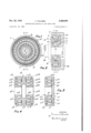
- Fig. 1 represents a transverse section through a bearing incorpo-rating my improvements, the plane of section being indicated 4by the line I-I ⁇ of Fig. 2.
- Fig. 2 is a section on the line 2-2 of Fig. 1, the present View including a fragment of a support for the non-rotating member of the bearing, and' a portion of a shaft that is sustainedbytheY rotating member thereof
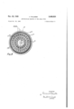
- Fig. 3 is a sectional-view showing a modification of the invention
- Fig.v 4Y is asimilar view of a double bearing. embodying the same modifiedform of the invention as that shown in Fig. 3'
- Fig. 5 is a section on the line 5-5' of.' Fig. 4.
- kMy improved angle ⁇ bearing in the form illustrated in Figs. 1 and 2, comprisesfmembers designated, generally, by the reference numerals I and 2, the former, according to the installation illustrated in Fig. 2, being the non-rotatingmexnber since it is tted'into ⁇ a recess of a stationary support A, which may be the frame or housing of a machine, while the latter, in the present example, is the rotating member and supports a shaft B.
- the member I comprises a peripheral wall 3, shown as cylindrical, an annular flange 4 that is spaced inwardly from andV is concentric with the wall 3, and an annular radial wall 5 that connects-the adjacent ends of the wall 3 and flange 4.
- the member 2 consists of inner and outer cylindrical wallsv 6 and' '1, respectively, that are concentric with the axis of the bearing and are connected together by an annular radial wall d, said'ywalls- 6 to 8 defining a channel in the member 2 into which extends the-flange l of the member I.
- the outer sidev ofl the wall' 6 and the opposed surface of the flange 4' are frusto conical and are disposed at a slight angle with respect to each I other, the projected sides of which angle intersect Onthe axisofv the bearing, as in conventional tapered bea-rings.
- Interposed between the wall 6f and* flange 4- are* a rowof correspondingly tapered rollers 9.
- Surrounding the flange i and capable of sliding thereon is a ring Ill between which and the wall 1 of' the member 2 is a row of rotating bearing elements or balls II, the opposed surfaces of said ring and flange being grooved to provide races for said elements or balls.
- Interposed between the outer side of the wall l and the inner side of the wall 3 is a row oi rotating bearing elements or rollers
- rollersl 9-- which are taperedv to eliminate friction, as understood byV thoseskilled in the artsaid.
- rollers sustain ⁇ end thrust, as well as a good percentage of the radial load, the latter load loe-- ing. taken. also by the rotating bearing elements I4. and
- the elements l2 consist of cylindrical rollers, and the ring It is slidable on the flange 4 and will therefore follow any Inovement in an axial direction of the elements or balls II, the members I and 2 may be adjusted axially toward each other to take up any wear by the inclination of the outer surface of the flange @a to render it suitable for cooperation with the outer row of tapered rollers Ila.
- Fig. 4 illustrates a double bearing which, in
- the distribution of the load in the double or cages may be employed in accordance with ⁇ common practice for maintaining the rotating bearing elements of the respective rows, whether they be balls or rollers, properly spaced circumferentially of the bearing.
- An anti-friction bearing comprising a member consisting of a radial wall having a central opening, an annular flange extending in an axial direction from each side of said Wall and being concentric with the axis of the bearing, opposed bearing members each having a side opening channel into which one of said flanges of the first mentioned member extends, a row of rotating bearing elements between each side of each fiange and the opposed wall of the coresponding channel, the peripheral surfaces of the second mentioned members constituting races, the first mentioned member having parts overlying said peripheral surfaces of the second mentioned members and providing races in opposed relation to those first mentioned, and rows of rotating bearing elements operating between said races.
- An anti-friction bearing comprising a member consisting of a radial wall having a central opening, an annular flange extending in an axial direction from each side of said wall and being concentric with the axis of the bearing, opposed bearing members each having a side opening channel into which one of said flanges of the first mentioned member extends, and a row of rotating bearing elements between each side of each flange and the opposed wall of the corresponding channel, the bearing elements of at least one row consisting of tapered rollers, and the surfaces of the bearing members wherewith they cooperate being correspondingly shaped, the peripheral surfaces of the second mentioned members constituting races, the first mentioned member having parts overlying said peripheral surfaces of the second mentioned members and providing races in opposed relation to those first mentioned, and rows of rotating bearing elements operating between said races.
- An anti-friction bearing comprising a member consisting of a radial wall having a central opening, an annular flange extending in an axial direction from said wall and being concentric with the axis of the bearing, a Second member having a side opening channel into which said flange extends, a row of rotating bearing elements between each side of said flange and the opposed wall of the channel, the peripheral surface of the second member constituting a race, the rst mentioned member having a part overlying said peripheral surface of the second member and providing a race in opposed relation to the first mentioned race, and a row of rotating bearing elements operating between said races,
Landscapes
- Engineering & Computer Science (AREA)
- General Engineering & Computer Science (AREA)
- Mechanical Engineering (AREA)
- Rolling Contact Bearings (AREA)
Description
9109.22, 1949 V', PALUMBO 2,488,929
ANTIFRICTION BEARING OF THE ANGLE TYPE ATTYJ.
Nov., 22, 1949 v. PALUMBO 2,488,929
` ANTIFRICTION BEARING OF' THE ANGLE TYPE Filed Oct. 22, 1945 2 Sheets-Sheet 2 IN V EN TOR.
uw @AWM ATTE/J.
Patented Nov. 22, 1949 UNITEDV STATES PATENT oFFice VincentPalumbo,Cleveland Heights, Ohio Application Octoberl22, 1945, Serial No. 623,624
3 Claims.. (Cl. 308-483) My invention relates to improvements in antifriction bearings of the angle type or class-that is to say, of the kind or class in which both radial load and end thrust are sustained by the same rotating bearing elements. A simple example is a ballbearing having a conical race.
This application is a companion toV oneV titled Anti-friction bearing of the radial type, led October 22, 1945, Serial No. 623,625. While the bearings that form the subject matter of' the two applications are different in type-onebeing radial and the other'angle-they embody a common principle in that* the loadin each case is distributed substantially throughout the entire circumference of the bearing.
The main objectl of the'present invention is to provide an anti-friction bearing'of the angle type or class incorporating this principle.
Other and more general objects are to provide a construction thatl makes manufacture of its parts by prevailing methods easy and inexpensive; that facilitates assembly, andv that increases thev life and eiciency of bearings of the class aforesaid.
The foregoing objects and advantages, with others that arek self evident from the following description, are attained in the embodiments of the invention illustrated in the accompanying drawings, wherein likel reference characters designate corresponding parts throughout the several views.
In the drawings, Fig. 1 represents a transverse section through a bearing incorpo-rating my improvements, the plane of section being indicated 4by the line I-I` of Fig. 2.; Fig. 2 is a section on the line 2-2 of Fig. 1, the present View including a fragment of a support for the non-rotating member of the bearing, and' a portion of a shaft that is sustainedbytheY rotating member thereof; Fig. 3 is a sectional-view showing a modification of the invention; Fig.v 4Y is asimilar view of a double bearing. embodying the same modifiedform of the invention as that shown in Fig. 3'; Fig. 5 is a section on the line 5-5' of.' Fig. 4.
kMy improved angle` bearing, in the form illustrated in Figs. 1 and 2, comprisesfmembers designated, generally, by the reference numerals I and 2, the former, according to the installation illustrated in Fig. 2, being the non-rotatingmexnber since it is tted'into` a recess of a stationary support A, which may be the frame or housing of a machine, while the latter, in the present example, is the rotating member and supports a shaft B. The member I comprises a peripheral wall 3, shown as cylindrical, an annular flange 4 that is spaced inwardly from andV is concentric with the wall 3, and an annular radial wall 5 that connects-the adjacent ends of the wall 3 and flange 4. The member 2 consists of inner and outer cylindrical wallsv 6 and' '1, respectively, that are concentric with the axis of the bearing and are connected together by an annular radial wall d, said'ywalls- 6 to 8 defining a channel in the member 2 into which extends the-flange l of the member I.
The outer sidev ofl the wall' 6 and the opposed surface of the flange 4' are frusto conical and are disposed at a slight angle with respect to each I other, the projected sides of which angle intersect Onthe axisofv the bearing, as in conventional tapered bea-rings. Interposed between the wall 6f and* flange 4- are* a rowof correspondingly tapered rollers 9. Surrounding the flange i and capable of sliding thereon is a ring Ill between which and the wall 1 of' the member 2 is a row of rotating bearing elements or balls II, the opposed surfaces of said ring and flange being grooved to provide races for said elements or balls. Interposed between the outer side of the wall l and the inner side of the wall 3 is a row oi rotating bearing elements or rollers |12.
It is evident from the constructionV above described; that theV load, consistingk in most part of the. weight of the' shaft B, bears, in part, on those rollers S'th'at are beneath the lower half of the wall' 6, and, through saidv rollers, on the underlying parti ofA the flange 4. A further substantial partl of the load, communicated thereto through the. walls 8 and l ofthe member Z, bears on the elements or balls Ill that.V are beneath the upper halfl of the wall 'I and, through them and the ring, I IJ`, on the remainingA part of the flange t. Inother words, the portion of the load so far considered is distributed substantially throughout4 the circumference of said ange 4. The remainder of the load is imposed on the rollers I2 thatlare distributed about; the lower half of the bearing..
By reason of the angular disposition of the rollersl 9--which are taperedv to eliminate friction, as understood byV thoseskilled in the artsaid. rollers sustain` end thrust, as well as a good percentage of the radial load, the latter load loe-- ing. taken. also by the rotating bearing elements I4. and |12'. Because the elements l2 consist of cylindrical rollers, and the ring It is slidable on the flange 4 and will therefore follow any Inovement in an axial direction of the elements or balls II, the members I and 2 may be adjusted axially toward each other to take up any wear by the inclination of the outer surface of the flange @a to render it suitable for cooperation with the outer row of tapered rollers Ila. The taper of these rollers also necessitates a similar change of the inner surface of the outer wall 'la of the bearing member 2a wherewith said rollers engage. The remaining parts of the member 2a, to wit, the annular radial wall 8a and the inner cylindrical wall 5a, are the same as in the rst described form, and a row of tapered rollers 9a operate between the opposed surfaces of the wall 6a and the flange 4a. Traversing the races constituted of the inner surface of the wall 3a and the outer surface of the wall 'la are cylindrical rollers I2a which are capable of moving laterally of said races upon axial adjustment of the members la and 2EL to compensate for wear of the rollers 9a and Ila and the surfaces of said members wherewith they engage.
Fig. 4 illustrates a double bearing which, in
other respects, is identical with the construction Y just described. The parts of the bearing member Ib are duplicated on both sides of a central annular body 5b, and the reference characters applying to said parts on one side of said body include a single exponent, while those applied to the parts on the other side are characterized by a double exponent. This same system is employed in connection with the duplicated bearing members 2b and 2bb.
The distribution of the load in the double or cages may be employed in accordance with` common practice for maintaining the rotating bearing elements of the respective rows, whether they be balls or rollers, properly spaced circumferentially of the bearing.
Having thus described my invention, what -I claim is:
l. An anti-friction bearing comprising a member consisting of a radial wall having a central opening, an annular flange extending in an axial direction from each side of said Wall and being concentric with the axis of the bearing, opposed bearing members each having a side opening channel into which one of said flanges of the first mentioned member extends, a row of rotating bearing elements between each side of each fiange and the opposed wall of the coresponding channel, the peripheral surfaces of the second mentioned members constituting races, the first mentioned member having parts overlying said peripheral surfaces of the second mentioned members and providing races in opposed relation to those first mentioned, and rows of rotating bearing elements operating between said races.
2. An anti-friction bearing comprising a member consisting of a radial wall having a central opening, an annular flange extending in an axial direction from each side of said wall and being concentric with the axis of the bearing, opposed bearing members each having a side opening channel into which one of said flanges of the first mentioned member extends, and a row of rotating bearing elements between each side of each flange and the opposed wall of the corresponding channel, the bearing elements of at least one row consisting of tapered rollers, and the surfaces of the bearing members wherewith they cooperate being correspondingly shaped, the peripheral surfaces of the second mentioned members constituting races, the first mentioned member having parts overlying said peripheral surfaces of the second mentioned members and providing races in opposed relation to those first mentioned, and rows of rotating bearing elements operating between said races.
3. An anti-friction bearing comprising a member consisting of a radial wall having a central opening, an annular flange extending in an axial direction from said wall and being concentric with the axis of the bearing, a Second member having a side opening channel into which said flange extends, a row of rotating bearing elements between each side of said flange and the opposed wall of the channel, the peripheral surface of the second member constituting a race, the rst mentioned member having a part overlying said peripheral surface of the second member and providing a race in opposed relation to the first mentioned race, and a row of rotating bearing elements operating between said races,
-some of the aforesaid bearing elements and the surfaces wherewith they cooperate being shaped to produce an angle bearing.
VINCENT PALUMBO.
REFERENCES CITED The following references are of record in the le of this patent:
UNITED STATES PATENTS Number Name Date 293,619 Bishop Feb. 19, 1884 434,480 Simonds Aug. 19, 1890 633,053 St. Louis Sept. 12, 1899 945,806 Rhodes Jan. 11, 1910 1,008,643 Hess Nov. 14, 1911 1,181,407 Ringland May 2, 1916 1,800,564 OConnor Apr. 14, 1931 V1,804,600 Edson May 12, 1931 1,971,782 Herrmann Aug. 28, 1934 FOREIGN PATENTS Number Country Date 210,527 Germany June 1, 1909
Priority Applications (1)
| Application Number | Priority Date | Filing Date | Title |
|---|---|---|---|
| US623624A US2488929A (en) | 1945-10-22 | 1945-10-22 | Antifriction bearing of the angle type |
Applications Claiming Priority (1)
| Application Number | Priority Date | Filing Date | Title |
|---|---|---|---|
| US623624A US2488929A (en) | 1945-10-22 | 1945-10-22 | Antifriction bearing of the angle type |
Publications (1)
| Publication Number | Publication Date |
|---|---|
| US2488929A true US2488929A (en) | 1949-11-22 |
Family
ID=24498794
Family Applications (1)
| Application Number | Title | Priority Date | Filing Date |
|---|---|---|---|
| US623624A Expired - Lifetime US2488929A (en) | 1945-10-22 | 1945-10-22 | Antifriction bearing of the angle type |
Country Status (1)
| Country | Link |
|---|---|
| US (1) | US2488929A (en) |
Cited By (12)
| Publication number | Priority date | Publication date | Assignee | Title |
|---|---|---|---|---|
| US4618271A (en) * | 1985-12-11 | 1986-10-21 | Florida State University | Serial bearing assembly |
| DE4112253A1 (en) * | 1991-04-15 | 1992-10-22 | Skf Gmbh | Bearing with concentric inner and outer bearing rows - has outer row and inner row, outer races supported on elements, flexible in direction of smallest operating load |
| US20060201076A1 (en) * | 2005-03-11 | 2006-09-14 | The Will-Burt Company | Support bearing assembly |
| WO2010037373A1 (en) * | 2008-09-30 | 2010-04-08 | Schaeffler Kg | Rotor bearing for a wind turbine, comprising a double, multi-row rolling bearing with three concentric bearing rings |
| WO2010037370A1 (en) * | 2008-09-30 | 2010-04-08 | Schaeffler Kg | Rotational connection, in particular rolling bearing comprising three concentric bearing rings and rolling body rows with intersecting bearing lines, or four-point contact ball bearings, for a wind turbine |
| US20150038279A1 (en) * | 2013-07-31 | 2015-02-05 | American Axle & Manufacturing, Inc. | Bearing assembly configured to handle axial and radial loads |
| WO2015057138A1 (en) * | 2013-10-17 | 2015-04-23 | Aktiebolaget Skf | Bearing arrangement |
| WO2015057126A1 (en) * | 2013-10-17 | 2015-04-23 | Aktiebolaget Skf | Wind turbine rotor bearing arrangement |
| DE102014106558A1 (en) * | 2014-05-09 | 2015-11-12 | Thyssenkrupp Ag | Bearing arrangement and tapered roller bearings |
| US20160238070A1 (en) * | 2013-10-17 | 2016-08-18 | Aktiebolaget Skf | Bearing for combined loads |
| CN114483769A (en) * | 2022-01-25 | 2022-05-13 | 中国铁建重工集团股份有限公司 | Novel aligning slewing bearing with high unbalance loading bearing capacity |
| US20220170507A1 (en) * | 2019-03-15 | 2022-06-02 | Minebea Mitsumi Inc. | Motor, motor state detection device, and motor state determination device |
Citations (10)
| Publication number | Priority date | Publication date | Assignee | Title |
|---|---|---|---|---|
| US293619A (en) * | 1884-02-19 | bishop | ||
| US434480A (en) * | 1890-08-19 | Ball-bearing | ||
| US633053A (en) * | 1899-06-06 | 1899-09-12 | Philip M St Louis | Roller-bearing. |
| DE210527C (en) * | 1900-01-01 | |||
| US945806A (en) * | 1907-02-18 | 1910-01-11 | Austin Mfg Company | Gyratory crusher. |
| US1008643A (en) * | 1909-02-13 | 1911-11-14 | Hess Bright Mfg Co | Antifriction-bearing. |
| US1181407A (en) * | 1912-06-27 | 1916-05-02 | Standard Roller Bearing Company | Annular bearing. |
| US1800564A (en) * | 1927-11-02 | 1931-04-14 | Miner Inc W H | Journal bearing |
| US1804600A (en) * | 1928-07-12 | 1931-05-12 | Edson Elmer Rockwood | Guard wheel for safety railway trucks |
| US1971782A (en) * | 1933-09-30 | 1934-08-28 | Karl L Herrmann | Roller bearing |
-
1945
- 1945-10-22 US US623624A patent/US2488929A/en not_active Expired - Lifetime
Patent Citations (10)
| Publication number | Priority date | Publication date | Assignee | Title |
|---|---|---|---|---|
| US293619A (en) * | 1884-02-19 | bishop | ||
| US434480A (en) * | 1890-08-19 | Ball-bearing | ||
| DE210527C (en) * | 1900-01-01 | |||
| US633053A (en) * | 1899-06-06 | 1899-09-12 | Philip M St Louis | Roller-bearing. |
| US945806A (en) * | 1907-02-18 | 1910-01-11 | Austin Mfg Company | Gyratory crusher. |
| US1008643A (en) * | 1909-02-13 | 1911-11-14 | Hess Bright Mfg Co | Antifriction-bearing. |
| US1181407A (en) * | 1912-06-27 | 1916-05-02 | Standard Roller Bearing Company | Annular bearing. |
| US1800564A (en) * | 1927-11-02 | 1931-04-14 | Miner Inc W H | Journal bearing |
| US1804600A (en) * | 1928-07-12 | 1931-05-12 | Edson Elmer Rockwood | Guard wheel for safety railway trucks |
| US1971782A (en) * | 1933-09-30 | 1934-08-28 | Karl L Herrmann | Roller bearing |
Cited By (24)
| Publication number | Priority date | Publication date | Assignee | Title |
|---|---|---|---|---|
| US4618271A (en) * | 1985-12-11 | 1986-10-21 | Florida State University | Serial bearing assembly |
| DE4112253A1 (en) * | 1991-04-15 | 1992-10-22 | Skf Gmbh | Bearing with concentric inner and outer bearing rows - has outer row and inner row, outer races supported on elements, flexible in direction of smallest operating load |
| EP1856351A4 (en) * | 2005-03-11 | 2011-03-02 | Burt Will Comp | Support bearing assembly |
| US20060201076A1 (en) * | 2005-03-11 | 2006-09-14 | The Will-Burt Company | Support bearing assembly |
| WO2006098775A2 (en) | 2005-03-11 | 2006-09-21 | The Will-Burt Company | Support bearing assembly |
| EP1856351A2 (en) * | 2005-03-11 | 2007-11-21 | The Will-Burt Company | Support bearing assembly |
| US8887450B2 (en) | 2005-03-11 | 2014-11-18 | The Will-Burt Company | Support bearing assembly |
| WO2010037370A1 (en) * | 2008-09-30 | 2010-04-08 | Schaeffler Kg | Rotational connection, in particular rolling bearing comprising three concentric bearing rings and rolling body rows with intersecting bearing lines, or four-point contact ball bearings, for a wind turbine |
| WO2010037373A1 (en) * | 2008-09-30 | 2010-04-08 | Schaeffler Kg | Rotor bearing for a wind turbine, comprising a double, multi-row rolling bearing with three concentric bearing rings |
| CN105358847A (en) * | 2013-07-31 | 2016-02-24 | 美国轮轴制造公司 | Bearing assembly configured to handle axial and radial loads |
| US20150038279A1 (en) * | 2013-07-31 | 2015-02-05 | American Axle & Manufacturing, Inc. | Bearing assembly configured to handle axial and radial loads |
| DE112014003547B4 (en) | 2013-07-31 | 2022-02-17 | American Axle & Manufacturing, Inc. | Bearing assembly configured to handle axial and radial loads |
| US9593756B2 (en) * | 2013-07-31 | 2017-03-14 | American Axle & Manufacturing, Inc. | Bearing assembly configured to handle axial and radial loads |
| US9822814B2 (en) * | 2013-10-17 | 2017-11-21 | Aktiebolaget Skf | Bearing for combined loads |
| CN105658971A (en) * | 2013-10-17 | 2016-06-08 | 斯凯孚公司 | Bearing arrangement |
| US20160238070A1 (en) * | 2013-10-17 | 2016-08-18 | Aktiebolaget Skf | Bearing for combined loads |
| US20160258482A1 (en) * | 2013-10-17 | 2016-09-08 | Aktiebolaget Skf | Bearing arrangement |
| WO2015057126A1 (en) * | 2013-10-17 | 2015-04-23 | Aktiebolaget Skf | Wind turbine rotor bearing arrangement |
| US10197093B2 (en) | 2013-10-17 | 2019-02-05 | Aktiebolaget Skf | Bearing arrangement |
| CN105658971B (en) * | 2013-10-17 | 2019-05-03 | 斯凯孚公司 | Bearing arrangement |
| WO2015057138A1 (en) * | 2013-10-17 | 2015-04-23 | Aktiebolaget Skf | Bearing arrangement |
| DE102014106558A1 (en) * | 2014-05-09 | 2015-11-12 | Thyssenkrupp Ag | Bearing arrangement and tapered roller bearings |
| US20220170507A1 (en) * | 2019-03-15 | 2022-06-02 | Minebea Mitsumi Inc. | Motor, motor state detection device, and motor state determination device |
| CN114483769A (en) * | 2022-01-25 | 2022-05-13 | 中国铁建重工集团股份有限公司 | Novel aligning slewing bearing with high unbalance loading bearing capacity |
Similar Documents
| Publication | Publication Date | Title |
|---|---|---|
| US2488929A (en) | Antifriction bearing of the angle type | |
| US3652141A (en) | Combined three-sectional axial-radial roller turning connection | |
| US2488825A (en) | Antifriction bearing | |
| US3361501A (en) | Rolling bearings | |
| US3166363A (en) | Split roller bearings | |
| US2195795A (en) | Roller bearing | |
| US3361500A (en) | Antifriction bearing | |
| US2387962A (en) | Antifriction bearing | |
| US3552812A (en) | Angular-contact bearing construction | |
| US3161448A (en) | Outer ring for antifriction bearing | |
| US1645345A (en) | Ball bearing | |
| US3556618A (en) | Double race screwdown thrust bearing | |
| US1965293A (en) | Bearing | |
| US20210102576A1 (en) | Self-aligning roller bearing | |
| US3128134A (en) | Triple race tapered roller bearings | |
| US3829183A (en) | Ultra high speed rolling bearing assembly | |
| US3022125A (en) | Cage for double row spherical roller bearings | |
| US3268278A (en) | Rolling bearings | |
| US2884288A (en) | Needle roller bearings | |
| US4209210A (en) | Self-aligning two row thrust roller bearing | |
| US1789007A (en) | Self-adjusting roller bearing | |
| US1649285A (en) | Bearing | |
| US3206263A (en) | Cage for antifriction bearings | |
| US2983559A (en) | Antifriction bearing | |
| US2128668A (en) | Double row roller bearing |