WO2020189357A1 - 原料流体の処理プラント、及び原料流体の処理方法 - Google Patents
原料流体の処理プラント、及び原料流体の処理方法 Download PDFInfo
- Publication number
- WO2020189357A1 WO2020189357A1 PCT/JP2020/009904 JP2020009904W WO2020189357A1 WO 2020189357 A1 WO2020189357 A1 WO 2020189357A1 JP 2020009904 W JP2020009904 W JP 2020009904W WO 2020189357 A1 WO2020189357 A1 WO 2020189357A1
- Authority
- WO
- WIPO (PCT)
- Prior art keywords
- heat
- raw material
- medium
- heat medium
- gas
- Prior art date
- Legal status (The legal status is an assumption and is not a legal conclusion. Google has not performed a legal analysis and makes no representation as to the accuracy of the status listed.)
- Ceased
Links
Images


Classifications
-
- B—PERFORMING OPERATIONS; TRANSPORTING
- B01—PHYSICAL OR CHEMICAL PROCESSES OR APPARATUS IN GENERAL
- B01J—CHEMICAL OR PHYSICAL PROCESSES, e.g. CATALYSIS OR COLLOID CHEMISTRY; THEIR RELEVANT APPARATUS
- B01J19/00—Chemical, physical or physico-chemical processes in general; Their relevant apparatus
- B01J19/0006—Controlling or regulating processes
- B01J19/0013—Controlling the temperature of the process
-
- B—PERFORMING OPERATIONS; TRANSPORTING
- B01—PHYSICAL OR CHEMICAL PROCESSES OR APPARATUS IN GENERAL
- B01J—CHEMICAL OR PHYSICAL PROCESSES, e.g. CATALYSIS OR COLLOID CHEMISTRY; THEIR RELEVANT APPARATUS
- B01J19/00—Chemical, physical or physico-chemical processes in general; Their relevant apparatus
- B01J19/32—Packing elements in the form of grids or built-up elements for forming a unit or module inside the apparatus for mass or heat transfer
-
- F—MECHANICAL ENGINEERING; LIGHTING; HEATING; WEAPONS; BLASTING
- F02—COMBUSTION ENGINES; HOT-GAS OR COMBUSTION-PRODUCT ENGINE PLANTS
- F02C—GAS-TURBINE PLANTS; AIR INTAKES FOR JET-PROPULSION PLANTS; CONTROLLING FUEL SUPPLY IN AIR-BREATHING JET-PROPULSION PLANTS
- F02C6/00—Plural gas-turbine plants; Combinations of gas-turbine plants with other apparatus; Adaptations of gas-turbine plants for special use
- F02C6/18—Plural gas-turbine plants; Combinations of gas-turbine plants with other apparatus; Adaptations of gas-turbine plants for special use using the waste heat of gas-turbine plants outside the plants themselves, e.g. gas-turbine power heat plants
-
- B—PERFORMING OPERATIONS; TRANSPORTING
- B01—PHYSICAL OR CHEMICAL PROCESSES OR APPARATUS IN GENERAL
- B01J—CHEMICAL OR PHYSICAL PROCESSES, e.g. CATALYSIS OR COLLOID CHEMISTRY; THEIR RELEVANT APPARATUS
- B01J19/00—Chemical, physical or physico-chemical processes in general; Their relevant apparatus
- B01J19/0053—Details of the reactor
-
- C—CHEMISTRY; METALLURGY
- C01—INORGANIC CHEMISTRY
- C01B—NON-METALLIC ELEMENTS; COMPOUNDS THEREOF; METALLOIDS OR COMPOUNDS THEREOF NOT COVERED BY SUBCLASS C01C
- C01B3/00—Hydrogen; Gaseous mixtures containing hydrogen; Separation of hydrogen from mixtures containing it; Purification of hydrogen; Reversible storage of hydrogen
- C01B3/02—Production of hydrogen; Production of gaseous mixtures containing hydrogen
- C01B3/04—Production of hydrogen; Production of gaseous mixtures containing hydrogen by decomposition of inorganic compounds
-
- F—MECHANICAL ENGINEERING; LIGHTING; HEATING; WEAPONS; BLASTING
- F01—MACHINES OR ENGINES IN GENERAL; ENGINE PLANTS IN GENERAL; STEAM ENGINES
- F01K—STEAM ENGINE PLANTS; STEAM ACCUMULATORS; ENGINE PLANTS NOT OTHERWISE PROVIDED FOR; ENGINES USING SPECIAL WORKING FLUIDS OR CYCLES
- F01K23/00—Plants characterised by more than one engine delivering power external to the plant, the engines being driven by different fluids
- F01K23/02—Plants characterised by more than one engine delivering power external to the plant, the engines being driven by different fluids the engine cycles being thermally coupled
- F01K23/06—Plants characterised by more than one engine delivering power external to the plant, the engines being driven by different fluids the engine cycles being thermally coupled combustion heat from one cycle heating the fluid in another cycle
- F01K23/10—Plants characterised by more than one engine delivering power external to the plant, the engines being driven by different fluids the engine cycles being thermally coupled combustion heat from one cycle heating the fluid in another cycle with exhaust fluid of one cycle heating the fluid in another cycle
-
- F—MECHANICAL ENGINEERING; LIGHTING; HEATING; WEAPONS; BLASTING
- F01—MACHINES OR ENGINES IN GENERAL; ENGINE PLANTS IN GENERAL; STEAM ENGINES
- F01K—STEAM ENGINE PLANTS; STEAM ACCUMULATORS; ENGINE PLANTS NOT OTHERWISE PROVIDED FOR; ENGINES USING SPECIAL WORKING FLUIDS OR CYCLES
- F01K25/00—Plants or engines characterised by use of special working fluids, not otherwise provided for; Plants operating in closed cycles and not otherwise provided for
- F01K25/08—Plants or engines characterised by use of special working fluids, not otherwise provided for; Plants operating in closed cycles and not otherwise provided for using special vapours
- F01K25/10—Plants or engines characterised by use of special working fluids, not otherwise provided for; Plants operating in closed cycles and not otherwise provided for using special vapours the vapours being cold, e.g. ammonia, carbon dioxide, ether
- F01K25/103—Carbon dioxide
-
- F—MECHANICAL ENGINEERING; LIGHTING; HEATING; WEAPONS; BLASTING
- F01—MACHINES OR ENGINES IN GENERAL; ENGINE PLANTS IN GENERAL; STEAM ENGINES
- F01K—STEAM ENGINE PLANTS; STEAM ACCUMULATORS; ENGINE PLANTS NOT OTHERWISE PROVIDED FOR; ENGINES USING SPECIAL WORKING FLUIDS OR CYCLES
- F01K7/00—Steam engine plants characterised by the use of specific types of engine; Plants or engines characterised by their use of special steam systems, cycles or processes; Control means specially adapted for such systems, cycles or processes; Use of withdrawn or exhaust steam for feed-water heating
- F01K7/16—Steam engine plants characterised by the use of specific types of engine; Plants or engines characterised by their use of special steam systems, cycles or processes; Control means specially adapted for such systems, cycles or processes; Use of withdrawn or exhaust steam for feed-water heating the engines being only of turbine type
- F01K7/18—Steam engine plants characterised by the use of specific types of engine; Plants or engines characterised by their use of special steam systems, cycles or processes; Control means specially adapted for such systems, cycles or processes; Use of withdrawn or exhaust steam for feed-water heating the engines being only of turbine type the turbine being of multiple-inlet-pressure type
-
- F—MECHANICAL ENGINEERING; LIGHTING; HEATING; WEAPONS; BLASTING
- F02—COMBUSTION ENGINES; HOT-GAS OR COMBUSTION-PRODUCT ENGINE PLANTS
- F02C—GAS-TURBINE PLANTS; AIR INTAKES FOR JET-PROPULSION PLANTS; CONTROLLING FUEL SUPPLY IN AIR-BREATHING JET-PROPULSION PLANTS
- F02C6/00—Plural gas-turbine plants; Combinations of gas-turbine plants with other apparatus; Adaptations of gas-turbine plants for special use
-
- B—PERFORMING OPERATIONS; TRANSPORTING
- B01—PHYSICAL OR CHEMICAL PROCESSES OR APPARATUS IN GENERAL
- B01J—CHEMICAL OR PHYSICAL PROCESSES, e.g. CATALYSIS OR COLLOID CHEMISTRY; THEIR RELEVANT APPARATUS
- B01J2219/00—Chemical, physical or physico-chemical processes in general; Their relevant apparatus
- B01J2219/00049—Controlling or regulating processes
- B01J2219/00051—Controlling the temperature
- B01J2219/00159—Controlling the temperature controlling multiple zones along the direction of flow, e.g. pre-heating and after-cooling
-
- Y—GENERAL TAGGING OF NEW TECHNOLOGICAL DEVELOPMENTS; GENERAL TAGGING OF CROSS-SECTIONAL TECHNOLOGIES SPANNING OVER SEVERAL SECTIONS OF THE IPC; TECHNICAL SUBJECTS COVERED BY FORMER USPC CROSS-REFERENCE ART COLLECTIONS [XRACs] AND DIGESTS
- Y02—TECHNOLOGIES OR APPLICATIONS FOR MITIGATION OR ADAPTATION AGAINST CLIMATE CHANGE
- Y02E—REDUCTION OF GREENHOUSE GAS [GHG] EMISSIONS, RELATED TO ENERGY GENERATION, TRANSMISSION OR DISTRIBUTION
- Y02E20/00—Combustion technologies with mitigation potential
- Y02E20/16—Combined cycle power plant [CCPP], or combined cycle gas turbine [CCGT]
-
- Y—GENERAL TAGGING OF NEW TECHNOLOGICAL DEVELOPMENTS; GENERAL TAGGING OF CROSS-SECTIONAL TECHNOLOGIES SPANNING OVER SEVERAL SECTIONS OF THE IPC; TECHNICAL SUBJECTS COVERED BY FORMER USPC CROSS-REFERENCE ART COLLECTIONS [XRACs] AND DIGESTS
- Y02—TECHNOLOGIES OR APPLICATIONS FOR MITIGATION OR ADAPTATION AGAINST CLIMATE CHANGE
- Y02E—REDUCTION OF GREENHOUSE GAS [GHG] EMISSIONS, RELATED TO ENERGY GENERATION, TRANSMISSION OR DISTRIBUTION
- Y02E60/00—Enabling technologies; Technologies with a potential or indirect contribution to GHG emissions mitigation
- Y02E60/30—Hydrogen technology
- Y02E60/36—Hydrogen production from non-carbon containing sources, e.g. by water electrolysis
Definitions
- the present invention relates to a technique including a process of heating and reacting a raw material fluid to generate a reaction gas.
- the present application claims priority based on Japanese Patent Application No. 2019-048890 filed in Japan on March 15, 2019, and this content is incorporated herein by reference.
- Patent Documents 1 and 2 disclose gas turbine plants.
- This gas turbine plant is equipped with a raw material reaction facility that heats ammonia and thermally decomposes the ammonia into hydrogen and nitrogen.
- the raw material reaction facility has one heat exchange device.
- This single heat exchange device has a gas frame through which the exhaust gas from the gas bin flows, and a heat transfer tube arranged in the gas frame.
- the liquid ammonia flowing into the heat transfer tube and the exhaust gas flowing in the gas frame are heat-exchanged to heat the ammonia, and the ammonia is thermally decomposed to cause hydrogen.
- the reaction gas contains and nitrogen. This reaction gas is guided to the combustor of the gas turbine.
- a single heat exchange device exchanges heat between liquid ammonia and exhaust gas to heat the ammonia and cause the ammonia to undergo a thermal decomposition reaction.
- the thermal energy loss of the gas increases.
- the heat of the reaction gas after the reaction is not effectively utilized. Therefore, in the techniques described in Patent Documents 1 and 2, the thermal efficiency of the plant is lowered.
- an object of the present invention is to provide a technique capable of suppressing the thermal energy loss of a heat source such as exhaust gas and improving the thermal efficiency of a plant when reacting a raw material fluid such as ammonia.
- One aspect of the raw material fluid processing plant according to the invention for achieving the above object is It is equipped with a raw material reaction facility that heats and reacts the raw material fluid to generate a reaction gas.
- a raw material reaction facility that heats and reacts the raw material fluid to generate a reaction gas.
- a preheater for preheating the raw material fluid
- a reactor for further heating and reacting the raw material fluid preheated by the preheater to generate a reaction gas
- a first heat medium flow through the first heat medium. It has one heat medium line and a second heat medium line through which a second heat medium different from the first heat medium flows.
- the reactor is a heat exchanger in which the raw material fluid and the first heat medium are heat-exchanged to heat and react the raw material fluid.
- the preheater is a heat exchanger that heats the raw material fluid by exchanging heat between the raw material fluid and the second heat medium.
- the first heat medium line guides the first heat medium to the reactor.
- the second heat medium line guides the second heat medium to the preheater.
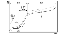
- the raw material fluid when the raw material fluid is heated and reacted, first, the raw material fluid is preheated by heat exchange between the second heat medium different from the first heat medium and the raw material fluid. Then, in this embodiment, the first heat medium and the preheated raw material fluid are heat-exchanged to heat and react the raw material fluid. Therefore, in this embodiment, the amount of heat for heating the first heat medium can be reduced as compared with the case where the raw material fluid is preheated and reacted with one heat medium. Therefore, in this embodiment, it is possible to suppress the heat energy loss of the heat source such as the exhaust gas for heating the first heat medium.
- the product of the constant pressure specific heat of the first heat medium flowing through the first heat medium line and the flow rate is the product of the constant pressure specific heat and the flow rate of the second heat medium flowing through the second heat medium line. It may be larger than the product of the constant pressure specific heat and the flow rate.
- a large amount of heat can be applied to the temperature level of the reactor, which requires a large amount of heat for the reaction of the raw material fluid, and a small amount of heat can be applied to the temperature level of the preheater, which is sufficient with a small amount of heat. Can be done. Therefore, the amount of heat required for each temperature level can be input without excess or deficiency, and heat can be effectively used according to the temperature level.
- the heat cycle medium has a heat cycle utilizing exhaust heat in which the heat cycle medium circulates, and the heat of the heat source is used to heat the heat cycle medium to heat the heat cycle medium.
- exhaust heat utilization equipment using a heat cycle medium may be provided.
- the exhaust heat utilization facility heats the first heat medium by utilizing the heat of the heat source.
- the first heat medium line guides the first heat medium heated by the heat of the heat source to the reactor.
- the portion not used for generating the reaction gas can be utilized in the heat cycle, and the output and efficiency of the plant can be improved.
- the exhaust gas generating equipment for generating exhaust gas may be further provided in the raw material fluid processing plant of the above embodiment provided with the exhaust heat utilization equipment.
- the heat source is the exhaust gas from the exhaust gas generating facility.
- the exhaust heat utilization facility heats the heat cycle medium by exchanging heat with the exhaust gas.
- the exhaust heat utilization facility is provided in a gas frame through which the exhaust gas flows and in the gas frame, and heats the first heat medium by exchanging heat between the first heat medium and the exhaust gas. It has a heat medium heater.
- the first heat medium line is connected to the first heat medium heater of the exhaust heat utilization facility, and the first heat medium heated by the heat of the exhaust gas is guided to the reactor.
- the efficiency of the plant can be improved by effectively utilizing the heat of the exhaust gas from the exhaust gas generating facility.
- the exhaust gas generating equipment may be a reaction gas utilization equipment using the reaction gas as fuel.
- a reaction gas utilization facility different from the exhaust heat utilization facility can be provided, and the exhaust heat after the reaction gas is used in the reaction gas utilization facility can be further utilized in the exhaust heat utilization facility. , The energy of the reaction gas can be recovered repeatedly, and highly efficient energy utilization becomes possible.
- the raw material reaction facility heats the first heat medium after heat exchange with the raw material fluid from the reactor to the first heat medium. It may have a first heat medium recovery line to return to the vessel.
- the first heat medium circulates between the reactor and the first heat medium heater. Therefore, in this embodiment, the temperature difference between the temperature of the first heat medium flowing out of the first heat medium heater and the temperature of the first heat medium flowing into the first heat medium heater can be minimized. Therefore, in this aspect as well, the amount of heat for heating the first heat medium can be reduced from this viewpoint as well.
- the reactor is said to have after heat exchange between the first heat medium and the raw material fluid before heat exchange with the raw material fluid. It may be configured so as not to change the phase with the first heat medium.
- the phase does not change in the process in which the first heat medium circulates between the reactor and the first heat medium heater. Therefore, in this embodiment, the amount of heat for heating the first heat medium can be reduced as compared with the case where the first heat medium undergoes a phase change.
- At least one of the first heat medium and the second heat medium is the same as the heat cycle medium. It may be a substance.
- the quality of the first heat medium or the second heat medium can be easily controlled.
- the pressure of one heat medium is the pressure of the heat cycle medium in the exhaust heat utilization heat cycle. It may be lower than the maximum pressure.
- the first heat medium can be easily supplied to the reactor or the second heat medium can be supplied to the preheater without providing a separate supply facility.
- the first heat medium can be easily supplied to the reactor or the second heat medium can be supplied to the preheater at the time of startup or when the pressure of the first heat medium drops due to seal leakage or the like.
- the reactor includes a pre-reactor that further heats and reacts the raw material fluid preheated by the preheater to generate a reaction gas, and the pre-reactor. It may have a post-reactor in which the gas from the reactor is further heated to react the raw material fluid contained in the gas from the pre-reactor.
- the pre-reactor heats the raw material fluid by exchanging heat between the first low temperature heat medium, which is a kind of the first heat medium, and the raw material fluid.
- the post-reactor is a type of the first heat medium that exchanges heat with a gas from the pre-reactor and a first high-temperature heat medium different from the first low-temperature heat medium, from the pre-reactor. Heat the gas.
- the first heat medium line includes a first low temperature heat medium line through which the first low temperature heat medium flows, and a first high temperature heat medium line through which the first high temperature heat medium flows.
- the first low temperature heat medium line is connected to the pre-reactor and guides the first low temperature heat medium to the pre-reactor.
- the first high temperature heat medium line is connected to the post-reactor and guides the first high temperature heat medium to the post-reactor.
- the reaction of the raw material fluid is executed in two stages of the reaction in the pre-reactor and the reaction in the post-reactor, the residue contained in the reaction gas flowing out from the post-reactor is executed.
- the concentration of the raw material can be reduced.
- the temperature of the first heat medium that exchanges heat with the reaction gas in the post-reactor is higher than the temperature of the first heat medium that exchanges heat with the raw material fluid in the pre-reactor, so that the reaction is performed. Heat can be used efficiently. Further, by dividing the reactor into a pre-reactor and a post-reactor and supplying a heat medium to each, the amount of heat required for each temperature level can be input in just proportion to the temperature level. Heat can be used effectively accordingly.
- the reactor further heats the raw material fluid preheated by the preheater to react. It has a pre-reactor for producing a reaction gas, and a post-reactor for further heating the gas from the pre-reactor to react the raw material fluid contained in the gas from the pre-reactor. May be good.
- the first heat medium heater exchanges heat between the first low temperature heat medium, which is a kind of the first heat medium, and the exhaust gas to heat the first low temperature heat medium.
- the first high-temperature heating medium heater is arranged in the gas frame on the upstream side of the exhaust gas flow with respect to the first low-temperature heating medium heater.
- the first heat medium line includes a first low temperature heat medium line through which the first low temperature heat medium flows, and a first high temperature heat medium line through which the first high temperature heat medium flows.
- the first low temperature heat medium line is connected to the first low temperature heat medium heater and guides the first low temperature heat medium heated by the exhaust gas to the pre-reactor.
- the first high temperature heat medium line is connected to the first high temperature heat medium heater and guides the first high temperature heat medium heated by the exhaust gas to the post-reactor.
- the reaction of the raw material fluid is executed in two stages of the reaction in the pre-reactor and the reaction in the post-reactor, the residue contained in the reaction gas flowing out from the post-reactor is executed.
- the concentration of the raw material can be reduced.
- the temperature of the first heat medium that exchanges heat with the reaction gas in the post-reactor is higher than the temperature of the first heat medium that exchanges heat with the raw material fluid in the pre-reactor, so that the reaction is performed. Heat can be used efficiently. Further, by dividing the reactor into a pre-reactor and a post-reactor and supplying a heat medium to each, the amount of heat required for each temperature level can be input in just proportion to the temperature level. Heat can be used effectively accordingly.
- the waste heat utilization facility has an exhaust heat recovery boiler that uses the heat of the exhaust gas to vaporize water.
- the exhaust heat recovery boiler has the gas frame, and both the first low-temperature heat medium and the first high-temperature heat medium may be water or steam.
- the exhaust heat utilization facility injects fuel into the exhaust gas flowing in the gas frame. It may have a burner for burning the fuel. In this case, the burner is arranged in the gas frame on the upstream side of the flow of the exhaust gas with respect to the first high-temperature heating medium heater.
- the first high-temperature heat medium heater heats the first high-temperature heat medium by exchanging heat between the combustion gas generated by the combustion of the fuel injected from the burner and the first high-temperature heat medium.
- the reaction of the raw material fluid can be promoted, and the raw material contained in the reaction gas can be promoted.
- the concentration of the fluid can be reduced.
- the exhaust heat utilization facility is contained in the exhaust gas flowing in the gas frame. It may have a burner that injects fuel and burns the fuel.
- the burner is arranged in the gas frame on the upstream side of the flow of the exhaust gas with respect to the first heat medium heater.
- the first heat medium heater heats the first heat medium by exchanging heat between the combustion gas generated by the combustion of the fuel injected from the burner and the first heat medium.
- the reaction of the raw material fluid can be promoted, and the raw material contained in the reaction gas can be promoted.
- the concentration of the fluid can be reduced.
- the constant pressure of the first low temperature heat medium flowing through the first low temperature heat medium line may be larger than the product of the constant pressure specific heat of the first high temperature heat medium flowing through the first high temperature heat medium line and the flow rate.
- a large amount of heat can be applied to the temperature level of the reactor, which requires a large amount of heat for the reaction of the raw material fluid, and a small amount of heat can be applied to the temperature level of the preheater, which is sufficient with a small amount of heat.
- the amount of heat required for each temperature level can be input without excess or deficiency, and heat can be effectively used according to the temperature level.
- the required flow rate of the high-temperature first high-temperature heat medium to be charged into the post-reactor can be reduced, high-temperature heat is saved, and heat utilization efficiency is achieved. Can be enhanced.
- the exhaust heat utilization facility is located upstream of the exhaust gas flow in the gas frame with respect to the first heat medium heater.
- the partition member may be provided to partition the first exhaust gas flow path through which a part of the exhaust gas flows and the second exhaust gas flow path through which the remaining part of the exhaust gas flows.
- the burner injects the fuel into the first exhaust gas flow path.
- the temperature of the first heat medium can be effectively raised with a small amount of reheating fuel. Burning fuel can be saved and plant efficiency can be improved.
- the raw material reaction facility includes a reaction gas line through which the reaction gas generated by the reactor flows and the reaction gas line. It may have a residual raw material removing device for removing the residual raw material which is a raw material fluid contained in the reaction gas flowing through the above and discharging the treated reaction gas which is the reaction gas from which the residual raw material has been removed.
- the exhaust gas generating facility utilizes the processed reaction gas which is a part of the reaction gas.
- the amount of residual raw material in the reaction gas sent to the reaction gas utilization facility can be reduced.
- the second heat medium may be the reaction gas
- the second heat medium line may be the reaction gas line
- the preheater exchanges heat between the raw material fluid and the reaction gas as the second heat medium, and while the raw material fluid is heated, the reaction gas is cooled. Therefore, in this embodiment, the low temperature reaction gas can be sent to the residual raw material removing device. Further, the plant efficiency can be improved by effectively utilizing the exhaust heat of the reaction gas cooling.
- the preheater is a vaporizer that heats and vaporizes the liquid raw material fluid and gas heating that heats the gas raw material fluid from the vaporizer.
- the vaporizer is a heat exchanger that heats the liquid raw material fluid by exchanging heat between the vaporization second heat medium, which is a kind of the second heat medium, and the liquid raw material fluid.
- the gas heater is a kind of the second heat medium and is different from the second heat medium for vaporization, and heat exchanges between the second heat medium for gas heating and the raw material fluid of the gas to exchange the heat of the gas.
- a heat exchanger that heats the raw material fluid.
- different heat media are used for vaporization of the raw material fluid that requires a large amount of heat and heating with a gas that requires a small amount of heat.
- the amount of heat required for each temperature level can be input in just proportion to the vaporization of the raw material fluid and the heating with a gas, and the heat is effectively used according to the temperature level. be able to.
- the product of the constant pressure specific heat and the flow rate of the second heat medium for vaporization flowing in the vaporizer flows in the gas heater. It may be larger than the product of the constant pressure specific heat and the flow rate of the second heat medium for gas heating.
- a large amount of heat can be applied to the temperature level of the vaporizer, which requires a large amount of heat for vaporizing the raw material fluid, and a sufficient amount of heat can be applied to the temperature level of the gas heater with a small amount of heat. Can be done. Therefore, the amount of heat required for each temperature level can be input without excess or deficiency, heat can be effectively used according to the temperature level, and heat utilization efficiency can be improved.
- the vaporizer accepts the second heat medium for vaporization of the gas, and the second heat medium for vaporization of the gas and the liquid. It may have the ability to cool and condense the second heat medium for vaporization of the gas by exchanging heat with the raw material fluid of the gas.
- the heat source medium can be vaporized at a constant temperature by using the second heat medium for vaporization that condenses at a constant temperature as a heat source. Therefore, in this embodiment, the heat of a relatively low constant temperature can be effectively utilized to vaporize the raw material fluid, and the heat utilization efficiency can be improved.
- the vaporizer is a liquid phase preheater for raising the temperature of the raw material fluid of the liquid as it is, and a liquid phase preheater. It may have a phase change preheater that heats and vaporizes the liquid raw material fluid.
- the liquid phase preheater heats the liquid raw material fluid by exchanging heat between the liquid phase preheating second heat medium, which is a kind of the vaporization second heat medium, and the liquid raw material fluid. It is a heat exchanger.
- the phase change preheater is a kind of the second heat medium for vaporization and is different from the second heat medium for liquid phase preheating, and the second heat medium for phase change preheating and the raw material of the liquid from the liquid phase preheater. It is a heat exchanger that exchanges heat with a fluid to heat the raw material fluid of the liquid.
- the vaporizer is divided into a portion for vaporizing the raw material fluid in the liquid phase and a portion for preheating the raw material fluid in the liquid phase. Then, different heat media are used for vaporization of the raw material fluid that requires a large amount of heat and for heating with the liquid phase having a small amount of heat required. Therefore, in this embodiment, the amount of heat required for each temperature level can be input in just proportion to the vaporization of the raw material fluid and the heating in the liquid phase, which is effective according to the temperature level. The heat can be utilized.
- the product of the constant pressure specific heat and the flow rate of the second heat medium for phase change preheating flowing in the phase change preheater is It may be larger than the product of the constant pressure specific heat and the flow rate of the second heat medium for liquid phase preheating flowing in the liquid phase preheater.
- a large amount of heat can be applied to the temperature level of the phase change preheater that requires a large amount of heat for vaporization of the raw material fluid, and a small amount of heat can be applied to the temperature level of the liquid phase preheater that is sufficient with a small amount of heat. Can be thrown in. Therefore, the amount of heat required for each temperature level can be input without excess or deficiency, heat can be effectively used according to the temperature level, and heat utilization efficiency can be improved.
- the phase change preheater receives the second heat medium for phase change preheating of the gas and the phase change of the gas. It may have the ability to exchange heat between the second heat medium for preheating and the raw material fluid of the liquid from the liquid phase preheater to cool and condense the second heat medium for phase change preheating of the gas.
- the raw material fluid can be vaporized at a constant temperature using a second heat medium for phase change preheating that condenses at a constant temperature as a heat source. Therefore, in this embodiment, the heat of a relatively low constant temperature can be effectively utilized to vaporize the raw material fluid, and the heat utilization efficiency can be improved.
- the raw material fluid processing plant of any of the above embodiments having a heat cycle utilizing exhaust heat may be provided with one or more heat cycles.
- the one or more heat cycles include the exhaust heat utilization heat cycle in which the heat cycle medium circulates.
- the raw material reaction facility has a second heat medium recovery line through which the second heat medium flows.
- the second heat medium is at least a part of the first heat cycle medium flowing in the first heat cycle of the one or more heat cycles.
- the second heat medium line guides the first heat cycle medium flowing through the first part of the first heat cycle to the preheater as the second heat medium.
- the second heat medium recovery line has the raw material fluid in the second part through which the first heat cycle medium having a temperature lower than that of the first heat cycle medium flowing in the first part during the first heat cycle flows.
- the first heat cycle medium cooled by heat exchange is derived.
- the first heat cycle medium flowing in the first heat cycle can be used for preheating the raw material fluid.
- the first heat cycle may be the waste heat utilization heat cycle.
- the first heat cycle medium is water or steam as the heat cycle medium that circulates in the waste heat utilization heat cycle.
- the exhaust heat utilization equipment is in the gas frame and is the first heat medium.
- a second heat medium heater that is arranged downstream of the exhaust gas flow and heats at least a part of the heat cycle medium by exchanging heat with at least a part of the heat cycle medium and the exhaust gas. May have.
- the raw material reaction facility has a second heat medium recovery line through which the second heat medium flows. The second heat medium line guides the preheater using at least a part of the heat cycle medium heated by the second heat medium heater as the second heat medium.
- the second heat medium recovery line is cooled by the preheater to a portion of the second heat medium heater in which the heat cycle medium having a temperature lower than that of the heat cycle medium flows in the waste heat utilization heat cycle.
- the heat cycle medium after the heat cycle is derived.
- the Brayton cycle in which the working medium of gas circulates may be provided in the processing plant for the raw material fluid of any of the above embodiments.
- the Brayton cycle includes a medium compressor that compresses the working medium, a medium heater that heats the working medium compressed by the medium compressor, and a medium turbine that is driven by the working medium heated by the medium heater.
- the raw material reaction facility has a second heat medium recovery line through which the second heat medium flows.
- the medium cooler constitutes at least a part of the preheater.
- the second heat medium line guides the working medium exhausted from the medium turbine to the medium cooler as the second heat medium.
- the second heat medium recovery line guides the working medium cooled by heat exchange with the raw material fluid to the medium compressor as the second heat medium in the medium cooler.
- the medium cooler that forms a part of the preheater cools the working medium by exchanging heat between the raw material fluid and the working medium. Therefore, in this embodiment, the Brayton cycle can be operated by utilizing the heat of the raw material fluid, and the output of the plant can be increased.
- the preheater is more than the first heat medium heater in the gas frame. It may be a heat exchanger that is arranged on the downstream side of the flow of the exhaust gas and heats the raw material fluid by exchanging heat between the raw material fluid and the exhaust gas as the second heat medium.
- the second heat medium line is configured to have a part of the gas frame.
- the heat of the low-temperature exhaust gas is used for preheating the raw material fluid. Therefore, in this embodiment, the heat of the low-temperature exhaust gas can be effectively utilized.
- the exhaust heat utilization equipment is arranged in the gas frame, and the heat cycle medium of the liquid phase and the exhaust gas.
- the preheater is arranged in the gas frame on the downstream side of the evaporator on the most downstream side of the one or more evaporators. At least one of the one or more evaporators is arranged between the first heat medium heater and the preheater in the flow direction of the exhaust gas.
- the raw material fluid processing plant of the embodiment having the residual raw material removing device may include a heat cycle in which the third heat medium flows and the heated third heat medium is used.
- the raw material reaction facility includes a third heat medium line and a third heat medium recovery line connected to the heat cycle, and a reaction gas cooler for cooling the reaction gas.
- the reaction gas cooler is provided in the reaction gas line and exchanges heat with the third heat medium for the reaction gas flowing through the reaction gas line to cool the reaction gas while cooling the third heat medium.
- the third heat medium line guides at least a part of the third heat medium before heating from the heat cycle to the reaction gas cooler.
- the third heat medium recovery line guides the third heat medium after being heated by the reaction gas cooler to the heat cycle.
- the residual raw material removing device removes the residual raw material from the reaction gas cooled by the reaction gas cooler.
- the cooled reaction gas RG can be sent to the residual raw material removing device. Further, in this embodiment, the exhaust heat of the reaction gas cooling can be effectively utilized to send the third heat medium heated in the heat cycle, and the efficiency of the plant can be improved.
- the exhaust gas generating equipment may have a gas turbine.
- the gas turbine includes an air compressor that compresses air to generate combustion air, a combustor that uses the processed reaction gas as fuel and burns it in the combustion air to generate combustion gas, and the combustion gas. It has a turbine that is driven by the engine and discharges the combustion gas as the exhaust gas.
- the thermal cycle is a gas turbine cycle including the gas turbine included in the exhaust gas generating facility.
- the third heat medium line guides the processed reaction gas from the residual raw material removing device to the reaction gas cooler as the third heat medium.
- the third heat medium recovery line guides the processed gas after being heated by the reaction gas cooler to the combustor.
- the reaction gas cooler exchanges heat between the reaction gas and the processed reaction gas as fuel to cool the reaction gas and heat the fuel. Therefore, in this embodiment, the cooled reaction gas can be sent to the residual raw material removing device, and the preheated fuel can be sent to the combustor, so that the efficiency of the plant can be improved. Further, by removing the residual raw material remaining in the reaction gas with the residual raw material removing device, the concentration of the residual raw material of the fuel sent to the fuel combustor can be reduced, and the air pollutant caused by the residual raw material in the fuel can be reduced. Can be reduced.
- the exhaust gas generating equipment may have a gas turbine.
- the gas turbine includes an air compressor that compresses air to generate combustion air, a combustor that burns fuel from the processed reaction gas in the combustion air to generate combustion gas, and the combustion gas. It has a turbine that is driven by a turbine and discharges the combustion gas as the exhaust gas.
- the thermal cycle is a gas turbine cycle including the gas turbine included in the exhaust gas generating facility.
- the third heat medium line guides the combustion air from the air compressor to the reaction gas cooler as the third heat medium.
- the third heat medium recovery line guides the combustion air after being heated by the reaction gas cooler to the combustor.
- the reaction gas cooler exchanges heat between the reaction gas and the combustion air to cool the reaction gas and heat the combustion air. Therefore, in this embodiment, the cooled reaction gas can be sent to the residual raw material removing device, and the preheated combustion air can be sent to the combustor.
- the exhaust gas generating facility may have a gas turbine driven by using the processed reaction gas as fuel.
- the exhaust heat utilization equipment includes an exhaust heat recovery boiler that evaporates water using the heat of the exhaust gas exhausted from the gas turbine, a steam turbine driven by steam from the exhaust heat recovery boiler, and the steam turbine. It has a condenser that returns the steam exhausted from the steam to water, and a water supply pump that sends the water in the condenser to the exhaust heat recovery steam generator.
- the heat cycle is a Rankine cycle including the exhaust heat recovery boiler, the steam turbine, the condenser, and the water supply pump.
- the third heat medium line guides at least a part of water or steam flowing through the first part of the Rankine cycle to the reaction gas cooler as the third heat medium.
- the third heat medium recovery line is after being heated by the reaction gas cooler in the second part through which water or steam having a temperature higher than that of water or steam flowing through the first part flows in the Rankine cycle. Guide water or steam.
- the reaction gas cooler exchanges heat between the reaction gas and the water or steam flowing through the Rankine cycle to cool the reaction gas while heating the water or steam. Therefore, in this embodiment, the cooled reaction gas can be sent to the residual raw material removing device, and the heated water or steam can be returned to the Rankine cycle, so that the thermal efficiency of the Rankine cycle can be improved.
- the raw material fluid processing plant of the above aspect which comprises the thermal cycle utilizing the third heat medium, may include a low boiling point medium Rankine cycle in which a low boiling point medium having a boiling point lower than that of water circulates.
- the low-boiling medium Rankin cycle heats a medium booster that raises the pressure of the low-boiling medium of the liquid phase and the low-boiling medium of the liquid phase that has been boosted by the medium booster to form a low-boiling medium of the gas phase.
- the thermal cycle is the low boiling point medium Rankine cycle.
- the reaction gas cooler forms the medium heater.
- the third heat medium line guides the low boiling point medium of the liquid phase boosted by the medium booster to the reaction gas cooler forming the medium heater using the third heat medium.
- the third heat medium recovery line guides the low boiling point medium of the gas phase from the reaction gas cooler to the medium turbine.
- the reaction gas cooler forming the medium heater of the low boiling point medium Rankine cycle exchanges heat between the reaction gas and the low boiling point medium to cool the reaction gas and heat the low boiling point medium. Therefore, in this embodiment, the low boiling point medium Rankincycle can be operated by utilizing the heat of the reaction gas, and the output of the plant can be increased.
- the Brayton cycle in which the working medium of the gas circulates may be provided in the processing plant for the raw material fluid of the above embodiment, which comprises the heat cycle utilizing the third heat medium.
- the Brayton cycle includes a medium compressor that compresses the working medium, a medium heater that heats the working medium compressed by the medium compressor, and a medium turbine that is driven by the working medium heated by the medium heater.
- the thermal cycle is the Brayton cycle.
- the reaction gas cooler forms the medium heater.
- the third heat medium line guides the working medium from the medium compressor to the reaction gas cooler forming the medium heater, using the working medium as the third heat medium.
- the third heat medium recovery line guides the working medium from the reaction gas cooler to the medium turbine.
- the reaction gas cooler forming the medium heater of the Brayton cycle exchanges heat between the reaction gas and the working medium to cool the reaction gas and heat the working medium. Therefore, in this embodiment, the Brayton cycle can be operated by utilizing the heat of the reaction gas, and the output of the plant can be increased.
- the raw material reaction facility puts an oxidant that causes an oxidation reaction of the raw material fluid into the raw material fluid after passing through the preheater. It may have a device.
- a part of the raw material fluid oxidizes with the oxidizing agent to generate heat.
- the temperature of the raw material fluid rises, the reaction of the raw material fluid is promoted, and the concentration of the raw material fluid in the reaction gas can be lowered.
- the reactor includes a pre-reactor that further heats and reacts the raw material fluid preheated by the preheater to generate a reaction gas. It may have a post-reactor for further reacting the raw material fluid contained in the gas from the pre-reactor.
- the oxidant charging device is the raw material fluid after passing through the preheater and before flowing out from the pre-reactor, and the gas that has passed through the pre-reactor and is from the post-reactor. The oxidizing agent is charged into at least one of the gases before the outflow.
- the oxidant charging device may have a compressor that compresses air to generate compressed air.
- the oxidizing agent charging device uses the compressed air as the oxidizing agent and charges the compressed air into the raw material fluid after passing through the preheater.
- the gas turbine may be further provided in the raw material fluid processing plant of the above embodiment in which the oxidizing agent charging device has the compressor.
- the gas turbine includes an air compressor that compresses air to generate combustion air, a combustor that burns fuel in the combustion air to generate combustion gas, and the combustion gas driven by the combustion gas. It has a turbine that discharges gas as exhaust gas.
- At least a part of the compressor of the oxidant charging device is the air compressor of the gas turbine.
- the oxidizing agent charging device uses a part of the combustion air from the air compressor as the oxidizing agent and charges it into the raw material fluid after passing through the preheater.
- the processing plant for the raw material fluid of another aspect according to the invention for achieving the above object includes a raw material reaction facility that heats and reacts a raw material fluid to generate a reaction gas, and a heat cycle in which a third heat medium flows and the heated third heat medium is used.
- the raw material reaction facility is connected to a reactor that heats and reacts the raw material fluid to generate a reaction gas, a reaction gas line through which the reaction gas generated by the reactor flows, and the thermal cycle. It has a third heat medium line, a third heat medium recovery line, and a reaction gas cooler for cooling the reaction gas.
- the reaction gas cooler is provided in the reaction gas line and exchanges heat with the third heat medium for the reaction gas flowing through the reaction gas line to cool the reaction gas while cooling the third heat medium.
- the third heat medium line guides at least a part of the third heat medium before heating from the heat cycle to the reaction gas cooler.
- the third heat medium recovery line guides the third heat medium after being heated by the reaction gas cooler to the heat cycle.
- the third heat medium can be heated by the exhaust heat of the reaction gas cooler and used in the heat cycle, the exhaust heat can be effectively utilized and the efficiency of the plant can be improved.
- the reaction gas cooler has the ability to heat the third heat medium to a temperature higher than the temperature of the raw material fluid at the inlet of the raw material fluid in the reactor. You may have.
- the temperature of the medium of the thermal cycle to the temperature level of the reactor can be utilized by utilizing the exhaust heat of the reaction gas cooler.
- the efficiency of the thermal cycle is increased, and the efficiency of the plant is further increased.
- the raw material fluid processing plant of the other aspect may further include an exhaust gas generating facility that burns the reaction gas generated by the raw material reaction facility to generate an exhaust gas.
- the generated reaction gas is effectively utilized and the efficiency of the plant is improved.
- the exhaust gas generating equipment may have a gas turbine.
- the gas turbine is driven by an air compressor that compresses air to generate combustion air, a combustor that uses the reaction gas as fuel and burns it in the combustion air to generate combustion gas, and the combustion gas. It has a turbine that discharges the combustion gas as an exhaust gas.
- the exhaust heat utilization facility is from an exhaust heat recovery boiler that evaporates water by using the heat of exhaust gas as the heat source and an exhaust heat recovery boiler.
- a steam turbine driven by steam, a condenser that returns the steam exhausted from the steam turbine to water, a water supply line that guides the water in the condenser to the exhaust heat recovery boiler, and a water supply line are provided. You may have a water pump that is running.
- the exhaust heat recovery boiler has the gas frame through which the exhaust gas flows.
- the exhaust heat utilization facility heats the water by exchanging heat between the water flowing through the water supply line and the steam extracted from the steam turbine. It may have a preheater.
- the water flowing through the water supply line can be heated by the water supply preheater. Therefore, in this embodiment, the temperature of the supply water flowing into the exhaust heat recovery boiler can be increased.
- the temperature of the supply water flowing into the exhaust heat recovery boiler becomes high, the amount of heat exchange between water or steam and the exhaust gas can be reduced in each economizer, each evaporator, and each heater in the exhaust heat recovery boiler. Therefore, it is preferable to adopt this embodiment when the amount of heat for heating the raw material fluid is small.
- the raw material fluid may be ammonia.
- the reactor heats the ammonia and causes a thermal decomposition reaction to generate a reaction gas containing nitrogen and hydrogen.
- the raw material reaction execution step of generating the reaction gas by heating and reacting the raw material fluid is executed.
- the raw material reaction step includes a raw material preheating step and a reaction execution step.
- the second heat medium and the raw material fluid are heat-exchanged to heat the raw material fluid.
- the reaction step the raw material fluid heated in the raw material preheating step is heat-exchanged with a first heat medium different from the second heat medium, and the raw material fluid is further heated and reacted to generate a reaction gas. Generate.
- the method for treating the raw material fluid of another aspect according to the invention for achieving the above object is A raw material reaction step of heating and reacting a raw material fluid to generate a reaction gas, and a heat cycle execution step of flowing a third heat medium and utilizing the heated third heat medium are executed.
- the raw material reaction step includes a reaction execution step of heating and reacting the raw material fluid to generate a reaction gas, and a reaction gas cooling step of cooling the reaction gas generated in the reaction execution step.
- the reaction gas cooling step at least a part of the third heat medium before being heated and the reaction gas are heat-exchanged to cool the reaction gas while heating the third heat medium.
- the third heat medium heated in the reaction gas cooling step is used.
- the thermal energy loss of a heat source such as exhaust gas can be suppressed and the thermal efficiency of the plant can be improved.
- FIG. 1 It is a system diagram of the processing plant of the raw material fluid in the 1st Embodiment which concerns on this invention. It is a flowchart which shows the operation of the gas utilization blunt in 1st Embodiment which concerns on this invention. It is a TQ diagram of ammonia and a heat source in a reference example. It is a TQ diagram of ammonia and a heat source in the first embodiment. It is a system diagram of the processing plant of the raw material fluid in the 2nd Embodiment which concerns on this invention. It is a system diagram of the processing plant of the raw material fluid in the 3rd Embodiment which concerns on this invention. It is a TQ diagram of ammonia and a heat source in a third embodiment.
- FIG. 1 It is a system diagram of the processing plant of the raw material fluid in the 1st Embodiment which concerns on this invention. It is a flowchart which shows the operation of the gas utilization blunt in 1st Embodiment which concerns on this invention.
- FIG. 5 is a TQ diagram of ammonia and a heat source in a modified example of the third embodiment. It is a system diagram of the processing plant of the raw material fluid in 4th Embodiment which concerns on this invention. It is a TQ diagram of ammonia and a heat source in a fourth embodiment. It is a system diagram of the processing plant of a raw material fluid in 5th Embodiment which concerns on this invention. It is a system diagram of the processing plant of the raw material fluid in the sixth embodiment which concerns on this invention. It is a system diagram of the processing plant of the raw material fluid in the 7th Embodiment which concerns on this invention. It is a system diagram of the processing plant of a raw material fluid in 8th Embodiment which concerns on this invention.
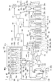
- the raw material fluid processing plant of the present embodiment includes a raw material reaction facility 40 that reacts the raw material fluid NH to generate a reaction gas RG, and a reaction gas utilization facility 10 that uses the reaction gas RG.
- the exhaust heat utilization facility 20 that utilizes the heat of the exhaust gas EG from the reaction gas utilization facility 10 is provided.
- the raw material fluid NH of this embodiment is ammonia.
- the raw material reaction facility 40 thermally decomposes ammonia, which is the raw material fluid NH, to generate a reaction gas RG containing hydrogen and nitrogen.
- the reaction gas utilization facility 10 is a gas turbine facility including a gas turbine 11 that uses the reaction gas RG as fuel.
- the reaction gas utilization facility 10 in this embodiment and the reaction gas utilization facility in each of the following embodiments are also exhaust gas generation facilities that generate exhaust gas EG.
- the exhaust heat utilization facility 20 includes an exhaust heat recovery boiler 21 that generates steam by utilizing the heat of the exhaust gas EG exhausted from the gas turbine 11, and steam turbines 31, 32, 33, etc. that are driven by the steam. Have.
- the raw material reaction facility 40 includes a raw material reaction device 41 and a residual raw material removing device 130.
- the raw material reactor 41 thermally decomposes liquid ammonia NH, which is a raw material fluid, to generate a reaction gas RG containing hydrogen, nitrogen, and residual ammonia.
- the residual raw material removing device 130 removes the residual raw material (residual ammonia) from the reaction gas RG, and discharges the treated reaction gas RGp which is the reaction gas RG from which the residual raw material has been removed.
- the raw material reactor 41 includes an ammonia supply line 42 through which liquid ammonia NH or gaseous ammonia NHg from the ammonia tank T flows, a raw material ammonia pump 43, preheaters 44a and 44b, a reactor 45, and a reaction gas cooler 46. , A reaction gas line 47, a first heat medium line 51, a first heat medium recovery line 52, and a first heat medium booster 53.
- Liquid ammonia NH is stored in the ammonia tank T.
- Liquid ammonia NH is produced, for example, from hydrogen as a raw material.
- This hydrogen is, for example, hydrogen obtained by electrolyzing water using electricity generated by renewable energy such as wind power or sunlight, or hydrogen obtained by steam reforming natural gas. is there. Hydrogen is not as easy to transport and store as liquefied natural gas. Therefore, the hydrogen obtained as described above is used to produce liquid ammonia NH that can be easily transported and stored, and the liquid ammonia NH is stored in the ammonia tank T
- the ammonia supply line 42 has a first ammonia supply line 42a, a second ammonia supply line 42b, and a third ammonia supply line 42c.
- One end of the first ammonia supply line 42a is connected to the ammonia tank T.
- the preheaters 44a and 44b include a first preheater 44a and a second preheater 44b.
- the other end of the first ammonia supply line 42a is connected to the ammonia inlet of the first preheater 44a.
- the first preheater 44a is a heat exchanger.
- the first preheater 44a exchanges heat between the liquid ammonia NH and the second heat medium to heat the liquid ammonia NH to produce gaseous ammonia NHg, while cooling the second heat medium.
- One end of the second ammonia supply line 42b is connected to the ammonia outlet of the first preheater 44a, and the other end of the second ammonia supply line 42b is connected to the ammonia inlet of the second preheater 44b.
- the second preheater 44b is a heat exchanger.
- the second preheater 44b exchanges heat between the gaseous ammonia NHg and the second heat medium to heat the gaseous ammonia NHg while cooling the second heat medium.
- One end of the third ammonia supply line 42c is connected to the ammonia outlet of the second preheater 44b, and the other end of the third ammonia supply line 42c is connected to the ammonia inlet of the reactor 45.
- the first heat medium line 51 is connected to the medium inlet of the reactor 45.
- a first heat medium recovery line 52 is connected to the medium outlet of the reactor 45.
- the first heat medium booster 53 is provided on the first heat medium recovery line 52.
- the reactor 45 is a heat exchanger.
- a catalyst that promotes the thermal decomposition reaction of the raw material fluid is arranged in the region through which the raw material fluid passes in the reactor 45.
- the raw material fluid is ammonia, as described above.
- the catalyst is not arranged in the preheaters 44a and 44b, and the catalyst is arranged in the reactor 45.
- the catalyst is arranged only in the region where the temperature is sufficiently high for the reaction of the raw material fluid to proceed actively, and the catalyst is not arranged in the region where the temperature is low where the reaction does not proceed even if the catalyst is arranged.
- the reaction can be effectively promoted with a small amount of catalyst, and the cost of the catalyst can be reduced.
- the reactor 45 the raw material fluid undergoes an endothermic reaction. According to this embodiment, the heat required for the endothermic reaction can be efficiently supplied.
- the reactor 45 exchanges heat between the gaseous ammonia NHg heated by the second preheater 44b and the first heat medium from the first heat medium line 51 to further heat the gaseous ammonia NHg, while the first heat. Cool the medium.
- the cooled first heat medium flows into the first heat medium recovery line 52.
- the gaseous ammonia NHg heated in the reactor 45 becomes a reaction gas RG containing hydrogen, nitrogen and residual ammonia by a thermal decomposition reaction.
- the reaction gas line 47 has a first reaction gas line 47a, a second reaction gas line 47b, and a third reaction gas line 47c. One end of the first reaction gas line 47a is connected to the reaction gas outlet of the reactor 45. The other end of the first reaction gas line 47a is connected to the second heat medium inlet of the second preheater 44b.
- reaction gas line 47b is connected to the second heat medium outlet of the second preheater 44b, and the other end of the second reaction gas line 47b is connected to the second heat medium inlet of the first preheater 44a.
- One end of the third reaction gas line 47c is connected to the outlet of the second heat medium of the first preheater 44a, and the other end of the third reaction gas line 47c is connected to the residual raw material removing device 130. Therefore, in the present embodiment, the reaction gas RG is the second heat medium. Further, in the present embodiment, the second heat medium line that guides the reaction gas RG, which is the second heat medium, to the first preheater 44a and the second preheater 44b is the reaction gas line 47.
- the reaction gas cooler 46 is provided in the third reaction gas line 47c. The reaction gas cooler 46 cools the reaction gas RG flowing through the third reaction gas line 47c.
- the residual raw material removing device 130 includes an absorption tower 131, a regeneration tower 132, an ammonia water line 133, a water line 134, a water supply pump 135, a heat exchanger 136, a water circulation line 137, a condenser 138, and the like. It has a reboiler 139, a recovered ammonia line 140, and a recovered ammonia booster 141.
- the other end of the reaction gas line 47 is connected to the lower part of the absorption tower 131.
- One end of the water line 134 is connected to the upper part of the absorption tower 131. Water from the water line 134 is sprayed into the absorption tower 131, and the reaction gas RG from the reaction gas line 47 flows into the absorption tower 131. In the absorption tower 131, water and the reaction gas RG come into contact with each other, and the residual ammonia in the reaction gas RG dissolves in water. As a result, the ammonia water, which is the water in which the residual ammonia is dissolved, collects in the lower part of the absorption tower 131.
- the treated reaction gas RGp which is the reaction gas RG from which the residual ammonia has been removed, rises in the absorption tower 131.
- the concentration of ammonia NHg in the gas phase dissolved in water increases as the temperature inside the absorption tower 131 decreases. Therefore, in the present embodiment, the reaction gas RG flowing out of the reactor 45 is sequentially cooled by the second preheater 44b, the first preheater 44a, and the reaction gas cooler 46, and then guided into the absorption tower 131. There is.
- the ammonia water line 133 connects the bottom of the absorption tower 131 and the top of the regeneration tower 132.
- the ammonia water accumulated in the absorption tower 131 is guided into the regeneration tower 132 via the ammonia water line 133.
- One end of the water circulation line 137 is connected to the bottom of the regeneration tower 132, and the other end of the water circulation line 137 is connected to the lower part (above the bottom) of the regeneration tower 132.
- a reboiler 139 is provided in the water circulation line 137. The reboiler 139 exchanges heat between the steam from the exhaust heat utilization facility 20 and the water from the water circulation line 137, cools the steam and condenses it into heated water, while heating the water from the water circulation line 137.
- This steam flows into the regeneration tower 132 via the water circulation line 137.
- the ammonia water is heated by steam, and the ammonia in the ammonia water is separated and distilled as gaseous ammonia NHg.
- the water in the ammonia water collects in the regeneration tower 132.
- a part of the water collected in the regeneration tower 132 flows into the regeneration tower 132 as steam via the water circulation line 137 and the reboiler 139.
- the other end of the water line 134 described above is connected to the water circulation line 137 or the reboiler 139. Therefore, the rest of the water accumulated in the regeneration tower 132 is sent to the absorption tower 131 via the water line 134.
- the water supply pump 135 is provided in this water supply line.
- the heat exchanger 136 heats the ammonia water while cooling the water by exchanging heat between the water flowing through the water line 134 and the ammonia water flowing through the ammonia water line 133.
- One end of the recovered ammonia line 140 is connected to the top of the regeneration tower 132, and the other end of the recovered ammonia line 140 is connected to the second ammonia supply line 42b through which gaseous ammonia NHg flows.
- the recovered ammonia line 140 is provided with a condenser 138 and a recovered ammonia booster 141. Gas containing gaseous ammonia NHg and water flows into the condenser 138 from the regeneration tower 132. The condenser 138 condenses the water contained in the gas from the regeneration tower 132, and returns this water to the regeneration tower 132.
- the gas from which water has been removed by the condenser 138 and the concentration of gaseous ammonia NHg has increased is boosted by the recovery ammonia booster 141, and then passes through the recovery ammonia line 140 and the second ammonia supply line 42b, and is second. It flows into the preheater 44b.
- the reaction gas utilization facility 10 has a fuel line 12 and a fuel preheater 13 in addition to the gas turbine 11 described above.
- the gas turbine 11 includes an air compressor 11a that compresses air to generate combustion air, a combustor 11c that burns fuel in the combustion air to generate combustion gas, and a turbine 11d that is driven by the combustion gas.
- the air compressor 11a has a compressor rotor and a compressor casing that covers the compressor rotor.
- the turbine 11d includes a turbine rotor and a turbine casing that covers the turbine rotor.
- the compressor rotor and the turbine rotor are connected to each other to form a gas turbine rotor.
- a generator is connected to the end of the gas turbine rotor.
- One end of the fuel line 12 is connected to the top of the absorption tower 131, and the other end of the fuel line 12 is connected to the combustor 11c. Therefore, the processed reaction gas RGp generated in the absorption tower 131 is sent to the combustor 11c as fuel.
- the fuel line 12 is provided with a fuel preheater 13.
- the fuel preheater 13 heats the treated reaction gas RGp as a fuel.
- the treated reaction gas RGp heated by the fuel preheater 13 flows into the combustor 11c.
- the reaction gas utilization facility 10 described above has a gas turbine cycle which is a kind of thermal cycle.
- This gas turbine cycle includes a fuel line 12, a fuel preheater 13, and a gas turbine 11.
- the exhaust heat utilization facility 20 includes a condenser 34, a water supply line 35, a water supply pump 36, and a chimney 39, in addition to the exhaust heat recovery boiler 21 and steam turbines 31, 32, 33 described above.
- the exhaust heat utilization facility 20 of the present embodiment has a low pressure steam turbine 31, a medium pressure steam turbine 32, and a high pressure steam turbine 33 as steam turbines 31, 32, 33.
- Each of the steam turbines 31, 32, 33 has a turbine rotor and a turbine casing that covers the turbine rotor.
- the turbine rotors of each steam turbine 31, 32, 33 are connected to each other to form one steam turbine rotor.
- a generator is connected to the end of the steam turbine rotor.
- a condenser 34 is connected to the low-pressure steam turbine 31.
- the condenser 34 returns the steam exhausted from the low-pressure steam turbine 31 to water.
- the water supply line 35 connects the condenser 34 and the exhaust heat recovery boiler 21.
- the water supply pump 36 is provided in the water supply line 35. The water supply pump 36 sends the water in the condenser 34 to the exhaust heat recovery boiler 21 via the water supply line 35.
- the exhaust heat recovery boiler 21 includes a gas frame 22, a first low-pressure economizer 23a, a second low-pressure economizer 23b, a low-pressure evaporator 23c, a low-pressure superheater 23f, a medium-pressure economizer 24a, and the like.
- Exhaust gas EG exhausted from the gas turbine 11 flows in the gas frame 22.
- the gas frame 22 has an inlet and an outlet.
- the exhaust port of the turbine 11d is connected to the inlet of the gas frame 22.
- a chimney 39 is connected to the outlet of the gas frame 22.
- the exhaust gas EG flows through the gas frame 22 from the inlet to the outlet.
- the side where the entrance exists with respect to the exit is the upstream side, and the opposite side is the downstream side.
- the first high-pressure economizer 25a, a part of the low-pressure economizer 23c, the second low-pressure economizer 23b, and the first low-pressure economizer 23a are arranged in the above order from the upstream side to the downstream side in the gas frame 22. It is located inside.
- the medium-pressure economizer 24a is arranged at substantially the same position as the first high-pressure economizer 25a in the flow direction of the exhaust gas EG.
- a water supply line 35 is connected to the first low pressure economizer 23a.
- the first low-pressure economizer 23a heats the water by exchanging heat between the water from the water supply line 35 and the exhaust gas EG.
- the second low-pressure economizer 23b exchanges heat between the water from the first low-pressure economizer 23a and the exhaust gas EG, and further heats this water to obtain low-pressure heated water.
- the low-pressure evaporator 23c exchanges heat between the low-pressure heated water and the exhaust gas EG, and heats the low-pressure heated water into steam.
- the low-pressure superheater 23f exchanges heat between the steam from the low-pressure evaporator 23c and the exhaust gas EG, and heats this steam to obtain low-pressure steam.
- One end of the low pressure steam line 88 is connected to the outlet of the low pressure superheater 23f.
- the other end of the low pressure steam line 88 is connected to the inlet of the low pressure steam turbine 31.
- the medium pressure pump 24p boosts the low pressure heated water.
- the medium-pressure economizer 24a exchanges heat between the heated water boosted by the medium-pressure pump 24p and the exhaust gas EG, and further heats the heated water to obtain medium-pressure heated water.
- An inlet of the medium pressure evaporator 24b is connected to the outlet of the medium pressure economizer 24a, and a medium pressure heating water line 77 is connected to the outlet.
- the medium pressure heated water line 77 is connected to the medium inlet of the fuel preheater 13 described above.
- the fuel preheater 13 heats the treated reaction gas RGp by exchanging heat between the medium pressure heated water from the medium pressure heated water line 77 and the treated reaction gas RGp as fuel, while heating the medium pressure heated water. Cooling.
- a heated water recovery line 78 is connected to the medium outlet of the fuel preheater 13.
- the heated water recovery line 78 is connected to the water supply line 35.
- the medium pressure evaporator 24b exchanges heat between the medium pressure heated water and the exhaust gas EG to heat the medium pressure heated water into medium pressure steam.
- a medium line 71 for the first reboiler is connected to the outlet of the medium pressure evaporator 24b.
- the medium line 71 for the first reboiler is connected to the medium inlet of the reboiler 139 described above.
- a media recovery line 73 for the reboiler is connected to the medium outlet of the reboiler 139.
- the reboiler medium recovery line 73 is connected to the inlet of the medium pressure economizer 24a.
- the reboiler medium recovery line 73 is provided with a reboiler medium booster 74.
- the high pressure pump 25p boosts the low pressure heating water.
- the first high-pressure economizer 25a exchanges heat between the heated water boosted by the high-pressure pump 25p and the exhaust gas EG to further heat the heated water.
- the second high-pressure economizer 25b exchanges heat between the heated water heated by the first high-pressure economizer 25a and the exhaust gas EG to further heat the heated water.
- the high-pressure evaporator 25c exchanges heat between the heated water heated by the second high-pressure economizer 25b and the exhaust gas EG, and heats the heated water into steam.
- the high-pressure superheater 25d exchanges heat between the steam and the exhaust gas EG, and further superheats the steam to obtain high-pressure steam.
- One end of the high pressure steam line 83 is connected to the outlet of the high pressure superheater 25d.
- the other end of the high pressure steam line 83 is connected to the inlet of the high pressure steam turbine 33.
- One end of the high-pressure exhaust steam line 85 is connected to the outlet of the high-pressure steam turbine 33.
- the other end of the high pressure exhaust steam line 85 is connected to the inlet of the medium pressure steam turbine 32.
- a medium line 72 for a second reboiler is connected to the high-pressure exhaust steam line 85.
- the medium line 72 for the second reboiler is connected to the medium inlet of the reboiler 139 described above. Therefore, in addition to the above-mentioned first revolving medium line 71, the second revolving medium line 72 is connected to the medium inlet of the reboiler 139.
- One end of the medium pressure exhaust steam line 87 is connected to the outlet of the medium pressure steam turbine 32.
- the other end of the medium pressure exhaust steam line 87 is connected to the inlet of the low pressure steam turbine 31. Therefore, the medium pressure exhaust steam line 87 and the low pressure steam line 88 are connected to the inlet of the low pressure steam turbine 31.
- the first heat medium recovery line 52 is connected to the medium inlet of the first heat medium heater 27.
- the first heat medium recovery line 52 and the high-pressure steam line 83 are connected by a heat medium replenishment line 55.
- the first heat medium, the heat cycle medium, and the high-pressure steam that is the operating medium of the high-pressure steam turbine are all steam and are the same substance.
- the pressure of the first heat medium is lower than the maximum pressure of the heat cycle medium in the exhaust heat utilization heat cycle.
- the pressure of the first heat medium is lower than the steam pressure at the inlet of the high pressure steam turbine.
- the heat medium replenishment line 55 is provided with a heat medium replenishment valve 56.
- the heat medium replenishment valve 56 is closed, but when it is necessary to replenish the first heat medium, such as when the pressure of the first heat medium drops due to a start-up or leakage of the first heat medium, the heat medium is replenished.
- the replenishment valve 56 is opened.
- high-pressure steam is appropriately supplied from the high-pressure steam line 83 as the first heat medium to the first heat medium recovery line 52 via the heat medium replenishment line 55 and the heat medium replenishment valve 56.
- a first heat medium line 51 is connected to the medium outlet of the first heat medium heater 27.
- the first heat medium heater 27 heats the first heat medium by exchanging heat between the first heat medium from the first heat medium recovery line 52 and the exhaust gas EG.
- the first heat medium heated by the first heat medium heater 27 flows into the reactor 45 via the first heat medium line 51.
- the first heat medium is cooled by heat exchange with the gaseous ammonia NHg in the reactor 45.
- the cooled first heat medium returns to the first heat medium heater 27 via the first heat medium recovery line 52.
- the first heat medium is boosted by the first heat medium booster 53 in this process.
- the first heat medium is the same substance as the operating medium of the high-pressure steam turbine, that is, steam, and the pressure of the first heat medium is lower than the inlet pressure of the high-pressure steam turbine. You may.
- a heat medium replenishment line 55 connecting a line for sending steam to the high-pressure steam turbine 33 and a first heat medium recovery line 52, and a heat medium replenishment valve 56.
- the heat medium replenishment line 55 and the heat medium replenishment valve 56 are provided, the heat medium replenishment line 55 and the heat medium replenishment valve 56 are provided at the time of starting or when the pressure of the first heat medium drops, etc.
- the first heat medium can be replenished.
- the exhaust heat utilization facility 20 described above has the Rankine cycle, which is a kind of heat cycle.
- This Rankine cycle includes an exhaust heat recovery boiler 21, steam turbines 31, 32, 33, a condenser 34, and a water supply pump 36. Since this Rankine cycle utilizes the heat of the exhaust gas EG, it is also an exhaust heat utilization heat cycle.
- start-up fuel is supplied to the combustor 11c from a start-up fuel line (not shown).
- the start-up fuel include hydrogen and natural gas.
- the air compressor 11a of the gas turbine 11 compresses the air to generate combustion air.
- the combustor 11c burns the fuel at startup during this combustion to generate combustion gas.
- the pressure of the combustion air is, for example, about 2 MPa. Therefore, the pressure in the combustor 11c into which the combustion air has flowed is also, for example, about 2 MPa.
- the combustion gas is supplied to the turbine 11d to drive the turbine 11d.
- the exhaust gas EG which is the combustion gas that drives the turbine 11d, flows into the gas frame 22 of the exhaust heat recovery boiler 21.
- the first low-pressure economizer 23a heats this water by exchanging heat between the water from the water supply line 35 and the exhaust gas EG.
- the second low-pressure economizer 23b exchanges heat between the water from the first low-pressure economizer 23a and the exhaust gas EG, and further heats this water to obtain low-pressure heated water.
- a part of this low-pressure heating water is boosted by the high-pressure pump 25p and then flows into the first high-pressure economizer 25a.
- the first high-pressure economizer 25a exchanges heat between the heated water boosted by the high-pressure pump 25p and the exhaust gas EG to further heat the heated water.
- the second high-pressure economizer 25b exchanges heat between the heated water heated by the first high-pressure economizer 25a and the exhaust gas EG to further heat the heated water.
- the high-pressure evaporator 25c exchanges heat between the heated water heated by the second high-pressure economizer 25b and the exhaust gas EG, and heats the heated water into steam.
- the high-pressure superheater 25d exchanges heat between the steam and the exhaust gas EG, and further superheats the steam to obtain high-pressure steam.
- This high-pressure steam flows into the high-pressure steam turbine 33 via the high-pressure steam line 83.
- the high-pressure steam turbine 33 is driven by the high-pressure steam.
- a part of the high-pressure steam that drives the high-pressure steam turbine 33 flows into the medium-pressure steam turbine 32 via the high-pressure exhaust steam line 85. Further, the other part of the high-pressure steam that drives the high-pressure steam turbine 33 flows into the riboira 139 via the medium line 72 for the second riboira.
- the medium pressure steam turbine 32 is driven by steam from the high pressure exhaust steam line 85.
- the steam that drives the medium-pressure steam turbine 32 flows into the low-pressure steam turbine 31 via the medium-pressure exhaust steam line 87.
- the other part of the low-pressure heated water described above flows into the low-pressure evaporator 23c.
- the low-pressure evaporator 23c exchanges heat between the low-pressure heated water and the exhaust gas EG, and heats the low-pressure heated water into steam.
- the low-pressure superheater 23f exchanges heat between the steam from the low-pressure evaporator 23c and the exhaust gas EG, and heats this steam to obtain low-pressure steam.
- This low-pressure steam flows into the low-pressure steam turbine 31 via the low-pressure steam line 88.
- the steam driving the medium-pressure steam turbine 32 also flows into the low-pressure steam turbine 31 as described above.
- the low pressure steam turbine 31 is driven by this steam.
- the steam that drives the low-pressure steam turbine 31 flows into the condenser 34.
- the condenser 34 returns the steam from the low pressure steam turbine 31 to water. This water flows into the first low-pressure economizer 23a via the water supply line 35.
- the other part of the low-pressure heated water described above is boosted by the medium-pressure pump 24p and then flows into the medium-pressure economizer 24a.
- the medium-pressure economizer 24a exchanges heat between the heated water boosted by the medium-pressure pump 24p and the exhaust gas EG, and further heats the heated water to obtain medium-pressure heated water.
- a part of the medium-pressure heating water flows into the fuel preheater 13 via the medium-pressure heating water line 77.
- the heated water that has flowed into the fuel preheater 13 flows into the water supply line 35 via the heated water recovery line 78.
- the other part of the medium pressure heated water flows into the medium pressure evaporator 24b.
- the medium-pressure evaporator 24b exchanges heat between the medium-pressure heated water and the exhaust gas EG to heat the medium-pressure heated water into medium-pressure steam.
- This medium-pressure steam flows into the reboiler 139 via the medium line 71 for the first reboiler. That is, in addition to the steam from the first revolving medium line 71, the steam from the second revolving medium line 72 also flows into the reboiler 139 as described above.
- the steam that has flowed into the reboiler 139 becomes water and then flows into the medium pressure economizer 24a via the reboiler medium recovery line 73.
- the first heat medium heater 27 exchanges heat between steam and exhaust gas EG to raise the temperature of this steam.
- the steam after the temperature rise flows into the reactor 45 via the first heat medium line 51.
- This steam flows into the first heat medium heater 27 via the first heat medium recovery line 52 without changing the phase.
- This steam circulates as the first heat medium between the first heat medium heater 27 and the reactor 45 while the exhaust gas EG is flowing in the gas frame 22.
- a heat cycle medium which is water or steam circulates.
- the liquid ammonia NH in the ammonia tank T is supplied to the raw material reaction facility 40.
- the operation of the raw material fluid processing plant will be described with reference to the flowchart shown in FIG.
- Liquid ammonia NH is supplied to the raw material reaction facility 40, and steam as the first heat medium flows into the reactor 45. Further, steam as a medium for the reboiler flows into the reboiler 139.
- the raw material reaction step (S1) When the liquid ammonia NH is supplied to the raw material reaction facility 40, the raw material reaction step (S1) is executed. In this raw material reaction step (S1), a reaction gas generation step (S2) and a residual raw material removal step (S6) are executed. In the reaction gas generation step (S2), the raw material preheating step (S3), the reaction execution step (S4), and the reaction gas cooling step (S5) are executed.
- Liquid ammonia NH is stored in the ammonia tank T in a state of being cooled to a boiling point of -33.4 ° C. or lower and in a state of almost atmospheric pressure.
- the liquid ammonia NH in the ammonia tank T is boosted to, for example, about 5 MPa by the raw material ammonia pump 43, then flows into the preheaters 44a and 44b, and is used as the second heat medium in the preheaters 44a and 44b. It is preheated by heat exchange of (S3: raw material preheating step).
- S3 raw material preheating step
- liquid ammonia NH is vaporized to gaseous ammonia NHg.
- Liquid ammonia NH is vaporized to gaseous ammonia NHg at 90 ° C. or higher in a pressure environment boosted by the raw material ammonia pump 43. Therefore, the first preheater 44a preheats the liquid ammonia NH so that the liquid ammonia NH becomes 90 ° C. or higher. Therefore, the first preheater 44a functions as a vaporizer for liquid ammonia NH.
- the gaseous ammonia NHg flows into the second preheater 44b, where it is preheated to, for example, about 400 ° C. Therefore, the second preheater 44b functions as a gas heater for the gaseous ammonia NHg.
- the gaseous ammonia NHg from the second preheater 44b flows into the reactor 45. Further, steam, which is the first heat medium heated by the first heat medium heater 27 of the exhaust heat recovery boiler 21, flows into the reactor 45 via the first heat medium line 51. This steam is, for example, about 620 ° C.
- the heat exchange between the gaseous ammonia NHg and the first heat medium further heats the gaseous ammonia NHg while cooling the first heat medium.
- the cooled first heat medium returns to the first heat medium recovery line 52 via the first heat medium recovery line 52.
- This first heat medium circulates between the reactor 45 and the first heat medium heater 27.
- the first heat medium does not undergo a phase change in the process of circulating between the reactor 45 and the first heat medium heater 27.
- the gaseous ammonia NHg heated in the reactor 45 is decomposed into hydrogen and nitrogen by the thermal decomposition reaction represented by the following formula (S4: reaction execution step).
- S4 reaction execution step
- reaction execution step (S4) a part of the gaseous ammonia NHg flowing into the reactor 45 remains as residual ammonia (residual raw material). Therefore, residual ammonia remains in the reaction gas RG obtained in the execution of this reaction execution step (S3) in addition to hydrogen and nitrogen.
- the reaction gas RG is about 600 ° C.
- This reaction gas RG sequentially flows into the second preheater 44b, the first preheater 44a, and the reaction gas cooler 46, and is cooled sequentially by passing through these (S5: reaction gas cooling step).
- the reaction gas RG from the reactor 45 flows into the second preheater 44b as the second heat medium through the reaction gas line 47, which is also the second heat medium line.
- the gas ammonia NHg is preheated as described above by the heat exchange between the gaseous ammonia NHg and the reaction gas RG, while the reaction gas RG is cooled.
- the reaction gas RG cooled by the first preheater 44a flows into the first preheater 44a as the second heat medium through the reaction gas line 47, which is also the second heat medium line.
- the liquid ammonia NH is preheated and vaporized as described above by heat exchange between the liquid ammonia NH and the reaction gas RG, while the reaction gas RG is further cooled.
- the reaction gas RG cooled by the first preheater 44a flows into the reaction gas cooler 46 and is further cooled.
- the temperature of this reaction gas RG is, for example, about 30 to 50 ° C.
- the second preheater 44b and the first preheater 44a of the present embodiment function as a preheater for preheating ammonia NH and also as a reaction gas cooler for cooling the reaction gas RG.
- the reaction gas RG here is a second heat medium for preheating ammonia NH
- the ammonia NH is a third heat medium for cooling the reaction gas RG.
- reaction gas generation step (S2) is completed.
- the residual raw material removal step (S6) is executed.
- the residual raw material removal step (S6) the residual raw material absorption step (S7) and the residual raw material separation step (S8) are executed.
- the residual raw material absorption step (S7) is executed in the absorption tower 131.
- the reaction gas RG from the raw material reactor 41 flows into the absorption tower 131. Further, water at about 30 ° C. is sprayed on the absorption tower 131 from the water line 134.
- the reaction gas RG and water come into contact with each other in the absorption tower 131, and the residual ammonia in the reaction gas RG dissolves in water.
- Ammonia water which is water in which residual ammonia is dissolved, collects in the lower part of the absorption tower 131.
- the treated reaction gas RGp which is the reaction gas RG from which the residual ammonia has been removed, is sent to the gas turbine 11 via the fuel line 12.
- the raw material water heating step (S9) In the residual raw material separation step (S8), the raw material water heating step (S9), the raw material separation execution step (S10), and the water heating step (S11) are executed.
- Ammonia water (raw material water) collected in the lower part of the absorption tower 131 is sent to the regeneration tower 132 via the ammonia water line 133.
- the ammonia water is heated in the heat exchanger 136 (S9: raw material water heating step).
- steam from the reboiler 139 also flows into the regeneration tower 132.
- Ammonia water is heated by this steam, and ammonia in the ammonia water is separated and distilled as gaseous ammonia NHg (S10: raw material separation execution step).
- the vapor migrates to the liquid phase water and accumulates in the lower part of the regeneration tower 132.
- a part of this water flows into the reboiler 139 via the water circulation line 137.
- the medium-pressure steam from the medium-pressure evaporator 24b flows into the reboiler 139 via the medium-pressure medium line 71 for the first reboiler, and the steam exhausted from the high-pressure steam turbine 33 passes through the medium line 72 for the second reboiler. Inflow.
- the water flowing in from the water circulation line 137 is heated by heat exchange with steam to become steam (S11: water heating step). This steam is sent to the regeneration tower 132.
- the steam that has exchanged heat with the water that has flowed in from the water circulation line 137 is cooled and flows into the medium pressure economizer 24a as heated water via the reboiler medium recovery line 73.
- the gas containing gaseous ammonia NHg in the regeneration tower 132 flows into the condenser 138 via the recovered ammonia line 140.
- this gas is cooled, and the water contained in this gas is condensed into liquid water. This water returns to the inside of the regeneration tower 132.
- the gas from which water has been removed that is, the gas having a high gaseous ammonia concentration, is boosted by the recovered ammonia booster 141 provided in the recovered ammonia line 140, and then the recovered ammonia line 140 and the second ammonia supply line 42b. It flows into the second preheater 44b via the above (S12: raw material recovery step).
- the residual ammonia removed from the reaction gas RG by the residual raw material removing device 130 returns to the second preheater 44b, so that the amount wasted in the ammonia as the raw material is minimized. It can be suppressed.
- the processed reaction gas RGp is sent to the gas turbine 11 via the fuel line 12.
- the treated reaction gas RGp is preheated by the fuel preheater 13 in this process.
- the gas turbine 11 is driven by burning the processed reaction gas RGp as fuel (S13: reaction gas utilization step).
- the exhaust gas EG from the gas turbine 11 flows into the exhaust heat recovery boiler 21 of the exhaust heat utilization facility 20.
- the exhaust heat utilization facility 20 uses the heat of the exhaust gas EG to heat the heat cycle medium flowing in the exhaust heat utilization heat cycle, and utilizes the heated heat cycle medium (S14: exhaust heat utilization step). ). That is, in the exhaust heat utilization facility 20, water is heated by the exhaust gas EG to become steam, and this steam is used to drive the steam turbines (medium utilization equipment) 31, 32, 33. In this waste heat utilization step (S14), the first heat medium heating step (S15), the heat cycle medium heating step (S16), and the heat cycle medium utilization step (S17) are executed.
- the exhaust gas EG flowing into the gas frame 22 heats the first heat medium by heat exchange with steam, which is the first heat medium, in the first heat medium heater 27 as described above (S14: No. 1). 1 Heat medium heating process).
- the steam heated by the first heat medium heater 27 is sent to the reactor 45.
- the gaseous ammonia NHg flowing into the reactor 45 at this time and the steam which is the first heat medium exchange heat, and the gaseous ammonia NHg is heated.
- the gaseous ammonia NHg heated in the reactor 45 becomes a reaction gas RG by a thermal decomposition reaction (S4: reaction execution step).
- the exhaust gas EG flowing into the exhaust heat recovery boiler 21 heats the heat cycle medium by heat exchange with the heat cycle medium which is steam or water, and each steam turbine 31, 32, 33 (S16: Heat cycle medium heating step). This steam is sent to each steam turbine 31, 32, 33 to drive each steam turbine 31, 32, 33 (S17: thermal cycle medium utilization step).
- FIGS. 3 and 4 are TQ diagrams relating to ammonia (solid line) and a heat source for heating ammonia (broken line). Therefore, in FIGS. 3 and 4, the horizontal axis represents the amount of heat and the vertical axis represents the temperature.
- FIG. 3 is a TQ diagram relating to ammonia and a heat source until the liquid ammonia is thermally decomposed by one heat exchange device as in Patent Documents 1 and 2 described above.
- FIG. 4 is a TQ diagram relating to ammonia and a heat source until the liquid ammonia is thermally decomposed in the present embodiment.
- the temperature of liquid ammonia increases as the amount of heat increases due to preheating.
- the temperature of the liquid ammonia reaches the saturation temperature, the liquid ammonia gradually vaporizes. In this process of vaporization, even if the amount of heat of ammonia increases, this heat is used as heat of vaporization (latent heat), and the temperature of ammonia does not change.
- preheating increases the amount of heat and the temperature.
- the temperature of gaseous ammonia rises to some extent, the pyrolysis reaction begins.
- this pyrolysis reaction is an endothermic reaction, the amount of increase in temperature with respect to the amount of increase in calorific value is smaller than the process of preheating gaseous ammonia. However, as the thermal decomposition reaction proceeds and the concentration of ammonia decreases, the amount of increase in temperature with respect to the amount of increase in calorific value gradually increases.
- the only heat source that thermally decomposes liquid ammonia is the exhaust gas that passes through the gas frame of this heat exchanger.
- the exhaust gas as a heat source gradually decreases in heat amount and temperature as it goes from the inlet in to the outlet out of the gas frame, as compared with the heat exchange with ammonia.
- the amount of decrease in temperature with respect to the amount of decrease in the amount of heat related to the exhaust gas as a heat source is substantially constant regardless of whether ammonia undergoes a thermal decomposition reaction or liquid ammonia is vaporized.
- the temperature difference ⁇ T1 between the ammonia during vaporization and the exhaust gas exchanging heat with the ammonia becomes large, and the heat of the high temperature exhaust gas is recovered by the low temperature ammonia. , The heat utilization efficiency of exhaust gas is low.
- the heat sources for thermally decomposing the liquid ammonia are the first heat medium heated by the exhaust gas EG and the second heat medium which is the reaction gas RG.
- the system through which the second heat medium flows is different from the system through which the first heat medium flows.
- the heat of the first heat medium, which is part of the heat source, is used to pyrolyze ammonia.
- the temperature of the first heat medium during this pyrolysis reaction decreases as the amount of heat decreases and the temperature decreases due to heat exchange with ammonia.
- the amount of decrease in temperature with respect to the amount of decrease in the amount of heat related to the first heat medium as the heat source is almost constant.
- the heat of the second heat medium which is another part of the heat source, is used to preheat ammonia.
- the second heat medium at the time of preheating reduces the amount of heat and the temperature due to heat exchange with ammonia.
- the TQ line indicating the change in temperature with respect to the change in the amount of heat of the second heat medium as a heat source is ammonia. It becomes a line along the TQ line showing the change in temperature with respect to the change in the amount of heat.
- the temperature difference ⁇ T2 between the ammonia and the second heat medium at the time of preheating becomes smaller, and the ammonia recovers the heat of the second heat medium close to the temperature of the ammonia, so that the heat utilization efficiency of the second heat medium becomes higher. It gets higher.
- the reaction gas RG and ammonia as the second heat medium are formed on the TQ line of ammonia until just before the reaction region including the temperature at which the inclination becomes the minimum P.
- Ammonia is preheated by exchanging heat with and.
- ammonia is thermally decomposed by the heat of steam as the first heat medium in the reaction region. Therefore, in the present embodiment, the amount of heat for heating the first heat medium can be reduced as compared with the case where ammonia is preheated and thermally decomposed with one heat medium. Therefore, in the present embodiment, it is possible to suppress the thermal energy loss of the exhaust gas EG for heating the first heat medium.
- the slope of the TQ line of ammonia is small as described above.
- the endothermic reaction does not occur, so the slope of the TQ line is large on average. Therefore, the product of the constant pressure specific heat of the steam, which is the first heat medium, which is the heat source of the reactor 45, and the flow rate is the heat source of the preheater 44 composed of the second preheater 44b and the first preheater 44a.
- the first heat medium is circulated so as to be larger than the product of the constant pressure specific heat of the reaction gas RG and the flow rate.
- the product of the constant pressure specific heat and the flow rate that is, the heat capacity of the heat medium per unit time can be considered in units of kW / K. it can.
- the unit of the constant pressure specific heat and the flow rate may be any as long as the same unit is used for the first heat medium and the second heat medium.
- the constant pressure specific heat is in units of kcal / molK and the flow rate is in units of mol / h. Considering this, the product of the constant pressure specific heat and the flow rate may be calculated in kcal / hK and compared.
- the slope of the TQ line is inversely proportional to the product of the constant pressure specific heat and the flow rate, and the larger the product of the constant pressure specific heat and the flow rate, the smaller the slope of the TQ line. Therefore, at this time, the product of the constant pressure specific heat of the steam, which is the first heat medium, and the flow rate is larger than the product of the constant pressure specific heat and the flow rate of the second heat medium, that is, the reaction gas RG, which is the heat source of the preheater 44. In addition, the first heat medium is circulated.
- the inclination of the TQ line of the first heat medium and the second heat medium can be brought close to the inclination of the TQ line of ammonia, and the temperature difference ⁇ T2 between ammonia and the second heat medium at the time of preheating can be reduced.
- the heat of the second heat medium can be recovered to ammonia at a temperature close to that of ammonia, and the amount of heat required for each temperature level can be input in just proportion. Therefore, heat can be effectively used according to the temperature level, and the heat utilization efficiency of the second heat medium becomes high.
- the above effect is exerted on the raw material fluid, that is, the inclination of the TQ line of ammonia differs between the reaction and the preheating, whereas the first heat medium and the second heat medium, which are the heat media for the reaction and the preheating, respectively.
- This is the effect obtained by performing the following a) and b) using different media.
- the heat capacities of the first heat medium and the second heat medium per unit time that is, the slopes of the TQ lines are made different, and the slopes of the TQ lines of the first heat medium and the second heat medium are different, respectively. It was used for the slope of the TQ line of ammonia in the reactor and the slope of the TQ line of ammonia in the preheater.
- As the first heat medium and the second heat medium those having a temperature close to that of ammonia in the reactor and the preheater were used, respectively.
- the first heat medium and the second heat medium need to be different heat media from each other.
- the first heat medium is steam and the second heat medium is a reaction gas, both of which are different substances, but the types of substances in the heat medium do not necessarily have to be different, and they are the same substance.
- the heat capacity per unit time may be different, or the temperature may be different depending on the phase, flow rate, pressure, and the like.
- the slope of the TQ line of the heat medium can be changed so that the slope of the raw material fluid of each of the reactor and the preheater can be made close to the TQ line. ..
- the first heat medium circulates between the reactor 45 and the first heat medium heater 27. Therefore, the temperature difference between the temperature of the first heat medium flowing out of the first heat medium heater 27 and the temperature of the first heat medium flowing into the first heat medium heater 27 can be minimized. Moreover, as described above, the first heat medium of the present embodiment does not undergo a phase change in the process of circulating between the reactor 45 and the first heat medium heater 27. Therefore, in the present embodiment, the amount of heat for heating the first heat medium can be reduced from this viewpoint as well.
- the temperature of the exhaust gas EG for heating the first heat medium is higher than the temperature of the exhaust gas EG for generating steam to be sent to the steam turbines 31, 32, 33. Therefore, as described above, if the amount of heat for heating the first heat medium can be reduced, the heat energy loss of the high-temperature exhaust gas EG can be suppressed.
- the thermal energy loss of the exhaust gas EG can be suppressed. Therefore, in the present embodiment, the thermal energy can be increased to drive the steam turbines 31, 32, 33 in the thermal energy of the exhaust gas EG, and the thermal efficiency of the plant can be improved.
- the heat cycle medium flowing in the waste heat utilization heat cycle and the first heat medium are water of the same substance, it is possible to easily control the quality of the water which is the first heat medium. it can.
- the pressure of steam which is the first heat medium
- the pressure of steam is lower than the maximum pressure of the heat cycle medium in the exhaust heat utilization heat cycle. Therefore, a part of the heat cycle medium is easily supplied to the system of the first heat medium as the first heat medium from the exhaust heat utilization heat cycle at the time of starting or when the pressure of the first heat medium drops without the need for separate equipment.
- the first heat medium can be replenished.
- the high-pressure steam is used as the first heat medium from the high-pressure steam line 83, which constitutes a part of the waste heat utilization heat cycle, via the heat medium replenishment line 55 and the heat medium replenishment valve 56. It is supplied to the first heat medium recovery line 52. During normal operation, the heat medium replenishment valve 56 is closed.
- the pressure of steam which is the first heat medium
- the pressure of high-pressure steam which is the heat cycle medium in the exhaust heat utilization heat cycle.
- the heat medium replenishment valve 56 is opened and a part of the high pressure steam flowing through the high pressure steam line 83 is introduced.
- the first heat medium is replenished to the first heat medium recovery line 52 and the like.
- the first heat medium can be easily replenished at the time of starting up or when the pressure of the first heat medium drops without requiring a separate facility.
- the heat cycle medium flowing in the exhaust heat utilization heat cycle and the first heat medium are made of the same substance, and the pressure of steam, which is the first heat medium, is used in the exhaust heat utilization heat cycle. Since the pressure is lower than the maximum pressure of the heat cycle medium, the effect that the first heat medium can be easily replenished from the exhaust heat utilization heat cycle can be obtained. Therefore, as with the first heat medium, the second heat medium is made of the same material as the heat cycle medium flowing in the exhaust heat utilization heat cycle, and the pressure of the second heat medium is the same as that of the heat cycle medium in the exhaust heat utilization heat cycle. If the pressure is lower than the maximum pressure, the effect that the second heat medium can be easily replenished from the exhaust heat utilization heat cycle can be obtained.
- the first heat medium and the second heat medium are not provided with an element for extracting work by expansion of at least one of the heat media, and without having a medium introduction port into which the medium flows from the outside during normal operation.
- a closed loop is composed of heat exchange elements, piping, and booster elements
- the heat medium flowing through the closed loop is made of the same material as the heat cycle medium, and the pressure of the heat medium is higher than the maximum pressure of the heat cycle medium in the exhaust heat utilization heat cycle.
- the pressure low By setting the pressure low, the same effect as described above can be obtained. That is, even when the heat medium is a closed loop, the first heat medium can be easily replenished at the time of starting up or when the pressure of the first heat medium drops without the need for separate equipment.
- the raw material reaction facility 40 of the present embodiment removes residual raw materials for removing residual ammonia contained in the reaction gas RG from the raw material reaction device 41 in addition to the raw material reaction device 41 for thermally decomposing ammonia NH.
- the device 130 is provided. Therefore, in the present embodiment, the concentration of residual ammonia contained in the gas sent to the reaction gas utilization facility 10 can be suppressed.
- the raw material reaction facility 40 of the present embodiment can suppress the concentration of residual ammonia contained in the gas sent to the reaction gas utilization facility 10.
- the reaction gas utilization facility 10 of the present embodiment is a gas turbine facility that burns gas from the raw material reaction facility 40 as fuel. Therefore, in the present embodiment, the NOx concentration in the exhaust gas EG generated by the combustion of fuel can be suppressed. Further, in the present embodiment, the CO2 concentration in the exhaust gas EG generated by the combustion of fuel can be suppressed.
- the raw material fluid processing plant of the present embodiment is a plant in which the heat source for preheating ammonia NH and the heat source for cooling the reaction gas RG are changed from those of the raw material fluid processing plant of the first embodiment. Therefore, the raw material preheating step in the series of operations in the raw material fluid processing plant of the present embodiment is different from the raw material preheating step (S3) of the first embodiment. Further, the reaction gas cooling step in the series of operations in the raw material fluid processing plant of the present embodiment is different from the reaction gas cooling step (S5) of the first embodiment.
- the raw material fluid processing plant of the present embodiment also includes the raw material reaction facility 40a, the reaction gas utilization facility 10, and the exhaust heat utilization facility 20a, as in the first embodiment.
- the raw material reaction facility 40a of the present embodiment has a raw material reaction device 41a and a residual raw material removal device 130, similarly to the raw material reaction facility 40 of the first embodiment.
- the raw material reaction device 41a of the present embodiment is different from the raw material reaction device 41 of the first embodiment.
- the residual raw material removing device 130 of the present embodiment is the same as the residual raw material removing device 130 of the first embodiment.
- the reaction gas utilization facility 10 of the present embodiment is basically the same as the reaction gas utilization facility 10 of the first embodiment.
- the individual devices constituting the exhaust heat utilization facility 20a in the present embodiment are the same as the individual devices constituting the exhaust heat utilization facility 20 in the first embodiment.
- the line configuration connecting the individual devices in the present embodiment is different from the line configuration connecting the individual devices in the first embodiment.
- the raw material reactor 41a of the present embodiment like the raw material reactor 41 of the first embodiment, includes an ammonia supply line 42, a raw material ammonia pump 43, preheaters 44c and 44d, a reactor 45, and a reaction gas cooler. It has 46 and a reaction gas line 47.
- the preheaters 44c and 44d have a first preheater 44c and a second preheater 44d as in the embodiment.
- the reaction gas coolers 46a and 46b include a first reaction gas cooler 46a and a second reaction gas cooler 46b.
- the ammonia supply line 42 has a first ammonia supply line 42a, a second ammonia supply line 42b, and a third ammonia supply line 42c, as in the first embodiment.
- One end of the first ammonia supply line 42a is connected to the ammonia tank T, and the other end of the first ammonia supply line 42a is connected to the ammonia inlet of the first preheater 44c.
- the first preheater 44c is a heat exchanger. The first preheater 44c exchanges heat between the liquid ammonia NH and the second heat medium to heat the liquid ammonia NH to produce gaseous ammonia NHg, while cooling the second heat medium.
- One end of the second ammonia supply line 42b is connected to the ammonia outlet of the first preheater 44c, and the other end of the second ammonia supply line 42b is connected to the ammonia inlet of the second preheater 44d.
- the second preheater 44d is a heat exchanger. The second preheater 44d exchanges heat between the gaseous ammonia NHg and the second heat medium to heat the gaseous ammonia NHg while cooling the second heat medium.
- One end of the third ammonia supply line 42c is connected to the ammonia outlet of the second preheater 44d, and the other end of the third ammonia supply line 42c is connected to the ammonia inlet of the reactor 45.
- the first heat medium line 51 is connected to the medium inlet of the reactor 45.
- a first heat medium recovery line 52 is connected to the medium outlet of the reactor 45.
- the first heat medium booster 53 is provided on the first heat medium recovery line 52.
- the reactor 45 is a heat exchanger. Similar to the reactor 45 of the first embodiment, the reactor 45 exchanges heat between the gaseous ammonia NHg heated by the second preheater 44d and the first heat medium from the first heat medium line 51 to exchange gas with the gas.
- the first heat medium is cooled while further heating the ammonia NHg.
- the cooled first heat medium flows into the first heat medium recovery line 52.
- the first heat medium line 51 and the first heat medium recovery line 52 are both connected to the first heat medium heater 27 of the exhaust heat recovery boiler 21 as in the first embodiment.
- the reaction gas line 47 has a first reaction gas line 47a and a second reaction gas line 47b.
- One end of the first reaction gas line 47a is connected to the reaction gas outlet of the reactor 45.
- the other end of the first reaction gas line 47a is connected to the second heat medium inlet of the second preheater 44d. Therefore, in the present embodiment, the reaction gas RG is a kind of the second heat medium.
- the first reaction gas cooler 46a is provided in the first reaction gas line 47a.
- One end of the second reaction gas line 47b is connected to the second heat medium outlet of the second preheater 44d, and the other end of the second reaction gas line 47b is connected to the residual raw material removing device 130.
- the second reaction gas cooler 46b is provided in the second reaction gas line 47b.
- the high-pressure steam line connecting the high-pressure superheater 25d of the exhaust heat recovery boiler 21 and the high-pressure steam turbine 33 has a first high-pressure steam line 83a and a second high-pressure steam line 83b.
- One end of the first high-pressure steam line 83a is connected to the outlet of the high-pressure superheater 25d, and the other end of the first high-pressure steam line 83a is connected to the third heat medium inlet of the first reaction gas cooler 46a. ..
- One end of the second high-pressure steam line 83b is connected to the third heat medium outlet of the first reaction gas cooler 46a, and the other end of the second high-pressure steam line 83b is connected to the inlet of the high-pressure steam turbine 33. ..
- the high-pressure steam from the high-pressure superheater 25d is a kind of the third heat medium.
- the first high-pressure steam line 83a is a kind of third heat medium line.
- the second high-pressure steam line 83b is a kind of third heat medium recovery line.
- One end of the high-pressure heated water line 81 is connected to the outlet of the second high-pressure economizer 25b in the exhaust heat recovery boiler 21.
- the other end of the high-pressure heating water line 81 is connected to the medium inlet of the fuel preheater 13.
- One end of the high-pressure heated water recovery line 82 is connected to the medium outlet of the fuel preheater 13.
- the other end of the high-pressure heated water recovery line 82 is connected to the water supply line 35. Therefore, the fuel preheater 13 of the present embodiment heats the fuel by exchanging heat between the high-pressure heating water from the second high-pressure economizer 25b and the fuel.
- a branched water supply line 91 branched from the water supply line 35 is connected to the third heat medium inlet of the second reaction gas cooler 46b.
- One end of the connected water supply line 92 is connected to the third heat medium outlet of the second reaction gas cooler 46b.
- the other end of the connected water supply line 92 is connected to the second heat medium inlet of the first preheater 44c. Therefore, in the present embodiment, the water supply flowing through the water supply line 35 is a kind of the third heat medium that exchanges heat with the reaction gas RG.
- the branched water supply line 91 is a kind of third heat medium line.
- the connected water supply line 92 is a kind of a third heat medium recovery line for the second reaction gas cooler 46b.
- the water supply flowing into the first preheater 44c from the connected water supply line 92 is a kind of the second heat medium.
- the connected water supply line 92 is a kind of second heat medium line for the first preheater 44c.
- One end of the heated water recovery line 78 is connected to the outlet of the second heat medium of the first preheater 44c.
- the other end of the heated water recovery line 78 is connected to the inlet of the second low-pressure economizer 23b of the exhaust heat recovery boiler 21. Therefore, the heated water recovery line 78 is a kind of the second heat medium recovery line for the first preheater 44c and also a kind of the third heat medium recovery line for the second reaction gas cooler 46b.
- the low-pressure heated water line 76 connects the second low-pressure economizer 23b and the first preheater 44c of the exhaust heat recovery boiler 21. Specifically, one end of the low-pressure heated water line 76 is connected to the outlet of the second low-pressure economizer 23b, and the other end of the low-pressure heated water line 76 is connected to the second heat medium inlet of the first preheater 44c. Has been done. A part of the low-pressure heating water from the second low-pressure economizer 23b flows into the first preheater 44c as a kind of second heat medium via the low-pressure heating water line 76. Therefore, the low-pressure heated water line 76 is a kind of second heat medium line.
- the liquid ammonia NH is boosted by the raw material ammonia pump 43 and then flows into the preheaters 44c and 44d, and the second preheaters 44c and 44d use the second. It is preheated by heat exchange with a heat medium.
- the liquid ammonia NH boosted by the raw material ammonia pump 43 first flows into the first preheater 44c, where it is preheated by heat exchange with the second heat medium. As a result, the liquid ammonia NH is vaporized to become gaseous ammonia NHg. Therefore, the first preheater 44c functions as a vaporizer for liquid ammonia NH.
- the second heat medium flowing into the first preheater 44c includes water flowing into the first preheater 44c from the second reaction gas cooler 46b via the connected water supply line 92 and low-pressure heating from the second low-pressure economizer 23b. There is low-pressure heated water that flows into the first preheater 44c via the water line 76.
- the second heat medium cooled by heat exchange with the liquid ammonia NH in the first preheater 44c is a heated water recovery line 78 which is a kind of a second heat medium recovery line and a kind of a third heat medium recovery line. It flows into the second low-pressure economizer 23b via.
- the exhaust heat recovery boiler 21, the steam turbines 31, 32, 33, the condenser 34, the water supply pump 36, and various pipes connecting them form a Rankine cycle, which is the first heat cycle. It is a kind of.
- the connected water supply line 92, which is a kind of the second heat medium line, is a part of the water (first heat cycle medium) flowing through the outlet (the first part in the first heat cycle) of the second low pressure economizer 23b. It is guided to the first preheater 44c as a kind of the second heat medium via the low pressure heated water line 76.
- the heated water recovery line 78 which is a kind of the second heat medium recovery line, is a second part in which water having a temperature lower than that of the first part flows through the water cooled by heat exchange with the raw material fluid (ammonia), that is, Lead to the entrance of the second low pressure economizer 23b.
- the raw material fluid ammonia
- heat of an appropriate temperature can be supplied to the preheater from the Rankine cycle (first heat cycle) in just proportion, and this heat can be used for preheating the raw material fluid. Therefore, in the present embodiment, the heat utilization efficiency is improved.
- the branch water supply line 91 which is a kind of the third heat medium line, transfers water from the water supply line 35 (the first part in the Rankine cycle), which is one of the components of the Rankine cycle, to the second reaction gas cooler. Lead to 46b.
- the heated water recovery line 78 which is a kind of the third heat medium recovery line, transfers the water heated by heat exchange with the reaction gas in the second reaction gas cooler 46b through the connected water supply line 92 and the first preheater 44c. ,accept. Then, the heated water recovery line 78 guides the water to the second part where water having a temperature higher than that of the water supply line 35 (first part) flows, that is, the inlet of the second low-pressure economizer 23b. With this configuration, the exhaust heat of the reaction gas cooler is recovered in an appropriate amount of water and recovered at an appropriate temperature in the Rankine cycle, thereby increasing the heat utilization efficiency.
- the second heat medium flowing into the second preheater 44d is the reaction gas RG flowing from the first reaction gas cooler 46a into the second preheater 44d via the first reaction gas line 47a.
- the reaction gas RG is cooled by heat exchange with the gaseous ammonia NHg in the second preheater 44d.
- the gaseous ammonia NHg from the second preheater 44d flows into the reactor 45 and is decomposed into hydrogen and nitrogen by the thermal decomposition reaction as in the first embodiment to generate the reaction gas RG (reaction execution). Process).
- the reaction gas RG is cooled by heat exchange between the reaction gas RG and the third heat medium.
- the reaction gas RG from the reactor 45 sequentially flows into the first reaction gas cooler 46a, the second preheater 44d, and the second reaction gas cooler 46b, and is sequentially cooled by passing through these.
- the reaction gas RG is cooled by heat exchange between the reaction gas RG from the reactor 45 and the high-pressure steam from the high-pressure superheater 25d of the exhaust heat recovery boiler 21 which is the third heat medium.
- the high pressure steam is overheated.
- the superheated high-pressure steam flows into the high-pressure steam turbine 33 via the second high-pressure steam line 83b, and drives the high-pressure steam turbine 33.
- the output of the high-pressure steam turbine 33 can be increased as compared with the first embodiment.
- the first high-pressure steam line 83a which is a kind of the third heat medium line, guides the entire amount of steam flowing out from the outlet of the high-pressure superheater 25d to the first reaction gas cooler 46a.
- the outlet of the high pressure superheater 25d is a type of first part of the Rankine cycle.
- the second high-pressure steam line 83b which is a type of the third heat medium recovery line, exchanges heat with the reaction gas in the first reaction gas cooler 46a and superheats the steam, which is discharged from the high-pressure superheater 25d (first part). It leads to the second part, that is, the inlet of the high-pressure steam turbine 33, which flows steam at a higher temperature. With this configuration, the heat utilization efficiency is improved by recovering the exhaust heat of the reaction gas cooler to an appropriate amount of steam and recovering it at an appropriate temperature of the Rankine cycle.
- the reaction of the raw material fluid consumes a large amount of high-temperature heat, so that the temperature of the heat cycle medium is sufficiently raised. You may not be able to.
- the first heat medium heater 27 is the most relative to the flow of the exhaust gas EG in the gas frame 22 of the exhaust heat recovery boiler 21. It is located on the upstream side where the temperature is highest.
- the first heat medium heater 27 since the reaction of the raw material fluid requires a large amount of heat, the first heat medium heater 27 requires a large amount of heat of the first heat medium that is the heat source of the reaction. ..
- the amount of heat exchanged in the first heat medium heater 27 is large, and the temperature of the exhaust gas EG in the first heat medium heater 27 drops significantly. Therefore, in the high-pressure superheater 25d installed on the downstream side of the first heat medium heater 27 when viewed from the flow of the exhaust gas EG, the temperature of the exhaust gas EG that can be used as a heat source becomes low, and the high-pressure superheater 25d It may not be possible to heat the high pressure steam to a sufficiently high temperature. When the steam at the outlet of the high-pressure superheater 25d is directly supplied to the high-pressure steam turbine 33 as in the first embodiment, the inlet temperature of the high-pressure steam turbine 33 is low.
- the steam at the outlet of the high-pressure superheater 25d is supplied to the first reaction gas cooler 46a that cools the reaction gas using the third heat medium, and the exhaust heat of the reaction gas cooler 46a is recovered before the high-pressure steam. It is supplied to the turbine 33. Therefore, in the present embodiment, the steam temperature at the inlet of the high-pressure steam turbine 33 can be increased, and the entropy of the low-pressure steam turbine 31 can be set to a certain level or higher. Therefore, in the present embodiment, it is possible to increase the inlet steam pressure and temperature of the high-pressure steam turbine 33 while suppressing the generation of erosion at the outlet of the low-pressure steam turbine 31.
- the first heat medium circulates between the reactor 45 and the first heat medium heater 27. Since the reactor 45 exchanges heat between the first heat medium and the raw material fluid, the difference between the first heat medium outlet temperature and the raw material fluid inlet temperature of the reactor 45 can be achieved with a reasonable heat exchange area. It can be reduced to the minimum temperature difference. Further, since the first heat medium exiting the reactor 45 enters the first heat medium heater 27 only by boosting the pressure loss of the system, the first heat medium inlet of the first heat medium heater 27 The difference between the temperature and the outlet temperature of the first heat medium of the reactor 45 is small.
- the exhaust gas outlet temperature of the first heat medium heater 27 and the first of the first heat medium heater 27 exchanges heat between the exhaust gas EG and the first heat medium.
- the difference from the heat medium inlet temperature can be reduced to the minimum achievable temperature difference with a reasonable heat exchange area.
- the exhaust gas outlet temperature of the first heat medium heater 27 and the exhaust gas inlet temperature of the high pressure superheater 25d are substantially equal. Therefore, when the heat exchange temperature difference is sufficiently reduced in order to improve the heat utilization efficiency of the reactor 45 and the first heat medium heater 27, the exhaust gas inlet temperature of the high-pressure superheater 25d and the raw material fluid inlet temperature of the reactor 45 The temperature difference becomes smaller.
- the steam temperature at the inlet of the high-pressure steam turbine 33 is higher than the raw material fluid inlet temperature of the reactor 45. It is difficult to increase.
- the temperature of the high-pressure steam is raised by utilizing the exhaust heat of the reaction gas cooler 46a.
- the difference between the exhaust gas inlet temperature and the first heat medium outlet temperature, that is, the first heat medium inlet temperature of the reactor 45 is the smallest achievable with a reasonable heat exchange area. It can be reduced to a temperature difference.
- the difference between the first heat medium inlet temperature and the reaction gas outlet temperature of the reactor 45 can be reduced to the minimum achievable temperature difference with a reasonable heat exchange area.
- the steam supplied to the high-pressure steam turbine 33 which is the third heat medium, and the reaction gas at the outlet of the reactor 45 exchange heat, so that the reaction gas temperature and the high pressure at the outlet of the reactor 45
- the difference from the inlet steam temperature of the steam turbine 33 can be reduced to the minimum achievable temperature difference with a reasonable heat exchange area. Therefore, in the present embodiment, the inlet steam temperature of the high-pressure steam turbine 33 can be raised to a temperature close to the exhaust gas inlet temperature of the first heat medium heater 27.
- the exhaust gas EG at the exhaust gas outlet of the first heat medium heater 27 and the raw material fluid at the raw material fluid inlet of the reactor 45 heat each other via the first heat medium heater 27, the first heat medium, and the reactor 45.
- the raw material fluid inlet temperature of the reactor 45 is lower than the exhaust gas outlet of the first heat medium heater 27.
- the exhaust gas inlet temperature of the first heat medium heater 27 is significantly higher than the raw material fluid inlet temperature of the reactor 45. high. Therefore, in the second embodiment, by utilizing the exhaust heat of the reaction gas cooler that cools the reaction gas, the third heat medium (inlet steam of the high-pressure steam turbine 33) can be relatively easily used as the raw material fluid. It can be heated to a temperature higher than the temperature at the inlet of the reactor.
- the reactor 45 heat is applied from the first heat medium at the outlet of the first heat medium of the reactor 45 to the raw material fluid at the inlet of the raw material fluid of the reactor 45. Therefore, the first heat medium outlet temperature of the reactor 45 is higher than the raw material fluid inlet temperature of the reactor 45. Therefore, the third heat medium (inlet steam of the high pressure steam turbine 33) having a temperature higher than the outlet temperature of the first heat medium of the reactor 45 is supplied to the high pressure steam turbine 33 without using the exhaust heat of the reaction gas cooling. Is even more difficult. However, as described above, if the configuration of the present embodiment is used, steam at such a high temperature can be supplied to the high-pressure steam turbine 33 relatively easily.
- the third heat medium is heated to a temperature higher than the outlet temperature of the first heat medium of the reactor 45 by using the exhaust heat of the reaction gas cooling, and then the third medium is heated.
- the reaction gas RG is further cooled by heat exchange between the reaction gas RG cooled by the first reaction gas cooler 46a and the gaseous ammonia NHg, while the gaseous ammonia is further cooled.
- NHg is preheated. Therefore, the second preheater 44d functions not only as a preheater for preheating the gaseous ammonia NHg, but also as a reaction gas cooler for cooling the reaction gas RG.
- the reaction gas RG here is a second heat medium for preheating the gaseous ammonia NHg
- the gaseous ammonia NHg is a third heat medium for cooling the reaction gas RG.
- the reaction gas RG is cooled by heat exchange between the reaction gas RG cooled by the second preheater 44d and the water supply as the third heat medium, while the water supply is heated. ..
- the heated water supply flows into the first preheater 44c as a second heat medium.
- low-pressure heated water also flows into the first preheater 44c as a second heat medium.
- reaction gas RG cooled by the second reaction gas cooler 46b flows into the residual raw material removing device 130, and the residual ammonia contained in the reaction gas RG is removed as in the first embodiment.
- the second heat medium that preheats the ammonia NH by heat exchange with the ammonia NH may be the reaction gas RG, or water or steam as the heat cycle medium flowing in the waste heat utilization heat cycle. May be good.
- the third heat medium that cools the reaction gas RG by heat exchange with the reaction gas RG may be ammonia NH, or water or steam as a heat cycle medium flowing in the waste heat utilization heat cycle. You may.
- the raw material fluid of the liquid phase that is, liquid ammonia is vaporized by the first preheater (vaporizer) 44c and then sent to the second preheater (gas heater) 44d.
- water supply and heating water are supplied to the first preheater (vaporizer) 44c as a second heat medium for vaporization
- the second preheater (gas heater) 44d is supplied with a second heat medium for gas heating.
- a reaction gas is supplied.
- the first preheater (vaporizer) 44c receives water flowing from the second reaction gas cooler 46b into the first preheater 44c via the connected water supply line 92, and low-pressure heating from the second low-pressure economizer 23b.
- a large amount of water that has merged with the low-pressure heated water that flows into the first preheater 44c via the water line 76 is supplied as a second heat medium for vaporization. Therefore, in the present embodiment, the product of the constant pressure specific heat of the second heat medium for vaporization flowing in the first preheater (vaporizer) 44c and the flow rate is the gas flowing in the second preheater (gas heater) 44d. It is larger than the product of the constant pressure specific heat and the flow rate of the second heat medium for heating. That is, in the present embodiment, the first preheater (vaporizer) 44c, which requires a large amount of heat for vaporizing the raw material fluid, is supplied with a large amount of heat at the temperature level required by the first preheater 44c.
- the second preheater (gas heater) 44d which requires a small amount of heat, at the temperature level required by the second preheater 44. Therefore, in the present embodiment, the amount of heat required for each temperature level can be input without excess or deficiency, heat can be effectively used according to the temperature level, and heat utilization efficiency can be improved. it can.
- the unit of the constant pressure specific heat and the flow rate may be any as long as the same unit is used for the second heat medium for vaporization and the second heat medium for gas heating, as in the description of the first embodiment. is there.
- the effect of increasing the heat utilization efficiency in the preheater is the effect obtained by supplying different media to the second heat medium for vaporization and the second heat medium for gas heating.
- water is used as the second heat medium for vaporization and the reaction gas is used as the second heat medium for gas heating, both of which are different substances.
- the two do not have to be different substances, and they may be the same substance and may have different heat capacities per unit time or different temperatures depending on the phase, flow rate, pressure, and the like. If the heat capacities of the two are different per unit time, it is possible to supply a larger amount of heat than the temperature rise of the raw material fluid gas to the temperature level of vaporization that requires a larger amount of heat.
- a heat medium having a temperature close to that of the raw material fluid is supplied to each of the raw material fluid vaporizer and the raw material fluid gas heater. It becomes possible to do. Therefore, it is possible to vaporize and raise the temperature of the raw material fluid with a heat medium having a relatively low temperature, and it is also possible to supply the heat required for preheating according to the temperature level of the raw material fluid, so that the heat utilization efficiency is improved. Increase and increase plant efficiency.
- the first preheater (vaporizer) 44c is supplied with steam from the intermediate stage of the low-pressure evaporator 23c and the low-pressure steam turbine 31, and the first preheater 44c heats due to the condensation of steam. Then, the raw material fluid of the liquid phase, that is, liquid water vapor may be evaporated.
- the heat of vaporization or condensation of a fluid that is, latent heat, is generally larger than the heat that accompanies a change in temperature, that is, sensible heat. Therefore, according to such a configuration, heat of vaporization that requires a large amount of heat can be supplied by heat of condensation from which a large amount of heat can be easily obtained.
- the heat source medium can be vaporized at a constant temperature using the second heat medium for vaporization that condenses at a constant temperature as a heat source, and the heat of a relatively low constant temperature is effectively utilized to vaporize the raw material fluid. , Heat utilization efficiency can be improved.
- the raw material fluid processing plant of the present embodiment is also a plant in which the heat source for preheating ammonia NH and the heat source for cooling the reaction gas RG are changed from those of the raw material fluid processing plant of the first embodiment. Therefore, the raw material preheating step in the series of operations in the raw material fluid processing plant of the present embodiment is different from the raw material preheating step (S3) of the first embodiment. Further, the reaction gas cooling step in the series of operations in the raw material fluid processing plant of the present embodiment is different from the reaction gas cooling step (S5) of the first embodiment.
- the raw material fluid processing plant of the present embodiment also includes a raw material reaction facility 40b, a reaction gas utilization facility 10, and an exhaust heat utilization facility 20b, as in the above embodiment.
- the raw material reaction facility 40b of the present embodiment has a raw material reaction device 41b and a residual raw material removal device 130, similarly to the raw material reaction facility of the above embodiment.
- the raw material reactor 41b of the present embodiment is different from the raw material reactor of the above embodiment.
- the residual raw material removing device 130 of the present embodiment is the same as the residual raw material removing device 130 of the first embodiment.
- the reaction gas utilization facility 10 of the present embodiment is basically the same as the reaction gas utilization facility 10 of the above embodiment. Further, the exhaust heat utilization equipment 20b of the present embodiment is different from the exhaust heat utilization equipment of the above embodiment.
- the exhaust heat utilization equipment 20b of the present embodiment includes an exhaust heat recovery boiler 21b, a low pressure steam turbine 31, a medium pressure steam turbine 32, a high pressure steam turbine 33, a condenser 34, and the like. It has a water supply line 35, a water supply pump 36, and a chimney 39.
- the exhaust heat recovery boiler 21b has a gas frame 22, a first low-pressure economizer 23a, a second low-pressure economizer 23b, a low-pressure evaporator 23c, and a low-pressure superheater 23f, as in the above embodiment.
- the exhaust heat recovery boiler 21 of the present embodiment further includes a second high-pressure superheater 25e, a first high-pressure reheater 26a, and a second high-pressure reheater 26b.
- the low-pressure economizer 23a is arranged in the gas frame 22 from the upstream side to the downstream side in the above order.
- the first high-pressure reheater 26a is arranged at substantially the same position as the first high-pressure superheater 25d in the flow direction of the exhaust gas EG.
- the second high-pressure reheater 26b further superheats the steam heated by the first high-pressure reheater 26a.
- the outlet of the second high-pressure reheater 26b is connected to the inlet of the high-pressure steam turbine 33 by a high-pressure reheat steam line 84.
- the raw material reactor 41b of the present embodiment includes an ammonia supply line 42, a raw material ammonia pump 43, preheaters 44e to 44i, a reactor 45, reaction gas coolers 46c and 46d, and a reaction gas line 47.
- the preheaters 44e to 44i of the present embodiment include a first preheater 44e, a second preheater 44f, a third preheater 44g, a fourth preheater 44h, and a fifth preheater 44i.
- the reaction gas coolers 46c and 46d of the present embodiment include a first reaction gas cooler 46c and a second reaction gas cooler 46d.
- the ammonia supply line 42 includes a first ammonia supply line 42a, a second ammonia supply line 42b, a third ammonia supply line 42c, a fourth ammonia supply line 42d, a fifth ammonia supply line 42e, and a sixth ammonia supply line. It has a line 42f and.
- first ammonia supply line 42a is connected to the ammonia tank T, and the other end of the first ammonia supply line 42a is connected to the ammonia inlet of the first preheater 44e.
- the first preheater 44e is a heat exchanger. The first preheater 44e exchanges heat between the liquid ammonia NH and the second heat medium to heat the liquid ammonia NH while cooling the second heat medium.
- One end of the second ammonia supply line 42b is connected to the ammonia outlet of the first preheater 44e, and the other end of the second ammonia supply line 42b is connected to the ammonia inlet of the second preheater 44f.
- the second preheater 44f is a heat exchanger.
- the second preheater 44f exchanges heat between the liquid ammonia NH heated by the first preheater 44e and the second heat medium to heat the liquid ammonia NH to gas ammonia NHg, while the second heat. Cool the medium.
- One end of the third ammonia supply line 42c is connected to the ammonia outlet of the second preheater 44f, and the other end of the third ammonia supply line 42c is connected to the ammonia inlet of the third preheater 44g.
- a recovered ammonia line 140 is connected to the third ammonia supply line 42c.
- the third preheater 44 g is a heat exchanger.
- the third preheater 44g exchanges heat between the gaseous ammonia NHg and the second heat medium to heat the gaseous ammonia NHg while cooling the second heat medium.
- One end of the fourth ammonia supply line 42d is connected to the ammonia outlet of the third preheater 44g, and the other end of the fourth ammonia supply line 42d is connected to the ammonia inlet of the fourth preheater 44h.
- the fourth preheater 44h is a heat exchanger. The fourth preheater 44h exchanges heat between the gaseous ammonia NHg and the second heat medium to heat the gaseous ammonia NHg while cooling the second heat medium.
- One end of the fifth ammonia supply line 42e is connected to the ammonia outlet of the fourth preheater 44h, and the other end of the fifth ammonia supply line 42e is connected to the ammonia inlet of the fifth preheater 44i.
- the fifth preheater 44i is a heat exchanger.
- the fifth preheater 44i exchanges heat between the gaseous ammonia NHg and the second heat medium to heat the gaseous ammonia NHg while cooling the second heat medium.
- One end of the sixth ammonia supply line 42f is connected to the ammonia outlet of the fifth preheater 44i, and the other end of the sixth ammonia supply line 42f is connected to the ammonia inlet of the reactor 45.
- the first heat medium line 51 is connected to the medium inlet of the reactor 45.
- a first heat medium recovery line 52 is connected to the medium outlet of the reactor 45.
- the first heat medium booster 53 is provided on the first heat medium recovery line 52.
- the reactor 45 is a heat exchanger. The reactor 45 exchanges heat between the gaseous ammonia NHg heated by the fifth preheater 44i and the first heat medium from the first heat medium line 51 to further heat the gaseous ammonia NHg, while the first one. Cool the heat medium.
- the cooled first heat medium flows into the first heat medium recovery line 52.
- the first heat medium line 51 and the first heat medium recovery line 52 are both connected to the first heat medium heater 27 of the exhaust heat recovery boiler 21b as in the first embodiment.
- reaction gas line 47 One end of the reaction gas line 47 is connected to the reaction gas outlet of the reactor 45, and the other end of the reaction gas line 47 is connected to the residual raw material removing device 130.
- the first reaction gas cooler 46c and the second reaction gas cooler 46d are provided in the reaction gas line 47.
- One end of the low-pressure heated water line 76 is connected to the second heat medium inlet of the second preheater 44f.
- the other end of the low-pressure heated water line 76 is connected to the outlet of the second low-pressure economizer 23b in the exhaust heat recovery boiler 21b. Therefore, the low-pressure heated water line 76 is a kind of second heat medium line.
- One end of the first connected heating water line 78e is connected to the second heat medium outlet of the second preheater 44f.
- the other end of the first connected heating water line 78e is connected to the second heat medium inlet of the first preheater 44e.
- the first connected heated water line 78e is a kind of second heat medium recovery line for the second preheater 44f, and is a kind of second heat medium line for the first preheater 44e.
- One end of the second heated water recovery line 78b is further connected to the second heat medium outlet of the second preheater 44f.
- the other end of the second heated water recovery line 78b is connected to the inlet of the second low pressure economizer 23b. Therefore, the second heated water recovery line 78b is a kind of second heat medium recovery line for the second preheater 44f.
- One end of the first heated water recovery line 78a is connected to the second heat medium outlet of the first preheater 44e.
- the other end of the first heated water recovery line 78a is connected to the water supply line 35. Therefore, the first heated water recovery line 78a is a kind of the second heat medium recovery line.
- One end of the high-pressure heating water line 81 is connected to the second heat medium inlet of the fourth preheater 44h.
- the other end of the high-pressure heating water line 81 is connected to the outlet of the second high-pressure economizer 25b of the exhaust heat recovery boiler 21b. Therefore, the high-pressure heating water line 81 is a kind of second heat medium line.
- One end of the second connected heating water line 78f is connected to the outlet of the second heat medium of the fourth preheater 44h.
- the other end of the second connected heating water line 78f is connected to the second heat medium inlet of the third preheater 44g.
- the second connected heated water line 78f is a kind of the second heat medium recovery line for the fourth preheater 44h, and is a kind of the second heat medium line for the third preheater 44g.
- One end of the medium-pressure heated water line 77 is further connected to the second heat medium inlet of the third preheater 44 g.
- the other end of the medium pressure heated water line 77 is connected to the outlet of the medium pressure economizer 24a. Therefore, the medium pressure heated water line 77 is a kind of second heat medium line for 44 g of the third preheater.
- One end of the third heated water recovery line 78c is connected to the second heat medium outlet of the third preheater 44 g.
- the other end of the third heated water recovery line 78c is connected to the inlet of the second low pressure economizer 23b. Therefore, the third heated water recovery line 78c is a kind of the second heat medium recovery line.
- One end of the high-pressure steam line 83 is connected to the second heat medium inlet of the fifth preheater 44i.
- the other end of the high pressure steam line 83 is connected to the outlet of the second high pressure superheater 25e. Therefore, this high-pressure steam line 83 is a kind of second heat medium line.
- One end of the high-pressure steam recovery line 86 is connected to the outlet of the second heat medium of the fifth preheater 44i.
- the other end of the high-pressure steam recovery line 86 is connected to the inlet of the first high-pressure reheater 26a. Therefore, this high-pressure steam recovery line 86 is a kind of second heat medium recovery line.
- the fuel line 12 has a first fuel line 12a and a second fuel line 12b.
- One end of the first fuel line 12a is connected to the third heat medium inlet of the first reaction gas cooler 46c.
- the other end of the first fuel line 12a is connected to the residual raw material removing device 130.
- the processed reaction gas RGp generated by the residual raw material removing device 130 flows through the first fuel line 12a.
- the first reaction gas cooler 46c is a heat exchanger.
- the first reaction gas cooler 46c exchanges heat between the reaction gas RG flowing through the reaction gas line 47 and the treated reaction gas RGp as the fuel flowing through the first fuel line 12a to exchange the reaction gas RG. While cooling, the treated reaction gas RGp is heated.
- the first reaction gas cooler 46c of the present embodiment functions as a reaction gas cooler for cooling the reaction gas RG, and also serves as a fuel preheater for preheating the processed reaction gas RGp which is the fuel of the gas turbine 11. Also works. Therefore, the first reaction gas cooler 46c, which also functions as a fuel preheater, is a component of the raw material reaction device 41b and also a component of the reaction gas utilization facility 10.
- the treated reaction gas RGp is a kind of third heat medium that cools the reaction gas RG with the first reaction gas cooler 46c. Therefore, the first fuel line 12a through which the treated reaction gas RGp flows is a kind of the third heat medium line.
- One end of the second fuel line 12b is connected to the third heat medium outlet of the first reaction gas cooler 46c. The other end of the second fuel line 12b is connected to the combustor 11c.
- the branch water supply line 91 is connected to the third heat medium inlet of the second reaction gas cooler 46d.
- the other end of the branched water supply line 91 is connected to the water supply line 35. Therefore, the water supply is a kind of the third heat medium for the second reaction gas cooler 46d.
- the branched water supply line 91 is a kind of third heat medium line.
- the second reaction gas cooler 46d is a heat exchanger.
- the second reaction gas cooler 46d cools the reaction gas RG by exchanging heat between the reaction gas RG flowing through the reaction gas line 47 and the water supply flowing through the branched water supply line 91.
- One end of the water supply recovery line 75 is connected to the third heat medium outlet of the second reaction gas cooler 46d.
- the other end of the water supply recovery line 75 is connected to the water supply line 35. Therefore, this water supply recovery line 75 is a kind of third heat medium recovery line.
- the liquid ammonia NH is pressurized by the raw material ammonia pump 43 and then flows into the preheaters 444e to 44i, and the preheaters 44e to 44i are used for the second step. It is preheated by heat exchange with a heat medium.
- the liquid ammonia NH boosted by the raw material ammonia pump 43 first flows into the first preheater 44e, where it is preheated by heat exchange with the second heat medium.
- the second heat medium flowing into the first preheater 44e is the heating water flowing from the second preheater 44f into the first preheater 44e via the first connected heating water line 78e.
- the heated water cooled by heat exchange with the liquid ammonia NH in the first preheater 44e flows into the water supply line 35 via the first heated water recovery line 78a.
- the liquid ammonia NH preheated by the first preheater 44e flows into the second preheater 44f, where it is further preheated by heat exchange with the second heat medium to become gaseous ammonia NHg. Therefore, in the present embodiment, the first preheater 44e and the second preheater 44d function as vaporizers for the liquid ammonia NH. Further, the first preheater 44e functions as a liquid phase preheater for liquid ammonia NH, and the second preheater 44d functions as a phase change preheater for liquid ammonia NH.
- the second heat medium flowing into the second preheater 44f is low-pressure heating water flowing from the second low-pressure economizer 23b into the second preheater 44f via the low-pressure heating water line 76.
- a part of the heated water cooled by the heat exchange with the liquid ammonia NH in the second preheater 44f flows into the first preheater 44e via the first connected heating water line 78e.
- the other part of this heated water flows into the second low-pressure economizer 23b via the second heated water recovery line 78b.
- the gaseous ammonia NHg generated by the second preheater 44f flows into the third preheater 44g, where it is further preheated by heat exchange with the second heat medium.
- the second heat medium flowing into the third preheater 44g is the heating water flowing into the third preheater 44g from the fourth preheater 44h via the second connected heating water line 78f, and the medium pressure economizer 24a to the middle. It is the medium-pressure heated water that flows into the third preheater 44 g via the pressure-heated water line 77.
- the heated water cooled by heat exchange with the gaseous ammonia NHg in the third preheater 44 g flows into the second low-pressure economizer 23b via the third heated water recovery line 78c.
- the gaseous ammonia NHg preheated by the third preheater 44g flows into the fourth preheater 44h, where it is further preheated by heat exchange with the second heat medium.
- the second heat medium flowing into the fourth preheater 44h is high-pressure heating water flowing from the second high-pressure economizer 25b into the fourth preheater 44h via the high-pressure heating water line 81.
- the heated water cooled by heat exchange with the gaseous ammonia NHg in the fourth preheater 44h flows into the third preheater 44g via the second connected heating water line 78f as described above.
- the gaseous ammonia NHg preheated by the fourth preheater 44h flows into the fifth preheater 44i, where it is further preheated by heat exchange with the second heat medium. Therefore, in the present embodiment, the third preheater 44g, the fourth preheater 44h, and the fifth preheater 44i function as gas heaters for the gaseous ammonia NHg. This completes the raw material preheating step of this embodiment.
- the second heat medium flowing into the fifth preheater 44i is high-pressure steam flowing from the second high-pressure superheater 25e into the fifth preheater 44i via the high-pressure steam line 83.
- the first high-pressure reheater 26a heats the steam from the fifth preheater 44i by exchanging heat with the exhaust gas EG.
- the second high-pressure reheater 26b exchanges heat between the steam from the first high-pressure reheater 26a and the exhaust gas EG, and heats this steam to obtain high-pressure reheat steam.
- the high-pressure reheated steam flows into the high-pressure steam turbine 33 via the high-pressure reheated steam line 84.
- the high-pressure steam turbine 33 is driven by the high-pressure reheated steam.
- a part of the steam exhausted from the high-pressure steam turbine 33 flows into the medium-pressure steam turbine 32 via the high-pressure exhaust steam line 85.
- the other part of the steam exhausted from the high-pressure steam turbine 33 flows into the reboiler 139 via the second high-pressure exhaust steam line 85b.
- the gaseous ammonia NHg from the fifth preheater 44i flows into the reactor 45 and is decomposed into hydrogen and nitrogen by the thermal decomposition reaction as in the above embodiment to generate the reaction gas RG (reaction execution). Process).
- reaction gas cooling step the reaction gas RG is cooled by heat exchange between the reaction gas RG and the third heat medium.
- the reaction gas RG from the reactor 45 sequentially flows into the first reaction gas cooler 46c and the second reaction gas cooler 46d, and is sequentially cooled by passing through these.
- the reaction gas RG is cooled by heat exchange between the reaction gas RG from the reactor 45 and the treated reaction gas RGp from the residual raw material removing device 130 which is the third heat medium.
- the treated reaction gas RGp is heated.
- the processed reaction gas RGp heated by the first reaction gas cooler 46c flows into the combustor 11c as fuel. Therefore, the first reaction gas cooler 46c also functions as a fuel preheater as described above.
- the reaction gas RG cooled by the first reaction gas cooler 46c flows into the second reaction gas cooler 46d.
- the reaction gas RG is cooled and the water supply is heated by heat exchange between the reaction gas RG and the water supply from the branch water supply line 91.
- the water supply heated by the second reaction gas cooler 46d flows into the water supply line 35 via the water supply recovery line 75.
- reaction gas RG cooled by the second reaction gas cooler 46d flows into the residual raw material removing device 130, and the residual ammonia contained in the reaction gas RG is removed as in the above embodiment.
- the second heat medium for preheating the ammonia NH by heat exchange with the ammonia NH may be water or steam as a heat cycle medium flowing in the exhaust heat utilization heat cycle.
- the third heat medium that cools the reaction gas RG by heat exchange with the reaction gas RG may be water as a heat cycle medium flowing in the waste heat utilization heat cycle.
- the third heat medium may be a treated reaction gas RGp as a fuel.
- the first heat medium from the first heat medium heater 27 is used in the reactor 45, and the second heat medium (high pressure steam) from the second high pressure superheater 25e is used in the fifth preheater 44i. Then, the second heat medium (high pressure heating water) from the second high pressure economizer 25b is used in the fourth preheater 44h, and the second heat medium (medium pressure heating water) from the medium pressure economizer 24a is used. (3) It is used in the preheater 44 g, and the second heat medium (low pressure heated water) from the second low pressure economizer 23b is used in the second preheater 44f.
- the relationship between the required temperature of each heat medium is as follows. Required temperature of the first heat medium used in the reactor 45> Required temperature of the second heat medium used in the fifth preheater 44i> Required temperature of the second heat medium used in the fourth preheater 44h> Third preheater Required temperature of the second heat medium used in 44 g> Required temperature of the second heat medium used in the second preheater 44f
- the raw material ammonia NH in order to convert the raw material ammonia NH into the reaction gas RG, the raw material ammonia NH is heated by a plurality of heat exchangers. Moreover, a heat medium having a temperature necessary and sufficient for heating the ammonia NH is supplied to each of the plurality of heat exchangers. Therefore, in the present embodiment, the raw material ammonia NH can be used as the reaction gas RG by effectively utilizing the heat. Therefore, in the present embodiment, the raw material ammonia NH can be used as the reaction gas RG by effectively using the heat having a temperature as low as possible.
- the present embodiment it is a fuel to be input to the gas turbine 11 even when a large amount of heat of a relatively high temperature is consumed in the reaction of the raw material fluid, that is, the ammonia NH, and is a kind of the third heat medium.
- the treated reaction gas RGp can be heated to a high temperature by using the high temperature exhaust heat of the first reaction gas cooler 46c. Therefore, in the present embodiment, the required fuel flow rate of the gas turbine 11 can be reduced and the efficiency of the plant can be improved. Further, in the present embodiment, from the above, when the liquid ammonia NH is used as the reaction gas RG, the heat utilization efficiency of the exhaust gas EG is increased as a result, and the efficiency of the plant can be improved from this viewpoint as well.
- FIG. 7 is a TQ diagram relating to ammonia (solid line) and a heat source (broken line) for heating ammonia, as in FIG. 4. Further, in FIG. 7, the horizontal axis represents the amount of heat and the vertical axis represents the temperature.
- the liquid ammonia NH and the second heat medium for liquid phase preheating exchange heat are heated as a liquid.
- the liquid ammonia NH from the first preheater (liquid phase preheater) 44e and the second heat medium for phase change preheating exchange heat are heated and vaporized to become gaseous ammonia NHg.
- the gaseous ammonia MHg is sequentially heated by each of the third preheater (gas heater) 44 g, the fourth preheater (gas heater) 44h, and the fifth preheater (gas heater) 44i.
- the temperature change with respect to the change in the amount of heat in the heating (preheating) process of the gaseous ammonia MHg is simplified and drawn in a straight line.
- the low pressure heating water flowing from the second low pressure economizer 23b into the second preheater 44f via the low pressure heating water line 76 is the second heat for phase change preheating. Supplied as a medium.
- a part of the second heat medium for phase change preheating that flows out from the second preheater (phase change preheater) 44f is a second heat medium for liquid phase preheating. Supplied as. Therefore, the flow rate of the second heat medium for phase change preheating and the flow rate of the second heat medium for liquid phase preheating are different.
- the temperature of the second heat medium for phase change preheating at the inlet of the second preheater (phase change preheater) 44f and the second heat medium for liquid phase preheating at the inlet of the first preheater (liquid phase preheater) 44e is different from the temperature of. Therefore, the second heat medium for phase change preheating and the second heat medium for liquid phase preheating are both water, but they are different second heat media.
- the flow rate of the second heat medium for phase change preheating is larger than the flow rate of the second heat medium for liquid phase preheating.
- the constant pressure specific heat of the second heat medium for phase change preheating and the constant pressure specific heat of the second heat medium for liquid phase preheating are equivalent. Therefore, the product of the constant pressure specific heat and the flow rate of the second heat medium for phase change preheating is larger than the product of the constant pressure specific heat and the flow rate of the second heat medium for liquid phase preheating.
- the slope of the TQ line with respect to a medium that does not involve a phase change or chemical reaction is inversely proportional to the product of the constant pressure specific heat and the flow rate, that is, the heat capacity per unit time. Therefore, in FIG.
- the slope of the TQ line of the second heat medium for phase change preheating is smaller than the slope of the TQ line of the second heat medium for liquid phase preheating.
- ammonia vaporizes, it evaporates at a constant temperature while receiving heat, so the TQ line of ammonia is parallel to the horizontal axis, and the second heat medium for phase change preheating and ammonia are small, close to constant. Heat exchange while maintaining the temperature difference.
- the first preheater (liquid phase preheater) 44e since liquid ammonia is preheated as a liquid, the TQ line of this ammonia has a slope.
- the second heat medium for liquid phase preheating has a small product of the constant pressure specific heat and the flow rate, that is, the heat capacity per unit time, so that the TQ line of the second heat medium for liquid phase preheating is small.
- the inclination of is large.
- the flow rate of the second heat medium for liquid phase preheating can be adjusted by adjusting the flow rate of the water returned to the second low-pressure economizer 23b via the second heated water recovery line 78b. Therefore, the heat capacity per unit time of the second heat medium for liquid phase preheating, that is, the product of the constant pressure specific heat and the flow rate is made equal to the heat capacity of the liquid ammonia per unit time, that is, the product of the constant pressure specific heat and the flow rate. It is possible to make the inclinations of the TQ lines of the liquid ammonia and the second heat medium for liquid phase preheating equal.
- the inclinations of the TQ lines of the liquid ammonia and the second heat medium for liquid phase preheating are made equal, and the liquid ammonia and the liquid are equalized. Heat is exchanged between the two while keeping the temperature difference with the second heat medium for phase preheating constant.
- the liquid ammonia can be preheated with the second heat medium for liquid phase preheating at the minimum flow rate, and the heat can be effectively used.
- the product of the constant pressure specific heat and the flow rate of the second heat medium for phase change preheating is larger than the product of the constant pressure specific heat and the flow rate of the second heat medium for liquid phase preheating. Therefore, in the present embodiment, a large amount of heat is supplied to the liquid ammonia for vaporization of the liquid ammonia which requires a large amount of heat, and a small amount of heat is supplied for the preheating of the gaseous ammonia which does not involve a sufficient phase change with a small amount of heat. be able to.
- the TQ line of the second heat medium can be aligned with the TQ line of ammonia (raw material fluid). Therefore, in the present embodiment, the temperature difference between the second heat medium and ammonia (raw material fluid) is reduced, the required amount of heat is supplied in just proportion for each temperature level, the heat utilization efficiency is improved, and the plant efficiency is improved. Can be done.
- the second heat medium for phase change preheating and the second heat medium for liquid phase preheating need to be different media, but they do not have to be different substances, and the product of the constant pressure specific heat and the flow rate, that is, the heat capacity and , The temperature should be different.
- a gas phase heat medium is supplied to the second preheater (phase change preheater) 44f as a second heat medium for phase change preheating, and the second preheater (phase change preheater) 44f is used for phase change preheating.
- the second heat medium may be condensed.
- the second heat medium for phase change preheating of the gas phase is condensed by the second preheater (phase change preheater) 44f, and the liquid ammonia (raw material fluid) is vaporized by the heat of condensation at that time, as shown in FIG.
- the heat can be exchanged between the second heat medium for phase change preheating and the raw material fluid while maintaining a constant temperature and reducing the temperature difference ⁇ T2 between the two.
- the second heat medium for phase change preheating of the gas phase is supplied to the second preheater (phase change preheater) 44f, and here, the second heat medium for phase change preheating is condensed.
- the heat utilization efficiency can be increased and the plant efficiency can be improved.
- the raw material fluid processing plant of the present embodiment is a modified example of the raw material fluid processing plant of the third embodiment.
- the thermal decomposition reaction of ammonia NH is promoted as compared with the raw material fluid processing plant of the third embodiment. Therefore, the reaction execution step in the series of operations in the raw material fluid processing plant of the present embodiment is different from the reaction execution step of the second embodiment.
- the raw material fluid processing plant of the present embodiment also includes a raw material reaction facility 40c, a reaction gas utilization facility 10, and an exhaust heat utilization facility 20c, as shown in FIG.
- the exhaust heat recovery boiler 21c of the exhaust heat utilization facility 20c has a gas frame 22, a first low-pressure economizer 23a, a second low-pressure economizer 23b, and a low pressure, similarly to the exhaust heat recovery boiler 21b of the third embodiment.
- the exhaust heat recovery boiler 21c of the present embodiment further includes a third high-pressure reheater 26c and a burner 28.
- the first heat medium heaters 27a and 27b of the present embodiment include a first low temperature heat medium heater 27a and a first high temperature heat medium heater 27b.
- the burner 28, the first high-temperature heating medium heater 27b, the third high-pressure reheater 26c, and the first low-temperature heat medium heater 27a are arranged in the gas frame 22 on the upstream side of the second high-pressure reheater 26b.
- the exhaust heat recovery boiler 21c has a first exhaust gas flow path 29a through which a part of the exhaust gas EG flows and an exhaust gas on the upstream side of the flow of the exhaust gas EG with respect to the first high temperature heat medium heater 27b in the gas frame 22. It has a partition member 29 that partitions the second exhaust gas flow path 29b through which the remaining portion of the EG flows.
- the burner 28, the first high-temperature heat medium heater 27b, and the third high-pressure reheater 26c are arranged in the first exhaust gas flow path 29a from the upstream side to the downstream side in the above order.
- a branched fuel line 12c branched from the fuel line 12 is connected to the burner 28.
- the burner 28 injects the treated reaction gas RGp as fuel from the branched fuel line 12c into the exhaust gas EG flowing in the first exhaust gas flow path 29a.
- the fuel injected into the gas frame 22 burns. As a result, combustion gas is generated, and high-temperature gas flows in the first exhaust gas flow path 29a.
- the first low-temperature heat medium heater 27a and the second high-pressure reheater 26b are arranged in the above order on the downstream side of the partition member 29.
- the reactors 45a and 45b of the raw material reactor 41c in the raw material reactor 40c include a pre-reactor 45a and a post-reactor 45b.
- first low temperature heat medium line 51a is connected to the first heat medium inlet of the pre-reactor 45a.
- the other end of the first low temperature heating medium line 51a is connected to the outlet of the first low temperature heating medium heater 27a.
- One end of the first low temperature heat medium recovery line 52a is connected to the outlet of the first heat medium of the pre-reactor 45a.
- the other end of the first low temperature heating medium recovery line 52a is connected to the inlet of the first low temperature heating medium heater 27a.
- the outlet of the second high-pressure reheater 26b is further connected to the inlet of the first low-temperature heat medium heater 27a.
- the first heat medium booster 53 is provided in the first low temperature heat medium recovery line 52a.
- the inlet of the third high-pressure reheater 26c is further connected to the outlet of the first low-temperature heat medium heater 27a.
- One end of the high-pressure reheat steam line 84 is connected to the outlet of the third high-pressure reheater 26c.
- the other end of the high-pressure reheat steam line 84 is connected to the inlet of the high-pressure steam turbine 33.
- the inlet of the first high temperature heating medium heater 27b is further connected to the outlet of the first low temperature heating medium heater 27a.
- One end of the first high temperature heating medium line 51b is connected to the outlet of the first high temperature heating medium heater 27b.
- the other end of the first high temperature heat medium line 51b is connected to the first heat medium inlet of the post-reactor 45b.
- one end of the first high temperature heat medium recovery line 52b is connected to the outlet of the first heat medium of the reactor 45b.
- the other end of the first high temperature heat medium recovery line 52b is connected to the first heat medium inlet of the pre-reactor 45a.
- the steam superheated by the second high-pressure reheater 26b and the steam from the first low-temperature heat medium recovery line 52a flow into the first low-temperature heat medium heater 27a.
- the first low-temperature heating medium heater 27a heats these steams with the exhaust gas EG to superheat the steams.
- a part of the steam superheated by the first low temperature heat medium heater 27a flows into the pre-reactor 45a as the first low temperature heat medium via the first low temperature heat medium line 51a.
- the other part of the steam superheated by the first low temperature heating medium heater 27a flows into the third high pressure reheater 26c.
- a high-temperature combustion gas comes into contact with the third high-pressure reheater 26c.
- Fuel from the burner 28 is injected into the exhaust gas EG from the gas turbine 11, and the fuel is burned to generate high-temperature combustion gas. This high-temperature combustion gas comes into contact with the third high-pressure reheater 26c.
- the third high-pressure reheater 26c heats the steam by exchanging heat between the high-temperature combustion gas and the steam.
- This steam flows into the high-pressure steam turbine 33 via the high-pressure reheat steam line 84 and drives the high-pressure steam turbine 33. Therefore, the temperature of the steam flowing into the high-pressure steam turbine 33 of the present embodiment is higher than the temperature of the steam flowing into the high-pressure steam turbine 33 of the third embodiment. Therefore, in the present embodiment, the output of the high-pressure steam turbine 33 can be increased.
- the rest of the steam superheated by the first low temperature heating medium heater 27a flows into the first high temperature heating medium heater 27b.
- the first high-temperature heat medium heater 27b heats the steam by exchanging heat between the above-mentioned high-temperature mixed gas and steam.
- This steam flows into the post-reactor 45b as the first high-temperature heat medium via the first high-temperature heat medium line 51b.
- the temperature of the first high temperature heat medium is higher than the temperature of the first low temperature heat medium.
- the gaseous ammonia NH and the first heat medium are exchanged for heat, and the gaseous ammonia NH is heated to cause a thermal decomposition reaction to produce the reaction gas RG. Generate.
- the gaseous ammonia NHg preheated by the fifth preheater 44i flows into the pre-reactor 45a.
- the pre-reactor 45a exchanges heat between the gaseous ammonia NHg and the first low temperature heat medium to heat the gaseous ammonia NHg while cooling the first low temperature heat medium.
- the steam which is the cooled first low-temperature heat medium, flows into the first low-temperature heat medium heater 27a via the first low-temperature heat medium recovery line 52a. Further, a part of the heated gaseous ammonia NHg undergoes a thermal decomposition reaction to become a reaction gas RG containing hydrogen, oxygen and ammonia.
- the reaction gas RG generated in the pre-reactor 45a flows into the post-reactor 45b. After that, the steam superheated by the first high temperature heat medium heater 27b flows into the reactor 45b as the first high temperature heat medium.
- the post-reactor 45b heat-exchanges the reaction gas RG from the pre-reactor 45a with the first high-temperature heat medium to heat the reaction gas RG while cooling the first high-temperature heat medium.
- the steam which is the cooled first high-temperature heat medium, flows into the pre-reactor 45a as the first low-temperature heat medium via the first high-temperature heat medium line 51b.
- a part of the gaseous ammonia NHg contained in the heated reaction gas RG undergoes a thermal decomposition reaction to become a reaction gas RG containing hydrogen, oxygen and ammonia NH.
- FIG. 10 is a TQ diagram relating to ammonia (solid line) and a heat source (broken line) for heating ammonia, as in FIG. 4 and the like. Further, in FIG. 10, the horizontal axis represents the amount of heat and the vertical axis represents the temperature.
- the thermal decomposition reaction of ammonia is accelerated as the temperature of this reaction environment is higher. Further, as shown in FIG. 10, when the concentration of ammonia decreases during the thermal decomposition reaction, the amount of increase in temperature with respect to the amount of increase in calorific value gradually increases.
- gaseous ammonia NHg is allowed to flow into the pre-reactor 45a and heat exchanged with the first low temperature heat medium to obtain a reaction gas RG containing hydrogen, oxygen and ammonia.
- the reaction gas RG is further flowed into the post-reactor 45b to exchange heat with the first high temperature heat medium having a temperature higher than that of the first low temperature heat medium, and the ammonia contained in the reaction gas RG is exchanged. Pyrolysis reaction. Therefore, in the present embodiment, the concentration of residual ammonia contained in the reaction gas RG flowing out from the post-reactor 45b is adjusted to the concentration of the residual ammonia contained in the reaction gas RG flowing out from the reactor 45 in the above embodiment. It can be lower than the concentration.
- the first, second and third embodiments only the exhaust gas EG of the gas turbine 11 is used as a heat source to generate the first heat medium used for the thermal decomposition reaction of ammonia (raw material fluid). Therefore, in the first, second, and third embodiments, the first heat medium having a temperature higher than the temperature of the exhaust gas EG at the outlet of the gas turbine 11 is obtained, and the temperature exceeds the temperature of the exhaust gas EG at the outlet of the gas turbine 11. The raw material fluid cannot be reacted at temperature. On the other hand, in the present embodiment, since fuel is charged into the exhaust gas EG and reheated, the temperature exceeds the temperature of the exhaust gas EG at the outlet of the gas turbine 11 which is the reaction gas utilization facility (exhaust gas generation facility).
- a heat medium can be obtained and the raw material fluid can be reacted at a temperature higher than the temperature of the exhaust gas EG at the outlet of the gas turbine 11 which is a reaction gas utilization facility (exhaust gas generation facility). Further, in the present embodiment, the exhaust gas EG of the gas turbine 11 is divided, and fuel is additionally charged and burned only in a part thereof. Therefore, the temperature of the exhaust gas can be raised with a small amount of additional fuel input. Therefore, the plant efficiency can be improved.
- the pre-reactor 45a is obtained by adding the steam supplied from the first low-temperature heat medium heater 27a to the first high-temperature heat medium after use in the post-reactor 45b as the first low-temperature heat medium. Is supplied to. Therefore, in the present embodiment, the flow rate of the first low temperature heat medium, which is the heat source of the pre-reactor 45a, is larger than that of the first high temperature heat medium. Since the first low temperature heat medium and the first high temperature heat medium have the same pressure and the constant pressure specific heat is also the same, the product of the constant pressure specific heat and the flow rate of the first low temperature heat medium, that is, the heat capacity per unit time is the first.
- the slope of the TQ line is inversely proportional to the product of the constant pressure specific heat and the flow rate, that is, the heat capacity per unit time. Therefore, as shown in FIG. 10, the slope of the TQ line of the first low temperature heat medium in the pre-reactor 45a is smaller than the slope of the TQ line of the first high temperature heat medium in the post-reactor 45b.
- the temperature level of the pre-reactor 45a is near the temperature at which the reaction of ammonia (raw material fluid) proceeds most actively, and a large amount of heat is required for the reaction. Therefore, the TQ line of ammonia in the pre-reactor 45a The slope of is small.
- the amount of residual ammonia decreases, the amount of reaction decreases, and the amount of heat required for the reaction also decreases, so that the temperature rises with a small amount of heat. Therefore, the slope of the TQ line of ammonia in the post-reactor 45b is large.
- the first low temperature heat medium and the heat capacity of the first high temperature heat medium can be adjusted independently. Therefore, by adjusting the heat capacity of the first low temperature heat medium, the slope of the TQ line of the first low temperature heat medium can be brought close to the slope of the TQ line of the ammonia and the reaction gas in the pre-reactor 45a. it can. Further, by adjusting the heat capacity of the first high temperature heat medium, the slope of the TQ line of the first high temperature heat medium is brought close to the slope of the TQ line of the ammonia and the reaction gas in the post-reactor 45b. Can be done.
- the product of the constant pressure specific heat of the first low temperature heat medium and the flow rate is larger than the product of the constant pressure specific heat of the first high temperature heat medium and the flow rate. Therefore, in the present embodiment, the reaction proceeds actively, and a large amount of heat can be supplied to the pre-reactor 45a having a large required heat amount, and a small amount of heat can be supplied to the post-reactor 45b having a small required heat amount.
- the TQ lines of the first low temperature heat medium and the first high temperature heat medium are used as the TQ lines of ammonia and the reaction gas in the pre-reactor 45a and the post-reactor 45b, respectively. You can follow along. Therefore, in the present embodiment, the temperature difference between the first heat medium and ammonia (raw material fluid) and the reaction gas is reduced, the required amount of heat is supplied in just proportion for each temperature level, the heat utilization efficiency is improved, and the plant is used. Efficiency can be increased.
- the first low-temperature heat medium and the first high-temperature heat medium need to be different media, but they do not have to be different substances, and the product of the constant pressure specific heat and the flow rate, that is, the heat capacity and the temperature are different. Just do it.
- the concentration of residual ammonia contained in the reaction gas RG can be lowered, so that the energy consumption in the residual raw material removing device 130 can be suppressed.
- the temperature of the reaction gas is further raised in the post-reactor 45b by using the high temperature first high temperature heat medium, so that the temperature of the reaction gas RG at the inlet of the first reaction gas cooler 46c is the third.
- the treated reaction gas RGp which is a fuel
- the gas turbine 11 is a kind of heat cycle
- the treated reaction gas RGp is a kind of a third heat medium used in the heat cycle.
- the high-temperature third heat medium can be used in the heat cycle, and as described above, the plant efficiency is improved.
- the reactor has a pre-reactor 45a and a post-reactor 45b
- the first heating medium heater has a first low temperature heating medium heater 27a and a first high temperature heating medium heater 27b.
- the inside of the gas frame 22 is divided into two exhaust gas flow paths 29a and 29b.
- one first heat medium heater exchanges heat between the combustion gas formed by the combustion of the fuel input from the burner 28 into the exhaust gas EG from the gas turbine 11 and the first heat medium.
- the first heat medium is heated.
- the first heat medium heated by one first heat medium heater flows into one reactor 45, heats the gaseous ammonia NHg, and causes the gaseous ammonia NHg to undergo a thermal decomposition reaction.
- the natural gas line 15 through which the natural gas NG flows may be connected to the fuel line 12 through which the processed reaction gas RGp flows.
- the natural gas line 15 is connected to, for example, in the fuel line 12 on the upstream side of the fuel preheater (first reaction gas cooler 46c).
- the natural gas line 15 through which the natural gas NG flows may be connected to the fuel line 12.
- the burner 28 may be supplied with natural gas instead of the treated reaction gas RG.
- the treated reaction gas RG may be supplied to the burner, or natural gas may be supplied to the burner. Further, it is also possible to supply only fuels other than the reaction gas RG such as natural gas and the processed reaction gas RGp to the fuel line 12.
- the gas turbine facility 11 is an exhaust gas generating facility, but is not a reaction gas utilization facility.
- the raw material fluid processing plant of the present embodiment is a modified example of the raw material fluid processing plant of the second embodiment.
- a part of ammonia is self-pyrolyzed.
- the raw material fluid processing plant of the present embodiment also includes a raw material reaction facility 40d, a reaction gas utilization facility 10d, and an exhaust heat utilization facility 20d, as in the above embodiment.
- the raw material reaction facility 40d of the present embodiment has a raw material reaction device 41d and a residual raw material removal device 130, similarly to the raw material reaction facility of the above embodiment.
- the raw material reactor 41d of the present embodiment is different from the raw material reactor 41a of the second embodiment.
- the residual raw material removing device 130 of the present embodiment is the same as the residual raw material removing device 130 of the above embodiment.
- the reaction gas utilization facility 10d of the present embodiment is basically the same as the reaction gas utilization facility 10 of the above embodiment.
- the fuel preheater in the reaction gas utilization facility 10d includes a first fuel preheater 13a and a second fuel preheater 13b.
- the exhaust heat utilization equipment 20d of the present embodiment is different from the exhaust heat utilization equipment of the above embodiment.
- the exhaust heat utilization facility 20d of the present embodiment includes an exhaust heat recovery boiler 21, a low pressure steam turbine 31, a medium pressure steam turbine 32, a high pressure steam turbine 33, a condenser 34, and the like. It has a water supply line 35, a water supply pump 36, and a chimney 39.
- the exhaust heat utilization facility 20d of the present embodiment further includes a water supply preheater 37 that preheats the water supply.
- the water supply preheater 37 is provided in the water supply line 35.
- One end of the bleed steam line 95 is connected to the medium inlet of the water supply preheater 37.
- the other end of the low pressure bleed steam line 95 is connected to the casing of the low pressure steam turbine 31.
- One end of the bleed steam recovery line 94 is connected to the medium outlet of the water supply preheater 37.
- the other end of the bleed steam recovery line 94 is connected to the position on the condenser 34 side of the water supply preheater 37 in the water supply line 35.
- the exhaust heat recovery boiler 21 is the same as the exhaust heat recovery boiler 21 of the second embodiment.
- One end of the high-pressure steam line 83 is connected to the outlet of the high-pressure superheater 25d of the exhaust heat recovery boiler 21 in the present embodiment.
- the other end of the high pressure steam line 83 is connected to the inlet of the high pressure steam turbine 33. Therefore, in the present embodiment, as in the first embodiment, the high-pressure steam from the high-pressure superheater 25d flows into the high-pressure steam turbine 33 via the high-pressure steam line 83.
- the raw material reactor 41d of the present embodiment like the raw material reactor 41a of the second embodiment, includes an ammonia supply line 42, a raw material ammonia pump 43, a first preheater 44c, a second preheater 44d, and a reactor. It has 45a and 45b, a first reaction gas cooler 46a, a second reaction gas cooler 46b, and a reaction gas line 47. However, the reactors 45a and 45b of the present embodiment include a pre-reactor 45a and a post-reactor 45b.
- the raw material reactor 41d of the present embodiment further includes an oxidant charging device 60 that charges an oxidant into ammonia NH, which is a raw material fluid NH.
- the oxidizing agent in this embodiment is air.
- the oxidant charging device 60 includes an oxidant receiving line 61 through which a gaseous oxidant flows, an oxidant cooler 62 for cooling the oxidant from the oxidant receiving line 61, and oxidation cooled by the oxidant cooler 62.
- Oxidizer compressor 63 that compresses the agent
- oxidizer heater 64 that heats the oxidizer compressed by the oxidizer compressor 63
- oxidation that guides the oxidizer heated by the oxidizer heater 64 to the reactor 45. It has an agent charging line 65.
- the gas turbine 11 has a combustion air passage 11b that connects the discharge port of the air compressor 11a and the compressed air inlet of the combustor 11c. Combustion air from the air compressor 11a flows through the combustion air passage 11b.
- One end of the oxidant receiving line 61 is connected to the combustion air passage 11b.
- the other end of the oxidant receiving line 61 is connected to the inlet of the oxidant compressor 63.
- the oxidant cooler 62 is provided in the oxidant receiving line 61.
- the oxidant cooler 62 is a heat exchanger.
- One end of the high-pressure water supply line 79 is connected to the medium inlet of the oxidant cooler 62.
- the other end of the high-pressure water supply line 79 is connected to the discharge port of the high-pressure pump 25p in the exhaust heat recovery boiler 21.
- One end of the high-pressure water supply recovery line 80 is connected to the medium outlet of the oxidant cooler 62.
- the other end of the high-pressure water supply recovery line 80 is connected to the inlet of the high-pressure evaporator 25c in the exhaust heat recovery boiler 21.
- the oxidant compressor 63 pressurizes the oxidant cooled by the oxidant cooler 62 to a pressure that can be charged into the reactors 45a and 45b.
- the oxidant heater 64 is a heat exchanger.
- One end of the second high-pressure heating water line 81a is connected to the medium inlet of the oxidant heater 64.
- the other end of the second high-pressure heating water line 81a is connected to the outlet of the second high-pressure economizer 25b in the exhaust heat recovery boiler 21.
- One end of the second high-pressure heated water recovery line 82a is connected to the medium outlet of the oxidant heater 64.
- the other end of the second high-pressure heated water recovery line 82a is connected to the inlet of the medium-pressure economizer 24a in the exhaust heat recovery boiler 21.
- the oxidant input line 65 includes a first oxidant input line 65b and a second dioxide agent input line 65c. Both one end of the first oxidant charging line 65b and one end of the first oxidant charging line 65c are connected to the oxidant outlet of the oxidant heater 64.
- the other end of the first oxidant charging line 65b is connected to the pre-reactor 45a. Further, the other end of the dioxide charging line 65c is connected to the post-reactor 45b.
- gaseous ammonia NHg from the second preheater 44d flows into the pre-reactor 45a.
- One end of the first heat medium line 51 is connected to the medium inlet of the pre-reactor 45a.
- the other end of the first heat medium line 51 is connected to the outlet of the first heat medium heater 27.
- One end of the first heat medium recovery line 52 is connected to the medium outlet of the pre-reactor 45a.
- the other end of the first heat medium recovery line 52 is connected to the inlet of the second heat medium heater.
- the reaction gas RG from the pre-reactor 45a flows into the post-reactor 45b.
- the first reaction gas line 47a is connected to the post-reactor 45b.
- the first reaction gas line 47a is provided with the first reaction gas cooler 46a as in the second embodiment.
- the second reaction gas line 47b is provided with the second reaction gas cooler 46b as in the second embodiment.
- the processed reaction gas RGp from the residual raw material removing device 130 flows into the first fuel preheater 13a in the reaction gas utilization facility 10d. Similar to the fuel preheater 13 of the second embodiment, one end of the high-pressure heated water line 81 is connected to the medium inlet of the first fuel preheater 13a. Similar to the fuel preheater 13 of the second embodiment, one end of the high-pressure heated water recovery line 82 is connected to the medium outlet of the first fuel preheater 13a.
- the treated reaction gas RGp preheated by the first fuel preheater 13a flows into the second fuel preheater 13b, and the treated reaction gas RGp is further preheated.
- the processed reaction gas RGp preheated by the second fuel preheater 13b flows into the combustor 11c.
- One end of the first high-pressure exhaust steam line 85a is connected to the third heat medium inlet of the first reaction gas cooler 46a described above.
- the other end of the first high-pressure exhaust steam line 85a is connected to the outlet of the high-pressure steam turbine 33.
- One end of the second high-pressure exhaust steam line 85b is connected to the third heat medium outlet of the first reaction gas cooler 46a.
- the other end of the second high-pressure exhaust steam line 85b is connected to the medium inlet of the second fuel preheater 13b.
- One end of the third high-pressure exhaust steam line 85c is connected to the medium outlet of the second fuel preheater 13b.
- the other end of the third high-pressure exhaust steam line 85c is connected to the inlet of the medium-pressure steam turbine 32.
- a part of the combustion air from the air compressor 11a of the gas turbine 11 flows into the oxidant cooler 62 as an oxidant through the oxidant receiving line 61.
- High-pressure water supplied from the high-pressure pump 25p of the exhaust heat recovery boiler 21 flows into the oxidant cooler 62 via the high-pressure water supply line 79.
- the temperature of the combustion air from the air compressor 11a is, for example, about 450 ° C., and the pressure of the combustion air is, for example, about 2 MPa.
- the oxidant cooler 62 heats the high-pressure water supply while cooling the combustion air by exchanging heat between the combustion air as the oxidant and the high-pressure water supply.
- the heated high-pressure water supply flows into the high-pressure evaporator 25c of the exhaust heat recovery boiler 21 via the high-pressure water supply recovery line 80.
- the oxidant compressor 63 compresses the combustion air cooled by the oxidant cooler 62 and boosts the pressure.
- the pressure of the liquid ammonia NH flowing into the first preheater 44c is increased by the raw material ammonia pump 43, and is about 5 MPa as described above. Therefore, the pressure in the pre-reactor 45a and the post-reactor 45b is also about 5 MPa.
- the oxidant compressor 63 boosts the oxidant to a pressure that can be charged into the pre-reactor 45a and the post-reactor 45b.
- the oxidant cooler 62 cools the oxidant before flowing into the oxidant compressor 63 in order to reduce the compression power in the oxidant compressor 63.
- the combustion air compressed by the oxidant compressor 63 flows into the oxidant heater 64.
- High-pressure heating water from the second high-pressure economizer 25b flows into the oxidant heater 64 via the second high-pressure heating water line 81a.
- the oxidant heater 64 exchanges heat between the combustion air as an oxidant and the high-pressure heating water to heat the combustion air while cooling the high-pressure heating water.
- the high-pressure heating water cooled by the oxidant heater 64 flows into the medium-pressure economizer 24a via the second high-pressure heating water recovery line 82a.
- the oxidant heater 64 supplies heat to the pre-reactor 45a and the post-reactor 45b together with combustion air as an oxidant, so that the amount of the oxidant is small and the amount of the oxidation reaction of the gas to be oxidized is small. Also raises the temperature in the pre-reactor 45a and the post-reactor 45b to activate the reaction in the pre-reactor 45a and the post-reactor 45b. Specifically, the oxidant heater 64 raises the temperature of the combustion air as an oxidant to be close to or higher than the temperature of the oxidation target gas flowing into the reactors 45a and 45b.
- the gaseous ammonia NHg from the second preheater 44d and the combustion air from the oxidant charging device 60 flow into the pre-reactor 45a.
- a part of gaseous ammonia NHg undergoes an oxidation reaction (combustion) with combustion air.
- the heat generated by this oxidation reaction heats the gaseous ammonia NHg.
- the gaseous ammonia NHg is heated by the first heat medium heater 27 and heated by heat exchange with the first heat medium. Therefore, in the pre-reactor 45a, the gaseous ammonia NHg is heated to a higher temperature than in the reactor 45 of the second embodiment, and the thermal decomposition reaction of the gaseous ammonia NHg is promoted.
- the reaction gas RG from the pre-reactor 45a and the combustion air from the oxidant charging device 60 flow into the post-reactor 45b.
- a part of gaseous ammonia NHg contained in the reaction gas RG from the pre-reactor 45a and a part of hydrogen generated by the thermal decomposition reaction in the pre-reactor 45a are for combustion.
- the heat generated by this oxidation reaction heats the gaseous ammonia NHg. Therefore, in the post-reactor 45b, the gaseous ammonia NHg contained in the reaction gas RG from the pre-reactor 45a is heated, and the thermal decomposition reaction of the gaseous ammonia NHg is further promoted.
- the oxidizing agent into the reactors 45a and 45b, a part of the gaseous ammonia NHg in the reactors 45a and 45b undergoes an oxidation reaction, thereby causing each reactor.
- the environmental temperature of the thermal decomposition reaction within 45a and 45b can be increased. Therefore, in the present embodiment, the ammonia concentration in the reaction gas RG flowing out from each of the reactors 45a and 45b can be lowered.
- combustion air is used as the oxidizing agent from the air compressor 11a of the gas turbine 11.
- This combustion air is air having a pressure higher than that of the atmosphere because it is already compressed by the air compressor 11a.
- the oxidant compressor 63 boosts the combustion air to a pressure that can be charged into the pre-reactor 45a and the post-reactor 45b. Therefore, the driving force of the oxidant compressor 63 is suppressed in this embodiment as compared with the case where the oxidant compressor 63 boosts the atmosphere to a pressure that can be charged into the pre-reactor 45a and the post-reactor 45b. Can be done.
- the reaction gas RG from the post-reactor 45b flows into the first reaction gas cooler 46a via the reaction gas line 47.
- the high-pressure steam exhausted from the high-pressure steam turbine 33 flows into the first reaction gas cooler 46a as a third heat medium through the first high-pressure exhaust steam line 85a.
- the reaction gas RG is cooled by heat exchange between the reaction gas RG from the post-reactor 45b and the high pressure steam exhausted from the high pressure steam turbine 33, while the high pressure steam is overheated. Will be done.
- the reaction gas RG is further cooled by heat exchange between the reaction gas RG cooled by the first reaction gas cooler 46a and the gaseous ammonia NHg, while the reaction gas RG is further cooled.
- the gaseous ammonia NHg is preheated.
- the reaction gas RG is cooled by heat exchange between the reaction gas RG cooled by the second preheater 44d and the water supply as the third heat medium. Then, the water supply is heated. The heated water supply flows into the first preheater 44c as a second heat medium.
- reaction gas RG cooled by the second reaction gas cooler 46b flows into the residual raw material removing device 130, and the residual ammonia contained in the reaction gas RG is removed as in the second embodiment.
- the processed reaction gas RGp from the residual raw material removing device 130 flows into the combustor 11c as fuel through the fuel line 12.
- the treated reaction gas RGp is sequentially preheated by the first fuel preheater 13a and the second fuel preheater 13b in this process. Similar to the fuel preheater 13 of the second embodiment, the first fuel preheater 13a exchanges heat between the high-pressure heating water from the second high-pressure economizer 25b and the treated reaction gas RGp, and the treated reaction gas RGp. To heat.
- the processed reaction gas RGp heated by the first fuel preheater 13a flows into the second fuel preheater 13b.
- the steam superheated by the first reaction gas cooler 46a flows into the second fuel preheater 13b via the second high-pressure exhaust steam line 85b.
- the treated reaction gas RGp is heated by heat exchange between the treated reaction gas RGp heated by the first fuel preheater 13a and the steam from the first reaction gas cooler 46a. , Cool the steam.
- the steam cooled by the second fuel preheater 13b flows into the medium-pressure steam turbine 32 via the third high-pressure exhaust steam line 85c, and drives the medium-pressure steam turbine 32.
- the treated reaction gas RGp heated by the second fuel preheater 13b flows into the combustor 11c.
- an oxidizing agent of ammonia NH is introduced into each reactor 45, a part of the ammonia NH is burned, and the environmental temperature of the thermal decomposition reaction in each reactor 45 is increased. Therefore, the ammonia concentration in the reaction gas RG flowing through the reaction gas line 47 can be lowered. Therefore, in the present embodiment as well, the energy consumption in the residual raw material removing device 130 can be suppressed as in the fourth embodiment.
- the oxidizing agent is charged into the pre-reactor 45a and the post-reactor 45b.
- the oxidizing agent may be charged into one of the pre-reactor 45a and the post-reactor 45b.
- the post-reactor 45b is unnecessary.
- the high-pressure steam exhausted from the high-pressure steam turbine 33 recovers the high-temperature exhaust heat from the first reaction gas cooler 46a. Then, after the heat of the high-pressure steam is used in the second fuel preheater 13b, the high-pressure steam flows into the medium-pressure steam turbine 32. Therefore, in the present embodiment, the processed reaction gas RGp that has been heated to a high temperature by the second fuel preheater 13b can be supplied to the gas turbine 11, so that the efficiency of the gas turbine 11 is improved and the medium pressure steam is increased. Since high-temperature steam can also be supplied to the inlet of the turbine 32, the output of the steam turbine can be increased and the efficiency of the plant can be increased.
- the reaction temperature of the ammonia is charged into the gas turbine 11. Both the fuel temperature and the inlet steam temperature of the steam turbine are lower than the temperature of the exhaust gas EG at the outlet of the gas turbine 11.
- the temperature of these gases is raised by oxidizing a part of ammonia and the reaction gas with an oxidizing agent, so that the raw material fluid (here, ammonia).
- the reaction temperature of the reaction gas can be made higher than the temperature of the exhaust gas EG at the outlet of the reaction gas utilization facility (or the exhaust gas generation facility (here, the gas turbine 11)). Therefore, the concentration of the residual raw material (ammonia in this case) in the reaction gas (here, ammonia decomposition gas) at the outlet of the reactor 45 can be reduced. Further, in the present embodiment, the temperature of the gas turbine input fuel and the steam turbine inlet steam can be raised by using the exhaust heat that cools the reaction gas having a temperature higher than that of the exhaust gas EG at the outlet of the gas turbine 11.
- the plant is particularly high. Efficiency is obtained. That is, the high-pressure steam exhausted from the third heat medium (here, the high-pressure steam turbine 33) up to a temperature higher than the temperature of the exhaust gas EG at the outlet of the reaction gas utilization facility (or the exhaust gas generation facility, here the gas turbine 11). ) Can be raised. Therefore, in the present embodiment, the plant efficiency can be further improved by such a configuration.
- the third heat medium here, the high-pressure steam turbine 33
- combustion air is used as the oxidizing agent for the raw material fluid NH.
- the oxidizing agent is not limited to the combustion air, and may be any gas such as air and oxygen as long as it can cause an oxidation reaction of the raw material fluid NH.
- the water supply preheater 37 heats the water supplied from the condenser 34 by heat exchange with the steam extracted from the low-pressure steam turbine 31.
- the steam extracted from the low-pressure steam turbine 31 is condensed into water by heat exchange with the water supply. This water flows into the water supply. Therefore, in the present embodiment, the temperature of the supply water flowing into the exhaust heat recovery boiler 21 can be raised.
- the temperature of the supply water flowing into the exhaust heat recovery boiler 21 rises, the water temperatures at the inlets and outlets of the low-pressure economizers 23a and 23b in the exhaust heat recovery boiler 21 rise, and the first preheater passes through the low-pressure heated water line 76.
- the temperature of the water supplied to 44c also increases.
- the water supply preheater 37 is provided as in the present embodiment, it is possible to supply a sufficient amount of heat to the preheater. Therefore, when the amount of heat for heating ammonia with the preheater is small as in the present embodiment, it is preferable to provide the water supply preheater 37.
- the raw material fluid processing plant of the present embodiment is a modified example of the raw material fluid processing plant of the third embodiment.
- a part of ammonia NH is subjected to a self-pyrolysis reaction as in the fifth embodiment.
- the raw material fluid processing plant of the present embodiment also includes a raw material reaction facility 40e, a reaction gas utilization facility 10, and an exhaust heat utilization facility 20e, as in the above embodiment.
- the raw material reaction facility 40e of the present embodiment has a raw material reaction device 41e and a residual raw material removal device 130, similarly to the raw material reaction facility of the above embodiment.
- the raw material reactor 41e of the present embodiment is different from the raw material reactor 41b of the third embodiment.
- the residual raw material removing device 130 of the present embodiment is the same as the residual raw material removing device 130 of the above embodiment.
- the reaction gas utilization facility 10 of the present embodiment is the same as the reaction gas utilization facility 10 of the third embodiment.
- the exhaust heat utilization equipment 20e of the present embodiment is basically the same as the exhaust heat utilization equipment 20b of the third embodiment.
- the line configuration and the like connected to each device constituting the exhaust heat utilization facility 20e are different from the third embodiment.
- the configuration of the exhaust heat recovery boiler 21e is also different from the configuration of the third embodiment.
- the exhaust heat recovery boiler 21e of the present embodiment is basically the same as the exhaust heat recovery boiler 21b of the third embodiment.
- the exhaust heat recovery boiler 21e of the present embodiment has a first low-pressure evaporator 23d and a second low-pressure evaporator 23e as low-pressure evaporators.
- the first low-pressure evaporator 23d is arranged between the first low-pressure economizer 23a and the second low-pressure economizer 23b.
- the second low-pressure evaporator 23e is arranged between the second low-pressure economizer 23b and the first high-pressure economizer 25a.
- the first low-pressure evaporator 23d heats the water by exchanging heat between a part of the water from the first low-pressure economizer 23a and the exhaust gas EG.
- the second low-pressure economizer 23b heats the water by exchanging heat between the other part of the water from the first low-pressure economizer 23a and the exhaust gas EG.
- the second low-pressure evaporator 23e exchanges heat between the heated water from the second low-pressure economizer 23b and the exhaust gas EG, and heats the heated water into steam. This steam is further superheated by the low pressure superheater 23f to become low pressure steam.
- the raw material reactor 41e of the present embodiment like the raw material reactor 41b of the third embodiment, includes an ammonia supply line 42, a raw material ammonia pump 43, a first preheater 44e, a second preheater 44f, and a third. Preheater 44g, fourth preheater 44h, fifth preheater 44i, reactors 45a, 45b, first reaction gas cooler 46c, second reaction gas cooler 46d, reaction gas line 47, Has.
- the reactors 45a and 45b of the present embodiment have a pre-reactor 45a and a post-reactor 45b as in the fifth embodiment.
- the raw material reaction device 41e of the present embodiment further includes an oxidizing agent charging device 60e for charging an oxidizing agent into ammonia, as in the fifth embodiment.
- the oxidizing agent in the present embodiment is also air as in the fifth embodiment.
- the oxidant charging device 60e includes the oxidant receiving line 61, the oxidant coolers 62a and 62b, the oxidant compressor 63, the oxidant heater 64, and the oxidant charging line 65, as in the fifth embodiment.
- the oxidant coolers 62a and 62b of the present embodiment include a first oxidant cooler 62a and a second dioxide cooler 62b.
- One end of the oxidant receiving line 61 is connected to the combustion air passage 11b of the gas turbine 11.
- the other end of the oxidant receiving line 61 is connected to the inlet of the oxidant compressor 63.
- the first oxidant cooler 62a and the second oxidizer cooler 62b are provided in the oxidant receiving line 61.
- One end of the high-pressure water supply line 79 is connected to the medium inlet of the first oxidant cooler 62a.
- the other end of the high-pressure water supply line 79 is connected to the discharge port of the high-pressure pump 25p in the exhaust heat recovery boiler 21e.
- One end of the high-pressure water supply recovery line 80 is connected to the medium outlet of the first oxidant cooler 62a.
- the other end of the high-pressure water supply line 79 is connected to the inlet of the high-pressure evaporator 25c in the exhaust heat recovery boiler 21e.
- One end of the second branch water supply line 91a is connected to the medium inlet of the first dioxide cooler 62b.
- the other end of the second branch water supply line 91a is connected to the water supply line 35.
- One end of the second water supply recovery line 75a is connected to the medium outlet of the first dioxide cooler 62b.
- the other end of the second water supply recovery line 75a is a position on the waste heat recovery boiler 21e side of the water supply line 35 with respect to the connection position between the second branch water supply line 91a and the water supply line 35.
- One end of the low temperature low pressure steam line 88a and one end of the low pressure bleed steam line 90 are connected to the second heat medium inlet of the second preheater 44f in the present embodiment.
- the other end of the low-temperature low-pressure steam line 88a is connected to the outlet of the first low-pressure evaporator 23d in the exhaust heat recovery boiler 21e.
- the other end of the low pressure bleed steam line 90 is connected to the casing of the low pressure steam turbine 31.
- One end of the connected low-pressure heating water line 78e is connected to the second heat medium outlet of the second preheater 44f.
- the other end of the connected low-pressure heating water line 78e is connected to the second heat medium inlet of the first preheater 44e.
- One end of the second heated water recovery line 78b is further connected to the second heat medium outlet of the second preheater 44f.
- the other end of the second heated water recovery line 78b is connected to the inlet of the first low-pressure evaporator 23d and the inlet of the second low-pressure economizer 23b.
- One end of the first heated water recovery line 78a is connected to the second heat medium outlet of the first preheater 44e.
- the other end of the first heated water recovery line 78a is connected to the water supply line 35.
- One end of the medium pressure bleed steam line 93 is connected to the second heat medium inlet of the fourth preheater 44h.
- the other end of the medium pressure bleed steam line 93 is connected to the casing of the medium pressure steam turbine 32.
- One end of the connected medium pressure steam line 89 is connected to the outlet of the second heat medium of the fourth preheater 44h.
- the other end of the connected medium pressure steam line 89 is connected to the second heat medium inlet of the third preheater 44 g.
- One end of the second medium pressure exhaust steam line 87a is further connected to the second heat medium inlet of the third preheater 44 g.
- the other end of the second medium pressure exhaust steam line 87a is connected to the outlet of the medium pressure steam turbine 32.
- One end of the third heated water recovery line 78c is connected to the second heat medium outlet of the third preheater 44 g.
- the other end of the third heated water recovery line 78c is connected to the inlet of the first low-pressure evaporator 23d and the inlet of the second low-pressure economizer 23b.
- One end of the high-pressure steam line 83 is connected to the second heat medium inlet of the fifth preheater 44i, as in the third embodiment.
- the other end of the high pressure steam line 83 is connected to the outlet of the second high pressure superheater 25e.
- one end of the high-pressure steam recovery line 86 is connected to the second heat medium outlet of the fifth preheater 44i.
- the other end of the high-pressure steam recovery line 86 is connected to the inlet of the first high-pressure reheater 26a.
- the liquid ammonia NH boosted by the raw material ammonia pump 43 flows into the first preheater 44e, where it is preheated by heat exchange with the second heat medium, as in the third embodiment.
- the second heat medium flowing into the first preheater 44e is the heating water flowing from the second preheater 44f into the first preheater 44e via the first connected heating water line 78e.
- the heated water cooled by heat exchange with the liquid ammonia NH in the first preheater 44e flows into the water supply line 35 via the first heated water recovery line 78a.
- the liquid ammonia NH preheated by the first preheater 44e flows into the second preheater 44f, where it is further preheated by heat exchange with the second heat medium to become gaseous ammonia NHg.
- the second heat medium flowing into the second preheater 44f is low-temperature low-pressure steam flowing from the first low-pressure evaporator 23d into the second preheater 44f via the low-temperature low-pressure steam line 88a, and low-pressure bleed steam from the low-pressure steam turbine 31. It is a low-pressure bleed steam that flows into the second preheater 44f via the line 90.
- ammonia undergoes a phase change from liquid to gas at a constant temperature
- water which is a heat exchange target with ammonia
- both ammonia and its heat exchange target undergo a phase change at a constant temperature, so that the temperature difference between the two can be reduced and the heat utilization efficiency can be improved, as described above with reference to FIG. Can be done.
- a part of the heated water generated by heat exchange with the liquid ammonia NH in the second preheater 44f flows into the first preheater 44e via the connected low-pressure heating water line 78e as described above.
- the rest of the heated water generated by heat exchange with the liquid ammonia NH is passed through the second heated water recovery line 78b to the first low-pressure evaporator 23d and the second low-pressure economizer. It flows into the vessel 23b.
- the gaseous ammonia NHg generated by the second preheater 44f flows into the third preheater 44g, where it is further preheated by heat exchange with the second heat medium.
- the second heat medium flowing into the third preheater 44g includes steam flowing into the third preheater 44g from the fourth preheater 44h via the connected medium pressure steam line 89 and the second medium pressure from the medium pressure steam turbine 32. This is the steam that flows into the third preheater 44 g via the exhaust steam line 87a.
- the steam cooled by heat exchange with the gaseous ammonia NHg in the third preheater 44 g is condensed into heated water. This heated water flows into the first low-pressure evaporator 23d and the second low-pressure economizer 23b via the third heated water recovery line 78c.
- the gaseous ammonia NHg preheated by the third preheater 44g flows into the fourth preheater 44h, where it is further preheated by heat exchange with the second heat medium.
- the second heat medium flowing into the fourth preheater 44h is the extracted medium-pressure steam extracted from the medium-pressure steam turbine 32 and flowing into the fourth preheater 44h via the medium-pressure extracted steam line 93.
- the steam cooled by heat exchange with the gaseous ammonia NHg in the fourth preheater 44h flows into the third preheater 44g via the connected medium pressure steam line 89 as described above.
- the gaseous ammonia NHg preheated by the fourth preheater 44h flows into the fifth preheater 44i, where it is further preheated by heat exchange with the second heat medium.
- the second heat medium flowing into the fifth preheater 44i is high-pressure steam flowing into the fifth preheater 44i from the second high-pressure superheater 25e via the high-pressure steam line 83, as in the third embodiment.
- the steam cooled by heat exchange with the gaseous ammonia NHg in the fifth preheater 44i flows into the first high-pressure reheater 26a via the high-pressure steam recovery line 86 as in the third embodiment.
- the exhaust heat recovery boiler 21, the steam turbines 31, 32, 33, the condenser 34, the water supply pump 36, and various pipes connecting them form a Rankine cycle, which is the first heat cycle. It is a kind of. Further, the intermediate stage of the medium pressure steam turbine 32 and the outlet of the medium pressure steam turbine 32 are each a kind of the first part in the first heat cycle.
- the steam (first heat cycle medium) acquired from these locations is the fourth preheater by the medium pressure extraction steam line 93 and the second medium pressure exhaust steam line 87a, which are a kind of the second heat medium line, respectively. 44h, led to a third preheater 44g.
- the water generated by condensing each steam cooled by heat exchange with the raw material fluid (ammonia in this case) in the fourth preheater 44h and the third preheater 44g is a kind of second heat medium recovery line.
- the heated water recovery line 78c is guided to the outlet (second part) of the first low-pressure economizer 23a through which water (first heat cycle medium) having a temperature lower than that of the first part during the first heat cycle flows. ..
- the low-pressure bleed steam line 90 which is a type of the second heat medium line, secondly uses a part of the steam (first heat cycle medium) flowing through the intermediate stage (first part in the first heat cycle) of the low-pressure steam turbine 31. Lead to the preheater 44f.
- the low temperature low pressure steam line 88a which is a kind of the second heat medium line, guides a part of the steam generated by the first low pressure evaporator 23d to the second preheater 44f.
- the first heated water recovery line 78a which is a kind of the second heat medium recovery line
- the steam cooled by heat exchange with the raw material fluid (ammonia in this case) in the second preheater 44f and the first preheater 44e is condensed.
- the resulting water is guided to a water supply line 35 (second part) through which water having a temperature lower than that of the first part (first heat cycle medium) flows.
- a part of the combustion air from the air compressor 11a of the gas turbine 11 flows into the first oxidant cooler 62a and the second dioxide chiller 62b as an oxidant via the oxidant receiving line 61.
- the high-pressure water supply from the high-pressure pump 25p of the exhaust heat recovery boiler 21e flows into the first oxidant cooler 62a via the high-pressure water supply line 79.
- the first oxidant cooler 62a exchanges heat between the combustion air as an oxidant and the high-pressure water supply to cool the combustion air and heat the high-pressure water supply.
- the heated high-pressure water supply flows into the high-pressure evaporator 25c of the exhaust heat recovery boiler 21e via the high-pressure water supply recovery line 80 as in the fifth embodiment.
- Combustion air cooled by the first oxidant cooler 62a flows into the dioxide cooler 62b.
- Water supply also flows into the first dioxide cooler 62b via the second branch water supply line 91a.
- the second dioxide cooler 62b heats the supply water while cooling the combustion air by exchanging heat between the combustion air as an oxidant and the water supply.
- the heated water supply flows into the water supply line 35 via the second water supply recovery line 75a.
- the oxidant compressor 63 compresses the combustion air cooled by the dioxide cooler 62b and boosts the pressure.
- the temperature of the combustion air flowing into the oxidant compressor 63 Can be lower than in the fifth embodiment. Therefore, in the present embodiment, the driving force of the oxidant compressor 63 can be suppressed as compared with the fifth embodiment.
- the combustion air compressed by the oxidant compressor 63 flows into the oxidant heater 64. Similar to the fifth embodiment, the high-pressure heating water from the second high-pressure economizer 25b flows into the oxidant heater 64 via the second high-pressure heating water line 81a.
- the oxidant heater 64 exchanges heat between the combustion air as an oxidant and the high-pressure heating water to heat the combustion air while cooling the high-pressure heating water.
- the high-pressure heating water cooled by the oxidant heater 64 flows into the medium-pressure economizer 24a via the second high-pressure heating water recovery line 82a as in the fifth embodiment.
- the oxidant heater 64 activates the reaction in the pre-reactor 45a and the post-reactor 45b, so that the temperature of the combustion air is close to the temperature of the gas to be oxidized flowing into the reactors 45a and 45b, or this. Raise to above temperature.
- Gas ammonia NHg from the fifth preheater 44i and combustion air from the oxidant charging device 60e flow into the pre-reactor 45a.
- a part of gaseous ammonia NHg undergoes an oxidation reaction (combustion) with combustion air.
- the heat generated by this oxidation reaction heats the gaseous ammonia NHg.
- the gaseous ammonia NHg is heated by heat exchange with the first heat medium heated by the first heat medium heater 27. Therefore, in the pre-reactor 45a, the liquid ammonia NHg is heated to a higher temperature than in the reactor 45 of the third embodiment, and the thermal decomposition reaction of ammonia is promoted.
- the reaction gas RG from the pre-reactor 45a and the combustion air from the oxidant charging device 60e flow into the post-reactor 45b.
- a part of the gaseous ammonia NHg contained in the reaction gas RG from the pre-reactor 45a undergoes an oxidation reaction (combustion) with the combustion air.
- the heat generated by this oxidation reaction heats the remaining gaseous ammonia NHg. Therefore, in the post-reactor 45b, the gaseous ammonia NHg contained in the reaction gas RG from the pre-reactor 45a is heated, and the thermal decomposition reaction of the gaseous ammonia NHg is promoted.
- the reaction gas RG from the post-reactor 45b flows into the residual raw material removing device 130 via the reaction gas line 47, the first reaction gas cooler 46c, and the second reaction gas cooler 46d, and is the same as in the third embodiment. In addition, the residual ammonia contained in the reaction gas RG is removed.
- the raw material fluid processing plant of the present embodiment is a modified example of the raw material fluid processing plant of the second embodiment.
- the raw material fluid processing plant of the present embodiment is a plant in which the exhaust gas EG is the second heat medium that is the heat exchange target at the time of preheating the ammonia NH.
- the raw material fluid processing plant of the present embodiment also includes a raw material reaction facility 40f, a reaction gas utilization facility 10f, and an exhaust heat utilization facility 20f, as in the above embodiment.
- the raw material reaction facility 40f of the present embodiment has a raw material reaction device 41f and a residual raw material removal device 130, similarly to the raw material reaction facility of the above embodiment.
- the raw material reactor 41f of the present embodiment is different from the raw material reactor 41a of the second embodiment.
- the residual raw material removing device 130 of the present embodiment is the same as the residual raw material removing device 130 of the above embodiment.
- the reaction gas utilization facility 10f of the present embodiment is basically the same as the reaction gas utilization facility of the above embodiment.
- the exhaust heat utilization facility 20f of the present embodiment uses the exhaust gas EG as the second heat medium that is the heat exchange target at the time of preheating the ammonia NH, and therefore the exhaust heat utilization facility 20a of the second embodiment. Different from.
- the raw material reactor 41f of the present embodiment includes an ammonia supply line 42, a raw material ammonia pump 43, a first preheater 44j, a second preheater 44k, a third preheater 44m, a reactor 45, and a first. It has a reaction gas cooler 46e, a second reaction gas cooler 46f, and a reaction gas line 47.
- the ammonia supply line 42 connects the ammonia tank T and the reactor 45.
- the first preheater 44j, the second preheater 44k, and the third preheater 44m are all provided in the ammonia supply line 42.
- the first preheater 44j and the second preheater 44k of the present embodiment have a heat transfer tube.
- the heat transfer tube of the first preheater 44j and the heat transfer tube of the second preheater 44k are arranged in the gas frame 22 of the exhaust heat recovery boiler 21.
- the first preheater 44j is arranged at substantially the same position as the first low-pressure economizer 23a in the flow direction of the exhaust gas EG.
- the second preheater 44k is arranged between the first low-pressure economizer 23a and the second low-pressure economizer 23b in the flow direction of the exhaust gas EG.
- the second preheater 44k is arranged on the upstream side in the flow direction of the exhaust gas EG with respect to the first preheater 44j. Further, the first preheater 44j and the second preheater 44k are arranged on the downstream side of the low pressure evaporator 23c, which is the most downstream evaporator among the plurality of evaporators. On the other hand, the first heat medium heater 27 is arranged on the upstream side of the high-pressure evaporator 25c, which is the evaporator on the most upstream side among the plurality of evaporators. Therefore, all the evaporators are arranged between the first preheater 44j and the second preheater 44k and the first heat medium heater 27.
- Ammonia NH flows in the heat transfer tube of the first preheater 44j and in the heat transfer tube of the second preheater 44k.
- the second heat medium that exchanges heat with the ammonia NH in the heat transfer tube is the exhaust gas EG flowing in the gas frame 22. Therefore, a part of the gas frame 22 constitutes a second heat medium line through which the second heat medium flows. In other words, the second heat medium line is configured to have a part of the gas frame 22.
- the reaction gas line 47 has a first reaction gas line 47a and a second reaction gas line 47b.
- One end of the first reaction gas line 47a is connected to the reaction gas outlet of the reactor 45.
- the other end of the first reaction gas line 47a is connected to the inlet of the second heat medium of the third preheater 44 m. Therefore, in the present embodiment, the reaction gas RG is a kind of the second heat medium.
- the first reaction gas cooler 46e is provided in the first reaction gas line 47a.
- One end of the second reaction gas line 47b is connected to the second heat medium outlet of the second preheater 44k, and the other end of the second reaction gas line 47b is connected to the residual raw material removing device 130.
- the second reaction gas cooler 46f is provided in the second reaction gas line 47b.
- One end of the first combustion air line 14a is connected to the third heat medium inlet of the first reaction gas cooler 46e. Therefore, the third heat medium that exchanges heat with the reaction gas RG in the first reaction gas cooler 46e is combustion air.
- the other end of the first combustion air line 14a is connected to the combustion air passage 11b of the gas turbine 11.
- One end of the second combustion air line 14b is connected to the third heat medium outlet of the first reaction gas cooler 46e.
- the other end of the second combustion air line 14b is connected to the combustor 11c.
- one end of the first combustion air line 14a is connected to the inlet of the first reaction gas cooler 46e, and the high pressure steam line 83 is not connected as in the second embodiment.
- the outlet of the high-pressure superheater 25d and the inlet of the high-pressure steam turbine 33 are directly connected by a high-pressure steam line 83.
- a branched water supply line 91 branched from the water supply line 35 is connected to the third heat medium inlet of the second reaction gas cooler 46f. Therefore, the third heat medium that exchanges heat with the reaction gas RG in the second reaction gas cooler 46f is water supply.
- One end of the heated water recovery line 78 is connected to the third heat medium outlet of the second reaction gas cooler 46f. The other end of the heated water recovery line 78 is connected to the inlet of the second low pressure economizer 23b.
- the liquid ammonia NH boosted by the raw material ammonia pump 43 first flows into the first preheater 44j, where it is preheated by heat exchange with the exhaust gas EG as the second heat medium.
- the liquid ammonia NH preheated by the first preheater 44j flows into the second preheater 44k, where it is further preheated by heat exchange with the exhaust gas EG as the second heat medium.
- the liquid ammonia NH is vaporized to become gaseous ammonia NHg.
- the gaseous ammonia NHg generated by the second preheater 44k flows into the third preheater 44m.
- the reaction gas RG also flows into the third preheater 44 m from the first reaction gas cooler 46e via the first reaction gas line 47a.
- the reaction gas RG is cooled while the gaseous ammonia NHg is further preheated by heat exchange between the gaseous ammonia NHg and the reaction gas RG. Therefore, the second preheater 44k functions not only as a preheater for preheating ammonia but also as a reaction gas cooler for cooling the reaction gas RG.
- the gaseous ammonia NHg preheated by the third preheater 44 m flows into the reactor 45. Similar to the second embodiment, the first heat medium also flows into the reactor 45. In the reactor 45, the gaseous ammonia NHg is heated by heat exchange between the first heat medium and the gaseous ammonia NHg. As a result, the gaseous ammonia NHg undergoes a thermal decomposition reaction to become a reaction gas RG.
- the reaction gas RG generated by the reactor 45 flows into the first reaction gas cooler 46e.
- Combustion air flows into the first reaction gas cooler 46e from the air compressor 11a of the gas turbine 11 through the combustion air passage 11b and the first combustion air line 14a as a third heat medium.
- the reaction gas RG is cooled by heat exchange between the reaction gas RG and the combustion air, while the combustion air is heated. Therefore, the first reaction gas cooler 46e functions not only as a reaction gas cooler for cooling the reaction gas RG but also as an air preheater for heating the combustion air.
- the reaction gas utilization facility 10f includes a first gas cooler 46e that also functions as an air preheater in addition to the gas turbine 11.
- the reaction gas RG cooled by the first reaction gas cooler 46e flows into the third preheater 44 m via the first reaction gas line 47a as described above.
- the reaction gas RG is further cooled by heat exchange with the ammonia NH.
- the reaction gas RG cooled by the third preheater 44 m flows into the second reaction gas cooler 46f via the second reaction gas line 47b.
- Water supply flows into the second reaction gas cooler 46f from the branch water supply line 91 as a third heat medium.
- the reaction gas RG is cooled by heat exchange between the reaction gas RG and the water supply, while the water supply is heated.
- the reaction gas RG cooled by the second reaction gas cooler 46f flows into the residual raw material removing device 130 via the second reaction gas line 47b, where the residual ammonia contained in the reaction gas RG is contained. Will be removed.
- the water supply heated by the second reaction gas cooler 46f flows into the second low-pressure economizer 23b via the heated water recovery line 78.
- the heat of the exhaust gas EG from which much heat has been taken away by all the evaporators, superheaters, etc., that is, the heat of the low temperature exhaust gas EG is used for preheating the ammonia NH. Therefore, in the present embodiment, the heat of the low-temperature exhaust gas EG can be effectively utilized.
- the combustion air flowing into the combustor 11c is preheated by using the heat of the reaction gas RG. Therefore, the temperature of the combustion air flowing into the combustor 11c rises, and the efficiency of the gas turbine 11 can be improved.
- the raw material fluid processing plant of the present embodiment is a modified example of the raw material fluid processing plant of the fifth embodiment.
- the second heat medium for preheating ammonia NH and the third heat medium for cooling the reaction gas RG were changed with respect to the fifth embodiment.
- the raw material fluid processing plant of the present embodiment also includes 40 g of the raw material reaction facility, 10 of the reaction gas utilization facility, and 20 g of the exhaust heat utilization facility, as shown in FIG.
- the raw material reaction facility 40 of the present embodiment has a raw material reaction device 41 g and a residual raw material removal device 130, similarly to the raw material reaction facility 40 of the above embodiment.
- the raw material reactor 41g of the present embodiment is different from the raw material reactor 41d of the second embodiment in that the second heat medium and the third heat medium are changed with respect to the fifth embodiment.
- the residual raw material removing device 130 of the present embodiment is the same as the residual raw material removing device 130 of the above embodiment.
- the reaction gas utilization facility 10 of the present embodiment is basically the same as the reaction gas utilization facility of the above embodiment.
- the exhaust heat utilization equipment 20g of the present embodiment is basically the same as the exhaust heat utilization equipment 20d of the fifth embodiment. However, the exhaust heat utilization equipment 20g of the present embodiment directly connects the outlet of the high-pressure steam turbine 33 and the inlet of the medium-pressure steam turbine 32 by a high-pressure exhaust steam line 85, and thus exhaust heat of the fifth embodiment. It is different from the equipment used 20d.
- the raw material reactor 41g of the present embodiment includes an ammonia supply line 42, a raw material ammonia pump 43, a first preheater 44c, a second preheater 44d, a third preheater 44n, a pre-reactor 45a, and a rear.
- Reactor 45b, first reaction gas cooler 46g, second reaction gas cooler 46h, third reaction gas cooler 46i, fourth reaction gas cooler 46j, first reaction gas line 47a, and first It has a bireaction gas line 47b, an oxidizing agent charging device 60 g, a Brayton cycle 100, a thermal cycle 110, and a Rankin cycle 120.
- the first preheater 44c, the second preheater 44d, and the third preheater 44n are all provided in the ammonia supply line 42. Similar to the first preheater 44c of the second embodiment and the fifth embodiment, one end of the low-pressure heated water line 76 is connected to the second heat medium inlet of the first preheater 44c. The other end of the low pressure heated water line 76 is connected to the outlet of the second low pressure economizer 23b. Similar to the first preheater 44c of the second embodiment and the fifth embodiment, one end of the heated water recovery line 78 is connected to the second heat medium outlet of the first preheater 44c.
- the other end of the heated water recovery line 78 is connected to the inlet of the second low pressure economizer 23b. Similar to the second preheater 44d of the second embodiment and the fifth embodiment, one end of the first reaction gas line 47a is connected to the second heat medium inlet of the second preheater 44d. The other end of the first reaction gas line 47a is connected to the post-reactor 45b. Similar to the second preheater 44d of the second embodiment and the fifth embodiment, one end of the second reaction gas line 47b is connected to the second heat medium outlet of the second preheater 44d. The other end of the second reaction gas line 47b is connected to the residual raw material removing device 130.
- the third preheater 44n is a preheater newly added to the raw material reactor 41d of the fifth embodiment.
- the second heat medium inlet and the second heat medium outlet of the third preheater 44n are both connected to the Brayton cycle 100.
- the Brayton cycle 100 will be described in detail later.
- the oxidant charging device 60g is basically the same as the oxidant charging device 60 of the fifth embodiment.
- the oxidant charging line 65 of the oxidant charging device 60g of the embodiment includes a main oxidant charging line 65a, a primary oxidant charging line 65b, and a second oxidant charging line 65c.
- One end of the main oxidant input line 65a is connected to the oxidant compressor 63.
- the other end of the main oxidant charging line 65a is connected to the third heat medium inlet of the third reaction gas cooler 46i.
- One end of the first oxidizing agent charging line 65b and one end of the first dioxide agent charging line 65c are connected to the third heat medium outlet of the third reaction gas cooler 46i.
- the other end of the first oxidant charging line 65b is connected to the pre-reactor 45a as in the fifth embodiment. Further, the other end of the third dioxide charging line 65c is connected to the post-reactor 45b as in the fifth embodiment. Therefore, the oxidizing agent from the oxidant charging device 60g is charged into the pre-reactor 45a and the post-reactor 45b as in the fifth embodiment.
- the first reaction gas cooler 46g, the second reaction gas cooler 46h, and the third reaction gas cooler 46i are provided in the first reaction gas line 47a.
- the third heat medium inlet and the third heat medium outlet of the first reaction gas cooler 46 g are both connected to the above-mentioned Brayton cycle 100.
- the third heat medium inlet and the third heat medium outlet of the second reaction gas cooler 46h are both connected to the heat cycle 110.
- the thermal cycle 110 will be described in detail later.
- the main oxidant charging line 65a is connected to the third heat medium inlet of the third reaction gas cooler 46i.
- a first oxidizing agent charging line 65b and a third dioxide agent charging line 65c are connected to the third heat medium outlet of the third reaction gas cooler 46i.
- the third reaction gas cooler 46i heats the oxidant by exchanging heat between the oxidant from the main oxidant input line 65a and the reaction gas RG flowing through the first reaction gas line 47a, while the reaction gas RG. To cool. Therefore, the third reaction gas cooler 46i functions as a reaction gas cooler for the reaction gas RG and as an oxidant heater for the oxidant.
- the fourth reaction gas cooler 46j is provided in the second reaction gas line 47b.
- the third heat medium inlet and the third heat medium outlet of the fourth reaction gas cooler 46j are both connected to the Rankine cycle 120.
- the Rankine cycle 120 will be described in detail later.
- the Brayton cycle medium that circulates in the Brayton cycle 100 is, for example, a gas such as helium, argon, nitrogen, or air.
- the Brayton cycle medium does not undergo a phase change in the process of circulating within the Brayton cycle 100.
- the Brayton cycle 100 is a type of thermal cycle, and as shown in FIG. 15, a medium compressor 101 for compressing the Brayton cycle medium and a medium heater 102 for heating the Brayton cycle medium compressed by the medium compressor 101. It has a medium turbine 103 driven by a Brayton cycle medium heated by the medium heater 102, and a medium cooler 104 that cools the Brayton cycle medium exhausted from the medium turbine 103 and returns it to the medium compressor 101.
- the medium heater 102 is the above-mentioned first reaction gas cooler 46 g.
- the Brayton cycle medium compressed by the medium compressor 101 flows into the first reaction gas cooler 46 g from the inlet of the third heat medium.
- the reaction gas RG is cooled by heat exchange between the reaction gas RG and the Brayton cycle medium, while the Brayton cycle medium is heated. Therefore, the first reaction gas cooler 46 g functions as a reaction gas cooler for the reaction gas RG and as a medium heater for the Brayton cycle medium.
- the Brayton cycle medium heated by the first reaction gas cooler 46 g flows out from the third heat medium outlet of the first reaction gas cooler 46 g. This Brayton cycle medium flows into the medium turbine 103.
- the medium cooler 104 is the above-mentioned third preheater 44n.
- the Brayton cycle medium exhausted from the medium turbine 103 flows into the third preheater 44n from the third heat medium inlet.
- the third preheater 44n the heat exchange between the ammonia and the Brayton cycle medium heats the ammonia while cooling the Brayton cycle medium. Therefore, the third preheater 44n functions as a preheater for ammonia and as a medium cooler for the Brayton cycle medium.
- the heat cycle medium that circulates in the heat cycle 110 is, for example, carbon dioxide.
- the heat cycle 110 is a Rankine cycle when it condenses in the process of circulating the heat cycle medium, and a Brayton cycle when it does not condense in the process of circulating the heat cycle medium.
- the heat cycle 110 includes a medium booster 111 for increasing the pressure of the heat cycle medium, a medium heater 112 for heating the heat cycle medium boosted by the medium booster 111, and a medium heater 112. It has a medium turbine 113 driven by a heat cycle medium heated in, a medium cooler 114 that cools the heat cycle medium exhausted from the medium turbine 113 and returns it to the medium booster 111, and a regenerative heat exchanger 115. ..
- the regenerative heat exchanger 115 exchanges heat between the heat cycle medium boosted by the medium booster 111 and the heat cycle medium exhausted from the medium turbine 113, and heats the heat cycle medium boosted by the medium booster 111.
- the thermodynamic cycle medium exhausted from the medium turbine 113 is cooled.
- the heat cycle medium heated by the regenerative heat exchanger 115 flows into the medium heater 112, where it is further heated. Further, the heat cycle medium cooled by the regenerated heat exchanger 115 flows into the medium cooler 114, where it is further cooled.
- the medium heater 112 of this heat cycle is the above-mentioned second reaction gas cooler 46h.
- the reaction gas RG is cooled by heat exchange between the reaction gas RG and the heat cycle medium, while the heat cycle medium is heated. Therefore, the second reaction gas cooler 46h functions as a reaction gas cooler for the reaction gas RG and as a medium heater for the heat cycle medium.
- the Rankine cycle medium that circulates in the Rankine cycle 120 is a low boiling point medium having a boiling point lower than that of water, such as hexane, pentane, and ammonia. Therefore, this Rankine cycle 120 is a low boiling point medium Rankine cycle.
- This low-boiling medium Rankine cycle 120 is a kind of thermal cycle, and as shown in FIG. 15, the medium booster 121 for boosting the low-boiling medium and the low-boiling medium boosted by the medium booster 121 are heated and vaporized.
- the medium heater 122, the medium turbine 123 driven by the low boiling medium vaporized by the medium heater 122, and the medium exhausted from the medium turbine 123 are cooled and condensed, and then returned to the medium booster 121. It has a cooler 124 and a regenerative heat exchanger 125.
- the regenerative heat exchanger 125 exchanges heat between the low boiling point medium boosted by the medium booster 121 and the low boiling point medium exhausted from the medium turbine 123, and heats the low boiling point medium boosted by the medium booster 121.
- the low boiling point medium exhausted from the medium turbine 123 is cooled.
- the low boiling point medium heated by the regenerative heat exchanger 125 flows into the medium heater 122, where it is further heated and vaporized. Further, the low boiling point medium cooled by the regenerative heat exchanger 125 flows into the medium cooler 124, where it is further cooled and condensed.
- the medium heater 122 of the low boiling point medium Rankine cycle 120 is the above-mentioned fourth reaction gas cooler 46j.
- the fourth reaction gas cooler 46j the reaction gas RG is cooled by heat exchange between the reaction gas RG and the low boiling point medium, while the low boiling point medium is heated. Therefore, the fourth reaction gas cooler 46j functions as a reaction gas cooler for the reaction gas RG and as a medium heater for the low boiling point medium.
- the Brayton cycle 100 can be driven by the heat of heating the ammonia NH and the heat of cooling the reaction gas RG, so that the output of the plant can be increased.
- the heat cycle 110 and the low boiling point medium Rankine cycle 120 can be driven by the heat for cooling the reaction gas RG, so that the output of the plant can be further increased.
- the oxidant in the third reaction gas cooler 46i, the oxidant can be heated by heat exchange with the reaction gas RG to raise the temperature of the oxidant. Therefore, in the present embodiment, the environmental temperature of the thermal decomposition reaction can be raised in each of the reactors 45a and 45b, and the concentration of residual ammonia in the reaction gas RG can be lowered.
- the plant of the present embodiment adds one heat cycle 110 to the plant of the fifth embodiment to preheat ammonia and cool the reaction gas RG, and two heat cycles to cool the reaction gas RG. It is a plant with 100 and 120 added. However, only one or two of the above three thermal cycles 100, 110, 120 may be added.
- the raw material fluid processing plant of the present embodiment is a modified example of the raw material fluid processing plant of the fourth embodiment described with reference to FIG.
- the exhaust gas utilization equipment 20c of the treatment plant according to the fourth embodiment includes an exhaust heat recovery boiler 21c, steam turbines 31, 32, 33 and a condenser as steam utilization equipment utilizing steam from the exhaust heat recovery boiler 21c. 34 and.
- the exhaust gas utilization equipment 20h of the treatment plant in the present embodiment uses the same exhaust heat recovery boiler 21c as in the fourth embodiment and a plurality of steam heat utilization as steam utilization equipment utilizing steam from the exhaust heat recovery boiler 21c. It is equipped with vessels 151, 152, 153. That is, the exhaust gas utilization facility 20h of the treatment plant in the present embodiment has a plurality of steam heat utilization devices 151,152, instead of the steam turbines 31, 32, 33 and the condenser 34 of the treatment plant in the fourth embodiment. 153 and.
- the plurality of steam heat utilization devices 151, 152, and 153 include a high-pressure steam heat utilization device 153, a medium-pressure steam heat utilization device 152, and a low-pressure steam utilization device 151.
- the steam inlet of the high-pressure steam heat exchanger 153 is connected to the outlet of the third high-pressure reheater 26c of the exhaust heat recovery boiler 21c by a high-pressure reheat steam line 84.
- the steam outlet of the high-pressure steam utilization device 153 is connected to the steam inlet of the medium-pressure steam utilization device 152 by a high-pressure exhaust steam line 85.
- the high-pressure exhaust steam line 85 is provided with a pressure reducing valve 154.
- the second high-pressure exhaust steam line 85b branches from the position on the medium-pressure steam utilization device side of the pressure reducing valve 154.
- the second high-pressure exhaust steam 85b is connected to the reboiler 139 of the residual raw material removing device 130 as in the fourth embodiment.
- the steam outlet of the medium-pressure steam utilization device 152 is connected to the steam inlet of the low-pressure steam utilization device 151 by a medium-pressure exhaust steam line 87.
- a pressure reducing valve 156 is provided in the medium pressure exhaust steam line 87.
- one end of the low-pressure steam line 88 is connected to a position on the low-pressure steam utilization device side of the pressure reducing valve 156.
- the other end of the low-pressure steam line 88 is connected to the outlet of the low-pressure superheater 23f in the exhaust heat recovery boiler 21c as in the fourth embodiment.
- the outlet of the low-pressure steam utilization device 151 is connected to the exhaust heat recovery boiler 21c by a water supply line 35.
- the steam flowing in from the steam inlet is condensed and flows out from the outlet as liquid phase water. In this embodiment, the heat of condensation generated at this time is also used.
- the exhaust heat recovery boiler 21c and a plurality of steam heat utilization devices 151, 152, 153 are included to form an exhaust heat utilization heat cycle.
- the heat required for the reaction of the raw material fluid and this Heat recovery or heat utilization can be performed between the heat generated by the reaction and the heat of the heat cycle medium (steam or water) flowing in the waste heat utilization heat cycle, depending on the temperature level.
- the steam turbines 31, 32, 33 and the condenser 34 are replaced with the steam turbines 31, 32, 33 and the condenser 34 in the other embodiments and the modifications thereof as in the present embodiment.
- a plurality of steam heat utilization devices 151, 152, 153 may be provided.
- the temperature between the heat required for the reaction of the raw material fluid, the heat generated by this reaction, and the heat of the heat cycle medium flowing in the exhaust heat utilization heat cycle Heat recovery or heat utilization can be performed according to the level.
- the heat cycle in the present invention or the heat cycle utilizing exhaust heat is not limited to the one that extracts power, and may be a cycle in which a heat medium is circulated for the purpose of utilizing heat.
- the steam emitted from the high-pressure superheater 25d a part of the steam is sent to the first reaction gas cooler 46a, and the remaining steam is sent to the third high-pressure superheater to be superheated by the third high-pressure superheater.
- the steam superheated by the third high-pressure superheater joins the second high-pressure steam line 83b via the third high-pressure steam line, mixes with the steam heated by the first reaction gas cooler 46a, and is high-pressure steam. It is supplied to the turbine 33.
- the first high-pressure steam line 83a which is a kind of the third heat medium line, measures the total amount of steam flowing out from the outlet of the high-pressure superheater 25d (the first part in the Rankine cycle). It leads to the first reaction gas cooler 46a.
- the second high-pressure steam line 83b which is a kind of the third heat medium recovery line, exchanges heat with the reaction gas in the first reaction gas cooler 46a and superheats the steam to the outlet (first) of the high-pressure superheater 25d. It leads to the inlet of the high-pressure steam turbine 33 (second part) that flows steam at a higher temperature than the part).
- the first high-pressure steam line 83a which is a kind of the third heat medium line, comes from the outlet of the high-pressure superheater 25d (the first part in the Rankine cycle). A part of the outflowing steam may be guided to the first reaction gas cooler 46a.
- the rest of the high-pressure steam superheated by the high-pressure superheater 25 is further superheated by the third high-pressure superheater, and this steam is passed through the third high-pressure steam line to the high-pressure steam turbine 33. Lead to.
- the second high-pressure steam line 83b which is a kind of the third heat medium recovery line, exchanges heat with the reaction gas in the first reaction gas cooler 46a and superheats the steam, which is discharged from the high-pressure superheater 25d. It leads to the third high-pressure steam line (second part) through which steam having a temperature higher than (first part) flows.
- the steam superheated by the third high-pressure superheater and the steam superheated by the first reaction gas cooler 46a are supplied to the high-pressure steam turbine 33 as described above.
- the plant of the fourth embodiment provides an assist medium heating mechanism for heating the first heat medium by exchanging heat between the combustion gas formed by burning the fuel from the burner 28 and the first heat medium. It is a plant added to the plant of. However, this assist medium heating mechanism may be added to the plants of other embodiments.
- the plant of the fifth embodiment is a plant in which the oxidizing agent input device 60 is added to the plant of the second embodiment. Further, the plant of the sixth embodiment is a plant in which the oxidizing agent input device 60e is added to the plant of the third embodiment. However, the oxidant charging device may be added to the plant of other embodiments.
- the raw material fluid (ammonia) by heat exchange with the high temperature first heat medium (steam) in the reactor.
- a method for heating the raw material fluid it is not necessary to require a method for heating the raw material fluid by exchanging heat with the first heat medium.
- the raw material fluid and the reaction gas can be produced only by providing an oxidizing agent charging device as installed in the plant of the fifth embodiment, charging the oxidizing agent into the reactor 45, and oxidizing the raw material fluid and the reaction gas.
- a heating method may be adopted.
- a method of heating the raw material fluid in the reactor by mixing the raw material fluid in the reactor with a high-temperature medium may be adopted.
- the reaction gas at the outlet of the reactor can be heated to a high temperature, and by exchanging heat between the reaction gas and the fuel or heat cycle medium, the temperature of the fuel or heat cycle medium can be raised and the plant efficiency can be increased. Can be enhanced.
- the plant of the eighth embodiment is a plant in which the above-mentioned three thermal cycles 100, 110, and 120 are added to the plant of the fifth embodiment. However, at least one of the three thermal cycles 100, 110, 120 may be added to the other plant.
- the plants of the fifth embodiment and the eighth embodiment are provided with a water supply preheater 37.
- the plants of the first to fourth embodiments, the sixth embodiment and the seventh embodiment do not include the water supply preheater 37.
- the water supply preheater 37 may be added to the plants of the first to fourth embodiments, the sixth embodiment, and the seventh embodiment.
- a method of removing residual ammonia from the reaction gas RG a method of bringing the reaction gas RG into contact with water is adopted in the absorption tower 131.
- a pressure fluctuation adsorption method PSA may be adopted as a method for removing residual ammonia from the reaction gas RG.
- the concentration of residual ammonia contained in the reaction gas RG is low, even if this reaction gas RG is sent to the gas turbine 11 as fuel, the NOx concentration in the exhaust gas EG generated by combustion of the fuel does not become so high. If the NOx concentration is equal to or less than the regulation value, the residual raw material removing device 130 in the raw material reaction facility 40 in each of the above embodiments can be omitted. If the residual raw material removing device 130 can be omitted, the equipment cost can be suppressed.
- the residual raw material removing device 130 can be omitted, it is not necessary to cool the reaction gas RG in order to promote the removal of ammonia in the residual raw material removing device 130, and the reaction gas RG from the residual raw material removing device 130 can be removed. It is no longer necessary to heat the gas and then send it to the gas turbine 11. Therefore, if the residual raw material removing device 130 can be omitted, the thermal energy used for cooling and heating the reaction gas RG can be effectively utilized, for example, for driving the steam turbines 31, 32, 33 and the like.
- the above reaction gas utilization equipment of the present embodiment is a gas turbine equipment.
- the raw material fluid can be reacted and the reaction gas obtained by this reaction can be used, it is not limited to gas turbine equipment, and for example, reciprocating gas engine equipment, fuel cell equipment, and boiler equipment.
- the reaction gas utilization facility may utilize the reaction gas as a raw material for chemical synthesis. Further, the obtained reaction gas may be stored, transported or used.
- the exhaust gas generating equipment of each of the above embodiments is a gas turbine equipment.
- the equipment that generates exhaust gas during operation is not limited to gas turbine equipment, and may be, for example, reciprocating gas engine equipment, fuel cell equipment, or boiler equipment.
- the exhaust gas generating equipment uses the reaction gas or the processed reaction gas, and the exhaust gas generating equipment may also serve as the reaction gas utilization equipment.
- fuels such as natural gas, petroleum, and coal other than the reaction gas and the processed reaction gas may be supplied to the exhaust gas generating facility.
- the exhaust gas generation facility may be used in combination with fuels such as natural gas, petroleum, and coal, and reaction gas and processed reaction gas.
- the exhaust gas generating facility may be supplied with only natural gas other than the reaction gas and the processed reaction gas, and fuels such as petroleum and coal.
- the exhaust gas generating equipment is not a reaction gas utilization equipment.
- the boiler of the reaction gas utilization facility and the exhaust heat utilization facility exist separately.
- a general boiler that burns fuel and utilizes the heat of the exhaust gas generated as a result may constitute a boiler of the reaction gas utilization facility and the exhaust heat utilization facility.
- the raw material fluid of each of the above embodiments is liquid ammonia.
- the raw material fluid may be, for example, methanol, dimethyl ether, or the like, as long as the reaction gas obtained by a reaction such as a thermal decomposition reaction can be used in some kind of reaction gas utilization facility.
- Methanol is decomposed into hydrogen and carbon monoxide by a thermal decomposition reaction.
- hydrogen and carbon dioxide are produced by a steam reforming reaction accompanied by an endothermic reaction.
- steam required for the reaction may be used from, for example, the outlet of a high-pressure superheater of the exhaust heat utilization equipment provided in each embodiment.
- Line 71 Medium for first reboiler line 72: Medium line for second reboiler 73: Medium recovery line for reboiler 74: Medium booster for reboiler 75: Water supply recovery line 75a: Second water supply recovery line 76: Low pressure heated water line 77 : Medium pressure heated water line 78: Heating water times Collection line 78a: First heated water recovery line 78b: Second heated water recovery line 78c: Third heated water recovery line 78d: Connected low-pressure heated water line 78e: First connected heated water line (connected low-pressure heated water line) 78f: Second connected heating water line 79: High pressure water supply line 80: High pressure water supply recovery line 81: High pressure heating water line 81a: Second high pressure heating water line 82: High pressure heating water recovery line 82a: Second high pressure heating water recovery line 83 : High pressure steam line 83a: First high pressure steam line 83b: Second high pressure steam line 84: High pressure reheat steam line 85: High pressure exhaust steam line 85a
Landscapes
- Chemical & Material Sciences (AREA)
- Engineering & Computer Science (AREA)
- Combustion & Propulsion (AREA)
- Organic Chemistry (AREA)
- Mechanical Engineering (AREA)
- General Engineering & Computer Science (AREA)
- Chemical Kinetics & Catalysis (AREA)
- Health & Medical Sciences (AREA)
- General Health & Medical Sciences (AREA)
- Inorganic Chemistry (AREA)
- Physics & Mathematics (AREA)
- Thermal Sciences (AREA)
- Engine Equipment That Uses Special Cycles (AREA)
- Physical Or Chemical Processes And Apparatus (AREA)
Priority Applications (8)
| Application Number | Priority Date | Filing Date | Title |
|---|---|---|---|
| KR1020237031352A KR102744077B1 (ko) | 2019-03-15 | 2020-03-09 | 원료 유체의 처리 플랜트, 및 원료 유체의 처리 방법 |
| KR1020217021415A KR102580029B1 (ko) | 2019-03-15 | 2020-03-09 | 원료 유체의 처리 플랜트, 및 원료 유체의 처리 방법 |
| US17/422,528 US11939915B2 (en) | 2019-03-15 | 2020-03-09 | Raw material fluid treatment plant and raw material fluid treatment method |
| CN202311260430.2A CN117339512A (zh) | 2019-03-15 | 2020-03-09 | 原料流体的处理设备 |
| DE112020001242.5T DE112020001242T5 (de) | 2019-03-15 | 2020-03-09 | Rohstofffluid-Behandlungsanlage und Rohstofffluid-Behandlungsverfahren |
| CN202080009077.9A CN113301988B (zh) | 2019-03-15 | 2020-03-09 | 原料流体的处理设备及原料流体的处理方法 |
| US18/440,466 US12497919B2 (en) | 2019-03-15 | 2024-02-13 | Raw material fluid treatment plant and raw material fluid treatment method |
| US19/384,312 US20260063069A1 (en) | 2019-03-15 | 2025-11-10 | Raw material fluid treatment plant and raw material fluid treatment method |
Applications Claiming Priority (2)
| Application Number | Priority Date | Filing Date | Title |
|---|---|---|---|
| JP2019-048890 | 2019-03-15 | ||
| JP2019048890A JP7269761B2 (ja) | 2019-03-15 | 2019-03-15 | 原料流体の処理プラント、及び原料流体の処理方法 |
Related Child Applications (2)
| Application Number | Title | Priority Date | Filing Date |
|---|---|---|---|
| US17/422,528 A-371-Of-International US11939915B2 (en) | 2019-03-15 | 2020-03-09 | Raw material fluid treatment plant and raw material fluid treatment method |
| US18/440,466 Division US12497919B2 (en) | 2019-03-15 | 2024-02-13 | Raw material fluid treatment plant and raw material fluid treatment method |
Publications (1)
| Publication Number | Publication Date |
|---|---|
| WO2020189357A1 true WO2020189357A1 (ja) | 2020-09-24 |
Family
ID=72429404
Family Applications (1)
| Application Number | Title | Priority Date | Filing Date |
|---|---|---|---|
| PCT/JP2020/009904 Ceased WO2020189357A1 (ja) | 2019-03-15 | 2020-03-09 | 原料流体の処理プラント、及び原料流体の処理方法 |
Country Status (6)
| Country | Link |
|---|---|
| US (3) | US11939915B2 (https=) |
| JP (4) | JP7269761B2 (https=) |
| KR (2) | KR102744077B1 (https=) |
| CN (2) | CN117339512A (https=) |
| DE (1) | DE112020001242T5 (https=) |
| WO (1) | WO2020189357A1 (https=) |
Families Citing this family (29)
| Publication number | Priority date | Publication date | Assignee | Title |
|---|---|---|---|---|
| JP7285098B2 (ja) * | 2019-03-15 | 2023-06-01 | 三菱重工業株式会社 | アンモニア分解設備、これを備えるガスタービンプラント、アンモニア分解方法 |
| JP7269761B2 (ja) * | 2019-03-15 | 2023-05-09 | 三菱重工業株式会社 | 原料流体の処理プラント、及び原料流体の処理方法 |
| CN115003958A (zh) * | 2020-01-29 | 2022-09-02 | 西门子能源环球有限责任两合公司 | 具有附加模块的设备 |
| US12006865B2 (en) | 2020-11-20 | 2024-06-11 | Rtx Corporation | Cracking and separation of ammonia fuel |
| CN116802391A (zh) * | 2021-02-15 | 2023-09-22 | 三菱重工业株式会社 | 燃料供给方法、燃料供给设备、具备该燃料供给设备的燃料燃烧设备以及燃气轮机设备 |
| EP4071338B1 (en) * | 2021-04-08 | 2024-01-31 | General Electric Technology GmbH | Gas turbine system having serial heat exchangers |
| JP2024540540A (ja) * | 2021-11-18 | 2024-10-31 | 8 リバーズ キャピタル,エルエルシー | 断熱圧縮を用いるco2動力サイクル |
| CN114352369B (zh) * | 2021-11-30 | 2023-03-14 | 上海慕帆动力科技有限公司 | 氨分解制氢的燃气轮机-汽轮机联合发电系统及控制方法 |
| CN114352412B (zh) * | 2021-11-30 | 2023-08-29 | 上海慕帆动力科技有限公司 | 一种基于氨分解制氢的发电系统及动态调节方法 |
| US20240167417A1 (en) * | 2021-11-30 | 2024-05-23 | Marvel-Tech Ltd. | Power generation system, method for dynamically adjusting a power generation system, and method for controlling a power generation system |
| KR102583688B1 (ko) * | 2022-02-14 | 2023-09-26 | 두산에너빌리티 주식회사 | 복합 발전 시스템 및 복합 발전 시스템의 구동 방법 |
| KR102538689B1 (ko) * | 2022-02-15 | 2023-05-30 | 두산에너빌리티 주식회사 | 복합 발전 시스템 및 복합 발전 시스템의 구동 방법 |
| CN118715359A (zh) * | 2022-03-07 | 2024-09-27 | 株式会社Ihi | 燃气轮机系统 |
| CN118871662A (zh) * | 2022-03-25 | 2024-10-29 | 株式会社Ihi | 燃烧系统 |
| WO2023188673A1 (ja) * | 2022-03-28 | 2023-10-05 | 株式会社Ihi | 汽力発電プラント |
| CN114837808B (zh) * | 2022-04-19 | 2023-08-08 | 苏州西热节能环保技术有限公司 | 燃气轮机发电机组余热烟气利用系统 |
| GB2625045A (en) * | 2022-10-04 | 2024-06-12 | Catalsys Ltd | Modular ammonia cracker |
| KR102748819B1 (ko) * | 2022-10-06 | 2024-12-31 | 두산에너빌리티 주식회사 | 복합 발전 시스템 및 복합 발전 시스템의 구동 방법 |
| KR102894437B1 (ko) * | 2023-05-30 | 2025-12-03 | 두산에너빌리티 주식회사 | 암모니아 분해 시스템을 포함하는 가스터빈 플랜트 |
| KR102921605B1 (ko) | 2023-05-30 | 2026-02-02 | 두산에너빌리티 주식회사 | 암모니아 분해 시스템을 포함하는 가스터빈 플랜트 |
| KR102911554B1 (ko) * | 2023-05-30 | 2026-01-14 | 두산에너빌리티 주식회사 | 암모니아 분해 시스템을 포함하는 가스터빈 플랜트 |
| KR102897162B1 (ko) * | 2023-05-30 | 2025-12-09 | 두산에너빌리티 주식회사 | 암모니아 분해 시스템을 포함하는 가스터빈 플랜트 |
| US12385433B2 (en) | 2023-05-30 | 2025-08-12 | Doosan Enerbility Co., Ltd. | Gas turbine plant with ammonia decomposition system |
| KR20240171446A (ko) | 2023-05-30 | 2024-12-09 | 두산에너빌리티 주식회사 | 암모니아 분해 시스템을 포함하는 가스터빈 플랜트 |
| KR102897161B1 (ko) | 2023-05-30 | 2025-12-09 | 두산에너빌리티 주식회사 | 암모니아 분해 시스템을 포함하는 가스터빈 플랜트 |
| US12264621B2 (en) * | 2023-05-30 | 2025-04-01 | Doosan Enerbility Co., Ltd. | Gas turbine plant with ammonia decomposition system |
| KR102821489B1 (ko) * | 2023-10-17 | 2025-06-18 | 두산에너빌리티 주식회사 | 프리히터를 포함하는 암모니아 공급장치 및 이를 포함하는 발전기 시스템 |
| EP4653391A1 (de) * | 2024-05-21 | 2025-11-26 | Linde GmbH | Verfahren und anlage zur gewinnung eines wasserstoff enthaltenden produkts unter verwendung von ammoniak |
| KR102884457B1 (ko) * | 2024-06-27 | 2025-11-13 | 한화임팩트(주) | 암모니아 분해 장치가 배열 회수 보일러 외부에 설치된 복합 발전 시스템 및 이 복합 발전 시스템의 구동 방법 |
Citations (6)
| Publication number | Priority date | Publication date | Assignee | Title |
|---|---|---|---|---|
| JPH1190494A (ja) * | 1997-09-25 | 1999-04-06 | Japan Sewage Works Agency | 有機性汚泥の超臨界水酸化方法 |
| JP2002069234A (ja) * | 2000-08-29 | 2002-03-08 | Ube Ind Ltd | 廃棄物の処理方法 |
| WO2006117934A1 (ja) * | 2005-04-27 | 2006-11-09 | Mitsubishi Kakoki Kaisha, Ltd. | 有機性廃棄物の処理設備および処理方法 |
| JP2009085210A (ja) * | 2007-09-28 | 2009-04-23 | General Electric Co <Ge> | ポリジェネレーションシステム |
| US20120195817A1 (en) * | 2011-02-01 | 2012-08-02 | Kellogg Brown & Root Llc. | Systems and Methods for Producing Syngas and Products Therefrom |
| WO2018088184A1 (ja) * | 2016-11-08 | 2018-05-17 | 三菱日立パワーシステムズ株式会社 | ガスタービンプラント、及びその運転方法 |
Family Cites Families (49)
| Publication number | Priority date | Publication date | Assignee | Title |
|---|---|---|---|---|
| US2209346A (en) * | 1937-05-27 | 1940-07-30 | Universal Oil Prod Co | Controlling reaction temperatures |
| DE3347404A1 (de) * | 1983-12-29 | 1985-07-11 | Ruhrchemie Ag, 4200 Oberhausen | Verfahren zur herstellung von ammonnitrat |
| JP2948351B2 (ja) | 1991-05-17 | 1999-09-13 | 三菱重工業株式会社 | タービンプラント |
| JPH0525423A (ja) | 1991-11-25 | 1993-02-02 | Kanegafuchi Chem Ind Co Ltd | 塗装物 |
| JPH1061413A (ja) | 1996-08-20 | 1998-03-03 | Toshiba Corp | 排気再燃式複合発電プラント |
| US6286297B1 (en) * | 1997-07-02 | 2001-09-11 | Mitsubishi Heavy Industries, Ltd. | Steam cooled type combined cycle power generation plant and operation method thereof |
| US6448448B1 (en) * | 1998-03-31 | 2002-09-10 | Ticona Gmbh | Process for the non-oxidative preparation of formaldehyde from methanol |
| WO2000066487A1 (en) | 1999-05-03 | 2000-11-09 | Nuvera Fuel Cells | Autothermal reforming system with integrated shift beds, preferential oxidation reactor, auxiliary reactor, and system controls |
| US6610260B1 (en) | 2000-02-11 | 2003-08-26 | General Motors Corporation | Vapor processor with condensate reflux |
| US7077643B2 (en) | 2001-11-07 | 2006-07-18 | Battelle Memorial Institute | Microcombustors, microreformers, and methods for combusting and for reforming fluids |
| CN1997444A (zh) * | 2004-05-28 | 2007-07-11 | 海拉迪克斯公司 | 使用部分氧化/蒸气重整的氢气产生工艺 |
| US7347049B2 (en) * | 2004-10-19 | 2008-03-25 | General Electric Company | Method and system for thermochemical heat energy storage and recovery |
| JP2006232904A (ja) | 2005-02-23 | 2006-09-07 | Hitachi Ltd | 石炭ガス化システムのガス精製方法 |
| US7588738B2 (en) * | 2005-08-23 | 2009-09-15 | Exxonmobil Chemical Patents Inc. | Series catalyst beds |
| DE102005046105B3 (de) * | 2005-09-27 | 2007-04-26 | Degussa Gmbh | Verfahren zur Herstellung von Monosilan |
| JP5138905B2 (ja) | 2006-06-28 | 2013-02-06 | 関西電力株式会社 | ジメチルエーテル改質器 |
| US7622087B2 (en) * | 2006-11-16 | 2009-11-24 | H2Gen Innovations, Inc. | Reactor air supply system and burner configuration |
| FR2920483B1 (fr) | 2007-08-30 | 2009-10-30 | Snecma Sa | Generation d'electricite dans une turbomachine |
| JP4854636B2 (ja) | 2007-10-18 | 2012-01-18 | 株式会社日立製作所 | 改質燃料焚きガスタービンプラント |
| US8220268B2 (en) | 2007-11-28 | 2012-07-17 | Caterpillar Inc. | Turbine engine having fuel-cooled air intercooling |
| DE102008001116A1 (de) | 2008-04-10 | 2009-10-15 | Robert Bosch Gmbh | Kraftstoff-Injektor sowie Kraftstoff-Einspritzsystem |
| CN201852654U (zh) * | 2009-02-02 | 2011-06-01 | 纪宏伟 | 固定热介质供热、回流温度的热能计量系统 |
| JP5193160B2 (ja) | 2009-11-10 | 2013-05-08 | 株式会社日立製作所 | 二酸化炭素分離回収装置を備えたガス化発電システム |
| JP5523810B2 (ja) | 2009-12-15 | 2014-06-18 | 株式会社東芝 | コンバインドサイクル発電設備及びその給水加熱方法 |
| CN101816880A (zh) * | 2009-12-25 | 2010-09-01 | 北京科康环保科技有限公司 | 一种顺酐废气回收利用系统及方法 |
| CZ309405B6 (cs) * | 2010-02-19 | 2022-11-30 | Cabot Corporation | Způsob výroby sazí a zařízení k provádění tohoto způsobu |
| AU2010362120A1 (en) * | 2010-10-06 | 2013-04-18 | Silicon Fire Ag | Method and installation for synthesising hydrocarbon |
| JP5582960B2 (ja) * | 2010-10-22 | 2014-09-03 | 株式会社東芝 | 二酸化炭素分離回収システム及びリボイラー入熱量測定方法 |
| CN102183152B (zh) * | 2011-01-12 | 2012-12-05 | 浙江大学 | 钢铁企业伴生能源联合循环发电系统及发电方法 |
| JP2012255420A (ja) | 2011-06-10 | 2012-12-27 | Nippon Shokubai Co Ltd | ガスタービンシステム |
| JP2013199925A (ja) | 2012-02-21 | 2013-10-03 | Mitsubishi Heavy Ind Ltd | ガスタービン設備 |
| JP5896885B2 (ja) | 2012-11-13 | 2016-03-30 | 三菱日立パワーシステムズ株式会社 | 発電システム及び発電システムの運転方法 |
| JP6132616B2 (ja) | 2013-03-26 | 2017-05-24 | 三菱重工業株式会社 | ガスタービンプラント、及びガスタービンプラントの運転方法 |
| JP6057803B2 (ja) | 2013-03-26 | 2017-01-11 | 三菱重工業株式会社 | ガスタービンプラント、及びガスタービンプラントの運転方法 |
| JP6462260B2 (ja) | 2013-07-11 | 2019-01-30 | 株式会社ポーラファルマ | 泡状外用医薬組成物 |
| US10118110B2 (en) * | 2013-08-02 | 2018-11-06 | Asahi Kasei Chemicals Corporation | Reaction method accompanied by production of gas component |
| US8956587B1 (en) * | 2013-10-23 | 2015-02-17 | Air Products And Chemicals, Inc. | Hydrogen production process with high export steam |
| JP6265535B2 (ja) | 2014-03-24 | 2018-01-24 | 三菱日立パワーシステムズ株式会社 | 給水予熱装置、これを備えているガスタービンプラント、及び給水予熱方法 |
| JP6290703B2 (ja) * | 2014-05-08 | 2018-03-07 | レール・リキード−ソシエテ・アノニム・プール・レテュード・エ・レクスプロワタシオン・デ・プロセデ・ジョルジュ・クロード | 液化ガスの製造装置および製造方法 |
| DE102014108272A1 (de) * | 2014-06-12 | 2015-12-17 | Basf Se | Anlage und Verfahren zur Durchführung von heterogen katalysierten Gasphasen-Reaktionen |
| US9551278B2 (en) * | 2014-07-16 | 2017-01-24 | Air Products And Chemicals, Inc. | Hydrogen production system and process |
| CN104712432A (zh) * | 2015-03-13 | 2015-06-17 | 中国华电工程(集团)有限公司 | 两级有机朗肯循环利用燃气轮机排烟余热的发电系统 |
| WO2016158561A1 (ja) | 2015-03-31 | 2016-10-06 | 三菱重工業株式会社 | ボイラー、これを備える蒸気発生プラント、及びボイラーの運転方法 |
| JP2017096667A (ja) | 2015-11-19 | 2017-06-01 | ミクロン精密株式会社 | 液体吸引装置及び液体吸引方法 |
| PT3430251T (pt) | 2016-03-14 | 2023-11-10 | Equinor Energy As | Craqueamento de amónia |
| JP6245404B1 (ja) | 2016-04-28 | 2017-12-13 | 中国電力株式会社 | 燃焼装置および発電設備 |
| JP6769856B2 (ja) | 2016-12-13 | 2020-10-14 | 三菱パワー株式会社 | 水素含有燃料供給システム、火力発電プラント、燃焼ユニット及び燃焼ユニットの改造方法 |
| DE102017001564B4 (de) | 2017-02-20 | 2020-01-16 | Diehl Aerospace Gmbh | Verfahren zum Starten einer Brennstoffzellenanordnung und Brennstoffzellenanordnung |
| JP7269761B2 (ja) * | 2019-03-15 | 2023-05-09 | 三菱重工業株式会社 | 原料流体の処理プラント、及び原料流体の処理方法 |
-
2019
- 2019-03-15 JP JP2019048890A patent/JP7269761B2/ja active Active
-
2020
- 2020-03-09 CN CN202311260430.2A patent/CN117339512A/zh active Pending
- 2020-03-09 CN CN202080009077.9A patent/CN113301988B/zh active Active
- 2020-03-09 KR KR1020237031352A patent/KR102744077B1/ko active Active
- 2020-03-09 WO PCT/JP2020/009904 patent/WO2020189357A1/ja not_active Ceased
- 2020-03-09 US US17/422,528 patent/US11939915B2/en active Active
- 2020-03-09 DE DE112020001242.5T patent/DE112020001242T5/de active Pending
- 2020-03-09 KR KR1020217021415A patent/KR102580029B1/ko active Active
-
2023
- 2023-04-25 JP JP2023071559A patent/JP7485826B2/ja active Active
-
2024
- 2024-02-13 US US18/440,466 patent/US12497919B2/en active Active
- 2024-05-02 JP JP2024074778A patent/JP7759993B2/ja active Active
-
2025
- 2025-10-10 JP JP2025171852A patent/JP2026004589A/ja active Pending
- 2025-11-10 US US19/384,312 patent/US20260063069A1/en active Pending
Patent Citations (6)
| Publication number | Priority date | Publication date | Assignee | Title |
|---|---|---|---|---|
| JPH1190494A (ja) * | 1997-09-25 | 1999-04-06 | Japan Sewage Works Agency | 有機性汚泥の超臨界水酸化方法 |
| JP2002069234A (ja) * | 2000-08-29 | 2002-03-08 | Ube Ind Ltd | 廃棄物の処理方法 |
| WO2006117934A1 (ja) * | 2005-04-27 | 2006-11-09 | Mitsubishi Kakoki Kaisha, Ltd. | 有機性廃棄物の処理設備および処理方法 |
| JP2009085210A (ja) * | 2007-09-28 | 2009-04-23 | General Electric Co <Ge> | ポリジェネレーションシステム |
| US20120195817A1 (en) * | 2011-02-01 | 2012-08-02 | Kellogg Brown & Root Llc. | Systems and Methods for Producing Syngas and Products Therefrom |
| WO2018088184A1 (ja) * | 2016-11-08 | 2018-05-17 | 三菱日立パワーシステムズ株式会社 | ガスタービンプラント、及びその運転方法 |
Also Published As
| Publication number | Publication date |
|---|---|
| JP2020148183A (ja) | 2020-09-17 |
| KR102744077B1 (ko) | 2024-12-17 |
| US11939915B2 (en) | 2024-03-26 |
| US20220099021A1 (en) | 2022-03-31 |
| JP2026004589A (ja) | 2026-01-14 |
| DE112020001242T5 (de) | 2021-12-02 |
| JP2023090810A (ja) | 2023-06-29 |
| JP7485826B2 (ja) | 2024-05-16 |
| KR102580029B1 (ko) | 2023-09-18 |
| JP7759993B2 (ja) | 2025-10-24 |
| KR20210096274A (ko) | 2021-08-04 |
| JP7269761B2 (ja) | 2023-05-09 |
| JP2024092034A (ja) | 2024-07-05 |
| US20260063069A1 (en) | 2026-03-05 |
| CN113301988A (zh) | 2021-08-24 |
| US20240183310A1 (en) | 2024-06-06 |
| US12497919B2 (en) | 2025-12-16 |
| CN113301988B (zh) | 2023-10-20 |
| CN117339512A (zh) | 2024-01-05 |
| KR20230136765A (ko) | 2023-09-26 |
Similar Documents
| Publication | Publication Date | Title |
|---|---|---|
| JP7485826B2 (ja) | 原料流体の処理プラント、及び原料流体の処理方法 | |
| US9410535B2 (en) | Binary power generation system | |
| KR20010042609A (ko) | 개선된 열화학적 회수 사이클을 사용하는 동력 발생 방법 | |
| Martelli et al. | Design criteria and optimization of heat recovery steam cycles for integrated reforming combined cycles with CO2 capture | |
| US20250177943A1 (en) | Plant | |
| CA2075290A1 (en) | Process and device for generating mechanical energy | |
| JP7760483B2 (ja) | 熱利用システム及び熱利用方法 | |
| WO2006060883A1 (en) | Process and installation for producing electric power | |
| EP0575406A1 (en) | IMPROVED CLEAN ENERGY PRODUCTION. | |
| CN101720381A (zh) | 具有蒸汽涡轮机和用于预热给水的冷凝器的装置 | |
| US20160033128A1 (en) | Power generation system and method to operate | |
| Wang et al. | Recovery of CO2 with MEA and K2CO3 absorption in the IGCC system | |
| CN104254673A (zh) | 联合循环发电设备 | |
| CN105899875A (zh) | 用于热电联产的方法和设备 | |
| JP7843670B2 (ja) | 熱機関システム | |
| JP2007526976A (ja) | 蒸気の発生を目的とする連続燃焼炉を備える発生器 | |
| JP2007526976A5 (https=) | ||
| KR100728413B1 (ko) | 칼리나 보토밍 사이클을 구비한 일체형 가스화 복합 사이클 발전 시스템 작동 방법 | |
| RU2842788C1 (ru) | Парогазовая энергоустановка на трёх рабочих телах | |
| JP7719552B2 (ja) | 冷熱利用ガスタービン発電システム | |
| WO2025056232A1 (en) | Production of a hydrogen-containing synthesis gas by conversion of a hydrocarbon feedstock | |
| JPH0765484B2 (ja) | 石炭ガス化複合発電装置 | |
| JPH04153527A (ja) | ガスタービン発電設備 | |
| NZ715424B2 (en) | Binary power generation system |
Legal Events
| Date | Code | Title | Description |
|---|---|---|---|
| 121 | Ep: the epo has been informed by wipo that ep was designated in this application |
Ref document number: 20774214 Country of ref document: EP Kind code of ref document: A1 |
|
| ENP | Entry into the national phase |
Ref document number: 20217021415 Country of ref document: KR Kind code of ref document: A |
|
| 122 | Ep: pct application non-entry in european phase |
Ref document number: 20774214 Country of ref document: EP Kind code of ref document: A1 |