WO2020189357A1 - 原料流体の処理プラント、及び原料流体の処理方法 - Google Patents
原料流体の処理プラント、及び原料流体の処理方法 Download PDFInfo
- Publication number
- WO2020189357A1 WO2020189357A1 PCT/JP2020/009904 JP2020009904W WO2020189357A1 WO 2020189357 A1 WO2020189357 A1 WO 2020189357A1 JP 2020009904 W JP2020009904 W JP 2020009904W WO 2020189357 A1 WO2020189357 A1 WO 2020189357A1
- Authority
- WO
- WIPO (PCT)
- Prior art keywords
- heat
- raw material
- medium
- heat medium
- gas
- Prior art date
Links
- 239000002994 raw material Substances 0.000 title claims abstract description 672
- 239000012530 fluid Substances 0.000 title claims abstract description 433
- 238000000034 method Methods 0.000 title description 35
- 239000012495 reaction gas Substances 0.000 claims abstract description 756
- 238000006243 chemical reaction Methods 0.000 claims abstract description 159
- QGZKDVFQNNGYKY-UHFFFAOYSA-N Ammonia Chemical compound N QGZKDVFQNNGYKY-UHFFFAOYSA-N 0.000 claims description 914
- 239000007789 gas Substances 0.000 claims description 554
- XLYOFNOQVPJJNP-UHFFFAOYSA-N water Substances O XLYOFNOQVPJJNP-UHFFFAOYSA-N 0.000 claims description 436
- 229910021529 ammonia Inorganic materials 0.000 claims description 418
- 238000011084 recovery Methods 0.000 claims description 265
- 239000007800 oxidant agent Substances 0.000 claims description 183
- 239000000446 fuel Substances 0.000 claims description 165
- 230000001590 oxidative effect Effects 0.000 claims description 132
- 238000002485 combustion reaction Methods 0.000 claims description 104
- 238000010438 heat treatment Methods 0.000 claims description 100
- 239000012071 phase Substances 0.000 claims description 84
- 230000008859 change Effects 0.000 claims description 73
- 238000001816 cooling Methods 0.000 claims description 65
- 239000007791 liquid phase Substances 0.000 claims description 64
- 238000009835 boiling Methods 0.000 claims description 50
- 239000000567 combustion gas Substances 0.000 claims description 42
- 230000008016 vaporization Effects 0.000 claims description 41
- 238000009834 vaporization Methods 0.000 claims description 38
- 238000005979 thermal decomposition reaction Methods 0.000 claims description 31
- 239000007788 liquid Substances 0.000 claims description 29
- 239000001257 hydrogen Substances 0.000 claims description 27
- 229910052739 hydrogen Inorganic materials 0.000 claims description 27
- 239000006200 vaporizer Substances 0.000 claims description 26
- IJGRMHOSHXDMSA-UHFFFAOYSA-N Atomic nitrogen Chemical compound N#N IJGRMHOSHXDMSA-UHFFFAOYSA-N 0.000 claims description 24
- UFHFLCQGNIYNRP-UHFFFAOYSA-N Hydrogen Chemical compound [H][H] UFHFLCQGNIYNRP-UHFFFAOYSA-N 0.000 claims description 20
- 238000011144 upstream manufacturing Methods 0.000 claims description 19
- 238000007254 oxidation reaction Methods 0.000 claims description 17
- 239000002918 waste heat Substances 0.000 claims description 17
- 239000000126 substance Substances 0.000 claims description 16
- 229910052757 nitrogen Inorganic materials 0.000 claims description 12
- 238000005192 partition Methods 0.000 claims description 8
- 238000003672 processing method Methods 0.000 claims 2
- 239000008236 heating water Substances 0.000 description 57
- VNWKTOKETHGBQD-UHFFFAOYSA-N methane Chemical compound C VNWKTOKETHGBQD-UHFFFAOYSA-N 0.000 description 34
- 238000010521 absorption reaction Methods 0.000 description 25
- 230000008929 regeneration Effects 0.000 description 21
- 238000011069 regeneration method Methods 0.000 description 21
- 238000010586 diagram Methods 0.000 description 20
- VHUUQVKOLVNVRT-UHFFFAOYSA-N Ammonium hydroxide Chemical compound [NH4+].[OH-] VHUUQVKOLVNVRT-UHFFFAOYSA-N 0.000 description 19
- 235000011114 ammonium hydroxide Nutrition 0.000 description 19
- 230000008569 process Effects 0.000 description 18
- 239000003345 natural gas Substances 0.000 description 17
- 230000007423 decrease Effects 0.000 description 14
- OKKJLVBELUTLKV-UHFFFAOYSA-N Methanol Chemical compound OC OKKJLVBELUTLKV-UHFFFAOYSA-N 0.000 description 12
- 230000000694 effects Effects 0.000 description 11
- 230000001172 regenerating effect Effects 0.000 description 10
- 239000003054 catalyst Substances 0.000 description 8
- 239000003245 coal Substances 0.000 description 7
- 150000002431 hydrogen Chemical class 0.000 description 7
- CURLTUGMZLYLDI-UHFFFAOYSA-N Carbon dioxide Chemical compound O=C=O CURLTUGMZLYLDI-UHFFFAOYSA-N 0.000 description 6
- 239000008400 supply water Substances 0.000 description 6
- 239000003795 chemical substances by application Substances 0.000 description 5
- 238000009833 condensation Methods 0.000 description 5
- 230000005494 condensation Effects 0.000 description 5
- 230000007812 deficiency Effects 0.000 description 5
- 230000004048 modification Effects 0.000 description 5
- 238000012986 modification Methods 0.000 description 5
- 238000000197 pyrolysis Methods 0.000 description 5
- LCGLNKUTAGEVQW-UHFFFAOYSA-N Dimethyl ether Chemical compound COC LCGLNKUTAGEVQW-UHFFFAOYSA-N 0.000 description 4
- QVGXLLKOCUKJST-UHFFFAOYSA-N atomic oxygen Chemical compound [O] QVGXLLKOCUKJST-UHFFFAOYSA-N 0.000 description 4
- 230000007613 environmental effect Effects 0.000 description 4
- 239000001301 oxygen Substances 0.000 description 4
- 229910052760 oxygen Inorganic materials 0.000 description 4
- 238000000926 separation method Methods 0.000 description 4
- 229910002092 carbon dioxide Inorganic materials 0.000 description 3
- 239000000284 extract Substances 0.000 description 3
- VLKZOEOYAKHREP-UHFFFAOYSA-N n-Hexane Chemical compound CCCCCC VLKZOEOYAKHREP-UHFFFAOYSA-N 0.000 description 3
- 230000003647 oxidation Effects 0.000 description 3
- 239000003208 petroleum Substances 0.000 description 3
- 238000000629 steam reforming Methods 0.000 description 3
- XKRFYHLGVUSROY-UHFFFAOYSA-N Argon Chemical compound [Ar] XKRFYHLGVUSROY-UHFFFAOYSA-N 0.000 description 2
- OFBQJSOFQDEBGM-UHFFFAOYSA-N Pentane Chemical compound CCCCC OFBQJSOFQDEBGM-UHFFFAOYSA-N 0.000 description 2
- 239000001569 carbon dioxide Substances 0.000 description 2
- 238000000354 decomposition reaction Methods 0.000 description 2
- 238000005265 energy consumption Methods 0.000 description 2
- 230000003628 erosive effect Effects 0.000 description 2
- 239000003949 liquefied natural gas Substances 0.000 description 2
- 239000000463 material Substances 0.000 description 2
- 230000007246 mechanism Effects 0.000 description 2
- -1 that is Substances 0.000 description 2
- UGFAIRIUMAVXCW-UHFFFAOYSA-N Carbon monoxide Chemical compound [O+]#[C-] UGFAIRIUMAVXCW-UHFFFAOYSA-N 0.000 description 1
- 239000003570 air Substances 0.000 description 1
- 239000000809 air pollutant Substances 0.000 description 1
- 231100001243 air pollutant Toxicity 0.000 description 1
- 229910052786 argon Inorganic materials 0.000 description 1
- 230000033228 biological regulation Effects 0.000 description 1
- 229910002091 carbon monoxide Inorganic materials 0.000 description 1
- 239000003034 coal gas Substances 0.000 description 1
- 230000006835 compression Effects 0.000 description 1
- 238000007906 compression Methods 0.000 description 1
- 238000007599 discharging Methods 0.000 description 1
- 230000005611 electricity Effects 0.000 description 1
- 238000001704 evaporation Methods 0.000 description 1
- 230000008020 evaporation Effects 0.000 description 1
- 238000000605 extraction Methods 0.000 description 1
- 239000001307 helium Substances 0.000 description 1
- 229910052734 helium Inorganic materials 0.000 description 1
- SWQJXJOGLNCZEY-UHFFFAOYSA-N helium atom Chemical compound [He] SWQJXJOGLNCZEY-UHFFFAOYSA-N 0.000 description 1
- 238000002156 mixing Methods 0.000 description 1
- 238000003303 reheating Methods 0.000 description 1
- 238000001179 sorption measurement Methods 0.000 description 1
- 238000003786 synthesis reaction Methods 0.000 description 1
- 239000012808 vapor phase Substances 0.000 description 1
Images


Classifications
-
- B—PERFORMING OPERATIONS; TRANSPORTING
- B01—PHYSICAL OR CHEMICAL PROCESSES OR APPARATUS IN GENERAL
- B01J—CHEMICAL OR PHYSICAL PROCESSES, e.g. CATALYSIS OR COLLOID CHEMISTRY; THEIR RELEVANT APPARATUS
- B01J19/00—Chemical, physical or physico-chemical processes in general; Their relevant apparatus
- B01J19/0006—Controlling or regulating processes
- B01J19/0013—Controlling the temperature of the process
-
- B—PERFORMING OPERATIONS; TRANSPORTING
- B01—PHYSICAL OR CHEMICAL PROCESSES OR APPARATUS IN GENERAL
- B01J—CHEMICAL OR PHYSICAL PROCESSES, e.g. CATALYSIS OR COLLOID CHEMISTRY; THEIR RELEVANT APPARATUS
- B01J19/00—Chemical, physical or physico-chemical processes in general; Their relevant apparatus
- B01J19/32—Packing elements in the form of grids or built-up elements for forming a unit or module inside the apparatus for mass or heat transfer
-
- F—MECHANICAL ENGINEERING; LIGHTING; HEATING; WEAPONS; BLASTING
- F02—COMBUSTION ENGINES; HOT-GAS OR COMBUSTION-PRODUCT ENGINE PLANTS
- F02C—GAS-TURBINE PLANTS; AIR INTAKES FOR JET-PROPULSION PLANTS; CONTROLLING FUEL SUPPLY IN AIR-BREATHING JET-PROPULSION PLANTS
- F02C6/00—Plural gas-turbine plants; Combinations of gas-turbine plants with other apparatus; Adaptations of gas- turbine plants for special use
- F02C6/18—Plural gas-turbine plants; Combinations of gas-turbine plants with other apparatus; Adaptations of gas- turbine plants for special use using the waste heat of gas-turbine plants outside the plants themselves, e.g. gas-turbine power heat plants
-
- B—PERFORMING OPERATIONS; TRANSPORTING
- B01—PHYSICAL OR CHEMICAL PROCESSES OR APPARATUS IN GENERAL
- B01J—CHEMICAL OR PHYSICAL PROCESSES, e.g. CATALYSIS OR COLLOID CHEMISTRY; THEIR RELEVANT APPARATUS
- B01J19/00—Chemical, physical or physico-chemical processes in general; Their relevant apparatus
- B01J19/0053—Details of the reactor
-
- C—CHEMISTRY; METALLURGY
- C01—INORGANIC CHEMISTRY
- C01B—NON-METALLIC ELEMENTS; COMPOUNDS THEREOF; METALLOIDS OR COMPOUNDS THEREOF NOT COVERED BY SUBCLASS C01C
- C01B3/00—Hydrogen; Gaseous mixtures containing hydrogen; Separation of hydrogen from mixtures containing it; Purification of hydrogen
- C01B3/02—Production of hydrogen or of gaseous mixtures containing a substantial proportion of hydrogen
- C01B3/04—Production of hydrogen or of gaseous mixtures containing a substantial proportion of hydrogen by decomposition of inorganic compounds, e.g. ammonia
-
- F—MECHANICAL ENGINEERING; LIGHTING; HEATING; WEAPONS; BLASTING
- F01—MACHINES OR ENGINES IN GENERAL; ENGINE PLANTS IN GENERAL; STEAM ENGINES
- F01K—STEAM ENGINE PLANTS; STEAM ACCUMULATORS; ENGINE PLANTS NOT OTHERWISE PROVIDED FOR; ENGINES USING SPECIAL WORKING FLUIDS OR CYCLES
- F01K23/00—Plants characterised by more than one engine delivering power external to the plant, the engines being driven by different fluids
- F01K23/02—Plants characterised by more than one engine delivering power external to the plant, the engines being driven by different fluids the engine cycles being thermally coupled
- F01K23/06—Plants characterised by more than one engine delivering power external to the plant, the engines being driven by different fluids the engine cycles being thermally coupled combustion heat from one cycle heating the fluid in another cycle
- F01K23/10—Plants characterised by more than one engine delivering power external to the plant, the engines being driven by different fluids the engine cycles being thermally coupled combustion heat from one cycle heating the fluid in another cycle with exhaust fluid of one cycle heating the fluid in another cycle
-
- F—MECHANICAL ENGINEERING; LIGHTING; HEATING; WEAPONS; BLASTING
- F01—MACHINES OR ENGINES IN GENERAL; ENGINE PLANTS IN GENERAL; STEAM ENGINES
- F01K—STEAM ENGINE PLANTS; STEAM ACCUMULATORS; ENGINE PLANTS NOT OTHERWISE PROVIDED FOR; ENGINES USING SPECIAL WORKING FLUIDS OR CYCLES
- F01K25/00—Plants or engines characterised by use of special working fluids, not otherwise provided for; Plants operating in closed cycles and not otherwise provided for
- F01K25/08—Plants or engines characterised by use of special working fluids, not otherwise provided for; Plants operating in closed cycles and not otherwise provided for using special vapours
- F01K25/10—Plants or engines characterised by use of special working fluids, not otherwise provided for; Plants operating in closed cycles and not otherwise provided for using special vapours the vapours being cold, e.g. ammonia, carbon dioxide, ether
- F01K25/103—Carbon dioxide
-
- F—MECHANICAL ENGINEERING; LIGHTING; HEATING; WEAPONS; BLASTING
- F01—MACHINES OR ENGINES IN GENERAL; ENGINE PLANTS IN GENERAL; STEAM ENGINES
- F01K—STEAM ENGINE PLANTS; STEAM ACCUMULATORS; ENGINE PLANTS NOT OTHERWISE PROVIDED FOR; ENGINES USING SPECIAL WORKING FLUIDS OR CYCLES
- F01K7/00—Steam engine plants characterised by the use of specific types of engine; Plants or engines characterised by their use of special steam systems, cycles or processes; Control means specially adapted for such systems, cycles or processes; Use of withdrawn or exhaust steam for feed-water heating
- F01K7/16—Steam engine plants characterised by the use of specific types of engine; Plants or engines characterised by their use of special steam systems, cycles or processes; Control means specially adapted for such systems, cycles or processes; Use of withdrawn or exhaust steam for feed-water heating the engines being only of turbine type
- F01K7/18—Steam engine plants characterised by the use of specific types of engine; Plants or engines characterised by their use of special steam systems, cycles or processes; Control means specially adapted for such systems, cycles or processes; Use of withdrawn or exhaust steam for feed-water heating the engines being only of turbine type the turbine being of multiple-inlet-pressure type
-
- F—MECHANICAL ENGINEERING; LIGHTING; HEATING; WEAPONS; BLASTING
- F02—COMBUSTION ENGINES; HOT-GAS OR COMBUSTION-PRODUCT ENGINE PLANTS
- F02C—GAS-TURBINE PLANTS; AIR INTAKES FOR JET-PROPULSION PLANTS; CONTROLLING FUEL SUPPLY IN AIR-BREATHING JET-PROPULSION PLANTS
- F02C6/00—Plural gas-turbine plants; Combinations of gas-turbine plants with other apparatus; Adaptations of gas- turbine plants for special use
-
- B—PERFORMING OPERATIONS; TRANSPORTING
- B01—PHYSICAL OR CHEMICAL PROCESSES OR APPARATUS IN GENERAL
- B01J—CHEMICAL OR PHYSICAL PROCESSES, e.g. CATALYSIS OR COLLOID CHEMISTRY; THEIR RELEVANT APPARATUS
- B01J2219/00—Chemical, physical or physico-chemical processes in general; Their relevant apparatus
- B01J2219/00049—Controlling or regulating processes
- B01J2219/00051—Controlling the temperature
- B01J2219/00159—Controlling the temperature controlling multiple zones along the direction of flow, e.g. pre-heating and after-cooling
-
- Y—GENERAL TAGGING OF NEW TECHNOLOGICAL DEVELOPMENTS; GENERAL TAGGING OF CROSS-SECTIONAL TECHNOLOGIES SPANNING OVER SEVERAL SECTIONS OF THE IPC; TECHNICAL SUBJECTS COVERED BY FORMER USPC CROSS-REFERENCE ART COLLECTIONS [XRACs] AND DIGESTS
- Y02—TECHNOLOGIES OR APPLICATIONS FOR MITIGATION OR ADAPTATION AGAINST CLIMATE CHANGE
- Y02E—REDUCTION OF GREENHOUSE GAS [GHG] EMISSIONS, RELATED TO ENERGY GENERATION, TRANSMISSION OR DISTRIBUTION
- Y02E20/00—Combustion technologies with mitigation potential
- Y02E20/16—Combined cycle power plant [CCPP], or combined cycle gas turbine [CCGT]
-
- Y—GENERAL TAGGING OF NEW TECHNOLOGICAL DEVELOPMENTS; GENERAL TAGGING OF CROSS-SECTIONAL TECHNOLOGIES SPANNING OVER SEVERAL SECTIONS OF THE IPC; TECHNICAL SUBJECTS COVERED BY FORMER USPC CROSS-REFERENCE ART COLLECTIONS [XRACs] AND DIGESTS
- Y02—TECHNOLOGIES OR APPLICATIONS FOR MITIGATION OR ADAPTATION AGAINST CLIMATE CHANGE
- Y02E—REDUCTION OF GREENHOUSE GAS [GHG] EMISSIONS, RELATED TO ENERGY GENERATION, TRANSMISSION OR DISTRIBUTION
- Y02E60/00—Enabling technologies; Technologies with a potential or indirect contribution to GHG emissions mitigation
- Y02E60/30—Hydrogen technology
- Y02E60/36—Hydrogen production from non-carbon containing sources, e.g. by water electrolysis
Definitions
- the present invention relates to a technique including a process of heating and reacting a raw material fluid to generate a reaction gas.
- the present application claims priority based on Japanese Patent Application No. 2019-048890 filed in Japan on March 15, 2019, and this content is incorporated herein by reference.
- Patent Documents 1 and 2 disclose gas turbine plants.
- This gas turbine plant is equipped with a raw material reaction facility that heats ammonia and thermally decomposes the ammonia into hydrogen and nitrogen.
- the raw material reaction facility has one heat exchange device.
- This single heat exchange device has a gas frame through which the exhaust gas from the gas bin flows, and a heat transfer tube arranged in the gas frame.
- the liquid ammonia flowing into the heat transfer tube and the exhaust gas flowing in the gas frame are heat-exchanged to heat the ammonia, and the ammonia is thermally decomposed to cause hydrogen.
- the reaction gas contains and nitrogen. This reaction gas is guided to the combustor of the gas turbine.
- a single heat exchange device exchanges heat between liquid ammonia and exhaust gas to heat the ammonia and cause the ammonia to undergo a thermal decomposition reaction.
- the thermal energy loss of the gas increases.
- the heat of the reaction gas after the reaction is not effectively utilized. Therefore, in the techniques described in Patent Documents 1 and 2, the thermal efficiency of the plant is lowered.
- an object of the present invention is to provide a technique capable of suppressing the thermal energy loss of a heat source such as exhaust gas and improving the thermal efficiency of a plant when reacting a raw material fluid such as ammonia.
- One aspect of the raw material fluid processing plant according to the invention for achieving the above object is It is equipped with a raw material reaction facility that heats and reacts the raw material fluid to generate a reaction gas.
- a raw material reaction facility that heats and reacts the raw material fluid to generate a reaction gas.
- a preheater for preheating the raw material fluid
- a reactor for further heating and reacting the raw material fluid preheated by the preheater to generate a reaction gas
- a first heat medium flow through the first heat medium. It has one heat medium line and a second heat medium line through which a second heat medium different from the first heat medium flows.
- the reactor is a heat exchanger in which the raw material fluid and the first heat medium are heat-exchanged to heat and react the raw material fluid.
- the preheater is a heat exchanger that heats the raw material fluid by exchanging heat between the raw material fluid and the second heat medium.
- the first heat medium line guides the first heat medium to the reactor.
- the second heat medium line guides the second heat medium to the preheater.
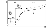
- the raw material fluid when the raw material fluid is heated and reacted, first, the raw material fluid is preheated by heat exchange between the second heat medium different from the first heat medium and the raw material fluid. Then, in this embodiment, the first heat medium and the preheated raw material fluid are heat-exchanged to heat and react the raw material fluid. Therefore, in this embodiment, the amount of heat for heating the first heat medium can be reduced as compared with the case where the raw material fluid is preheated and reacted with one heat medium. Therefore, in this embodiment, it is possible to suppress the heat energy loss of the heat source such as the exhaust gas for heating the first heat medium.
- the product of the constant pressure specific heat of the first heat medium flowing through the first heat medium line and the flow rate is the product of the constant pressure specific heat and the flow rate of the second heat medium flowing through the second heat medium line. It may be larger than the product of the constant pressure specific heat and the flow rate.
- a large amount of heat can be applied to the temperature level of the reactor, which requires a large amount of heat for the reaction of the raw material fluid, and a small amount of heat can be applied to the temperature level of the preheater, which is sufficient with a small amount of heat. Can be done. Therefore, the amount of heat required for each temperature level can be input without excess or deficiency, and heat can be effectively used according to the temperature level.
- the heat cycle medium has a heat cycle utilizing exhaust heat in which the heat cycle medium circulates, and the heat of the heat source is used to heat the heat cycle medium to heat the heat cycle medium.
- exhaust heat utilization equipment using a heat cycle medium may be provided.
- the exhaust heat utilization facility heats the first heat medium by utilizing the heat of the heat source.
- the first heat medium line guides the first heat medium heated by the heat of the heat source to the reactor.
- the portion not used for generating the reaction gas can be utilized in the heat cycle, and the output and efficiency of the plant can be improved.
- the exhaust gas generating equipment for generating exhaust gas may be further provided in the raw material fluid processing plant of the above embodiment provided with the exhaust heat utilization equipment.
- the heat source is the exhaust gas from the exhaust gas generating facility.
- the exhaust heat utilization facility heats the heat cycle medium by exchanging heat with the exhaust gas.
- the exhaust heat utilization facility is provided in a gas frame through which the exhaust gas flows and in the gas frame, and heats the first heat medium by exchanging heat between the first heat medium and the exhaust gas. It has a heat medium heater.
- the first heat medium line is connected to the first heat medium heater of the exhaust heat utilization facility, and the first heat medium heated by the heat of the exhaust gas is guided to the reactor.
- the efficiency of the plant can be improved by effectively utilizing the heat of the exhaust gas from the exhaust gas generating facility.
- the exhaust gas generating equipment may be a reaction gas utilization equipment using the reaction gas as fuel.
- a reaction gas utilization facility different from the exhaust heat utilization facility can be provided, and the exhaust heat after the reaction gas is used in the reaction gas utilization facility can be further utilized in the exhaust heat utilization facility. , The energy of the reaction gas can be recovered repeatedly, and highly efficient energy utilization becomes possible.
- the raw material reaction facility heats the first heat medium after heat exchange with the raw material fluid from the reactor to the first heat medium. It may have a first heat medium recovery line to return to the vessel.
- the first heat medium circulates between the reactor and the first heat medium heater. Therefore, in this embodiment, the temperature difference between the temperature of the first heat medium flowing out of the first heat medium heater and the temperature of the first heat medium flowing into the first heat medium heater can be minimized. Therefore, in this aspect as well, the amount of heat for heating the first heat medium can be reduced from this viewpoint as well.
- the reactor is said to have after heat exchange between the first heat medium and the raw material fluid before heat exchange with the raw material fluid. It may be configured so as not to change the phase with the first heat medium.
- the phase does not change in the process in which the first heat medium circulates between the reactor and the first heat medium heater. Therefore, in this embodiment, the amount of heat for heating the first heat medium can be reduced as compared with the case where the first heat medium undergoes a phase change.
- At least one of the first heat medium and the second heat medium is the same as the heat cycle medium. It may be a substance.
- the quality of the first heat medium or the second heat medium can be easily controlled.
- the pressure of one heat medium is the pressure of the heat cycle medium in the exhaust heat utilization heat cycle. It may be lower than the maximum pressure.
- the first heat medium can be easily supplied to the reactor or the second heat medium can be supplied to the preheater without providing a separate supply facility.
- the first heat medium can be easily supplied to the reactor or the second heat medium can be supplied to the preheater at the time of startup or when the pressure of the first heat medium drops due to seal leakage or the like.
- the reactor includes a pre-reactor that further heats and reacts the raw material fluid preheated by the preheater to generate a reaction gas, and the pre-reactor. It may have a post-reactor in which the gas from the reactor is further heated to react the raw material fluid contained in the gas from the pre-reactor.
- the pre-reactor heats the raw material fluid by exchanging heat between the first low temperature heat medium, which is a kind of the first heat medium, and the raw material fluid.
- the post-reactor is a type of the first heat medium that exchanges heat with a gas from the pre-reactor and a first high-temperature heat medium different from the first low-temperature heat medium, from the pre-reactor. Heat the gas.
- the first heat medium line includes a first low temperature heat medium line through which the first low temperature heat medium flows, and a first high temperature heat medium line through which the first high temperature heat medium flows.
- the first low temperature heat medium line is connected to the pre-reactor and guides the first low temperature heat medium to the pre-reactor.
- the first high temperature heat medium line is connected to the post-reactor and guides the first high temperature heat medium to the post-reactor.
- the reaction of the raw material fluid is executed in two stages of the reaction in the pre-reactor and the reaction in the post-reactor, the residue contained in the reaction gas flowing out from the post-reactor is executed.
- the concentration of the raw material can be reduced.
- the temperature of the first heat medium that exchanges heat with the reaction gas in the post-reactor is higher than the temperature of the first heat medium that exchanges heat with the raw material fluid in the pre-reactor, so that the reaction is performed. Heat can be used efficiently. Further, by dividing the reactor into a pre-reactor and a post-reactor and supplying a heat medium to each, the amount of heat required for each temperature level can be input in just proportion to the temperature level. Heat can be used effectively accordingly.
- the reactor further heats the raw material fluid preheated by the preheater to react. It has a pre-reactor for producing a reaction gas, and a post-reactor for further heating the gas from the pre-reactor to react the raw material fluid contained in the gas from the pre-reactor. May be good.
- the first heat medium heater exchanges heat between the first low temperature heat medium, which is a kind of the first heat medium, and the exhaust gas to heat the first low temperature heat medium.
- the first high-temperature heating medium heater is arranged in the gas frame on the upstream side of the exhaust gas flow with respect to the first low-temperature heating medium heater.
- the first heat medium line includes a first low temperature heat medium line through which the first low temperature heat medium flows, and a first high temperature heat medium line through which the first high temperature heat medium flows.
- the first low temperature heat medium line is connected to the first low temperature heat medium heater and guides the first low temperature heat medium heated by the exhaust gas to the pre-reactor.
- the first high temperature heat medium line is connected to the first high temperature heat medium heater and guides the first high temperature heat medium heated by the exhaust gas to the post-reactor.
- the reaction of the raw material fluid is executed in two stages of the reaction in the pre-reactor and the reaction in the post-reactor, the residue contained in the reaction gas flowing out from the post-reactor is executed.
- the concentration of the raw material can be reduced.
- the temperature of the first heat medium that exchanges heat with the reaction gas in the post-reactor is higher than the temperature of the first heat medium that exchanges heat with the raw material fluid in the pre-reactor, so that the reaction is performed. Heat can be used efficiently. Further, by dividing the reactor into a pre-reactor and a post-reactor and supplying a heat medium to each, the amount of heat required for each temperature level can be input in just proportion to the temperature level. Heat can be used effectively accordingly.
- the waste heat utilization facility has an exhaust heat recovery boiler that uses the heat of the exhaust gas to vaporize water.
- the exhaust heat recovery boiler has the gas frame, and both the first low-temperature heat medium and the first high-temperature heat medium may be water or steam.
- the exhaust heat utilization facility injects fuel into the exhaust gas flowing in the gas frame. It may have a burner for burning the fuel. In this case, the burner is arranged in the gas frame on the upstream side of the flow of the exhaust gas with respect to the first high-temperature heating medium heater.
- the first high-temperature heat medium heater heats the first high-temperature heat medium by exchanging heat between the combustion gas generated by the combustion of the fuel injected from the burner and the first high-temperature heat medium.
- the reaction of the raw material fluid can be promoted, and the raw material contained in the reaction gas can be promoted.
- the concentration of the fluid can be reduced.
- the exhaust heat utilization facility is contained in the exhaust gas flowing in the gas frame. It may have a burner that injects fuel and burns the fuel.
- the burner is arranged in the gas frame on the upstream side of the flow of the exhaust gas with respect to the first heat medium heater.
- the first heat medium heater heats the first heat medium by exchanging heat between the combustion gas generated by the combustion of the fuel injected from the burner and the first heat medium.
- the reaction of the raw material fluid can be promoted, and the raw material contained in the reaction gas can be promoted.
- the concentration of the fluid can be reduced.
- the constant pressure of the first low temperature heat medium flowing through the first low temperature heat medium line may be larger than the product of the constant pressure specific heat of the first high temperature heat medium flowing through the first high temperature heat medium line and the flow rate.
- a large amount of heat can be applied to the temperature level of the reactor, which requires a large amount of heat for the reaction of the raw material fluid, and a small amount of heat can be applied to the temperature level of the preheater, which is sufficient with a small amount of heat.
- the amount of heat required for each temperature level can be input without excess or deficiency, and heat can be effectively used according to the temperature level.
- the required flow rate of the high-temperature first high-temperature heat medium to be charged into the post-reactor can be reduced, high-temperature heat is saved, and heat utilization efficiency is achieved. Can be enhanced.
- the exhaust heat utilization facility is located upstream of the exhaust gas flow in the gas frame with respect to the first heat medium heater.
- the partition member may be provided to partition the first exhaust gas flow path through which a part of the exhaust gas flows and the second exhaust gas flow path through which the remaining part of the exhaust gas flows.
- the burner injects the fuel into the first exhaust gas flow path.
- the temperature of the first heat medium can be effectively raised with a small amount of reheating fuel. Burning fuel can be saved and plant efficiency can be improved.
- the raw material reaction facility includes a reaction gas line through which the reaction gas generated by the reactor flows and the reaction gas line. It may have a residual raw material removing device for removing the residual raw material which is a raw material fluid contained in the reaction gas flowing through the above and discharging the treated reaction gas which is the reaction gas from which the residual raw material has been removed.
- the exhaust gas generating facility utilizes the processed reaction gas which is a part of the reaction gas.
- the amount of residual raw material in the reaction gas sent to the reaction gas utilization facility can be reduced.
- the second heat medium may be the reaction gas
- the second heat medium line may be the reaction gas line
- the preheater exchanges heat between the raw material fluid and the reaction gas as the second heat medium, and while the raw material fluid is heated, the reaction gas is cooled. Therefore, in this embodiment, the low temperature reaction gas can be sent to the residual raw material removing device. Further, the plant efficiency can be improved by effectively utilizing the exhaust heat of the reaction gas cooling.
- the preheater is a vaporizer that heats and vaporizes the liquid raw material fluid and gas heating that heats the gas raw material fluid from the vaporizer.
- the vaporizer is a heat exchanger that heats the liquid raw material fluid by exchanging heat between the vaporization second heat medium, which is a kind of the second heat medium, and the liquid raw material fluid.
- the gas heater is a kind of the second heat medium and is different from the second heat medium for vaporization, and heat exchanges between the second heat medium for gas heating and the raw material fluid of the gas to exchange the heat of the gas.
- a heat exchanger that heats the raw material fluid.
- different heat media are used for vaporization of the raw material fluid that requires a large amount of heat and heating with a gas that requires a small amount of heat.
- the amount of heat required for each temperature level can be input in just proportion to the vaporization of the raw material fluid and the heating with a gas, and the heat is effectively used according to the temperature level. be able to.
- the product of the constant pressure specific heat and the flow rate of the second heat medium for vaporization flowing in the vaporizer flows in the gas heater. It may be larger than the product of the constant pressure specific heat and the flow rate of the second heat medium for gas heating.
- a large amount of heat can be applied to the temperature level of the vaporizer, which requires a large amount of heat for vaporizing the raw material fluid, and a sufficient amount of heat can be applied to the temperature level of the gas heater with a small amount of heat. Can be done. Therefore, the amount of heat required for each temperature level can be input without excess or deficiency, heat can be effectively used according to the temperature level, and heat utilization efficiency can be improved.
- the vaporizer accepts the second heat medium for vaporization of the gas, and the second heat medium for vaporization of the gas and the liquid. It may have the ability to cool and condense the second heat medium for vaporization of the gas by exchanging heat with the raw material fluid of the gas.
- the heat source medium can be vaporized at a constant temperature by using the second heat medium for vaporization that condenses at a constant temperature as a heat source. Therefore, in this embodiment, the heat of a relatively low constant temperature can be effectively utilized to vaporize the raw material fluid, and the heat utilization efficiency can be improved.
- the vaporizer is a liquid phase preheater for raising the temperature of the raw material fluid of the liquid as it is, and a liquid phase preheater. It may have a phase change preheater that heats and vaporizes the liquid raw material fluid.
- the liquid phase preheater heats the liquid raw material fluid by exchanging heat between the liquid phase preheating second heat medium, which is a kind of the vaporization second heat medium, and the liquid raw material fluid. It is a heat exchanger.
- the phase change preheater is a kind of the second heat medium for vaporization and is different from the second heat medium for liquid phase preheating, and the second heat medium for phase change preheating and the raw material of the liquid from the liquid phase preheater. It is a heat exchanger that exchanges heat with a fluid to heat the raw material fluid of the liquid.
- the vaporizer is divided into a portion for vaporizing the raw material fluid in the liquid phase and a portion for preheating the raw material fluid in the liquid phase. Then, different heat media are used for vaporization of the raw material fluid that requires a large amount of heat and for heating with the liquid phase having a small amount of heat required. Therefore, in this embodiment, the amount of heat required for each temperature level can be input in just proportion to the vaporization of the raw material fluid and the heating in the liquid phase, which is effective according to the temperature level. The heat can be utilized.
- the product of the constant pressure specific heat and the flow rate of the second heat medium for phase change preheating flowing in the phase change preheater is It may be larger than the product of the constant pressure specific heat and the flow rate of the second heat medium for liquid phase preheating flowing in the liquid phase preheater.
- a large amount of heat can be applied to the temperature level of the phase change preheater that requires a large amount of heat for vaporization of the raw material fluid, and a small amount of heat can be applied to the temperature level of the liquid phase preheater that is sufficient with a small amount of heat. Can be thrown in. Therefore, the amount of heat required for each temperature level can be input without excess or deficiency, heat can be effectively used according to the temperature level, and heat utilization efficiency can be improved.
- the phase change preheater receives the second heat medium for phase change preheating of the gas and the phase change of the gas. It may have the ability to exchange heat between the second heat medium for preheating and the raw material fluid of the liquid from the liquid phase preheater to cool and condense the second heat medium for phase change preheating of the gas.
- the raw material fluid can be vaporized at a constant temperature using a second heat medium for phase change preheating that condenses at a constant temperature as a heat source. Therefore, in this embodiment, the heat of a relatively low constant temperature can be effectively utilized to vaporize the raw material fluid, and the heat utilization efficiency can be improved.
- the raw material fluid processing plant of any of the above embodiments having a heat cycle utilizing exhaust heat may be provided with one or more heat cycles.
- the one or more heat cycles include the exhaust heat utilization heat cycle in which the heat cycle medium circulates.
- the raw material reaction facility has a second heat medium recovery line through which the second heat medium flows.
- the second heat medium is at least a part of the first heat cycle medium flowing in the first heat cycle of the one or more heat cycles.
- the second heat medium line guides the first heat cycle medium flowing through the first part of the first heat cycle to the preheater as the second heat medium.
- the second heat medium recovery line has the raw material fluid in the second part through which the first heat cycle medium having a temperature lower than that of the first heat cycle medium flowing in the first part during the first heat cycle flows.
- the first heat cycle medium cooled by heat exchange is derived.
- the first heat cycle medium flowing in the first heat cycle can be used for preheating the raw material fluid.
- the first heat cycle may be the waste heat utilization heat cycle.
- the first heat cycle medium is water or steam as the heat cycle medium that circulates in the waste heat utilization heat cycle.
- the exhaust heat utilization equipment is in the gas frame and is the first heat medium.
- a second heat medium heater that is arranged downstream of the exhaust gas flow and heats at least a part of the heat cycle medium by exchanging heat with at least a part of the heat cycle medium and the exhaust gas. May have.
- the raw material reaction facility has a second heat medium recovery line through which the second heat medium flows. The second heat medium line guides the preheater using at least a part of the heat cycle medium heated by the second heat medium heater as the second heat medium.
- the second heat medium recovery line is cooled by the preheater to a portion of the second heat medium heater in which the heat cycle medium having a temperature lower than that of the heat cycle medium flows in the waste heat utilization heat cycle.
- the heat cycle medium after the heat cycle is derived.
- the Brayton cycle in which the working medium of gas circulates may be provided in the processing plant for the raw material fluid of any of the above embodiments.
- the Brayton cycle includes a medium compressor that compresses the working medium, a medium heater that heats the working medium compressed by the medium compressor, and a medium turbine that is driven by the working medium heated by the medium heater.
- the raw material reaction facility has a second heat medium recovery line through which the second heat medium flows.
- the medium cooler constitutes at least a part of the preheater.
- the second heat medium line guides the working medium exhausted from the medium turbine to the medium cooler as the second heat medium.
- the second heat medium recovery line guides the working medium cooled by heat exchange with the raw material fluid to the medium compressor as the second heat medium in the medium cooler.
- the medium cooler that forms a part of the preheater cools the working medium by exchanging heat between the raw material fluid and the working medium. Therefore, in this embodiment, the Brayton cycle can be operated by utilizing the heat of the raw material fluid, and the output of the plant can be increased.
- the preheater is more than the first heat medium heater in the gas frame. It may be a heat exchanger that is arranged on the downstream side of the flow of the exhaust gas and heats the raw material fluid by exchanging heat between the raw material fluid and the exhaust gas as the second heat medium.
- the second heat medium line is configured to have a part of the gas frame.
- the heat of the low-temperature exhaust gas is used for preheating the raw material fluid. Therefore, in this embodiment, the heat of the low-temperature exhaust gas can be effectively utilized.
- the exhaust heat utilization equipment is arranged in the gas frame, and the heat cycle medium of the liquid phase and the exhaust gas.
- the preheater is arranged in the gas frame on the downstream side of the evaporator on the most downstream side of the one or more evaporators. At least one of the one or more evaporators is arranged between the first heat medium heater and the preheater in the flow direction of the exhaust gas.
- the raw material fluid processing plant of the embodiment having the residual raw material removing device may include a heat cycle in which the third heat medium flows and the heated third heat medium is used.
- the raw material reaction facility includes a third heat medium line and a third heat medium recovery line connected to the heat cycle, and a reaction gas cooler for cooling the reaction gas.
- the reaction gas cooler is provided in the reaction gas line and exchanges heat with the third heat medium for the reaction gas flowing through the reaction gas line to cool the reaction gas while cooling the third heat medium.
- the third heat medium line guides at least a part of the third heat medium before heating from the heat cycle to the reaction gas cooler.
- the third heat medium recovery line guides the third heat medium after being heated by the reaction gas cooler to the heat cycle.
- the residual raw material removing device removes the residual raw material from the reaction gas cooled by the reaction gas cooler.
- the cooled reaction gas RG can be sent to the residual raw material removing device. Further, in this embodiment, the exhaust heat of the reaction gas cooling can be effectively utilized to send the third heat medium heated in the heat cycle, and the efficiency of the plant can be improved.
- the exhaust gas generating equipment may have a gas turbine.
- the gas turbine includes an air compressor that compresses air to generate combustion air, a combustor that uses the processed reaction gas as fuel and burns it in the combustion air to generate combustion gas, and the combustion gas. It has a turbine that is driven by the engine and discharges the combustion gas as the exhaust gas.
- the thermal cycle is a gas turbine cycle including the gas turbine included in the exhaust gas generating facility.
- the third heat medium line guides the processed reaction gas from the residual raw material removing device to the reaction gas cooler as the third heat medium.
- the third heat medium recovery line guides the processed gas after being heated by the reaction gas cooler to the combustor.
- the reaction gas cooler exchanges heat between the reaction gas and the processed reaction gas as fuel to cool the reaction gas and heat the fuel. Therefore, in this embodiment, the cooled reaction gas can be sent to the residual raw material removing device, and the preheated fuel can be sent to the combustor, so that the efficiency of the plant can be improved. Further, by removing the residual raw material remaining in the reaction gas with the residual raw material removing device, the concentration of the residual raw material of the fuel sent to the fuel combustor can be reduced, and the air pollutant caused by the residual raw material in the fuel can be reduced. Can be reduced.
- the exhaust gas generating equipment may have a gas turbine.
- the gas turbine includes an air compressor that compresses air to generate combustion air, a combustor that burns fuel from the processed reaction gas in the combustion air to generate combustion gas, and the combustion gas. It has a turbine that is driven by a turbine and discharges the combustion gas as the exhaust gas.
- the thermal cycle is a gas turbine cycle including the gas turbine included in the exhaust gas generating facility.
- the third heat medium line guides the combustion air from the air compressor to the reaction gas cooler as the third heat medium.
- the third heat medium recovery line guides the combustion air after being heated by the reaction gas cooler to the combustor.
- the reaction gas cooler exchanges heat between the reaction gas and the combustion air to cool the reaction gas and heat the combustion air. Therefore, in this embodiment, the cooled reaction gas can be sent to the residual raw material removing device, and the preheated combustion air can be sent to the combustor.
- the exhaust gas generating facility may have a gas turbine driven by using the processed reaction gas as fuel.
- the exhaust heat utilization equipment includes an exhaust heat recovery boiler that evaporates water using the heat of the exhaust gas exhausted from the gas turbine, a steam turbine driven by steam from the exhaust heat recovery boiler, and the steam turbine. It has a condenser that returns the steam exhausted from the steam to water, and a water supply pump that sends the water in the condenser to the exhaust heat recovery steam generator.
- the heat cycle is a Rankine cycle including the exhaust heat recovery boiler, the steam turbine, the condenser, and the water supply pump.
- the third heat medium line guides at least a part of water or steam flowing through the first part of the Rankine cycle to the reaction gas cooler as the third heat medium.
- the third heat medium recovery line is after being heated by the reaction gas cooler in the second part through which water or steam having a temperature higher than that of water or steam flowing through the first part flows in the Rankine cycle. Guide water or steam.
- the reaction gas cooler exchanges heat between the reaction gas and the water or steam flowing through the Rankine cycle to cool the reaction gas while heating the water or steam. Therefore, in this embodiment, the cooled reaction gas can be sent to the residual raw material removing device, and the heated water or steam can be returned to the Rankine cycle, so that the thermal efficiency of the Rankine cycle can be improved.
- the raw material fluid processing plant of the above aspect which comprises the thermal cycle utilizing the third heat medium, may include a low boiling point medium Rankine cycle in which a low boiling point medium having a boiling point lower than that of water circulates.
- the low-boiling medium Rankin cycle heats a medium booster that raises the pressure of the low-boiling medium of the liquid phase and the low-boiling medium of the liquid phase that has been boosted by the medium booster to form a low-boiling medium of the gas phase.
- the thermal cycle is the low boiling point medium Rankine cycle.
- the reaction gas cooler forms the medium heater.
- the third heat medium line guides the low boiling point medium of the liquid phase boosted by the medium booster to the reaction gas cooler forming the medium heater using the third heat medium.
- the third heat medium recovery line guides the low boiling point medium of the gas phase from the reaction gas cooler to the medium turbine.
- the reaction gas cooler forming the medium heater of the low boiling point medium Rankine cycle exchanges heat between the reaction gas and the low boiling point medium to cool the reaction gas and heat the low boiling point medium. Therefore, in this embodiment, the low boiling point medium Rankincycle can be operated by utilizing the heat of the reaction gas, and the output of the plant can be increased.
- the Brayton cycle in which the working medium of the gas circulates may be provided in the processing plant for the raw material fluid of the above embodiment, which comprises the heat cycle utilizing the third heat medium.
- the Brayton cycle includes a medium compressor that compresses the working medium, a medium heater that heats the working medium compressed by the medium compressor, and a medium turbine that is driven by the working medium heated by the medium heater.
- the thermal cycle is the Brayton cycle.
- the reaction gas cooler forms the medium heater.
- the third heat medium line guides the working medium from the medium compressor to the reaction gas cooler forming the medium heater, using the working medium as the third heat medium.
- the third heat medium recovery line guides the working medium from the reaction gas cooler to the medium turbine.
- the reaction gas cooler forming the medium heater of the Brayton cycle exchanges heat between the reaction gas and the working medium to cool the reaction gas and heat the working medium. Therefore, in this embodiment, the Brayton cycle can be operated by utilizing the heat of the reaction gas, and the output of the plant can be increased.
- the raw material reaction facility puts an oxidant that causes an oxidation reaction of the raw material fluid into the raw material fluid after passing through the preheater. It may have a device.
- a part of the raw material fluid oxidizes with the oxidizing agent to generate heat.
- the temperature of the raw material fluid rises, the reaction of the raw material fluid is promoted, and the concentration of the raw material fluid in the reaction gas can be lowered.
- the reactor includes a pre-reactor that further heats and reacts the raw material fluid preheated by the preheater to generate a reaction gas. It may have a post-reactor for further reacting the raw material fluid contained in the gas from the pre-reactor.
- the oxidant charging device is the raw material fluid after passing through the preheater and before flowing out from the pre-reactor, and the gas that has passed through the pre-reactor and is from the post-reactor. The oxidizing agent is charged into at least one of the gases before the outflow.
- the oxidant charging device may have a compressor that compresses air to generate compressed air.
- the oxidizing agent charging device uses the compressed air as the oxidizing agent and charges the compressed air into the raw material fluid after passing through the preheater.
- the gas turbine may be further provided in the raw material fluid processing plant of the above embodiment in which the oxidizing agent charging device has the compressor.
- the gas turbine includes an air compressor that compresses air to generate combustion air, a combustor that burns fuel in the combustion air to generate combustion gas, and the combustion gas driven by the combustion gas. It has a turbine that discharges gas as exhaust gas.
- At least a part of the compressor of the oxidant charging device is the air compressor of the gas turbine.
- the oxidizing agent charging device uses a part of the combustion air from the air compressor as the oxidizing agent and charges it into the raw material fluid after passing through the preheater.
- the processing plant for the raw material fluid of another aspect according to the invention for achieving the above object includes a raw material reaction facility that heats and reacts a raw material fluid to generate a reaction gas, and a heat cycle in which a third heat medium flows and the heated third heat medium is used.
- the raw material reaction facility is connected to a reactor that heats and reacts the raw material fluid to generate a reaction gas, a reaction gas line through which the reaction gas generated by the reactor flows, and the thermal cycle. It has a third heat medium line, a third heat medium recovery line, and a reaction gas cooler for cooling the reaction gas.
- the reaction gas cooler is provided in the reaction gas line and exchanges heat with the third heat medium for the reaction gas flowing through the reaction gas line to cool the reaction gas while cooling the third heat medium.
- the third heat medium line guides at least a part of the third heat medium before heating from the heat cycle to the reaction gas cooler.
- the third heat medium recovery line guides the third heat medium after being heated by the reaction gas cooler to the heat cycle.
- the third heat medium can be heated by the exhaust heat of the reaction gas cooler and used in the heat cycle, the exhaust heat can be effectively utilized and the efficiency of the plant can be improved.
- the reaction gas cooler has the ability to heat the third heat medium to a temperature higher than the temperature of the raw material fluid at the inlet of the raw material fluid in the reactor. You may have.
- the temperature of the medium of the thermal cycle to the temperature level of the reactor can be utilized by utilizing the exhaust heat of the reaction gas cooler.
- the efficiency of the thermal cycle is increased, and the efficiency of the plant is further increased.
- the raw material fluid processing plant of the other aspect may further include an exhaust gas generating facility that burns the reaction gas generated by the raw material reaction facility to generate an exhaust gas.
- the generated reaction gas is effectively utilized and the efficiency of the plant is improved.
- the exhaust gas generating equipment may have a gas turbine.
- the gas turbine is driven by an air compressor that compresses air to generate combustion air, a combustor that uses the reaction gas as fuel and burns it in the combustion air to generate combustion gas, and the combustion gas. It has a turbine that discharges the combustion gas as an exhaust gas.
- the exhaust heat utilization facility is from an exhaust heat recovery boiler that evaporates water by using the heat of exhaust gas as the heat source and an exhaust heat recovery boiler.
- a steam turbine driven by steam, a condenser that returns the steam exhausted from the steam turbine to water, a water supply line that guides the water in the condenser to the exhaust heat recovery boiler, and a water supply line are provided. You may have a water pump that is running.
- the exhaust heat recovery boiler has the gas frame through which the exhaust gas flows.
- the exhaust heat utilization facility heats the water by exchanging heat between the water flowing through the water supply line and the steam extracted from the steam turbine. It may have a preheater.
- the water flowing through the water supply line can be heated by the water supply preheater. Therefore, in this embodiment, the temperature of the supply water flowing into the exhaust heat recovery boiler can be increased.
- the temperature of the supply water flowing into the exhaust heat recovery boiler becomes high, the amount of heat exchange between water or steam and the exhaust gas can be reduced in each economizer, each evaporator, and each heater in the exhaust heat recovery boiler. Therefore, it is preferable to adopt this embodiment when the amount of heat for heating the raw material fluid is small.
- the raw material fluid may be ammonia.
- the reactor heats the ammonia and causes a thermal decomposition reaction to generate a reaction gas containing nitrogen and hydrogen.
- the raw material reaction execution step of generating the reaction gas by heating and reacting the raw material fluid is executed.
- the raw material reaction step includes a raw material preheating step and a reaction execution step.
- the second heat medium and the raw material fluid are heat-exchanged to heat the raw material fluid.
- the reaction step the raw material fluid heated in the raw material preheating step is heat-exchanged with a first heat medium different from the second heat medium, and the raw material fluid is further heated and reacted to generate a reaction gas. Generate.
- the method for treating the raw material fluid of another aspect according to the invention for achieving the above object is A raw material reaction step of heating and reacting a raw material fluid to generate a reaction gas, and a heat cycle execution step of flowing a third heat medium and utilizing the heated third heat medium are executed.
- the raw material reaction step includes a reaction execution step of heating and reacting the raw material fluid to generate a reaction gas, and a reaction gas cooling step of cooling the reaction gas generated in the reaction execution step.
- the reaction gas cooling step at least a part of the third heat medium before being heated and the reaction gas are heat-exchanged to cool the reaction gas while heating the third heat medium.
- the third heat medium heated in the reaction gas cooling step is used.
- the thermal energy loss of a heat source such as exhaust gas can be suppressed and the thermal efficiency of the plant can be improved.
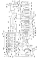
- FIG. 1 It is a system diagram of the processing plant of the raw material fluid in the 1st Embodiment which concerns on this invention. It is a flowchart which shows the operation of the gas utilization blunt in 1st Embodiment which concerns on this invention. It is a TQ diagram of ammonia and a heat source in a reference example. It is a TQ diagram of ammonia and a heat source in the first embodiment. It is a system diagram of the processing plant of the raw material fluid in the 2nd Embodiment which concerns on this invention. It is a system diagram of the processing plant of the raw material fluid in the 3rd Embodiment which concerns on this invention. It is a TQ diagram of ammonia and a heat source in a third embodiment.
- FIG. 1 It is a system diagram of the processing plant of the raw material fluid in the 1st Embodiment which concerns on this invention. It is a flowchart which shows the operation of the gas utilization blunt in 1st Embodiment which concerns on this invention.
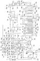
- FIG. 5 is a TQ diagram of ammonia and a heat source in a modified example of the third embodiment. It is a system diagram of the processing plant of the raw material fluid in 4th Embodiment which concerns on this invention. It is a TQ diagram of ammonia and a heat source in a fourth embodiment. It is a system diagram of the processing plant of a raw material fluid in 5th Embodiment which concerns on this invention. It is a system diagram of the processing plant of the raw material fluid in the sixth embodiment which concerns on this invention. It is a system diagram of the processing plant of the raw material fluid in the 7th Embodiment which concerns on this invention. It is a system diagram of the processing plant of a raw material fluid in 8th Embodiment which concerns on this invention.
- the raw material fluid processing plant of the present embodiment includes a raw material reaction facility 40 that reacts the raw material fluid NH to generate a reaction gas RG, and a reaction gas utilization facility 10 that uses the reaction gas RG.
- the exhaust heat utilization facility 20 that utilizes the heat of the exhaust gas EG from the reaction gas utilization facility 10 is provided.
- the raw material fluid NH of this embodiment is ammonia.
- the raw material reaction facility 40 thermally decomposes ammonia, which is the raw material fluid NH, to generate a reaction gas RG containing hydrogen and nitrogen.
- the reaction gas utilization facility 10 is a gas turbine facility including a gas turbine 11 that uses the reaction gas RG as fuel.
- the reaction gas utilization facility 10 in this embodiment and the reaction gas utilization facility in each of the following embodiments are also exhaust gas generation facilities that generate exhaust gas EG.
- the exhaust heat utilization facility 20 includes an exhaust heat recovery boiler 21 that generates steam by utilizing the heat of the exhaust gas EG exhausted from the gas turbine 11, and steam turbines 31, 32, 33, etc. that are driven by the steam. Have.
- the raw material reaction facility 40 includes a raw material reaction device 41 and a residual raw material removing device 130.
- the raw material reactor 41 thermally decomposes liquid ammonia NH, which is a raw material fluid, to generate a reaction gas RG containing hydrogen, nitrogen, and residual ammonia.
- the residual raw material removing device 130 removes the residual raw material (residual ammonia) from the reaction gas RG, and discharges the treated reaction gas RGp which is the reaction gas RG from which the residual raw material has been removed.
- the raw material reactor 41 includes an ammonia supply line 42 through which liquid ammonia NH or gaseous ammonia NHg from the ammonia tank T flows, a raw material ammonia pump 43, preheaters 44a and 44b, a reactor 45, and a reaction gas cooler 46. , A reaction gas line 47, a first heat medium line 51, a first heat medium recovery line 52, and a first heat medium booster 53.
- Liquid ammonia NH is stored in the ammonia tank T.
- Liquid ammonia NH is produced, for example, from hydrogen as a raw material.
- This hydrogen is, for example, hydrogen obtained by electrolyzing water using electricity generated by renewable energy such as wind power or sunlight, or hydrogen obtained by steam reforming natural gas. is there. Hydrogen is not as easy to transport and store as liquefied natural gas. Therefore, the hydrogen obtained as described above is used to produce liquid ammonia NH that can be easily transported and stored, and the liquid ammonia NH is stored in the ammonia tank T
- the ammonia supply line 42 has a first ammonia supply line 42a, a second ammonia supply line 42b, and a third ammonia supply line 42c.
- One end of the first ammonia supply line 42a is connected to the ammonia tank T.
- the preheaters 44a and 44b include a first preheater 44a and a second preheater 44b.
- the other end of the first ammonia supply line 42a is connected to the ammonia inlet of the first preheater 44a.
- the first preheater 44a is a heat exchanger.
- the first preheater 44a exchanges heat between the liquid ammonia NH and the second heat medium to heat the liquid ammonia NH to produce gaseous ammonia NHg, while cooling the second heat medium.
- One end of the second ammonia supply line 42b is connected to the ammonia outlet of the first preheater 44a, and the other end of the second ammonia supply line 42b is connected to the ammonia inlet of the second preheater 44b.
- the second preheater 44b is a heat exchanger.
- the second preheater 44b exchanges heat between the gaseous ammonia NHg and the second heat medium to heat the gaseous ammonia NHg while cooling the second heat medium.
- One end of the third ammonia supply line 42c is connected to the ammonia outlet of the second preheater 44b, and the other end of the third ammonia supply line 42c is connected to the ammonia inlet of the reactor 45.
- the first heat medium line 51 is connected to the medium inlet of the reactor 45.
- a first heat medium recovery line 52 is connected to the medium outlet of the reactor 45.
- the first heat medium booster 53 is provided on the first heat medium recovery line 52.
- the reactor 45 is a heat exchanger.
- a catalyst that promotes the thermal decomposition reaction of the raw material fluid is arranged in the region through which the raw material fluid passes in the reactor 45.
- the raw material fluid is ammonia, as described above.
- the catalyst is not arranged in the preheaters 44a and 44b, and the catalyst is arranged in the reactor 45.
- the catalyst is arranged only in the region where the temperature is sufficiently high for the reaction of the raw material fluid to proceed actively, and the catalyst is not arranged in the region where the temperature is low where the reaction does not proceed even if the catalyst is arranged.
- the reaction can be effectively promoted with a small amount of catalyst, and the cost of the catalyst can be reduced.
- the reactor 45 the raw material fluid undergoes an endothermic reaction. According to this embodiment, the heat required for the endothermic reaction can be efficiently supplied.
- the reactor 45 exchanges heat between the gaseous ammonia NHg heated by the second preheater 44b and the first heat medium from the first heat medium line 51 to further heat the gaseous ammonia NHg, while the first heat. Cool the medium.
- the cooled first heat medium flows into the first heat medium recovery line 52.
- the gaseous ammonia NHg heated in the reactor 45 becomes a reaction gas RG containing hydrogen, nitrogen and residual ammonia by a thermal decomposition reaction.
- the reaction gas line 47 has a first reaction gas line 47a, a second reaction gas line 47b, and a third reaction gas line 47c. One end of the first reaction gas line 47a is connected to the reaction gas outlet of the reactor 45. The other end of the first reaction gas line 47a is connected to the second heat medium inlet of the second preheater 44b.
- reaction gas line 47b is connected to the second heat medium outlet of the second preheater 44b, and the other end of the second reaction gas line 47b is connected to the second heat medium inlet of the first preheater 44a.
- One end of the third reaction gas line 47c is connected to the outlet of the second heat medium of the first preheater 44a, and the other end of the third reaction gas line 47c is connected to the residual raw material removing device 130. Therefore, in the present embodiment, the reaction gas RG is the second heat medium. Further, in the present embodiment, the second heat medium line that guides the reaction gas RG, which is the second heat medium, to the first preheater 44a and the second preheater 44b is the reaction gas line 47.
- the reaction gas cooler 46 is provided in the third reaction gas line 47c. The reaction gas cooler 46 cools the reaction gas RG flowing through the third reaction gas line 47c.
- the residual raw material removing device 130 includes an absorption tower 131, a regeneration tower 132, an ammonia water line 133, a water line 134, a water supply pump 135, a heat exchanger 136, a water circulation line 137, a condenser 138, and the like. It has a reboiler 139, a recovered ammonia line 140, and a recovered ammonia booster 141.
- the other end of the reaction gas line 47 is connected to the lower part of the absorption tower 131.
- One end of the water line 134 is connected to the upper part of the absorption tower 131. Water from the water line 134 is sprayed into the absorption tower 131, and the reaction gas RG from the reaction gas line 47 flows into the absorption tower 131. In the absorption tower 131, water and the reaction gas RG come into contact with each other, and the residual ammonia in the reaction gas RG dissolves in water. As a result, the ammonia water, which is the water in which the residual ammonia is dissolved, collects in the lower part of the absorption tower 131.
- the treated reaction gas RGp which is the reaction gas RG from which the residual ammonia has been removed, rises in the absorption tower 131.
- the concentration of ammonia NHg in the gas phase dissolved in water increases as the temperature inside the absorption tower 131 decreases. Therefore, in the present embodiment, the reaction gas RG flowing out of the reactor 45 is sequentially cooled by the second preheater 44b, the first preheater 44a, and the reaction gas cooler 46, and then guided into the absorption tower 131. There is.
- the ammonia water line 133 connects the bottom of the absorption tower 131 and the top of the regeneration tower 132.
- the ammonia water accumulated in the absorption tower 131 is guided into the regeneration tower 132 via the ammonia water line 133.
- One end of the water circulation line 137 is connected to the bottom of the regeneration tower 132, and the other end of the water circulation line 137 is connected to the lower part (above the bottom) of the regeneration tower 132.
- a reboiler 139 is provided in the water circulation line 137. The reboiler 139 exchanges heat between the steam from the exhaust heat utilization facility 20 and the water from the water circulation line 137, cools the steam and condenses it into heated water, while heating the water from the water circulation line 137.
- This steam flows into the regeneration tower 132 via the water circulation line 137.
- the ammonia water is heated by steam, and the ammonia in the ammonia water is separated and distilled as gaseous ammonia NHg.
- the water in the ammonia water collects in the regeneration tower 132.
- a part of the water collected in the regeneration tower 132 flows into the regeneration tower 132 as steam via the water circulation line 137 and the reboiler 139.
- the other end of the water line 134 described above is connected to the water circulation line 137 or the reboiler 139. Therefore, the rest of the water accumulated in the regeneration tower 132 is sent to the absorption tower 131 via the water line 134.
- the water supply pump 135 is provided in this water supply line.
- the heat exchanger 136 heats the ammonia water while cooling the water by exchanging heat between the water flowing through the water line 134 and the ammonia water flowing through the ammonia water line 133.
- One end of the recovered ammonia line 140 is connected to the top of the regeneration tower 132, and the other end of the recovered ammonia line 140 is connected to the second ammonia supply line 42b through which gaseous ammonia NHg flows.
- the recovered ammonia line 140 is provided with a condenser 138 and a recovered ammonia booster 141. Gas containing gaseous ammonia NHg and water flows into the condenser 138 from the regeneration tower 132. The condenser 138 condenses the water contained in the gas from the regeneration tower 132, and returns this water to the regeneration tower 132.
- the gas from which water has been removed by the condenser 138 and the concentration of gaseous ammonia NHg has increased is boosted by the recovery ammonia booster 141, and then passes through the recovery ammonia line 140 and the second ammonia supply line 42b, and is second. It flows into the preheater 44b.
- the reaction gas utilization facility 10 has a fuel line 12 and a fuel preheater 13 in addition to the gas turbine 11 described above.
- the gas turbine 11 includes an air compressor 11a that compresses air to generate combustion air, a combustor 11c that burns fuel in the combustion air to generate combustion gas, and a turbine 11d that is driven by the combustion gas.
- the air compressor 11a has a compressor rotor and a compressor casing that covers the compressor rotor.
- the turbine 11d includes a turbine rotor and a turbine casing that covers the turbine rotor.
- the compressor rotor and the turbine rotor are connected to each other to form a gas turbine rotor.
- a generator is connected to the end of the gas turbine rotor.
- One end of the fuel line 12 is connected to the top of the absorption tower 131, and the other end of the fuel line 12 is connected to the combustor 11c. Therefore, the processed reaction gas RGp generated in the absorption tower 131 is sent to the combustor 11c as fuel.
- the fuel line 12 is provided with a fuel preheater 13.
- the fuel preheater 13 heats the treated reaction gas RGp as a fuel.
- the treated reaction gas RGp heated by the fuel preheater 13 flows into the combustor 11c.
- the reaction gas utilization facility 10 described above has a gas turbine cycle which is a kind of thermal cycle.
- This gas turbine cycle includes a fuel line 12, a fuel preheater 13, and a gas turbine 11.
- the exhaust heat utilization facility 20 includes a condenser 34, a water supply line 35, a water supply pump 36, and a chimney 39, in addition to the exhaust heat recovery boiler 21 and steam turbines 31, 32, 33 described above.
- the exhaust heat utilization facility 20 of the present embodiment has a low pressure steam turbine 31, a medium pressure steam turbine 32, and a high pressure steam turbine 33 as steam turbines 31, 32, 33.
- Each of the steam turbines 31, 32, 33 has a turbine rotor and a turbine casing that covers the turbine rotor.
- the turbine rotors of each steam turbine 31, 32, 33 are connected to each other to form one steam turbine rotor.
- a generator is connected to the end of the steam turbine rotor.
- a condenser 34 is connected to the low-pressure steam turbine 31.
- the condenser 34 returns the steam exhausted from the low-pressure steam turbine 31 to water.
- the water supply line 35 connects the condenser 34 and the exhaust heat recovery boiler 21.
- the water supply pump 36 is provided in the water supply line 35. The water supply pump 36 sends the water in the condenser 34 to the exhaust heat recovery boiler 21 via the water supply line 35.
- the exhaust heat recovery boiler 21 includes a gas frame 22, a first low-pressure economizer 23a, a second low-pressure economizer 23b, a low-pressure evaporator 23c, a low-pressure superheater 23f, a medium-pressure economizer 24a, and the like.
- Exhaust gas EG exhausted from the gas turbine 11 flows in the gas frame 22.
- the gas frame 22 has an inlet and an outlet.
- the exhaust port of the turbine 11d is connected to the inlet of the gas frame 22.
- a chimney 39 is connected to the outlet of the gas frame 22.
- the exhaust gas EG flows through the gas frame 22 from the inlet to the outlet.
- the side where the entrance exists with respect to the exit is the upstream side, and the opposite side is the downstream side.
- the first high-pressure economizer 25a, a part of the low-pressure economizer 23c, the second low-pressure economizer 23b, and the first low-pressure economizer 23a are arranged in the above order from the upstream side to the downstream side in the gas frame 22. It is located inside.
- the medium-pressure economizer 24a is arranged at substantially the same position as the first high-pressure economizer 25a in the flow direction of the exhaust gas EG.
- a water supply line 35 is connected to the first low pressure economizer 23a.
- the first low-pressure economizer 23a heats the water by exchanging heat between the water from the water supply line 35 and the exhaust gas EG.
- the second low-pressure economizer 23b exchanges heat between the water from the first low-pressure economizer 23a and the exhaust gas EG, and further heats this water to obtain low-pressure heated water.
- the low-pressure evaporator 23c exchanges heat between the low-pressure heated water and the exhaust gas EG, and heats the low-pressure heated water into steam.
- the low-pressure superheater 23f exchanges heat between the steam from the low-pressure evaporator 23c and the exhaust gas EG, and heats this steam to obtain low-pressure steam.
- One end of the low pressure steam line 88 is connected to the outlet of the low pressure superheater 23f.
- the other end of the low pressure steam line 88 is connected to the inlet of the low pressure steam turbine 31.
- the medium pressure pump 24p boosts the low pressure heated water.
- the medium-pressure economizer 24a exchanges heat between the heated water boosted by the medium-pressure pump 24p and the exhaust gas EG, and further heats the heated water to obtain medium-pressure heated water.
- An inlet of the medium pressure evaporator 24b is connected to the outlet of the medium pressure economizer 24a, and a medium pressure heating water line 77 is connected to the outlet.
- the medium pressure heated water line 77 is connected to the medium inlet of the fuel preheater 13 described above.
- the fuel preheater 13 heats the treated reaction gas RGp by exchanging heat between the medium pressure heated water from the medium pressure heated water line 77 and the treated reaction gas RGp as fuel, while heating the medium pressure heated water. Cooling.
- a heated water recovery line 78 is connected to the medium outlet of the fuel preheater 13.
- the heated water recovery line 78 is connected to the water supply line 35.
- the medium pressure evaporator 24b exchanges heat between the medium pressure heated water and the exhaust gas EG to heat the medium pressure heated water into medium pressure steam.
- a medium line 71 for the first reboiler is connected to the outlet of the medium pressure evaporator 24b.
- the medium line 71 for the first reboiler is connected to the medium inlet of the reboiler 139 described above.
- a media recovery line 73 for the reboiler is connected to the medium outlet of the reboiler 139.
- the reboiler medium recovery line 73 is connected to the inlet of the medium pressure economizer 24a.
- the reboiler medium recovery line 73 is provided with a reboiler medium booster 74.
- the high pressure pump 25p boosts the low pressure heating water.
- the first high-pressure economizer 25a exchanges heat between the heated water boosted by the high-pressure pump 25p and the exhaust gas EG to further heat the heated water.
- the second high-pressure economizer 25b exchanges heat between the heated water heated by the first high-pressure economizer 25a and the exhaust gas EG to further heat the heated water.
- the high-pressure evaporator 25c exchanges heat between the heated water heated by the second high-pressure economizer 25b and the exhaust gas EG, and heats the heated water into steam.
- the high-pressure superheater 25d exchanges heat between the steam and the exhaust gas EG, and further superheats the steam to obtain high-pressure steam.
- One end of the high pressure steam line 83 is connected to the outlet of the high pressure superheater 25d.
- the other end of the high pressure steam line 83 is connected to the inlet of the high pressure steam turbine 33.
- One end of the high-pressure exhaust steam line 85 is connected to the outlet of the high-pressure steam turbine 33.
- the other end of the high pressure exhaust steam line 85 is connected to the inlet of the medium pressure steam turbine 32.
- a medium line 72 for a second reboiler is connected to the high-pressure exhaust steam line 85.
- the medium line 72 for the second reboiler is connected to the medium inlet of the reboiler 139 described above. Therefore, in addition to the above-mentioned first revolving medium line 71, the second revolving medium line 72 is connected to the medium inlet of the reboiler 139.
- One end of the medium pressure exhaust steam line 87 is connected to the outlet of the medium pressure steam turbine 32.
- the other end of the medium pressure exhaust steam line 87 is connected to the inlet of the low pressure steam turbine 31. Therefore, the medium pressure exhaust steam line 87 and the low pressure steam line 88 are connected to the inlet of the low pressure steam turbine 31.
- the first heat medium recovery line 52 is connected to the medium inlet of the first heat medium heater 27.
- the first heat medium recovery line 52 and the high-pressure steam line 83 are connected by a heat medium replenishment line 55.
- the first heat medium, the heat cycle medium, and the high-pressure steam that is the operating medium of the high-pressure steam turbine are all steam and are the same substance.
- the pressure of the first heat medium is lower than the maximum pressure of the heat cycle medium in the exhaust heat utilization heat cycle.
- the pressure of the first heat medium is lower than the steam pressure at the inlet of the high pressure steam turbine.
- the heat medium replenishment line 55 is provided with a heat medium replenishment valve 56.
- the heat medium replenishment valve 56 is closed, but when it is necessary to replenish the first heat medium, such as when the pressure of the first heat medium drops due to a start-up or leakage of the first heat medium, the heat medium is replenished.
- the replenishment valve 56 is opened.
- high-pressure steam is appropriately supplied from the high-pressure steam line 83 as the first heat medium to the first heat medium recovery line 52 via the heat medium replenishment line 55 and the heat medium replenishment valve 56.
- a first heat medium line 51 is connected to the medium outlet of the first heat medium heater 27.
- the first heat medium heater 27 heats the first heat medium by exchanging heat between the first heat medium from the first heat medium recovery line 52 and the exhaust gas EG.
- the first heat medium heated by the first heat medium heater 27 flows into the reactor 45 via the first heat medium line 51.
- the first heat medium is cooled by heat exchange with the gaseous ammonia NHg in the reactor 45.
- the cooled first heat medium returns to the first heat medium heater 27 via the first heat medium recovery line 52.
- the first heat medium is boosted by the first heat medium booster 53 in this process.
- the first heat medium is the same substance as the operating medium of the high-pressure steam turbine, that is, steam, and the pressure of the first heat medium is lower than the inlet pressure of the high-pressure steam turbine. You may.
- a heat medium replenishment line 55 connecting a line for sending steam to the high-pressure steam turbine 33 and a first heat medium recovery line 52, and a heat medium replenishment valve 56.
- the heat medium replenishment line 55 and the heat medium replenishment valve 56 are provided, the heat medium replenishment line 55 and the heat medium replenishment valve 56 are provided at the time of starting or when the pressure of the first heat medium drops, etc.
- the first heat medium can be replenished.
- the exhaust heat utilization facility 20 described above has the Rankine cycle, which is a kind of heat cycle.
- This Rankine cycle includes an exhaust heat recovery boiler 21, steam turbines 31, 32, 33, a condenser 34, and a water supply pump 36. Since this Rankine cycle utilizes the heat of the exhaust gas EG, it is also an exhaust heat utilization heat cycle.
- start-up fuel is supplied to the combustor 11c from a start-up fuel line (not shown).
- the start-up fuel include hydrogen and natural gas.
- the air compressor 11a of the gas turbine 11 compresses the air to generate combustion air.
- the combustor 11c burns the fuel at startup during this combustion to generate combustion gas.
- the pressure of the combustion air is, for example, about 2 MPa. Therefore, the pressure in the combustor 11c into which the combustion air has flowed is also, for example, about 2 MPa.
- the combustion gas is supplied to the turbine 11d to drive the turbine 11d.
- the exhaust gas EG which is the combustion gas that drives the turbine 11d, flows into the gas frame 22 of the exhaust heat recovery boiler 21.
- the first low-pressure economizer 23a heats this water by exchanging heat between the water from the water supply line 35 and the exhaust gas EG.
- the second low-pressure economizer 23b exchanges heat between the water from the first low-pressure economizer 23a and the exhaust gas EG, and further heats this water to obtain low-pressure heated water.
- a part of this low-pressure heating water is boosted by the high-pressure pump 25p and then flows into the first high-pressure economizer 25a.
- the first high-pressure economizer 25a exchanges heat between the heated water boosted by the high-pressure pump 25p and the exhaust gas EG to further heat the heated water.
- the second high-pressure economizer 25b exchanges heat between the heated water heated by the first high-pressure economizer 25a and the exhaust gas EG to further heat the heated water.
- the high-pressure evaporator 25c exchanges heat between the heated water heated by the second high-pressure economizer 25b and the exhaust gas EG, and heats the heated water into steam.
- the high-pressure superheater 25d exchanges heat between the steam and the exhaust gas EG, and further superheats the steam to obtain high-pressure steam.
- This high-pressure steam flows into the high-pressure steam turbine 33 via the high-pressure steam line 83.
- the high-pressure steam turbine 33 is driven by the high-pressure steam.
- a part of the high-pressure steam that drives the high-pressure steam turbine 33 flows into the medium-pressure steam turbine 32 via the high-pressure exhaust steam line 85. Further, the other part of the high-pressure steam that drives the high-pressure steam turbine 33 flows into the riboira 139 via the medium line 72 for the second riboira.
- the medium pressure steam turbine 32 is driven by steam from the high pressure exhaust steam line 85.
- the steam that drives the medium-pressure steam turbine 32 flows into the low-pressure steam turbine 31 via the medium-pressure exhaust steam line 87.
- the other part of the low-pressure heated water described above flows into the low-pressure evaporator 23c.
- the low-pressure evaporator 23c exchanges heat between the low-pressure heated water and the exhaust gas EG, and heats the low-pressure heated water into steam.
- the low-pressure superheater 23f exchanges heat between the steam from the low-pressure evaporator 23c and the exhaust gas EG, and heats this steam to obtain low-pressure steam.
- This low-pressure steam flows into the low-pressure steam turbine 31 via the low-pressure steam line 88.
- the steam driving the medium-pressure steam turbine 32 also flows into the low-pressure steam turbine 31 as described above.
- the low pressure steam turbine 31 is driven by this steam.
- the steam that drives the low-pressure steam turbine 31 flows into the condenser 34.
- the condenser 34 returns the steam from the low pressure steam turbine 31 to water. This water flows into the first low-pressure economizer 23a via the water supply line 35.
- the other part of the low-pressure heated water described above is boosted by the medium-pressure pump 24p and then flows into the medium-pressure economizer 24a.
- the medium-pressure economizer 24a exchanges heat between the heated water boosted by the medium-pressure pump 24p and the exhaust gas EG, and further heats the heated water to obtain medium-pressure heated water.
- a part of the medium-pressure heating water flows into the fuel preheater 13 via the medium-pressure heating water line 77.
- the heated water that has flowed into the fuel preheater 13 flows into the water supply line 35 via the heated water recovery line 78.
- the other part of the medium pressure heated water flows into the medium pressure evaporator 24b.
- the medium-pressure evaporator 24b exchanges heat between the medium-pressure heated water and the exhaust gas EG to heat the medium-pressure heated water into medium-pressure steam.
- This medium-pressure steam flows into the reboiler 139 via the medium line 71 for the first reboiler. That is, in addition to the steam from the first revolving medium line 71, the steam from the second revolving medium line 72 also flows into the reboiler 139 as described above.
- the steam that has flowed into the reboiler 139 becomes water and then flows into the medium pressure economizer 24a via the reboiler medium recovery line 73.
- the first heat medium heater 27 exchanges heat between steam and exhaust gas EG to raise the temperature of this steam.
- the steam after the temperature rise flows into the reactor 45 via the first heat medium line 51.
- This steam flows into the first heat medium heater 27 via the first heat medium recovery line 52 without changing the phase.
- This steam circulates as the first heat medium between the first heat medium heater 27 and the reactor 45 while the exhaust gas EG is flowing in the gas frame 22.
- a heat cycle medium which is water or steam circulates.
- the liquid ammonia NH in the ammonia tank T is supplied to the raw material reaction facility 40.
- the operation of the raw material fluid processing plant will be described with reference to the flowchart shown in FIG.
- Liquid ammonia NH is supplied to the raw material reaction facility 40, and steam as the first heat medium flows into the reactor 45. Further, steam as a medium for the reboiler flows into the reboiler 139.
- the raw material reaction step (S1) When the liquid ammonia NH is supplied to the raw material reaction facility 40, the raw material reaction step (S1) is executed. In this raw material reaction step (S1), a reaction gas generation step (S2) and a residual raw material removal step (S6) are executed. In the reaction gas generation step (S2), the raw material preheating step (S3), the reaction execution step (S4), and the reaction gas cooling step (S5) are executed.
- Liquid ammonia NH is stored in the ammonia tank T in a state of being cooled to a boiling point of -33.4 ° C. or lower and in a state of almost atmospheric pressure.
- the liquid ammonia NH in the ammonia tank T is boosted to, for example, about 5 MPa by the raw material ammonia pump 43, then flows into the preheaters 44a and 44b, and is used as the second heat medium in the preheaters 44a and 44b. It is preheated by heat exchange of (S3: raw material preheating step).
- S3 raw material preheating step
- liquid ammonia NH is vaporized to gaseous ammonia NHg.
- Liquid ammonia NH is vaporized to gaseous ammonia NHg at 90 ° C. or higher in a pressure environment boosted by the raw material ammonia pump 43. Therefore, the first preheater 44a preheats the liquid ammonia NH so that the liquid ammonia NH becomes 90 ° C. or higher. Therefore, the first preheater 44a functions as a vaporizer for liquid ammonia NH.
- the gaseous ammonia NHg flows into the second preheater 44b, where it is preheated to, for example, about 400 ° C. Therefore, the second preheater 44b functions as a gas heater for the gaseous ammonia NHg.
- the gaseous ammonia NHg from the second preheater 44b flows into the reactor 45. Further, steam, which is the first heat medium heated by the first heat medium heater 27 of the exhaust heat recovery boiler 21, flows into the reactor 45 via the first heat medium line 51. This steam is, for example, about 620 ° C.
- the heat exchange between the gaseous ammonia NHg and the first heat medium further heats the gaseous ammonia NHg while cooling the first heat medium.
- the cooled first heat medium returns to the first heat medium recovery line 52 via the first heat medium recovery line 52.
- This first heat medium circulates between the reactor 45 and the first heat medium heater 27.
- the first heat medium does not undergo a phase change in the process of circulating between the reactor 45 and the first heat medium heater 27.
- the gaseous ammonia NHg heated in the reactor 45 is decomposed into hydrogen and nitrogen by the thermal decomposition reaction represented by the following formula (S4: reaction execution step).
- S4 reaction execution step
- reaction execution step (S4) a part of the gaseous ammonia NHg flowing into the reactor 45 remains as residual ammonia (residual raw material). Therefore, residual ammonia remains in the reaction gas RG obtained in the execution of this reaction execution step (S3) in addition to hydrogen and nitrogen.
- the reaction gas RG is about 600 ° C.
- This reaction gas RG sequentially flows into the second preheater 44b, the first preheater 44a, and the reaction gas cooler 46, and is cooled sequentially by passing through these (S5: reaction gas cooling step).
- the reaction gas RG from the reactor 45 flows into the second preheater 44b as the second heat medium through the reaction gas line 47, which is also the second heat medium line.
- the gas ammonia NHg is preheated as described above by the heat exchange between the gaseous ammonia NHg and the reaction gas RG, while the reaction gas RG is cooled.
- the reaction gas RG cooled by the first preheater 44a flows into the first preheater 44a as the second heat medium through the reaction gas line 47, which is also the second heat medium line.
- the liquid ammonia NH is preheated and vaporized as described above by heat exchange between the liquid ammonia NH and the reaction gas RG, while the reaction gas RG is further cooled.
- the reaction gas RG cooled by the first preheater 44a flows into the reaction gas cooler 46 and is further cooled.
- the temperature of this reaction gas RG is, for example, about 30 to 50 ° C.
- the second preheater 44b and the first preheater 44a of the present embodiment function as a preheater for preheating ammonia NH and also as a reaction gas cooler for cooling the reaction gas RG.
- the reaction gas RG here is a second heat medium for preheating ammonia NH
- the ammonia NH is a third heat medium for cooling the reaction gas RG.
- reaction gas generation step (S2) is completed.
- the residual raw material removal step (S6) is executed.
- the residual raw material removal step (S6) the residual raw material absorption step (S7) and the residual raw material separation step (S8) are executed.
- the residual raw material absorption step (S7) is executed in the absorption tower 131.
- the reaction gas RG from the raw material reactor 41 flows into the absorption tower 131. Further, water at about 30 ° C. is sprayed on the absorption tower 131 from the water line 134.
- the reaction gas RG and water come into contact with each other in the absorption tower 131, and the residual ammonia in the reaction gas RG dissolves in water.
- Ammonia water which is water in which residual ammonia is dissolved, collects in the lower part of the absorption tower 131.
- the treated reaction gas RGp which is the reaction gas RG from which the residual ammonia has been removed, is sent to the gas turbine 11 via the fuel line 12.
- the raw material water heating step (S9) In the residual raw material separation step (S8), the raw material water heating step (S9), the raw material separation execution step (S10), and the water heating step (S11) are executed.
- Ammonia water (raw material water) collected in the lower part of the absorption tower 131 is sent to the regeneration tower 132 via the ammonia water line 133.
- the ammonia water is heated in the heat exchanger 136 (S9: raw material water heating step).
- steam from the reboiler 139 also flows into the regeneration tower 132.
- Ammonia water is heated by this steam, and ammonia in the ammonia water is separated and distilled as gaseous ammonia NHg (S10: raw material separation execution step).
- the vapor migrates to the liquid phase water and accumulates in the lower part of the regeneration tower 132.
- a part of this water flows into the reboiler 139 via the water circulation line 137.
- the medium-pressure steam from the medium-pressure evaporator 24b flows into the reboiler 139 via the medium-pressure medium line 71 for the first reboiler, and the steam exhausted from the high-pressure steam turbine 33 passes through the medium line 72 for the second reboiler. Inflow.
- the water flowing in from the water circulation line 137 is heated by heat exchange with steam to become steam (S11: water heating step). This steam is sent to the regeneration tower 132.
- the steam that has exchanged heat with the water that has flowed in from the water circulation line 137 is cooled and flows into the medium pressure economizer 24a as heated water via the reboiler medium recovery line 73.
- the gas containing gaseous ammonia NHg in the regeneration tower 132 flows into the condenser 138 via the recovered ammonia line 140.
- this gas is cooled, and the water contained in this gas is condensed into liquid water. This water returns to the inside of the regeneration tower 132.
- the gas from which water has been removed that is, the gas having a high gaseous ammonia concentration, is boosted by the recovered ammonia booster 141 provided in the recovered ammonia line 140, and then the recovered ammonia line 140 and the second ammonia supply line 42b. It flows into the second preheater 44b via the above (S12: raw material recovery step).
- the residual ammonia removed from the reaction gas RG by the residual raw material removing device 130 returns to the second preheater 44b, so that the amount wasted in the ammonia as the raw material is minimized. It can be suppressed.
- the processed reaction gas RGp is sent to the gas turbine 11 via the fuel line 12.
- the treated reaction gas RGp is preheated by the fuel preheater 13 in this process.
- the gas turbine 11 is driven by burning the processed reaction gas RGp as fuel (S13: reaction gas utilization step).
- the exhaust gas EG from the gas turbine 11 flows into the exhaust heat recovery boiler 21 of the exhaust heat utilization facility 20.
- the exhaust heat utilization facility 20 uses the heat of the exhaust gas EG to heat the heat cycle medium flowing in the exhaust heat utilization heat cycle, and utilizes the heated heat cycle medium (S14: exhaust heat utilization step). ). That is, in the exhaust heat utilization facility 20, water is heated by the exhaust gas EG to become steam, and this steam is used to drive the steam turbines (medium utilization equipment) 31, 32, 33. In this waste heat utilization step (S14), the first heat medium heating step (S15), the heat cycle medium heating step (S16), and the heat cycle medium utilization step (S17) are executed.
- the exhaust gas EG flowing into the gas frame 22 heats the first heat medium by heat exchange with steam, which is the first heat medium, in the first heat medium heater 27 as described above (S14: No. 1). 1 Heat medium heating process).
- the steam heated by the first heat medium heater 27 is sent to the reactor 45.
- the gaseous ammonia NHg flowing into the reactor 45 at this time and the steam which is the first heat medium exchange heat, and the gaseous ammonia NHg is heated.
- the gaseous ammonia NHg heated in the reactor 45 becomes a reaction gas RG by a thermal decomposition reaction (S4: reaction execution step).
- the exhaust gas EG flowing into the exhaust heat recovery boiler 21 heats the heat cycle medium by heat exchange with the heat cycle medium which is steam or water, and each steam turbine 31, 32, 33 (S16: Heat cycle medium heating step). This steam is sent to each steam turbine 31, 32, 33 to drive each steam turbine 31, 32, 33 (S17: thermal cycle medium utilization step).
- FIGS. 3 and 4 are TQ diagrams relating to ammonia (solid line) and a heat source for heating ammonia (broken line). Therefore, in FIGS. 3 and 4, the horizontal axis represents the amount of heat and the vertical axis represents the temperature.
- FIG. 3 is a TQ diagram relating to ammonia and a heat source until the liquid ammonia is thermally decomposed by one heat exchange device as in Patent Documents 1 and 2 described above.
- FIG. 4 is a TQ diagram relating to ammonia and a heat source until the liquid ammonia is thermally decomposed in the present embodiment.
- the temperature of liquid ammonia increases as the amount of heat increases due to preheating.
- the temperature of the liquid ammonia reaches the saturation temperature, the liquid ammonia gradually vaporizes. In this process of vaporization, even if the amount of heat of ammonia increases, this heat is used as heat of vaporization (latent heat), and the temperature of ammonia does not change.
- preheating increases the amount of heat and the temperature.
- the temperature of gaseous ammonia rises to some extent, the pyrolysis reaction begins.
- this pyrolysis reaction is an endothermic reaction, the amount of increase in temperature with respect to the amount of increase in calorific value is smaller than the process of preheating gaseous ammonia. However, as the thermal decomposition reaction proceeds and the concentration of ammonia decreases, the amount of increase in temperature with respect to the amount of increase in calorific value gradually increases.
- the only heat source that thermally decomposes liquid ammonia is the exhaust gas that passes through the gas frame of this heat exchanger.
- the exhaust gas as a heat source gradually decreases in heat amount and temperature as it goes from the inlet in to the outlet out of the gas frame, as compared with the heat exchange with ammonia.
- the amount of decrease in temperature with respect to the amount of decrease in the amount of heat related to the exhaust gas as a heat source is substantially constant regardless of whether ammonia undergoes a thermal decomposition reaction or liquid ammonia is vaporized.
- the temperature difference ⁇ T1 between the ammonia during vaporization and the exhaust gas exchanging heat with the ammonia becomes large, and the heat of the high temperature exhaust gas is recovered by the low temperature ammonia. , The heat utilization efficiency of exhaust gas is low.
- the heat sources for thermally decomposing the liquid ammonia are the first heat medium heated by the exhaust gas EG and the second heat medium which is the reaction gas RG.
- the system through which the second heat medium flows is different from the system through which the first heat medium flows.
- the heat of the first heat medium, which is part of the heat source, is used to pyrolyze ammonia.
- the temperature of the first heat medium during this pyrolysis reaction decreases as the amount of heat decreases and the temperature decreases due to heat exchange with ammonia.
- the amount of decrease in temperature with respect to the amount of decrease in the amount of heat related to the first heat medium as the heat source is almost constant.
- the heat of the second heat medium which is another part of the heat source, is used to preheat ammonia.
- the second heat medium at the time of preheating reduces the amount of heat and the temperature due to heat exchange with ammonia.
- the TQ line indicating the change in temperature with respect to the change in the amount of heat of the second heat medium as a heat source is ammonia. It becomes a line along the TQ line showing the change in temperature with respect to the change in the amount of heat.
- the temperature difference ⁇ T2 between the ammonia and the second heat medium at the time of preheating becomes smaller, and the ammonia recovers the heat of the second heat medium close to the temperature of the ammonia, so that the heat utilization efficiency of the second heat medium becomes higher. It gets higher.
- the reaction gas RG and ammonia as the second heat medium are formed on the TQ line of ammonia until just before the reaction region including the temperature at which the inclination becomes the minimum P.
- Ammonia is preheated by exchanging heat with and.
- ammonia is thermally decomposed by the heat of steam as the first heat medium in the reaction region. Therefore, in the present embodiment, the amount of heat for heating the first heat medium can be reduced as compared with the case where ammonia is preheated and thermally decomposed with one heat medium. Therefore, in the present embodiment, it is possible to suppress the thermal energy loss of the exhaust gas EG for heating the first heat medium.
- the slope of the TQ line of ammonia is small as described above.
- the endothermic reaction does not occur, so the slope of the TQ line is large on average. Therefore, the product of the constant pressure specific heat of the steam, which is the first heat medium, which is the heat source of the reactor 45, and the flow rate is the heat source of the preheater 44 composed of the second preheater 44b and the first preheater 44a.
- the first heat medium is circulated so as to be larger than the product of the constant pressure specific heat of the reaction gas RG and the flow rate.
- the product of the constant pressure specific heat and the flow rate that is, the heat capacity of the heat medium per unit time can be considered in units of kW / K. it can.
- the unit of the constant pressure specific heat and the flow rate may be any as long as the same unit is used for the first heat medium and the second heat medium.
- the constant pressure specific heat is in units of kcal / molK and the flow rate is in units of mol / h. Considering this, the product of the constant pressure specific heat and the flow rate may be calculated in kcal / hK and compared.
- the slope of the TQ line is inversely proportional to the product of the constant pressure specific heat and the flow rate, and the larger the product of the constant pressure specific heat and the flow rate, the smaller the slope of the TQ line. Therefore, at this time, the product of the constant pressure specific heat of the steam, which is the first heat medium, and the flow rate is larger than the product of the constant pressure specific heat and the flow rate of the second heat medium, that is, the reaction gas RG, which is the heat source of the preheater 44. In addition, the first heat medium is circulated.
- the inclination of the TQ line of the first heat medium and the second heat medium can be brought close to the inclination of the TQ line of ammonia, and the temperature difference ⁇ T2 between ammonia and the second heat medium at the time of preheating can be reduced.
- the heat of the second heat medium can be recovered to ammonia at a temperature close to that of ammonia, and the amount of heat required for each temperature level can be input in just proportion. Therefore, heat can be effectively used according to the temperature level, and the heat utilization efficiency of the second heat medium becomes high.
- the above effect is exerted on the raw material fluid, that is, the inclination of the TQ line of ammonia differs between the reaction and the preheating, whereas the first heat medium and the second heat medium, which are the heat media for the reaction and the preheating, respectively.
- This is the effect obtained by performing the following a) and b) using different media.
- the heat capacities of the first heat medium and the second heat medium per unit time that is, the slopes of the TQ lines are made different, and the slopes of the TQ lines of the first heat medium and the second heat medium are different, respectively. It was used for the slope of the TQ line of ammonia in the reactor and the slope of the TQ line of ammonia in the preheater.
- As the first heat medium and the second heat medium those having a temperature close to that of ammonia in the reactor and the preheater were used, respectively.
- the first heat medium and the second heat medium need to be different heat media from each other.
- the first heat medium is steam and the second heat medium is a reaction gas, both of which are different substances, but the types of substances in the heat medium do not necessarily have to be different, and they are the same substance.
- the heat capacity per unit time may be different, or the temperature may be different depending on the phase, flow rate, pressure, and the like.
- the slope of the TQ line of the heat medium can be changed so that the slope of the raw material fluid of each of the reactor and the preheater can be made close to the TQ line. ..
- the first heat medium circulates between the reactor 45 and the first heat medium heater 27. Therefore, the temperature difference between the temperature of the first heat medium flowing out of the first heat medium heater 27 and the temperature of the first heat medium flowing into the first heat medium heater 27 can be minimized. Moreover, as described above, the first heat medium of the present embodiment does not undergo a phase change in the process of circulating between the reactor 45 and the first heat medium heater 27. Therefore, in the present embodiment, the amount of heat for heating the first heat medium can be reduced from this viewpoint as well.
- the temperature of the exhaust gas EG for heating the first heat medium is higher than the temperature of the exhaust gas EG for generating steam to be sent to the steam turbines 31, 32, 33. Therefore, as described above, if the amount of heat for heating the first heat medium can be reduced, the heat energy loss of the high-temperature exhaust gas EG can be suppressed.
- the thermal energy loss of the exhaust gas EG can be suppressed. Therefore, in the present embodiment, the thermal energy can be increased to drive the steam turbines 31, 32, 33 in the thermal energy of the exhaust gas EG, and the thermal efficiency of the plant can be improved.
- the heat cycle medium flowing in the waste heat utilization heat cycle and the first heat medium are water of the same substance, it is possible to easily control the quality of the water which is the first heat medium. it can.
- the pressure of steam which is the first heat medium
- the pressure of steam is lower than the maximum pressure of the heat cycle medium in the exhaust heat utilization heat cycle. Therefore, a part of the heat cycle medium is easily supplied to the system of the first heat medium as the first heat medium from the exhaust heat utilization heat cycle at the time of starting or when the pressure of the first heat medium drops without the need for separate equipment.
- the first heat medium can be replenished.
- the high-pressure steam is used as the first heat medium from the high-pressure steam line 83, which constitutes a part of the waste heat utilization heat cycle, via the heat medium replenishment line 55 and the heat medium replenishment valve 56. It is supplied to the first heat medium recovery line 52. During normal operation, the heat medium replenishment valve 56 is closed.
- the pressure of steam which is the first heat medium
- the pressure of high-pressure steam which is the heat cycle medium in the exhaust heat utilization heat cycle.
- the heat medium replenishment valve 56 is opened and a part of the high pressure steam flowing through the high pressure steam line 83 is introduced.
- the first heat medium is replenished to the first heat medium recovery line 52 and the like.
- the first heat medium can be easily replenished at the time of starting up or when the pressure of the first heat medium drops without requiring a separate facility.
- the heat cycle medium flowing in the exhaust heat utilization heat cycle and the first heat medium are made of the same substance, and the pressure of steam, which is the first heat medium, is used in the exhaust heat utilization heat cycle. Since the pressure is lower than the maximum pressure of the heat cycle medium, the effect that the first heat medium can be easily replenished from the exhaust heat utilization heat cycle can be obtained. Therefore, as with the first heat medium, the second heat medium is made of the same material as the heat cycle medium flowing in the exhaust heat utilization heat cycle, and the pressure of the second heat medium is the same as that of the heat cycle medium in the exhaust heat utilization heat cycle. If the pressure is lower than the maximum pressure, the effect that the second heat medium can be easily replenished from the exhaust heat utilization heat cycle can be obtained.
- the first heat medium and the second heat medium are not provided with an element for extracting work by expansion of at least one of the heat media, and without having a medium introduction port into which the medium flows from the outside during normal operation.
- a closed loop is composed of heat exchange elements, piping, and booster elements
- the heat medium flowing through the closed loop is made of the same material as the heat cycle medium, and the pressure of the heat medium is higher than the maximum pressure of the heat cycle medium in the exhaust heat utilization heat cycle.
- the pressure low By setting the pressure low, the same effect as described above can be obtained. That is, even when the heat medium is a closed loop, the first heat medium can be easily replenished at the time of starting up or when the pressure of the first heat medium drops without the need for separate equipment.
- the raw material reaction facility 40 of the present embodiment removes residual raw materials for removing residual ammonia contained in the reaction gas RG from the raw material reaction device 41 in addition to the raw material reaction device 41 for thermally decomposing ammonia NH.
- the device 130 is provided. Therefore, in the present embodiment, the concentration of residual ammonia contained in the gas sent to the reaction gas utilization facility 10 can be suppressed.
- the raw material reaction facility 40 of the present embodiment can suppress the concentration of residual ammonia contained in the gas sent to the reaction gas utilization facility 10.
- the reaction gas utilization facility 10 of the present embodiment is a gas turbine facility that burns gas from the raw material reaction facility 40 as fuel. Therefore, in the present embodiment, the NOx concentration in the exhaust gas EG generated by the combustion of fuel can be suppressed. Further, in the present embodiment, the CO2 concentration in the exhaust gas EG generated by the combustion of fuel can be suppressed.
- the raw material fluid processing plant of the present embodiment is a plant in which the heat source for preheating ammonia NH and the heat source for cooling the reaction gas RG are changed from those of the raw material fluid processing plant of the first embodiment. Therefore, the raw material preheating step in the series of operations in the raw material fluid processing plant of the present embodiment is different from the raw material preheating step (S3) of the first embodiment. Further, the reaction gas cooling step in the series of operations in the raw material fluid processing plant of the present embodiment is different from the reaction gas cooling step (S5) of the first embodiment.
- the raw material fluid processing plant of the present embodiment also includes the raw material reaction facility 40a, the reaction gas utilization facility 10, and the exhaust heat utilization facility 20a, as in the first embodiment.
- the raw material reaction facility 40a of the present embodiment has a raw material reaction device 41a and a residual raw material removal device 130, similarly to the raw material reaction facility 40 of the first embodiment.
- the raw material reaction device 41a of the present embodiment is different from the raw material reaction device 41 of the first embodiment.
- the residual raw material removing device 130 of the present embodiment is the same as the residual raw material removing device 130 of the first embodiment.
- the reaction gas utilization facility 10 of the present embodiment is basically the same as the reaction gas utilization facility 10 of the first embodiment.
- the individual devices constituting the exhaust heat utilization facility 20a in the present embodiment are the same as the individual devices constituting the exhaust heat utilization facility 20 in the first embodiment.
- the line configuration connecting the individual devices in the present embodiment is different from the line configuration connecting the individual devices in the first embodiment.
- the raw material reactor 41a of the present embodiment like the raw material reactor 41 of the first embodiment, includes an ammonia supply line 42, a raw material ammonia pump 43, preheaters 44c and 44d, a reactor 45, and a reaction gas cooler. It has 46 and a reaction gas line 47.
- the preheaters 44c and 44d have a first preheater 44c and a second preheater 44d as in the embodiment.
- the reaction gas coolers 46a and 46b include a first reaction gas cooler 46a and a second reaction gas cooler 46b.
- the ammonia supply line 42 has a first ammonia supply line 42a, a second ammonia supply line 42b, and a third ammonia supply line 42c, as in the first embodiment.
- One end of the first ammonia supply line 42a is connected to the ammonia tank T, and the other end of the first ammonia supply line 42a is connected to the ammonia inlet of the first preheater 44c.
- the first preheater 44c is a heat exchanger. The first preheater 44c exchanges heat between the liquid ammonia NH and the second heat medium to heat the liquid ammonia NH to produce gaseous ammonia NHg, while cooling the second heat medium.
- One end of the second ammonia supply line 42b is connected to the ammonia outlet of the first preheater 44c, and the other end of the second ammonia supply line 42b is connected to the ammonia inlet of the second preheater 44d.
- the second preheater 44d is a heat exchanger. The second preheater 44d exchanges heat between the gaseous ammonia NHg and the second heat medium to heat the gaseous ammonia NHg while cooling the second heat medium.
- One end of the third ammonia supply line 42c is connected to the ammonia outlet of the second preheater 44d, and the other end of the third ammonia supply line 42c is connected to the ammonia inlet of the reactor 45.
- the first heat medium line 51 is connected to the medium inlet of the reactor 45.
- a first heat medium recovery line 52 is connected to the medium outlet of the reactor 45.
- the first heat medium booster 53 is provided on the first heat medium recovery line 52.
- the reactor 45 is a heat exchanger. Similar to the reactor 45 of the first embodiment, the reactor 45 exchanges heat between the gaseous ammonia NHg heated by the second preheater 44d and the first heat medium from the first heat medium line 51 to exchange gas with the gas.
- the first heat medium is cooled while further heating the ammonia NHg.
- the cooled first heat medium flows into the first heat medium recovery line 52.
- the first heat medium line 51 and the first heat medium recovery line 52 are both connected to the first heat medium heater 27 of the exhaust heat recovery boiler 21 as in the first embodiment.
- the reaction gas line 47 has a first reaction gas line 47a and a second reaction gas line 47b.
- One end of the first reaction gas line 47a is connected to the reaction gas outlet of the reactor 45.
- the other end of the first reaction gas line 47a is connected to the second heat medium inlet of the second preheater 44d. Therefore, in the present embodiment, the reaction gas RG is a kind of the second heat medium.
- the first reaction gas cooler 46a is provided in the first reaction gas line 47a.
- One end of the second reaction gas line 47b is connected to the second heat medium outlet of the second preheater 44d, and the other end of the second reaction gas line 47b is connected to the residual raw material removing device 130.
- the second reaction gas cooler 46b is provided in the second reaction gas line 47b.
- the high-pressure steam line connecting the high-pressure superheater 25d of the exhaust heat recovery boiler 21 and the high-pressure steam turbine 33 has a first high-pressure steam line 83a and a second high-pressure steam line 83b.
- One end of the first high-pressure steam line 83a is connected to the outlet of the high-pressure superheater 25d, and the other end of the first high-pressure steam line 83a is connected to the third heat medium inlet of the first reaction gas cooler 46a. ..
- One end of the second high-pressure steam line 83b is connected to the third heat medium outlet of the first reaction gas cooler 46a, and the other end of the second high-pressure steam line 83b is connected to the inlet of the high-pressure steam turbine 33. ..
- the high-pressure steam from the high-pressure superheater 25d is a kind of the third heat medium.
- the first high-pressure steam line 83a is a kind of third heat medium line.
- the second high-pressure steam line 83b is a kind of third heat medium recovery line.
- One end of the high-pressure heated water line 81 is connected to the outlet of the second high-pressure economizer 25b in the exhaust heat recovery boiler 21.
- the other end of the high-pressure heating water line 81 is connected to the medium inlet of the fuel preheater 13.
- One end of the high-pressure heated water recovery line 82 is connected to the medium outlet of the fuel preheater 13.
- the other end of the high-pressure heated water recovery line 82 is connected to the water supply line 35. Therefore, the fuel preheater 13 of the present embodiment heats the fuel by exchanging heat between the high-pressure heating water from the second high-pressure economizer 25b and the fuel.
- a branched water supply line 91 branched from the water supply line 35 is connected to the third heat medium inlet of the second reaction gas cooler 46b.
- One end of the connected water supply line 92 is connected to the third heat medium outlet of the second reaction gas cooler 46b.
- the other end of the connected water supply line 92 is connected to the second heat medium inlet of the first preheater 44c. Therefore, in the present embodiment, the water supply flowing through the water supply line 35 is a kind of the third heat medium that exchanges heat with the reaction gas RG.
- the branched water supply line 91 is a kind of third heat medium line.
- the connected water supply line 92 is a kind of a third heat medium recovery line for the second reaction gas cooler 46b.
- the water supply flowing into the first preheater 44c from the connected water supply line 92 is a kind of the second heat medium.
- the connected water supply line 92 is a kind of second heat medium line for the first preheater 44c.
- One end of the heated water recovery line 78 is connected to the outlet of the second heat medium of the first preheater 44c.
- the other end of the heated water recovery line 78 is connected to the inlet of the second low-pressure economizer 23b of the exhaust heat recovery boiler 21. Therefore, the heated water recovery line 78 is a kind of the second heat medium recovery line for the first preheater 44c and also a kind of the third heat medium recovery line for the second reaction gas cooler 46b.
- the low-pressure heated water line 76 connects the second low-pressure economizer 23b and the first preheater 44c of the exhaust heat recovery boiler 21. Specifically, one end of the low-pressure heated water line 76 is connected to the outlet of the second low-pressure economizer 23b, and the other end of the low-pressure heated water line 76 is connected to the second heat medium inlet of the first preheater 44c. Has been done. A part of the low-pressure heating water from the second low-pressure economizer 23b flows into the first preheater 44c as a kind of second heat medium via the low-pressure heating water line 76. Therefore, the low-pressure heated water line 76 is a kind of second heat medium line.
- the liquid ammonia NH is boosted by the raw material ammonia pump 43 and then flows into the preheaters 44c and 44d, and the second preheaters 44c and 44d use the second. It is preheated by heat exchange with a heat medium.
- the liquid ammonia NH boosted by the raw material ammonia pump 43 first flows into the first preheater 44c, where it is preheated by heat exchange with the second heat medium. As a result, the liquid ammonia NH is vaporized to become gaseous ammonia NHg. Therefore, the first preheater 44c functions as a vaporizer for liquid ammonia NH.
- the second heat medium flowing into the first preheater 44c includes water flowing into the first preheater 44c from the second reaction gas cooler 46b via the connected water supply line 92 and low-pressure heating from the second low-pressure economizer 23b. There is low-pressure heated water that flows into the first preheater 44c via the water line 76.
- the second heat medium cooled by heat exchange with the liquid ammonia NH in the first preheater 44c is a heated water recovery line 78 which is a kind of a second heat medium recovery line and a kind of a third heat medium recovery line. It flows into the second low-pressure economizer 23b via.
- the exhaust heat recovery boiler 21, the steam turbines 31, 32, 33, the condenser 34, the water supply pump 36, and various pipes connecting them form a Rankine cycle, which is the first heat cycle. It is a kind of.
- the connected water supply line 92, which is a kind of the second heat medium line, is a part of the water (first heat cycle medium) flowing through the outlet (the first part in the first heat cycle) of the second low pressure economizer 23b. It is guided to the first preheater 44c as a kind of the second heat medium via the low pressure heated water line 76.
- the heated water recovery line 78 which is a kind of the second heat medium recovery line, is a second part in which water having a temperature lower than that of the first part flows through the water cooled by heat exchange with the raw material fluid (ammonia), that is, Lead to the entrance of the second low pressure economizer 23b.
- the raw material fluid ammonia
- heat of an appropriate temperature can be supplied to the preheater from the Rankine cycle (first heat cycle) in just proportion, and this heat can be used for preheating the raw material fluid. Therefore, in the present embodiment, the heat utilization efficiency is improved.
- the branch water supply line 91 which is a kind of the third heat medium line, transfers water from the water supply line 35 (the first part in the Rankine cycle), which is one of the components of the Rankine cycle, to the second reaction gas cooler. Lead to 46b.
- the heated water recovery line 78 which is a kind of the third heat medium recovery line, transfers the water heated by heat exchange with the reaction gas in the second reaction gas cooler 46b through the connected water supply line 92 and the first preheater 44c. ,accept. Then, the heated water recovery line 78 guides the water to the second part where water having a temperature higher than that of the water supply line 35 (first part) flows, that is, the inlet of the second low-pressure economizer 23b. With this configuration, the exhaust heat of the reaction gas cooler is recovered in an appropriate amount of water and recovered at an appropriate temperature in the Rankine cycle, thereby increasing the heat utilization efficiency.
- the second heat medium flowing into the second preheater 44d is the reaction gas RG flowing from the first reaction gas cooler 46a into the second preheater 44d via the first reaction gas line 47a.
- the reaction gas RG is cooled by heat exchange with the gaseous ammonia NHg in the second preheater 44d.
- the gaseous ammonia NHg from the second preheater 44d flows into the reactor 45 and is decomposed into hydrogen and nitrogen by the thermal decomposition reaction as in the first embodiment to generate the reaction gas RG (reaction execution). Process).
- the reaction gas RG is cooled by heat exchange between the reaction gas RG and the third heat medium.
- the reaction gas RG from the reactor 45 sequentially flows into the first reaction gas cooler 46a, the second preheater 44d, and the second reaction gas cooler 46b, and is sequentially cooled by passing through these.
- the reaction gas RG is cooled by heat exchange between the reaction gas RG from the reactor 45 and the high-pressure steam from the high-pressure superheater 25d of the exhaust heat recovery boiler 21 which is the third heat medium.
- the high pressure steam is overheated.
- the superheated high-pressure steam flows into the high-pressure steam turbine 33 via the second high-pressure steam line 83b, and drives the high-pressure steam turbine 33.
- the output of the high-pressure steam turbine 33 can be increased as compared with the first embodiment.
- the first high-pressure steam line 83a which is a kind of the third heat medium line, guides the entire amount of steam flowing out from the outlet of the high-pressure superheater 25d to the first reaction gas cooler 46a.
- the outlet of the high pressure superheater 25d is a type of first part of the Rankine cycle.
- the second high-pressure steam line 83b which is a type of the third heat medium recovery line, exchanges heat with the reaction gas in the first reaction gas cooler 46a and superheats the steam, which is discharged from the high-pressure superheater 25d (first part). It leads to the second part, that is, the inlet of the high-pressure steam turbine 33, which flows steam at a higher temperature. With this configuration, the heat utilization efficiency is improved by recovering the exhaust heat of the reaction gas cooler to an appropriate amount of steam and recovering it at an appropriate temperature of the Rankine cycle.
- the reaction of the raw material fluid consumes a large amount of high-temperature heat, so that the temperature of the heat cycle medium is sufficiently raised. You may not be able to.
- the first heat medium heater 27 is the most relative to the flow of the exhaust gas EG in the gas frame 22 of the exhaust heat recovery boiler 21. It is located on the upstream side where the temperature is highest.
- the first heat medium heater 27 since the reaction of the raw material fluid requires a large amount of heat, the first heat medium heater 27 requires a large amount of heat of the first heat medium that is the heat source of the reaction. ..
- the amount of heat exchanged in the first heat medium heater 27 is large, and the temperature of the exhaust gas EG in the first heat medium heater 27 drops significantly. Therefore, in the high-pressure superheater 25d installed on the downstream side of the first heat medium heater 27 when viewed from the flow of the exhaust gas EG, the temperature of the exhaust gas EG that can be used as a heat source becomes low, and the high-pressure superheater 25d It may not be possible to heat the high pressure steam to a sufficiently high temperature. When the steam at the outlet of the high-pressure superheater 25d is directly supplied to the high-pressure steam turbine 33 as in the first embodiment, the inlet temperature of the high-pressure steam turbine 33 is low.
- the steam at the outlet of the high-pressure superheater 25d is supplied to the first reaction gas cooler 46a that cools the reaction gas using the third heat medium, and the exhaust heat of the reaction gas cooler 46a is recovered before the high-pressure steam. It is supplied to the turbine 33. Therefore, in the present embodiment, the steam temperature at the inlet of the high-pressure steam turbine 33 can be increased, and the entropy of the low-pressure steam turbine 31 can be set to a certain level or higher. Therefore, in the present embodiment, it is possible to increase the inlet steam pressure and temperature of the high-pressure steam turbine 33 while suppressing the generation of erosion at the outlet of the low-pressure steam turbine 31.
- the first heat medium circulates between the reactor 45 and the first heat medium heater 27. Since the reactor 45 exchanges heat between the first heat medium and the raw material fluid, the difference between the first heat medium outlet temperature and the raw material fluid inlet temperature of the reactor 45 can be achieved with a reasonable heat exchange area. It can be reduced to the minimum temperature difference. Further, since the first heat medium exiting the reactor 45 enters the first heat medium heater 27 only by boosting the pressure loss of the system, the first heat medium inlet of the first heat medium heater 27 The difference between the temperature and the outlet temperature of the first heat medium of the reactor 45 is small.
- the exhaust gas outlet temperature of the first heat medium heater 27 and the first of the first heat medium heater 27 exchanges heat between the exhaust gas EG and the first heat medium.
- the difference from the heat medium inlet temperature can be reduced to the minimum achievable temperature difference with a reasonable heat exchange area.
- the exhaust gas outlet temperature of the first heat medium heater 27 and the exhaust gas inlet temperature of the high pressure superheater 25d are substantially equal. Therefore, when the heat exchange temperature difference is sufficiently reduced in order to improve the heat utilization efficiency of the reactor 45 and the first heat medium heater 27, the exhaust gas inlet temperature of the high-pressure superheater 25d and the raw material fluid inlet temperature of the reactor 45 The temperature difference becomes smaller.
- the steam temperature at the inlet of the high-pressure steam turbine 33 is higher than the raw material fluid inlet temperature of the reactor 45. It is difficult to increase.
- the temperature of the high-pressure steam is raised by utilizing the exhaust heat of the reaction gas cooler 46a.
- the difference between the exhaust gas inlet temperature and the first heat medium outlet temperature, that is, the first heat medium inlet temperature of the reactor 45 is the smallest achievable with a reasonable heat exchange area. It can be reduced to a temperature difference.
- the difference between the first heat medium inlet temperature and the reaction gas outlet temperature of the reactor 45 can be reduced to the minimum achievable temperature difference with a reasonable heat exchange area.
- the steam supplied to the high-pressure steam turbine 33 which is the third heat medium, and the reaction gas at the outlet of the reactor 45 exchange heat, so that the reaction gas temperature and the high pressure at the outlet of the reactor 45
- the difference from the inlet steam temperature of the steam turbine 33 can be reduced to the minimum achievable temperature difference with a reasonable heat exchange area. Therefore, in the present embodiment, the inlet steam temperature of the high-pressure steam turbine 33 can be raised to a temperature close to the exhaust gas inlet temperature of the first heat medium heater 27.
- the exhaust gas EG at the exhaust gas outlet of the first heat medium heater 27 and the raw material fluid at the raw material fluid inlet of the reactor 45 heat each other via the first heat medium heater 27, the first heat medium, and the reactor 45.
- the raw material fluid inlet temperature of the reactor 45 is lower than the exhaust gas outlet of the first heat medium heater 27.
- the exhaust gas inlet temperature of the first heat medium heater 27 is significantly higher than the raw material fluid inlet temperature of the reactor 45. high. Therefore, in the second embodiment, by utilizing the exhaust heat of the reaction gas cooler that cools the reaction gas, the third heat medium (inlet steam of the high-pressure steam turbine 33) can be relatively easily used as the raw material fluid. It can be heated to a temperature higher than the temperature at the inlet of the reactor.
- the reactor 45 heat is applied from the first heat medium at the outlet of the first heat medium of the reactor 45 to the raw material fluid at the inlet of the raw material fluid of the reactor 45. Therefore, the first heat medium outlet temperature of the reactor 45 is higher than the raw material fluid inlet temperature of the reactor 45. Therefore, the third heat medium (inlet steam of the high pressure steam turbine 33) having a temperature higher than the outlet temperature of the first heat medium of the reactor 45 is supplied to the high pressure steam turbine 33 without using the exhaust heat of the reaction gas cooling. Is even more difficult. However, as described above, if the configuration of the present embodiment is used, steam at such a high temperature can be supplied to the high-pressure steam turbine 33 relatively easily.
- the third heat medium is heated to a temperature higher than the outlet temperature of the first heat medium of the reactor 45 by using the exhaust heat of the reaction gas cooling, and then the third medium is heated.
- the reaction gas RG is further cooled by heat exchange between the reaction gas RG cooled by the first reaction gas cooler 46a and the gaseous ammonia NHg, while the gaseous ammonia is further cooled.
- NHg is preheated. Therefore, the second preheater 44d functions not only as a preheater for preheating the gaseous ammonia NHg, but also as a reaction gas cooler for cooling the reaction gas RG.
- the reaction gas RG here is a second heat medium for preheating the gaseous ammonia NHg
- the gaseous ammonia NHg is a third heat medium for cooling the reaction gas RG.
- the reaction gas RG is cooled by heat exchange between the reaction gas RG cooled by the second preheater 44d and the water supply as the third heat medium, while the water supply is heated. ..
- the heated water supply flows into the first preheater 44c as a second heat medium.
- low-pressure heated water also flows into the first preheater 44c as a second heat medium.
- reaction gas RG cooled by the second reaction gas cooler 46b flows into the residual raw material removing device 130, and the residual ammonia contained in the reaction gas RG is removed as in the first embodiment.
- the second heat medium that preheats the ammonia NH by heat exchange with the ammonia NH may be the reaction gas RG, or water or steam as the heat cycle medium flowing in the waste heat utilization heat cycle. May be good.
- the third heat medium that cools the reaction gas RG by heat exchange with the reaction gas RG may be ammonia NH, or water or steam as a heat cycle medium flowing in the waste heat utilization heat cycle. You may.
- the raw material fluid of the liquid phase that is, liquid ammonia is vaporized by the first preheater (vaporizer) 44c and then sent to the second preheater (gas heater) 44d.
- water supply and heating water are supplied to the first preheater (vaporizer) 44c as a second heat medium for vaporization
- the second preheater (gas heater) 44d is supplied with a second heat medium for gas heating.
- a reaction gas is supplied.
- the first preheater (vaporizer) 44c receives water flowing from the second reaction gas cooler 46b into the first preheater 44c via the connected water supply line 92, and low-pressure heating from the second low-pressure economizer 23b.
- a large amount of water that has merged with the low-pressure heated water that flows into the first preheater 44c via the water line 76 is supplied as a second heat medium for vaporization. Therefore, in the present embodiment, the product of the constant pressure specific heat of the second heat medium for vaporization flowing in the first preheater (vaporizer) 44c and the flow rate is the gas flowing in the second preheater (gas heater) 44d. It is larger than the product of the constant pressure specific heat and the flow rate of the second heat medium for heating. That is, in the present embodiment, the first preheater (vaporizer) 44c, which requires a large amount of heat for vaporizing the raw material fluid, is supplied with a large amount of heat at the temperature level required by the first preheater 44c.
- the second preheater (gas heater) 44d which requires a small amount of heat, at the temperature level required by the second preheater 44. Therefore, in the present embodiment, the amount of heat required for each temperature level can be input without excess or deficiency, heat can be effectively used according to the temperature level, and heat utilization efficiency can be improved. it can.
- the unit of the constant pressure specific heat and the flow rate may be any as long as the same unit is used for the second heat medium for vaporization and the second heat medium for gas heating, as in the description of the first embodiment. is there.
- the effect of increasing the heat utilization efficiency in the preheater is the effect obtained by supplying different media to the second heat medium for vaporization and the second heat medium for gas heating.
- water is used as the second heat medium for vaporization and the reaction gas is used as the second heat medium for gas heating, both of which are different substances.
- the two do not have to be different substances, and they may be the same substance and may have different heat capacities per unit time or different temperatures depending on the phase, flow rate, pressure, and the like. If the heat capacities of the two are different per unit time, it is possible to supply a larger amount of heat than the temperature rise of the raw material fluid gas to the temperature level of vaporization that requires a larger amount of heat.
- a heat medium having a temperature close to that of the raw material fluid is supplied to each of the raw material fluid vaporizer and the raw material fluid gas heater. It becomes possible to do. Therefore, it is possible to vaporize and raise the temperature of the raw material fluid with a heat medium having a relatively low temperature, and it is also possible to supply the heat required for preheating according to the temperature level of the raw material fluid, so that the heat utilization efficiency is improved. Increase and increase plant efficiency.
- the first preheater (vaporizer) 44c is supplied with steam from the intermediate stage of the low-pressure evaporator 23c and the low-pressure steam turbine 31, and the first preheater 44c heats due to the condensation of steam. Then, the raw material fluid of the liquid phase, that is, liquid water vapor may be evaporated.
- the heat of vaporization or condensation of a fluid that is, latent heat, is generally larger than the heat that accompanies a change in temperature, that is, sensible heat. Therefore, according to such a configuration, heat of vaporization that requires a large amount of heat can be supplied by heat of condensation from which a large amount of heat can be easily obtained.
- the heat source medium can be vaporized at a constant temperature using the second heat medium for vaporization that condenses at a constant temperature as a heat source, and the heat of a relatively low constant temperature is effectively utilized to vaporize the raw material fluid. , Heat utilization efficiency can be improved.
- the raw material fluid processing plant of the present embodiment is also a plant in which the heat source for preheating ammonia NH and the heat source for cooling the reaction gas RG are changed from those of the raw material fluid processing plant of the first embodiment. Therefore, the raw material preheating step in the series of operations in the raw material fluid processing plant of the present embodiment is different from the raw material preheating step (S3) of the first embodiment. Further, the reaction gas cooling step in the series of operations in the raw material fluid processing plant of the present embodiment is different from the reaction gas cooling step (S5) of the first embodiment.
- the raw material fluid processing plant of the present embodiment also includes a raw material reaction facility 40b, a reaction gas utilization facility 10, and an exhaust heat utilization facility 20b, as in the above embodiment.
- the raw material reaction facility 40b of the present embodiment has a raw material reaction device 41b and a residual raw material removal device 130, similarly to the raw material reaction facility of the above embodiment.
- the raw material reactor 41b of the present embodiment is different from the raw material reactor of the above embodiment.
- the residual raw material removing device 130 of the present embodiment is the same as the residual raw material removing device 130 of the first embodiment.
- the reaction gas utilization facility 10 of the present embodiment is basically the same as the reaction gas utilization facility 10 of the above embodiment. Further, the exhaust heat utilization equipment 20b of the present embodiment is different from the exhaust heat utilization equipment of the above embodiment.
- the exhaust heat utilization equipment 20b of the present embodiment includes an exhaust heat recovery boiler 21b, a low pressure steam turbine 31, a medium pressure steam turbine 32, a high pressure steam turbine 33, a condenser 34, and the like. It has a water supply line 35, a water supply pump 36, and a chimney 39.
- the exhaust heat recovery boiler 21b has a gas frame 22, a first low-pressure economizer 23a, a second low-pressure economizer 23b, a low-pressure evaporator 23c, and a low-pressure superheater 23f, as in the above embodiment.
- the exhaust heat recovery boiler 21 of the present embodiment further includes a second high-pressure superheater 25e, a first high-pressure reheater 26a, and a second high-pressure reheater 26b.
- the low-pressure economizer 23a is arranged in the gas frame 22 from the upstream side to the downstream side in the above order.
- the first high-pressure reheater 26a is arranged at substantially the same position as the first high-pressure superheater 25d in the flow direction of the exhaust gas EG.
- the second high-pressure reheater 26b further superheats the steam heated by the first high-pressure reheater 26a.
- the outlet of the second high-pressure reheater 26b is connected to the inlet of the high-pressure steam turbine 33 by a high-pressure reheat steam line 84.
- the raw material reactor 41b of the present embodiment includes an ammonia supply line 42, a raw material ammonia pump 43, preheaters 44e to 44i, a reactor 45, reaction gas coolers 46c and 46d, and a reaction gas line 47.
- the preheaters 44e to 44i of the present embodiment include a first preheater 44e, a second preheater 44f, a third preheater 44g, a fourth preheater 44h, and a fifth preheater 44i.
- the reaction gas coolers 46c and 46d of the present embodiment include a first reaction gas cooler 46c and a second reaction gas cooler 46d.
- the ammonia supply line 42 includes a first ammonia supply line 42a, a second ammonia supply line 42b, a third ammonia supply line 42c, a fourth ammonia supply line 42d, a fifth ammonia supply line 42e, and a sixth ammonia supply line. It has a line 42f and.
- first ammonia supply line 42a is connected to the ammonia tank T, and the other end of the first ammonia supply line 42a is connected to the ammonia inlet of the first preheater 44e.
- the first preheater 44e is a heat exchanger. The first preheater 44e exchanges heat between the liquid ammonia NH and the second heat medium to heat the liquid ammonia NH while cooling the second heat medium.
- One end of the second ammonia supply line 42b is connected to the ammonia outlet of the first preheater 44e, and the other end of the second ammonia supply line 42b is connected to the ammonia inlet of the second preheater 44f.
- the second preheater 44f is a heat exchanger.
- the second preheater 44f exchanges heat between the liquid ammonia NH heated by the first preheater 44e and the second heat medium to heat the liquid ammonia NH to gas ammonia NHg, while the second heat. Cool the medium.
- One end of the third ammonia supply line 42c is connected to the ammonia outlet of the second preheater 44f, and the other end of the third ammonia supply line 42c is connected to the ammonia inlet of the third preheater 44g.
- a recovered ammonia line 140 is connected to the third ammonia supply line 42c.
- the third preheater 44 g is a heat exchanger.
- the third preheater 44g exchanges heat between the gaseous ammonia NHg and the second heat medium to heat the gaseous ammonia NHg while cooling the second heat medium.
- One end of the fourth ammonia supply line 42d is connected to the ammonia outlet of the third preheater 44g, and the other end of the fourth ammonia supply line 42d is connected to the ammonia inlet of the fourth preheater 44h.
- the fourth preheater 44h is a heat exchanger. The fourth preheater 44h exchanges heat between the gaseous ammonia NHg and the second heat medium to heat the gaseous ammonia NHg while cooling the second heat medium.
- One end of the fifth ammonia supply line 42e is connected to the ammonia outlet of the fourth preheater 44h, and the other end of the fifth ammonia supply line 42e is connected to the ammonia inlet of the fifth preheater 44i.
- the fifth preheater 44i is a heat exchanger.
- the fifth preheater 44i exchanges heat between the gaseous ammonia NHg and the second heat medium to heat the gaseous ammonia NHg while cooling the second heat medium.
- One end of the sixth ammonia supply line 42f is connected to the ammonia outlet of the fifth preheater 44i, and the other end of the sixth ammonia supply line 42f is connected to the ammonia inlet of the reactor 45.
- the first heat medium line 51 is connected to the medium inlet of the reactor 45.
- a first heat medium recovery line 52 is connected to the medium outlet of the reactor 45.
- the first heat medium booster 53 is provided on the first heat medium recovery line 52.
- the reactor 45 is a heat exchanger. The reactor 45 exchanges heat between the gaseous ammonia NHg heated by the fifth preheater 44i and the first heat medium from the first heat medium line 51 to further heat the gaseous ammonia NHg, while the first one. Cool the heat medium.
- the cooled first heat medium flows into the first heat medium recovery line 52.
- the first heat medium line 51 and the first heat medium recovery line 52 are both connected to the first heat medium heater 27 of the exhaust heat recovery boiler 21b as in the first embodiment.
- reaction gas line 47 One end of the reaction gas line 47 is connected to the reaction gas outlet of the reactor 45, and the other end of the reaction gas line 47 is connected to the residual raw material removing device 130.
- the first reaction gas cooler 46c and the second reaction gas cooler 46d are provided in the reaction gas line 47.
- One end of the low-pressure heated water line 76 is connected to the second heat medium inlet of the second preheater 44f.
- the other end of the low-pressure heated water line 76 is connected to the outlet of the second low-pressure economizer 23b in the exhaust heat recovery boiler 21b. Therefore, the low-pressure heated water line 76 is a kind of second heat medium line.
- One end of the first connected heating water line 78e is connected to the second heat medium outlet of the second preheater 44f.
- the other end of the first connected heating water line 78e is connected to the second heat medium inlet of the first preheater 44e.
- the first connected heated water line 78e is a kind of second heat medium recovery line for the second preheater 44f, and is a kind of second heat medium line for the first preheater 44e.
- One end of the second heated water recovery line 78b is further connected to the second heat medium outlet of the second preheater 44f.
- the other end of the second heated water recovery line 78b is connected to the inlet of the second low pressure economizer 23b. Therefore, the second heated water recovery line 78b is a kind of second heat medium recovery line for the second preheater 44f.
- One end of the first heated water recovery line 78a is connected to the second heat medium outlet of the first preheater 44e.
- the other end of the first heated water recovery line 78a is connected to the water supply line 35. Therefore, the first heated water recovery line 78a is a kind of the second heat medium recovery line.
- One end of the high-pressure heating water line 81 is connected to the second heat medium inlet of the fourth preheater 44h.
- the other end of the high-pressure heating water line 81 is connected to the outlet of the second high-pressure economizer 25b of the exhaust heat recovery boiler 21b. Therefore, the high-pressure heating water line 81 is a kind of second heat medium line.
- One end of the second connected heating water line 78f is connected to the outlet of the second heat medium of the fourth preheater 44h.
- the other end of the second connected heating water line 78f is connected to the second heat medium inlet of the third preheater 44g.
- the second connected heated water line 78f is a kind of the second heat medium recovery line for the fourth preheater 44h, and is a kind of the second heat medium line for the third preheater 44g.
- One end of the medium-pressure heated water line 77 is further connected to the second heat medium inlet of the third preheater 44 g.
- the other end of the medium pressure heated water line 77 is connected to the outlet of the medium pressure economizer 24a. Therefore, the medium pressure heated water line 77 is a kind of second heat medium line for 44 g of the third preheater.
- One end of the third heated water recovery line 78c is connected to the second heat medium outlet of the third preheater 44 g.
- the other end of the third heated water recovery line 78c is connected to the inlet of the second low pressure economizer 23b. Therefore, the third heated water recovery line 78c is a kind of the second heat medium recovery line.
- One end of the high-pressure steam line 83 is connected to the second heat medium inlet of the fifth preheater 44i.
- the other end of the high pressure steam line 83 is connected to the outlet of the second high pressure superheater 25e. Therefore, this high-pressure steam line 83 is a kind of second heat medium line.
- One end of the high-pressure steam recovery line 86 is connected to the outlet of the second heat medium of the fifth preheater 44i.
- the other end of the high-pressure steam recovery line 86 is connected to the inlet of the first high-pressure reheater 26a. Therefore, this high-pressure steam recovery line 86 is a kind of second heat medium recovery line.
- the fuel line 12 has a first fuel line 12a and a second fuel line 12b.
- One end of the first fuel line 12a is connected to the third heat medium inlet of the first reaction gas cooler 46c.
- the other end of the first fuel line 12a is connected to the residual raw material removing device 130.
- the processed reaction gas RGp generated by the residual raw material removing device 130 flows through the first fuel line 12a.
- the first reaction gas cooler 46c is a heat exchanger.
- the first reaction gas cooler 46c exchanges heat between the reaction gas RG flowing through the reaction gas line 47 and the treated reaction gas RGp as the fuel flowing through the first fuel line 12a to exchange the reaction gas RG. While cooling, the treated reaction gas RGp is heated.
- the first reaction gas cooler 46c of the present embodiment functions as a reaction gas cooler for cooling the reaction gas RG, and also serves as a fuel preheater for preheating the processed reaction gas RGp which is the fuel of the gas turbine 11. Also works. Therefore, the first reaction gas cooler 46c, which also functions as a fuel preheater, is a component of the raw material reaction device 41b and also a component of the reaction gas utilization facility 10.
- the treated reaction gas RGp is a kind of third heat medium that cools the reaction gas RG with the first reaction gas cooler 46c. Therefore, the first fuel line 12a through which the treated reaction gas RGp flows is a kind of the third heat medium line.
- One end of the second fuel line 12b is connected to the third heat medium outlet of the first reaction gas cooler 46c. The other end of the second fuel line 12b is connected to the combustor 11c.
- the branch water supply line 91 is connected to the third heat medium inlet of the second reaction gas cooler 46d.
- the other end of the branched water supply line 91 is connected to the water supply line 35. Therefore, the water supply is a kind of the third heat medium for the second reaction gas cooler 46d.
- the branched water supply line 91 is a kind of third heat medium line.
- the second reaction gas cooler 46d is a heat exchanger.
- the second reaction gas cooler 46d cools the reaction gas RG by exchanging heat between the reaction gas RG flowing through the reaction gas line 47 and the water supply flowing through the branched water supply line 91.
- One end of the water supply recovery line 75 is connected to the third heat medium outlet of the second reaction gas cooler 46d.
- the other end of the water supply recovery line 75 is connected to the water supply line 35. Therefore, this water supply recovery line 75 is a kind of third heat medium recovery line.
- the liquid ammonia NH is pressurized by the raw material ammonia pump 43 and then flows into the preheaters 444e to 44i, and the preheaters 44e to 44i are used for the second step. It is preheated by heat exchange with a heat medium.
- the liquid ammonia NH boosted by the raw material ammonia pump 43 first flows into the first preheater 44e, where it is preheated by heat exchange with the second heat medium.
- the second heat medium flowing into the first preheater 44e is the heating water flowing from the second preheater 44f into the first preheater 44e via the first connected heating water line 78e.
- the heated water cooled by heat exchange with the liquid ammonia NH in the first preheater 44e flows into the water supply line 35 via the first heated water recovery line 78a.
- the liquid ammonia NH preheated by the first preheater 44e flows into the second preheater 44f, where it is further preheated by heat exchange with the second heat medium to become gaseous ammonia NHg. Therefore, in the present embodiment, the first preheater 44e and the second preheater 44d function as vaporizers for the liquid ammonia NH. Further, the first preheater 44e functions as a liquid phase preheater for liquid ammonia NH, and the second preheater 44d functions as a phase change preheater for liquid ammonia NH.
- the second heat medium flowing into the second preheater 44f is low-pressure heating water flowing from the second low-pressure economizer 23b into the second preheater 44f via the low-pressure heating water line 76.
- a part of the heated water cooled by the heat exchange with the liquid ammonia NH in the second preheater 44f flows into the first preheater 44e via the first connected heating water line 78e.
- the other part of this heated water flows into the second low-pressure economizer 23b via the second heated water recovery line 78b.
- the gaseous ammonia NHg generated by the second preheater 44f flows into the third preheater 44g, where it is further preheated by heat exchange with the second heat medium.
- the second heat medium flowing into the third preheater 44g is the heating water flowing into the third preheater 44g from the fourth preheater 44h via the second connected heating water line 78f, and the medium pressure economizer 24a to the middle. It is the medium-pressure heated water that flows into the third preheater 44 g via the pressure-heated water line 77.
- the heated water cooled by heat exchange with the gaseous ammonia NHg in the third preheater 44 g flows into the second low-pressure economizer 23b via the third heated water recovery line 78c.
- the gaseous ammonia NHg preheated by the third preheater 44g flows into the fourth preheater 44h, where it is further preheated by heat exchange with the second heat medium.
- the second heat medium flowing into the fourth preheater 44h is high-pressure heating water flowing from the second high-pressure economizer 25b into the fourth preheater 44h via the high-pressure heating water line 81.
- the heated water cooled by heat exchange with the gaseous ammonia NHg in the fourth preheater 44h flows into the third preheater 44g via the second connected heating water line 78f as described above.
- the gaseous ammonia NHg preheated by the fourth preheater 44h flows into the fifth preheater 44i, where it is further preheated by heat exchange with the second heat medium. Therefore, in the present embodiment, the third preheater 44g, the fourth preheater 44h, and the fifth preheater 44i function as gas heaters for the gaseous ammonia NHg. This completes the raw material preheating step of this embodiment.
- the second heat medium flowing into the fifth preheater 44i is high-pressure steam flowing from the second high-pressure superheater 25e into the fifth preheater 44i via the high-pressure steam line 83.
- the first high-pressure reheater 26a heats the steam from the fifth preheater 44i by exchanging heat with the exhaust gas EG.
- the second high-pressure reheater 26b exchanges heat between the steam from the first high-pressure reheater 26a and the exhaust gas EG, and heats this steam to obtain high-pressure reheat steam.
- the high-pressure reheated steam flows into the high-pressure steam turbine 33 via the high-pressure reheated steam line 84.
- the high-pressure steam turbine 33 is driven by the high-pressure reheated steam.
- a part of the steam exhausted from the high-pressure steam turbine 33 flows into the medium-pressure steam turbine 32 via the high-pressure exhaust steam line 85.
- the other part of the steam exhausted from the high-pressure steam turbine 33 flows into the reboiler 139 via the second high-pressure exhaust steam line 85b.
- the gaseous ammonia NHg from the fifth preheater 44i flows into the reactor 45 and is decomposed into hydrogen and nitrogen by the thermal decomposition reaction as in the above embodiment to generate the reaction gas RG (reaction execution). Process).
- reaction gas cooling step the reaction gas RG is cooled by heat exchange between the reaction gas RG and the third heat medium.
- the reaction gas RG from the reactor 45 sequentially flows into the first reaction gas cooler 46c and the second reaction gas cooler 46d, and is sequentially cooled by passing through these.
- the reaction gas RG is cooled by heat exchange between the reaction gas RG from the reactor 45 and the treated reaction gas RGp from the residual raw material removing device 130 which is the third heat medium.
- the treated reaction gas RGp is heated.
- the processed reaction gas RGp heated by the first reaction gas cooler 46c flows into the combustor 11c as fuel. Therefore, the first reaction gas cooler 46c also functions as a fuel preheater as described above.
- the reaction gas RG cooled by the first reaction gas cooler 46c flows into the second reaction gas cooler 46d.
- the reaction gas RG is cooled and the water supply is heated by heat exchange between the reaction gas RG and the water supply from the branch water supply line 91.
- the water supply heated by the second reaction gas cooler 46d flows into the water supply line 35 via the water supply recovery line 75.
- reaction gas RG cooled by the second reaction gas cooler 46d flows into the residual raw material removing device 130, and the residual ammonia contained in the reaction gas RG is removed as in the above embodiment.
- the second heat medium for preheating the ammonia NH by heat exchange with the ammonia NH may be water or steam as a heat cycle medium flowing in the exhaust heat utilization heat cycle.
- the third heat medium that cools the reaction gas RG by heat exchange with the reaction gas RG may be water as a heat cycle medium flowing in the waste heat utilization heat cycle.
- the third heat medium may be a treated reaction gas RGp as a fuel.
- the first heat medium from the first heat medium heater 27 is used in the reactor 45, and the second heat medium (high pressure steam) from the second high pressure superheater 25e is used in the fifth preheater 44i. Then, the second heat medium (high pressure heating water) from the second high pressure economizer 25b is used in the fourth preheater 44h, and the second heat medium (medium pressure heating water) from the medium pressure economizer 24a is used. (3) It is used in the preheater 44 g, and the second heat medium (low pressure heated water) from the second low pressure economizer 23b is used in the second preheater 44f.
- the relationship between the required temperature of each heat medium is as follows. Required temperature of the first heat medium used in the reactor 45> Required temperature of the second heat medium used in the fifth preheater 44i> Required temperature of the second heat medium used in the fourth preheater 44h> Third preheater Required temperature of the second heat medium used in 44 g> Required temperature of the second heat medium used in the second preheater 44f
- the raw material ammonia NH in order to convert the raw material ammonia NH into the reaction gas RG, the raw material ammonia NH is heated by a plurality of heat exchangers. Moreover, a heat medium having a temperature necessary and sufficient for heating the ammonia NH is supplied to each of the plurality of heat exchangers. Therefore, in the present embodiment, the raw material ammonia NH can be used as the reaction gas RG by effectively utilizing the heat. Therefore, in the present embodiment, the raw material ammonia NH can be used as the reaction gas RG by effectively using the heat having a temperature as low as possible.
- the present embodiment it is a fuel to be input to the gas turbine 11 even when a large amount of heat of a relatively high temperature is consumed in the reaction of the raw material fluid, that is, the ammonia NH, and is a kind of the third heat medium.
- the treated reaction gas RGp can be heated to a high temperature by using the high temperature exhaust heat of the first reaction gas cooler 46c. Therefore, in the present embodiment, the required fuel flow rate of the gas turbine 11 can be reduced and the efficiency of the plant can be improved. Further, in the present embodiment, from the above, when the liquid ammonia NH is used as the reaction gas RG, the heat utilization efficiency of the exhaust gas EG is increased as a result, and the efficiency of the plant can be improved from this viewpoint as well.
- FIG. 7 is a TQ diagram relating to ammonia (solid line) and a heat source (broken line) for heating ammonia, as in FIG. 4. Further, in FIG. 7, the horizontal axis represents the amount of heat and the vertical axis represents the temperature.
- the liquid ammonia NH and the second heat medium for liquid phase preheating exchange heat are heated as a liquid.
- the liquid ammonia NH from the first preheater (liquid phase preheater) 44e and the second heat medium for phase change preheating exchange heat are heated and vaporized to become gaseous ammonia NHg.
- the gaseous ammonia MHg is sequentially heated by each of the third preheater (gas heater) 44 g, the fourth preheater (gas heater) 44h, and the fifth preheater (gas heater) 44i.
- the temperature change with respect to the change in the amount of heat in the heating (preheating) process of the gaseous ammonia MHg is simplified and drawn in a straight line.
- the low pressure heating water flowing from the second low pressure economizer 23b into the second preheater 44f via the low pressure heating water line 76 is the second heat for phase change preheating. Supplied as a medium.
- a part of the second heat medium for phase change preheating that flows out from the second preheater (phase change preheater) 44f is a second heat medium for liquid phase preheating. Supplied as. Therefore, the flow rate of the second heat medium for phase change preheating and the flow rate of the second heat medium for liquid phase preheating are different.
- the temperature of the second heat medium for phase change preheating at the inlet of the second preheater (phase change preheater) 44f and the second heat medium for liquid phase preheating at the inlet of the first preheater (liquid phase preheater) 44e is different from the temperature of. Therefore, the second heat medium for phase change preheating and the second heat medium for liquid phase preheating are both water, but they are different second heat media.
- the flow rate of the second heat medium for phase change preheating is larger than the flow rate of the second heat medium for liquid phase preheating.
- the constant pressure specific heat of the second heat medium for phase change preheating and the constant pressure specific heat of the second heat medium for liquid phase preheating are equivalent. Therefore, the product of the constant pressure specific heat and the flow rate of the second heat medium for phase change preheating is larger than the product of the constant pressure specific heat and the flow rate of the second heat medium for liquid phase preheating.
- the slope of the TQ line with respect to a medium that does not involve a phase change or chemical reaction is inversely proportional to the product of the constant pressure specific heat and the flow rate, that is, the heat capacity per unit time. Therefore, in FIG.
- the slope of the TQ line of the second heat medium for phase change preheating is smaller than the slope of the TQ line of the second heat medium for liquid phase preheating.
- ammonia vaporizes, it evaporates at a constant temperature while receiving heat, so the TQ line of ammonia is parallel to the horizontal axis, and the second heat medium for phase change preheating and ammonia are small, close to constant. Heat exchange while maintaining the temperature difference.
- the first preheater (liquid phase preheater) 44e since liquid ammonia is preheated as a liquid, the TQ line of this ammonia has a slope.
- the second heat medium for liquid phase preheating has a small product of the constant pressure specific heat and the flow rate, that is, the heat capacity per unit time, so that the TQ line of the second heat medium for liquid phase preheating is small.
- the inclination of is large.
- the flow rate of the second heat medium for liquid phase preheating can be adjusted by adjusting the flow rate of the water returned to the second low-pressure economizer 23b via the second heated water recovery line 78b. Therefore, the heat capacity per unit time of the second heat medium for liquid phase preheating, that is, the product of the constant pressure specific heat and the flow rate is made equal to the heat capacity of the liquid ammonia per unit time, that is, the product of the constant pressure specific heat and the flow rate. It is possible to make the inclinations of the TQ lines of the liquid ammonia and the second heat medium for liquid phase preheating equal.
- the inclinations of the TQ lines of the liquid ammonia and the second heat medium for liquid phase preheating are made equal, and the liquid ammonia and the liquid are equalized. Heat is exchanged between the two while keeping the temperature difference with the second heat medium for phase preheating constant.
- the liquid ammonia can be preheated with the second heat medium for liquid phase preheating at the minimum flow rate, and the heat can be effectively used.
- the product of the constant pressure specific heat and the flow rate of the second heat medium for phase change preheating is larger than the product of the constant pressure specific heat and the flow rate of the second heat medium for liquid phase preheating. Therefore, in the present embodiment, a large amount of heat is supplied to the liquid ammonia for vaporization of the liquid ammonia which requires a large amount of heat, and a small amount of heat is supplied for the preheating of the gaseous ammonia which does not involve a sufficient phase change with a small amount of heat. be able to.
- the TQ line of the second heat medium can be aligned with the TQ line of ammonia (raw material fluid). Therefore, in the present embodiment, the temperature difference between the second heat medium and ammonia (raw material fluid) is reduced, the required amount of heat is supplied in just proportion for each temperature level, the heat utilization efficiency is improved, and the plant efficiency is improved. Can be done.
- the second heat medium for phase change preheating and the second heat medium for liquid phase preheating need to be different media, but they do not have to be different substances, and the product of the constant pressure specific heat and the flow rate, that is, the heat capacity and , The temperature should be different.
- a gas phase heat medium is supplied to the second preheater (phase change preheater) 44f as a second heat medium for phase change preheating, and the second preheater (phase change preheater) 44f is used for phase change preheating.
- the second heat medium may be condensed.
- the second heat medium for phase change preheating of the gas phase is condensed by the second preheater (phase change preheater) 44f, and the liquid ammonia (raw material fluid) is vaporized by the heat of condensation at that time, as shown in FIG.
- the heat can be exchanged between the second heat medium for phase change preheating and the raw material fluid while maintaining a constant temperature and reducing the temperature difference ⁇ T2 between the two.
- the second heat medium for phase change preheating of the gas phase is supplied to the second preheater (phase change preheater) 44f, and here, the second heat medium for phase change preheating is condensed.
- the heat utilization efficiency can be increased and the plant efficiency can be improved.
- the raw material fluid processing plant of the present embodiment is a modified example of the raw material fluid processing plant of the third embodiment.
- the thermal decomposition reaction of ammonia NH is promoted as compared with the raw material fluid processing plant of the third embodiment. Therefore, the reaction execution step in the series of operations in the raw material fluid processing plant of the present embodiment is different from the reaction execution step of the second embodiment.
- the raw material fluid processing plant of the present embodiment also includes a raw material reaction facility 40c, a reaction gas utilization facility 10, and an exhaust heat utilization facility 20c, as shown in FIG.
- the exhaust heat recovery boiler 21c of the exhaust heat utilization facility 20c has a gas frame 22, a first low-pressure economizer 23a, a second low-pressure economizer 23b, and a low pressure, similarly to the exhaust heat recovery boiler 21b of the third embodiment.
- the exhaust heat recovery boiler 21c of the present embodiment further includes a third high-pressure reheater 26c and a burner 28.
- the first heat medium heaters 27a and 27b of the present embodiment include a first low temperature heat medium heater 27a and a first high temperature heat medium heater 27b.
- the burner 28, the first high-temperature heating medium heater 27b, the third high-pressure reheater 26c, and the first low-temperature heat medium heater 27a are arranged in the gas frame 22 on the upstream side of the second high-pressure reheater 26b.
- the exhaust heat recovery boiler 21c has a first exhaust gas flow path 29a through which a part of the exhaust gas EG flows and an exhaust gas on the upstream side of the flow of the exhaust gas EG with respect to the first high temperature heat medium heater 27b in the gas frame 22. It has a partition member 29 that partitions the second exhaust gas flow path 29b through which the remaining portion of the EG flows.
- the burner 28, the first high-temperature heat medium heater 27b, and the third high-pressure reheater 26c are arranged in the first exhaust gas flow path 29a from the upstream side to the downstream side in the above order.
- a branched fuel line 12c branched from the fuel line 12 is connected to the burner 28.
- the burner 28 injects the treated reaction gas RGp as fuel from the branched fuel line 12c into the exhaust gas EG flowing in the first exhaust gas flow path 29a.
- the fuel injected into the gas frame 22 burns. As a result, combustion gas is generated, and high-temperature gas flows in the first exhaust gas flow path 29a.
- the first low-temperature heat medium heater 27a and the second high-pressure reheater 26b are arranged in the above order on the downstream side of the partition member 29.
- the reactors 45a and 45b of the raw material reactor 41c in the raw material reactor 40c include a pre-reactor 45a and a post-reactor 45b.
- first low temperature heat medium line 51a is connected to the first heat medium inlet of the pre-reactor 45a.
- the other end of the first low temperature heating medium line 51a is connected to the outlet of the first low temperature heating medium heater 27a.
- One end of the first low temperature heat medium recovery line 52a is connected to the outlet of the first heat medium of the pre-reactor 45a.
- the other end of the first low temperature heating medium recovery line 52a is connected to the inlet of the first low temperature heating medium heater 27a.
- the outlet of the second high-pressure reheater 26b is further connected to the inlet of the first low-temperature heat medium heater 27a.
- the first heat medium booster 53 is provided in the first low temperature heat medium recovery line 52a.
- the inlet of the third high-pressure reheater 26c is further connected to the outlet of the first low-temperature heat medium heater 27a.
- One end of the high-pressure reheat steam line 84 is connected to the outlet of the third high-pressure reheater 26c.
- the other end of the high-pressure reheat steam line 84 is connected to the inlet of the high-pressure steam turbine 33.
- the inlet of the first high temperature heating medium heater 27b is further connected to the outlet of the first low temperature heating medium heater 27a.
- One end of the first high temperature heating medium line 51b is connected to the outlet of the first high temperature heating medium heater 27b.
- the other end of the first high temperature heat medium line 51b is connected to the first heat medium inlet of the post-reactor 45b.
- one end of the first high temperature heat medium recovery line 52b is connected to the outlet of the first heat medium of the reactor 45b.
- the other end of the first high temperature heat medium recovery line 52b is connected to the first heat medium inlet of the pre-reactor 45a.
- the steam superheated by the second high-pressure reheater 26b and the steam from the first low-temperature heat medium recovery line 52a flow into the first low-temperature heat medium heater 27a.
- the first low-temperature heating medium heater 27a heats these steams with the exhaust gas EG to superheat the steams.
- a part of the steam superheated by the first low temperature heat medium heater 27a flows into the pre-reactor 45a as the first low temperature heat medium via the first low temperature heat medium line 51a.
- the other part of the steam superheated by the first low temperature heating medium heater 27a flows into the third high pressure reheater 26c.
- a high-temperature combustion gas comes into contact with the third high-pressure reheater 26c.
- Fuel from the burner 28 is injected into the exhaust gas EG from the gas turbine 11, and the fuel is burned to generate high-temperature combustion gas. This high-temperature combustion gas comes into contact with the third high-pressure reheater 26c.
- the third high-pressure reheater 26c heats the steam by exchanging heat between the high-temperature combustion gas and the steam.
- This steam flows into the high-pressure steam turbine 33 via the high-pressure reheat steam line 84 and drives the high-pressure steam turbine 33. Therefore, the temperature of the steam flowing into the high-pressure steam turbine 33 of the present embodiment is higher than the temperature of the steam flowing into the high-pressure steam turbine 33 of the third embodiment. Therefore, in the present embodiment, the output of the high-pressure steam turbine 33 can be increased.
- the rest of the steam superheated by the first low temperature heating medium heater 27a flows into the first high temperature heating medium heater 27b.
- the first high-temperature heat medium heater 27b heats the steam by exchanging heat between the above-mentioned high-temperature mixed gas and steam.
- This steam flows into the post-reactor 45b as the first high-temperature heat medium via the first high-temperature heat medium line 51b.
- the temperature of the first high temperature heat medium is higher than the temperature of the first low temperature heat medium.
- the gaseous ammonia NH and the first heat medium are exchanged for heat, and the gaseous ammonia NH is heated to cause a thermal decomposition reaction to produce the reaction gas RG. Generate.
- the gaseous ammonia NHg preheated by the fifth preheater 44i flows into the pre-reactor 45a.
- the pre-reactor 45a exchanges heat between the gaseous ammonia NHg and the first low temperature heat medium to heat the gaseous ammonia NHg while cooling the first low temperature heat medium.
- the steam which is the cooled first low-temperature heat medium, flows into the first low-temperature heat medium heater 27a via the first low-temperature heat medium recovery line 52a. Further, a part of the heated gaseous ammonia NHg undergoes a thermal decomposition reaction to become a reaction gas RG containing hydrogen, oxygen and ammonia.
- the reaction gas RG generated in the pre-reactor 45a flows into the post-reactor 45b. After that, the steam superheated by the first high temperature heat medium heater 27b flows into the reactor 45b as the first high temperature heat medium.
- the post-reactor 45b heat-exchanges the reaction gas RG from the pre-reactor 45a with the first high-temperature heat medium to heat the reaction gas RG while cooling the first high-temperature heat medium.
- the steam which is the cooled first high-temperature heat medium, flows into the pre-reactor 45a as the first low-temperature heat medium via the first high-temperature heat medium line 51b.
- a part of the gaseous ammonia NHg contained in the heated reaction gas RG undergoes a thermal decomposition reaction to become a reaction gas RG containing hydrogen, oxygen and ammonia NH.
- FIG. 10 is a TQ diagram relating to ammonia (solid line) and a heat source (broken line) for heating ammonia, as in FIG. 4 and the like. Further, in FIG. 10, the horizontal axis represents the amount of heat and the vertical axis represents the temperature.
- the thermal decomposition reaction of ammonia is accelerated as the temperature of this reaction environment is higher. Further, as shown in FIG. 10, when the concentration of ammonia decreases during the thermal decomposition reaction, the amount of increase in temperature with respect to the amount of increase in calorific value gradually increases.
- gaseous ammonia NHg is allowed to flow into the pre-reactor 45a and heat exchanged with the first low temperature heat medium to obtain a reaction gas RG containing hydrogen, oxygen and ammonia.
- the reaction gas RG is further flowed into the post-reactor 45b to exchange heat with the first high temperature heat medium having a temperature higher than that of the first low temperature heat medium, and the ammonia contained in the reaction gas RG is exchanged. Pyrolysis reaction. Therefore, in the present embodiment, the concentration of residual ammonia contained in the reaction gas RG flowing out from the post-reactor 45b is adjusted to the concentration of the residual ammonia contained in the reaction gas RG flowing out from the reactor 45 in the above embodiment. It can be lower than the concentration.
- the first, second and third embodiments only the exhaust gas EG of the gas turbine 11 is used as a heat source to generate the first heat medium used for the thermal decomposition reaction of ammonia (raw material fluid). Therefore, in the first, second, and third embodiments, the first heat medium having a temperature higher than the temperature of the exhaust gas EG at the outlet of the gas turbine 11 is obtained, and the temperature exceeds the temperature of the exhaust gas EG at the outlet of the gas turbine 11. The raw material fluid cannot be reacted at temperature. On the other hand, in the present embodiment, since fuel is charged into the exhaust gas EG and reheated, the temperature exceeds the temperature of the exhaust gas EG at the outlet of the gas turbine 11 which is the reaction gas utilization facility (exhaust gas generation facility).
- a heat medium can be obtained and the raw material fluid can be reacted at a temperature higher than the temperature of the exhaust gas EG at the outlet of the gas turbine 11 which is a reaction gas utilization facility (exhaust gas generation facility). Further, in the present embodiment, the exhaust gas EG of the gas turbine 11 is divided, and fuel is additionally charged and burned only in a part thereof. Therefore, the temperature of the exhaust gas can be raised with a small amount of additional fuel input. Therefore, the plant efficiency can be improved.
- the pre-reactor 45a is obtained by adding the steam supplied from the first low-temperature heat medium heater 27a to the first high-temperature heat medium after use in the post-reactor 45b as the first low-temperature heat medium. Is supplied to. Therefore, in the present embodiment, the flow rate of the first low temperature heat medium, which is the heat source of the pre-reactor 45a, is larger than that of the first high temperature heat medium. Since the first low temperature heat medium and the first high temperature heat medium have the same pressure and the constant pressure specific heat is also the same, the product of the constant pressure specific heat and the flow rate of the first low temperature heat medium, that is, the heat capacity per unit time is the first.
- the slope of the TQ line is inversely proportional to the product of the constant pressure specific heat and the flow rate, that is, the heat capacity per unit time. Therefore, as shown in FIG. 10, the slope of the TQ line of the first low temperature heat medium in the pre-reactor 45a is smaller than the slope of the TQ line of the first high temperature heat medium in the post-reactor 45b.
- the temperature level of the pre-reactor 45a is near the temperature at which the reaction of ammonia (raw material fluid) proceeds most actively, and a large amount of heat is required for the reaction. Therefore, the TQ line of ammonia in the pre-reactor 45a The slope of is small.
- the amount of residual ammonia decreases, the amount of reaction decreases, and the amount of heat required for the reaction also decreases, so that the temperature rises with a small amount of heat. Therefore, the slope of the TQ line of ammonia in the post-reactor 45b is large.
- the first low temperature heat medium and the heat capacity of the first high temperature heat medium can be adjusted independently. Therefore, by adjusting the heat capacity of the first low temperature heat medium, the slope of the TQ line of the first low temperature heat medium can be brought close to the slope of the TQ line of the ammonia and the reaction gas in the pre-reactor 45a. it can. Further, by adjusting the heat capacity of the first high temperature heat medium, the slope of the TQ line of the first high temperature heat medium is brought close to the slope of the TQ line of the ammonia and the reaction gas in the post-reactor 45b. Can be done.
- the product of the constant pressure specific heat of the first low temperature heat medium and the flow rate is larger than the product of the constant pressure specific heat of the first high temperature heat medium and the flow rate. Therefore, in the present embodiment, the reaction proceeds actively, and a large amount of heat can be supplied to the pre-reactor 45a having a large required heat amount, and a small amount of heat can be supplied to the post-reactor 45b having a small required heat amount.
- the TQ lines of the first low temperature heat medium and the first high temperature heat medium are used as the TQ lines of ammonia and the reaction gas in the pre-reactor 45a and the post-reactor 45b, respectively. You can follow along. Therefore, in the present embodiment, the temperature difference between the first heat medium and ammonia (raw material fluid) and the reaction gas is reduced, the required amount of heat is supplied in just proportion for each temperature level, the heat utilization efficiency is improved, and the plant is used. Efficiency can be increased.
- the first low-temperature heat medium and the first high-temperature heat medium need to be different media, but they do not have to be different substances, and the product of the constant pressure specific heat and the flow rate, that is, the heat capacity and the temperature are different. Just do it.
- the concentration of residual ammonia contained in the reaction gas RG can be lowered, so that the energy consumption in the residual raw material removing device 130 can be suppressed.
- the temperature of the reaction gas is further raised in the post-reactor 45b by using the high temperature first high temperature heat medium, so that the temperature of the reaction gas RG at the inlet of the first reaction gas cooler 46c is the third.
- the treated reaction gas RGp which is a fuel
- the gas turbine 11 is a kind of heat cycle
- the treated reaction gas RGp is a kind of a third heat medium used in the heat cycle.
- the high-temperature third heat medium can be used in the heat cycle, and as described above, the plant efficiency is improved.
- the reactor has a pre-reactor 45a and a post-reactor 45b
- the first heating medium heater has a first low temperature heating medium heater 27a and a first high temperature heating medium heater 27b.
- the inside of the gas frame 22 is divided into two exhaust gas flow paths 29a and 29b.
- one first heat medium heater exchanges heat between the combustion gas formed by the combustion of the fuel input from the burner 28 into the exhaust gas EG from the gas turbine 11 and the first heat medium.
- the first heat medium is heated.
- the first heat medium heated by one first heat medium heater flows into one reactor 45, heats the gaseous ammonia NHg, and causes the gaseous ammonia NHg to undergo a thermal decomposition reaction.
- the natural gas line 15 through which the natural gas NG flows may be connected to the fuel line 12 through which the processed reaction gas RGp flows.
- the natural gas line 15 is connected to, for example, in the fuel line 12 on the upstream side of the fuel preheater (first reaction gas cooler 46c).
- the natural gas line 15 through which the natural gas NG flows may be connected to the fuel line 12.
- the burner 28 may be supplied with natural gas instead of the treated reaction gas RG.
- the treated reaction gas RG may be supplied to the burner, or natural gas may be supplied to the burner. Further, it is also possible to supply only fuels other than the reaction gas RG such as natural gas and the processed reaction gas RGp to the fuel line 12.
- the gas turbine facility 11 is an exhaust gas generating facility, but is not a reaction gas utilization facility.
- the raw material fluid processing plant of the present embodiment is a modified example of the raw material fluid processing plant of the second embodiment.
- a part of ammonia is self-pyrolyzed.
- the raw material fluid processing plant of the present embodiment also includes a raw material reaction facility 40d, a reaction gas utilization facility 10d, and an exhaust heat utilization facility 20d, as in the above embodiment.
- the raw material reaction facility 40d of the present embodiment has a raw material reaction device 41d and a residual raw material removal device 130, similarly to the raw material reaction facility of the above embodiment.
- the raw material reactor 41d of the present embodiment is different from the raw material reactor 41a of the second embodiment.
- the residual raw material removing device 130 of the present embodiment is the same as the residual raw material removing device 130 of the above embodiment.
- the reaction gas utilization facility 10d of the present embodiment is basically the same as the reaction gas utilization facility 10 of the above embodiment.
- the fuel preheater in the reaction gas utilization facility 10d includes a first fuel preheater 13a and a second fuel preheater 13b.
- the exhaust heat utilization equipment 20d of the present embodiment is different from the exhaust heat utilization equipment of the above embodiment.
- the exhaust heat utilization facility 20d of the present embodiment includes an exhaust heat recovery boiler 21, a low pressure steam turbine 31, a medium pressure steam turbine 32, a high pressure steam turbine 33, a condenser 34, and the like. It has a water supply line 35, a water supply pump 36, and a chimney 39.
- the exhaust heat utilization facility 20d of the present embodiment further includes a water supply preheater 37 that preheats the water supply.
- the water supply preheater 37 is provided in the water supply line 35.
- One end of the bleed steam line 95 is connected to the medium inlet of the water supply preheater 37.
- the other end of the low pressure bleed steam line 95 is connected to the casing of the low pressure steam turbine 31.
- One end of the bleed steam recovery line 94 is connected to the medium outlet of the water supply preheater 37.
- the other end of the bleed steam recovery line 94 is connected to the position on the condenser 34 side of the water supply preheater 37 in the water supply line 35.
- the exhaust heat recovery boiler 21 is the same as the exhaust heat recovery boiler 21 of the second embodiment.
- One end of the high-pressure steam line 83 is connected to the outlet of the high-pressure superheater 25d of the exhaust heat recovery boiler 21 in the present embodiment.
- the other end of the high pressure steam line 83 is connected to the inlet of the high pressure steam turbine 33. Therefore, in the present embodiment, as in the first embodiment, the high-pressure steam from the high-pressure superheater 25d flows into the high-pressure steam turbine 33 via the high-pressure steam line 83.
- the raw material reactor 41d of the present embodiment like the raw material reactor 41a of the second embodiment, includes an ammonia supply line 42, a raw material ammonia pump 43, a first preheater 44c, a second preheater 44d, and a reactor. It has 45a and 45b, a first reaction gas cooler 46a, a second reaction gas cooler 46b, and a reaction gas line 47. However, the reactors 45a and 45b of the present embodiment include a pre-reactor 45a and a post-reactor 45b.
- the raw material reactor 41d of the present embodiment further includes an oxidant charging device 60 that charges an oxidant into ammonia NH, which is a raw material fluid NH.
- the oxidizing agent in this embodiment is air.
- the oxidant charging device 60 includes an oxidant receiving line 61 through which a gaseous oxidant flows, an oxidant cooler 62 for cooling the oxidant from the oxidant receiving line 61, and oxidation cooled by the oxidant cooler 62.
- Oxidizer compressor 63 that compresses the agent
- oxidizer heater 64 that heats the oxidizer compressed by the oxidizer compressor 63
- oxidation that guides the oxidizer heated by the oxidizer heater 64 to the reactor 45. It has an agent charging line 65.
- the gas turbine 11 has a combustion air passage 11b that connects the discharge port of the air compressor 11a and the compressed air inlet of the combustor 11c. Combustion air from the air compressor 11a flows through the combustion air passage 11b.
- One end of the oxidant receiving line 61 is connected to the combustion air passage 11b.
- the other end of the oxidant receiving line 61 is connected to the inlet of the oxidant compressor 63.
- the oxidant cooler 62 is provided in the oxidant receiving line 61.
- the oxidant cooler 62 is a heat exchanger.
- One end of the high-pressure water supply line 79 is connected to the medium inlet of the oxidant cooler 62.
- the other end of the high-pressure water supply line 79 is connected to the discharge port of the high-pressure pump 25p in the exhaust heat recovery boiler 21.
- One end of the high-pressure water supply recovery line 80 is connected to the medium outlet of the oxidant cooler 62.
- the other end of the high-pressure water supply recovery line 80 is connected to the inlet of the high-pressure evaporator 25c in the exhaust heat recovery boiler 21.
- the oxidant compressor 63 pressurizes the oxidant cooled by the oxidant cooler 62 to a pressure that can be charged into the reactors 45a and 45b.
- the oxidant heater 64 is a heat exchanger.
- One end of the second high-pressure heating water line 81a is connected to the medium inlet of the oxidant heater 64.
- the other end of the second high-pressure heating water line 81a is connected to the outlet of the second high-pressure economizer 25b in the exhaust heat recovery boiler 21.
- One end of the second high-pressure heated water recovery line 82a is connected to the medium outlet of the oxidant heater 64.
- the other end of the second high-pressure heated water recovery line 82a is connected to the inlet of the medium-pressure economizer 24a in the exhaust heat recovery boiler 21.
- the oxidant input line 65 includes a first oxidant input line 65b and a second dioxide agent input line 65c. Both one end of the first oxidant charging line 65b and one end of the first oxidant charging line 65c are connected to the oxidant outlet of the oxidant heater 64.
- the other end of the first oxidant charging line 65b is connected to the pre-reactor 45a. Further, the other end of the dioxide charging line 65c is connected to the post-reactor 45b.
- gaseous ammonia NHg from the second preheater 44d flows into the pre-reactor 45a.
- One end of the first heat medium line 51 is connected to the medium inlet of the pre-reactor 45a.
- the other end of the first heat medium line 51 is connected to the outlet of the first heat medium heater 27.
- One end of the first heat medium recovery line 52 is connected to the medium outlet of the pre-reactor 45a.
- the other end of the first heat medium recovery line 52 is connected to the inlet of the second heat medium heater.
- the reaction gas RG from the pre-reactor 45a flows into the post-reactor 45b.
- the first reaction gas line 47a is connected to the post-reactor 45b.
- the first reaction gas line 47a is provided with the first reaction gas cooler 46a as in the second embodiment.
- the second reaction gas line 47b is provided with the second reaction gas cooler 46b as in the second embodiment.
- the processed reaction gas RGp from the residual raw material removing device 130 flows into the first fuel preheater 13a in the reaction gas utilization facility 10d. Similar to the fuel preheater 13 of the second embodiment, one end of the high-pressure heated water line 81 is connected to the medium inlet of the first fuel preheater 13a. Similar to the fuel preheater 13 of the second embodiment, one end of the high-pressure heated water recovery line 82 is connected to the medium outlet of the first fuel preheater 13a.
- the treated reaction gas RGp preheated by the first fuel preheater 13a flows into the second fuel preheater 13b, and the treated reaction gas RGp is further preheated.
- the processed reaction gas RGp preheated by the second fuel preheater 13b flows into the combustor 11c.
- One end of the first high-pressure exhaust steam line 85a is connected to the third heat medium inlet of the first reaction gas cooler 46a described above.
- the other end of the first high-pressure exhaust steam line 85a is connected to the outlet of the high-pressure steam turbine 33.
- One end of the second high-pressure exhaust steam line 85b is connected to the third heat medium outlet of the first reaction gas cooler 46a.
- the other end of the second high-pressure exhaust steam line 85b is connected to the medium inlet of the second fuel preheater 13b.
- One end of the third high-pressure exhaust steam line 85c is connected to the medium outlet of the second fuel preheater 13b.
- the other end of the third high-pressure exhaust steam line 85c is connected to the inlet of the medium-pressure steam turbine 32.
- a part of the combustion air from the air compressor 11a of the gas turbine 11 flows into the oxidant cooler 62 as an oxidant through the oxidant receiving line 61.
- High-pressure water supplied from the high-pressure pump 25p of the exhaust heat recovery boiler 21 flows into the oxidant cooler 62 via the high-pressure water supply line 79.
- the temperature of the combustion air from the air compressor 11a is, for example, about 450 ° C., and the pressure of the combustion air is, for example, about 2 MPa.
- the oxidant cooler 62 heats the high-pressure water supply while cooling the combustion air by exchanging heat between the combustion air as the oxidant and the high-pressure water supply.
- the heated high-pressure water supply flows into the high-pressure evaporator 25c of the exhaust heat recovery boiler 21 via the high-pressure water supply recovery line 80.
- the oxidant compressor 63 compresses the combustion air cooled by the oxidant cooler 62 and boosts the pressure.
- the pressure of the liquid ammonia NH flowing into the first preheater 44c is increased by the raw material ammonia pump 43, and is about 5 MPa as described above. Therefore, the pressure in the pre-reactor 45a and the post-reactor 45b is also about 5 MPa.
- the oxidant compressor 63 boosts the oxidant to a pressure that can be charged into the pre-reactor 45a and the post-reactor 45b.
- the oxidant cooler 62 cools the oxidant before flowing into the oxidant compressor 63 in order to reduce the compression power in the oxidant compressor 63.
- the combustion air compressed by the oxidant compressor 63 flows into the oxidant heater 64.
- High-pressure heating water from the second high-pressure economizer 25b flows into the oxidant heater 64 via the second high-pressure heating water line 81a.
- the oxidant heater 64 exchanges heat between the combustion air as an oxidant and the high-pressure heating water to heat the combustion air while cooling the high-pressure heating water.
- the high-pressure heating water cooled by the oxidant heater 64 flows into the medium-pressure economizer 24a via the second high-pressure heating water recovery line 82a.
- the oxidant heater 64 supplies heat to the pre-reactor 45a and the post-reactor 45b together with combustion air as an oxidant, so that the amount of the oxidant is small and the amount of the oxidation reaction of the gas to be oxidized is small. Also raises the temperature in the pre-reactor 45a and the post-reactor 45b to activate the reaction in the pre-reactor 45a and the post-reactor 45b. Specifically, the oxidant heater 64 raises the temperature of the combustion air as an oxidant to be close to or higher than the temperature of the oxidation target gas flowing into the reactors 45a and 45b.
- the gaseous ammonia NHg from the second preheater 44d and the combustion air from the oxidant charging device 60 flow into the pre-reactor 45a.
- a part of gaseous ammonia NHg undergoes an oxidation reaction (combustion) with combustion air.
- the heat generated by this oxidation reaction heats the gaseous ammonia NHg.
- the gaseous ammonia NHg is heated by the first heat medium heater 27 and heated by heat exchange with the first heat medium. Therefore, in the pre-reactor 45a, the gaseous ammonia NHg is heated to a higher temperature than in the reactor 45 of the second embodiment, and the thermal decomposition reaction of the gaseous ammonia NHg is promoted.
- the reaction gas RG from the pre-reactor 45a and the combustion air from the oxidant charging device 60 flow into the post-reactor 45b.
- a part of gaseous ammonia NHg contained in the reaction gas RG from the pre-reactor 45a and a part of hydrogen generated by the thermal decomposition reaction in the pre-reactor 45a are for combustion.
- the heat generated by this oxidation reaction heats the gaseous ammonia NHg. Therefore, in the post-reactor 45b, the gaseous ammonia NHg contained in the reaction gas RG from the pre-reactor 45a is heated, and the thermal decomposition reaction of the gaseous ammonia NHg is further promoted.
- the oxidizing agent into the reactors 45a and 45b, a part of the gaseous ammonia NHg in the reactors 45a and 45b undergoes an oxidation reaction, thereby causing each reactor.
- the environmental temperature of the thermal decomposition reaction within 45a and 45b can be increased. Therefore, in the present embodiment, the ammonia concentration in the reaction gas RG flowing out from each of the reactors 45a and 45b can be lowered.
- combustion air is used as the oxidizing agent from the air compressor 11a of the gas turbine 11.
- This combustion air is air having a pressure higher than that of the atmosphere because it is already compressed by the air compressor 11a.
- the oxidant compressor 63 boosts the combustion air to a pressure that can be charged into the pre-reactor 45a and the post-reactor 45b. Therefore, the driving force of the oxidant compressor 63 is suppressed in this embodiment as compared with the case where the oxidant compressor 63 boosts the atmosphere to a pressure that can be charged into the pre-reactor 45a and the post-reactor 45b. Can be done.
- the reaction gas RG from the post-reactor 45b flows into the first reaction gas cooler 46a via the reaction gas line 47.
- the high-pressure steam exhausted from the high-pressure steam turbine 33 flows into the first reaction gas cooler 46a as a third heat medium through the first high-pressure exhaust steam line 85a.
- the reaction gas RG is cooled by heat exchange between the reaction gas RG from the post-reactor 45b and the high pressure steam exhausted from the high pressure steam turbine 33, while the high pressure steam is overheated. Will be done.
- the reaction gas RG is further cooled by heat exchange between the reaction gas RG cooled by the first reaction gas cooler 46a and the gaseous ammonia NHg, while the reaction gas RG is further cooled.
- the gaseous ammonia NHg is preheated.
- the reaction gas RG is cooled by heat exchange between the reaction gas RG cooled by the second preheater 44d and the water supply as the third heat medium. Then, the water supply is heated. The heated water supply flows into the first preheater 44c as a second heat medium.
- reaction gas RG cooled by the second reaction gas cooler 46b flows into the residual raw material removing device 130, and the residual ammonia contained in the reaction gas RG is removed as in the second embodiment.
- the processed reaction gas RGp from the residual raw material removing device 130 flows into the combustor 11c as fuel through the fuel line 12.
- the treated reaction gas RGp is sequentially preheated by the first fuel preheater 13a and the second fuel preheater 13b in this process. Similar to the fuel preheater 13 of the second embodiment, the first fuel preheater 13a exchanges heat between the high-pressure heating water from the second high-pressure economizer 25b and the treated reaction gas RGp, and the treated reaction gas RGp. To heat.
- the processed reaction gas RGp heated by the first fuel preheater 13a flows into the second fuel preheater 13b.
- the steam superheated by the first reaction gas cooler 46a flows into the second fuel preheater 13b via the second high-pressure exhaust steam line 85b.
- the treated reaction gas RGp is heated by heat exchange between the treated reaction gas RGp heated by the first fuel preheater 13a and the steam from the first reaction gas cooler 46a. , Cool the steam.
- the steam cooled by the second fuel preheater 13b flows into the medium-pressure steam turbine 32 via the third high-pressure exhaust steam line 85c, and drives the medium-pressure steam turbine 32.
- the treated reaction gas RGp heated by the second fuel preheater 13b flows into the combustor 11c.
- an oxidizing agent of ammonia NH is introduced into each reactor 45, a part of the ammonia NH is burned, and the environmental temperature of the thermal decomposition reaction in each reactor 45 is increased. Therefore, the ammonia concentration in the reaction gas RG flowing through the reaction gas line 47 can be lowered. Therefore, in the present embodiment as well, the energy consumption in the residual raw material removing device 130 can be suppressed as in the fourth embodiment.
- the oxidizing agent is charged into the pre-reactor 45a and the post-reactor 45b.
- the oxidizing agent may be charged into one of the pre-reactor 45a and the post-reactor 45b.
- the post-reactor 45b is unnecessary.
- the high-pressure steam exhausted from the high-pressure steam turbine 33 recovers the high-temperature exhaust heat from the first reaction gas cooler 46a. Then, after the heat of the high-pressure steam is used in the second fuel preheater 13b, the high-pressure steam flows into the medium-pressure steam turbine 32. Therefore, in the present embodiment, the processed reaction gas RGp that has been heated to a high temperature by the second fuel preheater 13b can be supplied to the gas turbine 11, so that the efficiency of the gas turbine 11 is improved and the medium pressure steam is increased. Since high-temperature steam can also be supplied to the inlet of the turbine 32, the output of the steam turbine can be increased and the efficiency of the plant can be increased.
- the reaction temperature of the ammonia is charged into the gas turbine 11. Both the fuel temperature and the inlet steam temperature of the steam turbine are lower than the temperature of the exhaust gas EG at the outlet of the gas turbine 11.
- the temperature of these gases is raised by oxidizing a part of ammonia and the reaction gas with an oxidizing agent, so that the raw material fluid (here, ammonia).
- the reaction temperature of the reaction gas can be made higher than the temperature of the exhaust gas EG at the outlet of the reaction gas utilization facility (or the exhaust gas generation facility (here, the gas turbine 11)). Therefore, the concentration of the residual raw material (ammonia in this case) in the reaction gas (here, ammonia decomposition gas) at the outlet of the reactor 45 can be reduced. Further, in the present embodiment, the temperature of the gas turbine input fuel and the steam turbine inlet steam can be raised by using the exhaust heat that cools the reaction gas having a temperature higher than that of the exhaust gas EG at the outlet of the gas turbine 11.
- the plant is particularly high. Efficiency is obtained. That is, the high-pressure steam exhausted from the third heat medium (here, the high-pressure steam turbine 33) up to a temperature higher than the temperature of the exhaust gas EG at the outlet of the reaction gas utilization facility (or the exhaust gas generation facility, here the gas turbine 11). ) Can be raised. Therefore, in the present embodiment, the plant efficiency can be further improved by such a configuration.
- the third heat medium here, the high-pressure steam turbine 33
- combustion air is used as the oxidizing agent for the raw material fluid NH.
- the oxidizing agent is not limited to the combustion air, and may be any gas such as air and oxygen as long as it can cause an oxidation reaction of the raw material fluid NH.
- the water supply preheater 37 heats the water supplied from the condenser 34 by heat exchange with the steam extracted from the low-pressure steam turbine 31.
- the steam extracted from the low-pressure steam turbine 31 is condensed into water by heat exchange with the water supply. This water flows into the water supply. Therefore, in the present embodiment, the temperature of the supply water flowing into the exhaust heat recovery boiler 21 can be raised.
- the temperature of the supply water flowing into the exhaust heat recovery boiler 21 rises, the water temperatures at the inlets and outlets of the low-pressure economizers 23a and 23b in the exhaust heat recovery boiler 21 rise, and the first preheater passes through the low-pressure heated water line 76.
- the temperature of the water supplied to 44c also increases.
- the water supply preheater 37 is provided as in the present embodiment, it is possible to supply a sufficient amount of heat to the preheater. Therefore, when the amount of heat for heating ammonia with the preheater is small as in the present embodiment, it is preferable to provide the water supply preheater 37.
- the raw material fluid processing plant of the present embodiment is a modified example of the raw material fluid processing plant of the third embodiment.
- a part of ammonia NH is subjected to a self-pyrolysis reaction as in the fifth embodiment.
- the raw material fluid processing plant of the present embodiment also includes a raw material reaction facility 40e, a reaction gas utilization facility 10, and an exhaust heat utilization facility 20e, as in the above embodiment.
- the raw material reaction facility 40e of the present embodiment has a raw material reaction device 41e and a residual raw material removal device 130, similarly to the raw material reaction facility of the above embodiment.
- the raw material reactor 41e of the present embodiment is different from the raw material reactor 41b of the third embodiment.
- the residual raw material removing device 130 of the present embodiment is the same as the residual raw material removing device 130 of the above embodiment.
- the reaction gas utilization facility 10 of the present embodiment is the same as the reaction gas utilization facility 10 of the third embodiment.
- the exhaust heat utilization equipment 20e of the present embodiment is basically the same as the exhaust heat utilization equipment 20b of the third embodiment.
- the line configuration and the like connected to each device constituting the exhaust heat utilization facility 20e are different from the third embodiment.
- the configuration of the exhaust heat recovery boiler 21e is also different from the configuration of the third embodiment.
- the exhaust heat recovery boiler 21e of the present embodiment is basically the same as the exhaust heat recovery boiler 21b of the third embodiment.
- the exhaust heat recovery boiler 21e of the present embodiment has a first low-pressure evaporator 23d and a second low-pressure evaporator 23e as low-pressure evaporators.
- the first low-pressure evaporator 23d is arranged between the first low-pressure economizer 23a and the second low-pressure economizer 23b.
- the second low-pressure evaporator 23e is arranged between the second low-pressure economizer 23b and the first high-pressure economizer 25a.
- the first low-pressure evaporator 23d heats the water by exchanging heat between a part of the water from the first low-pressure economizer 23a and the exhaust gas EG.
- the second low-pressure economizer 23b heats the water by exchanging heat between the other part of the water from the first low-pressure economizer 23a and the exhaust gas EG.
- the second low-pressure evaporator 23e exchanges heat between the heated water from the second low-pressure economizer 23b and the exhaust gas EG, and heats the heated water into steam. This steam is further superheated by the low pressure superheater 23f to become low pressure steam.
- the raw material reactor 41e of the present embodiment like the raw material reactor 41b of the third embodiment, includes an ammonia supply line 42, a raw material ammonia pump 43, a first preheater 44e, a second preheater 44f, and a third. Preheater 44g, fourth preheater 44h, fifth preheater 44i, reactors 45a, 45b, first reaction gas cooler 46c, second reaction gas cooler 46d, reaction gas line 47, Has.
- the reactors 45a and 45b of the present embodiment have a pre-reactor 45a and a post-reactor 45b as in the fifth embodiment.
- the raw material reaction device 41e of the present embodiment further includes an oxidizing agent charging device 60e for charging an oxidizing agent into ammonia, as in the fifth embodiment.
- the oxidizing agent in the present embodiment is also air as in the fifth embodiment.
- the oxidant charging device 60e includes the oxidant receiving line 61, the oxidant coolers 62a and 62b, the oxidant compressor 63, the oxidant heater 64, and the oxidant charging line 65, as in the fifth embodiment.
- the oxidant coolers 62a and 62b of the present embodiment include a first oxidant cooler 62a and a second dioxide cooler 62b.
- One end of the oxidant receiving line 61 is connected to the combustion air passage 11b of the gas turbine 11.
- the other end of the oxidant receiving line 61 is connected to the inlet of the oxidant compressor 63.
- the first oxidant cooler 62a and the second oxidizer cooler 62b are provided in the oxidant receiving line 61.
- One end of the high-pressure water supply line 79 is connected to the medium inlet of the first oxidant cooler 62a.
- the other end of the high-pressure water supply line 79 is connected to the discharge port of the high-pressure pump 25p in the exhaust heat recovery boiler 21e.
- One end of the high-pressure water supply recovery line 80 is connected to the medium outlet of the first oxidant cooler 62a.
- the other end of the high-pressure water supply line 79 is connected to the inlet of the high-pressure evaporator 25c in the exhaust heat recovery boiler 21e.
- One end of the second branch water supply line 91a is connected to the medium inlet of the first dioxide cooler 62b.
- the other end of the second branch water supply line 91a is connected to the water supply line 35.
- One end of the second water supply recovery line 75a is connected to the medium outlet of the first dioxide cooler 62b.
- the other end of the second water supply recovery line 75a is a position on the waste heat recovery boiler 21e side of the water supply line 35 with respect to the connection position between the second branch water supply line 91a and the water supply line 35.
- One end of the low temperature low pressure steam line 88a and one end of the low pressure bleed steam line 90 are connected to the second heat medium inlet of the second preheater 44f in the present embodiment.
- the other end of the low-temperature low-pressure steam line 88a is connected to the outlet of the first low-pressure evaporator 23d in the exhaust heat recovery boiler 21e.
- the other end of the low pressure bleed steam line 90 is connected to the casing of the low pressure steam turbine 31.
- One end of the connected low-pressure heating water line 78e is connected to the second heat medium outlet of the second preheater 44f.
- the other end of the connected low-pressure heating water line 78e is connected to the second heat medium inlet of the first preheater 44e.
- One end of the second heated water recovery line 78b is further connected to the second heat medium outlet of the second preheater 44f.
- the other end of the second heated water recovery line 78b is connected to the inlet of the first low-pressure evaporator 23d and the inlet of the second low-pressure economizer 23b.
- One end of the first heated water recovery line 78a is connected to the second heat medium outlet of the first preheater 44e.
- the other end of the first heated water recovery line 78a is connected to the water supply line 35.
- One end of the medium pressure bleed steam line 93 is connected to the second heat medium inlet of the fourth preheater 44h.
- the other end of the medium pressure bleed steam line 93 is connected to the casing of the medium pressure steam turbine 32.
- One end of the connected medium pressure steam line 89 is connected to the outlet of the second heat medium of the fourth preheater 44h.
- the other end of the connected medium pressure steam line 89 is connected to the second heat medium inlet of the third preheater 44 g.
- One end of the second medium pressure exhaust steam line 87a is further connected to the second heat medium inlet of the third preheater 44 g.
- the other end of the second medium pressure exhaust steam line 87a is connected to the outlet of the medium pressure steam turbine 32.
- One end of the third heated water recovery line 78c is connected to the second heat medium outlet of the third preheater 44 g.
- the other end of the third heated water recovery line 78c is connected to the inlet of the first low-pressure evaporator 23d and the inlet of the second low-pressure economizer 23b.
- One end of the high-pressure steam line 83 is connected to the second heat medium inlet of the fifth preheater 44i, as in the third embodiment.
- the other end of the high pressure steam line 83 is connected to the outlet of the second high pressure superheater 25e.
- one end of the high-pressure steam recovery line 86 is connected to the second heat medium outlet of the fifth preheater 44i.
- the other end of the high-pressure steam recovery line 86 is connected to the inlet of the first high-pressure reheater 26a.
- the liquid ammonia NH boosted by the raw material ammonia pump 43 flows into the first preheater 44e, where it is preheated by heat exchange with the second heat medium, as in the third embodiment.
- the second heat medium flowing into the first preheater 44e is the heating water flowing from the second preheater 44f into the first preheater 44e via the first connected heating water line 78e.
- the heated water cooled by heat exchange with the liquid ammonia NH in the first preheater 44e flows into the water supply line 35 via the first heated water recovery line 78a.
- the liquid ammonia NH preheated by the first preheater 44e flows into the second preheater 44f, where it is further preheated by heat exchange with the second heat medium to become gaseous ammonia NHg.
- the second heat medium flowing into the second preheater 44f is low-temperature low-pressure steam flowing from the first low-pressure evaporator 23d into the second preheater 44f via the low-temperature low-pressure steam line 88a, and low-pressure bleed steam from the low-pressure steam turbine 31. It is a low-pressure bleed steam that flows into the second preheater 44f via the line 90.
- ammonia undergoes a phase change from liquid to gas at a constant temperature
- water which is a heat exchange target with ammonia
- both ammonia and its heat exchange target undergo a phase change at a constant temperature, so that the temperature difference between the two can be reduced and the heat utilization efficiency can be improved, as described above with reference to FIG. Can be done.
- a part of the heated water generated by heat exchange with the liquid ammonia NH in the second preheater 44f flows into the first preheater 44e via the connected low-pressure heating water line 78e as described above.
- the rest of the heated water generated by heat exchange with the liquid ammonia NH is passed through the second heated water recovery line 78b to the first low-pressure evaporator 23d and the second low-pressure economizer. It flows into the vessel 23b.
- the gaseous ammonia NHg generated by the second preheater 44f flows into the third preheater 44g, where it is further preheated by heat exchange with the second heat medium.
- the second heat medium flowing into the third preheater 44g includes steam flowing into the third preheater 44g from the fourth preheater 44h via the connected medium pressure steam line 89 and the second medium pressure from the medium pressure steam turbine 32. This is the steam that flows into the third preheater 44 g via the exhaust steam line 87a.
- the steam cooled by heat exchange with the gaseous ammonia NHg in the third preheater 44 g is condensed into heated water. This heated water flows into the first low-pressure evaporator 23d and the second low-pressure economizer 23b via the third heated water recovery line 78c.
- the gaseous ammonia NHg preheated by the third preheater 44g flows into the fourth preheater 44h, where it is further preheated by heat exchange with the second heat medium.
- the second heat medium flowing into the fourth preheater 44h is the extracted medium-pressure steam extracted from the medium-pressure steam turbine 32 and flowing into the fourth preheater 44h via the medium-pressure extracted steam line 93.
- the steam cooled by heat exchange with the gaseous ammonia NHg in the fourth preheater 44h flows into the third preheater 44g via the connected medium pressure steam line 89 as described above.
- the gaseous ammonia NHg preheated by the fourth preheater 44h flows into the fifth preheater 44i, where it is further preheated by heat exchange with the second heat medium.
- the second heat medium flowing into the fifth preheater 44i is high-pressure steam flowing into the fifth preheater 44i from the second high-pressure superheater 25e via the high-pressure steam line 83, as in the third embodiment.
- the steam cooled by heat exchange with the gaseous ammonia NHg in the fifth preheater 44i flows into the first high-pressure reheater 26a via the high-pressure steam recovery line 86 as in the third embodiment.
- the exhaust heat recovery boiler 21, the steam turbines 31, 32, 33, the condenser 34, the water supply pump 36, and various pipes connecting them form a Rankine cycle, which is the first heat cycle. It is a kind of. Further, the intermediate stage of the medium pressure steam turbine 32 and the outlet of the medium pressure steam turbine 32 are each a kind of the first part in the first heat cycle.
- the steam (first heat cycle medium) acquired from these locations is the fourth preheater by the medium pressure extraction steam line 93 and the second medium pressure exhaust steam line 87a, which are a kind of the second heat medium line, respectively. 44h, led to a third preheater 44g.
- the water generated by condensing each steam cooled by heat exchange with the raw material fluid (ammonia in this case) in the fourth preheater 44h and the third preheater 44g is a kind of second heat medium recovery line.
- the heated water recovery line 78c is guided to the outlet (second part) of the first low-pressure economizer 23a through which water (first heat cycle medium) having a temperature lower than that of the first part during the first heat cycle flows. ..
- the low-pressure bleed steam line 90 which is a type of the second heat medium line, secondly uses a part of the steam (first heat cycle medium) flowing through the intermediate stage (first part in the first heat cycle) of the low-pressure steam turbine 31. Lead to the preheater 44f.
- the low temperature low pressure steam line 88a which is a kind of the second heat medium line, guides a part of the steam generated by the first low pressure evaporator 23d to the second preheater 44f.
- the first heated water recovery line 78a which is a kind of the second heat medium recovery line
- the steam cooled by heat exchange with the raw material fluid (ammonia in this case) in the second preheater 44f and the first preheater 44e is condensed.
- the resulting water is guided to a water supply line 35 (second part) through which water having a temperature lower than that of the first part (first heat cycle medium) flows.
- a part of the combustion air from the air compressor 11a of the gas turbine 11 flows into the first oxidant cooler 62a and the second dioxide chiller 62b as an oxidant via the oxidant receiving line 61.
- the high-pressure water supply from the high-pressure pump 25p of the exhaust heat recovery boiler 21e flows into the first oxidant cooler 62a via the high-pressure water supply line 79.
- the first oxidant cooler 62a exchanges heat between the combustion air as an oxidant and the high-pressure water supply to cool the combustion air and heat the high-pressure water supply.
- the heated high-pressure water supply flows into the high-pressure evaporator 25c of the exhaust heat recovery boiler 21e via the high-pressure water supply recovery line 80 as in the fifth embodiment.
- Combustion air cooled by the first oxidant cooler 62a flows into the dioxide cooler 62b.
- Water supply also flows into the first dioxide cooler 62b via the second branch water supply line 91a.
- the second dioxide cooler 62b heats the supply water while cooling the combustion air by exchanging heat between the combustion air as an oxidant and the water supply.
- the heated water supply flows into the water supply line 35 via the second water supply recovery line 75a.
- the oxidant compressor 63 compresses the combustion air cooled by the dioxide cooler 62b and boosts the pressure.
- the temperature of the combustion air flowing into the oxidant compressor 63 Can be lower than in the fifth embodiment. Therefore, in the present embodiment, the driving force of the oxidant compressor 63 can be suppressed as compared with the fifth embodiment.
- the combustion air compressed by the oxidant compressor 63 flows into the oxidant heater 64. Similar to the fifth embodiment, the high-pressure heating water from the second high-pressure economizer 25b flows into the oxidant heater 64 via the second high-pressure heating water line 81a.
- the oxidant heater 64 exchanges heat between the combustion air as an oxidant and the high-pressure heating water to heat the combustion air while cooling the high-pressure heating water.
- the high-pressure heating water cooled by the oxidant heater 64 flows into the medium-pressure economizer 24a via the second high-pressure heating water recovery line 82a as in the fifth embodiment.
- the oxidant heater 64 activates the reaction in the pre-reactor 45a and the post-reactor 45b, so that the temperature of the combustion air is close to the temperature of the gas to be oxidized flowing into the reactors 45a and 45b, or this. Raise to above temperature.
- Gas ammonia NHg from the fifth preheater 44i and combustion air from the oxidant charging device 60e flow into the pre-reactor 45a.
- a part of gaseous ammonia NHg undergoes an oxidation reaction (combustion) with combustion air.
- the heat generated by this oxidation reaction heats the gaseous ammonia NHg.
- the gaseous ammonia NHg is heated by heat exchange with the first heat medium heated by the first heat medium heater 27. Therefore, in the pre-reactor 45a, the liquid ammonia NHg is heated to a higher temperature than in the reactor 45 of the third embodiment, and the thermal decomposition reaction of ammonia is promoted.
- the reaction gas RG from the pre-reactor 45a and the combustion air from the oxidant charging device 60e flow into the post-reactor 45b.
- a part of the gaseous ammonia NHg contained in the reaction gas RG from the pre-reactor 45a undergoes an oxidation reaction (combustion) with the combustion air.
- the heat generated by this oxidation reaction heats the remaining gaseous ammonia NHg. Therefore, in the post-reactor 45b, the gaseous ammonia NHg contained in the reaction gas RG from the pre-reactor 45a is heated, and the thermal decomposition reaction of the gaseous ammonia NHg is promoted.
- the reaction gas RG from the post-reactor 45b flows into the residual raw material removing device 130 via the reaction gas line 47, the first reaction gas cooler 46c, and the second reaction gas cooler 46d, and is the same as in the third embodiment. In addition, the residual ammonia contained in the reaction gas RG is removed.
- the raw material fluid processing plant of the present embodiment is a modified example of the raw material fluid processing plant of the second embodiment.
- the raw material fluid processing plant of the present embodiment is a plant in which the exhaust gas EG is the second heat medium that is the heat exchange target at the time of preheating the ammonia NH.
- the raw material fluid processing plant of the present embodiment also includes a raw material reaction facility 40f, a reaction gas utilization facility 10f, and an exhaust heat utilization facility 20f, as in the above embodiment.
- the raw material reaction facility 40f of the present embodiment has a raw material reaction device 41f and a residual raw material removal device 130, similarly to the raw material reaction facility of the above embodiment.
- the raw material reactor 41f of the present embodiment is different from the raw material reactor 41a of the second embodiment.
- the residual raw material removing device 130 of the present embodiment is the same as the residual raw material removing device 130 of the above embodiment.
- the reaction gas utilization facility 10f of the present embodiment is basically the same as the reaction gas utilization facility of the above embodiment.
- the exhaust heat utilization facility 20f of the present embodiment uses the exhaust gas EG as the second heat medium that is the heat exchange target at the time of preheating the ammonia NH, and therefore the exhaust heat utilization facility 20a of the second embodiment. Different from.
- the raw material reactor 41f of the present embodiment includes an ammonia supply line 42, a raw material ammonia pump 43, a first preheater 44j, a second preheater 44k, a third preheater 44m, a reactor 45, and a first. It has a reaction gas cooler 46e, a second reaction gas cooler 46f, and a reaction gas line 47.
- the ammonia supply line 42 connects the ammonia tank T and the reactor 45.
- the first preheater 44j, the second preheater 44k, and the third preheater 44m are all provided in the ammonia supply line 42.
- the first preheater 44j and the second preheater 44k of the present embodiment have a heat transfer tube.
- the heat transfer tube of the first preheater 44j and the heat transfer tube of the second preheater 44k are arranged in the gas frame 22 of the exhaust heat recovery boiler 21.
- the first preheater 44j is arranged at substantially the same position as the first low-pressure economizer 23a in the flow direction of the exhaust gas EG.
- the second preheater 44k is arranged between the first low-pressure economizer 23a and the second low-pressure economizer 23b in the flow direction of the exhaust gas EG.
- the second preheater 44k is arranged on the upstream side in the flow direction of the exhaust gas EG with respect to the first preheater 44j. Further, the first preheater 44j and the second preheater 44k are arranged on the downstream side of the low pressure evaporator 23c, which is the most downstream evaporator among the plurality of evaporators. On the other hand, the first heat medium heater 27 is arranged on the upstream side of the high-pressure evaporator 25c, which is the evaporator on the most upstream side among the plurality of evaporators. Therefore, all the evaporators are arranged between the first preheater 44j and the second preheater 44k and the first heat medium heater 27.
- Ammonia NH flows in the heat transfer tube of the first preheater 44j and in the heat transfer tube of the second preheater 44k.
- the second heat medium that exchanges heat with the ammonia NH in the heat transfer tube is the exhaust gas EG flowing in the gas frame 22. Therefore, a part of the gas frame 22 constitutes a second heat medium line through which the second heat medium flows. In other words, the second heat medium line is configured to have a part of the gas frame 22.
- the reaction gas line 47 has a first reaction gas line 47a and a second reaction gas line 47b.
- One end of the first reaction gas line 47a is connected to the reaction gas outlet of the reactor 45.
- the other end of the first reaction gas line 47a is connected to the inlet of the second heat medium of the third preheater 44 m. Therefore, in the present embodiment, the reaction gas RG is a kind of the second heat medium.
- the first reaction gas cooler 46e is provided in the first reaction gas line 47a.
- One end of the second reaction gas line 47b is connected to the second heat medium outlet of the second preheater 44k, and the other end of the second reaction gas line 47b is connected to the residual raw material removing device 130.
- the second reaction gas cooler 46f is provided in the second reaction gas line 47b.
- One end of the first combustion air line 14a is connected to the third heat medium inlet of the first reaction gas cooler 46e. Therefore, the third heat medium that exchanges heat with the reaction gas RG in the first reaction gas cooler 46e is combustion air.
- the other end of the first combustion air line 14a is connected to the combustion air passage 11b of the gas turbine 11.
- One end of the second combustion air line 14b is connected to the third heat medium outlet of the first reaction gas cooler 46e.
- the other end of the second combustion air line 14b is connected to the combustor 11c.
- one end of the first combustion air line 14a is connected to the inlet of the first reaction gas cooler 46e, and the high pressure steam line 83 is not connected as in the second embodiment.
- the outlet of the high-pressure superheater 25d and the inlet of the high-pressure steam turbine 33 are directly connected by a high-pressure steam line 83.
- a branched water supply line 91 branched from the water supply line 35 is connected to the third heat medium inlet of the second reaction gas cooler 46f. Therefore, the third heat medium that exchanges heat with the reaction gas RG in the second reaction gas cooler 46f is water supply.
- One end of the heated water recovery line 78 is connected to the third heat medium outlet of the second reaction gas cooler 46f. The other end of the heated water recovery line 78 is connected to the inlet of the second low pressure economizer 23b.
- the liquid ammonia NH boosted by the raw material ammonia pump 43 first flows into the first preheater 44j, where it is preheated by heat exchange with the exhaust gas EG as the second heat medium.
- the liquid ammonia NH preheated by the first preheater 44j flows into the second preheater 44k, where it is further preheated by heat exchange with the exhaust gas EG as the second heat medium.
- the liquid ammonia NH is vaporized to become gaseous ammonia NHg.
- the gaseous ammonia NHg generated by the second preheater 44k flows into the third preheater 44m.
- the reaction gas RG also flows into the third preheater 44 m from the first reaction gas cooler 46e via the first reaction gas line 47a.
- the reaction gas RG is cooled while the gaseous ammonia NHg is further preheated by heat exchange between the gaseous ammonia NHg and the reaction gas RG. Therefore, the second preheater 44k functions not only as a preheater for preheating ammonia but also as a reaction gas cooler for cooling the reaction gas RG.
- the gaseous ammonia NHg preheated by the third preheater 44 m flows into the reactor 45. Similar to the second embodiment, the first heat medium also flows into the reactor 45. In the reactor 45, the gaseous ammonia NHg is heated by heat exchange between the first heat medium and the gaseous ammonia NHg. As a result, the gaseous ammonia NHg undergoes a thermal decomposition reaction to become a reaction gas RG.
- the reaction gas RG generated by the reactor 45 flows into the first reaction gas cooler 46e.
- Combustion air flows into the first reaction gas cooler 46e from the air compressor 11a of the gas turbine 11 through the combustion air passage 11b and the first combustion air line 14a as a third heat medium.
- the reaction gas RG is cooled by heat exchange between the reaction gas RG and the combustion air, while the combustion air is heated. Therefore, the first reaction gas cooler 46e functions not only as a reaction gas cooler for cooling the reaction gas RG but also as an air preheater for heating the combustion air.
- the reaction gas utilization facility 10f includes a first gas cooler 46e that also functions as an air preheater in addition to the gas turbine 11.
- the reaction gas RG cooled by the first reaction gas cooler 46e flows into the third preheater 44 m via the first reaction gas line 47a as described above.
- the reaction gas RG is further cooled by heat exchange with the ammonia NH.
- the reaction gas RG cooled by the third preheater 44 m flows into the second reaction gas cooler 46f via the second reaction gas line 47b.
- Water supply flows into the second reaction gas cooler 46f from the branch water supply line 91 as a third heat medium.
- the reaction gas RG is cooled by heat exchange between the reaction gas RG and the water supply, while the water supply is heated.
- the reaction gas RG cooled by the second reaction gas cooler 46f flows into the residual raw material removing device 130 via the second reaction gas line 47b, where the residual ammonia contained in the reaction gas RG is contained. Will be removed.
- the water supply heated by the second reaction gas cooler 46f flows into the second low-pressure economizer 23b via the heated water recovery line 78.
- the heat of the exhaust gas EG from which much heat has been taken away by all the evaporators, superheaters, etc., that is, the heat of the low temperature exhaust gas EG is used for preheating the ammonia NH. Therefore, in the present embodiment, the heat of the low-temperature exhaust gas EG can be effectively utilized.
- the combustion air flowing into the combustor 11c is preheated by using the heat of the reaction gas RG. Therefore, the temperature of the combustion air flowing into the combustor 11c rises, and the efficiency of the gas turbine 11 can be improved.
- the raw material fluid processing plant of the present embodiment is a modified example of the raw material fluid processing plant of the fifth embodiment.
- the second heat medium for preheating ammonia NH and the third heat medium for cooling the reaction gas RG were changed with respect to the fifth embodiment.
- the raw material fluid processing plant of the present embodiment also includes 40 g of the raw material reaction facility, 10 of the reaction gas utilization facility, and 20 g of the exhaust heat utilization facility, as shown in FIG.
- the raw material reaction facility 40 of the present embodiment has a raw material reaction device 41 g and a residual raw material removal device 130, similarly to the raw material reaction facility 40 of the above embodiment.
- the raw material reactor 41g of the present embodiment is different from the raw material reactor 41d of the second embodiment in that the second heat medium and the third heat medium are changed with respect to the fifth embodiment.
- the residual raw material removing device 130 of the present embodiment is the same as the residual raw material removing device 130 of the above embodiment.
- the reaction gas utilization facility 10 of the present embodiment is basically the same as the reaction gas utilization facility of the above embodiment.
- the exhaust heat utilization equipment 20g of the present embodiment is basically the same as the exhaust heat utilization equipment 20d of the fifth embodiment. However, the exhaust heat utilization equipment 20g of the present embodiment directly connects the outlet of the high-pressure steam turbine 33 and the inlet of the medium-pressure steam turbine 32 by a high-pressure exhaust steam line 85, and thus exhaust heat of the fifth embodiment. It is different from the equipment used 20d.
- the raw material reactor 41g of the present embodiment includes an ammonia supply line 42, a raw material ammonia pump 43, a first preheater 44c, a second preheater 44d, a third preheater 44n, a pre-reactor 45a, and a rear.
- Reactor 45b, first reaction gas cooler 46g, second reaction gas cooler 46h, third reaction gas cooler 46i, fourth reaction gas cooler 46j, first reaction gas line 47a, and first It has a bireaction gas line 47b, an oxidizing agent charging device 60 g, a Brayton cycle 100, a thermal cycle 110, and a Rankin cycle 120.
- the first preheater 44c, the second preheater 44d, and the third preheater 44n are all provided in the ammonia supply line 42. Similar to the first preheater 44c of the second embodiment and the fifth embodiment, one end of the low-pressure heated water line 76 is connected to the second heat medium inlet of the first preheater 44c. The other end of the low pressure heated water line 76 is connected to the outlet of the second low pressure economizer 23b. Similar to the first preheater 44c of the second embodiment and the fifth embodiment, one end of the heated water recovery line 78 is connected to the second heat medium outlet of the first preheater 44c.
- the other end of the heated water recovery line 78 is connected to the inlet of the second low pressure economizer 23b. Similar to the second preheater 44d of the second embodiment and the fifth embodiment, one end of the first reaction gas line 47a is connected to the second heat medium inlet of the second preheater 44d. The other end of the first reaction gas line 47a is connected to the post-reactor 45b. Similar to the second preheater 44d of the second embodiment and the fifth embodiment, one end of the second reaction gas line 47b is connected to the second heat medium outlet of the second preheater 44d. The other end of the second reaction gas line 47b is connected to the residual raw material removing device 130.
- the third preheater 44n is a preheater newly added to the raw material reactor 41d of the fifth embodiment.
- the second heat medium inlet and the second heat medium outlet of the third preheater 44n are both connected to the Brayton cycle 100.
- the Brayton cycle 100 will be described in detail later.
- the oxidant charging device 60g is basically the same as the oxidant charging device 60 of the fifth embodiment.
- the oxidant charging line 65 of the oxidant charging device 60g of the embodiment includes a main oxidant charging line 65a, a primary oxidant charging line 65b, and a second oxidant charging line 65c.
- One end of the main oxidant input line 65a is connected to the oxidant compressor 63.
- the other end of the main oxidant charging line 65a is connected to the third heat medium inlet of the third reaction gas cooler 46i.
- One end of the first oxidizing agent charging line 65b and one end of the first dioxide agent charging line 65c are connected to the third heat medium outlet of the third reaction gas cooler 46i.
- the other end of the first oxidant charging line 65b is connected to the pre-reactor 45a as in the fifth embodiment. Further, the other end of the third dioxide charging line 65c is connected to the post-reactor 45b as in the fifth embodiment. Therefore, the oxidizing agent from the oxidant charging device 60g is charged into the pre-reactor 45a and the post-reactor 45b as in the fifth embodiment.
- the first reaction gas cooler 46g, the second reaction gas cooler 46h, and the third reaction gas cooler 46i are provided in the first reaction gas line 47a.
- the third heat medium inlet and the third heat medium outlet of the first reaction gas cooler 46 g are both connected to the above-mentioned Brayton cycle 100.
- the third heat medium inlet and the third heat medium outlet of the second reaction gas cooler 46h are both connected to the heat cycle 110.
- the thermal cycle 110 will be described in detail later.
- the main oxidant charging line 65a is connected to the third heat medium inlet of the third reaction gas cooler 46i.
- a first oxidizing agent charging line 65b and a third dioxide agent charging line 65c are connected to the third heat medium outlet of the third reaction gas cooler 46i.
- the third reaction gas cooler 46i heats the oxidant by exchanging heat between the oxidant from the main oxidant input line 65a and the reaction gas RG flowing through the first reaction gas line 47a, while the reaction gas RG. To cool. Therefore, the third reaction gas cooler 46i functions as a reaction gas cooler for the reaction gas RG and as an oxidant heater for the oxidant.
- the fourth reaction gas cooler 46j is provided in the second reaction gas line 47b.
- the third heat medium inlet and the third heat medium outlet of the fourth reaction gas cooler 46j are both connected to the Rankine cycle 120.
- the Rankine cycle 120 will be described in detail later.
- the Brayton cycle medium that circulates in the Brayton cycle 100 is, for example, a gas such as helium, argon, nitrogen, or air.
- the Brayton cycle medium does not undergo a phase change in the process of circulating within the Brayton cycle 100.
- the Brayton cycle 100 is a type of thermal cycle, and as shown in FIG. 15, a medium compressor 101 for compressing the Brayton cycle medium and a medium heater 102 for heating the Brayton cycle medium compressed by the medium compressor 101. It has a medium turbine 103 driven by a Brayton cycle medium heated by the medium heater 102, and a medium cooler 104 that cools the Brayton cycle medium exhausted from the medium turbine 103 and returns it to the medium compressor 101.
- the medium heater 102 is the above-mentioned first reaction gas cooler 46 g.
- the Brayton cycle medium compressed by the medium compressor 101 flows into the first reaction gas cooler 46 g from the inlet of the third heat medium.
- the reaction gas RG is cooled by heat exchange between the reaction gas RG and the Brayton cycle medium, while the Brayton cycle medium is heated. Therefore, the first reaction gas cooler 46 g functions as a reaction gas cooler for the reaction gas RG and as a medium heater for the Brayton cycle medium.
- the Brayton cycle medium heated by the first reaction gas cooler 46 g flows out from the third heat medium outlet of the first reaction gas cooler 46 g. This Brayton cycle medium flows into the medium turbine 103.
- the medium cooler 104 is the above-mentioned third preheater 44n.
- the Brayton cycle medium exhausted from the medium turbine 103 flows into the third preheater 44n from the third heat medium inlet.
- the third preheater 44n the heat exchange between the ammonia and the Brayton cycle medium heats the ammonia while cooling the Brayton cycle medium. Therefore, the third preheater 44n functions as a preheater for ammonia and as a medium cooler for the Brayton cycle medium.
- the heat cycle medium that circulates in the heat cycle 110 is, for example, carbon dioxide.
- the heat cycle 110 is a Rankine cycle when it condenses in the process of circulating the heat cycle medium, and a Brayton cycle when it does not condense in the process of circulating the heat cycle medium.
- the heat cycle 110 includes a medium booster 111 for increasing the pressure of the heat cycle medium, a medium heater 112 for heating the heat cycle medium boosted by the medium booster 111, and a medium heater 112. It has a medium turbine 113 driven by a heat cycle medium heated in, a medium cooler 114 that cools the heat cycle medium exhausted from the medium turbine 113 and returns it to the medium booster 111, and a regenerative heat exchanger 115. ..
- the regenerative heat exchanger 115 exchanges heat between the heat cycle medium boosted by the medium booster 111 and the heat cycle medium exhausted from the medium turbine 113, and heats the heat cycle medium boosted by the medium booster 111.
- the thermodynamic cycle medium exhausted from the medium turbine 113 is cooled.
- the heat cycle medium heated by the regenerative heat exchanger 115 flows into the medium heater 112, where it is further heated. Further, the heat cycle medium cooled by the regenerated heat exchanger 115 flows into the medium cooler 114, where it is further cooled.
- the medium heater 112 of this heat cycle is the above-mentioned second reaction gas cooler 46h.
- the reaction gas RG is cooled by heat exchange between the reaction gas RG and the heat cycle medium, while the heat cycle medium is heated. Therefore, the second reaction gas cooler 46h functions as a reaction gas cooler for the reaction gas RG and as a medium heater for the heat cycle medium.
- the Rankine cycle medium that circulates in the Rankine cycle 120 is a low boiling point medium having a boiling point lower than that of water, such as hexane, pentane, and ammonia. Therefore, this Rankine cycle 120 is a low boiling point medium Rankine cycle.
- This low-boiling medium Rankine cycle 120 is a kind of thermal cycle, and as shown in FIG. 15, the medium booster 121 for boosting the low-boiling medium and the low-boiling medium boosted by the medium booster 121 are heated and vaporized.
- the medium heater 122, the medium turbine 123 driven by the low boiling medium vaporized by the medium heater 122, and the medium exhausted from the medium turbine 123 are cooled and condensed, and then returned to the medium booster 121. It has a cooler 124 and a regenerative heat exchanger 125.
- the regenerative heat exchanger 125 exchanges heat between the low boiling point medium boosted by the medium booster 121 and the low boiling point medium exhausted from the medium turbine 123, and heats the low boiling point medium boosted by the medium booster 121.
- the low boiling point medium exhausted from the medium turbine 123 is cooled.
- the low boiling point medium heated by the regenerative heat exchanger 125 flows into the medium heater 122, where it is further heated and vaporized. Further, the low boiling point medium cooled by the regenerative heat exchanger 125 flows into the medium cooler 124, where it is further cooled and condensed.
- the medium heater 122 of the low boiling point medium Rankine cycle 120 is the above-mentioned fourth reaction gas cooler 46j.
- the fourth reaction gas cooler 46j the reaction gas RG is cooled by heat exchange between the reaction gas RG and the low boiling point medium, while the low boiling point medium is heated. Therefore, the fourth reaction gas cooler 46j functions as a reaction gas cooler for the reaction gas RG and as a medium heater for the low boiling point medium.
- the Brayton cycle 100 can be driven by the heat of heating the ammonia NH and the heat of cooling the reaction gas RG, so that the output of the plant can be increased.
- the heat cycle 110 and the low boiling point medium Rankine cycle 120 can be driven by the heat for cooling the reaction gas RG, so that the output of the plant can be further increased.
- the oxidant in the third reaction gas cooler 46i, the oxidant can be heated by heat exchange with the reaction gas RG to raise the temperature of the oxidant. Therefore, in the present embodiment, the environmental temperature of the thermal decomposition reaction can be raised in each of the reactors 45a and 45b, and the concentration of residual ammonia in the reaction gas RG can be lowered.
- the plant of the present embodiment adds one heat cycle 110 to the plant of the fifth embodiment to preheat ammonia and cool the reaction gas RG, and two heat cycles to cool the reaction gas RG. It is a plant with 100 and 120 added. However, only one or two of the above three thermal cycles 100, 110, 120 may be added.
- the raw material fluid processing plant of the present embodiment is a modified example of the raw material fluid processing plant of the fourth embodiment described with reference to FIG.
- the exhaust gas utilization equipment 20c of the treatment plant according to the fourth embodiment includes an exhaust heat recovery boiler 21c, steam turbines 31, 32, 33 and a condenser as steam utilization equipment utilizing steam from the exhaust heat recovery boiler 21c. 34 and.
- the exhaust gas utilization equipment 20h of the treatment plant in the present embodiment uses the same exhaust heat recovery boiler 21c as in the fourth embodiment and a plurality of steam heat utilization as steam utilization equipment utilizing steam from the exhaust heat recovery boiler 21c. It is equipped with vessels 151, 152, 153. That is, the exhaust gas utilization facility 20h of the treatment plant in the present embodiment has a plurality of steam heat utilization devices 151,152, instead of the steam turbines 31, 32, 33 and the condenser 34 of the treatment plant in the fourth embodiment. 153 and.
- the plurality of steam heat utilization devices 151, 152, and 153 include a high-pressure steam heat utilization device 153, a medium-pressure steam heat utilization device 152, and a low-pressure steam utilization device 151.
- the steam inlet of the high-pressure steam heat exchanger 153 is connected to the outlet of the third high-pressure reheater 26c of the exhaust heat recovery boiler 21c by a high-pressure reheat steam line 84.
- the steam outlet of the high-pressure steam utilization device 153 is connected to the steam inlet of the medium-pressure steam utilization device 152 by a high-pressure exhaust steam line 85.
- the high-pressure exhaust steam line 85 is provided with a pressure reducing valve 154.
- the second high-pressure exhaust steam line 85b branches from the position on the medium-pressure steam utilization device side of the pressure reducing valve 154.
- the second high-pressure exhaust steam 85b is connected to the reboiler 139 of the residual raw material removing device 130 as in the fourth embodiment.
- the steam outlet of the medium-pressure steam utilization device 152 is connected to the steam inlet of the low-pressure steam utilization device 151 by a medium-pressure exhaust steam line 87.
- a pressure reducing valve 156 is provided in the medium pressure exhaust steam line 87.
- one end of the low-pressure steam line 88 is connected to a position on the low-pressure steam utilization device side of the pressure reducing valve 156.
- the other end of the low-pressure steam line 88 is connected to the outlet of the low-pressure superheater 23f in the exhaust heat recovery boiler 21c as in the fourth embodiment.
- the outlet of the low-pressure steam utilization device 151 is connected to the exhaust heat recovery boiler 21c by a water supply line 35.
- the steam flowing in from the steam inlet is condensed and flows out from the outlet as liquid phase water. In this embodiment, the heat of condensation generated at this time is also used.
- the exhaust heat recovery boiler 21c and a plurality of steam heat utilization devices 151, 152, 153 are included to form an exhaust heat utilization heat cycle.
- the heat required for the reaction of the raw material fluid and this Heat recovery or heat utilization can be performed between the heat generated by the reaction and the heat of the heat cycle medium (steam or water) flowing in the waste heat utilization heat cycle, depending on the temperature level.
- the steam turbines 31, 32, 33 and the condenser 34 are replaced with the steam turbines 31, 32, 33 and the condenser 34 in the other embodiments and the modifications thereof as in the present embodiment.
- a plurality of steam heat utilization devices 151, 152, 153 may be provided.
- the temperature between the heat required for the reaction of the raw material fluid, the heat generated by this reaction, and the heat of the heat cycle medium flowing in the exhaust heat utilization heat cycle Heat recovery or heat utilization can be performed according to the level.
- the heat cycle in the present invention or the heat cycle utilizing exhaust heat is not limited to the one that extracts power, and may be a cycle in which a heat medium is circulated for the purpose of utilizing heat.
- the steam emitted from the high-pressure superheater 25d a part of the steam is sent to the first reaction gas cooler 46a, and the remaining steam is sent to the third high-pressure superheater to be superheated by the third high-pressure superheater.
- the steam superheated by the third high-pressure superheater joins the second high-pressure steam line 83b via the third high-pressure steam line, mixes with the steam heated by the first reaction gas cooler 46a, and is high-pressure steam. It is supplied to the turbine 33.
- the first high-pressure steam line 83a which is a kind of the third heat medium line, measures the total amount of steam flowing out from the outlet of the high-pressure superheater 25d (the first part in the Rankine cycle). It leads to the first reaction gas cooler 46a.
- the second high-pressure steam line 83b which is a kind of the third heat medium recovery line, exchanges heat with the reaction gas in the first reaction gas cooler 46a and superheats the steam to the outlet (first) of the high-pressure superheater 25d. It leads to the inlet of the high-pressure steam turbine 33 (second part) that flows steam at a higher temperature than the part).
- the first high-pressure steam line 83a which is a kind of the third heat medium line, comes from the outlet of the high-pressure superheater 25d (the first part in the Rankine cycle). A part of the outflowing steam may be guided to the first reaction gas cooler 46a.
- the rest of the high-pressure steam superheated by the high-pressure superheater 25 is further superheated by the third high-pressure superheater, and this steam is passed through the third high-pressure steam line to the high-pressure steam turbine 33. Lead to.
- the second high-pressure steam line 83b which is a kind of the third heat medium recovery line, exchanges heat with the reaction gas in the first reaction gas cooler 46a and superheats the steam, which is discharged from the high-pressure superheater 25d. It leads to the third high-pressure steam line (second part) through which steam having a temperature higher than (first part) flows.
- the steam superheated by the third high-pressure superheater and the steam superheated by the first reaction gas cooler 46a are supplied to the high-pressure steam turbine 33 as described above.
- the plant of the fourth embodiment provides an assist medium heating mechanism for heating the first heat medium by exchanging heat between the combustion gas formed by burning the fuel from the burner 28 and the first heat medium. It is a plant added to the plant of. However, this assist medium heating mechanism may be added to the plants of other embodiments.
- the plant of the fifth embodiment is a plant in which the oxidizing agent input device 60 is added to the plant of the second embodiment. Further, the plant of the sixth embodiment is a plant in which the oxidizing agent input device 60e is added to the plant of the third embodiment. However, the oxidant charging device may be added to the plant of other embodiments.
- the raw material fluid (ammonia) by heat exchange with the high temperature first heat medium (steam) in the reactor.
- a method for heating the raw material fluid it is not necessary to require a method for heating the raw material fluid by exchanging heat with the first heat medium.
- the raw material fluid and the reaction gas can be produced only by providing an oxidizing agent charging device as installed in the plant of the fifth embodiment, charging the oxidizing agent into the reactor 45, and oxidizing the raw material fluid and the reaction gas.
- a heating method may be adopted.
- a method of heating the raw material fluid in the reactor by mixing the raw material fluid in the reactor with a high-temperature medium may be adopted.
- the reaction gas at the outlet of the reactor can be heated to a high temperature, and by exchanging heat between the reaction gas and the fuel or heat cycle medium, the temperature of the fuel or heat cycle medium can be raised and the plant efficiency can be increased. Can be enhanced.
- the plant of the eighth embodiment is a plant in which the above-mentioned three thermal cycles 100, 110, and 120 are added to the plant of the fifth embodiment. However, at least one of the three thermal cycles 100, 110, 120 may be added to the other plant.
- the plants of the fifth embodiment and the eighth embodiment are provided with a water supply preheater 37.
- the plants of the first to fourth embodiments, the sixth embodiment and the seventh embodiment do not include the water supply preheater 37.
- the water supply preheater 37 may be added to the plants of the first to fourth embodiments, the sixth embodiment, and the seventh embodiment.
- a method of removing residual ammonia from the reaction gas RG a method of bringing the reaction gas RG into contact with water is adopted in the absorption tower 131.
- a pressure fluctuation adsorption method PSA may be adopted as a method for removing residual ammonia from the reaction gas RG.
- the concentration of residual ammonia contained in the reaction gas RG is low, even if this reaction gas RG is sent to the gas turbine 11 as fuel, the NOx concentration in the exhaust gas EG generated by combustion of the fuel does not become so high. If the NOx concentration is equal to or less than the regulation value, the residual raw material removing device 130 in the raw material reaction facility 40 in each of the above embodiments can be omitted. If the residual raw material removing device 130 can be omitted, the equipment cost can be suppressed.
- the residual raw material removing device 130 can be omitted, it is not necessary to cool the reaction gas RG in order to promote the removal of ammonia in the residual raw material removing device 130, and the reaction gas RG from the residual raw material removing device 130 can be removed. It is no longer necessary to heat the gas and then send it to the gas turbine 11. Therefore, if the residual raw material removing device 130 can be omitted, the thermal energy used for cooling and heating the reaction gas RG can be effectively utilized, for example, for driving the steam turbines 31, 32, 33 and the like.
- the above reaction gas utilization equipment of the present embodiment is a gas turbine equipment.
- the raw material fluid can be reacted and the reaction gas obtained by this reaction can be used, it is not limited to gas turbine equipment, and for example, reciprocating gas engine equipment, fuel cell equipment, and boiler equipment.
- the reaction gas utilization facility may utilize the reaction gas as a raw material for chemical synthesis. Further, the obtained reaction gas may be stored, transported or used.
- the exhaust gas generating equipment of each of the above embodiments is a gas turbine equipment.
- the equipment that generates exhaust gas during operation is not limited to gas turbine equipment, and may be, for example, reciprocating gas engine equipment, fuel cell equipment, or boiler equipment.
- the exhaust gas generating equipment uses the reaction gas or the processed reaction gas, and the exhaust gas generating equipment may also serve as the reaction gas utilization equipment.
- fuels such as natural gas, petroleum, and coal other than the reaction gas and the processed reaction gas may be supplied to the exhaust gas generating facility.
- the exhaust gas generation facility may be used in combination with fuels such as natural gas, petroleum, and coal, and reaction gas and processed reaction gas.
- the exhaust gas generating facility may be supplied with only natural gas other than the reaction gas and the processed reaction gas, and fuels such as petroleum and coal.
- the exhaust gas generating equipment is not a reaction gas utilization equipment.
- the boiler of the reaction gas utilization facility and the exhaust heat utilization facility exist separately.
- a general boiler that burns fuel and utilizes the heat of the exhaust gas generated as a result may constitute a boiler of the reaction gas utilization facility and the exhaust heat utilization facility.
- the raw material fluid of each of the above embodiments is liquid ammonia.
- the raw material fluid may be, for example, methanol, dimethyl ether, or the like, as long as the reaction gas obtained by a reaction such as a thermal decomposition reaction can be used in some kind of reaction gas utilization facility.
- Methanol is decomposed into hydrogen and carbon monoxide by a thermal decomposition reaction.
- hydrogen and carbon dioxide are produced by a steam reforming reaction accompanied by an endothermic reaction.
- steam required for the reaction may be used from, for example, the outlet of a high-pressure superheater of the exhaust heat utilization equipment provided in each embodiment.
- Line 71 Medium for first reboiler line 72: Medium line for second reboiler 73: Medium recovery line for reboiler 74: Medium booster for reboiler 75: Water supply recovery line 75a: Second water supply recovery line 76: Low pressure heated water line 77 : Medium pressure heated water line 78: Heating water times Collection line 78a: First heated water recovery line 78b: Second heated water recovery line 78c: Third heated water recovery line 78d: Connected low-pressure heated water line 78e: First connected heated water line (connected low-pressure heated water line) 78f: Second connected heating water line 79: High pressure water supply line 80: High pressure water supply recovery line 81: High pressure heating water line 81a: Second high pressure heating water line 82: High pressure heating water recovery line 82a: Second high pressure heating water recovery line 83 : High pressure steam line 83a: First high pressure steam line 83b: Second high pressure steam line 84: High pressure reheat steam line 85: High pressure exhaust steam line 85a
Abstract
原料流体の処理プラントは、原料流体(NH)を反応させて、反応ガス(RG)を生成する原料反応設備(40)を備える。原料反応設備(40)は、予熱器(44a,44b)と、反応器(45)と、を有する。予熱器(44a,44b)は、第二熱媒体と原料流体とを熱交換させて、原料流体(NH)を加熱する熱交換器である。反応器(45)は、第二熱媒体とは異なる第一熱媒体と予熱器(44a,44b)で加熱された原料流体(NH)とを熱交換させて、原料流体(NH)を加熱して反応させる熱交換器である。
Description
本発明は、原料流体を加熱して反応させて反応ガスを生成する処理を含む技術に関する。
本願は、2019年3月15日に、日本国に出願された特願2019-048890号に基づき優先権を主張し、この内容をここに援用する。
本願は、2019年3月15日に、日本国に出願された特願2019-048890号に基づき優先権を主張し、この内容をここに援用する。
地球環境保全のためCO2排出量を削減するため、燃焼してもCO2を排出しない水素を燃料として利用することが有力な選択肢となっている。しかし、例えば、ガスタービンの燃料として広く使われている液化天然ガスなどの燃料と比較して、水素は、その輸送や溜蔵は容易ではない。このため、水素に変換可能なアンモニアを燃料として利用することが検討されている。また、例えば、メタノールなども燃料として利用することが検討されている。
以下の特許文献1,2には、ガスタービンプラントが開示されている。このガスタービンプラントは、アンモニアを加熱して、このアンモニアを水素と窒素に熱分解反応させる原料反応設備を備えている。原料反応設備は、一基の熱交換装置を有する。この一基の熱交換装置は、ガスービンからの排気ガスが流れるガス枠と、このガス枠中に配置されている伝熱管と、を有する。この一基の熱交換装置では、伝熱管内に流入してきた液体アンモニアとガス枠内を流れている排気ガスとを熱交換させて、アンモニアを加熱して、このアンモニアを熱分解反応させ、水素と窒素とを含む反応ガスにする。この反応ガスは、ガスタービンの燃焼器に導かれる。
上記特許文献1,2に記載の技術では、一基の熱交換装置で、液体アンモニアと排気ガスとを熱交換させて、アンモニアを加熱して、このアンモニアを熱分解反応させているため、排気ガスの熱エネルギー損失が大きくなる。また、上記特許文献1,2に記載の技術では、反応後の反応ガスの熱を有効に活用されていない。このため、上記特許文献1,2に記載の技術では、プラントの熱効率が低下する。
そこで、本発明は、アンモニア等の原料流体を反応させるにあたって、排気ガス等の熱源の熱エネルギー損失を抑え、プラントの熱効率を向上させることができる技術を提供することを目的とする。
上記目的を達成するための発明に係る一態様の原料流体の処理プラントは、
原料流体を加熱して反応させて、反応ガスを生成する原料反応設備を備える。前記原料反応設備は、前記原料流体を予熱する予熱器と、前記予熱器で予熱された前記原料流体をさらに加熱して反応させて反応ガスを生成する反応器と、第一熱媒体が流れる第一熱媒体ラインと、前記第一熱媒体とは異なる第二熱媒体が流れる第二熱媒体ラインと、を有する。前記反応器は、前記原料流体と前記第一熱媒体とを熱交換させて、前記原料流体を加熱して反応させる熱交換器である。前記予熱器は、前記原料流体と前記第二熱媒体とを熱交換させて、前記原料流体を加熱する熱交換器である。前記第一熱媒体ラインは、前記第一熱媒体を前記反応器に導く。前記第二熱媒体ラインは、前記第二熱媒体を前記予熱器に導く。
原料流体を加熱して反応させて、反応ガスを生成する原料反応設備を備える。前記原料反応設備は、前記原料流体を予熱する予熱器と、前記予熱器で予熱された前記原料流体をさらに加熱して反応させて反応ガスを生成する反応器と、第一熱媒体が流れる第一熱媒体ラインと、前記第一熱媒体とは異なる第二熱媒体が流れる第二熱媒体ラインと、を有する。前記反応器は、前記原料流体と前記第一熱媒体とを熱交換させて、前記原料流体を加熱して反応させる熱交換器である。前記予熱器は、前記原料流体と前記第二熱媒体とを熱交換させて、前記原料流体を加熱する熱交換器である。前記第一熱媒体ラインは、前記第一熱媒体を前記反応器に導く。前記第二熱媒体ラインは、前記第二熱媒体を前記予熱器に導く。
本態様では、原料流体を加熱して反応させるにあたり、先ず、第一熱媒体とは異なる第二熱媒体と原料流体とを熱交換させて、原料流体を予熱する。その後、本態様では、第一熱媒体と予熱後の原料流体とを熱交換させて、原料流体を加熱して反応させる。このため、本態様では、一つの熱媒体で、原料流体を予熱し且つ反応させる場合よりも、第一熱媒体を加熱するための熱量を少なくすることができる。よって、本態様では、第一熱媒体を加熱するための排気ガス等の熱源の熱エネルギー損失を抑えることができる。
ここで、前記一態様の原料流体の処理プラントにおいて、前記第一熱媒体ラインを流れる前記第一熱媒体の定圧比熱と流量との積が、前記第二熱媒体ラインを流れる前記第二熱媒体の定圧比熱と流量との積よりも大きくてもよい。
本態様では、原料流体の反応のために大量の熱を必要とする反応器の温度レベルには多くの熱量を投入でき、少ない熱量で十分な予熱器の温度レベルには少ない熱量を投入することができる。このため、温度レベル毎に必要とされる熱量を過不足なく投入することができ、温度レベルに応じて効果的に熱を利用することができる。
以上のいずれかの前記態様の原料流体の処理プラントにおいて、熱サイクル媒体が循環する排熱利用熱サイクルを有し、熱源の熱を利用して、前記熱サイクル媒体を加熱し、加熱された前記熱サイクル媒体を利用する排熱利用設備をさらに備えてもよい。この場合、前記排熱利用設備は、前記熱源の熱を利用して、前記第一熱媒体を加熱する。前記第一熱媒体ラインは、前記熱源の熱で加熱された前記第一熱媒体を前記反応器に導く。
本態様では、熱源の熱のうち、反応ガスの生成に用いない部分を熱サイクルで活用することができ、プラントの出力、効率を高めることができる。
前記排熱利用設備を備える前記態様の原料流体の処理プラントにおいて、排気ガスを発生する排気ガス発生設備をさらに備えてもよい。この場合、前記熱源は、前記排気ガス発生設備からの前記排気ガスである。前記排熱利用設備は、前記熱サイクル媒体を前記排気ガスと熱交換させることによって加熱する。前記排熱利用設備は、前記排気ガスが流れるガス枠と、前記ガス枠内に設けられ、前記第一熱媒体と前記排気ガスとを熱交換させて、前記第一熱媒体を加熱する第一熱媒体加熱器、を有する。前記第一熱媒体ラインは、前記排熱利用設備の前記第一熱媒体加熱器に接続され、前記排気ガスの熱で加熱された前記第一熱媒体を前記反応器に導く。
本態様では、排気ガス発生設備からの排気ガスの熱を有効活用することにより、プラントの効率を高めることができる。
前記排気ガス発生設備を備える前記態様の原料流体の処理プラントにおいて、前記排気ガス発生設備は、前記反応ガスを燃料として利用する反応ガス利用設備であってもよい。
本態様では、排熱利用設備とは別の反応ガス利用設備を設けることができ、反応ガスを反応ガス利用設備で利用した後の排熱を、排熱利用設備で更に利用することができるので、反応ガスの持つエネルギーを繰返し回収することができ、高効率なエネルギー利用が可能となる。
前記第一熱媒体加熱器を有する前記態様の原料流体の処理プラントにおいて、前記原料反応設備は、前記原料流体との熱交換後の前記第一熱媒体を前記反応器から前記第一熱媒体加熱器に戻す第一熱媒体回収ラインを有してもよい。
本態様では、反応器と第一熱媒体加熱器との間で、第一熱媒体が循環する。このため、本態様では、第一熱媒体加熱器から流出する第一熱媒体の温度と、第一熱媒体加熱器に流入する第一熱媒体との温度差を最小限にすることができる。よって、本態様では、この観点からも、第一熱媒体を加熱するための熱量を少なくすることができる。
前記第一熱媒体回収ラインを有する、前記態様の原料流体の処理プラントにおいて、前記反応器は、前記原料流体との熱交換前の前記第一熱媒体と前記原料流体との熱交換後の前記第一熱媒体とで相変化させないよう構成されていてもよい。
本態様では、第一熱媒体が反応器と第一熱媒体加熱器との間で循環する過程で、相変化しない。よって、本態様では、第一熱媒体が相変化する場合よりも、第一熱媒体を加熱するための熱量を少なくすることができる。
前記排熱利用熱サイクルを有する、いずれかの前記態様の原料流体の処理プラントにおいて、前記第一熱媒体と前記第二熱媒体とのうち、少なくとも一方の熱媒体は、前記熱サイクル媒体と同じ物質であってもよい。
本態様では、第一熱媒体又は第二熱媒体が、熱サイクル媒体と同じ物質であるため、第一熱媒体又は第二熱媒体の質等の管理を容易に行うことができる。
前記第一熱媒体又は前記第二熱媒体が、熱サイクル媒体と同じ物質である前記態様の原料流体の処理プラントにおいて、一方の熱媒体の圧力は、排熱利用熱サイクル内における熱サイクル媒体の最高圧力よりも低くてもよい。
本態様では、別途の供給設備を設けることなく、容易に第一熱媒体を反応器に供給し、または、第二熱媒体を予熱器に供給することができる。特に、起動時や、シール漏れ等に起因する第一熱媒体の圧力低下時に容易に第一熱媒体を反応器に供給し、または、第二熱媒体を予熱器に供給することができる。
以上のいずれかの前記態様の原料流体の処理プラントにおいて、前記反応器は、前記予熱器で予熱された前記原料流体をさらに加熱して反応させて反応ガスを生成する前反応器と、前記前反応器からのガスをさらに加熱して、前記前反応器からのガスに含まれる前記原料流体を反応させる後反応器と、を有してもよい。この場合、前記前反応器は、前記第一熱媒体の一種である第一低温熱媒体と前記原料流体とを熱交換させて、前記原料流体を加熱する。前記後反応器は、前記第一熱媒体の一種であって前記第一低温熱媒体と異なる第一高温熱媒体と前記前反応器からのガスとを熱交換させて、前記前反応器からのガスを加熱する。前記第一熱媒体ラインは、前記第一低温熱媒体が流れる第一低温熱媒体ラインと、前記第一高温熱媒体が流れる第一高温熱媒体ラインと、を有する。前記第一低温熱媒体ラインは、前記前反応器に接続され、前記第一低温熱媒体を前記前反応器に導く。前記第一高温熱媒体ラインは、前記後反応器に接続され、前記第一高温熱媒体を前記後反応器に導く。
本態様では、前反応器での反応と、後反応器での反応との二段階に分けて、原料流体の反応を実行するので、後反応器から流出する反応ガス中に含まれている残留原料の濃度を下げることができる。しかも、本態様では、後反応器で反応ガスと熱交換する第一熱媒体の温度が、前反応器で原料流体と熱交換する第一熱媒体の温度よりも高くなるため、反応のための熱を効率的に利用することができる。また、反応器を前反応器と後反応器に分割し、それぞれに熱媒体を供給することにより、それぞれの温度レベル毎に必要とされる熱量を過不足なく投入することができ、温度レベルに応じて効果的に熱を利用することができる。
前記排熱利用設備及び前記排気ガス発生設備を備える、以上のいずれかの前記態様の原料流体の処理プラントにおいて、前記反応器は、前記予熱器で予熱された前記原料流体をさらに加熱して反応させて反応ガスを生成する前反応器と、前記前反応器からのガスをさらに加熱して、前記前反応器からのガスに含まれる前記原料流体を反応させる後反応器と、を有してもよい。この場合、前記第一熱媒体加熱器は、前記第一熱媒体の一種である第一低温熱媒体と前記排気ガスを熱交換させて、前記第一低温熱媒体を加熱する第一低温熱媒体加熱器と、前記第一熱媒体の一種である第一高温熱媒体と前記排気ガスを熱交換させて、前記第一高温熱媒体を加熱する第一高温熱媒体加熱器と、を有する。前記第一高温熱媒体加熱器は、前記ガス枠内で、前記第一低温熱媒体加熱器よりも、前記排気ガスの流れの上流側に配置されている。前記第一熱媒体ラインは、前記第一低温熱媒体が流れる第一低温熱媒体ラインと、前記第一高温熱媒体が流れる第一高温熱媒体ラインと、を有する。前記第一低温熱媒体ラインは、前記第一低温熱媒体加熱器に接続され、前記排気ガスで加熱された前記第一低温熱媒体を前記前反応器に導く。前記第一高温熱媒体ラインは、前記第一高温熱媒体加熱器に接続され、前記排気ガスで加熱された前記第一高温熱媒体を前記後反応器に導く。
本態様では、前反応器での反応と、後反応器での反応との二段階に分けて、原料流体の反応を実行するので、後反応器から流出する反応ガス中に含まれている残留原料の濃度を下げることができる。しかも、本態様では、後反応器で反応ガスと熱交換する第一熱媒体の温度が、前反応器で原料流体と熱交換する第一熱媒体の温度よりも高くなるため、反応のための熱を効率的に利用することができる。また、反応器を前反応器と後反応器に分割し、それぞれに熱媒体を供給することにより、それぞれの温度レベル毎に必要とされる熱量を過不足なく投入することができ、温度レベルに応じて効果的に熱を利用することができる。
前記前反応器及び前記後反応器を有する前記態様の原料流体の処理プラントにおいて、前記排熱利用設備は、前記排気ガスの熱を利用して水を蒸気にする排熱回収ボイラを有し、前記排熱回収ボイラは、前記ガス枠を有し、前記第一低温熱媒体及び第一高温熱媒体は、いずれも、水又は蒸気であってもよい。
前記前反応器及び前記後反応器を有する、以上のいずれかの前記態様の原料流体の処理プラントにおいて、前記排熱利用設備は、前記ガス枠内を流れる前記排気ガス中に、燃料を噴射して、前記燃料を燃焼させるバーナを有してもよい。この場合、前記バーナは、前記ガス枠内で、前記第一高温熱媒体加熱器よりも、前記排気ガスの流れの上流側に配置されている。前記第一高温熱媒体加熱器は、前記バーナから噴射された前記燃料の燃焼で生成される燃焼ガスと前記第一高温熱媒体とを熱交換させて、前記第一高温熱媒体を加熱する。
本態様では、排気ガスのみで第一熱媒体を加熱する場合よりも、高温の第一熱媒体を得ることができるので、原料流体の反応を促進することができ、反応ガス中に含まれる原料流体の濃度を下げることができる。
また、前記ガス枠を有する前記排熱利用設備を備える、以上のいずれかの前記態様の原料流体の処理プラントにおいて、前記排熱利用設備は、前記ガス枠内を流れる前記排気ガス中に、前記燃料を噴射して、前記燃料を燃焼させるバーナを有してもよい。この場合、前記バーナは、前記ガス枠内で、前記第一熱媒体加熱器よりも、前記排気ガスの流れの上流側に配置されている。前記第一熱媒体加熱器は、前記バーナから噴射された前記燃料の燃焼で生成される燃焼ガスと前記第一熱媒体とを熱交換させて、前記第一熱媒体を加熱する。
本態様では、排気ガスのみで第一熱媒体を加熱する場合よりも、高温の第一熱媒体を得ることができるので、原料流体の反応を促進することができ、反応ガス中に含まれる原料流体の濃度を下げることができる。
前記第一低温熱媒体ライン及び前記第一高温熱媒体ラインを有する、以上のいずれかの前記態様の原料流体の処理プラントにおいて、前記第一低温熱媒体ラインを流れる前記第一低温熱媒体の定圧比熱と流量との積が、前記第一高温熱媒体ラインを流れる前記第一高温熱媒体の定圧比熱と流量との積よりも大きくてもよい。
本態様では、原料流体の反応のために大量の熱を必要とする反応器の温度レベルには多くの熱量を投入でき、少ない熱量で十分な予熱器の温度レベルには少ない熱量を投入することができる。このため、温度レベル毎に必要とされる熱量を過不足なく投入することができ、温度レベルに応じて効果的に熱を利用することができる。特に、大部分の原料流体の反応が前反応器で行われる場合、後反応器に投入する高温の第一高温熱媒体の必要流量を削減することができ、高温の熱を節約、熱利用効率を高めることができる。
前記バーナを有する、以上のいずれかの前記態様の原料流体の処理プラントにおいて、前記排熱利用設備は、前記ガス枠内における前記第一熱媒体加熱器よりも前記排気ガスの流れの上流側を、前記排気ガスの一部が流れる第一排気ガス流路と前記排気ガスの残りの部分が流れる第二排気ガス流路とに仕切る仕切り部材を有してもよい。この場合、前記バーナは、前記第一排気ガス流路内に前記燃料を噴射する。
本態様では、排気ガスの一部のみに燃料を投入して燃焼させ、第一熱媒体の加熱に用いるので、少ない追焚き燃料で効果的に第一熱媒体の温度を高めることができ、追焚き燃料を節約し、プラント効率を高めることができる。
前記反応ガス利用設備を備える、以上のいずれかの前記態様の原料流体の処理プラントにおいて、前記原料反応設備は、前記反応器で生成された前記反応ガスが流れる反応ガスラインと、前記反応ガスラインを流れる前記反応ガス中に含まれている原料流体である残留原料を除き、前記残留原料が除かれた反応ガスである処理済み反応ガスを排出する残留原料除去装置とを有してもよい。この場合、前記排気ガス発生設備は、前記反応ガスの一部である前記処理済み反応ガスを利用する。
本態様では、反応ガス利用設備に送る反応ガス中の残留原料を少なくすることができる。
前記残留原料除去装置を有する前記態様の原料流体の処理プラントにおいて、前記第二熱媒体は、前記反応ガスであり、前記第二熱媒体ラインは、前記反応ガスラインであってもよい。
本態様では、予熱器で、原料流体と第二熱媒体としての反応ガスとが熱交換され、原料流体が加熱される一方で、反応ガスが冷却される。このため、本態様では、残留原料除去装置へ、低温の反応ガスを送ることができる。また、反応ガス冷却の排熱を有効活用することにより、プラント効率を高めることができる。
以上のいずれかの前記態様の原料流体の処理プラントにおいて、前記予熱器は、液体の前記原料流体を加熱して気化させる気化器と、前記気化器からの気体の前記原料流体を加熱するガス加熱器と、を有してもよい。この場合、前記気化器は、前記第二熱媒体の一種である気化用第二熱媒体と前記液体の原料流体とを熱交換させて、前記液体の原料流体を加熱する熱交換器である。また、前記ガス加熱器は、前記第二熱媒体の一種であって前記気化用第二熱媒体と異なるガス加熱用第二熱媒体と前記気体の原料流体とを熱交換させて、前記気体の原料流体を加熱する熱交換器である。
本態様では、大きな熱量を必要とする原料流体の気化と、必要な熱量が小さい気体での加熱で異なる熱媒体を用いる。本態様では、原料流体の気化及び気体での加熱に対して、それぞれの温度レベル毎に必要とされる熱量を過不足なく投入することができ、温度レベルに応じて効果的に熱を利用することができる。
前記気化器及び前記ガス加熱器を有する前記態様の原料流体の処理プラントにおいて、前記気化器内を流れる前記気化用第二熱媒体の定圧比熱と流量との積が、前記ガス加熱器内を流れる前記ガス加熱用第二熱媒体の定圧比熱と流量との積よりも大きくてもよい。
本態様では、原料流体の気化のために大量の熱を必要とする気化器の温度レベルには多くの熱量を投入でき、ガス加熱器の温度レベルには少ない熱量で十分な熱量を投入することができる。このため、温度レベル毎に必要とされる熱量を過不足なく投入することができ、温度レベルに応じて効果的に熱を利用することができ、熱利用効率を高めることができる。
前記気化器及び前記ガス加熱器を有する前記態様の原料流体の処理プラントにおいて、前記気化器は、気体の前記気化用第二熱媒体を受け入れて、前記気体の気化用第二熱媒体と前記液体の原料流体とを熱交換させて、前記気体の気化用第二熱媒体を冷却して凝縮させる能力を有してもよい。
本態様では、一定の温度で凝縮する気化用第二熱媒体を熱源として、一定の温度で熱源媒体を気化させることができる。このため、本態様では、比較的低い一定の温度の熱を有効活用して原料流体を気化させ、熱利用効率を高めることができる。
前記気化器及び前記ガス加熱器を有する前記態様の原料流体の処理プラントにおいて、前記気化器は、前記液体の原料流体を液体のまま昇温させる液相予熱器と、前記液相予熱器からの前記液体の原料流体を加熱して気化させる相変化予熱器と、を有してもよい。この場合、前記液相予熱器は、前記気化用第二熱媒体の一種である液相予熱用第二熱媒体と前記液体の原料流体とを熱交換させて、前記液体の原料流体を加熱する熱交換器である。前記相変化予熱器は、前記気化用第二熱媒体の一種であって前記液相予熱用第二熱媒体と異なる相変化予熱用第二熱媒体と前記液相予熱器からの前記液体の原料流体とを熱交換させ、前記液体の原料流体を加熱する熱交換器である。
本態様では、液相の原料流体を気化させる部分と、液相のまま原料流体を予熱する部分とに、気化器を分割する。そして、大きな熱量を必要とする原料流体の気化と、必要な熱量が小さい液相のままでの加熱とで、異なる熱媒体を用いる。よって、本態様では、原料流体の気化及び液相のままでの加熱に対して、それぞれの温度レベル毎に必要とされる熱量を過不足なく投入することができ、温度レベルに応じて効果的に熱を利用することができる。
前記液相予熱器及び前記相変化予熱器を有する前記態様の原料流体の処理プラントにおいて、前記相変化予熱器内を流れる前記相変化予熱用第二熱媒体の定圧比熱と流量との積が、前記液相予熱器内を流れる前記液相予熱用第二熱媒体の定圧比熱と流量との積よりも大きくてもよい。
本態様では、原料流体の気化のために大量の熱を必要とする相変化予熱器の温度レベルには多く熱量を投入でき、少ない熱量で十分な液相予熱器の温度レベルには少ない熱量を投入することができる。このため、温度レベル毎に必要とされる熱量を過不足なく投入することができ、温度レベルに応じて効果的に熱を利用することができ、熱利用効率を高めることができる。
前記液相予熱器及び前記相変化予熱器を有する前記態様の原料流体の処理プラントにおいて、前記相変化予熱器は、気体の前記相変化予熱用第二熱媒体を受け入れて、前記気体の相変化予熱用第二熱媒体と前記液相予熱器からの前記液体の原料流体とを熱交換させ、前記気体の相変化予熱用第二熱媒体を冷却して凝縮させる能力を有してもよい。
本態様では、一定の温度で凝縮する相変化予熱用第二熱媒体を熱源として、一定の温度で原料流体を気化させることができる。このため、本態様では、比較的低い一定の温度の熱を有効活用して原料流体を気化させ、熱利用効率を高めることができる。
排熱利用熱サイクルを有する、以上のいずれかの前記態様の原料流体の処理プラントにおいて、一以上の熱サイクルを備えてもよい。この場合、前記一以上の熱サイクルは、前記熱サイクル媒体が循環する前記排熱利用熱サイクルを含む。前記原料反応設備は、前記第二熱媒体が流れる第二熱媒体回収ラインを有する。前記第二熱媒体は、前記一以上の熱サイクルのうちの第一熱サイクル中を流れる第一熱サイクル媒体の少なくとも一部である。前記第二熱媒体ラインは、前記第一熱サイクル中の第一部を流れる前記第一熱サイクル媒体を前記第二熱媒体として前記予熱器に導く。前記第二熱媒体回収ラインは、前記第一熱サイクル中で前記第一部を流れる第一熱サイクル媒体よりも低い温度の前記第一熱サイクル媒体が流れる第二部に、前記原料流体との熱交換で冷却された前記第一熱サイクル媒体を導く。
本態様では、第一熱サイクル中を流れる第一熱サイクル媒体を原料流体の予熱に利用することができる。
前記第一熱サイクルを有する前記態様の原料流体の処理プラントにおいて、前記第一熱サイクルは、前記排熱利用熱サイクルであってもよい。この場合、前記第一熱サイクル媒体は、前記排熱利用熱サイクル内を循環する前記熱サイクル媒体としての水又は蒸気である。
前記ガス枠を有する前記排熱利用設備を備えている、以上のいずれかの前記態様の原料流体の処理プラントにおいて、前記排熱利用設備は、前記ガス枠内であって、前記第一熱媒体加熱器よりも前記排気ガスの流れの下流側に配置され、前記熱サイクル媒体の少なくとも一部と前記排気ガスと熱交換させて前記熱サイクル媒体の少なくとも一部を加熱する第二熱媒体加熱器を有してもよい。この場合、前記原料反応設備は、前記第二熱媒体が流れる第二熱媒体回収ラインを有する。前記第二熱媒体ラインは、前記第二熱媒体加熱器で加熱された前記熱サイクル媒体の少なくとも一部を前記第二熱媒体として、前記予熱器に導く。前記第二熱媒体回収ラインは、前記排熱利用熱サイクル中で前記第二熱媒体加熱器中の前記熱サイクル媒体よりも低い温度の前記熱サイクル媒体が流れる部分に、前記予熱器で冷却された後の前記熱サイクル媒体を導く。
本態様では、排熱利用熱サイクル内を循環する熱サイクル媒体の一部を排気ガスEGで加熱し、この熱サイクル媒体を第二熱媒体とする。このため、本実施形態では、第二熱媒体の質等の管理を容易に行うことができる。
以上のいずれかの前記態様の原料流体の処理プラントにおいて、気体の作動媒体が循環するブレイトンサイクルを備えてもよい。前記ブレイトンサイクルは、前記作動媒体を圧縮する媒体圧縮機と、前記媒体圧縮機で圧縮された作動媒体を加熱する媒体加熱器と、前記媒体加熱器で加熱された作動媒体で駆動する媒体タービンと、前記媒体タービンから排気された作動媒体を冷却する媒体冷却器と、を有する。この場合、前記原料反応設備は、前記第二熱媒体が流れる第二熱媒体回収ラインを有する。前記媒体冷却器は、前記予熱器の少なくとも一部を構成する。前記第二熱媒体ラインは、前記媒体タービンから排気された前記作動媒体を前記第二熱媒体として前記媒体冷却器に導く。前記第二熱媒体回収ラインは、前記媒体冷却器で、前記原料流体との熱交換で冷却された前記作動媒体を前記第二熱媒体として前記媒体圧縮機に導く。
本態様では、予熱器の一部を構成する媒体冷却器で、原料流体と作動媒体とを熱交換させて、作動媒体を冷却する。よって、本態様では、原料流体の熱を利用してブレイトンサイクルを動作させることができ、プラントの出力を高めることができる。
前記ガス枠を有する前記排熱利用設備を備えている、以上のいずれかの前記態様の原料流体の処理プラントにおいて、前記予熱器は、前記ガス枠内で、前記第一熱媒体加熱器よりも前記排気ガスの流れの下流側に配置され、前記原料流体と前記第二熱媒体としての前記排気ガスとを熱交換させて、前記原料流体を加熱する熱交換器であってもよい。この場合、前記第二熱媒体ラインは、前記ガス枠の一部を有して構成される。
本態様では、多くの熱を奪われた排気ガス、つまり低温の排気ガスの熱を原料流体の予熱に利用する。よって、本態様では、低温の排気ガスの熱を有効利用することができる。
前記予熱器が前記ガス枠内に配置されている、前記態様の原料流体の処理プラントにおいて、前記排熱利用設備は、前記ガス枠内に配置され、液相の前記熱サイクル媒体と前記排気ガスとを熱交換させて、液相の前記熱サイクル媒体を気相の前記熱サイクル媒体にする一以上の蒸発器を有してもよい。この場合、前記予熱器は、前記ガス枠内で、一以上の前記蒸発器のうちで最も前記下流側の蒸発器よりも前記下流側に配置されている。前記排気ガスの流れ方向で、前記第一熱媒体加熱器と前記予熱器との間には、一以上の前記蒸発器のうちで少なくとも一の蒸発器が配置されている。
前記残留原料除去装置を有する前記態様の原料流体の処理プラントにおいて、第三熱媒体が流れ、加熱された前記第三熱媒体を利用する熱サイクルを備えてもよい。この場合、前記原料反応設備は、前記熱サイクルに接続されている第三熱媒体ライン及び第三熱媒体回収ラインと、反応ガスを冷却する反応ガス冷却器と、を有する。前記反応ガス冷却器は、前記反応ガスライン中に設けられ、前記反応ガスラインを流れる前記反応ガスを前記第三熱媒体と熱交換させて、前記反応ガスを冷却する一方で前記第三熱媒体を加熱する。前記第三熱媒体ラインは、加熱される前の前記第三熱媒体の少なくとも一部を前記熱サイクルから前記反応ガス冷却器に導く。前記第三熱媒体回収ラインは、前記反応ガス冷却器で加熱された後の前記第三熱媒体を前記熱サイクルに導く。前記残留原料除去装置は、前記反応ガス冷却器で冷却された前記反応ガスから前記残留原料を除く。
本態様では、残留原料除去装置に、冷却された反応ガスRGを送ることができる。また、本態様では、反応ガス冷却の排熱を有効に活用して、熱サイクルに加熱された第三熱媒体を送ることができ、プラントの効率を高めることができる。
前記第三熱媒体を利用する前記熱サイクルを備える、前記態様の原料流体の処理プラントにおいて、前記排気ガス発生設備は、ガスタービンを有してもよい。前記ガスタービンは、空気を圧縮して燃焼用空気を生成する空気圧縮機と、前記処理済み反応ガスを燃料として前記燃焼用空気中で燃焼させて燃焼ガスを生成する燃焼器と、前記燃焼ガスで駆動して前記燃焼ガスを前記排気ガスとして排出するタービンと、を有する。前記熱サイクルは、前記排気ガス発生設備に含まれる前記ガスタービンを有して構成されるガスタービンサイクルである。前記第三熱媒体ラインは、前記残留原料除去装置からの前記処理済み反応ガスを前記第三熱媒体として前記反応ガス冷却器に導く。前記第三熱媒体回収ラインは、前記反応ガス冷却器で加熱された後の前記処理済みガスを前記燃焼器に導く。
本態様では、反応ガス冷却器で、反応ガスと燃料としての処理済み反応ガスとを熱交換させて、反応ガスを冷却する一方で、燃料を加熱する。よって、本態様では、残留原料除去装置に冷却された反応ガスを送ることができると共に、燃焼器に予熱された燃料を送ることができ、プラントの効率を高めることができる。また、残留原料除去装置で反応ガス中に残存する残留原料を除去することにより、燃燃焼器に送る燃料の残留原料の濃度を低減することができ、燃料中の残留原料に起因する大気汚染物質の発生を低減することができる。
前記第三熱媒体を利用する前記熱サイクルを備える、前記態様の原料流体の処理プラントにおいて、前記排気ガス発生設備は、ガスタービンを有してもよい。前記ガスタービンは、空気を圧縮して燃焼用空気を生成する空気圧縮機と、前記処理済み反応ガスを前記燃焼用空気中で燃料を燃焼させて燃焼ガスを生成する燃焼器と、前記燃焼ガスで駆動して前記燃焼ガスを前記排気ガスとして排出するタービンと、を有する。前記熱サイクルは、前記排気ガス発生設備に含まれる前記ガスタービンを有して構成されるガスタービンサイクルである。前記第三熱媒体ラインは、前記空気圧縮機からの前記燃焼用空気を前記第三熱媒体として前記反応ガス冷却器に導く。前記第三熱媒体回収ラインは、前記反応ガス冷却器で加熱された後の前記燃焼用空気を前記燃焼器に導く。
本態様では、反応ガス冷却器で、反応ガスと燃焼用空気とを熱交換させて、反応ガスを冷却する一方で、燃焼用空気を加熱する。よって、本態様では、残留原料除去装置に冷却された反応ガスを送ることができると共に、燃焼器に予熱された燃焼用空気を送ることができる。
前記第三熱媒体を利用する前記熱サイクルを備える、前記態様の原料流体の処理プラントにおいて、前記排気ガス発生設備は、前記処理済み反応ガスを燃料として駆動するガスタービンを有してもよい。前記排熱利用設備は、前記ガスタービンから排気された排気ガスの熱を利用して水を蒸発させる排熱回収ボイラと、前記排熱回収ボイラからの蒸気で駆動する蒸気タービンと、前記蒸気タービンから排気された蒸気を水に戻す復水器と、前記復水器内の水を前記排熱回収ボイラに送る給水ポンプと、を有する。前記熱サイクルは、前記排熱回収ボイラと、前記蒸気タービンと、前記復水器と、前記給水ポンプとを有して構成されるランキンサイクルである。前記第三熱媒体ラインは、前記ランキンサイクル中の第一部を流れる水又は蒸気の少なくとも一部を前記第三熱媒体として前記反応ガス冷却器に導く。前記第三熱媒体回収ラインは、前記ランキンサイクル中で前記第一部を流れる水又は蒸気よりよりも高い温度の水又は蒸気が流れる第二部に、前記反応ガス冷却器で加熱された後の水又は蒸気を導く。
本態様では、反応ガス冷却器で、反応ガスとランキンサイクルを流れる水又は蒸気とを熱交換させて、反応ガスを冷却する一方で、水又は蒸気を加熱する。よって、本態様では、残留原料除去装置に冷却された反応ガスを送ることができると共に、ランキンサイクルに加熱された水又は蒸気を戻すことができ、ランキンサイクルの熱効率を高めることができる。
前記第三熱媒体を利用する前記熱サイクルを備える、前記態様の原料流体の処理プラントにおいて、水よりも沸点の低い低沸点媒体が循環する低沸点媒体ランキンサイクルを備えてもよい。前記低沸点媒体ランキンサイクルは、液相の低沸点媒体の圧力を高める媒体昇圧機と、前記媒体昇圧機で昇圧された前記液相の低沸点媒体を加熱して気相の低沸点媒体にする媒体加熱器と、前記媒体加熱器からの前記気相の低沸点媒体で駆動する媒体タービンと、前記媒体タービンから排気された前記気相の低沸点媒体を冷却して凝縮させる媒体冷却器と、を有する。前記熱サイクルは、前記低沸点媒体ランキンサイクルである。前記反応ガス冷却器は、前記媒体加熱器を成す。前記第三熱媒体ラインは、前記媒体昇圧機で昇圧された前記液相の低沸点媒体を前記第三熱媒体として、前記前記媒体加熱器を成す前記反応ガス冷却器に導く。前記第三熱媒体回収ラインは、前記反応ガス冷却器からの前記気相の低沸点媒体を前記媒体タービンに導く。
本態様では、低沸点媒体ランキンサイクルの媒体加熱器を成す反応ガス冷却器で、反応ガスと低沸点媒体とを熱交換させて、反応ガスを冷却する一方で、低沸点媒体を加熱する。よって、本態様では、反応ガスの熱を利用して低沸点媒体ランキンサイクを動作させることができ、プラントの出力を高めることができる。
前記第三熱媒体を利用する前記熱サイクルを備える、前記態様の原料流体の処理プラントにおいて、気体の作動媒体が循環するブレイトンサイクルを備えてもよい。前記ブレイトンサイクルは、前記作動媒体を圧縮する媒体圧縮機と、前記媒体圧縮機で圧縮された作動媒体を加熱する媒体加熱器と、前記媒体加熱器で加熱された作動媒体で駆動する媒体タービンと、前記媒体タービンから排気された作動媒体を冷却する媒体冷却器と、を有する。前記熱サイクルは、前記ブレイトンサイクルである。前記反応ガス冷却器は、前記媒体加熱器を成す。前記第三熱媒体ラインは、前記媒体圧縮機からの前記作動媒体を前記第三熱媒体として、前記媒体加熱器を成す前記反応ガス冷却器に導く。前記第三熱媒体回収ラインは、前記反応ガス冷却器からの前記作動媒体を前記媒体タービンに導く。
本態様では、ブレイトンサイクルの媒体加熱器を成す反応ガス冷却器で、反応ガスと作動媒体とを熱交換させて、反応ガスを冷却する一方で、作動媒体を加熱する。よって、本態様では、反応ガスの熱を利用してブレイトンサイクルを動作させることができ、プラントの出力を高めることができる。
以上のいずれかの前記態様の原料流体の処理プラントにおいて、前記原料反応設備は、前記原料流体を酸化反応させる酸化剤を、前記予熱器を通過した後の前記原料流体中に投入する酸化剤投入装置を有してもよい。
本態様では、原料流体の一部が酸化剤と酸化反応して、熱を発生する。この結果、本態様では、原料流体の温度が高まって、原料流体の反応が促進し、反応ガス中の原料流体の濃度を下げることができる。
前記酸化剤投入装置を有する前記態様の原料流体の処理プラントにおいて、前記反応器は、前記予熱器で予熱された前記原料流体をさらに加熱して反応させて反応ガスを生成する前反応器と、前記前反応器からのガスに含まれる前記原料流体をさらに反応させる後反応器と、を有してもよい。この場合、前記酸化剤投入装置は、前記予熱器を通過した後であって前記前反応器から流出する前の前記原料流体と、前記前反応器を通過したガスであって前記後反応器から流出する前のガスとのうち、少なくとも一方に前記酸化剤を投入する。
前記酸化剤投入装置を有する、以上のいずれかの前記態様の原料流体の処理プラントにおいて、前記酸化剤投入装置は、空気を圧縮して圧縮空気を生成する圧縮機を有してもよい。この場合、前記酸化剤投入装置は、前記圧縮空気を前記酸化剤として、前記予熱器を通過した後の前記原料流体中に投入する。
前記酸化剤投入装置が前記圧縮機を有する、前記態様の原料流体の処理プラントにおいて、ガスタービンをさらに備えてもよい。前記ガスタービンは、空気を圧縮して燃焼用空気を生成する空気圧縮機と、前記燃焼用空気中で燃料を燃焼させて燃焼ガスを生成する燃焼器と、前記燃焼ガスで駆動して前記燃焼ガスを排気ガスとして排出するタービンと、を有する。前記酸化剤投入装置の前記圧縮機の少なくとも一部は、前記ガスタービンの前記空気圧縮機である。前記酸化剤投入装置は、前記空気圧縮機からの前記燃焼用空気の一部を前記酸化剤として、前記予熱器を通過した後の前記原料流体中に投入する。
上記目的を達成するための発明に係る他の態様の原料流体の処理プラントは、
原料流体を加熱して反応させて、反応ガスを生成する原料反応設備と、第三熱媒体が流れ、加熱された前記第三熱媒体を利用する熱サイクルと、を備える。前記原料反応設備は、前記原料流体を加熱して反応させて反応ガスを生成する反応器と、前記反応器で生成された前記反応ガスが流れる反応ガスラインと、前記熱サイクルに接続されている第三熱媒体ライン及び第三熱媒体回収ラインと、前記反応ガスを冷却する反応ガス冷却器と、を有する。前記反応ガス冷却器は、前記反応ガスライン中に設けられ、前記反応ガスラインを流れる前記反応ガスを前記第三熱媒体と熱交換させて、前記反応ガスを冷却する一方で前記第三熱媒体を加熱する。前記第三熱媒体ラインは、加熱される前の前記第三熱媒体の少なくとも一部を前記熱サイクルから前記反応ガス冷却器に導く。前記第三熱媒体回収ラインは、前記反応ガス冷却器で加熱された後の前記第三熱媒体を前記熱サイクルに導く。
原料流体を加熱して反応させて、反応ガスを生成する原料反応設備と、第三熱媒体が流れ、加熱された前記第三熱媒体を利用する熱サイクルと、を備える。前記原料反応設備は、前記原料流体を加熱して反応させて反応ガスを生成する反応器と、前記反応器で生成された前記反応ガスが流れる反応ガスラインと、前記熱サイクルに接続されている第三熱媒体ライン及び第三熱媒体回収ラインと、前記反応ガスを冷却する反応ガス冷却器と、を有する。前記反応ガス冷却器は、前記反応ガスライン中に設けられ、前記反応ガスラインを流れる前記反応ガスを前記第三熱媒体と熱交換させて、前記反応ガスを冷却する一方で前記第三熱媒体を加熱する。前記第三熱媒体ラインは、加熱される前の前記第三熱媒体の少なくとも一部を前記熱サイクルから前記反応ガス冷却器に導く。前記第三熱媒体回収ラインは、前記反応ガス冷却器で加熱された後の前記第三熱媒体を前記熱サイクルに導く。
本態様によれば、反応ガス冷却器の排熱で第三熱媒体を加熱し、熱サイクルで利用することができるため、排熱を有効活用し、プラントの効率を高めることができる。
前記他の態様の原料流体の処理プラントにおいて、前記反応ガス冷却器は、前記反応器の前記原料流体の入口における前記原料流体の温度よりも高い温度にまで前記第三熱媒体を加熱する能力を有してもよい。
本態様によれば、反応器内の反応に大量の熱を必要とする場合であっても、反応ガス冷却器の排熱を活用することにより、反応器の温度レベルまで熱サイクルの媒体の温度を高めることができ、熱サイクルの効率が高まり、プラントの効率が一層高まる。
前記他の態様の原料流体の処理プラントにおいて、前記原料反応設備で生成された前記反応ガスを燃焼させて排気ガスを発生する排気ガス発生設備をさらに備えてもよい。
本態様によれば、生成した反応ガスを有効活用し、プラントの効率が高まる。
以上のいずれかの前記態様の原料流体の処理プラントにおいて、前記排気ガス発生設備は、ガスタービンを有してもよい。前記ガスタービンは、空気を圧縮して燃焼用空気を生成する空気圧縮機と、前記反応ガスを燃料として前記燃焼用空気中で燃焼させて燃焼ガスを生成する燃焼器と、前記燃焼ガスで駆動して前記燃焼ガスを排気ガスとして排出するタービンと、を有する。
以上のいずれかの前記態様の原料流体の処理プラントにおいて、前記排熱利用設備は、前記熱源として排気ガスの熱を利用して水を蒸発させる排熱回収ボイラと、前記排熱回収ボイラからの蒸気で駆動する蒸気タービンと、前記蒸気タービンから排気された蒸気を水に戻す復水器と、前記復水器内の水を前記排熱回収ボイラに導く給水ラインと、前記給水ラインに設けられている給水ポンプと、を有してもよい。前記排熱回収ボイラは、前記排気ガスが流れる前記ガス枠を有する。
前記給水ラインを有する前記態様の原料流体の処理プラントにおいて、前記排熱利用設備は、前記給水ラインを流れる水と、前記蒸気タービンから抽気した蒸気とを熱交換させて、前記水を加熱する給水予熱器を有してもよい。
本態様では、給水予熱器により、給水ラインを流れる水を加熱することができる。よって、本態様では、排熱回収ボイラに流入する給水の温度を高めることができる。排熱回収ボイラに流入する給水の温度が高くなると、排熱回収ボイラにおける各節炭器や各蒸発器や各加熱器で水や蒸気と排気ガスとの熱交換量を少なくすることができる。このため、原料流体を加熱するための熱量が少ない場合には、本態様を採用することが好ましい。
以上のいずれかの前記態様の原料流体の処理プラントにおいて、前記原料流体は、アンモニアであってもよい。この場合、前記反応器は、前記アンモニアを加熱して熱分解反応させて、窒素と水素とを含む反応ガスを生成する。
上記目的を達成するための発明に係る一態様の原料流体の処理方法は、
原料流体を加熱して反応させて、反応ガスを生成する原料反応実行工程を実行する。前記原料反応工程は、原料予熱工程と、反応実行工程と、を含む。前記原料予熱工程では、第二熱媒体と前記原料流体とを熱交換させて、前記原料流体を加熱する。前記反応工程では、前記原料予熱工程で加熱された原料流体と、前記第二熱媒体とは異なる第一熱媒体とを熱交換させて、前記原料流体をさらに加熱して反応させて反応ガスを生成する。
原料流体を加熱して反応させて、反応ガスを生成する原料反応実行工程を実行する。前記原料反応工程は、原料予熱工程と、反応実行工程と、を含む。前記原料予熱工程では、第二熱媒体と前記原料流体とを熱交換させて、前記原料流体を加熱する。前記反応工程では、前記原料予熱工程で加熱された原料流体と、前記第二熱媒体とは異なる第一熱媒体とを熱交換させて、前記原料流体をさらに加熱して反応させて反応ガスを生成する。
上記目的を達成するための発明に係る他の態様の原料流体の処理方法は、
原料流体を加熱して反応させて、反応ガスを生成する原料反応工程と、第三熱媒体を流して、加熱された前記第三熱媒体を利用する熱サイクル実行工程と、を実行する。前記原料反応工程は、前記原料流体を加熱して反応させて反応ガスを生成する反応実行工程と、前記反応実行工程で生成された前記反応ガスを冷却する反応ガス冷却工程と、を含む。前記反応ガス冷却工程では、加熱される前の前記第三熱媒体の少なくとも一部と前記反応ガスとを熱交換させて、前記反応ガスを冷却する一方で前記第三熱媒体を加熱する。前記熱サイクル実行工程では、前記反応ガス冷却工程で加熱された前記第三熱媒体を利用する。
原料流体を加熱して反応させて、反応ガスを生成する原料反応工程と、第三熱媒体を流して、加熱された前記第三熱媒体を利用する熱サイクル実行工程と、を実行する。前記原料反応工程は、前記原料流体を加熱して反応させて反応ガスを生成する反応実行工程と、前記反応実行工程で生成された前記反応ガスを冷却する反応ガス冷却工程と、を含む。前記反応ガス冷却工程では、加熱される前の前記第三熱媒体の少なくとも一部と前記反応ガスとを熱交換させて、前記反応ガスを冷却する一方で前記第三熱媒体を加熱する。前記熱サイクル実行工程では、前記反応ガス冷却工程で加熱された前記第三熱媒体を利用する。
本発明の一態様によれば、原料流体を反応させるにあたって、排気ガス等の熱源の熱エネルギー損失を抑えて、プラントの熱効率を向上させることができる。
以下、本発明に係る原料流体の処理プラントの各種実施形態及び各種変形例について、図面を参照して以下に説明する。
「第一実施形態」
原料流体の処理プラントの第一実施形態について、図1~図4を参照して説明する。
原料流体の処理プラントの第一実施形態について、図1~図4を参照して説明する。
本実施形態の原料流体の処理プラントは、図1に示すように、原料流体NHを反応させて、反応ガスRGを生成する原料反応設備40と、反応ガスRGを利用する反応ガス利用設備10と、反応ガス利用設備10からの排気ガスEGの熱を利用する排熱利用設備20と、を備える。
本実施形態の原料流体NHは、アンモニアである。原料反応設備40は、原料流体NHであるアンモニアを熱分解反応させて、水素と窒素とを含む反応ガスRGを生成する。反応ガス利用設備10は、反応ガスRGを燃料とするガスタービン11を含むガスタービン設備である。なお、本実施形態における反応ガス利用設備10及び以下の各実施形態における反応ガス利用設備は、排気ガスEGを発生する排気ガス発生設備でもある。排熱利用設備20は、ガスタービン11から排気された排気ガスEGの熱を利用して蒸気を発生させる排熱回収ボイラ21と、この蒸気で駆動する蒸気タービン31,32,33等と、を有する。
原料反応設備40は、原料反応装置41と、残留原料除去装置130と、を有する。原料反応装置41は、原料流体である液体アンモニアNHを熱分解反応させて水素と窒素と残留アンモニアとを含む反応ガスRGを生成する。残留原料除去装置130は、反応ガスRG中から残留原料(残留アンモニア)を除き、残留原料が除かれた反応ガスRGである処理済み反応ガスRGpを排出する。
原料反応装置41は、アンモニアタンクTからの液体アンモニアNH又は気体アンモニアNHgが流れるアンモニア供給ライン42と、原料アンモニアポンプ43と、予熱器44a,44bと、反応器45と、反応ガス冷却器46と、反応ガスライン47と、第一熱媒体ライン51と、第一熱媒体回収ライン52と、第一熱媒体昇圧機53と、を有する。アンモニアタンクTには、液体アンモニアNHが蓄えられている。液体アンモニアNHは、例えば、水素を原料として製造されたものである。この水素は、例えば、風力や太陽光などの再生可能エネルギーで発電した電力を使って、水を電気分解することにより得られた水素、あるいは天然ガスを水蒸気改質することで得られた水素である。水素は、液化天然ガスと比較して、その輸送や溜蔵は容易ではない。このため、以上のように得られた水素を用いて、その輸送や溜蔵が容易な液体アンモニアNHを製造し、この液体アンモニアNHをアンモニアタンクTに蓄える。
アンモニア供給ライン42は、第一アンモニア供給ライン42aと、第二アンモニア供給ライン42bと、第三アンモニア供給ライン42cと、を有する。第一アンモニア供給ライン42aの一端は、アンモニアタンクTに接続されている。予熱器44a,44bは、第一予熱器44aと第二予熱器44bとを有する。第一アンモニア供給ライン42aの他端は、この第一予熱器44aのアンモニア入口に接続されている。第一予熱器44aは、熱交換器である。この第一予熱器44aは、液体アンモニアNHと第二熱媒体とを熱交換させて、液体アンモニアNHを加熱して気体アンモニアNHgにする一方で、第二熱媒体を冷却する。第二アンモニア供給ライン42bの一端は、第一予熱器44aのアンモニア出口に接続され、この第二アンモニア供給ライン42bの他端は、第二予熱器44bのアンモニア入口に接続されている。第二予熱器44bは、熱交換器である。この第二予熱器44bは、気体アンモニアNHgと第二熱媒体とを熱交換させて、気体アンモニアNHgを加熱する一方で、第二熱媒体を冷却する。第三アンモニア供給ライン42cの一端は、第二予熱器44bのアンモニア出口に接続され、この第三アンモニア供給ライン42cの他端は、反応器45のアンモニア入口に接続されている。
反応器45の媒体入口には、第一熱媒体ライン51が接続されている。この反応器45の媒体出口には、第一熱媒体回収ライン52が接続されている。第一熱媒体昇圧機53は、第一熱媒体回収ライン52に設けられている。反応器45は、熱交換器である。この反応器45で原料流体が通る領域内には、原料流体の熱分解反応を促進する触媒が配置されている。原料流体は、前述したように、アンモニアである。予熱器44a,44bには触媒が配置されず、反応器45に触媒が配置される。すなわち、原料流体の反応が活発に進行するのに十分高い温度となった領域にのみ触媒が配置され、触媒が配置されても反応が進行しない温度の低い領域には触媒が配置されない。以上の結果、少ない量の触媒で効果的に反応を促進することができ、触媒の費用を低減することができる。また、反応器45では原料流体が吸熱反応する。本実施形態によれば、吸熱反応に必要な熱を効率的に供給することができる。反応器45は、第二予熱器44bで加熱された気体アンモニアNHgと第一熱媒体ライン51からの第一熱媒体とを熱交換させて、気体アンモニアNHgをさらに加熱する一方で、第一熱媒体を冷却する。冷却された第一熱媒体は、第一熱媒体回収ライン52に流入する。この反応器45で加熱された気体アンモニアNHgは、熱分解反応により、水素と窒素と残留アンモニアを含む反応ガスRGになる。反応ガスライン47は、第一反応ガスライン47aと第二反応ガスライン47bと第三反応ガスライン47cとを有する。第一反応ガスライン47aの一端は、反応器45の反応ガス出口に接続されている。この第一反応ガスライン47aの他端は、第二予熱器44bの第二熱媒体入口に接続されている。第二反応ガスライン47bの一端は、第二予熱器44bの第二熱媒体出口に接続され、この第二反応ガスライン47bの他端は、第一予熱器44aの第二熱媒体入口に接続されている。第三反応ガスライン47cの一端は、第一予熱器44aの第二熱媒体出口に接続され、この第三反応ガスライン47cの他端は、残留原料除去装置130に接続されている。よって、本実施形態では、反応ガスRGが第二熱媒体である。また、本実施形態では、第一予熱器44a及び第二予熱器44bに第二熱媒体である反応ガスRGを導く第二熱媒体ラインは、反応ガスライン47である。反応ガス冷却器46は、第三反応ガスライン47cに設けられている。この反応ガス冷却器46は、第三反応ガスライン47cを流れる反応ガスRGを冷却する。
残留原料除去装置130は、吸収塔131と、再生塔132と、アンモニア水ライン133と、水ライン134と、水供給ポンプ135と、熱交換器136と、水循環ライン137と、凝縮器138と、リボイラ139と、回収アンモニアライン140と、回収アンモニア昇圧機141と、を有する。
反応ガスライン47の他端は、吸収塔131の下部に接続されている。水ライン134の一端は、吸収塔131の上部に接続されている。吸収塔131内には、水ライン134からの水が散布されると共に、反応ガスライン47からの反応ガスRGが流入する。吸収塔131内では、水と反応ガスRGとが接触し、反応ガスRG中の残留アンモニアが水に溶解する。この結果、残留アンモニアが溶解した水であるアンモニア水は、吸収塔131の下部に溜まる。一方、残留アンモニアが除かれた反応ガスRGである処理済み反応ガスRGpは、吸収塔131内を上昇する。気相のアンモニアNHgが水に溶解する濃度は、吸収塔131内の温度が低い方が高くなる。このため、本実施形態では、反応器45から流出した反応ガスRGを、第二予熱器44b、第一予熱器44a、反応ガス冷却器46で順次冷却してから、吸収塔131内に導いている。
アンモニア水ライン133は、吸収塔131の底部と再生塔132の上部とを接続する。吸収塔131内に溜まったアンモニア水は、このアンモニア水ライン133を経て、再生塔132内に導かれる。水循環ライン137の一端は、再生塔132の底部に接続され、水循環ライン137の他端は、再生塔132の下部(底部より上)に接続されている。この水循環ライン137には、リボイラ139が設けられている。リボイラ139は、排熱利用設備20からの蒸気と水循環ライン137からの水とを熱交換させ、蒸気を冷却して凝縮させて加熱水にする一方で、水循環ライン137からの水を加熱して蒸気にする。この蒸気は、水循環ライン137を経て、再生塔132内に流入する。再生塔132内では、アンモニア水が蒸気により加熱されて、アンモニア水中のアンモニアが気体アンモニアNHgとして分離蒸留される。アンモニア水中の水は、再生塔132内に溜まる。再生塔132内に溜まった水の一部は、水循環ライン137及びリボイラ139を介して、蒸気として再生塔132内に流入する。前述した水ライン134の他端は、水循環ライン137又はリボイラ139に接続されている。このため、再生塔132内に溜まった水の残りは、水ライン134を介して、吸収塔131に送られる。水供給ポンプ135は、この水供給ラインに設けられている。熱交換器136は、水ライン134を流れる水と、アンモニア水ライン133を流れるアンモニア水とを熱交換させて、水を冷却する一方で、アンモニア水を加熱する。
回収アンモニアライン140の一端は、再生塔132の頂部に接続され、回収アンモニアライン140の他端は、気体アンモニアNHgが流れる第二アンモニア供給ライン42bに接続されている。回収アンモニアライン140には、凝縮器138及び回収アンモニア昇圧機141が設けられている。凝縮器138には、再生塔132から気体アンモニアNHg及び水分を含むガスが流入する。凝縮器138は、再生塔132からのガス中に含まれている水分を凝縮させて、この水分を再生塔132に戻す。この凝縮器138で、水分が除去され、気体アンモニアNHgの濃度が高くなったガスは、回収アンモニア昇圧機141で昇圧されてから、回収アンモニアライン140及び第二アンモニア供給ライン42bを経て、第二予熱器44bに流入する。
反応ガス利用設備10は、前述したガスタービン11の他に、燃料ライン12と、燃料予熱器13と、を有する。
ガスタービン11は、空気を圧縮して燃焼用空気を生成する空気圧縮機11aと、燃焼用空気中で燃料を燃焼させて燃焼ガスを生成する燃焼器11cと、燃焼ガスで駆動するタービン11dと、を有する。空気圧縮機11aは、圧縮機ロータと、この圧縮機ロータを覆う圧縮機ケーシングと、を有する。タービン11dは、タービンロータと、このタービンロータを覆うタービンケーシングと、を有する。圧縮機ロータとタービンロータとは、互いに連結されてガスタービンロータを成す。このガスタービンロータの端には、例えば、発電機が接続されている。
燃料ライン12の一端は、吸収塔131の頂部に接続され、この燃料ライン12の他端は、燃焼器11cに接続されている。よって、吸収塔131内で生成された処理済み反応ガスRGpは、燃料として、燃焼器11cに送られる。この燃料ライン12には、燃料予熱器13が設けられている。この燃料予熱器13は、燃料としての処理済み反応ガスRGpを加熱する。燃料予熱器13で加熱された処理済み反応ガスRGpは、燃焼器11cに流入する。
以上で説明した反応ガス利用設備10は、熱サイクルの一種であるガスタービンサイクルを有する。このガスタービンサイクルは、燃料ライン12、燃料予熱器13、ガスタービン11を有して構成される。
排熱利用設備20は、前述した排熱回収ボイラ21及び蒸気タービン31,32,33の他、復水器34と、給水ライン35と、給水ポンプ36と、煙突39と、を有する。
本実施形態の排熱利用設備20は、蒸気タービン31,32,33として、低圧蒸気タービン31、中圧蒸気タービン32、高圧蒸気タービン33を有する。各蒸気タービン31,32,33は、いずれも、タービンロータと、タービンロータを覆うタービンケーシングと、を有する。各蒸気タービン31,32,33のタービンロータは、互いに連結されて、一つの蒸気タービンロータを成す。この蒸気タービンロータの端には、例えば、発電機が接続されている。低圧蒸気タービン31には、復水器34が接続されている。復水器34は、低圧蒸気タービン31から排気された蒸気を水に戻す。給水ライン35は、復水器34と排熱回収ボイラ21とを接続する。給水ポンプ36は、給水ライン35に設けられている。この給水ポンプ36は、給水ライン35を介して、復水器34内の水を排熱回収ボイラ21に送る。
排熱回収ボイラ21は、ガス枠22と、第一低圧節炭器23aと、第二低圧節炭器23bと、低圧蒸発器23cと、低圧過熱器23fと、中圧節炭器24aと、中圧蒸発器24bと、第一高圧節炭器25aと、第二高圧節炭器25bと、高圧蒸発器25cと、高圧過熱器25dと、中圧ポンプ24pと、高圧ポンプ25pと、第一熱媒体加熱器27と、を有する。
ガス枠22内には、ガスタービン11から排気された排気ガスEGが流れる。このガス枠22は、入口と出口とを有する。ガス枠22の入口には、タービン11dの排気口が接続されている。このガス枠22の出口には、煙突39が接続されている。排気ガスEGは、ガス枠22内を入口から出口に向かって流れる。ここで、出口に対して入口が存在する側を上流側、その反対側を下流側とする。
第一熱媒体加熱器27、高圧過熱器25d、高圧蒸発器25cの一部、第二高圧節炭器25b、低圧過熱器23f、中圧蒸発器24bの一部、中圧節炭器24a及び第一高圧節炭器25a、低圧蒸発器23cの一部、第二低圧節炭器23b、第一低圧節炭器23aは、以上の順で、上流側から下流側に向かって、ガス枠22内に配置されている。なお、中圧節炭器24aは、排気ガスEGの流れ方向で、第一高圧節炭器25aと実質的に同じ位置に配置されている。
第一低圧節炭器23aには、給水ライン35が接続されている。この第一低圧節炭器23aは、給水ライン35からの水と排気ガスEGとを熱交換させて、この水を加熱する。第二低圧節炭器23bは、第一低圧節炭器23aからの水と排気ガスEGとを熱交換させて、この水をさらに加熱して低圧加熱水とする。低圧蒸発器23cは、低圧加熱水と排気ガスEGとを熱交換させて、この低圧加熱水を加熱して蒸気にする。低圧過熱器23fは、低圧蒸発器23cからの蒸気と排気ガスEGとを熱交換させて、この蒸気を加熱して、低圧蒸気とする。低圧過熱器23fの出口には、低圧蒸気ライン88の一端が接続されている。この低圧蒸気ライン88の他端は、低圧蒸気タービン31の入口に接続されている。
中圧ポンプ24pは、低圧加熱水を昇圧する。中圧節炭器24aは、中圧ポンプ24pで昇圧された加熱水と排気ガスEGとを熱交換させて、この加熱水をさらに加熱して中圧加熱水にする。中圧節炭器24aの出口には、中圧蒸発器24bの入口が接続されていると共に、中圧加熱水ライン77が接続されている。この中圧加熱水ライン77は、前述した燃料予熱器13の媒体入口に接続されている。燃料予熱器13は、中圧加熱水ライン77からの中圧加熱水と燃料としての処理済み反応ガスRGpとを熱交換させて、処理済み反応ガスRGpを加熱する一方で、中圧加熱水を冷却する。燃料予熱器13の媒体出口には、加熱水回収ライン78が接続されている。この加熱水回収ライン78は、給水ライン35に接続されている。
中圧蒸発器24bは、中圧加熱水と排気ガスEGとを熱交換させて、中圧加熱水を加熱して中圧蒸気にする。中圧蒸発器24bの出口には、第一リボイラ用媒体ライン71が接続されている。この第一リボイラ用媒体ライン71は、前述したリボイラ139の媒体入口に接続されている。このリボイラ139の媒体出口には、リボイラ用媒体回収ライン73が接続されている。このリボイラ用媒体回収ライン73は、中圧節炭器24aの入口に接続されている。このリボイラ用媒体回収ライン73には、リボイラ用媒体昇圧機74が設けられている。
高圧ポンプ25pは、低圧加熱水を昇圧する。第一高圧節炭器25aは、高圧ポンプ25pで昇圧された加熱水と排気ガスEGとを熱交換させて、この加熱水をさらに加熱する。第二高圧節炭器25bは、第一高圧節炭器25aで加熱された加熱水と排気ガスEGとを熱交換させて、この加熱水をさらに加熱する。高圧蒸発器25cは、第二高圧節炭器25bで加熱された加熱水と排気ガスEGとを熱交換させて、この加熱水を加熱して蒸気にする。高圧過熱器25dは、この蒸気と排気ガスEGとを熱交換させて、この蒸気をさらに過熱して高圧蒸気にする。高圧過熱器25dの出口には、高圧蒸気ライン83の一端が接続されている。この高圧蒸気ライン83の他端は、高圧蒸気タービン33の入口に接続されている。この高圧蒸気タービン33の出口には、高圧排気蒸気ライン85の一端が接続されている。この高圧排気蒸気ライン85の他端は、中圧蒸気タービン32の入口に接続されている。この高圧排気蒸気ライン85には、第二リボイラ用媒体ライン72が接続されている。この第二リボイラ用媒体ライン72は、前述したリボイラ139の媒体入口に接続されている。よって、リボイラ139の媒体入口には、前述した第一リボイラ用媒体ライン71の他に、この第二リボイラ用媒体ライン72が接続されている。
中圧蒸気タービン32の出口には、中圧排気蒸気ライン87の一端が接続されている。この中圧排気蒸気ライン87の他端は、低圧蒸気タービン31の入口に接続されている。よって、低圧蒸気タービン31の入口には、この中圧排気蒸気ライン87及び低圧蒸気ライン88が接続されている。
第一熱媒体加熱器27の媒体入口には、第一熱媒体回収ライン52が接続されている。第一熱媒体回収ライン52と、高圧蒸気ライン83とは、熱媒体補充ライン55で接続されている。ここで、第一熱媒体、熱サイクル媒体、高圧蒸気タービンの作動媒体である高圧蒸気はいずれも水蒸気であり、同じ物質である。また、第一熱媒体の圧力は排熱利用熱サイクル内における熱サイクル媒体の最高圧力よりも低い。ここでは、第一熱媒体の圧力は高圧蒸気タービン入口蒸気圧力よりも低い。この熱媒体補充ライン55には、熱媒体補充弁56が設けられている。通常、熱媒体補充弁56は閉じているが、起動時や第一熱媒体の漏れによって第一熱媒体の圧力が低下した場合等、第一熱媒体を補充する必要がある場合は、熱媒体補充弁56を開く。そして、この場合、第一熱媒体回収ライン52に、熱媒体補充ライン55及び熱媒体補充弁56を介して、適宜、高圧蒸気ライン83から高圧蒸気が第一熱媒体として供給される。第一熱媒体加熱器27の媒体出口には、第一熱媒体ライン51が接続されている。第一熱媒体加熱器27は、第一熱媒体回収ライン52からの第一熱媒体と排気ガスEGとを熱交換させて、第一熱媒体を加熱する。第一熱媒体加熱器27で加熱された第一熱媒体は、第一熱媒体ライン51を介して、反応器45に流入する。この第一熱媒体は、前述したように、この反応器45で、気体アンモニアNHgとの熱交換で冷却される。冷却された第一熱媒体は、第一熱媒体回収ライン52を介して、第一熱媒体加熱器27に戻る。第一熱媒体は、この過程で、第一熱媒体昇圧機53で昇圧される。なお、以下の実施形態においても、本実施形態と同様、第一熱媒体は高圧蒸気タービンの作動媒体と同じ物質、即ち水蒸気であり、第一熱媒体の圧力は高圧蒸気タービン入口圧力よりも低くてもよい。さらに、以下の実施形態においても、高圧蒸気タービン33に蒸気を送るラインと第一熱媒体回収ライン52とを接続する熱媒体補充ライン55、及び、熱媒体補充弁56を設けることが好ましい。このように、以下の実施形態においても、熱媒体補充ライン55及び熱媒体補充弁56を設けると、他に設備を設けることなく、起動時や第一熱媒体圧力低下時等必要なときに、第一熱媒体を補充することができる。
以上で説明した排熱利用設備20は、熱サイクルの一種であるランキンサイクルを有する。このランキンサイクルは、排熱回収ボイラ21、蒸気タービン31,32,33、復水器34、給水ポンプ36を有して構成される。なお、このランキンサイクルは、排気ガスEGの熱を利用するため、排熱利用熱サイクルでもある。
次に、以上で説明した原料流体の処理プラントの動作及び作用について説明する。
ガスタービン11の起動時には、図示されていない起動時燃料ラインから起動時燃料が燃焼器11cに供給される。起動時燃料としては、例えば、水素や天然ガス等である。ガスタービン11の空気圧縮機11aは、前述したように、空気を圧縮して燃焼用空気を生成する。燃焼器11cは、この燃焼用中で起動時燃料を燃焼させて燃焼ガスを生成する。燃焼用空気の圧力は、例えば、約2MPaである。このため、燃焼用空気が流入した燃焼器11c内の圧力も、例えば、約2MPaである。燃焼ガスはタービン11dに供給されて、このタービン11dを駆動させる。タービン11dを駆動させた燃焼ガスである排気ガスEGは、排熱回収ボイラ21のガス枠22内に流入する。
第一低圧節炭器23aは、給水ライン35からの水と排気ガスEGとを熱交換させて、この水を加熱する。第二低圧節炭器23bは、第一低圧節炭器23aからの水と排気ガスEGとを熱交換させて、この水をさらに加熱して低圧加熱水とする。この低圧加熱水の一部は、高圧ポンプ25pにより、昇圧された後、第一高圧節炭器25aに流入する。第一高圧節炭器25aは、高圧ポンプ25pで昇圧された加熱水と排気ガスEGとを熱交換させて、この加熱水をさらに加熱する。第二高圧節炭器25bは、第一高圧節炭器25aで加熱された加熱水と排気ガスEGとを熱交換させて、この加熱水をさらに加熱する。高圧蒸発器25cは、第二高圧節炭器25bで加熱された加熱水と排気ガスEGとを熱交換させて、この加熱水を加熱して蒸気にする。高圧過熱器25dは、この蒸気と排気ガスEGとを熱交換させて、この蒸気をさらに過熱して高圧蒸気にする。この高圧蒸気は、高圧蒸気ライン83を介して、高圧蒸気タービン33に流入する。高圧蒸気タービン33は、この高圧蒸気による駆動する。
高圧蒸気タービン33を駆動させた高圧蒸気の一部は、高圧排気蒸気ライン85を介して、中圧蒸気タービン32に流入する。また、高圧蒸気タービン33を駆動させた高圧蒸気の他の一部は、第二リボイラ用媒体ライン72を介して、リボイラ139に流入する。中圧蒸気タービン32は、高圧排気蒸気ライン85からの蒸気により駆動する。中圧蒸気タービン32を駆動させた蒸気は、中圧排気蒸気ライン87を介して、低圧蒸気タービン31に流入する。
前述した低圧加熱水の他の一部は、低圧蒸発器23cに流入する。低圧蒸発器23cは、低圧加熱水と排気ガスEGとを熱交換させて、この低圧加熱水を加熱して蒸気にする。低圧過熱器23fは、低圧蒸発器23cからの蒸気と排気ガスEGとを熱交換させて、この蒸気を加熱して、低圧蒸気とする。この低圧蒸気は、低圧蒸気ライン88を介して、低圧蒸気タービン31に流入する。低圧蒸気タービン31には、低圧蒸気ライン88から流入する低圧蒸気の他、前述したように、中圧蒸気タービン32を駆動させた蒸気も流入する。低圧蒸気タービン31は、この蒸気により駆動する。
低圧蒸気タービン31を駆動させた蒸気は、復水器34に流入する。復水器34は、低圧蒸気タービン31からの蒸気を水に戻す。この水は、給水ライン35を介して、第一低圧節炭器23aに流入する。
前述した低圧加熱水のさらに他の一部は、中圧ポンプ24pで昇圧されてから、中圧節炭器24aに流入する。中圧節炭器24aは、中圧ポンプ24pで昇圧された加熱水と排気ガスEGとを熱交換させて、この加熱水をさらに加熱して中圧加熱水にする。中圧加熱水の一部は、中圧加熱水ライン77を介して、燃料予熱器13に流入する。燃料予熱器13に流入した加熱水は、加熱水回収ライン78を介して、給水ライン35中に流入する。中圧加熱水の他の一部は、中圧蒸発器24bに流入する。中圧蒸発器24bは、中圧加熱水と排気ガスEGとを熱交換させて、中圧加熱水を加熱して中圧蒸気にする。この中圧蒸気は、第一リボイラ用媒体ライン71を介して、リボイラ139に流入する。すなわち、リボイラ139には、第一リボイラ用媒体ライン71からの蒸気の他、前述したように、第二リボイラ用媒体ライン72からの蒸気も流入する。リボイラ139に流入した蒸気は、水になってから、リボイラ用媒体回収ライン73を介して、中圧節炭器24aに流入する。
第一熱媒体加熱器27は、蒸気と排気ガスEGとを熱交換させて、この蒸気を昇温させる。昇温後の蒸気は、第一熱媒体ライン51を介して、反応器45に流入する。この蒸気は、相変化することなく、第一熱媒体回収ライン52を介して、第一熱媒体加熱器27に流入する。この蒸気は、第一熱媒体として、排気ガスEGがガス枠22内を流れている間、第一熱媒体加熱器27と反応器45との間で循環する。第一熱媒体が相変化せずに、第一熱媒体加熱器27と反応器45との間で循環することによって、第一熱媒体の蒸発に大きな熱量を用いる必要がなく、限られた排気ガスEGの熱で効果的に反応器45に熱を供給することができる。
排熱利用設備20のランキンサイクル内、言い換えると、排熱利用熱サイクル内では、水又は蒸気である熱サイクル媒体が循環する。また、アンモニアタンクT内の液体アンモニアNHが原料反応設備40へ供給される。以下、図2に示すフローチャートに従って、原料流体の処理プラントの動作について説明する。なお、原料反応設備40へ液体アンモニアNHが供給されると共に、第一熱媒体としての蒸気が反応器45に流入する。さらに、リボイラ用媒体としての蒸気がリボイラ139に流入する。
原料反応設備40へ液体アンモニアNHが供給されると、原料反応工程(S1)が実行される。この原料反応工程(S1)では、反応ガス生成工程(S2)及び残留原料除去工程(S6)が実行される。反応ガス生成工程(S2)では、原料予熱工程(S3)、反応実行工程(S4)、反応ガス冷却工程(S5)が実行される。
液体アンモニアNHは、沸点である-33.4℃以下の温度に冷却された状態で、且つほぼ大気圧の状態でアンモニアタンクT内に溜蔵されている。このアンモニアタンクT内の液体アンモニアNHは、原料アンモニアポンプ43により、例えば、約5MPaまで昇圧されてから、予熱器44a,44bに流入して、この予熱器44a,44bで、第二熱媒体との熱交換により予熱される(S3:原料予熱工程)。原料アンモニアポンプ43で昇圧された液体アンモニアNHは、まず、第一予熱器44aに流入し、ここで予熱される。この予熱により、液体アンモニアNHが気化して、気体アンモニアNHgになる。液体アンモニアNHは、原料アンモニアポンプ43により昇圧された圧力環境下で、90℃以上になると、気化して気体アンモニアNHgになる。このため、第一予熱器44aは、液体アンモニアNHが90℃以上になるよう、この液体アンモニアNHを予熱する。よって、第一予熱器44aは、液体アンモニアNHに対する気化器として機能する。気体アンモニアNHgは、第二予熱器44bに流入し、ここで、例えば、約400℃にまで予熱される。よって、第二予熱器44bは、気体アンモニアNHgに対するガス加熱器として機能する。
第二予熱器44bからの気体アンモニアNHgは、反応器45に流入する。また、この反応器45には、排熱回収ボイラ21の第一熱媒体加熱器27で加熱された第一熱媒体である蒸気が第一熱媒体ライン51を介して流入する。この蒸気は、例えば、約620℃である。この反応器45では、気体アンモニアNHgと第一熱媒体との熱交換により、気体アンモニアNHgがさらに加熱される一方で、第一熱媒体が冷却される。冷却された第一熱媒体は、第一熱媒体回収ライン52を介して、第一熱媒体回収ライン52に戻る。この第一熱媒体は、反応器45と第一熱媒体加熱器27との間で循環する。第一熱媒体は、反応器45と第一熱媒体加熱器27との間で循環する過程で、相変化しない。この反応器45で加熱された気体アンモニアNHgは、以下の式に示す熱分解反応により、水素と窒素とに分解される(S4:反応実行工程)。
NH3→3/2H2+1/2N2
NH3→3/2H2+1/2N2
但し、この反応実行工程(S4)では、反応器45に流入した気体アンモニアNHgのうちの一部が残留アンモニア(残留原料)として残る。よって、この反応実行工程(S3)の実行で得られた反応ガスRG中には、水素及び窒素の他、残留アンモニアが残る。この反応ガスRGは、約600℃である。
この反応ガスRGは、第二予熱器44b、第一予熱器44a、反応ガス冷却器46に順次流入し、これらを通過することで、順次冷却される(S5:反応ガス冷却工程)。反応器45からの反応ガスRGは、第二熱媒体として、第二熱媒体ラインでもある反応ガスライン47を介して、第二予熱器44bに流入する。この第二予熱器44bでは、気体アンモニアNHgと反応ガスRGとの熱交換により、気体アンモニアNHgが前述したように予熱される一方で、反応ガスRGが冷却される。第一予熱器44aで冷却された反応ガスRGは、第二熱媒体として、第二熱媒体ラインでもある反応ガスライン47を介して、第一予熱器44aに流入する。この第一予熱器44aでは、液体アンモニアNHと反応ガスRGとの熱交換により、液体アンモニアNHが前述したように予熱されて気化する一方で、反応ガスRGがさらに冷却される。第一予熱器44aで冷却された反応ガスRGは、反応ガス冷却器46に流入し、さらに冷却される。この反応ガスRGの温度は、例えば、約30~50℃である。以上のように、本実施形態の第二予熱器44b及び第一予熱器44aは、アンモニアNHを予熱する予熱器として機能すると共に、反応ガスRGを冷却する反応ガス冷却器としても機能する。また、ここでの反応ガスRGは、アンモニアNHを予熱する第二熱媒体であり、アンモニアNHは、反応ガスRGを冷却する第三熱媒体である。
以上で、反応ガス生成工程(S2)が終了する。反応ガス生成工程(S2)が終了すると、残留原料除去工程(S6)が実行される。
残留原料除去工程(S6)では、残留原料吸収工程(S7)及び残留原料分離工程(S8)が実行される。
残留原料吸収工程(S7)は、吸収塔131で実行される。吸収塔131には、原料反応装置41からの反応ガスRGが流入する。また、吸収塔131には、水ライン134から約30℃の水が散布される。吸収塔131内には、反応ガスRGと水とが接触し、反応ガスRG中の残留アンモニアが水に溶解する。残留アンモニアが溶解した水であるアンモニア水は、吸収塔131の下部に溜まる。一方、残留アンモニアが除去された反応ガスRGである処理済み反応ガスRGpは、燃料ライン12を介してガスタービン11に送られる。
残留原料分離工程(S8)では、原料水加熱工程(S9)、原料分離実行工程(S10)及び水加熱工程(S11)が実行される。
吸収塔131内の下部に溜まったアンモニア水(原料水)は、アンモニア水ライン133を介して、再生塔132に送られる。この過程で、アンモニア水は、熱交換器136内で加熱される(S9:原料水加熱工程)。再生塔132には、熱交換器136で加熱されたアンモニア水の他に、リボイラ139からの蒸気も流入する。アンモニア水は、この蒸気により加熱されて、アンモニア水中のアンモニアが気体アンモニアNHgとして分離蒸留される(S10:原料分離実行工程)。一方、蒸気は、液相の水に移行し、再生塔132内の下部に溜まる。この水の一部は、水循環ライン137を経てリボイラ139に流入する。リボイラ139には、中圧蒸発器24bからの中圧蒸気が第一リボイラ用媒体ライン71を介して流入すると共に、高圧蒸気タービン33から排気された蒸気が第二リボイラ用媒体ライン72を介して流入する。リボイラ139では、水循環ライン137から流入した水は、蒸気との熱交換により加熱されて蒸気になる(S11:水加熱工程)。この蒸気は、再生塔132に送られる。一方、水循環ライン137から流入した水と熱交換した蒸気は、冷却されて加熱水として、リボイラ用媒体回収ライン73を介して、中圧節炭器24aに流入する。
再生塔132内の気体アンモニアNHgを含むガスは、回収アンモニアライン140を経て凝縮器138に流入する。凝縮器138では、このガスが冷却されて、このガスに含まれている水分が凝縮して液体の水になる。この水は、再生塔132内に戻る。一方、水分が除かれたガス、つまり気体アンモニア濃度の高いガスは、回収アンモニアライン140中に設けられている回収アンモニア昇圧機141で昇圧されてから、回収アンモニアライン140及び第二アンモニア供給ライン42bを介して、第二予熱器44bに流入する(S12:原料回収工程)。以上のように、本実施形態では、残留原料除去装置130で、反応ガスRGから除去された残留アンモニアが第二予熱器44bに戻るので、原料としてのアンモニア中で無駄になる量を最小限に抑えることができる。
前述したように、処理済み反応ガスRGpは、燃料ライン12を介してガスタービン11に送られる。処理済み反応ガスRGpは、この過程で燃料予熱器13により予熱される。ガスタービン11は、この処理済み反応ガスRGpを燃料として燃焼させることで駆動する(S13:反応ガス利用工程)。ガスタービン11からの排気ガスEGは、排熱利用設備20の排熱回収ボイラ21内に流入する。
排熱利用設備20は、この排気ガスEGの熱を利用して、排熱利用熱サイクル内を流れる熱サイクル媒体を加熱して、加熱された熱サイクル媒体を利用する(S14:排熱利用工程)。すなわち、排熱利用設備20では、水が排気ガスEGで加熱されて、蒸気になり、この蒸気が蒸気タービン(媒体利用機器)31,32,33の駆動に利用される。この排熱利用工程(S14)では、第一熱媒体加熱工程(S15)、熱サイクル媒体加熱工程(S16)、及び熱サイクル媒体利用工程(S17)が実行される。
ガス枠22内に流入した排気ガスEGは、第一熱媒体加熱器27で、前述したように、第一熱媒体である蒸気との熱交換により、第一熱媒体を加熱する(S14:第一熱媒体加熱工程)。第一熱媒体加熱器27で加熱された蒸気は、反応器45に送られる。反応器45では、前述したように、この時点で反応器45に流入してきた気体アンモニアNHgと、第一熱媒体である蒸気とが熱交換され、この気体アンモニアNHgが加熱される。この反応器45で加熱された気体アンモニアNHgは、熱分解反応により、反応ガスRGになる(S4:反応実行工程)。
排熱回収ボイラ21内に流入した排気ガスEGは、前述したように、蒸気又は水である熱サイクル媒体との熱交換により、この熱サイクル媒体を加熱して、各蒸気タービン31,32,33に利用可能な蒸気にする(S16:熱サイクル媒体加熱工程)。この蒸気は、各蒸気タービン31,32,33に送られ、各蒸気タービン31,32,33を駆動させる(S17:熱サイクル媒体利用工程)。
以上で、原料流体の処理プラントにおける一連の動作が終了する。
次に、図3及び図4を参照して、本実施形態の主要な効果について説明する。なお、図3及び図4は、アンモニア(実線)、及びアンモニアを加熱する熱源(破線)に関するT-Q線図である。よって、図3及び図4中で、横軸は熱量を示し、縦軸は温度を示す。また、図3は、先に説明した特許文献1,2と同様、一基の熱交換装置で、液体アンモニアを熱分解反応させるまでの、アンモニア及び熱源に関するT-Q線図である。一方、図4は、本実施形態において、液体アンモニアを熱分解反応させるまでの、アンモニア及び熱源に関するT-Q線図である。
図3及び図4に示すように、液体アンモニアは、予熱により、熱量が増加すると共に温度が高まる。この液体アンモニアの温度が飽和温度になると、この液体アンモニアは、徐々に気化する。この気化の過程では、アンモニアの熱量が増加しても、この熱は気化熱(潜熱)として利用され、アンモニアの温度は変化しない。全ての液体アンモニアが気化して、気体アンモニアになると、予熱により、熱量が増加すると共に温度が高まる。気体アンモニアの温度がある程度高まると、熱分解反応が開始される。この熱分解反応は、吸熱反応であるため、気体アンモニアを予熱している過程と比べて、熱量の増加量に対する温度の上昇量が小さい。但し、熱分解反応が進み、アンモニアの濃度が低くなると、熱量の増加量に対する温度の上昇量が次第に大きくなる。
一基の熱交換装置で、液体アンモニアを熱分解反応させる熱源は、この熱交換装置のガス枠内を通る排気ガスのみである。この場合、熱源としての排気ガスは、図3に示すように、ガス枠の入口inから出口outに向かうにつれて、アンモニアとの熱交換より徐々に、熱量が減少すると共に温度が低下する。このとき、熱源としての排気ガスに関する熱量の減少量に対する温度の低下量は、アンモニアが熱分解反応していようが、液体アンモニアが気化していようが、ほぼ一定である。このため、例えば、気化しているときのアンモニアと、このアンモニアと熱交換している排気ガスとの温度差ΔT1が大きくなり、高温の排気ガスの熱を低温のアンモニアが回収することになって、排気ガスの熱利用効率が低い。
一方、本実施形態では、液体アンモニアを熱分解反応させる熱源は、排気ガスEGで加熱された第一熱媒体と、反応ガスRGである第二熱媒体である。この第二熱媒体が流れる系統は、第一熱媒体が流れる系統と異なる。熱源の一部である第一熱媒体の熱は、アンモニアを熱分解反応させるために利用される。この熱分解反応時における第一熱媒体は、図4に示すように、アンモニアとの熱交換により、熱量が減少すると共に温度が低下する。このとき、熱源としての第一熱媒体に関する熱量の減少量に対する温度の低下量は、ほぼ一定である。
本実施形態では、熱源の他の一部である第二熱媒体の熱は、アンモニアを予熱するために利用される。この予熱時における第二熱媒体は、アンモニアとの熱交換により、熱量が減少すると共に温度が低下する。但し、アンモニアを予熱するために好適な流量で且つ好適な温度の第二熱媒体を用いることで、熱源としての第二熱媒体に関する熱量の変化に対する温度の変化を示すT-Q線は、アンモニアに関する熱量の変化に対する温度の変化を示すT-Q線に沿った線になる。よって、予熱時におけるアンモニアと第二熱媒体との温度差ΔT2が小さくなり、アンモニアの温度に近い第二熱媒体の熱をアンモニアが回収することになって、第二熱媒体の熱利用効率が高くなる。
また、本実施形態では、アンモニアを熱分解反応させるにあたり、先ず、アンモニアのT-Q線上、傾きが極小Pとなる温度を含む反応域の手前まで、第二熱媒体としての反応ガスRGとアンモニアとを熱交換させて、アンモニアを予熱する。その後、本実施形態では、反応域で、第一熱媒体としての蒸気の熱でアンモニアを熱分解反応させている。このため、一つの熱媒体で、アンモニアを予熱し且つ熱分解反応させる場合よりも、本実施形態では、第一熱媒体を加熱するための熱量を少なくすることができる。よって、本実施形態では、第一熱媒体を加熱するための排気ガスEGの熱エネルギー損失を抑えることができる。
反応器45では、与えた熱の大きな部分が吸熱反応であるアンモニア分解反応に利用されるため、前述のように、アンモニアのT-Q線の傾きは小さい。一方、予熱においては、吸熱反応は発生しないため、T-Q線の傾きは平均すると大きい。そこで、反応器45の熱源である、第一熱媒体である蒸気の定圧比熱と流量との積が、第二予熱器44b、第一予熱器44aで構成される予熱器44の熱源である第二熱媒体、即ち、反応ガスRGの定圧比熱と流量の積よりも大きくなるように、第一熱媒体を循環させる。ここで、例えば、定圧比熱をkJ/kgK、流量をkg/sの単位で考えると、定圧比熱と流量との積、即ち単位時間当たりの熱媒体の熱容量はkW/Kの単位で考えることができる。定圧比熱と流量との単位は、第一熱媒体と第二熱媒体で同一の単位を用いて比較すればいかなるものでもよく、例えば、定圧比熱をkcal/molK、流量をmol/hの単位で考えて、定圧比熱と流量の積をkcal/hKで算出し、比較してもよい。反応や相変化が伴わない限り、T-Q線の傾きは定圧比熱と流量との積に反比例し、定圧比熱と流量との積が大きい程、T-Q線の傾きは小さくなる。従って、このとき、第一熱媒体である蒸気の定圧比熱と流量との積が予熱器44の熱源である第二熱媒体、即ち、反応ガスRGの定圧比熱と流量の積よりも大きくなるように、第一熱媒体を循環させる。この結果、第一熱媒体、第二熱媒体のT-Q線の傾きをアンモニアのT-Q線の傾きに近づけることができ、予熱時におけるアンモニアと第二熱媒体との温度差ΔT2を縮小し、第二熱媒体の熱を近い温度のアンモニアに回収することができ、温度レベル毎に必要とされる熱量を過不足なく投入することができる。従って、温度レベルに応じて効果的に熱を利用することができ、第二熱媒体の熱利用効率が高くなる。
以上の効果は、反応と予熱とで原料流体、つまり、アンモニアのT-Q線の傾きが異なるのに対して、反応と予熱のそれぞれの熱媒体である第一熱媒体、第二熱媒体に異なる媒体を用いて、以下のa),b)のようにしたことにより得られた効果である。
a)第一熱媒体、第二熱媒体の単位時間当たりの熱容量、即ち、T-Q線の傾きが異なるようにし、第一熱媒体、第二熱媒体のT-Q線の傾きがそれぞれ、反応器でのアンモニアのT-Q線の傾きと予熱器でのアンモニアのT-Q線の傾きに使づくようにしたこと。
b)第一熱媒体、第二熱媒体として、それぞれ温度が、反応器、予熱器のアンモニアの温度に近いものを用いたこと。
a)第一熱媒体、第二熱媒体の単位時間当たりの熱容量、即ち、T-Q線の傾きが異なるようにし、第一熱媒体、第二熱媒体のT-Q線の傾きがそれぞれ、反応器でのアンモニアのT-Q線の傾きと予熱器でのアンモニアのT-Q線の傾きに使づくようにしたこと。
b)第一熱媒体、第二熱媒体として、それぞれ温度が、反応器、予熱器のアンモニアの温度に近いものを用いたこと。
従って、以上の効果を得るために、第一熱媒体と第二熱媒体とは、互いに異なる熱媒体であることが必要である。本実施形態では、第一熱媒体は蒸気であり、第二熱媒体は反応ガスであり、両者は異なる物質であるが、必ずしも熱媒体の物質の種類が異なる必要はなく、同一物質であって、相、流量、圧力等が異なることによって、単位時間当たりの熱容量が異なっていてもよいし、温度が異なっていてもよい。単位時間当たりの熱容量が異なると、熱媒体のT-Q線の傾きを変化させ、反応器、予熱器それぞれの原料流体のT-Q線に近い傾きとすることが可能となる効果が得られる。また、温度が異なることによっては、反応器、予熱器それぞれの原料流体に近い温度の熱媒体を供給することを可能とし、低い温度の熱媒体で原料流体の反応、予熱が可能となる効果が得られる。
また、本実施形態では、反応器45と第一熱媒体加熱器27との間で、第一熱媒体が循環する。このため、第一熱媒体加熱器27から流出する第一熱媒体の温度と、第一熱媒体加熱器27に流入する第一熱媒体との温度差を最小限にすることができる。しかも、本実施形態の第一熱媒体は、前述したように、反応器45と第一熱媒体加熱器27との間で循環する過程で、相変化しない。よって、本実施形態では、この観点からも、第一熱媒体を加熱するための熱量を少なくすることができる。
第一熱媒体を加熱するための排気ガスEGの温度は、蒸気タービン31,32,33に送る蒸気を発生させるための排気ガスEGの温度よりも高温である。よって、以上のように、第一熱媒体を加熱するための熱量を少なくすることができると、高温の排気ガスEGの熱エネルギー損失を抑えることができる。
以上のように、本実施形態では、液体アンモニアNHを反応ガスRGにするにあって、排気ガスEGの熱エネルギー損失を抑えることができる。このため、本実施形態では、排気ガスEGの熱エネルギー中で、蒸気タービン31,32,33の駆動のために熱エネルギーを多くすることができ、プラントの熱効率を高めることができる。
本実施形態では、排熱利用熱サイクル内を流れる熱サイクル媒体と第一熱媒体とが同一物質である水であるため、第一熱媒体である水の質等の管理を容易に行うことができる。
また、本実施形態では、第一熱媒体である水蒸気の圧力は排熱利用熱サイクルにおける熱サイクル媒体の最高圧力よりも低い。従って、別途の設備を要さず、起動時や第一熱媒体の圧力低下時に容易に排熱利用熱サイクルから、熱サイクル媒体の一部を第一熱媒体として第一熱媒体の系統に供給し、第一熱媒体を補充することができる。具体的には、前述したように、排熱利用熱サイクルの一部を構成する高圧蒸気ライン83から、熱媒体補充ライン55及び熱媒体補充弁56を介して、高圧蒸気を第一熱媒体として第一熱媒体回収ライン52に供給する。通常運転時は、熱媒体補充弁56は閉じている。ここで、第一熱媒体である水蒸気の圧力は、排熱利用熱サイクルにおける熱サイクル媒体である高圧蒸気の圧力よりも低い。起動時やシール漏れ等による第一熱媒体圧力低下時等、第一熱媒体を補充する必要がある場合のみ、熱媒体補充弁56を開き、高圧蒸気ライン83を流れる高圧蒸気の一部を第一熱媒体回収ライン52に導き、第一熱媒体を第一熱媒体回収ライン52等に補充する。本実施形態では、別途の設備を要さず、起動時や第一熱媒体の圧力低下時に容易に第一熱媒体を補充できる。
以上のように、本実施形態では、排熱利用熱サイクル内を流れる熱サイクル媒体と第一熱媒体とを同一物質とし、さらに、第一熱媒体である水蒸気の圧力を排熱利用熱サイクルにおける熱サイクル媒体の最高圧力よりも低くしたので、第一熱媒体を排熱利用熱サイクルから容易に補充できる効果を得ることができる。そこで、第二熱媒体についても、第一熱媒体と同様に、排熱利用熱サイクル内を流れる熱サイクル媒体と同一物質とし、第二熱媒体の圧力を排熱利用熱サイクルにおける熱サイクル媒体の最高圧力よりも低くすれば、第二熱媒体を排熱利用熱サイクルから容易に補充できる効果を得ることができる。特に、第一熱媒体と第二熱媒体とのうち、少なくとも一方の熱媒体の膨張により仕事を取り出す要素を備えず、また、外部から通常運転時に媒体が流入する媒体導入口を持つことなく、熱交換要素、配管、昇圧要素で閉ループを構成する場合でも、閉ループを流れる熱媒体を熱サイクル媒体と同じ物質とし、熱媒体の圧力を排熱利用熱サイクルにおける前記熱サイクル媒体の最高圧力よりも低い圧力とすることにより、以上と同様の効果をえることができる。つまり、熱媒体を閉ループとする場合においても、別途の設備を要さず、起動時や第一熱媒体の圧力低下時に容易に第一熱媒体を補充できる効果を奏する。
また、本実施形態の原料反応設備40は、アンモニアNHを熱分解反応させる原料反応装置41の他に、原料反応装置41からの反応ガスRG中に含まれている残留アンモニアを除去する残留原料除去装置130を備える。このため、本実施形態では、反応ガス利用設備10に送るガス中に含まれる残留アンモニアの濃度を抑えることができる。
ところで、アンモニアを含む燃料が燃焼すると、燃料中のアンモニアが燃焼によってNOxに転換され、排気ガスはNOxを含むようになる。本実施形態の原料反応設備40は、前述したように、反応ガス利用設備10に送るガス中に含まれる残留アンモニアの濃度を抑えることができる。本実施形態の反応ガス利用設備10は、原料反応設備40からのガスを燃料として燃焼させるガスタービン設備である。よって、本実施形態では、燃料の燃焼で生成される排気ガスEG中のNOx濃度を抑えることができる。さらに、本実施形態では、燃料の燃焼で生成される排気ガスEG中のCO2濃度も抑えることができる。
「第二実施形態」
原料流体の処理プラントの第二実施形態について、図5を参照して説明する。
原料流体の処理プラントの第二実施形態について、図5を参照して説明する。
本実施形態の原料流体の処理プラントは、第一実施形態の原料流体の処理プラントに対して、アンモニアNHの予熱の熱源、反応ガスRGの冷却の熱源を変更したプラントである。よって、本実施形態の原料流体の処理プラントにおける一連の動作のうちの原料予熱工程が、第一実施形態の原料予熱工程(S3)と異なる。さらに、本実施形態の原料流体の処理プラントにおける一連の動作のうちの反応ガス冷却工程が、第一実施形態の反応ガス冷却工程(S5)と異なる。
本実施形態の原料流体の処理プラントも、第一実施形態と同様、原料反応設備40aと、反応ガス利用設備10と、排熱利用設備20aと、を備える。
本実施形態の原料反応設備40aは、第一実施形態の原料反応設備40と同様、原料反応装置41aと、残留原料除去装置130と、を有する。本実施形態の原料反応装置41aは、第一実施形態の原料反応装置41と異なる。一方、本実施形態の残留原料除去装置130は、第一実施形態の残留原料除去装置130と同じである。
本実施形態の反応ガス利用設備10は、第一実施形態の反応ガス利用設備10と基本的に同じである。本実施形態における排熱利用設備20aを構成する個々の装置は、第一実施形態における排熱利用設備20を構成する個々の装置と同じである。但し、本実施形態における個々の装置間を接続するライン構成が第一実施形態における個々の装置間を接続するライン構成と異なる。
本実施形態の原料反応装置41aは、第一実施形態の原料反応装置41と同様、アンモニア供給ライン42と、原料アンモニアポンプ43と、予熱器44c,44dと、反応器45と、反応ガス冷却器46と、反応ガスライン47と、を有する。予熱器44c,44dは、実施形態と同様、第一予熱器44cと第二予熱器44dとを有する。また、反応ガス冷却器46a,46bは、第一反応ガス冷却器46aと、第二反応ガス冷却器46bと、を有する。
アンモニア供給ライン42は、第一実施形態と同様、第一アンモニア供給ライン42aと第二アンモニア供給ライン42bと第三アンモニア供給ライン42cを有する。第一アンモニア供給ライン42aの一端は、アンモニアタンクTに接続され、第一アンモニア供給ライン42aの他端は、第一予熱器44cのアンモニア入口に接続されている。第一予熱器44cは、熱交換器である。この第一予熱器44cは、液体アンモニアNHと第二熱媒体とを熱交換させて、液体アンモニアNHを加熱して気体アンモニアNHgにする一方で、第二熱媒体を冷却する。第二アンモニア供給ライン42bの一端は、第一予熱器44cのアンモニア出口に接続され、この第二アンモニア供給ライン42bの他端は、第二予熱器44dのアンモニア入口に接続されている。第二予熱器44dは、熱交換器である。この第二予熱器44dは、気体アンモニアNHgと第二熱媒体とを熱交換させて、気体アンモニアNHgを加熱する一方で、第二熱媒体を冷却する。第三アンモニア供給ライン42cの一端は、第二予熱器44dのアンモニア出口に接続され、この第三アンモニア供給ライン42cの他端は、反応器45のアンモニア入口に接続されている。
反応器45の媒体入口には、第一熱媒体ライン51が接続されている。この反応器45の媒体出口には、第一熱媒体回収ライン52が接続されている。第一熱媒体昇圧機53は、第一熱媒体回収ライン52に設けられている。反応器45は、熱交換器である。この反応器45は、第一実施形態の反応器45と同様、第二予熱器44dで加熱された気体アンモニアNHgと第一熱媒体ライン51からの第一熱媒体とを熱交換させて、気体アンモニアNHgをさらに加熱する一方で、第一熱媒体を冷却する。冷却された第一熱媒体は、第一熱媒体回収ライン52に流入する。第一熱媒体ライン51及び第一熱媒体回収ライン52は、第一実施形態と同様、いずれも、排熱回収ボイラ21の第一熱媒体加熱器27に接続されている。
反応ガスライン47は、第一反応ガスライン47aと第二反応ガスライン47bとを有する。第一反応ガスライン47aの一端は、反応器45の反応ガス出口に接続されている。この第一反応ガスライン47aの他端は、第二予熱器44dの第二熱媒体入口に接続されている。よって、本実施形態では、反応ガスRGが第二熱媒体の一種である。第一反応ガス冷却器46aは、この第一反応ガスライン47aに設けられている。第二反応ガスライン47bの一端は、第二予熱器44dの第二熱媒体出口に接続され、この第二反応ガスライン47bの他端は、残留原料除去装置130に接続されている。第二反応ガス冷却器46bは、この第二反応ガスライン47bに設けられている。
排熱回収ボイラ21の高圧過熱器25dと高圧蒸気タービン33とを接続する高圧蒸気ラインは、第一高圧蒸気ライン83aと、第二高圧蒸気ライン83bとを有する。第一高圧蒸気ライン83aの一端は、高圧過熱器25dの出口に接続され、この第一高圧蒸気ライン83aの他端は、第一反応ガス冷却器46aの第三熱媒体入口に接続されている。第二高圧蒸気ライン83bの一端は、第一反応ガス冷却器46aの第三熱媒体出口に接続され、この第二高圧蒸気ライン83bの他端は、高圧蒸気タービン33の入口に接続されている。よって、本実施形態では、高圧過熱器25dからの高圧蒸気が第三熱媒体の一種である。また、第一高圧蒸気ライン83aが、第三熱媒体ラインの一種である。また、第二高圧蒸気ライン83bが第三熱媒体回収ラインの一種である。
排熱回収ボイラ21における第二高圧節炭器25bの出口には、高圧加熱水ライン81の一端が接続されている。この高圧加熱水ライン81の他端は、燃料予熱器13の媒体入口に接続されている。この燃料予熱器13の媒体出口には、高圧加熱水回収ライン82の一端が接続されている。この高圧加熱水回収ライン82の他端は、給水ライン35に接続されている。よって、本実施形態の燃料予熱器13は、第二高圧節炭器25bからの高圧加熱水と燃料とを熱交換して、この燃料を加熱する。
第二反応ガス冷却器46bの第三熱媒体入口には、給水ライン35から分岐した分岐給水ライン91が接続されている。第二反応ガス冷却器46bの第三熱媒体出口には、連結給水ライン92の一端が接続されている。連結給水ライン92の他端は、第一予熱器44cの第二熱媒体入口に接続されている。よって、本実施形態では、給水ライン35を流れる給水が、反応ガスRGと熱交換する第三熱媒体の一種である。また、分岐給水ライン91は、第三熱媒体ラインの一種である。また、連結給水ライン92は、第二反応ガス冷却器46bに対する第三熱媒体回収ラインの一種である。本実施形態では、連結給水ライン92から第一予熱器44cに流入する給水が第二熱媒体の一種である。また、連結給水ライン92は、第一予熱器44cに対する第二熱媒体ラインの一種である。第一予熱器44cの第二熱媒体出口には、加熱水回収ライン78の一端が接続されている。この加熱水回収ライン78の他端は、排熱回収ボイラ21の第二低圧節炭器23bの入口に接続されている。よって、この加熱水回収ライン78は、第一予熱器44cに対する第二熱媒体回収ラインの一種であると共に、第二反応ガス冷却器46bに対する第三熱媒体回収ラインの一種でもある。
低圧加熱水ライン76は、排熱回収ボイラ21の第二低圧節炭器23bと第一予熱器44cとを接続する。具体的に、低圧加熱水ライン76の一端は、第二低圧節炭器23bの出口に接続され、この低圧加熱水ライン76の他端は、第一予熱器44cの第二熱媒体入口に接続されている。第二低圧節炭器23bからの低圧加熱水の一部は、低圧加熱水ライン76を介して、第二熱媒体の一種として、第一予熱器44cに流入する。よって、この低圧加熱水ライン76は、第二熱媒体ラインの一種である。
本実施形態の原料予熱工程でも、第一実施形態と同様、液体アンモニアNHが原料アンモニアポンプ43により昇圧されてから、予熱器44c,44dに流入して、この予熱器44c,44dで、第二熱媒体との熱交換により予熱される。
原料アンモニアポンプ43で昇圧された液体アンモニアNHは、まず、第一予熱器44cに流入し、ここで第二熱媒体との熱交換で予熱される。この結果、液体アンモニアNHは気化して、気体アンモニアNHgになる。よって、第一予熱器44cは、液体アンモニアNHに対する気化器として機能する。第一予熱器44cに流入する第二熱媒体は、第二反応ガス冷却器46bから連結給水ライン92を介して第一予熱器44cに流入する給水と、第二低圧節炭器23bから低圧加熱水ライン76を介して第一予熱器44cに流入する低圧加熱水とがある。第一予熱器44cで、液体アンモニアNHとの熱交換で冷却された第二熱媒体は、第二熱媒体回収ラインの一種であり且つ第三熱媒体回収ラインの一種である加熱水回収ライン78を介して、第二低圧節炭器23bに流入する。
ここで、排熱回収ボイラ21、蒸気タービン31,32,33、復水器34、給水ポンプ36、及び、これらを接続する各種配管は、ランキンサイクルを構成しており、これは第一熱サイクルの一種である。第二熱媒体ラインの一種である連結給水ライン92は、第二低圧節炭器23bの出口(第一熱サイクル中の第一部)を流れる水(第一熱サイクル媒体)の一部を、低圧加熱水ライン76を介して、第二熱媒体の一種として第一予熱器44cに導く。第二熱媒体回収ラインの一種である加熱水回収ライン78は、原料流体(アンモニア)との熱交換で冷却された水を前記第一部よりも低い温度の水が流れる第二部、即ち、第二低圧節炭器23bの入口に導く。本構成により、ランキンサイクル(第一熱サイクル)中から適切な温度の熱を過不足なく予熱器に供給し、この熱を原料流体の予熱に用いることができる。このため、本実施形態では、熱利用効率が高まる。
また、第三熱媒体ラインの一種である分岐給水ライン91は、水を、ランキンサイクルの構成要素の一つである給水ライン35(ランキンサイクル中の第一部)から、第二反応ガス冷却器46bに導く。第三熱媒体回収ラインの一種である加熱水回収ライン78は、第二反応ガス冷却器46bで反応ガスとの熱交換で加熱された水を、連結給水ライン92及び第一予熱器44cを経て、受け入れる。そして、この加熱水回収ライン78は、この水を、給水ライン35(第一部)よりも高い温度の水が流れる第二部、即ち、第二低圧節炭器23bの入口に導く。本構成により、反応ガス冷却器の排熱を適切な量の水に回収し、ランキンサイクルの適切な温度の箇所に回収することで、熱利用効率が高まる。
第一予熱器44cからの気体アンモニアNHgは、第二予熱器44dに流入し、ここで第二熱媒体との熱交換でさらに予熱される。よって、第二予熱器44dは、気体アンモニアNHgに対するガス加熱器として機能する。以上で、本実施形態の原料予熱工程が終了する。第二予熱器44dに流入する第二熱媒体は、第一反応ガス冷却器46aから第一反応ガスライン47aを介して第二予熱器44dに流入する反応ガスRGである。この反応ガスRGは、第二予熱器44dで気体アンモニアNHgとの熱交換で冷却される。
第二予熱器44dからの気体アンモニアNHgは、反応器45に流入し、第一実施形態と同様に、熱分解反応により、水素と窒素とに分解され、反応ガスRGが生成される(反応実行工程)。
反応ガス冷却工程では、反応ガスRGと第三熱媒体との熱交換で、反応ガスRGが冷却される。反応器45からの反応ガスRGは、第一反応ガス冷却器46a、第二予熱器44d、第二反応ガス冷却器46bに順次流入し、これらを通過することで、順次冷却される。
第一反応ガス冷却器46aでは、反応器45からの反応ガスRGと、第三熱媒体である排熱回収ボイラ21の高圧過熱器25dからの高圧蒸気との熱交換により、反応ガスRGが冷却される一方で、高圧蒸気が過熱される。過熱された高圧蒸気は、第二高圧蒸気ライン83bを介して、高圧蒸気タービン33に流入し、この高圧蒸気タービン33を駆動させる。以上のように、本実施形態では、第一実施形態よりも高温の高圧蒸気が高圧蒸気タービン33に流入するため、第一実施形態よりも高圧蒸気タービン33の出力を高めることができる。
本実施形態において、第三熱媒体ラインの一種である第一高圧蒸気ライン83aは、高圧過熱器25dの出口から流出する蒸気の全量を第一反応ガス冷却器46aに導く。高圧過熱器25dの出口は、ランキンサイクル中の第一部の一種である。第三熱媒体回収ラインの一種である第二高圧蒸気ライン83bは、第一反応ガス冷却器46aで反応ガスと熱交換されて過熱された蒸気を、高圧過熱器25dの出口(第一部)よりも高い温度の蒸気を流す第二部、即ち高圧蒸気タービン33の入口に導く。本構成により、反応ガス冷却器の排熱を適切な量の蒸気に回収し、ランキンサイクルの適切な温度の箇所に回収することで、熱利用効率が高まる。
本実施形態のように、熱を利用して原料流体を反応させ、反応ガスとするプラントでは、原料流体の反応で、高温の熱を大量に消費するため、熱サイクル媒体の温度を十分に高めることができない恐れがある。具体的には、原料流体の反応に十分な、高い温度の熱を供給するため、第一熱媒体加熱器27は、排熱回収ボイラ21のガス枠22中で、排気ガスEGの流れに対する最も上流側で、最も温度が高い箇所に配置されている。ここで、前述したように、原料流体の反応には大量の熱が必要であるので、第一熱媒体加熱器27は、反応の熱源となる第一熱媒体の加熱量を大量に必要とする。このとき、第一熱媒体加熱器27での熱交換量が大きく、第一熱媒体加熱器27で排気ガスEGの温度は大きく低下してしまう。このため、排気ガスEGの流れから見て第一熱媒体加熱器27の下流側に設置された高圧過熱器25dで、熱源として利用可能な排気ガスEGの温度が低くなり、高圧過熱器25dで高圧蒸気を十分高い温度まで加熱することができない恐れがある。第一実施形態のように、高圧過熱器25dの出口の蒸気を直接高圧蒸気タービン33に供給する場合、高圧蒸気タービン33の入口温度は低いこととなる。また、低圧蒸気タービン31の出口付近における湿分による、タービン翼のエロージョンの発生を抑制するためには、低圧蒸気タービン31の出口の湿り度を低く保つ必要があるため、低圧蒸気タービン31の出口のエンタルピーを一定以上にする必要がある。高圧蒸気タービン33の入口温度が低い場合で、低圧蒸気タービン31の出口のエンタルピーを一定以上にするため、高圧蒸気タービン33の入口から低圧蒸気タービン31の出口までの熱落差を小さく保つ必要がある。言い換えると、高圧蒸気タービン33の入口から低圧蒸気タービン31の出口までの圧力比を小さくする必要がある。よって、第一実施形態では、高圧蒸気タービン33の入口蒸気圧力を高めることはできない。
本実施形態では、高圧過熱器25dの出口の蒸気を第三熱媒体として反応ガスを冷却する第一反応ガス冷却器46aに供給し、反応ガス冷却器46aの排熱を回収してから高圧蒸気タービン33に供給する。このため、本実施形態では、高圧蒸気タービン33の入口における蒸気温度を高めることができると共に、低圧蒸気タービン31のエントロピーを一定以上にすることができる。よって、本実施形態では、低圧蒸気タービン31の出口におけるエロージョンの発生を抑制しつつ、高圧蒸気タービン33の入口蒸気圧力、温度を高めることができる。以上のようなことから、本実施形態では、反応器45における反応や、第一熱媒体加熱器27における第一熱媒体の加熱に、高温の熱を大量に必要とする場合においても、蒸気タービンの出力を増大し、プラントの効率を高めることができるのである。
第一実施形態及び本実施形態では、第一熱媒体が、反応器45と第一熱媒体加熱器27の間で循環している。反応器45は、第一熱媒体と原料流体を熱交換させるのであるから、反応器45の第一熱媒体出口温度と原料流体入口温度との差を、合理的な熱交換面積で達成可能な最小の温度差まで縮小することができる。また、反応器45を出た第一熱媒体は系統の圧損分を昇圧されたのみで、第一熱媒体加熱器27に入るのであるから、第一熱媒体加熱器27の第一熱媒体入口温度と反応器45の第一熱媒体出口温度の差は小さい。また、第一熱媒体加熱器27は、排気ガスEGと第一熱媒体を熱交換させるのであるから、第一熱媒体加熱器27の排気ガス出口温度と第一熱媒体加熱器27の第一熱媒体入口温度との差は、合理的な熱交換面積で達成可能な最小の温度差まで縮小することができる。さらに、第一熱媒体加熱器27の排気ガス出口温度と高圧過熱器25dの排気ガス入口温度は、実質的に等しい。よって、反応器45、第一熱媒体加熱器27の熱利用効率を高めるべく、熱交換温度差を十分低減する場合、高圧過熱器25dの排気ガス入口温度と反応器45の原料流体入口温度の温度差は小さくなる。第一実施形態のように、排気ガスの熱のみを用いて、高圧蒸気タービン33に供給する蒸気を過熱する場合、高圧蒸気タービン33の入口における蒸気温度を反応器45の原料流体入口温度よりも高めるのは困難である。
本実施形態では、繰り返すことになるが、反応ガス冷却器46aの排熱を利用して高圧蒸気の温度を高める。第一熱媒体加熱器27において、排気ガス入口温度と、第一熱媒体出口温度、つまり反応器45の第一熱媒体入口温度との差は、合理的な熱交換面積で達成可能な最小の温度差まで縮小することができる。反応器45において、反応器45の第一熱媒体入口温度と反応ガス出口温度との差は合理的な熱交換面積で達成可能な最小の温度差まで縮小することができる。また、反応ガス冷却器46aでは第三熱媒体である高圧蒸気タービン33に供給する蒸気と反応器45出口の反応ガスとが熱交換するのであるから、反応器45の出口における反応ガス温度と高圧蒸気タービン33の入口蒸気温度との差は合理的な熱交換面積で達成可能な最小の温度差まで縮小することができる。従って、本実施形態では、高圧蒸気タービン33の入口蒸気温度を第一熱媒体加熱器27における排気ガス入口温度に近い温度まで高めることができる。第一熱媒体加熱器27、第一熱媒体、反応器45を介して、第一熱媒体加熱器27の排気ガス出口における排気ガスEGと、反応器45の原料流体入口における原料流体とが熱交換していることから、反応器45の原料流体入口温度は、第一熱媒体加熱器27の排気ガス出口よりも温度が低いこととなる。前述の通り、第一熱媒体加熱器27で排気ガス温度は大きく低下することを考慮すると、第一熱媒体加熱器27における排気ガス入口温度は、反応器45の原料流体入口温度よりも大幅に高い。このため、第二実施形態では、反応ガスを冷却する反応ガス冷却器の排熱を活用することにより、比較的容易に、第三熱媒体(高圧蒸気タービン33の入口蒸気)を、原料流体の反応器入口における温度よりも高い温度まで加熱することができる。
また、反応器45では、反応器45の第一熱媒体出口における第一熱媒体から反応器45の原料流体入口における原料流体に熱を与えている。このため、反応器45の第一熱媒体出口温度は、反応器45の原料流体入口温度よりも高い。よって、反応ガス冷却の排熱を用いずに、高圧蒸気タービン33に、反応器45の第一熱媒体出口温度よりも高温の第三熱媒体(高圧蒸気タービン33の入口蒸気)を供給することは一層困難である。しかし、前述のように、本実施形態の構成を用いれば、比較的容易に、このように高い温度の蒸気を高圧蒸気タービン33に供給することができる。
本実施形態では、以上のように、反応ガス冷却の排熱を用いて、第三熱媒体を反応器45の第一熱媒体出口温度よりも高い温度まで加熱してから、この第三媒体を熱サイクルに供給することで、熱サイクル(ここでは蒸気タービン)の出力増大効果、及びプラント効率向上効果を特に高めることができる。
第二予熱器44dでは、前述したように、第一反応ガス冷却器46aで冷却された反応ガスRGと、気体アンモニアNHgとの熱交換により、反応ガスRGがさらに冷却される一方で、気体アンモニアNHgが予熱される。よって、この第二予熱器44dは、気体アンモニアNHgを予熱する予熱器として機能すると共に、反応ガスRGを冷却する反応ガス冷却器としても機能する。また、ここでの反応ガスRGは、気体アンモニアNHgを予熱する第二熱媒体であり、気体アンモニアNHgは、反応ガスRGを冷却する第三熱媒体である。
第二反応ガス冷却器46bでは、第二予熱器44dで冷却された反応ガスRGと第三熱媒体としての給水との熱交換により、反応ガスRGが冷却される一方で、給水が加熱される。加熱された給水は、第二熱媒体として、第一予熱器44cに流入する。この第一予熱器44cには、前述したように、第二熱媒体として、低圧加熱水も流入する。
以上で、反応ガス冷却工程が終了する。第二反応ガス冷却器46bで冷却された反応ガスRGは、残留原料除去装置130に流入し、第一実施形態と同様に、反応ガスRG中に含まれている残留アンモニアが除去される。
以上のように、アンモニアNHとの熱交換により、アンモニアNHを予熱する第二熱媒は、反応ガスRGでもよいし、排熱利用熱サイクル内を流れる熱サイクル媒体としての水又は蒸気であってもよい。また、反応ガスRGとの熱交換により、反応ガスRGを冷却する第三熱媒体は、アンモニアNHであってもよいし、排熱利用熱サイクル内を流れる熱サイクル媒体としての水又は蒸気であってもよい。
また、本実施形態においては、液相の原料流体、即ち液体アンモニアを第一予熱器(気化器)44cで気化した後、第二予熱器(ガス加熱器)44dに送る。また、第一予熱器(気化器)44cには、気化用第二熱媒体として、給水及び加熱水が供給され、第二予熱器(ガス加熱器)44dには、ガス加熱用第二熱媒体として、反応ガスが供給される。特に、第一予熱器(気化器)44cには、第二反応ガス冷却器46bから連結給水ライン92を介して第一予熱器44cに流入する給水と、第二低圧節炭器23bから低圧加熱水ライン76を介して第一予熱器44cに流入する低圧加熱水とが合流した大量の水が、気化用第二熱媒体として供給されている。このため、本実施形態では、第一予熱器(気化器)44c内を流れる気化用第二熱媒体の定圧比熱と流量との積が、第二予熱器(ガス加熱器)44d内を流れるガス加熱用第二熱媒体の定圧比熱と流量との積よりも大きくなる。すなわち、本実施形態では、原料流体の気化のために多くの熱量を必要とする第一予熱器(気化器)44cには、この第一予熱器44cで必要な温度レベルで大量の熱量を供給し、少ない熱量で十分な第二予熱器(ガス加熱器)44dには、この第二予熱器44で必要な温度レベルで少量の熱量を供給する。このため、本実施形態では、温度レベル毎に必要とされる熱量を過不足なく投入することができ、温度レベルに応じて効果的に熱を利用することができ、熱利用効率を高めることができる。なお、定圧比熱と流量の単位は、気化用第二熱媒体とガス加熱用第二熱媒体で同一の単位を用いて比較すればいかなるものでもよいのは、第一実施形態の説明と同様である。
本実施形態において、予熱器における熱利用効率を高める効果は、気化用第二熱媒体と、ガス加熱用第二熱媒体にそれぞれ異なる媒体を供給することにより得られた効果である。本実施形態では、気化用第二熱媒体として水を用い、ガス加熱用第二熱媒体として反応ガスを用いており、両者は異なる物質である。しかしながら、両者は異なる物質である必要はなく、同一物質であって、相、流量、圧力等が異なることによって、単位時間当たりの熱容量が異なっていてもよいし、温度が異なっていてもよい。単位時間当たりの両者の熱容量が異なると、より大きな熱量を必要とする気化の温度レベルに、原料流体ガスの昇温よりも大きな熱量を供給することが可能となる。また、気化用第二熱媒体の温度とガス加熱用第二熱媒体の温度とが異なると、原料流体気化器と原料流体ガス加熱器とのそれぞれに、原料流体に近い温度の熱媒体を供給することが可能となる。このため、比較的低い温度の熱媒体で原料流体の気化及び昇温が可能となる上に、原料流体の温度レベルに応じて予熱に必要な熱を供給することが可能となり、熱利用効率が高まり、プラントの効率が高まる。
なお、本実施形態において、第一予熱器(気化器)44cに、低圧蒸発器23cや低圧蒸気タービン31の中間段から水蒸気を供給させて、この第一予熱器44cにおいて、水蒸気の凝縮による熱で、液相の原料流体、即ち液体アンモニアを蒸発させてもよい。流体の気化熱や凝縮熱、即ち潜熱は、一般に温度の変化に伴う熱、即ち顕熱よりも大きい。従って、このような構成によると、容易に大きな熱量が得られる凝縮熱で、大量の熱を必要とする気化熱を供給することができる。この場合、一定の温度で凝縮する気化用第二熱媒体を熱源として、一定の温度で熱源媒体を気化させることができ、比較的低い一定の温度の熱を有効活用して原料流体を気化させ、熱利用効率を高めることができる。
「第三実施形態」
原料流体の処理プラントの第三実施形態について、図6~図8を参照して説明する。
原料流体の処理プラントの第三実施形態について、図6~図8を参照して説明する。
本実施形態の原料流体の処理プラントも、第一実施形態の原料流体の処理プラントに対して、アンモニアNHの予熱の熱源、反応ガスRGの冷却の熱源を変更したプラントである。よって、本実施形態の原料流体の処理プラントにおける一連の動作のうちの原料予熱工程が、第一実施形態の原料予熱工程(S3)と異なる。さらに、本実施形態の原料流体の処理プラントにおける一連の動作のうちの反応ガス冷却工程が、第一実施形態の反応ガス冷却工程(S5)と異なる。
本実施形態の原料流体の処理プラントも、図6に示すように、以上の実施形態と同様、原料反応設備40bと、反応ガス利用設備10と、排熱利用設備20bと、を備える。
本実施形態の原料反応設備40bは、以上の実施形態の原料反応設備と同様、原料反応装置41bと、残留原料除去装置130と、を有する。本実施形態の原料反応装置41bは、以上の実施形態の原料反応装置と異なる。一方、本実施形態の残留原料除去装置130は、第一実施形態の残留原料除去装置130と同じである。
本実施形態の反応ガス利用設備10は、以上の実施形態の反応ガス利用設備10と基本的に同じある。また、本実施形態の排熱利用設備20bは、以上の実施形態の排熱利用設備と異なる。
本実施形態の排熱利用設備20bは、以上の実施形態と同様、排熱回収ボイラ21bと、低圧蒸気タービン31と、中圧蒸気タービン32と、高圧蒸気タービン33と、復水器34と、給水ライン35と、給水ポンプ36と、煙突39と、を有する。
排熱回収ボイラ21bは、以上の実施形態と同様、ガス枠22と、第一低圧節炭器23aと、第二低圧節炭器23bと、低圧蒸発器23cと、低圧過熱器23fと、中圧蒸発器24bと、第一高圧節炭器25aと、中圧節炭器24aと、第二高圧節炭器25bと、高圧蒸発器25cと、第一高圧過熱器25dと、高圧ポンプ25pと、第一熱媒体加熱器27と、を有する。本実施形態の排熱回収ボイラ21は、さらに、第二高圧過熱器25eと、第一高圧再熱器26aと、第二高圧再熱器26bと、を有する。
第一熱媒体加熱器27、第二高圧再熱器26b、第二高圧過熱器25e、第一高圧過熱器25d及び第一高圧再熱器26a、高圧蒸発器25cの一部、第二高圧節炭器25b、低圧過熱器23f、中圧蒸発器24bの一部、中圧節炭器24a、第一高圧節炭器25a、低圧蒸発器23cの一部、第二低圧節炭器23b、第一低圧節炭器23aは、以上の順で、上流側から下流側に向かって、ガス枠22内に配置されている。なお、第一高圧再熱器26aは、排気ガスEGの流れ方向で、第一高圧過熱器25dと実質的に同じ位置に配置されている。第二高圧再熱器26bは、第一高圧再熱器26aで過熱された蒸気をさらに過熱する。この第二高圧再熱器26bの出口は、高圧再熱蒸気ライン84により、高圧蒸気タービン33の入口と接続されている。
本実施形態の原料反応装置41bは、アンモニア供給ライン42と、原料アンモニアポンプ43と、予熱器44e~44iと、反応器45と、反応ガス冷却器46c,46dと、反応ガスライン47と、を有する。本実施形態の予熱器44e~44iは、第一予熱器44eと、第二予熱器44fと、第三予熱器44gと、第四予熱器44hと、第五予熱器44iと、を有する。また、本実施形態の反応ガス冷却器46c,46dは、第一反応ガス冷却器46cと、第二反応ガス冷却器46dと、を有する。
アンモニア供給ライン42は、第一アンモニア供給ライン42aと、第二アンモニア供給ライン42bと、第三アンモニア供給ライン42cと、第四アンモニア供給ライン42dと、第五アンモニア供給ライン42eと、第六アンモニア供給ライン42fと、を有する。
第一アンモニア供給ライン42aの一端は、アンモニアタンクTに接続され、第一アンモニア供給ライン42aの他端は、第一予熱器44eのアンモニア入口に接続されている。第一予熱器44eは、熱交換器である。この第一予熱器44eは、液体アンモニアNHと第二熱媒体とを熱交換させて、液体アンモニアNHを加熱する一方で、第二熱媒体を冷却する。第二アンモニア供給ライン42bの一端は、第一予熱器44eのアンモニア出口に接続され、この第二アンモニア供給ライン42bの他端は、第二予熱器44fのアンモニア入口に接続されている。第二予熱器44fは、熱交換器である。この第二予熱器44fは、第一予熱器44eで加熱された液体アンモニアNHと第二熱媒体とを熱交換させて、液体アンモニアNHを加熱して気体アンモニアNHgにする一方で、第二熱媒体を冷却する。第三アンモニア供給ライン42cの一端は、第二予熱器44fのアンモニア出口に接続され、この第三アンモニア供給ライン42cの他端は、第三予熱器44gのアンモニア入口に接続されている。この第三アンモニア供給ライン42cには、回収アンモニアライン140が接続されている。第三予熱器44gは、熱交換器である。この第三予熱器44gは、気体アンモニアNHgと第二熱媒体とを熱交換させて、気体アンモニアNHgを加熱する一方で、第二熱媒体を冷却する。第四アンモニア供給ライン42dの一端は、第三予熱器44gのアンモニア出口に接続され、この第四アンモニア供給ライン42dの他端は、第四予熱器44hのアンモニア入口に接続されている。第四予熱器44hは、熱交換器である。この第四予熱器44hは、気体アンモニアNHgと第二熱媒体とを熱交換させて、気体アンモニアNHgを加熱する一方で、第二熱媒体を冷却する。第五アンモニア供給ライン42eの一端は、第四予熱器44hのアンモニア出口に接続され、この第五アンモニア供給ライン42eの他端は、第五予熱器44iのアンモニア入口に接続されている。第五予熱器44iは、熱交換器である。この第五予熱器44iは、気体アンモニアNHgと第二熱媒体とを熱交換させて、気体アンモニアNHgを加熱する一方で、第二熱媒体を冷却する。第六アンモニア供給ライン42fの一端は、第五予熱器44iのアンモニア出口に接続され、この第六アンモニア供給ライン42fの他端は、反応器45のアンモニア入口に接続されている。
以上の各実施形態と同様、反応器45の媒体入口には、第一熱媒体ライン51が接続されている。この反応器45の媒体出口には、第一熱媒体回収ライン52が接続されている。第一熱媒体昇圧機53は、第一熱媒体回収ライン52に設けられている。反応器45は、熱交換器である。この反応器45は、第五予熱器44iで加熱された気体アンモニアNHgと第一熱媒体ライン51からの第一熱媒体とを熱交換させて、気体アンモニアNHgをさらに加熱する一方で、第一熱媒体を冷却する。冷却された第一熱媒体は、第一熱媒体回収ライン52に流入する。第一熱媒体ライン51及び第一熱媒体回収ライン52は、第一実施形態と同様、いずれも、排熱回収ボイラ21bの第一熱媒体加熱器27に接続されている。
反応ガスライン47の一端は、反応器45の反応ガス出口に接続され、反応ガスライン47の他端は、残留原料除去装置130に接続されている。第一反応ガス冷却器46c及び第二反応ガス冷却器46dは、この反応ガスライン47に設けられている。
第二予熱器44fの第二熱媒体入口には、低圧加熱水ライン76の一端が接続されている。この低圧加熱水ライン76の他端は、排熱回収ボイラ21bにおける第二低圧節炭器23bの出口に接続されている。よって、この低圧加熱水ライン76は、第二熱媒体ラインの一種である。第二予熱器44fの第二熱媒体出口には、第一連結加熱水ライン78eの一端が接続されている。この第一連結加熱水ライン78eの他端は、第一予熱器44eの第二熱媒体入口に接続されている。よって、この第一連結加熱水ライン78eは、第二予熱器44fに対する第二熱媒体回収ラインの一種であり、第一予熱器44eに対する第二熱媒体ラインの一種である。第二予熱器44fの第二熱媒体出口には、さらに、第二加熱水回収ライン78bの一端が接続されている。この第二加熱水回収ライン78bの他端は、第二低圧節炭器23bの入口に接続されている。よって、この第二加熱水回収ライン78bは、第二予熱器44fに対する第二熱媒体回収ラインの一種である。第一予熱器44eの第二熱媒体出口には、第一加熱水回収ライン78aの一端が接続されている。この第一加熱水回収ライン78aの他端は、給水ライン35に接続されている。よって、この第一加熱水回収ライン78aは、第二熱媒体回収ラインの一種である。
第四予熱器44hの第二熱媒体入口には、高圧加熱水ライン81の一端が接続されている。この高圧加熱水ライン81の他端は、排熱回収ボイラ21bの第二高圧節炭器25bの出口に接続されている。よって、この高圧加熱水ライン81は、第二熱媒体ラインの一種である。第四予熱器44hの第二熱媒体出口には、第二連結加熱水ライン78fの一端が接続されている。この第二連結加熱水ライン78fの他端は、第三予熱器44gの第二熱媒体入口に接続されている。よって、この第二連結加熱水ライン78fは、第四予熱器44hに対する第二熱媒体回収ラインの一種であり、第三予熱器44gに対する第二熱媒体ラインの一種である。第三予熱器44gの第二熱媒体入口には、さらに、中圧加熱水ライン77の一端が接続されている。この中圧加熱水ライン77の他端は、中圧節炭器24aの出口に接続されている。よって、この中圧加熱水ライン77は、第三予熱器44gに対する第二熱媒体ラインの一種である。第三予熱器44gの第二熱媒体出口には、第三加熱水回収ライン78cの一端が接続されている。この第三加熱水回収ライン78cの他端は、第二低圧節炭器23bの入口に接続されている。よって、この第三加熱水回収ライン78cは、第二熱媒体回収ラインの一種である。
第五予熱器44iの第二熱媒体入口には、高圧蒸気ライン83の一端が接続されている。この高圧蒸気ライン83の他端は、第二高圧過熱器25eの出口に接続されている。よって、この高圧蒸気ライン83は、第二熱媒体ラインの一種である。第五予熱器44iの第二熱媒体出口には、高圧蒸気回収ライン86の一端が接続されている。この高圧蒸気回収ライン86の他端は、第一高圧再熱器26aの入口に接続されている。よって、この高圧蒸気回収ライン86は、第二熱媒体回収ラインの一種である。
燃料ライン12は、第一燃料ライン12aと第二燃料ライン12bとを有する。第一反応ガス冷却器46cの第三熱媒体入口には、第一燃料ライン12aの一端が接続されている。この第一燃料ライン12aの他端は、残留原料除去装置130に接続されている。この第一燃料ライン12aには、残留原料除去装置130で生成された処理済み反応ガスRGpが流れる。第一反応ガス冷却器46cは、熱交換器である。この第一反応ガス冷却器46cは、反応ガスライン47を流れてきた反応ガスRGと第一燃料ライン12aを流れてきた燃料としての処理済み反応ガスRGpとを熱交換させて、反応ガスRGを冷却する一方で、処理済み反応ガスRGpを加熱する。このため、本実施形態の第一反応ガス冷却器46cは、反応ガスRGを冷却する反応ガス冷却器として機能すると共に、ガスタービン11の燃料である処理済み反応ガスRGpを予熱する燃料予熱器としても機能する。よって、燃料予熱器としても機能する第一反応ガス冷却器46cは、原料反応装置41bの構成要素であると共に、反応ガス利用設備10の構成要素でもある。
処理済み反応ガスRGpは、第一反応ガス冷却器46cで反応ガスRGを冷却する第三熱媒体の一種である。よって、処理済み反応ガスRGpが流れる第一燃料ライン12aは、第三熱媒体ラインの一種である。第一反応ガス冷却器46cの第三熱媒体出口には、第二燃料ライン12bの一端が接続されている。この第二燃料ライン12bの他端は、燃焼器11cに接続されている。
第二反応ガス冷却器46dの第三熱媒体入口には、分岐給水ライン91の一端が接続されている。分岐給水ライン91の他端は、給水ライン35に接続されている。よって、給水は、第二反応ガス冷却器46dに対する第三熱媒体の一種である。また、分岐給水ライン91は、第三熱媒体ラインの一種である。第二反応ガス冷却器46dは、熱交換器である。この第二反応ガス冷却器46dは、反応ガスライン47を流れてきた反応ガスRGと分岐給水ライン91を流れてきた給水とを熱交換させて、反応ガスRGを冷却する。第二反応ガス冷却器46dの第三熱媒体出口には、給水回収ライン75の一端が接続されている。この給水回収ライン75の他端は、給水ライン35に接続されている。よって、この給水回収ライン75は、第三熱媒体回収ラインの一種である。
本実施形態の原料予熱工程でも、以上の実施形態と同様、液体アンモニアNHが原料アンモニアポンプ43により昇圧されてから、予熱器444e~44iに流入して、この予熱器44e~44iで、第二熱媒体との熱交換により予熱される。
原料アンモニアポンプ43で昇圧された液体アンモニアNHは、まず、第一予熱器44eに流入し、ここで第二熱媒体との熱交換で予熱される。第一予熱器44eに流入する第二熱媒体は、第二予熱器44fから第一連結加熱水ライン78eを介して第一予熱器44eに流入する加熱水である。第一予熱器44eで、液体アンモニアNHとの熱交換で冷却された加熱水は、第一加熱水回収ライン78aを介して、給水ライン35に流入する。
第一予熱器44eで予熱された液体アンモニアNHは、第二予熱器44fに流入し、ここで第二熱媒体との熱交換でさらに予熱され、気体アンモニアNHgになる。よって、本実施形態では、第一予熱器44eと第二予熱器44dとが、液体アンモニアNHに対する気化器として機能する。また、第一予熱器44eは、液体アンモニアNHに対する液相予熱器として機能し、第二予熱器44dは、液体アンモニアNHに対する相変化予熱器として機能する。第二予熱器44fに流入する第二熱媒体は、第二低圧節炭器23bから低圧加熱水ライン76を介して第二予熱器44fに流入する低圧加熱水である。第二予熱器44fで、液体アンモニアNHとの熱交換で冷却された加熱水の一部は、前述したように、第一連結加熱水ライン78eを介して、第一予熱器44eに流入する。この加熱水の他の一部は、第二加熱水回収ライン78bを介して、第二低圧節炭器23bに流入する。
第二予熱器44fで生成された気体アンモニアNHgは、第三予熱器44gに流入し、ここで第二熱媒体との熱交換でさらに予熱される。第三予熱器44gに流入する第二熱媒体は、第四予熱器44hから第二連結加熱水ライン78fを介して第三予熱器44gに流入する加熱水と、中圧節炭器24aから中圧加熱水ライン77を介して第三予熱器44gに流入する中圧加熱水とである。第三予熱器44gで、気体アンモニアNHgとの熱交換で冷却された加熱水は、第三加熱水回収ライン78cを介して、第二低圧節炭器23bに流入する。
第三予熱器44gで予熱された気体アンモニアNHgは、第四予熱器44hに流入し、ここで第二熱媒体との熱交換でさらに予熱される。第四予熱器44hに流入する第二熱媒体は、第二高圧節炭器25bから高圧加熱水ライン81を介して第四予熱器44hに流入する高圧加熱水である。第四予熱器44hで、気体アンモニアNHgとの熱交換で冷却された加熱水は、前述したように、第二連結加熱水ライン78fを介して、第三予熱器44gに流入する。
第四予熱器44hで予熱された気体アンモニアNHgは、第五予熱器44iに流入し、ここで第二熱媒体との熱交換でさらに予熱される。よって、本実施形態では、第三予熱器44gと第四予熱器44hと第五予熱器44iとが、気体アンモニアNHgに対するガス加熱器として機能する。以上で、本実施形態の原料予熱工程が終了する。第五予熱器44iに流入する第二熱媒体は、第二高圧過熱器25eから高圧蒸気ライン83を介して第五予熱器44iに流入する高圧蒸気である。第五予熱器44iで、気体アンモニアNHgとの熱交換で冷却された蒸気は、高圧蒸気回収ライン86を介して、第一高圧再熱器26aに流入する。第一高圧再熱器26aは、第五予熱器44iからの蒸気と排気ガスEGとを熱交換させて、この蒸気を過熱する。第二高圧再熱器26bは、第一高圧再熱器26aからの蒸気と排気ガスEGとを熱交換させて、この蒸気を加熱して高圧再熱蒸気にする。この高圧再熱蒸気は、前述したように、高圧再熱蒸気ライン84を介して、高圧蒸気タービン33に流入する。高圧蒸気タービン33は、この高圧再熱蒸気により駆動する。高圧蒸気タービン33から排気された蒸気の一部は、前述したように、高圧排気蒸気ライン85を介して中圧蒸気タービン32に流入する。高圧蒸気タービン33から排気された蒸気の他の一部は、第二高圧排気蒸気ライン85bを介してリボイラ139に流入する。
第五予熱器44iからの気体アンモニアNHgは、反応器45に流入し、以上の実施形態と同様に、熱分解反応により、水素と窒素とに分解され、反応ガスRGが生成される(反応実行工程)。
反応ガス冷却工程では、反応ガスRGと第三熱媒体との熱交換で、反応ガスRGが冷却される。反応器45からの反応ガスRGは、第一反応ガス冷却器46c、第二反応ガス冷却器46dに順次流入し、これらを通過することで、順次冷却される。
第一反応ガス冷却器46cでは、反応器45からの反応ガスRGと、第三熱媒体である残留原料除去装置130からの処理済み反応ガスRGpとの熱交換により、反応ガスRGが冷却される一方で、処理済み反応ガスRGpが加熱される。第一反応ガス冷却器46cで加熱された処理済み反応ガスRGpは、燃料として燃焼器11cに流入する。よって、第一反応ガス冷却器46cは、前述したように燃料予熱器としても機能する。
第一反応ガス冷却器46cで冷却された反応ガスRGは、第二反応ガス冷却器46dに流入する。第二反応ガス冷却器46dでは、この反応ガスRGと分岐給水ライン91からの給水との熱交換により、反応ガスRGが冷却される一方で、給水が加熱される。第二反応ガス冷却器46dで加熱された給水は、給水回収ライン75を介して給水ライン35に流入する。
以上で、反応ガス冷却工程が終了する。第二反応ガス冷却器46dで冷却された反応ガスRGは、残留原料除去装置130に流入し、以上の実施形態と同様に、反応ガスRG中に含まれている残留アンモニアが除去される。
以上のように、アンモニアNHとの熱交換により、アンモニアNHを予熱する第二熱媒は、排熱利用熱サイクル内を流れる熱サイクル媒体としての水又は蒸気であってもよい。
また、反応ガスRGとの熱交換により、反応ガスRGを冷却する第三熱媒体は、排熱利用熱サイクル内を流れる熱サイクル媒体としての水であってもよい。また、第三熱媒体は、燃料としての処理済み反応ガスRGpであってもよい。
また、反応ガスRGとの熱交換により、反応ガスRGを冷却する第三熱媒体は、排熱利用熱サイクル内を流れる熱サイクル媒体としての水であってもよい。また、第三熱媒体は、燃料としての処理済み反応ガスRGpであってもよい。
本実施形態では、第一熱媒体加熱器27からの第一熱媒体を反応器45で利用し、第二高圧過熱器25eからの第二熱媒体(高圧蒸気)を第五予熱器44iで利用し、第二高圧節炭器25bからの第二熱媒体(高圧加熱水)を第四予熱器44hで利用し、中圧節炭器24aからの第二熱媒体(中圧加熱水)を第三予熱器44gで利用し、第二低圧節炭器23bからの第二熱媒体(低圧加熱水)を第二予熱器44fで利用する。
ここで、各熱媒体の必要な温度の高低関係は、以下の通りである。
反応器45で利用する第一熱媒体の必要温度
>第五予熱器44iで利用する第二熱媒体の必要温度
>第四予熱器44hで利用する第二熱媒体の必要温度
>第三予熱器44gで利用する第二熱媒体の必要温度
>第二予熱器44fで利用する第二熱媒体の必要温度
反応器45で利用する第一熱媒体の必要温度
>第五予熱器44iで利用する第二熱媒体の必要温度
>第四予熱器44hで利用する第二熱媒体の必要温度
>第三予熱器44gで利用する第二熱媒体の必要温度
>第二予熱器44fで利用する第二熱媒体の必要温度
以上のように、本実施形態では、原料アンモニアNHを反応ガスRGにするために、原料アンモニアNHの加熱を複数の熱交換器で実行する。しかも、複数の熱交換器毎に、アンモニアNHを加熱するために必要十分な温度の熱媒体を供給する。このため、本実施形態では、熱を有効に利用して、原料アンモニアNHを反応ガスRGにすることができる。よって、本実施形態では、極力低い温度の熱を有効に用いて原料アンモニアNHを反応ガスRGにすることができる。
また、本実施形態では、原料流体、即ち、アンモニアNHの反応に比較的高温の熱を大量に消費する場合においても、ガスタービン11に投入する燃料であって、第三熱媒体の一種である処理済み反応ガスRGpを、第一反応ガス冷却器46cでの高温の排熱を用いて、高い温度まで昇温することができる。このため、本実施形態では、ガスタービン11の必要燃料流量を低減し、プラントの効率を高めることができる。さらに、本実施形態では、以上のことから、液体アンモニアNHを反応ガスRGにするにあたって、結果として、排気ガスEGの熱利用効率が高まり、この観点からもプラントの効率を高めることができる。
本実施形態における原料流体の加熱について、図7を参照して説明する。なお、図7は、図4と同様、アンモニア(実線)、及びアンモニアを加熱する熱源(破線)に関するT-Q線図である。また、図7中で、横軸は熱量を示し、縦軸は温度を示す。
第一予熱器(液相予熱器)44eでは、前述したように、液体アンモニアNHと液相予熱用第二熱媒体とが熱交換され、液体アンモニアNHが液体のまま加熱される。第二予熱器(相変化予熱器)44fでは、前述したように、第一予熱器(液相予熱器)44eからの液体アンモニアNHと相変化予熱用第二熱媒体とが熱交換され、液体アンモニアNHが加熱されて気化し、気体アンモニアNHgになる。この気体アンモニアMHgは、第三予熱器(ガス加熱器)44g、第四予熱器(ガス加熱器)44h、第五予熱器(ガス加熱器)44iのそれぞれで順次加熱される。図7では、この気体アンモニアMHgの加熱(予熱)過程での熱量変化に対する温度変化を簡略化して、一直線で描いている。
第二予熱器(相変化予熱器)44fには、第二低圧節炭器23bから低圧加熱水ライン76を介して第二予熱器44fに流入する低圧加熱水が、相変化予熱用第二熱媒体として供給される。また、第一予熱器(液相予熱器)44eには、第二予熱器(相変化予熱器)44fから流出した相変化予熱用第二熱媒体の一部が液相予熱用第二熱媒体として供給される。よって、相変化予熱用第二熱媒体の流量と液相予熱用第二熱媒体の流量とは、異なる。さらに、第二予熱器(相変化予熱器)44fの入口における相変化予熱用第二熱媒体の温度と、第一予熱器(液相予熱器)44eの入口における液相予熱用第二熱媒体の温度とは、異なる。よって、相変化予熱用第二熱媒体と液相予熱用第二熱媒体とは、いずれも水であるが、互いに異なる第二熱媒体である。
ここで、相変化予熱用第二熱媒体の流量は、液相予熱用第二熱媒体の流量よりも多い。また、相変化予熱用第二熱媒体の定圧比熱と液相予熱用第二熱媒体の定圧比熱とは、同等である。よって、相変化予熱用第二熱媒体の定圧比熱と流量との積は、液相予熱用第二熱媒体の定圧比熱と流量との積よりも大きい。相変化や化学反応を伴わない媒体に関するT-Q線の傾きは、定圧比熱と流量との積、即ち、単位時間当たりの熱容量に反比例する。従って、図7において、相変化予熱用第二熱媒体のT-Q線の傾きは、液相予熱用第二熱媒体のT-Q線の傾きよりも小さい。アンモニアが気化する際は、熱を受取りつつ、一定の温度で蒸発するため、アンモニアのT-Q線は横軸に平行となり、相変化予熱用第二熱媒体とアンモニアとは、一定に近い小さな温度差を保ったまま熱交換する。一方、第一予熱器(液相予熱器)44eでは、液体アンモニアが液体のまま予熱されるため、このアンモニアのT-Q線は傾きを持っている。また、液相予熱用第二熱媒体は、前述したように、定圧比熱と流量との積、即ち、単位時間当たりの熱容量が小さいから、この液相予熱用第二熱媒体のT-Q線の傾きは大きい。
第二加熱水回収ライン78bを経由して、第二低圧節炭器23bに返す水の流量を加減すると、液相予熱用第二熱媒体の流量を調整することができる。このため、液相予熱用第二熱媒体の単位時間当たりの熱容量、即ち定圧比熱と流量との積を、液体アンモニアの単位時間当たりの熱容量、即ち定圧比熱と流量との積と同等にして、液体アンモニアと液相予熱用第二熱媒体のT-Q線の傾きを同等とすることが可能である。そこで、本実施形態では、液相予熱用第二熱媒体の流量を調整することで、液体アンモニアと液相予熱用第二熱媒体のT-Q線の傾きを同等にして、液体アンモニアと液相予熱用第二熱媒体とのの温度差を一定に保ったまま、両者間で熱交換させる。この結果、本実施形態では、最小限の流量の液相予熱用第二熱媒体で液体アンモニアを予熱することができ、熱を効果的に利用することができる。
また、本実施形態では、前述したように、相変化予熱用第二熱媒体の定圧比熱と流量との積は、液相予熱用第二熱媒体の定圧比熱と流量との積よりも大きい。よって、本実施形態では、大きな熱量が必要な液体アンモニアの気化には、この液体アンモニアに大きな熱量を供給し、小さな熱量で十分な相変化を伴わない気体アンモニアの予熱には小さな熱量を供給することができる。
以上のことから、本実施形態では、第二熱媒体のT-Q線をアンモニア(原料流体)のT-Q線に沿わせることができる。このため、本実施形態では、第二熱媒体とアンモニア(原料流体)の温度差を縮小し、温度レベル毎に必要な熱量を過不足なく供給し、熱利用効率を高め、プラント効率を高めることができる。
なお、相変化予熱用第二熱媒体と液相予熱用第二熱媒体とは異なる媒体である必要があるが、両者が異なる物質である必要はなく、定圧比熱と流量の積、即ち熱容量や、温度が異なっていればよい。
また、第二予熱器(相変化予熱器)44fに、相変化予熱用第二熱媒体として気相の熱媒体を供給し、この第二予熱器(相変化予熱器)44fで相変化予熱用第二熱媒体を凝縮させてもよい。第二予熱器(相変化予熱器)44fで、気相の相変化予熱用第二熱媒体を凝縮させ、その際の凝縮熱により、液体アンモニア(原料流体)を気化させると、図8に示すように、相変化予熱用第二熱媒体と原料流体との両者の温度を一定に維持し、且つ両者の温度差ΔT2を小さくした状態で、両者を熱交換させることができる。このように、第二予熱器(相変化予熱器)44fに、気相の相変化予熱用第二熱媒体を供給し、ここで、この相変化予熱用第二熱媒体を凝縮させることで、熱利用効率を高め、プラント効率を高めることができる。このような気相の第二気化用第二熱媒体としては、後ほど、第六実施形態で説明するように、低圧蒸発器23dで蒸発した水蒸気や、低圧蒸気タービン31の中間段から抽気した水蒸気等がある。
「第四実施形態」
原料流体の処理プラントの第四実施形態について、図9及び図10を参照して説明する。
原料流体の処理プラントの第四実施形態について、図9及び図10を参照して説明する。
本実施形態の原料流体の処理プラントは、第三実施形態の原料流体の処理プラントの変形例である。本実施形態の原料流体の処理プラントでは、第三実施形態の原料流体の処理プラントよりも、アンモニアNHの熱分解反応を促進している。よって、本実施形態の原料流体の処理プラントにおける一連の動作のうちの反応実行工程が、第二実施形態の反応実行工程と異なる。
本実施形態の原料流体の処理プラントも、以上の実施形態と同様、図9に示すように、原料反応設備40cと、反応ガス利用設備10と、排熱利用設備20cと、を備える。
排熱利用設備20cの排熱回収ボイラ21cは、第三実施形態の排熱回収ボイラ21bと同様、ガス枠22と、第一低圧節炭器23aと、第二低圧節炭器23bと、低圧蒸発器23cと、低圧過熱器23fと、中圧節炭器24aと、中圧蒸発器24bと、第一高圧節炭器25aと、第二高圧節炭器25bと、高圧蒸発器25cと、第一高圧過熱器25dと、第二高圧過熱器25eと、第一高圧再熱器26aと、第二高圧再熱器26bと、高圧ポンプ25pと、第一熱媒体加熱器27a,27bと、を有する。本実施形態の排熱回収ボイラ21cは、さらに、第三高圧再熱器26cと、バーナ28と、を有する。本実施形態の第一熱媒体加熱器27a,27bは、第一低温熱媒体加熱器27aと、第一高温熱媒体加熱器27bと、を有する。
バーナ28、第一高温熱媒体加熱器27b、第三高圧再熱器26c、第一低温熱媒体加熱器27aは、ガス枠22内で、第二高圧再熱器26bよりも、上流側に配置されている。排熱回収ボイラ21cは、ガス枠22内における第一高温熱媒体加熱器27bよりも排気ガスEGの流れの上流側を、排気ガスEGの一部が流れる第一排気ガス流路29aと排気ガスEGの残りの部分が流れる第二排気ガス流路29bとに仕切る仕切り部材29を有している。バーナ28、第一高温熱媒体加熱器27b、第三高圧再熱器26cは、以上の順で、上流側から下流側に向かって、第一排気ガス流路29a内に配置されている。バーナ28には、燃料ライン12から分岐した分岐燃料ライン12cが接続されている。バーナ28は、分岐燃料ライン12cからの燃料としての処理済み反応ガスRGpを、第一排気ガス流路29a内を流れる排気ガスEG中に噴射する。ガス枠22内に噴射された燃料は、燃焼する。この結果、燃焼ガスが生成され、第一排気ガス流路29a内では高温のガスが流れる。ガス枠22内で、仕切り部材29よりも下流側では、第一排気ガス流路29aを流れる燃焼ガスと、第二排気ガス流路29bを流れる排気ガスEGとが合流する。ガス枠22内で、仕切り部材29よりも下流側には、第一低温熱媒体加熱器27a、第二高圧再熱器26bが、以上の順序で、配置されている。
原料反応設備40cにおける原料反応装置41cの反応器45a,45bは、前反応器45aと後反応器45bとを有する。
前反応器45aの第一熱媒体入口には、第一低温熱媒体ライン51aの一端が接続されている。この第一低温熱媒体ライン51aの他端は、第一低温熱媒体加熱器27aの出口に接続されている。前反応器45aの第一熱媒体出口には、第一低温熱媒体回収ライン52aの一端が接続されている。この第一低温熱媒体回収ライン52aの他端は、第一低温熱媒体加熱器27aの入口に接続されている。第一低温熱媒体加熱器27aの入口には、さらに、第二高圧再熱器26bの出口が接続されている。第一低温熱媒体回収ライン52aには、第一熱媒体昇圧機53が設けられている。
第一低温熱媒体加熱器27aの出口には、さらに、第三高圧再熱器26cの入口が接続されている。この第三高圧再熱器26cの出口には、高圧再熱蒸気ライン84の一端が接続されている。この高圧再熱蒸気ライン84の他端は、高圧蒸気タービン33の入口に接続されている。
第一低温熱媒体加熱器27aの出口には、さらに、第一高温熱媒体加熱器27bの入口が接続されている。この第一高温熱媒体加熱器27bの出口には、第一高温熱媒体ライン51bの一端が接続されている。この第一高温熱媒体ライン51bの他端は、後反応器45bの第一熱媒体入口に接続されている。この後反応器45bの第一熱媒体出口には、第一高温熱媒体回収ライン52bの一端が接続されている。この第一高温熱媒体回収ライン52bの他端は、前反応器45aの第一熱媒体入口に接続されている。
第一低温熱媒体加熱器27aには、第二高圧再熱器26bで過熱された蒸気と、第一低温熱媒体回収ライン52aからの蒸気とが流入する。第一低温熱媒体加熱器27aは、これら蒸気と排気ガスEGとを熱交換させて、これら蒸気を過熱する。
第一低温熱媒体加熱器27aで過熱された蒸気の一部は、第一低温熱媒体として、第一低温熱媒体ライン51aを介して、前反応器45aに流入する。第一低温熱媒体加熱器27aで過熱された蒸気の他の一部は、第三高圧再熱器26cに流入する。第三高圧再熱器26cには、高温の燃焼ガスが接する。ガスタービン11からの排気ガスEG中には、バーナ28からの燃料が投入され、この燃料が燃焼して高温の燃焼ガスが生成される。第三高圧再熱器26cには、この高温の燃焼ガスが接する。第三高圧再熱器26cは、この高温の燃焼ガスと蒸気とを熱交換させて、この蒸気を過熱する。この蒸気は、高圧再熱蒸気ライン84を介して、高圧蒸気タービン33に流入し、この高圧蒸気タービン33を駆動させる。よって、本実施形態の高圧蒸気タービン33に流入する蒸気の温度は、第三実施形態の高圧蒸気タービン33に流入する蒸気の温度よりも高くなる。このため、本実施形態では、高圧蒸気タービン33の出力を高めることができる。
第一低温熱媒体加熱器27aで過熱された蒸気の残りは、第一高温熱媒体加熱器27bに流入する。第一高温熱媒体加熱器27bは、前述の高温混合ガスと蒸気とを熱交換させて、この蒸気を過熱する。この蒸気は、第一高温熱媒体として、第一高温熱媒体ライン51bを介して、後反応器45bに流入する。この第一高温熱媒体の温度は、第一低温熱媒体の温度よりも高い。
本実施形態の反応実行工程でも、以上の実施形態と同様、気体のアンモニアNHと第一熱媒体とを熱交換させて、気体のアンモニアNHを加熱して熱分解反応させて、反応ガスRGを生成する。
第五予熱器44iで予熱された気体アンモニアNHgは、前反応器45aに流入する。この前反応器45aには、第一低温熱媒体として、後反応器45bから第一高温熱媒体回収ライン52bを介して蒸気が流入する。さらに、この前反応器45aには、第一低温熱媒体として、第一低温熱媒体加熱器27aから第一低温熱媒体ライン51aを介して蒸気が流入する。前反応器45aは、気体アンモニアNHgと第一低温熱媒体とを熱交換させて、気体アンモニアNHgを加熱する一方で、第一低温熱媒体を冷却する。冷却された第一低温熱媒体である蒸気は、第一低温熱媒体回収ライン52aを介して、第一低温熱媒体加熱器27aに流入する。また、加熱された気体アンモニアNHgは、その一部が熱分解反応して、水素と酸素とアンモニアとを含む反応ガスRGになる。
前反応器45aで生成された反応ガスRGは、後反応器45bに流入する。この後反応器45bには、第一高温熱媒体として、第一高温熱媒体加熱器27bで過熱された蒸気が流入する。後反応器45bは、前反応器45aからの反応ガスRGと第一高温熱媒体とを熱交換させて、反応ガスRGを加熱する一方で、第一高温熱媒体を冷却する。冷却された第一高温熱媒体である蒸気は、第一高温熱媒体ライン51bを介して、第一低温熱媒体として前反応器45aに流入する。加熱された反応ガスRG中に含まれている気体アンモニアNHgは、その一部が熱分解反応して、水素と酸素とアンモニアNHを含む反応ガスRGになる。
本実施形態における原料流体の加熱について、図10を参照して説明する。なお、図10は、図4等と同様、アンモニア(実線)、及びアンモニアを加熱する熱源(破線)に関するT-Q線図である。また、図10中で、横軸は熱量を示し、縦軸は温度を示す。
アンモニアの熱分解反応は、この反応環境の温度が高いほど促進される。また、図10に示すように、熱分解反応中、アンモニアの濃度が低くなると、熱量の増加量に対する温度の上昇量が次第に大きくなる。本実施形態では、前述したように、まず、気体アンモニアNHgを前反応器45aに流入させ、第一低温熱媒体と熱交換させて、水素と酸素とアンモニアとを含む反応ガスRGにする。本実施形態では、さらに、この反応ガスRGを後反応器45bに流入させ、第一低温熱媒体よりも高温の第一高温熱媒体と熱交換させ、反応ガスRG中に含まれているアンモニアを熱分解反応させる。よって、本実施形態では、後反応器45bから流出する反応ガスRGに含まれている残留アンモニアの濃度を、以上の実施形態における反応器45から流出する反応ガスRGに含まれている残留アンモニアの濃度よりも低くすることができる。
第一、第二及び第三実施形態では、ガスタービン11の排気ガスEGのみを熱源として、アンモニア(原料流体)の熱分解反応に用いる第一熱媒体を生成している。このため、第一、第二及び第三実施形態では、ガスタービン11の出口における排気ガスEGの温度を上回る温度の第一熱媒体を得、ガスタービン11の出口における排気ガスEGの温度を上回る温度で、原料流体を反応させることはできない。一方、本実施形態では、排気ガスEGに燃料を投入、追焚きしているので、反応ガス利用設備(排気ガス発生設備)であるガスタービン11の出口における排気ガスEGの温度を上回る温度の第一熱媒体を得て、反応ガス利用設備(排気ガス発生設備)であるガスタービン11の出口における排気ガスEGの温度を上回る温度で、原料流体を反応させることができる。また、本実施形態では、ガスタービン11の排気ガスEGを分流し、その一部のみに燃料を追加投入し、燃焼させている。このため、少ない追加投入燃料で排気ガスの温度を上昇させることができる。従って、プラント効率を高めることができる。
また、本実施形態では、後反応器45bで使用後の第一高温熱媒体に第一低温熱媒体加熱器27aから供給された蒸気を加えたものが、第一低温熱媒体として前反応器45aに供給される。従って、本実施形態では、前反応器45aの熱源である第一低温熱媒体の流量は第一高温熱媒体よりも大きい。第一低温熱媒体と第一高温熱媒体は同等の圧力であり、定圧比熱も同等であるので、第一低温熱媒体の定圧比熱と流量との積、つまり、単位時間当たりの熱容量は、第一高温熱媒体の定圧比熱と流量との積よりも大きい。相変化や化学反応を伴わない媒体においてはT-Q線の傾きは定圧比熱と流量の積、即ち、単位時間当たりの熱容量に反比例する。従って、図10に示すように、前反応器45aにおける第一低温熱媒体のT-Q線の傾きは、後反応器45bにおける第一高温熱媒体のT-Q線の傾きよりも小さい。
前反応器45aの温度レベルは、アンモニア(原料流体)の反応が最も活発に進行する温度付近であり、反応に大きな熱量を必要とするため、前反応器45a内でのアンモニアのT-Q線の傾きは小さい。一方、後反応器45b内では、残存するアンモニアの量が減少して、反応量が減少、反応に必要な熱量も減少するので、少ない熱量で温度が上昇するようになる。従って、後反応器45b内でのアンモニアのT-Q線の傾きは大きい。
第一低温熱媒体加熱器27aから、第一低温熱媒体ライン51aを介して、後反応器45bを経由せずに前反応器45aに供給される蒸気の流量を加減すると、第一低温熱媒体と第一高温熱媒体の熱容量とを独立して調整することができる。そこで、第一低温熱媒体の熱容量を調節することにより、この第一低温熱媒体のT-Q線の傾きを前反応器45a内のアンモニア及び反応ガスのT-Q線の傾きに近付けることができる。さらに、第一高温熱媒体の熱容量を調節することにより、この第一高温熱媒体のT-Q線の傾きを、後反応器45b内のアンモニア及び反応ガスのT-Q線の傾きに近付けることができる。
本実施形態では、前述したように、第一低温熱媒体の定圧比熱と流量との積が、第一高温熱媒体の定圧比熱と流量との積よりも大きい。よって、本実施形態では、反応が活発に進行し、必要熱量が大きい前反応器45aには大きな熱量を供給し、必要熱量が小さい後反応器45bには小さな熱量を供給することができる。
以上のことから、本実施形態では、第一低温熱媒体、第一高温熱媒体それぞれのT-Q線を、前反応器45a、後反応器45bそれぞれにおけるアンモニア及び反応ガスのT-Q線に沿わせることができる。このため、本実施形態では、第一熱媒体とアンモニア(原料流体)及び反応ガスとの温度差を縮小し、温度レベル毎に必要な熱量を過不足なく供給し、熱利用効率を高め、プラント効率を高めることができる。
なお、第一低温熱媒体と第一高温熱媒体とは異なる媒体である必要があるが、両者が異なる物質である必要はなく、定圧比熱と流量の積、即ち熱容量や、温度が異なっていればよい。
また、本実施形態では、前述したように、反応ガスRGに含まれている残留アンモニアの濃度を低くすることができるので、残留原料除去装置130での消費エネルギーを抑えることできる。
本実施形態では、高温の第一高温熱媒体を用いて、後反応器45bで反応ガスの温度をさらに高めているので、第一反応ガス冷却器46cの入口における反応ガスRGの温度は第三実施形態よりも高い。従って、第一反応ガス冷却器46cにおいて、燃料である処理済み反応ガスRGpを第三実施形態よりも高い温度まで予熱して、ガスタービン11の燃焼器11cに投入することができる。従って、本実施形態では、ガスタービン11の燃料消費量を低減し、プラント効率をさらに高めることができる。ガスタービン11は熱サイクルの一種であり、処理済み反応ガスRGpは熱サイクルで利用される第三熱媒体の一種である。従って、高温の第三熱媒体を熱サイクルで利用することが可能となり、前述したように、プラント効率が高まる。本実施形態では、反応ガス利用設備(排気ガス発生設備)の一種であるガスタービン11の出口における排気ガスEGの温度よりも高い温度で、後反応器45bでの反応を実現することが可能である。このため、反応ガス利用設備(排気ガス発生設備)の一種であるガスタービン11の出口における排気ガスEGの温度よりも高い温度まで第三熱媒体の温度を高めることができる。よって、本実施形態において、このように構成することで、プラント効率をさらに高めることができる。
本実施形態では、反応器が前反応器45aと後反応器45bとを有し、第一熱媒体加熱器が第一低温熱媒体加熱器27aと第一高温熱媒体加熱器27bとを有する。しかしながら、以上の実施形態と同様、反応器が一つで、第一熱媒体加熱器も一つであってもよい。
本実施形態では、ガス枠22内を二つの排気ガス流路29a,29bに分割している。しかしながら、ガス枠22内を二つの排気ガス流路に分割しなくてもよい。この場合、一つの第一熱媒体加熱器は、ガスタービン11からの排気ガスEG中にバーナ28から投入された燃料の燃焼で形成された燃焼ガスと第一熱媒体とを熱交換させて、第一熱媒体を加熱する。一つの第一熱媒体加熱器で加熱された第一熱媒体は、一つの反応器45に流入して、気体アンモニアNHgを加熱し、この気体アンモニアNHgを熱分解反応させる。
また、処理済み反応ガスRGpが流れる燃料ライン12に、天然ガスNGが流れる天然ガスライン15を接続してもよい。この天然ガスライン15は、例えば、燃料ライン12中で、燃料予熱器(第一反応ガス冷却器46c)の上流側に接続される。以上のように、燃料ライン12に天然ガスライン15を接続することで、例えば、起動時や低負荷時で反応ガスの発生に必要な温度のガスタービン排気ガスが得られない場合に、天然ガスNGのみで運転することができる。なお、他の実施形態においても、燃料ライン12に、天然ガスNGが流れる天然ガスライン15を接続してもよい。また、図示していないが、バーナ28には処理済み反応ガスRGではなく、天然ガスを供給することとしてもよい。このようにすると、バーナ28の出口の燃焼ガスの温度制御が容易となる。なお、他の実施形態においても、バーナを追加する場合には、このバーナに、処理済み反応ガスRGを供給してもよいし、天然ガスを供給してもよい。また、燃料ライン12に、天然ガス等、反応ガスRGや、処理済み反応ガスRGp以外の燃料のみを供給することもできる。この場合、ガスタービン設備11は排気ガス発生設備であるが、反応ガス利用設備ではないこととなる。
「第五実施形態」
原料流体の処理プラントの第五実施形態について、図11を参照して説明する。
原料流体の処理プラントの第五実施形態について、図11を参照して説明する。
本実施形態の原料流体の処理プラントは、第二実施形態の原料流体の処理プラントの変形例である。本実施形態の原料流体の処理プラントでは、アンモニアの一部を自己熱分解反応させる。
本実施形態の原料流体の処理プラントも、以上の実施形態と同様、原料反応設備40dと、反応ガス利用設備10dと、排熱利用設備20dと、を備える。
本実施形態の原料反応設備40dは、以上の実施形態の原料反応設備と同様、原料反応装置41dと、残留原料除去装置130と、を有する。本実施形態の原料反応装置41dは、第二実施形態の原料反応装置41aと異なる。一方、本実施形態の残留原料除去装置130は、以上の実施形態の残留原料除去装置130と同じである。
本実施形態の反応ガス利用設備10dは、以上の実施形態の反応ガス利用設備10と基本的に同じある。但し、反応ガス利用設備10dにおける燃料予熱器は、第一燃料予熱器13aと、第二燃料予熱器13bと、を有する。また、本実施形態の排熱利用設備20dは、以上の実施形態の排熱利用設備と異なる。
本実施形態の排熱利用設備20dは、以上の実施形態と同様、排熱回収ボイラ21と、低圧蒸気タービン31と、中圧蒸気タービン32と、高圧蒸気タービン33と、復水器34と、給水ライン35と、給水ポンプ36と、煙突39と、を有する。本実施形態の排熱利用設備20dは、さらに、給水を予熱する給水予熱器37を有する。この給水予熱器37は、給水ライン35に設けられている。給水予熱器37の媒体入口には、抽気蒸気ライン95の一端が接続されている。この低圧抽気蒸気ライン95の他端は、低圧蒸気タービン31のケーシングに接続されている。給水予熱器37の媒体出口には、抽気蒸気回収ライン94の一端が接続されている。この抽気蒸気回収ライン94の他端は、給水ライン35中で給水予熱器37よりも復水器34側の位置に接続されている。排熱回収ボイラ21は、第二実施形態の排熱回収ボイラ21と同じである。なお、本実施形態における排熱回収ボイラ21の高圧過熱器25dの出口には、高圧蒸気ライン83の一端が接続されている。この高圧蒸気ライン83の他端は、高圧蒸気タービン33の入口に接続されている。よって、本実施形態では、第一実施形態と同様、高圧過熱器25dからの高圧蒸気が、高圧蒸気ライン83を介して、高圧蒸気タービン33に流入する。
本実施形態の原料反応装置41dは、第二実施形態の原料反応装置41aと同様、アンモニア供給ライン42と、原料アンモニアポンプ43と、第一予熱器44cと、第二予熱器44dと、反応器45a,45bと、第一反応ガス冷却器46aと、第二反応ガス冷却器46bと、反応ガスライン47と、を有する。但し、本実施形態の反応器45a,45bは、前反応器45aと、後反応器45bと、を有する。本実施形態の原料反応装置41dは、さらに、酸化剤を原料流体NHであるアンモニアNHに投入する酸化剤投入装置60を有する。
本実施形態における酸化剤は、空気である。酸化剤投入装置60は、気体の酸化剤が流れる酸化剤受入れライン61と、この酸化剤受入れライン61からの酸化剤を冷却する酸化剤冷却器62と、酸化剤冷却器62で冷却された酸化剤を圧縮する酸化剤圧縮機63と、酸化剤圧縮機63で圧縮された酸化剤を加熱する酸化剤加熱器64と、酸化剤加熱器64で加熱された酸化剤を反応器45に導く酸化剤投入ライン65と、を有する。
ガスタービン11は、この空気圧縮機11aにおける吐出口と燃焼器11cの圧縮空気入口とを接続する燃焼用空気通路11bを有する。この燃焼用空気通路11bには、空気圧縮機11aからの燃焼用空気が流れる。酸化剤受入れライン61の一端は、この燃焼用空気通路11bに接続されている。この酸化剤受入れライン61の他端は、酸化剤圧縮機63の入口に接続されている。酸化剤冷却器62は、この酸化剤受入れライン61に設けられている。酸化剤冷却器62は、熱交換器である。この酸化剤冷却器62の媒体入口には、高圧給水ライン79の一端が接続されている。この高圧給水ライン79の他端は、排熱回収ボイラ21における高圧ポンプ25pの吐出口に接続されている。酸化剤冷却器62の媒体出口には、高圧給水回収ライン80の一端が接続されている。この高圧給水回収ライン80の他端は、排熱回収ボイラ21における高圧蒸発器25cの入口に接続されている。酸化剤圧縮機63は、酸化剤冷却器62で冷却された酸化剤を反応器45a,45bに投入可能な圧力にまで昇圧する。酸化剤加熱器64は、熱交換器である。この酸化剤加熱器64の媒体入口には、第二高圧加熱水ライン81aの一端が接続されている。この第二高圧加熱水ライン81aの他端は、排熱回収ボイラ21における第二高圧節炭器25bの出口に接続されている。酸化剤加熱器64の媒体出口には、第二高圧加熱水回収ライン82aの一端が接続されている。この第二高圧加熱水回収ライン82aの他端は、排熱回収ボイラ21における中圧節炭器24aの入口に接続されている。酸化剤投入ライン65は、第一酸化剤投入ライン65bと第二酸化剤投入ライン65cとを有する。第一酸化剤投入ライン65bの一端及び第二酸化剤投入ライン65cの一端は、いずれも、酸化剤加熱器64の酸化剤出口に接続されている。第一酸化剤投入ライン65bの他端は、前反応器45aに接続されている。また、第二酸化剤投入ライン65cの他端は、後反応器45bに接続されている。
前反応器45aには、酸化剤投入装置60からの酸化剤の他、第二予熱器44dからの気体アンモニアNHgが流入する。この前反応器45aの媒体入口には、第一熱媒体ライン51の一端が接続されている。この第一熱媒体ライン51の他端は、第一熱媒体加熱器27の出口に接続されている。前反応器45aの媒体出口には、第一熱媒体回収ライン52の一端が接続されている。この第一熱媒体回収ライン52の他端は、第二熱媒体加熱器の入口に接続されている。後反応器45bには、酸化剤投入装置60からの酸化剤の他、前反応器45aからの反応ガスRGが流入する。
後反応器45bには、第一反応ガスライン47aが接続されている。この第一反応ガスライン47aには、第二実施形態と同様、第一反応ガス冷却器46aが設けられている。また、第二反応ガスライン47bは、第二実施形態と同様、第二反応ガス冷却器46bが設けられている。
反応ガス利用設備10dにおける第一燃料予熱器13aには、残留原料除去装置130からの処理済み反応ガスRGpが流入する。第一燃料予熱器13aの媒体入口には、第二実施形態の燃料予熱器13と同様、高圧加熱水ライン81の一端が接続されている。第一燃料予熱器13aの媒体出口には、第二実施形態の燃料予熱器13と同様、高圧加熱水回収ライン82の一端が接続されている。第二燃料予熱器13bには、第一燃料予熱器13aで予熱された処理済み反応ガスRGpが流入し、この処理済み反応ガスRGpをさらに予熱する。第二燃料予熱器13bで予熱された処理済み反応ガスRGpは、燃焼器11cに流入する。
前述の第一反応ガス冷却器46aの第三熱媒体入口には、第一高圧排気蒸気ライン85aの一端が接続されている。この第一高圧排気蒸気ライン85aの他端は、高圧蒸気タービン33の出口に接続されている。第一反応ガス冷却器46aの第三熱媒体出口には、第二高圧排気蒸気ライン85bの一端が接続されている。この第二高圧排気蒸気ライン85bの他端は、第二燃料予熱器13bの媒体入口に接続されている。第二燃料予熱器13bの媒体出口には、第三高圧排気蒸気ライン85cの一端が接続されている。この第三高圧排気蒸気ライン85cの他端は、中圧蒸気タービン32の入口に接続されている。
ガスタービン11の空気圧縮機11aからの燃焼用空気の一部は、酸化剤受入れライン61を介して、酸化剤として酸化剤冷却器62に流入する。この酸化剤冷却器62には、排熱回収ボイラ21の高圧ポンプ25pからの高圧給水が、高圧給水ライン79を介して流入する。空気圧縮機11aからの燃焼用空気の温度は、例えば、約450℃で、この燃焼用空気の圧力は、例えば、約2MPaである。酸化剤冷却器62は、酸化剤としての燃焼用空気と高圧給水とを熱交換させ、燃焼用空気を冷却する一方で、高圧給水を加熱する。加熱された高圧給水は、高圧給水回収ライン80を介して、排熱回収ボイラ21の高圧蒸発器25cに流入する。
酸化剤圧縮機63は、酸化剤冷却器62で冷却された燃焼用空気を圧縮して、昇圧する。第一予熱器44cに流入する液体アンモニアNHの圧力は、原料アンモニアポンプ43により昇圧されて、前述したように、約5MPaである。このため、前反応器45a及び後反応器45b内の圧力も、約5MPaである。酸化剤圧縮機63は、酸化剤を前反応器45a及び後反応器45bに投入可能な圧力にまで昇圧する。酸化剤冷却器62は、この酸化剤圧縮機63での圧縮動力を低減するために、酸化剤圧縮機63に流入する前の酸化剤を冷却する。
酸化剤圧縮機63で圧縮された燃焼用空気は、酸化剤加熱器64に流入する。この酸化剤加熱器64には、第二高圧節炭器25bからの高圧加熱水が第二高圧加熱水ライン81aを介して流入する。酸化剤加熱器64は、酸化剤としての燃焼用空気と高圧加熱水とを熱交換させ、燃焼用空気を加熱する一方で、高圧加熱水を冷却する。酸化剤加熱器64で冷却された高圧加熱水は、第二高圧加熱水回収ライン82aを介して、中圧節炭器24aに流入する。酸化剤加熱器64は、前反応器45a及び後反応器45bに、酸化剤として燃焼用空気と共に熱を供給することで、少ない量の酸化剤で、少ない酸化対象ガスの酸化反応量であっても、前反応器45a及び後反応器45b内の温度を高めて、前反応器45a及び後反応器45b内での反応を活性化させる。具体的に、酸化剤加熱器64は、酸化剤としての燃焼用空気の温度を各反応器45a,45bに流入する酸化対象ガスの温度近く、若しくはこの温度以上にまで高める。
前反応器45aには、第二予熱器44dからの気体アンモニアNHgと酸化剤投入装置60からの燃焼用空気とが流入する。前反応器45a内では、気体アンモニアNHgの一部が燃焼用空気と酸化反応(燃焼)する。この酸化反応により生じた熱は、気体アンモニアNHgを加熱する。さらに、気体アンモニアNHgは、第一熱媒体加熱器27で加熱されて第一熱媒体との熱交換で加熱される。よって、この前反応器45a内では、第二実施形態の反応器45内よりも、気体アンモニアNHgが加熱されて、高温になり、気体アンモニアNHgの熱分解反応が促進される。
後反応器45bには、前反応器45aからの反応ガスRGと酸化剤投入装置60からの燃焼用空気とが流入する。後反応器45b内では、前反応器45aからの反応ガスRG中に含まれている気体アンモニアNHgの一部や前反応器45a内での熱分解反応で生成された水素の一部が燃焼用空気と酸化反応(燃焼)する。この酸化反応により生じた熱は、気体アンモニアNHgを加熱する。よって、この後反応器45b内では、前反応器45aからの反応ガスRG中に含まれている気体アンモニアNHgが加熱されて、この気体アンモニアNHgの熱分解反応がさらに促進される。
以上のように、本実施形態では、各反応器45a,45b内に酸化剤を投入することで、各反応器45a,45b内の気体アンモニアNHgの一部が酸化反応することで、各反応器45a,45b内での熱分解反応の環境温度を高めることできる。このため、本実施形態では、各反応器45a,45bから流出する反応ガスRG中のアンモニア濃度を低くすることができる。
本実施形態では、酸化剤として、ガスタービン11の空気圧縮機11aから燃焼用空気を用いる。この燃焼用空気は、空気圧縮機11aで既に圧縮された空気であるため、大気よりも高圧の空気である。酸化剤圧縮機63は、この燃焼用空気を前反応器45a及び後反応器45bに投入可能な圧力にまで昇圧する。このため、酸化剤圧縮機63で大気を前反応器45a及び後反応器45bに投入可能な圧力にまで昇圧する場合よりも、本実施形態の方が酸化剤圧縮機63の駆動力を抑えることができる。
後反応器45bからの反応ガスRGは、反応ガスライン47を介して、第一反応ガス冷却器46aに流入する。第一反応ガス冷却器46aには、高圧蒸気タービン33から排気された高圧蒸気が、第三熱媒体として、第一高圧排気蒸気ライン85aを介して流入する。第一反応ガス冷却器46aでは、後反応器45bからの反応ガスRGと、高圧蒸気タービン33から排気された高圧蒸気との熱交換により、反応ガスRGが冷却される一方で、高圧蒸気が過熱される。
第二予熱器44dでは、第二実施形態と同様、第一反応ガス冷却器46aで冷却された反応ガスRGと、気体アンモニアNHgとの熱交換により、反応ガスRGがさらに冷却される一方で、気体アンモニアNHgが予熱される。
第二反応ガス冷却器46bは、第二実施形態と同様、第二予熱器44dで冷却された反応ガスRGと第三熱媒体としての給水との熱交換により、反応ガスRGが冷却される一方で、給水が加熱される。加熱された給水は、第二熱媒体として、第一予熱器44cに流入する。
第二反応ガス冷却器46bで冷却された反応ガスRGは、残留原料除去装置130に流入し、第二実施形態と同様に、反応ガスRG中に含まれている残留アンモニアが除去される。
残留原料除去装置130からの処理済み反応ガスRGpは、燃料として、燃料ライン12を介して、燃焼器11cに流入する。処理済み反応ガスRGpは、この過程で、第一燃料予熱器13a、第二燃料予熱器13bにより順次予熱される。第一燃料予熱器13aは、第二実施形態の燃料予熱器13と同様、第二高圧節炭器25bからの高圧加熱水と処理済み反応ガスRGpとを熱交換させて、処理済み反応ガスRGpを加熱する。第二燃料予熱器13bには、第一燃料予熱器13aで加熱された処理済み反応ガスRGpが流入する。第二燃料予熱器13bには、さらに、第一反応ガス冷却器46aで過熱された蒸気が、第二高圧排気蒸気ライン85bを介して流入する。第二燃料予熱器13bでは、第一燃料予熱器13aで加熱された処理済み反応ガスRGpと第一反応ガス冷却器46aからの蒸気との熱交換により、処理済み反応ガスRGpを加熱する一方で、蒸気を冷却する。第二燃料予熱器13bで冷却された蒸気は、第三高圧排気蒸気ライン85cを介して、中圧蒸気タービン32に流入し、この中圧蒸気タービン32を駆動させる。第二燃料予熱器13bで加熱された処理済み反応ガスRGpは、燃焼器11cに流入する。
以上のように、本実施形態では、各反応器45にアンモニアNHの酸化剤を導入して、このアンモニアNHの一部を燃焼させ、各反応器45内での熱分解反応の環境温度をたかめているため、反応ガスライン47を流れる反応ガスRG中のアンモニア濃度を低くすることができる。このため、本実施形態でも、第四実施形態と同様、残留原料除去装置130での消費エネルギーを抑えることできる。
本実施形態では、酸化剤を前反応器45aと後反応器45bとに投入する。しかしながら、前反応器45aと後反応器45bとのうち、一方の反応器45に酸化剤と投入するようにしてもよい。なお、酸化剤を前反応器45aのみに投入する場合、後反応器45bは不要である。
本実施形態では、高圧蒸気タービン33から排気された高圧蒸気に、第一反応ガス冷却器46aにおける高温の排熱を回収させる。そして、この高圧蒸気の熱を第二燃料予熱器13bで利用した後、この高圧蒸気を中圧蒸気タービン32に流入させている。よって、本実施形態では、第二燃料予熱器13bで高い温度まで昇温された処理済み反応ガスRGpをガスタービン11に供給することができるため、ガスタービン11の効率が高まると共に、中圧蒸気タービン32の入口にも高温の蒸気を供給することができるので、蒸気タービンの出力が増大し、プラントの効率を増大することができる。
ガスタービン11の排気ガスEGのみを熱源として、アンモニアNHを分解反応させ、ガスタービン11に投入される燃料を予熱し、蒸気タービンを駆動する場合、アンモニアの反応温度、ガスタービン11に投入される燃料の温度、蒸気タービンの入口蒸気温度は、いずれもガスタービン11の出口における排気ガスEGの温度よりも低くなる。しかしながら、本実施形態では、各反応器45a,45bにおいて、酸化剤によってアンモニアや反応ガスの一部を酸化させることによって、これらのガスを昇温しているので、原料流体(ここでは、アンモニア)の反応温度を反応ガス利用設備(又は排気ガス発生設備(ここでは、ガスタービン11))の出口における排気ガスEGの温度よりも高くすることができる。従って、反応器45の出口における反応ガス中(ここでは、アンモニア分解ガス)の残存原料(ここでは、アンモニア)の濃度を低減することができる。さらに、本実施形態では、ガスタービン11の出口における排気ガスEGよりも高温の反応ガスを冷却する排熱を用いて、ガスタービン投入燃料、蒸気タービン入口蒸気を昇温することができる。このため、本実施形態では、ガスタービン投入燃料温度、蒸気タービン入口蒸気温度を、ガスタービン11の出口における排気ガスEGの温度よりも高めることが可能であり、このような場合には特に高いプラント効率が得られる。つまり、反応ガス利用設備(又は排気ガス発生設備、ここではガスタービン11)の出口における排気ガスEGの温度よりも高い温度まで第三熱媒体(ここでは、高圧蒸気タービン33から排気された高圧蒸気)の温度を高めることができる。よって、本実施形態において、このように構成することで、プラント効率をさらに高めることができる。
本実施形態では、原料流体NHの酸化剤として、燃焼用空気を用いる。しかしながら、酸化剤は燃焼用空気に限定されず、例えば、大気、酸素等、原料流体NHを酸化反応させることができる気体であれば、如何なる気体であってもよい。
本実施形態では、給水予熱器37により、復水器34からの給水が低圧蒸気タービン31から抽気された蒸気との熱交換で加熱される。低圧蒸気タービン31から抽気された蒸気は、給水との熱交換により、凝縮して水になる。この水は、給水中に流入する。よって、本実施形態では、排熱回収ボイラ21に流入する給水の温度を高めることができる。排熱回収ボイラ21に流入する給水の温度が高くなると、排熱回収ボイラ21における各低圧節炭器23a,23bの入口及び出口の水温が高まり、低圧加熱水ライン76を介して第一予熱器44cに供給される水温も高まる。そこで、予熱器でアンモニアを加熱するための熱量が少ない場合には、本実施形態のように、給水予熱器37を設けると、予熱器に十分な量の熱を供給することが可能になる。よって、本実施形態のように、予熱器でアンモニアを加熱するための熱量が少ない場合には、給水予熱器37を設けることが好ましい。
「第六実施形態」
原料流体の処理プラントの第六実施形態について、図12を参照して説明する。
原料流体の処理プラントの第六実施形態について、図12を参照して説明する。
本実施形態の原料流体の処理プラントは、第三実施形態の原料流体の処理プラントの変形例である。本実施形態の原料流体の処理プラントでは、第五実施形態と同様、アンモニアNHの一部を自己熱分解反応させる。
本実施形態の原料流体の処理プラントも、以上の実施形態と同様、原料反応設備40eと、反応ガス利用設備10と、排熱利用設備20eと、を備える。
本実施形態の原料反応設備40eは、以上の実施形態の原料反応設備と同様、原料反応装置41eと、残留原料除去装置130と、を有する。本実施形態の原料反応装置41eは、第三実施形態の原料反応装置41bと異なる。一方、本実施形態の残留原料除去装置130は、以上の実施形態の残留原料除去装置130と同じである。
本実施形態の反応ガス利用設備10は、第三実施形態の反応ガス利用設備10と同じある。また、本実施形態の排熱利用設備20eは、第三実施形態の排熱利用設備20bと基本的に同じである。但し、原料反応装置41eを第三実施形態と異ならせた関係で、排熱利用設備20eを構成する各機器に接続されているライン構成等が第三実施形態と異なる。また、排熱回収ボイラ21eの構成も、第三実施形態の構成と異なる。
本実施形態の排熱回収ボイラ21eは、基本的に、第三実施形態の排熱回収ボイラ21bと同様である。但し、本実施形態の排熱回収ボイラ21eは、低圧蒸発器として、第一低圧蒸発器23dと、第二低圧蒸発器23eとを有する。第一低圧蒸発器23dは、第一低圧節炭器23aと第二低圧節炭器23bとの間に配置されている。第二低圧蒸発器23eは、第二低圧節炭器23bと第一高圧節炭器25aとの間に配置されている。第一低圧蒸発器23dは、第一低圧節炭器23aからの水の一部と排気ガスEGとを熱交換させて、水を加熱する。第二低圧節炭器23bは、第一低圧節炭器23aからの水の他の一部と排気ガスEGとを熱交換させて、水を加熱する。第二低圧蒸発器23eは、第二低圧節炭器23bからの加熱水と排気ガスEGとを熱交換させて、この加熱水を加熱して蒸気にする。この蒸気は、低圧過熱器23fでさらに過熱されて低圧蒸気になる。
本実施形態の原料反応装置41eは、第三実施形態の原料反応装置41bと同様、アンモニア供給ライン42と、原料アンモニアポンプ43と、第一予熱器44eと、第二予熱器44fと、第三予熱器44gと、第四予熱器44hと、第五予熱器44iと、反応器45a,45bと、第一反応ガス冷却器46cと、第二反応ガス冷却器46dと、反応ガスライン47と、を有する。但し、本実施形態の反応器45a,45bは、第五実施形態と同様、前反応器45aと、後反応器45bと、を有する。本実施形態の原料反応装置41eは、さらに、第五実施形態と同様、酸化剤をアンモニアに投入する酸化剤投入装置60eを有する。
本実施形態における酸化剤も、第五実施形態と同様、空気である。酸化剤投入装置60eは、第五実施形態と同様、酸化剤受入れライン61と、酸化剤冷却器62a,62bと、酸化剤圧縮機63と、酸化剤加熱器64と、酸化剤投入ライン65と、を有する。但し、本実施形態の酸化剤冷却器62a,62bは、第一酸化剤冷却器62aと、第二酸化剤冷却器62bと、を有する。
酸化剤受入れライン61の一端は、ガスタービン11の燃焼用空気通路11bに接続されている。この酸化剤受入れライン61の他端は、酸化剤圧縮機63の入口に接続されている。第一酸化剤冷却器62a及び第二酸化剤冷却器62bは、この酸化剤受入れライン61に設けられている。
第一酸化剤冷却器62aの媒体入口には、高圧給水ライン79の一端が接続されている。この高圧給水ライン79の他端は、排熱回収ボイラ21eにおける高圧ポンプ25pの吐出口に接続されている。第一酸化剤冷却器62aの媒体出口には、高圧給水回収ライン80の一端が接続されている。この高圧給水ライン79の他端は、排熱回収ボイラ21eにおける高圧蒸発器25cの入口に接続されている。第二酸化剤冷却器62bの媒体入口には、第二分岐給水ライン91aの一端が接続されている。この第二分岐給水ライン91aの他端は、給水ライン35に接続されている。第二酸化剤冷却器62bの媒体出口には、第二給水回収ライン75aの一端が接続されている。この第二給水回収ライン75aの他端は、給水ライン35中で、第二分岐給水ライン91aと給水ライン35との接続位置よりも排熱回収ボイラ21e側の位置である。
本実施形態における第二予熱器44fの第二熱媒体入口には、低温低圧蒸気ライン88aの一端及び低圧抽気蒸気ライン90の一端が接続されている。低温低圧蒸気ライン88aの他端は、排熱回収ボイラ21eにおける第一低圧蒸発器23dの出口に接続されている。低圧抽気蒸気ライン90の他端は、低圧蒸気タービン31のケーシングに接続されている。第二予熱器44fの第二熱媒体出口には、連結低圧加熱水ライン78eの一端が接続されている。この連結低圧加熱水ライン78eの他端は、第一予熱器44eの第二熱媒体入口に接続されている。第二予熱器44fの第二熱媒体出口には、さらに、第二加熱水回収ライン78bの一端が接続されている。この第二加熱水回収ライン78bの他端は、第一低圧蒸発器23dの入口及び第二低圧節炭器23bの入口に接続されている。第一予熱器44eの第二熱媒体出口には、第一加熱水回収ライン78aの一端が接続されている。この第一加熱水回収ライン78aの他端は、給水ライン35に接続されている。
第四予熱器44hの第二熱媒体入口には、中圧抽気蒸気ライン93の一端が接続されている。この中圧抽気蒸気ライン93の他端は、中圧蒸気タービン32のケーシングに接続されている。第四予熱器44hの第二熱媒体出口には、連結中圧蒸気ライン89の一端が接続されている。この連結中圧蒸気ライン89の他端は、第三予熱器44gの第二熱媒体入口に接続されている。第三予熱器44gの第二熱媒体入口には、さらに、第二中圧排気蒸気ライン87aの一端が接続されている。この第二中圧排気蒸気ライン87aの他端は、中圧蒸気タービン32の出口に接続されている。第三予熱器44gの第二熱媒体出口には、第三加熱水回収ライン78cの一端が接続されている。この第三加熱水回収ライン78cの他端は、第一低圧蒸発器23dの入口及び第二低圧節炭器23bの入口に接続されている。
第五予熱器44iの第二熱媒体入口には、第三実施形態と同様、高圧蒸気ライン83の一端が接続されている。この高圧蒸気ライン83の他端は、第二高圧過熱器25eの出口に接続されている。第五予熱器44iの第二熱媒体出口には、第三実施形態と同様、高圧蒸気回収ライン86の一端が接続されている。この高圧蒸気回収ライン86の他端は、第一高圧再熱器26aの入口に接続されている。
原料アンモニアポンプ43で昇圧された液体アンモニアNHは、第三実施形態と同様、第一予熱器44eに流入し、ここで第二熱媒体との熱交換で予熱される。第一予熱器44eに流入する第二熱媒体は、第二予熱器44fから第一連結加熱水ライン78eを介して第一予熱器44eに流入する加熱水である。第一予熱器44eで、液体アンモニアNHとの熱交換で冷却された加熱水は、第一加熱水回収ライン78aを介して、給水ライン35に流入する。
第一予熱器44eで予熱された液体アンモニアNHは、第二予熱器44fに流入し、ここで第二熱媒体との熱交換でさらに予熱され、気体アンモニアNHgになる。第二予熱器44fに流入する第二熱媒体は、第一低圧蒸発器23dから低温低圧蒸気ライン88aを介して第二予熱器44fに流入する低温低圧蒸気と、低圧蒸気タービン31から低圧抽気蒸気ライン90を介して第二予熱器44fに流入する低圧抽気蒸気である。この第二予熱器44fでは、アンモニアが液体から気体に一定の温度で相変化する共に、このアンモニアとの熱交換対象である水も気体から液体に一定の温度で相変化する。このように、アンモニアとその熱交換対象との双方が一定の温度で相変化するため、図8を用いて前述したように、双方の温度差を小さくすることができ、熱利用効率を高めることができる。この第二予熱器44fで、液体アンモニアNHとの熱交換で生成された加熱水の一部は、前述したように、連結低圧加熱水ライン78eを介して第一予熱器44eに流入する。また、この第二予熱器44fで、液体アンモニアNHとの熱交換で生成された加熱水の残りは、第二加熱水回収ライン78bを介して、第一低圧蒸発器23d及び第二低圧節炭器23bに流入する。
第二予熱器44fで生成された気体アンモニアNHgは、第三予熱器44gに流入し、ここで第二熱媒体との熱交換でさらに予熱される。第三予熱器44gに流入する第二熱媒体は、第四予熱器44hから連結中圧蒸気ライン89を介して第三予熱器44gに流入する蒸気と、中圧蒸気タービン32から第二中圧排気蒸気ライン87aを介して第三予熱器44gに流入する蒸気とである。第三予熱器44gで、気体アンモニアNHgとの熱交換で冷却された蒸気は、凝縮して加熱水になる。この加熱水は、第三加熱水回収ライン78cを介して、第一低圧蒸発器23d及び第二低圧節炭器23bに流入する。
第三予熱器44gで予熱された気体アンモニアNHgは、第四予熱器44hに流入し、ここで第二熱媒体との熱交換でさらに予熱される。第四予熱器44hに流入する第二熱媒体は、中圧蒸気タービン32から抽気され、中圧抽気蒸気ライン93を介して第四予熱器44hに流入する抽気中圧蒸気である。第四予熱器44hで、気体アンモニアNHgとの熱交換で冷却された蒸気は、前述したように、連結中圧蒸気ライン89を介して第三予熱器44gに流入する。
第四予熱器44hで予熱された気体アンモニアNHgは、第五予熱器44iに流入し、ここで第二熱媒体との熱交換でさらに予熱される。第五予熱器44iに流入する第二熱媒体は、第三実施形態と同様、第二高圧過熱器25eから高圧蒸気ライン83を介して第五予熱器44iに流入する高圧蒸気である。第五予熱器44iで、気体アンモニアNHgとの熱交換で冷却された蒸気は、第三実施形態と同様、高圧蒸気回収ライン86を介して、第一高圧再熱器26aに流入する。
ここで、排熱回収ボイラ21、蒸気タービン31,32,33、復水器34、給水ポンプ36、及び、これらを接続する各種配管は、ランキンサイクルを構成しており、これは第一熱サイクルの一種である。また、中圧蒸気タービン32の中間段、中圧蒸気タービン32の出口は、それぞれ、第一熱サイクル中の第一部の一種である。これらの箇所から取得された蒸気(第一熱サイクル媒体)は、それぞれ、第二熱媒体ラインの一種である、中圧抽気蒸気ライン93、第二中圧排気蒸気ライン87aによって、第四予熱器44h、第三予熱器44gに導かれる。第四予熱器44h及び第三予熱器44gで、原料流体(ここではアンモニア)との熱交換で冷却された各蒸気が凝縮して生じた水は、第二熱媒体回収ラインの一種である第三加熱水回収ライン78cによって、前記第一熱サイクル中の第一部よりも低い温度の水(第一熱サイクル媒体)が流れる第一低圧節炭器23aの出口(第二部)に導かれる。第二熱媒体ラインの一種である低圧抽気蒸気ライン90は、低圧蒸気タービン31の中間段(第一熱サイクル中の第一部)を流れる蒸気(第一熱サイクル媒体)の一部を第二予熱器44fに導く。また、第二熱媒体ラインの一種である低温低圧蒸気ライン88aは、第一低圧蒸発器23dで発生した蒸気の一部を第二予熱器44fに導く。第二熱媒体回収ラインの一種である第一加熱水回収ライン78aは、第二予熱器44f及び第一予熱器44eで原料流体(ここではアンモニア)と熱交換して冷却された蒸気が凝縮して生じた水を前記第一部よりも低い温度の水(第一熱サイクル媒体)が流れる給水ライン35(第二部)に導く。本構成により、熱サイクル中から適切な温度の熱を過不足なく予熱器に供給、原料流体の予熱に用いることができる。このため、本実施形態では、熱利用効率が高まる。
ガスタービン11の空気圧縮機11aからの燃焼用空気の一部は、酸化剤受入れライン61を介して、酸化剤として第一酸化剤冷却器62a及び第二酸化剤冷却器62bに流入する。第一酸化剤冷却器62aには、第五実施形態の酸化剤冷却器62と同様、排熱回収ボイラ21eの高圧ポンプ25pからの高圧給水が、高圧給水ライン79を介して流入する。第一酸化剤冷却器62aは、酸化剤としての燃焼用空気と高圧給水とを熱交換させ、燃焼用空気を冷却する一方で、高圧給水を加熱する。加熱された高圧給水は、第五実施形態と同様、高圧給水回収ライン80を介して、排熱回収ボイラ21eの高圧蒸発器25cに流入する。第二酸化剤冷却器62bには、第一酸化剤冷却器62aで冷却された燃焼用空気が流入する。この第二酸化剤冷却器62bには、第二分岐給水ライン91aを介して給水も流入する。第二酸化剤冷却器62bは、酸化剤としての燃焼用空気と給水とを熱交換させ、燃焼用空気を冷却する一方で、給水を加熱する。加熱された給水は、第二給水回収ライン75aを介して、給水ライン35に流入する。
酸化剤圧縮機63は、第二酸化剤冷却器62bで冷却された燃焼用空気を圧縮して、昇圧する。本実施形態では、第二酸化剤冷却器62bで、第一酸化剤冷却器62aで冷却された燃焼用空気をさらに給水で冷却しているため、酸化剤圧縮機63に流入する燃焼用空気の温度を第五実施形態よりも低くすることができる。よって、本実施形態では、第五実施形態よりも、酸化剤圧縮機63の駆動力を抑えることができる。酸化剤圧縮機63で圧縮された燃焼用空気は、酸化剤加熱器64に流入する。この酸化剤加熱器64には、第五実施形態と同様、第二高圧節炭器25bからの高圧加熱水が第二高圧加熱水ライン81aを介して流入する。酸化剤加熱器64は、酸化剤としての燃焼用空気と高圧加熱水とを熱交換させ、燃焼用空気を加熱する一方で、高圧加熱水を冷却する。酸化剤加熱器64で冷却された高圧加熱水は、第五実施形態と同様、第二高圧加熱水回収ライン82aを介して、中圧節炭器24aに流入する。酸化剤加熱器64は、前反応器45a及び後反応器45b内での反応を活性化させるため、燃焼用空気の温度を各反応器45a,45bに流入する酸化対象ガスの温度近く、若しくはこの温度以上にまで高める。
前反応器45aには、第五予熱器44iからの気体アンモニアNHgと酸化剤投入装置60eからの燃焼用空気とが流入する。前反応器45a内では、気体アンモニアNHgの一部が燃焼用空気と酸化反応(燃焼)する。この酸化反応により生じた熱は、気体アンモニアNHgを加熱する。さらに、気体アンモニアNHgは、第一熱媒体加熱器27で加熱された第一熱媒体との熱交換で加熱される。よって、この前反応器45a内では、第三実施形態の反応器45内よりも、液体アンモニアNHgが加熱されて、高温になり、アンモニアの熱分解反応が促進される。
後反応器45bには、前反応器45aからの反応ガスRGと酸化剤投入装置60eからの燃焼用空気とが流入する。後反応器45b内では、前反応器45aからの反応ガスRG中に含まれている気体アンモニアNHgの一部が燃焼用空気と酸化反応(燃焼)する。この酸化反応により生じた熱は、残っている気体アンモニアNHgを加熱する。よって、この後反応器45b内では、前反応器45aからの反応ガスRG中に含まれている気体アンモニアNHgが加熱されて、この気体アンモニアNHgの熱分解反応が促進される。
以上のように、本実施形態でも、第五実施形態と同様、各反応器45a,45b内に酸化剤を投入することで、各反応器45a,45b内のアンモニアNHの一部が酸化反応することで、各反応器45a,45b内での熱分解反応の環境温度を高めることできる。このため、本実施形態は、各反応器45a,45bから流出する反応ガスRG中のアンモニア濃度を低くすることができる。
後反応器45bからの反応ガスRGは、反応ガスライン47、第一反応ガス冷却器46c、第二反応ガス冷却器46dを介して、残留原料除去装置130に流入し、第三実施形態と同様に、反応ガスRG中に含まれている残留アンモニアが除去される。
「第七実施形態」
原料流体の処理プラントの第七実施形態について、図13を参照して説明する。
原料流体の処理プラントの第七実施形態について、図13を参照して説明する。
本実施形態の原料流体の処理プラントは、第二実施形態の原料流体の処理プラントの変形例である。本実施形態の原料流体の処理プラントは、アンモニアNHの予熱時の熱交換対象である第二熱媒体を排気ガスEGにしたプラントである。
本実施形態の原料流体の処理プラントも、以上の実施形態と同様、原料反応設備40fと、反応ガス利用設備10fと、排熱利用設備20fと、を備える。
本実施形態の原料反応設備40fは、以上の実施形態の原料反応設備と同様、原料反応装置41fと、残留原料除去装置130と、を有する。本実施形態の原料反応装置41fは、第二実施形態の原料反応装置41aと異なる。一方、本実施形態の残留原料除去装置130は、以上の実施形態の残留原料除去装置130と同じである。
本実施形態の反応ガス利用設備10fは、以上の実施形態の反応ガス利用設備と基本的に同じある。本実施形態の排熱利用設備20fは、前述したように、アンモニアNHの予熱時の熱交換対象である第二熱媒体を排気ガスEGにした関係上、第二実施形態の排熱利用設備20aと異なる。
本実施形態の原料反応装置41fは、アンモニア供給ライン42と、原料アンモニアポンプ43と、第一予熱器44jと、第二予熱器44kと、第三予熱器44mと、反応器45と、第一反応ガス冷却器46eと、第二反応ガス冷却器46fと、反応ガスライン47と、を有する。
アンモニア供給ライン42は、アンモニアタンクTと反応器45とを接続する。第一予熱器44j、第二予熱器44k、第三予熱器44mは、いずれも、このアンモニア供給ライン42に設けられている。
本実施形態の第一予熱器44j及び第二予熱器44kは、伝熱管を有している。第一予熱器44jの伝熱管及び第二予熱器44kの伝熱管は、排熱回収ボイラ21のガス枠22内に配置されている。第一予熱器44jは、排気ガスEGの流れ方向で、第一低圧節炭器23aと実質的に同じ位置に配置されている。第二予熱器44kは、排気ガスEGの流れ方向で、第一低圧節炭器23aと第二低圧節炭器23bとの間に配置されている。よって、第二予熱器44kは、第一予熱器44jよりも、排気ガスEGの流れ方向の上流側に配置されている。また、第一予熱器44j及び第二予熱器44kは、複数の蒸発器のうち、最も下流側の蒸発器である低圧蒸発器23cよりも下流側に配置されている。一方、第一熱媒体加熱器27は、複数の蒸発器のうち、最も上流側に蒸発器である高圧蒸発器25cよりも上流側に配置されている。よって、第一予熱器44j及び第二予熱器44kと第一熱媒体加熱器27との間には、全ての蒸発器が配置されている。
第一予熱器44jの伝熱管内及び第二予熱器44kの伝熱管内には、アンモニアNHが流れる。本実施形態で、伝熱管内のアンモニアNHと熱交換する第二熱媒体は、ガス枠22内を流れる排気ガスEGである。よって、ガス枠22の一部は、第二熱媒体が流れる第二熱媒体ラインを構成する。言い換えると、第二熱媒体ラインは、ガス枠22の一部を有して構成されている。
反応ガスライン47は、第一反応ガスライン47aと第二反応ガスライン47bとを有する。第一反応ガスライン47aの一端は、反応器45の反応ガス出口に接続されている。この第一反応ガスライン47aの他端は、第三予熱器44mの第二熱媒体入口に接続されている。よって、本実施形態では、反応ガスRGが第二熱媒体の一種である。第一反応ガス冷却器46eは、この第一反応ガスライン47aに設けられている。第二反応ガスライン47bの一端は、第二予熱器44kの第二熱媒体出口に接続され、この第二反応ガスライン47bの他端は、残留原料除去装置130に接続されている。第二反応ガス冷却器46fは、この第二反応ガスライン47bに設けられている。
第一反応ガス冷却器46eの第三熱媒体入口には、第一燃焼用空気ライン14aの一端が接続されている。よって、第一反応ガス冷却器46eで反応ガスRGと熱交換する第三熱媒体は、燃焼用空気である。この第一燃焼用空気ライン14aの他端は、ガスタービン11の燃焼用空気通路11bに接続されている。第一反応ガス冷却器46eの第三熱媒体出口には、第二燃焼用空気ライン14bの一端が接続されている。この第二燃焼用空気ライン14bの他端は、燃焼器11cに接続されている。
以上のように、第一反応ガス冷却器46eの入口には、第一燃焼用空気ライン14aの一端が接続されており、第二実施形態のように、高圧蒸気ライン83は接続されていない。本実施形態では、高圧過熱器25dの出口と高圧蒸気タービン33の入口とを高圧蒸気ライン83で直接接続する。
第二反応ガス冷却器46fの第三熱媒体入口には、給水ライン35から分岐している分岐給水ライン91が接続されている。よって、第二反応ガス冷却器46fで反応ガスRGと熱交換する第三熱媒体は、給水である。第二反応ガス冷却器46fの第三熱媒体出口には、加熱水回収ライン78の一端が接続されている。この加熱水回収ライン78の他端は、第二低圧節炭器23bの入口に接続されている。
原料アンモニアポンプ43で昇圧された液体アンモニアNHは、まず、第一予熱器44jに流入し、ここで第二熱媒体としての排気ガスEGとの熱交換で予熱される。第一予熱器44jで予熱された液体アンモニアNHは、第二予熱器44kに流入し、ここで、第二熱媒体としての排気ガスEGとの熱交換でさらに予熱される。この結果、液体アンモニアNHは気化して、気体アンモニアNHgになる。
第二予熱器44kで生成された気体アンモニアNHgは、第三予熱器44mに流入する。第三予熱器44mには、第一反応ガス冷却器46eから第一反応ガスライン47aを介して反応ガスRGも流入する。第三予熱器44mでは、気体アンモニアNHgと反応ガスRGとの熱交換により、気体アンモニアNHgがさらに予熱される一方で、反応ガスRGが冷却される。よって、この第二予熱器44kは、アンモニアを予熱する予熱器として機能すると共に、反応ガスRGを冷却する反応ガス冷却器としても機能する。
第三予熱器44mで予熱された気体アンモニアNHgは、反応器45に流入する。反応器45には、第二実施形態と同様、第一熱媒体も流入する。反応器45では、第一熱媒体と気体アンモニアNHgとの熱交換により、気体アンモニアNHgが加熱される。この結果、気体アンモニアNHgは熱分解反応して、反応ガスRGになる。
反応器45で生成された反応ガスRGは、第一反応ガス冷却器46eに流入する。この第一反応ガス冷却器46eには、ガスタービン11の空気圧縮機11aから燃焼用空気通路11b及び第一燃焼用空気ライン14aを介して、燃焼用空気が第三熱媒体として流入する。第一反応ガス冷却器46eでは、反応ガスRGと燃焼用空気との熱交換で、反応ガスRGが冷却される一方で、燃焼用空気が加熱される。よって、第一反応ガス冷却器46eは、反応ガスRGを冷却する反応ガス冷却器として機能すると共に、燃焼用空気を加熱する空気予熱器としても機能する。反応ガス利用設備10fは、ガスタービン11の他、この空気予熱器としても機能する第一ガス冷却器46eを有する。
第一反応ガス冷却器46eで冷却された反応ガスRGは、前述したように、第一反応ガスライン47aを介して、第三予熱器44mに流入する。この第三予熱器44mでは、前述したように、反応ガスRGがアンモニアNHとの熱交換でさらに冷却される。
第三予熱器44mで冷却された反応ガスRGは、第二反応ガスライン47bを介して、第二反応ガス冷却器46fに流入する。第二反応ガス冷却器46fには、分岐給水ライン91から給水が第三熱媒体として流入する。第二反応ガス冷却器46fでは、反応ガスRGと給水との熱交換により、反応ガスRGが冷却される一方で、給水が加熱される。第二反応ガス冷却器46fで冷却された反応ガスRGは、第二反応ガスライン47bを介して、残留原料除去装置130に流入し、ここで、反応ガスRG中に含まれている残留アンモニアが除去される。また、第二反応ガス冷却器46fで加熱された給水は、加熱水回収ライン78を介して、第二低圧節炭器23bに流入する。
本実施形態では、全ての蒸発器や過熱器等で多くの熱を奪われた排気ガスEG、つまり低温の排気ガスEGの熱をアンモニアNHの予熱に利用する。よって、本実施形態では、低温の排気ガスEGの熱を有効利用することができる。
本実施形態では、燃焼器11cに流入する燃焼用空気を反応ガスRGの熱を利用して、予熱する。このため、燃焼器11cに流入する燃焼用空気の温度が高まり、ガスタービン11の効率を高めることができる。
「第八実施形態」
原料流体の処理プラントの第八実施形態について、図14及び図15を参照して説明する。
原料流体の処理プラントの第八実施形態について、図14及び図15を参照して説明する。
本実施形態の原料流体の処理プラントは、第五実施形態の原料流体の処理プラントの変形例である。本実施形態の原料流体の処理プラントでは、第五実施形態に対して、アンモニアNHを予熱する第二熱媒体、及び、反応ガスRGを冷却する第三熱媒体を、変更した。
本実施形態の原料流体の処理プラントも、以上の実施形態と同様、図14に示すように、原料反応設備40gと、反応ガス利用設備10と、排熱利用設備20gと、を備える。
本実施形態の原料反応設備40は、以上の実施形態の原料反応設備40と同様、原料反応装置41gと、残留原料除去装置130と、を有する。本実施形態の原料反応装置41gは、第二熱媒体及び第三熱媒体を第五実施形態に対して変更した関係で、第二実施形態の原料反応装置41dと異なる。一方、本実施形態の残留原料除去装置130は、以上の実施形態の残留原料除去装置130と同じである。
本実施形態の反応ガス利用設備10は、以上の実施形態の反応ガス利用設備と基本的に同じある。本実施形態の排熱利用設備20gは、第五実施形態の排熱利用設備20dと基本的に同じである。但し、本実施形態の排熱利用設備20gは、高圧蒸気タービン33の出口と中圧蒸気タービン32の入口とを高圧排気蒸気ライン85で直接接続している点で、第五実施形態の排熱利用設備20dと異なる。
本実施形態の原料反応装置41gは、アンモニア供給ライン42と、原料アンモニアポンプ43と、第一予熱器44cと、第二予熱器44dと、第三予熱器44nと、前反応器45aと、後反応器45bと、第一反応ガス冷却器46gと、第二反応ガス冷却器46hと、第三反応ガス冷却器46iと、第四反応ガス冷却器46jと、第一反応ガスライン47aと、第二反応ガスライン47bと、酸化剤投入装置60gと、ブレイトンサイクル100と、熱サイクル110と、ランキンサイクル120と、を有する。
第一予熱器44c、第二予熱器44d、及び第三予熱器44nは、いずれも、アンモニア供給ライン42に設けられている。第一予熱器44cの第二熱媒体入口には、第二実施形態及び第五実施形態の第一予熱器44cと同様、低圧加熱水ライン76の一端が接続されている。この低圧加熱水ライン76の他端は、第二低圧節炭器23bの出口に接続されている。第一予熱器44cの第二熱媒体出口には、第二実施形態及び第五実施形態の第一予熱器44cと同様、加熱水回収ライン78の一端が接続されている。この加熱水回収ライン78の他端は、第二低圧節炭器23bの入口に接続されている。第二予熱器44dの第二熱媒体入口には、第二実施形態及び第五実施形態の第二予熱器44dと同様、第一反応ガスライン47aの一端が接続されている。この第一反応ガスライン47aの他端は、後反応器45bに接続されている。第二予熱器44dの第二熱媒体出口には、第二実施形態及び第五実施形態の第二予熱器44dと同様、第二反応ガスライン47bの一端が接続されている。この第二反応ガスライン47bの他端は、残留原料除去装置130に接続されている。
第三予熱器44nは、第五実施形態の原料反応装置41dに新たに追加した予熱器である。この第三予熱器44nの第二熱媒体入口及び第二熱媒体出口は、いずれも、ブレイトンサイクル100に接続されている。このブレイトンサイクル100については、後ほど詳細に説明する。
酸化剤投入装置60gは、第五実施形態の酸化剤投入装置60と基本的に同様である。但し、実施形態の酸化剤投入装置60gの酸化剤投入ライン65は、主酸化剤投入ライン65aと、第一酸化剤投入ライン65bと、第二酸化剤投入ライン65cと、を有する。主酸化剤投入ライン65aの一端は、酸化剤圧縮機63に接続されている。主酸化剤投入ライン65aの他端には、第三反応ガス冷却器46iの第三熱媒体入口に接続されている。この第三反応ガス冷却器46iの第三熱媒体出口には、第一酸化剤投入ライン65bの一端及び第二酸化剤投入ライン65cの一端が接続されている。第一酸化剤投入ライン65bの他端は、第五実施形態と同様、前反応器45aに接続されている。また、第二酸化剤投入ライン65cの他端は、第五実施形態と同様、後反応器45bに接続されている。よって、酸化剤投入装置60gからの酸化剤は、第五実施形態と同様、前反応器45aと後反応器45bとに投入される。
第一反応ガス冷却器46g、第二反応ガス冷却器46h、及び第三反応ガス冷却器46iは、第一反応ガスライン47aに設けられている。第一反応ガス冷却器46gの第三熱媒体入口及び第三熱媒体出口は、いずれも、前述のブレイトンサイクル100に接続されている。第二反応ガス冷却器46hの第三熱媒体入口及び第三熱媒体出口は、いずれも、熱サイクル110に接続されている。この熱サイクル110については、後ほど詳細に説明する。
第三反応ガス冷却器46iの第三熱媒体入口には、前述したように、主酸化剤投入ライン65aが接続されている。この第三反応ガス冷却器46iの第三熱媒体出口には、第一酸化剤投入ライン65b及び第二酸化剤投入ライン65cが接続されている。この第三反応ガス冷却器46iは、主酸化剤投入ライン65aからの酸化剤と第一反応ガスライン47aを流れる反応ガスRGとを熱交換させて、酸化剤を加熱する一方で、反応ガスRGを冷却する。よって、第三反応ガス冷却器46iは、反応ガスRGに対しては反応ガス冷却器として機能し、酸化剤に対しては酸化剤加熱器として機能する。
第四反応ガス冷却器46jは、第二反応ガスライン47bに設けられている。この第四反応ガス冷却器46jの第三熱媒体入口及び第三熱媒体出口は、いずれも、ランキンサイクル120に接続されている。このランキンサイクル120については、後ほど詳細に説明する。
ブレイトンサイクル100内を循環するブレイトンサイクル媒体は、例えば、ヘリウム、アルゴン、窒素、空気等のガスである。ブレイトンサイクル媒体は、ブレイトンサイクル100内を循環する過程で相変化しない。このブレイトンサイクル100は、熱サイクルの一種で、図15に示すように、ブレイトンサイクル媒体を圧縮する媒体圧縮機101と、媒体圧縮機101で圧縮されたブレイトンサイクル媒体を加熱する媒体加熱器102と、媒体加熱器102で加熱されたブレイトンサイクル媒体で駆動する媒体タービン103と、媒体タービン103から排気されたブレイトンサイクル媒体を冷却して媒体圧縮機101に戻す媒体冷却器104とを有する。
媒体加熱器102は、前述の第一反応ガス冷却器46gである。この第一反応ガス冷却器46gには、媒体圧縮機101で圧縮されたブレイトンサイクル媒体が第三熱媒体入口から流入する。第一反応ガス冷却器46gでは、反応ガスRGとブレイトンサイクル媒体との熱交換により、反応ガスRGが冷却される一方で、ブレイトンサイクル媒体が加熱される。よって、第一反応ガス冷却器46gは、反応ガスRGに対しては反応ガス冷却器として機能し、ブレイトンサイクル媒体に対しては媒体加熱器として機能する。第一反応ガス冷却器46gの第三熱媒体出口からは、この第一反応ガス冷却器46gで加熱されたブレイトンサイクル媒体が流出する。このブレイトンサイクル媒体は、媒体タービン103に流入する。媒体冷却器104は、前述の第三予熱器44nである。この第三予熱器44nには、媒体タービン103から排気されたブレイトンサイクル媒体が第三熱媒体入口から流入する。第三予熱器44nでは、アンモニアとブレイトンサイクル媒体との熱交換により、アンモニアが加熱される一方で、ブレイトンサイクル媒体が冷却される。よって、第三予熱器44nは、アンモニアに対しては予熱器として機能し、ブレイトンサイクル媒体に対しては媒体冷却器として機能する。
熱サイクル110内を循環する熱サイクル媒体は、例えば、二酸化炭素である。この熱サイクル110は、熱サイクル媒体が循環する過程で凝縮する場合にはランキンサイクルであり、熱サイクル媒体が循環する過程で凝縮しない場合にはブレイトンサイクルである。この熱サイクル110は、図15に示すように、熱サイクル媒体の圧力を高める媒体昇圧機111と、媒体昇圧機111で昇圧された熱サイクル媒体を加熱する媒体加熱器112と、媒体加熱器112で加熱された熱サイクル媒体で駆動する媒体タービン113と、媒体タービン113から排気された熱サイクル媒体を冷却して媒体昇圧機111に戻す媒体冷却器114と、再生熱交換器115と、を有する。
再生熱交換器115は、媒体昇圧機111で昇圧された熱サイクル媒体と媒体タービン113から排気された熱サイクル媒体とを熱交換させ、媒体昇圧機111で昇圧された熱サイクル媒体を加熱する一方で、媒体タービン113から排気された熱サイクル媒体を冷却する。この再生熱交換器115で加熱された熱サイクル媒体は、媒体加熱器112に流入し、ここでさらに加熱される。また、この再生熱交換器115で冷却された熱サイクル媒体は、媒体冷却器114に流入し、ここでさらに冷却される。この熱サイクルの媒体加熱器112は、前述の第二反応ガス冷却器46hである。この第二反応ガス冷却器46hには、媒体昇圧機111で昇圧された後に再生熱交換器115で加熱された熱サイクル媒体が第三熱媒体入口から流入する。第二反応ガス冷却器46hでは、反応ガスRGと熱サイクル媒体との熱交換により、反応ガスRGが冷却される一方で、熱サイクル媒体が加熱される。よって、第二反応ガス冷却器46hは、反応ガスRGに対しては反応ガス冷却器として機能し、熱サイクル媒体に対しては媒体加熱器として機能する。
ランキンサイクル120内を循環するランキンサイクル媒体は、例えば、ヘキサン、ペンタン、アンモニア等、水よりも沸点が低い低沸点媒体である。よって、このランキンサイクル120は、低沸点媒体ランキンサイクルである。この低沸点媒体ランキンサイクル120は、熱サイクルの一種で、図15に示すように、低沸点媒体を昇圧する媒体昇圧機121と、媒体昇圧機121で昇圧された低沸点媒体を加熱して気化させる媒体加熱器122と、媒体加熱器122で気化した低沸点媒体で駆動する媒体タービン123と、媒体タービン123から排気された低沸点媒体を冷却して凝縮させてから媒体昇圧機121に戻す媒体冷却器124と、再生熱交換器125と、を有する。
再生熱交換器125は、媒体昇圧機121で昇圧された低沸点媒体と媒体タービン123から排気された低沸点媒体とを熱交換させ、媒体昇圧機121で昇圧された低沸点媒体を加熱する一方で、媒体タービン123から排気された低沸点媒体を冷却する。この再生熱交換器125で加熱された低沸点媒体は、媒体加熱器122に流入し、ここでさらに加熱されて気化する。また、この再生熱交換器125で冷却された低沸点媒体は、媒体冷却器124に流入し、ここでさらに冷却されて凝縮する。この低沸点媒体ランキンサイクル120の媒体加熱器122は、前述の第四反応ガス冷却器46jである。この第四反応ガス冷却器46jには、媒体昇圧機121で昇圧された後に再生熱交換器125で加熱された低沸点媒体が第三熱媒体入口から流入する。第四反応ガス冷却器46jでは、反応ガスRGと低沸点媒体との熱交換により、反応ガスRGが冷却される一方で、低沸点媒体が加熱される。よって、第四反応ガス冷却器46jは、反応ガスRGに対しては反応ガス冷却器として機能し、低沸点媒体に対しては媒体加熱器として機能する。
本実施形態では、アンモニアNHを加熱する熱及び反応ガスRGを冷却する熱でブレイトンサイクル100を駆動させることができるので、プラントの出力を高めることができる。また、本実施形態では、反応ガスRGを冷却する熱で熱サイクル110や低沸点媒体ランキンサイクル120を駆動させることができるので、プラントの出力をさらに高めることができる。
また、本実施形態では、第三反応ガス冷却器46iにおいて、反応ガスRGとの熱交換で酸化剤を加熱して、この酸化剤の温度を高めることができる。このため、本実施形態では、各反応器45a,45b内で熱分解反応の環境温度を高めることができ、反応ガスRG中の残留アンモニアの濃度を低くすることができる。
本実施形態のプラントは、第五実施形態のプラントに、アンモニアを予熱すると共に反応ガスRGを冷却するために一つの熱サイクル110と追加すると共に、反応ガスRGを冷却するために二つの熱サイクル100,120を追加したプラントである。しかしながら、以上の三つの熱サイクル100,110,120のうち、いずれか一つ又は二つの熱サイクルのみを追加してもよい。
「第九実施形態」
原料流体の処理プラントの第九実施形態について、図16を参照して説明する。
原料流体の処理プラントの第九実施形態について、図16を参照して説明する。
本実施形態の原料流体の処理プラントは、図9を参照して説明した第四実施形態の原料流体の処理プラントの変形例である。第四実施形態における処理プラントの排気ガス利用設備20cは、排熱回収ボイラ21cと、この排熱回収ボイラ21cからの蒸気を利用する蒸気利用設備としての蒸気タービン31,32,33及び復水器34と、を備える。本実施形態における処理プラントの排気ガス利用設備20hは、第四実施形態と同様の排熱回収ボイラ21cと、この排熱回収ボイラ21cからの蒸気を利用する蒸気利用設備としての複数の蒸気熱利用器151,152,153と、を備える。すなわち、本実施形態における処理プラントの排気ガス利用設備20hは、第四実施形態における処理プラントの蒸気タービン31,32,33及び復水器34の替わりに、複数の蒸気熱利用器151,152,153と、を備える。
本実施形態では、複数の蒸気熱利用器151,152,153として、高圧蒸気熱利用器153と、中圧蒸気熱利用器152と、低圧蒸気利用器151と、を有する。
高圧蒸気熱利用器153の蒸気入口は、排熱回収ボイラ21cの第三高圧再熱器26cの出口と高圧再熱蒸気ライン84により接続されている。高圧蒸気利用器153の蒸気出口は、中圧蒸気利用器152の蒸気入口と高圧排気蒸気ライン85により接続されている。この高圧排気蒸気ライン85には、減圧弁154が設けられている。高圧排気蒸気ライン85中で、減圧弁154よりも中圧蒸気利用器側の位置からは、第二高圧排気蒸気ライン85bが分岐している。この第二高圧排気蒸気85bは、第四実施形態と同様、残留原料除去装置130のリボイラ139に接続されている。中圧蒸気利用器152の蒸気出口は、低圧蒸気利用器151の蒸気入口と中圧排気蒸気ライン87により接続されている。この中圧排気蒸気ライン87には、減圧弁156が設けられている。中圧排気蒸気ライン87中で、減圧弁156よりも、低圧蒸気利用器側の位置には、低圧蒸気ライン88の一端が接続されている。この低圧蒸気ライン88の他端は、第四実施形態と同様、排熱回収ボイラ21cにおける低圧過熱器23fの出口に接続されている。低圧蒸気利用器151の出口は、排熱回収ボイラ21cと給水ライン35により接続されている。なお、低圧蒸気利用器151では、蒸気入口から流入した蒸気が凝縮し、液相の水として、出口から流出する。本実施形態では、この際発生する凝縮熱も利用する。
本実施形態では、排熱回収ボイラ21cと、複数の蒸気熱利用器151,152,153と、を有して、排熱利用熱サイクルを構成する。
本実施形態のように、蒸気タービン31,32,33及び復水器34の替わりに、複数の蒸気熱利用器151,152,153を設けても、原料流体の反応に必要な熱や、この反応に伴って発生する熱と、排熱利用熱サイクル内を流れる熱サイクル媒体(蒸気又は水)の熱との間で、温度レベルに応じた熱回収又は熱利用することができる。
なお、本実施形態は、第四実施形態の変形例であるが、他の実施形態及びその変形例においても、本実施形態と同様、蒸気タービン31,32,33及び復水器34の替わりに、複数の蒸気熱利用器151,152,153を設けてもよい。この場合においても、本実施形態と同様、原料流体の反応に必要な熱や、この反応に伴って発生する熱と、排熱利用熱サイクル内を流れる熱サイクル媒体の熱との間で、温度レベルに応じた熱回収又は熱利用することができる。以上のように、本発明における熱サイクル、あるいは、排熱利用熱サイクルは、動力を取り出すものに限られず、熱利用を目的として熱媒体を循環させるサイクルであってもよい。
「変形例」
第二実施形態のプラント(図5)では、高圧過熱器25dからの高圧蒸気の全量を第一反応ガス冷却器46aで昇温した後、高圧蒸気タービン33に供給している。しかしながら、第一反応ガス冷却器46aの排熱のみで十分な熱量が得られない場合、高圧過熱器25dからの高圧蒸気の一部のみを第一反応ガス冷却器46aで昇温した後、高圧蒸気タービン33に供給してもよい。この場合、排熱回収ボイラ21のガス枠22内の高圧過熱器25dと第一熱媒体加熱器27との間の位置に第三高圧過熱器を設ける。高圧過熱器25dを出た蒸気のうち、一部の蒸気を第一反応ガス冷却器46aに送り、残りの蒸気を第三高圧過熱器に送って、第三高圧過熱器で過熱する。第三高圧過熱器で過熱された蒸気は、第三高圧蒸気ラインを介して、第二高圧蒸気ライン83bに合流し、第一反応ガス冷却器46aで昇温された蒸気と混合して高圧蒸気タービン33に供給される。
第二実施形態のプラント(図5)では、高圧過熱器25dからの高圧蒸気の全量を第一反応ガス冷却器46aで昇温した後、高圧蒸気タービン33に供給している。しかしながら、第一反応ガス冷却器46aの排熱のみで十分な熱量が得られない場合、高圧過熱器25dからの高圧蒸気の一部のみを第一反応ガス冷却器46aで昇温した後、高圧蒸気タービン33に供給してもよい。この場合、排熱回収ボイラ21のガス枠22内の高圧過熱器25dと第一熱媒体加熱器27との間の位置に第三高圧過熱器を設ける。高圧過熱器25dを出た蒸気のうち、一部の蒸気を第一反応ガス冷却器46aに送り、残りの蒸気を第三高圧過熱器に送って、第三高圧過熱器で過熱する。第三高圧過熱器で過熱された蒸気は、第三高圧蒸気ラインを介して、第二高圧蒸気ライン83bに合流し、第一反応ガス冷却器46aで昇温された蒸気と混合して高圧蒸気タービン33に供給される。
第二実施形態では、前述したように、第三熱媒体ラインの一種である第一高圧蒸気ライン83aが、高圧過熱器25dの出口(ランキンサイクル中の第一部)から流出する蒸気の全量を第一反応ガス冷却器46aに導く。また、第三熱媒体回収ラインの一種である第二高圧蒸気ライン83bは、第一反応ガス冷却器46aで反応ガスと熱交換されて過熱された蒸気を、高圧過熱器25dの出口(第一部)よりも高い温度の蒸気を流す高圧蒸気タービン33(第二部)の入口に導く。しかしながら、以上で説明した第二実施形態の変形例のように、第三熱媒体ラインの一種である第一高圧蒸気ライン83aが、高圧過熱器25dの出口(ランキンサイクル中の第一部)から流出する蒸気の一部を第一反応ガス冷却器46aに導いてもよい。第二実施形態の変形例では、高圧過熱器25で過熱された高圧蒸気の残りを前記第三高圧過熱器でさらに過熱し、この蒸気を、前記第三高圧蒸気ラインを介して高圧蒸気タービン33に導く。この変形例において、第三熱媒体回収ラインの一種である第二高圧蒸気ライン83bは、第一反応ガス冷却器46aで反応ガスと熱交換されて過熱された蒸気を、高圧過熱器25dの出口(第一部)よりも高い温度の蒸気が流れる前記第三高圧蒸気ライン(第二部)に導く。前記第三高圧過熱器で過熱された蒸気、及び第一反応ガス冷却器46aで過熱された蒸気は、前述したように、高圧蒸気タービン33に供給される。
第四実施形態のプラントは、バーナ28からの燃料の燃焼で形成された燃焼ガスと第一熱媒体とを熱交換させて、第一熱媒体を加熱するアシスト媒体加熱機構を,第三実施形態のプラントに追加したプラントである。しかしながら、このアシスト媒体加熱機構を他の実施形態のプラントに追加してもよい。
第五実施形態のプラントは、第二実施形態のプラントに、酸化剤投入装置60を追加したプラントである。また、第六実施形態のプラントは、第三実施形態のプラントに、酸化剤投入装置60eを追加したプラントである。しかしながら、酸化剤投入装置を他の実施形態のプラントに追加してもよい。
以上の各実施形態では、反応器内で、原料流体(アンモニア)を高温の第一熱媒体(水蒸気)と熱交換させて加熱することを必須としている。しかしながら、原料流体を加熱する方法として、原料流体を第一熱媒体と熱交換させ加熱する方法を必須としなくてもよい。例えば、第五実施形態のプラントに設置されていたような酸化剤投入装置を設け、反応器45に酸化剤を投入し、原料流体や反応ガスを酸化させることのみで、原料流体や反応ガスを加熱する方法を採用してもよい。また、反応器内の原料流体に高温の媒体を混合させることで、反応器内の原料流体を加熱する方法を採用してもよい。いずれの加熱方法によっても、反応器の出口における反応ガスを高温とすることができ、当該反応ガスと燃料や熱サイクル媒体を熱交換させることによって、燃料や熱サイクル媒体の温度を高め、プラント効率を高めることができる。
第八実施形態のプラントは、第五実施形態のプラントに、前述の三つの熱サイクル100,110,120を追加したプラントである。しかしながら、三つの熱サイクル100,110,120のうち、少なくとも一つの熱サイクルを他のプラントに追加してもよい。
第五実施形態及び第八実施形態のプラントは、給水予熱器37を備えている。一方、第一から第四実施形態、第六実施形態、第七実施形態のプラントは、給水予熱器37を備えていない。しかしながら、第一から第四実施形態、第六実施形態、第七実施形態のプラントに給水予熱器37を追加してもよい。
以上の各実施形態では、反応ガスRG中から残留アンモニアを除く方法として、吸収塔131において、反応ガスRGと水とを接触させる方法を採用している。しかしながら、反応ガスRG中から残留アンモニアを除く方法として、圧力変動吸着法(PSA)を採用してもよい。
反応ガスRGに含まれている残留アンモニアの濃度が低い場合、この反応ガスRGを燃料としてガスタービン11に送っても、燃料の燃焼で生成される排気ガスEG中のNOx濃度はあまり高くならない。仮に、このNOx濃度が規制値以下の場合には、以上の各実施形態における原料反応設備40中の残留原料除去装置130を省くことができる。残留原料除去装置130を省くことができれば、設備コストを抑えることができる。また、残留原料除去装置130を省くことができれば、残留原料除去装置130でのアンモニア除去を促進するために反応ガスRGを冷却する必要がなくなる上に、残留原料除去装置130からの反応ガスRGを加熱してから、ガスタービン11に送る必要もなくなる。よって、残留原料除去装置130を省くことができれば、反応ガスRGの冷却及び加熱に利用する熱エネルギーを例えば、蒸気タービン31,32,33の駆動等のために有効活用することができる。
以上の本実施形態の反応ガス利用設備は、ガスタービン設備である。しかしながら、原料流体を反応させて、この反応で得られた反応ガスを利用することができれば、ガスタービン設備に限定されず、例えば、レシプロ式ガスエンジン設備や燃料電池設備やボイラ設備であってもよい。また、反応ガス利用設備は、化学合成の原料として反応ガスを利用してもよい。さらに、得られた反応ガスを貯蔵、輸送等して用いることとしてもよい。
以上の各実施形態の排気ガス発生設備は、ガスタービン設備である。しかしながら、稼働に伴い排気ガスが発生する設備であれば、ガスタービン設備に限定されず、例えば、レシプロ式ガスエンジン設備や燃料電池設備、ボイラ設備であってもよい。また、排気ガス発生設備は反応ガスや処理済み反応ガスを利用し、この排気ガス発生設備が反応ガス利用設備を兼ねていてもよい。この場合、反応ガスや処理済み反応ガス以外の天然ガスや石油、石炭等の燃料を排気ガス発生設備に供給してもよい。この場合、排気ガス発生設備は、天然ガスや石油、石炭等の燃料と、反応ガスや処理済み反応ガスと併用してよい。なお、排気ガス発生設備には、反応ガスや処理済み反応ガス以外の天然ガスや石油、石炭等の燃料のみを供給してもよい。この場合、排気ガス発生設備は反応ガス利用設備ではない。
以上の実施形態のプラントでは、反応ガス利用設備と排熱利用設備のボイラとが別個に存在する。しかしながら、燃料を燃焼させ、その結果生成された排気ガスの熱を利用する一般的なボイラで、反応ガス利用設備と排熱利用設備のボイラとを構成するようにしてもよい。
以上の各実施形態の原料流体は、液体アンモニアである。しかながら、原料流体は、熱分解反応等の反応で得られる反応ガスを、何らかの反応ガス利用設備で利用できれば、例えば、メタノールや、ジメチルエーテル等であってもよい。メタノールは、熱分解反応により水素と一酸化炭素とに分解する。また、メタノール及びジメチルエーテルは、吸熱反応を伴う水蒸気改質反応により、水素と二酸化炭素とが生成される。なお、水蒸気改質反応を行う場合、各実施形態が備えている、排熱利用設備の、例えば高圧過熱器出口等から反応に必要な水蒸気を用いてもよい。
原料流体を反応させるにあたって、排気ガス等の熱源の熱エネルギー損失を抑えて、プラントの熱効率を向上させることができる。
10,10d,10f:反応ガス利用設備
11:ガスタービン
11a:空気圧縮機
11b:燃焼用空気通路
11c:燃焼器
11d:タービン
12:燃料ライン
12a:第一燃料ライン
12b:第二燃料ライン
12c:分岐燃料ライン
13:燃料予熱器
13a:第一燃料予熱器
13b:第二燃料予熱器
14a:第一燃焼用空気ライン
14b:第二燃焼用空気ライン
15:天然ガスライン
20,20a,20b,20c,20e,20f,20h:排熱利用設備
21,21b,21c,21e,21f:排熱回収ボイラ
22:ガス枠
23a:第一低圧節炭器
23b:第二低圧節炭器
23c:低圧蒸発器
23d:第一低圧蒸発器
23e:第二低圧蒸発器
23f:低圧過熱器
24a:中圧節炭器
24b:中圧蒸発器
24p:中圧ポンプ
25a:第一高圧節炭器
25b:第二高圧節炭器
25c:高圧蒸発器
25d:高圧過熱器(第一高圧過熱器)
25e:第二高圧過熱器
25p:高圧ポンプ
26a:第一高圧再熱器
26b:第二高圧再熱器
26c:第三高圧再熱器
27:第一熱媒体加熱器
27a:第一低温熱媒体加熱器
27b:第一高温熱媒体加熱器
28:バーナ
29:仕切り部材
29a:第一排気ガス流路
29b:第二排気ガス流路
31:低圧蒸気タービン
32:中圧蒸気タービン
33:高圧蒸気タービン
34:復水器
35:給水ライン
36:給水ポンプ
37:給水予熱器
39:煙突
40,40a,40b,40c,40d,40e,40f,40g:原料反応設備
41,41a,41b,41c,41d,41e,41f,41g:原料反応装置
42:アンモニア供給ライン
42a:第一アンモニア供給ライン
42b:第二アンモニア供給ライン
42c:第三アンモニア供給ライン
42d:第四アンモニア供給ライン
42e:第五アンモニア供給ライン
42f:第六アンモニア供給ライン
43:原料アンモニアポンプ
44:予熱器
44a,44c,44e,44j:第一予熱器
44b,44d,44f,44k:第二予熱器
44g,44m,44n:第三予熱器
44h:第四予熱器
44i:第五予熱器
45:反応器
45a:前反応器
45b:後反応器
46:反応ガス冷却器
46a,46c,46e,46g:第一反応ガス冷却器
46b,46d,46f,46h:第二反応ガス冷却器
46i:第三反応ガス冷却器
46j:第四反応ガス冷却器
47:反応ガスライン
47a:第一反応ガスライン
47b:第二反応ガスライン
47c:第三反応ガスライン
51:第一熱媒体ライン
51a:第一低温熱媒体ライン
51b:第一高温熱媒体ライン
52:第一熱媒体回収ライン
52a:第一低温熱媒体回収ライン
52b:第一高温熱媒体回収ライン
53:第一熱媒体昇圧機
55:熱媒体補充ライン
56:熱媒体補充弁
60,60e,60g:酸化剤投入装置
61:酸化剤受入れライン
62:酸化剤冷却器
62a:第一酸化剤冷却器
62b:第二酸化剤冷却器
63:酸化剤圧縮機
64:酸化剤加熱器
65:酸化剤投入ライン
65a:主酸化剤投入ライン
65b,65d:第一酸化剤投入ライン
65c,65e:第二酸化剤投入ライン
71:第一リボイラ用媒体ライン
72:第二リボイラ用媒体ライン
73:リボイラ用媒体回収ライン
74:リボイラ用媒体昇圧機
75:給水回収ライン
75a:第二給水回収ライン
76:低圧加熱水ライン
77:中圧加熱水ライン
78:加熱水回収ライン
78a:第一加熱水回収ライン
78b:第二加熱水回収ライン
78c:第三加熱水回収ライン
78d:連結低圧加熱水ライン
78e:第一連結加熱水ライン(連結低圧加熱水ライン)
78f:第二連結加熱水ライン
79:高圧給水ライン
80:高圧給水回収ライン
81:高圧加熱水ライン
81a:第二高圧加熱水ライン
82:高圧加熱水回収ライン
82a:第二高圧加熱水回収ライン
83:高圧蒸気ライン
83a:第一高圧蒸気ライン
83b:第二高圧蒸気ライン
84:高圧再熱蒸気ライン
85:高圧排気蒸気ライン
85a:第一高圧排気蒸気ライン
85b:第二高圧排気蒸気ライン
85c:第三高圧排気蒸気ライン
86:高圧蒸気回収ライン
87:中圧排気蒸気ライン
87a:第二中圧排気蒸気ライン
88:低圧蒸気ライン
88a:低温低圧蒸気ライン
89:連結中圧蒸気ライン
90:低圧抽気蒸気ライン
91:分岐給水ライン
91a:第二分岐給水ライン
92:連結給水ライン
93:中圧抽気蒸気ライン
94:抽気蒸気回収ライン
95:抽気蒸気ライン
100:ブレイトンサイクル
101:媒体圧縮機
102:媒体加熱器
103:媒体タービン
104:媒体冷却器
110:熱サイクル
120:低沸点媒体ランキンサイクル
111,121:媒体昇圧機
112,122:媒体加熱器
113,123:媒体タービン
114,124:媒体冷却器
115,125:再生熱交換器
130:残留原料除去装置
131:吸収塔
132:再生塔
133:アンモニア水ライン
134:水ライン
135:水供給ポンプ
136:熱交換器
137:水循環ライン
138:凝縮器
139:リボイラ
140:回収アンモニアライン
141:回収アンモニア昇圧機
151:低圧蒸気利用器
152:中圧蒸気利用器
153:高圧蒸気利用器
154,156:減圧弁
T:アンモニアタンク
EG:排気ガス
NH:原料流体(アンモニア)
NHg:気体アンモニア(又は気相のアンモニア)
RG:反応ガス
RGp:処理済み反応ガス
NG:天然ガス
Claims (49)
- 原料流体を加熱して反応させて、反応ガスを生成する原料反応設備を備え、
前記原料反応設備は、前記原料流体を予熱する予熱器と、前記予熱器で予熱された前記原料流体をさらに加熱して反応させて反応ガスを生成する反応器と、第一熱媒体が流れる第一熱媒体ラインと、前記第一熱媒体とは異なる第二熱媒体が流れる第二熱媒体ラインと、を有し、
前記反応器は、前記原料流体と前記第一熱媒体とを熱交換させて、前記原料流体を加熱して反応させる熱交換器であり、
前記予熱器は、前記原料流体と前記第二熱媒体とを熱交換させて、前記原料流体を加熱する熱交換器であり、
前記第一熱媒体ラインは、前記第一熱媒体を前記反応器に導き、
前記第二熱媒体ラインは、前記第二熱媒体を前記予熱器に導く、
原料流体の処理プラント。 - 請求項1に記載の原料流体の処理プラントにおいて、
前記第一熱媒体ラインを流れる前記第一熱媒体の定圧比熱と流量との積が、前記第二熱媒体ラインを流れる前記第二熱媒体の定圧比熱と流量との積よりも大きい、
原料流体の処理プラント。 - 請求項1又は2に記載の原料流体の処理プラントにおいて、
熱サイクル媒体が循環する排熱利用熱サイクルを有し、熱源の熱を利用して、前記熱サイクル媒体を加熱し、加熱された前記熱サイクル媒体を利用する排熱利用設備をさらに備え、
前記排熱利用設備は、前記熱源の熱を利用して、前記第一熱媒体を加熱し、
前記第一熱媒体ラインは、前記熱源の熱で加熱された前記第一熱媒体を前記反応器に導く、
原料流体の処理プラント。 - 請求項3に記載の原料流体の処理プラントにおいて、
排気ガスを発生する排気ガス発生設備をさらに備え、
前記熱源は、前記排気ガス発生設備からの前記排気ガスであり、
前記排熱利用設備は、前記熱サイクル媒体を前記排気ガスと熱交換させることによって加熱し、
前記排熱利用設備は、前記排気ガスが流れるガス枠と、前記ガス枠内に設けられ、前記第一熱媒体と前記排気ガスとを熱交換させて、前記第一熱媒体を加熱する第一熱媒体加熱器、を有し、
前記第一熱媒体ラインは、前記排熱利用設備の前記第一熱媒体加熱器に接続され、前記排気ガスの熱で加熱された前記第一熱媒体を前記反応器に導く、
原料流体の処理プラント。 - 請求項4に記載の原料流体の処理プラントにおいて、
前記排気ガス発生設備は、前記反応ガスを燃料として利用する反応ガス利用設備である、
原料流体の処理プラント。 - 請求項4又は5に記載の原料流体の処理プラントにおいて、
前記原料反応設備は、前記原料流体との熱交換後の前記第一熱媒体を前記反応器から前記第一熱媒体加熱器に戻す第一熱媒体回収ラインを有する、
原料流体の処理プラント。 - 請求項6に記載の原料流体の処理プラントにおいて、
前記反応器は、前記原料流体との熱交換前の前記第一熱媒体と前記原料流体との熱交換後の前記第一熱媒体とで相変化させないよう構成されている、
原料流体の処理プラント。 - 請求項3から7のいずれか一項に記載の原料流体の処理プラントにおいて、
前記第一熱媒体と前記第二熱媒体とのうち、少なくとも一方の熱媒体は、前記熱サイクル媒体と同じ物質である、
原料流体の処理プラント。 - 請求項8に記載の原料流体の処理プラントにおいて、
前記一方の熱媒体の圧力は、前記排熱利用熱サイクル内における前記熱サイクル媒体の最高圧力よりも低い、
原料流体の処理プラント。 - 請求項1から9のいずれか一項に記載の原料流体の処理プラントにおいて、
前記反応器は、前記予熱器で予熱された前記原料流体をさらに加熱して反応させて反応ガスを生成する前反応器と、前記前反応器からのガスをさらに加熱して、前記前反応器からのガスに含まれる前記原料流体を反応させる後反応器と、を有し、
前記前反応器は、前記第一熱媒体の一種である第一低温熱媒体と前記原料流体とを熱交換させて、前記原料流体を加熱し、
前記後反応器は、前記第一熱媒体の一種であって前記第一低温熱媒体と異なる第一高温熱媒体と前記前反応器からのガスとを熱交換させて、前記前反応器からのガスを加熱し、
前記第一熱媒体ラインは、前記第一低温熱媒体が流れる第一低温熱媒体ラインと、前記第一高温熱媒体が流れる第一高温熱媒体ラインと、を有し、
前記第一低温熱媒体ラインは、前記前反応器に接続され、前記第一低温熱媒体を前記前反応器に導き、
前記第一高温熱媒体ラインは、前記後反応器に接続され、前記第一高温熱媒体を前記後反応器に導く、
原料流体の処理プラント。 - 請求項4から7のいずれか一項に記載の原料流体の処理プラントにおいて、
前記反応器は、前記予熱器で予熱された前記原料流体をさらに加熱して反応させて反応ガスを生成する前反応器と、前記前反応器からのガスをさらに加熱して、前記前反応器からのガスに含まれる前記原料流体を反応させる後反応器と、を有し、
前記第一熱媒体加熱器は、前記第一熱媒体の一種である第一低温熱媒体と前記排気ガスを熱交換させて、前記第一低温熱媒体を加熱する第一低温熱媒体加熱器と、前記第一熱媒体の一種である第一高温熱媒体と前記排気ガスを熱交換させて、前記第一高温熱媒体を加熱する第一高温熱媒体加熱器と、を有し、
前記第一高温熱媒体加熱器は、前記ガス枠内で、前記第一低温熱媒体加熱器よりも、前記排気ガスの流れの上流側に配置され、
前記第一熱媒体ラインは、前記第一低温熱媒体が流れる第一低温熱媒体ラインと、前記第一高温熱媒体が流れる第一高温熱媒体ラインと、を有し、
前記第一低温熱媒体ラインは、前記第一低温熱媒体加熱器に接続され、前記排気ガスで加熱された前記第一低温熱媒体を前記前反応器に導き、
前記第一高温熱媒体ラインは、前記第一高温熱媒体加熱器に接続され、前記排気ガスで加熱された前記第一高温熱媒体を前記後反応器に導く、
原料流体の処理プラント。 - 請求項11に記載の原料流体の処理プラントにおいて、
前記排熱利用設備は、前記排気ガスの熱を利用して水を蒸気にする排熱回収ボイラを有し、
前記排熱回収ボイラは、前記ガス枠を有し、
前記第一低温熱媒体及び第一高温熱媒体は、いずれも、水又は蒸気である、
原料流体の処理プラント。 - 請求項11又は12に記載の原料流体の処理プラントにおいて、
前記排熱利用設備は、前記ガス枠内を流れる前記排気ガス中に、燃料を噴射して、前記燃料を燃焼させるバーナを有し、
前記バーナは、前記ガス枠内で、前記第一高温熱媒体加熱器よりも、前記排気ガスの流れの上流側に配置され、
前記第一高温熱媒体加熱器は、前記バーナから噴射された前記燃料の燃焼で生成される燃焼ガスと前記第一高温熱媒体とを熱交換させて、前記第一高温熱媒体を加熱する、
原料流体の処理プラント。 - 請求項10から13のいずれか一項に記載の原料流体の処理プラントにおいて、
前記第一低温熱媒体ラインを流れる前記第一低温熱媒体の定圧比熱と流量との積が、前記第一高温熱媒体ラインを流れる前記第一高温熱媒体の定圧比熱と流量との積よりも大きい、
原料流体の処理プラント。 - 請求項4から7のいずれか一項に記載の原料流体の処理プラントにおいて、
前記排熱利用設備は、前記ガス枠内を流れる前記排気ガス中に、燃料を噴射して、前記燃料を燃焼させるバーナを有し、
前記バーナは、前記ガス枠内で、前記第一熱媒体加熱器よりも、前記排気ガスの流れの上流側に配置され、
前記第一熱媒体加熱器は、前記バーナから噴射された前記燃料の燃焼で生成される燃焼ガスと前記第一熱媒体とを熱交換させて、前記第一熱媒体を加熱する、
原料流体の処理プラント。 - 請求項13又は15に記載の原料流体の処理プラントにおいて、
前記排熱利用設備は、前記ガス枠内における前記第一熱媒体加熱器よりも前記排気ガスの流れの上流側を、前記排気ガスの一部が流れる第一排気ガス流路と前記排気ガスの残りの部分が流れる第二排気ガス流路とに仕切る仕切り部材を有し、
前記バーナは、前記第一排気ガス流路内に前記燃料を噴射する、
原料流体の処理プラント。 - 請求項4から7、11から13、15、及び16のいずれか一項に記載の原料流体の処理プラントにおいて、
前記原料反応設備は、前記反応器で生成された前記反応ガスが流れる反応ガスラインと、前記反応ガスラインを流れる前記反応ガス中に含まれている原料流体である残留原料を除き、前記残留原料が除かれた反応ガスである処理済み反応ガスを排出する残留原料除去装置と、を有し、
前記排気ガス発生設備は、前記反応ガスの一部である前記処理済み反応ガスを利用する、
原料流体の処理プラント。 - 請求項17に記載の原料流体の処理プラントにおいて、
前記第二熱媒体は、前記反応ガスであり、前記第二熱媒体ラインは、前記反応ガスラインである、
原料流体の処理プラント。 - 請求項1から18のいずれか一項に記載の原料流体の処理プラントにおいて、
前記予熱器は、液体の前記原料流体を加熱して気化させる気化器と、前記気化器からの気体の前記原料流体を加熱するガス加熱器と、を有し、
前記気化器は、前記第二熱媒体の一種である気化用第二熱媒体と前記液体の原料流体とを熱交換させて、前記液体の原料流体を加熱する熱交換器であり、
前記ガス加熱器は、前記第二熱媒体の一種であって前記気化用第二熱媒体と異なるガス加熱用第二熱媒体と前記気体の原料流体とを熱交換させて、前記気体の原料流体を加熱する熱交換器である、
原料流体の処理プラント。 - 請求項19に記載の原料流体の処理プラントにおいて、
前記気化器内を流れる前記気化用第二熱媒体の定圧比熱と流量との積が、前記ガス加熱器内を流れる前記ガス加熱用第二熱媒体の定圧比熱と流量との積よりも大きい、
原料流体の処理プラント。 - 請求項19に記載の原料流体の処理プラントにおいて、
前記気化器は、気体の前記気化用第二熱媒体を受け入れて、前記気体の気化用第二熱媒体と前記液体の原料流体とを熱交換させて、前記気体の気化用第二熱媒体を冷却して凝縮させる能力を有する、
原料流体の処理プラント。 - 請求項19に記載の原料流体の処理プラントにおいて、
前記気化器は、前記液体の原料流体を液体のまま昇温させる液相予熱器と、前記液相予熱器からの前記液体の原料流体を加熱して気化させる相変化予熱器と、を有し、
前記液相予熱器は、前記気化用第二熱媒体の一種である液相予熱用第二熱媒体と前記液体の原料流体とを熱交換させて、前記液体の原料流体を加熱する熱交換器であり、
前記相変化予熱器は、前記気化用第二熱媒体の一種であって前記液相予熱用第二熱媒体と異なる相変化予熱用第二熱媒体と前記液相予熱器からの前記液体の原料流体とを熱交換させ、前記液体の原料流体を加熱する熱交換器である、
原料流体の処理プラント。 - 請求項22に記載の原料流体の処理プラントにおいて、
前記相変化予熱器内を流れる前記相変化予熱用第二熱媒体の定圧比熱と流量との積が、前記液相予熱器内を流れる前記液相予熱用第二熱媒体の定圧比熱と流量との積よりも大きい、
原料流体の処理プラント。 - 請求項23に記載の原料流体の処理プラントにおいて、
前記相変化予熱器は、気体の前記相変化予熱用第二熱媒体を受け入れて、前記気体の相変化予熱用第二熱媒体と前記液相予熱器からの前記液体の原料流体とを熱交換させ、前記気体の相変化予熱用第二熱媒体を冷却して凝縮させる能力を有する、
原料流体の処理プラント。 - 請求項3から9、11から13、及び15から18のいずれか一項に記載の原料流体の処理プラントにおいて、
一以上の熱サイクルを備え、
前記一以上の熱サイクルは、前記熱サイクル媒体が循環する前記排熱利用熱サイクルを含み、
前記原料反応設備は、前記第二熱媒体が流れる第二熱媒体回収ラインを有し、
前記第二熱媒体は、前記一以上の熱サイクルのうちの第一熱サイクル中を流れる第一熱サイクル媒体の少なくとも一部であり、
前記第二熱媒体ラインは、前記第一熱サイクル中の第一部を流れる前記第一熱サイクル媒体を前記第二熱媒体として前記予熱器に導き、
前記第二熱媒体回収ラインは、前記第一熱サイクル中で前記第一部を流れる第一熱サイクル媒体よりも低い温度の前記第一熱サイクル媒体が流れる第二部に、前記原料流体との熱交換で冷却された前記第一熱サイクル媒体を導く、
原料流体の処理プラント。 - 請求項25に記載の原料流体の処理プラントにおいて、
前記第一熱サイクルは、前記排熱利用熱サイクルであり、
前記第一熱サイクル媒体は、前記排熱利用熱サイクル内を循環する前記熱サイクル媒体としての水又は蒸気である、
原料流体の処理プラント。 - 請求項4から7、11から13、及び15から18のいずれか一項に記載の原料流体の処理プラントにおいて、
前記排熱利用設備は、前記ガス枠内であって、前記第一熱媒体加熱器よりも前記排気ガスの流れの下流側に配置され、前記熱サイクル媒体の少なくとも一部と前記排気ガスと熱交換させて前記熱サイクル媒体の少なくとも一部を加熱する第二熱媒体加熱器を有し、
前記原料反応設備は、前記第二熱媒体が流れる第二熱媒体回収ラインを有し、
前記第二熱媒体ラインは、前記第二熱媒体加熱器で加熱された前記熱サイクル媒体の少なくとも一部を前記第二熱媒体として、前記予熱器に導き、
前記第二熱媒体回収ラインは、前記排熱利用熱サイクル中で前記第二熱媒体加熱器中の前記熱サイクル媒体よりも低い温度の前記熱サイクル媒体が流れる部分に、前記予熱器で冷却された後の前記熱サイクル媒体を導く、
原料流体の処理プラント。 - 請求項1から27のいずれか一項に記載の原料流体の処理プラントにおいて、
気体の作動媒体が循環するブレイトンサイクルをさらに備え、
前記ブレイトンサイクルは、前記作動媒体を圧縮する媒体圧縮機と、前記媒体圧縮機で圧縮された作動媒体を加熱する媒体加熱器と、前記媒体加熱器で加熱された作動媒体で駆動する媒体タービンと、前記媒体タービンから排気された作動媒体を冷却する媒体冷却器と、を有し、
前記原料反応設備は、前記第二熱媒体が流れる第二熱媒体回収ラインを有し、
前記媒体冷却器は、前記予熱器の少なくとも一部を構成し、
前記第二熱媒体ラインは、前記媒体タービンから排気された前記作動媒体を前記第二熱媒体として前記媒体冷却器に導き、
前記第二熱媒体回収ラインは、前記媒体冷却器で、前記原料流体との熱交換で冷却された前記作動媒体を前記第二熱媒体として前記媒体圧縮機に導く、
原料流体の処理プラント。 - 請求項4から7、11から13、及び15から18のいずれか一項に記載の原料流体の処理プラントにおいて、
前記予熱器は、前記ガス枠内で、前記第一熱媒体加熱器よりも前記排気ガスの流れの下流側に配置され、前記原料流体と前記第二熱媒体としての前記排気ガスとを熱交換させて、前記原料流体を加熱する熱交換器であり、
前記第二熱媒体ラインは、前記ガス枠の一部を有して構成されている、
原料流体の処理プラント。 - 請求項29に記載の原料流体の処理プラントにおいて、
前記排熱利用設備は、前記ガス枠内に配置され、液相の前記熱サイクル媒体と前記排気ガスとを熱交換させて、液相の前記熱サイクル媒体を気相の前記熱サイクル媒体にする一以上の蒸発器を有し、
前記予熱器は、前記ガス枠内で、一以上の前記蒸発器のうちで最も前記下流側の蒸発器よりも前記下流側に配置され、
前記排気ガスの流れ方向で、前記第一熱媒体加熱器と前記予熱器との間には、一以上の前記蒸発器のうちで少なくとも一の蒸発器が配置されている、
原料流体の処理プラント。 - 請求項17又は18に記載の原料流体の処理プラントにおいて、
第三熱媒体が流れ、加熱された前記第三熱媒体を利用する熱サイクルを備え、
前記原料反応設備は、前記熱サイクルに接続されている第三熱媒体ライン及び第三熱媒体回収ラインと、反応ガスを冷却する反応ガス冷却器と、を有し、
前記反応ガス冷却器は、前記反応ガスライン中に設けられ、前記反応ガスラインを流れる前記反応ガスを前記第三熱媒体と熱交換させて、前記反応ガスを冷却する一方で前記第三熱媒体を加熱し、
前記第三熱媒体ラインは、加熱される前の前記第三熱媒体の少なくとも一部を前記熱サイクルから前記反応ガス冷却器に導き、
前記第三熱媒体回収ラインは、前記反応ガス冷却器で加熱された後の前記第三熱媒体を前記熱サイクルに導き、
前記残留原料除去装置は、前記反応ガス冷却器で冷却された前記反応ガスから前記残留原料を除く、
原料流体の処理プラント。 - 請求項31に記載の原料流体の処理プラントにおいて、
前記排気ガス発生設備は、ガスタービンを有し、
前記ガスタービンは、空気を圧縮して燃焼用空気を生成する空気圧縮機と、前記処理済み反応ガスを燃料として前記燃焼用空気中で燃焼させて燃焼ガスを生成する燃焼器と、前記燃焼ガスで駆動して前記燃焼ガスを前記排気ガスとして排出するタービンと、を有し、
前記熱サイクルは、前記排気ガス発生設備に含まれる前記ガスタービンを有して構成されるガスタービンサイクルであり、
前記第三熱媒体ラインは、前記残留原料除去装置からの前記処理済み反応ガスを前記第三熱媒体として前記反応ガス冷却器に導き、
前記第三熱媒体回収ラインは、前記反応ガス冷却器で加熱された後の前記処理済みガスを前記燃焼器に導く、
原料流体の処理プラント。 - 請求項31に記載の原料流体の処理プラントにおいて、
前記排気ガス発生設備は、ガスタービンを有し、
前記ガスタービンは、空気を圧縮して燃焼用空気を生成する空気圧縮機と、前記処理済み反応ガスを前記燃焼用空気中で燃料を燃焼させて燃焼ガスを生成する燃焼器と、前記燃焼ガスで駆動して前記燃焼ガスを前記排気ガスとして排出するタービンと、を有し、
前記熱サイクルは、前記排気ガス発生設備に含まれる前記ガスタービンを有して構成されるガスタービンサイクルであり、
前記第三熱媒体ラインは、前記空気圧縮機からの前記燃焼用空気を前記第三熱媒体として前記反応ガス冷却器に導き、
前記第三熱媒体回収ラインは、前記反応ガス冷却器で加熱された後の前記燃焼用空気を前記燃焼器に導く、
原料流体の処理プラント。 - 請求項31に記載の原料流体の処理プラントにおいて、
前記排気ガス発生設備は、ガスタービンを有し、
前記排熱利用設備は、前記ガスタービンから排気された排気ガスの熱を利用して水を蒸発させる排熱回収ボイラと、前記排熱回収ボイラからの蒸気で駆動する蒸気タービンと、前記蒸気タービンから排気された蒸気を水に戻す復水器と、前記復水器内の水を前記排熱回収ボイラに送る給水ポンプと、を有し、
前記熱サイクルは、前記排熱回収ボイラと、前記蒸気タービンと、前記復水器と、前記給水ポンプとを有して構成されるランキンサイクルであり、
前記第三熱媒体ラインは、前記ランキンサイクル中の第一部を流れる水又は蒸気の少なくとも一部を前記第三熱媒体として前記反応ガス冷却器に導き、
前記第三熱媒体回収ラインは、前記ランキンサイクル中で前記第一部を流れる水又は蒸気よりよりも高い温度の水又は蒸気が流れる第二部に、前記反応ガス冷却器で加熱された後の水又は蒸気を導く、
原料流体の処理プラント。 - 請求項31に記載の原料流体の処理プラントにおいて、
水よりも沸点の低い低沸点媒体が循環する低沸点媒体ランキンサイクルを備え、
前記低沸点媒体ランキンサイクルは、液相の低沸点媒体の圧力を高める媒体昇圧機と、前記媒体昇圧機で昇圧された前記液相の低沸点媒体を加熱して気相の低沸点媒体にする媒体加熱器と、前記媒体加熱器からの前記気相の低沸点媒体で駆動する媒体タービンと、前記媒体タービンから排気された前記気相の低沸点媒体を冷却して凝縮させる媒体冷却器と、を有し、
前記熱サイクルは、前記低沸点媒体ランキンサイクルであり、
前記反応ガス冷却器は、前記媒体加熱器を成し、
前記第三熱媒体ラインは、前記媒体昇圧機で昇圧された前記液相の低沸点媒体を前記第三熱媒体として、前記前記媒体加熱器を成す前記反応ガス冷却器に導き、
前記第三熱媒体回収ラインは、前記反応ガス冷却器からの前記気相の低沸点媒体を前記媒体タービンに導く、
原料流体の処理プラント。 - 請求項31に記載の原料流体の処理プラントにおいて、
気体の作動媒体が循環するブレイトンサイクルを備え、
前記ブレイトンサイクルは、前記作動媒体を圧縮する媒体圧縮機と、前記媒体圧縮機で圧縮された作動媒体を加熱する媒体加熱器と、前記媒体加熱器で加熱された作動媒体で駆動する媒体タービンと、前記媒体タービンから排気された作動媒体を冷却する媒体冷却器と、を有し、
前記熱サイクルは、前記ブレイトンサイクルであり、
前記反応ガス冷却器は、前記媒体加熱器を成し、
前記第三熱媒体ラインは、前記媒体圧縮機からの前記作動媒体を前記第三熱媒体として、前記媒体加熱器を成す前記反応ガス冷却器に導き、
前記第三熱媒体回収ラインは、前記反応ガス冷却器からの前記作動媒体を前記媒体タービンに導く、
原料流体の処理プラント。 - 請求項1から36のいずれか一項に記載の原料流体の処理プラントにおいて、
前記原料反応設備は、前記原料流体を酸化反応させる酸化剤を、前記予熱器を通過した後の前記原料流体中に投入する酸化剤投入装置を有する、
原料流体の処理プラント。 - 請求項37に記載の原料流体の処理プラントにおいて、
前記反応器は、前記予熱器で予熱された前記原料流体をさらに加熱して反応させて反応ガスを生成する前反応器と、前記前反応器からのガスに含まれる前記原料流体をさらに反応させる後反応器と、を有し、
前記酸化剤投入装置は、前記予熱器を通過した後であって前記前反応器から流出する前の前記原料流体と、前記前反応器を通過したガスであって前記後反応器から流出する前のガスとのうち、少なくとも一方に前記酸化剤を投入する、
原料流体の処理プラント。 - 請求項37又は38に記載の原料流体の処理プラントにおいて、
前記酸化剤投入装置は、空気を圧縮して圧縮空気を生成する圧縮機を有し、
前記酸化剤投入装置は、前記圧縮空気を前記酸化剤として、前記予熱器を通過した後の前記原料流体中に投入する、
原料流体の処理プラント。 - 請求項39に記載の原料流体の処理プラントにおいて、
ガスタービンをさらに備え、
前記ガスタービンは、空気を圧縮して燃焼用空気を生成する空気圧縮機と、前記燃焼用空気中で燃料を燃焼させて燃焼ガスを生成する燃焼器と、前記燃焼ガスで駆動して前記燃焼ガスを排気ガスとして排出するタービンと、を有し、
前記酸化剤投入装置の前記圧縮機の少なくとも一部は、前記ガスタービンの前記空気圧縮機であり、
前記酸化剤投入装置は、前記空気圧縮機からの前記燃焼用空気の一部を前記酸化剤として、前記予熱器を通過した後の前記原料流体中に投入する、
原料流体の処理プラント。 - 原料流体を加熱して反応させて、反応ガスを生成する原料反応設備と、
第三熱媒体が流れ、加熱された前記第三熱媒体を利用する熱サイクルと、
を備え、
前記原料反応設備は、前記原料流体を加熱して反応させて反応ガスを生成する反応器と、前記反応器で生成された前記反応ガスが流れる反応ガスラインと、前記熱サイクルに接続されている第三熱媒体ライン及び第三熱媒体回収ラインと、前記反応ガスを冷却する反応ガス冷却器と、を有し、
前記反応ガス冷却器は、前記反応ガスライン中に設けられ、前記反応ガスラインを流れる前記反応ガスを前記第三熱媒体と熱交換させて、前記反応ガスを冷却する一方で前記第三熱媒体を加熱し、
前記第三熱媒体ラインは、加熱される前の前記第三熱媒体の少なくとも一部を前記熱サイクルから前記反応ガス冷却器に導き、
前記第三熱媒体回収ラインは、前記反応ガス冷却器で加熱された後の前記第三熱媒体を前記熱サイクルに導く、
原料流体の処理プラント。 - 請求項41に記載の原料流体の処理プラントにおいて、
前記反応ガス冷却器は、前記反応器の前記原料流体の入口における前記原料流体の温度よりも高い温度にまで前記第三熱媒体を加熱する能力を有する、
原料流体の処理プラント。 - 請求項41又は42に記載の原料流体の処理プラントにおいて、
前記原料反応設備で生成された前記反応ガスを燃焼させて排気ガスを発生する排気ガス発生設備をさらに備える、
原料流体の処理プラント。 - 請求項4から7、11から13、15から18、27、29から31、及び43のいずれか一項に記載の原料流体の処理プラントにおいて、
前記排気ガス発生設備は、ガスタービンを有し、
前記ガスタービンは、空気を圧縮して燃焼用空気を生成する空気圧縮機と、前記反応ガスを燃料として前記燃焼用空気中で燃焼させて燃焼ガスを生成する燃焼器と、前記燃焼ガスで駆動して前記燃焼ガスを排気ガスとして排出するタービンと、を有する、
原料流体の処理プラント。 - 請求項3から9のいずれか一項に記載の原料流体の処理プラントにおいて、
前記排熱利用設備は、前記熱源としての排気ガスの熱を利用して水を蒸発させる排熱回収ボイラと、前記排熱回収ボイラからの蒸気で駆動する蒸気タービンと、前記蒸気タービンから排気された蒸気を水に戻す復水器と、前記復水器内の水を前記排熱回収ボイラに導く給水ラインと、前記給水ラインに設けられている給水ポンプと、を有し、
前記排熱回収ボイラは、前記排気ガスが流れるガス枠を有する、
原料流体の処理プラント。 - 請求項45に記載の原料流体の処理プラントにおいて、
前記排熱利用設備は、前記給水ラインを流れる水と、前記蒸気タービンから抽気した蒸気とを熱交換させて、前記水を加熱する給水予熱器を有する、
原料流体の処理プラント。 - 請求項1から46のいずれか一項に記載の原料流体の処理プラントにおいて、
前記原料流体は、アンモニアであり、
前記反応器は、前記アンモニアを加熱して熱分解反応させて、窒素と水素とを含む反応ガスを生成する、
原料流体の処理プラント。 - 原料流体を加熱して反応させて、反応ガスを生成する原料反応工程を実行し、
前記原料反応工程は、原料予熱工程と、反応実行工程と、を含み、
前記原料予熱工程では、第二熱媒体と前記原料流体とを熱交換させて、前記原料流体を加熱し、
前記反応実行工程では、前記原料予熱工程で加熱された原料流体と、前記第二熱媒体とは異なる第一熱媒体とを熱交換させて、前記原料流体をさらに加熱して反応させて反応ガスを生成する、
原料流体の処理方法。 - 原料流体を加熱して反応させて、反応ガスを生成する原料反応工程と、
第三熱媒体を流して、加熱された前記第三熱媒体を利用する熱サイクル実行工程と、
を実行し、
前記原料反応工程は、前記原料流体を加熱して反応させて反応ガスを生成する反応実行工程と、前記反応実行工程で生成された前記反応ガスを冷却する反応ガス冷却工程と、を含み、
前記反応ガス冷却工程では、加熱される前の前記第三熱媒体の少なくとも一部と前記反応ガスとを熱交換させて、前記反応ガスを冷却する一方で前記第三熱媒体を加熱し、
前記熱サイクル実行工程では、前記反応ガス冷却工程で加熱された前記第三熱媒体を利用する、
原料流体の処理方法。
Priority Applications (6)
| Application Number | Priority Date | Filing Date | Title |
|---|---|---|---|
| DE112020001242.5T DE112020001242T5 (de) | 2019-03-15 | 2020-03-09 | Rohstofffluid-Behandlungsanlage und Rohstofffluid-Behandlungsverfahren |
| KR1020217021415A KR102580029B1 (ko) | 2019-03-15 | 2020-03-09 | 원료 유체의 처리 플랜트, 및 원료 유체의 처리 방법 |
| CN202311260430.2A CN117339512A (zh) | 2019-03-15 | 2020-03-09 | 原料流体的处理设备 |
| KR1020237031352A KR20230136765A (ko) | 2019-03-15 | 2020-03-09 | 원료 유체의 처리 플랜트, 및 원료 유체의 처리 방법 |
| US17/422,528 US11939915B2 (en) | 2019-03-15 | 2020-03-09 | Raw material fluid treatment plant and raw material fluid treatment method |
| CN202080009077.9A CN113301988B (zh) | 2019-03-15 | 2020-03-09 | 原料流体的处理设备及原料流体的处理方法 |
Applications Claiming Priority (2)
| Application Number | Priority Date | Filing Date | Title |
|---|---|---|---|
| JP2019-048890 | 2019-03-15 | ||
| JP2019048890A JP7269761B2 (ja) | 2019-03-15 | 2019-03-15 | 原料流体の処理プラント、及び原料流体の処理方法 |
Publications (1)
| Publication Number | Publication Date |
|---|---|
| WO2020189357A1 true WO2020189357A1 (ja) | 2020-09-24 |
Family
ID=72429404
Family Applications (1)
| Application Number | Title | Priority Date | Filing Date |
|---|---|---|---|
| PCT/JP2020/009904 WO2020189357A1 (ja) | 2019-03-15 | 2020-03-09 | 原料流体の処理プラント、及び原料流体の処理方法 |
Country Status (6)
| Country | Link |
|---|---|
| US (1) | US11939915B2 (ja) |
| JP (1) | JP7269761B2 (ja) |
| KR (2) | KR102580029B1 (ja) |
| CN (2) | CN117339512A (ja) |
| DE (1) | DE112020001242T5 (ja) |
| WO (1) | WO2020189357A1 (ja) |
Families Citing this family (13)
| Publication number | Priority date | Publication date | Assignee | Title |
|---|---|---|---|---|
| JP7285098B2 (ja) * | 2019-03-15 | 2023-06-01 | 三菱重工業株式会社 | アンモニア分解設備、これを備えるガスタービンプラント、アンモニア分解方法 |
| JP7408823B2 (ja) * | 2020-01-29 | 2024-01-05 | シーメンス エナジー グローバル ゲゼルシャフト ミット ベシュレンクテル ハフツング ウント コンパニー コマンディートゲゼルシャフト | 補助モジュール付きプラント |
| US20220162999A1 (en) * | 2020-11-20 | 2022-05-26 | Raytheon Technologies Corporation | Cracking and separation of ammonia fuel |
| JPWO2022172955A1 (ja) * | 2021-02-15 | 2022-08-18 | ||
| EP4071338B1 (en) * | 2021-04-08 | 2024-01-31 | General Electric Technology GmbH | Gas turbine system having serial heat exchangers |
| WO2023098619A1 (zh) * | 2021-11-30 | 2023-06-08 | 上海慕帆动力科技有限公司 | 发电系统、发电系统动态调节方法及发电系统控制方法 |
| CN114352412B (zh) * | 2021-11-30 | 2023-08-29 | 上海慕帆动力科技有限公司 | 一种基于氨分解制氢的发电系统及动态调节方法 |
| CN114352369B (zh) * | 2021-11-30 | 2023-03-14 | 上海慕帆动力科技有限公司 | 氨分解制氢的燃气轮机-汽轮机联合发电系统及控制方法 |
| KR102583688B1 (ko) * | 2022-02-14 | 2023-09-26 | 두산에너빌리티 주식회사 | 복합 발전 시스템 및 복합 발전 시스템의 구동 방법 |
| KR102538689B1 (ko) | 2022-02-15 | 2023-05-30 | 두산에너빌리티 주식회사 | 복합 발전 시스템 및 복합 발전 시스템의 구동 방법 |
| WO2023181512A1 (ja) * | 2022-03-25 | 2023-09-28 | 株式会社Ihi | 燃焼システム |
| WO2023188673A1 (ja) * | 2022-03-28 | 2023-10-05 | 株式会社Ihi | 汽力発電プラント |
| CN114837808B (zh) * | 2022-04-19 | 2023-08-08 | 苏州西热节能环保技术有限公司 | 燃气轮机发电机组余热烟气利用系统 |
Citations (6)
| Publication number | Priority date | Publication date | Assignee | Title |
|---|---|---|---|---|
| JPH1190494A (ja) * | 1997-09-25 | 1999-04-06 | Japan Sewage Works Agency | 有機性汚泥の超臨界水酸化方法 |
| JP2002069234A (ja) * | 2000-08-29 | 2002-03-08 | Ube Ind Ltd | 廃棄物の処理方法 |
| WO2006117934A1 (ja) * | 2005-04-27 | 2006-11-09 | Mitsubishi Kakoki Kaisha, Ltd. | 有機性廃棄物の処理設備および処理方法 |
| JP2009085210A (ja) * | 2007-09-28 | 2009-04-23 | General Electric Co <Ge> | ポリジェネレーションシステム |
| US20120195817A1 (en) * | 2011-02-01 | 2012-08-02 | Kellogg Brown & Root Llc. | Systems and Methods for Producing Syngas and Products Therefrom |
| WO2018088184A1 (ja) * | 2016-11-08 | 2018-05-17 | 三菱日立パワーシステムズ株式会社 | ガスタービンプラント、及びその運転方法 |
Family Cites Families (37)
| Publication number | Priority date | Publication date | Assignee | Title |
|---|---|---|---|---|
| JP2948351B2 (ja) | 1991-05-17 | 1999-09-13 | 三菱重工業株式会社 | タービンプラント |
| JPH0525423A (ja) | 1991-11-25 | 1993-02-02 | Kanegafuchi Chem Ind Co Ltd | 塗装物 |
| JPH1061413A (ja) | 1996-08-20 | 1998-03-03 | Toshiba Corp | 排気再燃式複合発電プラント |
| US6286297B1 (en) * | 1997-07-02 | 2001-09-11 | Mitsubishi Heavy Industries, Ltd. | Steam cooled type combined cycle power generation plant and operation method thereof |
| JP2008500941A (ja) * | 2004-05-28 | 2008-01-17 | ハイラディックス,インク. | 部分酸化/蒸気改質法を用いた水素の発生方法 |
| US7347049B2 (en) * | 2004-10-19 | 2008-03-25 | General Electric Company | Method and system for thermochemical heat energy storage and recovery |
| JP2006232904A (ja) | 2005-02-23 | 2006-09-07 | Hitachi Ltd | 石炭ガス化システムのガス精製方法 |
| JP5138905B2 (ja) | 2006-06-28 | 2013-02-06 | 関西電力株式会社 | ジメチルエーテル改質器 |
| FR2920483B1 (fr) * | 2007-08-30 | 2009-10-30 | Snecma Sa | Generation d'electricite dans une turbomachine |
| JP4854636B2 (ja) | 2007-10-18 | 2012-01-18 | 株式会社日立製作所 | 改質燃料焚きガスタービンプラント |
| US8220268B2 (en) | 2007-11-28 | 2012-07-17 | Caterpillar Inc. | Turbine engine having fuel-cooled air intercooling |
| DE102008001116A1 (de) | 2008-04-10 | 2009-10-15 | Robert Bosch Gmbh | Kraftstoff-Injektor sowie Kraftstoff-Einspritzsystem |
| CN201852654U (zh) * | 2009-02-02 | 2011-06-01 | 纪宏伟 | 固定热介质供热、回流温度的热能计量系统 |
| JP5193160B2 (ja) | 2009-11-10 | 2013-05-08 | 株式会社日立製作所 | 二酸化炭素分離回収装置を備えたガス化発電システム |
| JP5523810B2 (ja) | 2009-12-15 | 2014-06-18 | 株式会社東芝 | コンバインドサイクル発電設備及びその給水加熱方法 |
| CN101816880A (zh) | 2009-12-25 | 2010-09-01 | 北京科康环保科技有限公司 | 一种顺酐废气回收利用系统及方法 |
| ES2584532T3 (es) * | 2010-10-06 | 2016-09-28 | Silicon Fire Ag | Procedimiento e instalación para la síntesis de hidrocarburo |
| JP5582960B2 (ja) * | 2010-10-22 | 2014-09-03 | 株式会社東芝 | 二酸化炭素分離回収システム及びリボイラー入熱量測定方法 |
| CN102183152B (zh) * | 2011-01-12 | 2012-12-05 | 浙江大学 | 钢铁企业伴生能源联合循环发电系统及发电方法 |
| JP2012255420A (ja) | 2011-06-10 | 2012-12-27 | Nippon Shokubai Co Ltd | ガスタービンシステム |
| JP2013199925A (ja) | 2012-02-21 | 2013-10-03 | Mitsubishi Heavy Ind Ltd | ガスタービン設備 |
| JP5896885B2 (ja) | 2012-11-13 | 2016-03-30 | 三菱日立パワーシステムズ株式会社 | 発電システム及び発電システムの運転方法 |
| JP6057803B2 (ja) | 2013-03-26 | 2017-01-11 | 三菱重工業株式会社 | ガスタービンプラント、及びガスタービンプラントの運転方法 |
| JP6132616B2 (ja) | 2013-03-26 | 2017-05-24 | 三菱重工業株式会社 | ガスタービンプラント、及びガスタービンプラントの運転方法 |
| JP6462260B2 (ja) | 2013-07-11 | 2019-01-30 | 株式会社ポーラファルマ | 泡状外用医薬組成物 |
| EP3029015B1 (en) * | 2013-08-02 | 2018-06-27 | Asahi Kasei Kabushiki Kaisha | Reaction method involving generation of vapor component |
| US8956587B1 (en) * | 2013-10-23 | 2015-02-17 | Air Products And Chemicals, Inc. | Hydrogen production process with high export steam |
| JP6265535B2 (ja) | 2014-03-24 | 2018-01-24 | 三菱日立パワーシステムズ株式会社 | 給水予熱装置、これを備えているガスタービンプラント、及び給水予熱方法 |
| JP6290703B2 (ja) * | 2014-05-08 | 2018-03-07 | レール・リキード−ソシエテ・アノニム・プール・レテュード・エ・レクスプロワタシオン・デ・プロセデ・ジョルジュ・クロード | 液化ガスの製造装置および製造方法 |
| US9551278B2 (en) | 2014-07-16 | 2017-01-24 | Air Products And Chemicals, Inc. | Hydrogen production system and process |
| CN104712432A (zh) | 2015-03-13 | 2015-06-17 | 中国华电工程(集团)有限公司 | 两级有机朗肯循环利用燃气轮机排烟余热的发电系统 |
| KR102142849B1 (ko) | 2015-03-31 | 2020-08-10 | 미츠비시 히타치 파워 시스템즈 가부시키가이샤 | 보일러, 이것을 구비하는 증기 발생 플랜트, 및 보일러의 운전 방법 |
| JP2017096667A (ja) | 2015-11-19 | 2017-06-01 | ミクロン精密株式会社 | 液体吸引装置及び液体吸引方法 |
| EP3430251B1 (en) | 2016-03-14 | 2023-08-09 | Equinor Energy AS | Ammonia cracking |
| JP6245404B1 (ja) | 2016-04-28 | 2017-12-13 | 中国電力株式会社 | 燃焼装置および発電設備 |
| JP6769856B2 (ja) | 2016-12-13 | 2020-10-14 | 三菱パワー株式会社 | 水素含有燃料供給システム、火力発電プラント、燃焼ユニット及び燃焼ユニットの改造方法 |
| DE102017001564B4 (de) | 2017-02-20 | 2020-01-16 | Diehl Aerospace Gmbh | Verfahren zum Starten einer Brennstoffzellenanordnung und Brennstoffzellenanordnung |
-
2019
- 2019-03-15 JP JP2019048890A patent/JP7269761B2/ja active Active
-
2020
- 2020-03-09 KR KR1020217021415A patent/KR102580029B1/ko active IP Right Grant
- 2020-03-09 CN CN202311260430.2A patent/CN117339512A/zh active Pending
- 2020-03-09 WO PCT/JP2020/009904 patent/WO2020189357A1/ja active Application Filing
- 2020-03-09 CN CN202080009077.9A patent/CN113301988B/zh active Active
- 2020-03-09 DE DE112020001242.5T patent/DE112020001242T5/de active Pending
- 2020-03-09 US US17/422,528 patent/US11939915B2/en active Active
- 2020-03-09 KR KR1020237031352A patent/KR20230136765A/ko not_active Application Discontinuation
Patent Citations (6)
| Publication number | Priority date | Publication date | Assignee | Title |
|---|---|---|---|---|
| JPH1190494A (ja) * | 1997-09-25 | 1999-04-06 | Japan Sewage Works Agency | 有機性汚泥の超臨界水酸化方法 |
| JP2002069234A (ja) * | 2000-08-29 | 2002-03-08 | Ube Ind Ltd | 廃棄物の処理方法 |
| WO2006117934A1 (ja) * | 2005-04-27 | 2006-11-09 | Mitsubishi Kakoki Kaisha, Ltd. | 有機性廃棄物の処理設備および処理方法 |
| JP2009085210A (ja) * | 2007-09-28 | 2009-04-23 | General Electric Co <Ge> | ポリジェネレーションシステム |
| US20120195817A1 (en) * | 2011-02-01 | 2012-08-02 | Kellogg Brown & Root Llc. | Systems and Methods for Producing Syngas and Products Therefrom |
| WO2018088184A1 (ja) * | 2016-11-08 | 2018-05-17 | 三菱日立パワーシステムズ株式会社 | ガスタービンプラント、及びその運転方法 |
Also Published As
| Publication number | Publication date |
|---|---|
| DE112020001242T5 (de) | 2021-12-02 |
| JP2023090810A (ja) | 2023-06-29 |
| KR20230136765A (ko) | 2023-09-26 |
| US11939915B2 (en) | 2024-03-26 |
| CN113301988B (zh) | 2023-10-20 |
| CN117339512A (zh) | 2024-01-05 |
| JP7269761B2 (ja) | 2023-05-09 |
| JP2020148183A (ja) | 2020-09-17 |
| US20220099021A1 (en) | 2022-03-31 |
| CN113301988A (zh) | 2021-08-24 |
| KR20210096274A (ko) | 2021-08-04 |
| KR102580029B1 (ko) | 2023-09-18 |
Similar Documents
| Publication | Publication Date | Title |
|---|---|---|
| WO2020189357A1 (ja) | 原料流体の処理プラント、及び原料流体の処理方法 | |
| KR100656693B1 (ko) | 개선된 열화학적 회수 열교환 사이클을 사용하는 발전방법 | |
| US7866160B2 (en) | Process and installation for producing electric power | |
| US5671601A (en) | Geothermal power plant operating on high pressure geothermal fluid | |
| US4094148A (en) | Thermal storage with molten salt for peaking power | |
| US9410535B2 (en) | Binary power generation system | |
| US4838027A (en) | Power cycle having a working fluid comprising a mixture of substances | |
| US20090025387A1 (en) | Process and plant for power generation | |
| JPH09510276A (ja) | ガス及び蒸気タービン複合プラントの運転方法並びにこの方法により作動するプラント | |
| US6244033B1 (en) | Process for generating electric power | |
| CA2075290A1 (en) | Process and device for generating mechanical energy | |
| Wang et al. | Recovery of CO2 with MEA and K2CO3 absorption in the IGCC system | |
| US20160033128A1 (en) | Power generation system and method to operate | |
| CN105899875A (zh) | 用于热电联产的方法和设备 | |
| CN105874272A (zh) | 用于热电联产的方法和设备 | |
| JP7485826B2 (ja) | 原料流体の処理プラント、及び原料流体の処理方法 | |
| JP3709669B2 (ja) | ガス化統合複合発電プラント | |
| JP2007526976A (ja) | 蒸気の発生を目的とする連続燃焼炉を備える発生器 | |
| KR100728413B1 (ko) | 칼리나 보토밍 사이클을 구비한 일체형 가스화 복합 사이클 발전 시스템 작동 방법 | |
| JP2007526976A5 (ja) | ||
| WO2024100987A1 (ja) | 熱利用システム及び熱利用方法 | |
| JPH0765484B2 (ja) | 石炭ガス化複合発電装置 | |
| KR20210121192A (ko) | 암모니아 분해 설비, 이를 구비하는 가스 터빈 플랜트, 암모니아 분해 방법 | |
| JPH04153527A (ja) | ガスタービン発電設備 | |
| GB2533547A (en) | Process and plant for power generation |
Legal Events
| Date | Code | Title | Description |
|---|---|---|---|
| 121 | Ep: the epo has been informed by wipo that ep was designated in this application |
Ref document number: 20774214 Country of ref document: EP Kind code of ref document: A1 |
|
| ENP | Entry into the national phase |
Ref document number: 20217021415 Country of ref document: KR Kind code of ref document: A |
|
| 122 | Ep: pct application non-entry in european phase |
Ref document number: 20774214 Country of ref document: EP Kind code of ref document: A1 |