WO2020189276A1 - レーザー刻印装置及びレーザー刻印方法、タブ付き缶蓋の製造装置及び製造方法 - Google Patents
レーザー刻印装置及びレーザー刻印方法、タブ付き缶蓋の製造装置及び製造方法 Download PDFInfo
- Publication number
- WO2020189276A1 WO2020189276A1 PCT/JP2020/009116 JP2020009116W WO2020189276A1 WO 2020189276 A1 WO2020189276 A1 WO 2020189276A1 JP 2020009116 W JP2020009116 W JP 2020009116W WO 2020189276 A1 WO2020189276 A1 WO 2020189276A1
- Authority
- WO
- WIPO (PCT)
- Prior art keywords
- laser
- coil material
- engraving
- marking
- laser head
- Prior art date
- Legal status (The legal status is an assumption and is not a legal conclusion. Google has not performed a legal analysis and makes no representation as to the accuracy of the status listed.)
- Ceased
Links
Images



Classifications
-
- B—PERFORMING OPERATIONS; TRANSPORTING
- B23—MACHINE TOOLS; METAL-WORKING NOT OTHERWISE PROVIDED FOR
- B23K—SOLDERING OR UNSOLDERING; WELDING; CLADDING OR PLATING BY SOLDERING OR WELDING; CUTTING BY APPLYING HEAT LOCALLY, e.g. FLAME CUTTING; WORKING BY LASER BEAM
- B23K26/00—Working by laser beam, e.g. welding, cutting or boring
- B23K26/36—Removing material
- B23K26/362—Laser etching
- B23K26/364—Laser etching for making a groove or trench, e.g. for scribing a break initiation groove
-
- B—PERFORMING OPERATIONS; TRANSPORTING
- B23—MACHINE TOOLS; METAL-WORKING NOT OTHERWISE PROVIDED FOR
- B23K—SOLDERING OR UNSOLDERING; WELDING; CLADDING OR PLATING BY SOLDERING OR WELDING; CUTTING BY APPLYING HEAT LOCALLY, e.g. FLAME CUTTING; WORKING BY LASER BEAM
- B23K26/00—Working by laser beam, e.g. welding, cutting or boring
- B23K26/08—Devices involving relative movement between laser beam and workpiece
- B23K26/083—Devices involving movement of the workpiece in at least one axial direction
- B23K26/0838—Devices involving movement of the workpiece in at least one axial direction by using an endless conveyor belt
- B23K26/0846—Devices involving movement of the workpiece in at least one axial direction by using an endless conveyor belt for moving elongated workpieces longitudinally, e.g. wire or strip material
-
- B—PERFORMING OPERATIONS; TRANSPORTING
- B21—MECHANICAL METAL-WORKING WITHOUT ESSENTIALLY REMOVING MATERIAL; PUNCHING METAL
- B21C—MANUFACTURE OF METAL SHEETS, WIRE, RODS, TUBES, PROFILES OR LIKE SEMI-MANUFACTURED PRODUCTS OTHERWISE THAN BY ROLLING; AUXILIARY OPERATIONS USED IN CONNECTION WITH METAL-WORKING WITHOUT ESSENTIALLY REMOVING MATERIAL
- B21C51/00—Measuring, gauging, indicating, counting, or marking devices specially adapted for use in the production or manipulation of material in accordance with subclasses B21B - B21F
-
- B—PERFORMING OPERATIONS; TRANSPORTING
- B21—MECHANICAL METAL-WORKING WITHOUT ESSENTIALLY REMOVING MATERIAL; PUNCHING METAL
- B21D—WORKING OR PROCESSING OF SHEET METAL OR METAL TUBES, RODS OR PROFILES WITHOUT ESSENTIALLY REMOVING MATERIAL; PUNCHING METAL
- B21D43/00—Feeding, positioning or storing devices combined with, or arranged in, or specially adapted for use in connection with, apparatus for working or processing sheet metal, metal tubes or metal profiles; Associations therewith of cutting devices
-
- B—PERFORMING OPERATIONS; TRANSPORTING
- B21—MECHANICAL METAL-WORKING WITHOUT ESSENTIALLY REMOVING MATERIAL; PUNCHING METAL
- B21D—WORKING OR PROCESSING OF SHEET METAL OR METAL TUBES, RODS OR PROFILES WITHOUT ESSENTIALLY REMOVING MATERIAL; PUNCHING METAL
- B21D43/00—Feeding, positioning or storing devices combined with, or arranged in, or specially adapted for use in connection with, apparatus for working or processing sheet metal, metal tubes or metal profiles; Associations therewith of cutting devices
- B21D43/02—Advancing work in relation to the stroke of the die or tool
-
- B—PERFORMING OPERATIONS; TRANSPORTING
- B21—MECHANICAL METAL-WORKING WITHOUT ESSENTIALLY REMOVING MATERIAL; PUNCHING METAL
- B21D—WORKING OR PROCESSING OF SHEET METAL OR METAL TUBES, RODS OR PROFILES WITHOUT ESSENTIALLY REMOVING MATERIAL; PUNCHING METAL
- B21D43/00—Feeding, positioning or storing devices combined with, or arranged in, or specially adapted for use in connection with, apparatus for working or processing sheet metal, metal tubes or metal profiles; Associations therewith of cutting devices
- B21D43/02—Advancing work in relation to the stroke of the die or tool
- B21D43/04—Advancing work in relation to the stroke of the die or tool by means in mechanical engagement with the work
- B21D43/08—Advancing work in relation to the stroke of the die or tool by means in mechanical engagement with the work by rollers
- B21D43/09—Advancing work in relation to the stroke of the die or tool by means in mechanical engagement with the work by rollers by one or more pairs of rollers for feeding sheet or strip material
-
- B—PERFORMING OPERATIONS; TRANSPORTING
- B21—MECHANICAL METAL-WORKING WITHOUT ESSENTIALLY REMOVING MATERIAL; PUNCHING METAL
- B21D—WORKING OR PROCESSING OF SHEET METAL OR METAL TUBES, RODS OR PROFILES WITHOUT ESSENTIALLY REMOVING MATERIAL; PUNCHING METAL
- B21D51/00—Making hollow objects
- B21D51/16—Making hollow objects characterised by the use of the objects
- B21D51/38—Making inlet or outlet arrangements of cans, tins, baths, bottles, or other vessels; Making can ends; Making closures
- B21D51/44—Making closures, e.g. caps
-
- B—PERFORMING OPERATIONS; TRANSPORTING
- B23—MACHINE TOOLS; METAL-WORKING NOT OTHERWISE PROVIDED FOR
- B23K—SOLDERING OR UNSOLDERING; WELDING; CLADDING OR PLATING BY SOLDERING OR WELDING; CUTTING BY APPLYING HEAT LOCALLY, e.g. FLAME CUTTING; WORKING BY LASER BEAM
- B23K26/00—Working by laser beam, e.g. welding, cutting or boring
- B23K26/0093—Working by laser beam, e.g. welding, cutting or boring combined with mechanical machining or metal-working covered by other subclasses than B23K
-
- B—PERFORMING OPERATIONS; TRANSPORTING
- B23—MACHINE TOOLS; METAL-WORKING NOT OTHERWISE PROVIDED FOR
- B23K—SOLDERING OR UNSOLDERING; WELDING; CLADDING OR PLATING BY SOLDERING OR WELDING; CUTTING BY APPLYING HEAT LOCALLY, e.g. FLAME CUTTING; WORKING BY LASER BEAM
- B23K26/00—Working by laser beam, e.g. welding, cutting or boring
- B23K26/02—Positioning or observing the workpiece, e.g. with respect to the point of impact; Aligning, aiming or focusing the laser beam
- B23K26/06—Shaping the laser beam, e.g. by masks or multi-focusing
- B23K26/0604—Shaping the laser beam, e.g. by masks or multi-focusing by a combination of beams
-
- B—PERFORMING OPERATIONS; TRANSPORTING
- B23—MACHINE TOOLS; METAL-WORKING NOT OTHERWISE PROVIDED FOR
- B23K—SOLDERING OR UNSOLDERING; WELDING; CLADDING OR PLATING BY SOLDERING OR WELDING; CUTTING BY APPLYING HEAT LOCALLY, e.g. FLAME CUTTING; WORKING BY LASER BEAM
- B23K26/00—Working by laser beam, e.g. welding, cutting or boring
- B23K26/36—Removing material
- B23K26/362—Laser etching
-
- B—PERFORMING OPERATIONS; TRANSPORTING
- B23—MACHINE TOOLS; METAL-WORKING NOT OTHERWISE PROVIDED FOR
- B23K—SOLDERING OR UNSOLDERING; WELDING; CLADDING OR PLATING BY SOLDERING OR WELDING; CUTTING BY APPLYING HEAT LOCALLY, e.g. FLAME CUTTING; WORKING BY LASER BEAM
- B23K26/00—Working by laser beam, e.g. welding, cutting or boring
- B23K26/36—Removing material
- B23K26/40—Removing material taking account of the properties of the material involved
-
- B—PERFORMING OPERATIONS; TRANSPORTING
- B65—CONVEYING; PACKING; STORING; HANDLING THIN OR FILAMENTARY MATERIAL
- B65D—CONTAINERS FOR STORAGE OR TRANSPORT OF ARTICLES OR MATERIALS, e.g. BAGS, BARRELS, BOTTLES, BOXES, CANS, CARTONS, CRATES, DRUMS, JARS, TANKS, HOPPERS, FORWARDING CONTAINERS; ACCESSORIES, CLOSURES, OR FITTINGS THEREFOR; PACKAGING ELEMENTS; PACKAGES
- B65D25/00—Details of other kinds or types of rigid or semi-rigid containers
- B65D25/20—External fittings
-
- B—PERFORMING OPERATIONS; TRANSPORTING
- B23—MACHINE TOOLS; METAL-WORKING NOT OTHERWISE PROVIDED FOR
- B23K—SOLDERING OR UNSOLDERING; WELDING; CLADDING OR PLATING BY SOLDERING OR WELDING; CUTTING BY APPLYING HEAT LOCALLY, e.g. FLAME CUTTING; WORKING BY LASER BEAM
- B23K2101/00—Articles made by soldering, welding or cutting
- B23K2101/16—Bands or sheets of indefinite length
-
- B—PERFORMING OPERATIONS; TRANSPORTING
- B23—MACHINE TOOLS; METAL-WORKING NOT OTHERWISE PROVIDED FOR
- B23K—SOLDERING OR UNSOLDERING; WELDING; CLADDING OR PLATING BY SOLDERING OR WELDING; CUTTING BY APPLYING HEAT LOCALLY, e.g. FLAME CUTTING; WORKING BY LASER BEAM
- B23K2103/00—Materials to be soldered, welded or cut
- B23K2103/08—Non-ferrous metals or alloys
- B23K2103/10—Aluminium or alloys thereof
Definitions
- the present invention is a manufacturing apparatus for manufacturing a can lid with a tab in which a laser engraving device and a laser engraving method for laser engraving a coil material supplied to a press machine for forming a part of a can are laser engraved. And the manufacturing method.
- the opening tab of the can lid is a place that the person holding the can pays particular attention to when operating the opening, and in the case of the stayion tab type, it is separated from the can lid body even after opening. Since there is no such thing, by adding information, a pattern, or the like to a part of the product, it is possible to effectively enhance the decorativeness and effectively provide information on the individual product.
- Laser engraving (laser marking) is used to add information and patterns to the can by irradiating the coating film on the surface of the can or the surface of the can directly with laser light.
- a device for laser engraving a coil material that forms a part of a can (laser engraving device) is supplied with a roll of a coil material in which a strip-shaped plate material is wound in a roll shape and a coil material drawn out from the roll.
- a laser head is provided between the press and the coil material, and the coil material supplied to the press is laser-engraved at a predetermined position before molding by the press (Patent Document 1 below). reference).
- Such a laser engraving device is required to have variable engraving that engraves different contents for each molding target.
- variable marking it is necessary to communicate the marking data for each molding target and switch the operation program of the laser head.
- the coil material depends on the total time of the time required for the laser head to actually engrave the content of one engraving data and the time required for switching the engraving data for each molding target. Will be limited in time per stroke of the press. This limitation has been an obstacle to molding a stamped object with high productivity.
- such a laser engraving device is equipped with a feed mechanism for feeding the coil material to the press machine, and the speed control of this feed mechanism adjusts the feed speed of the coil material to be sent to the press machine.
- the feed rate of the feed mechanism changes, slack is likely to occur in the coil material at the place where the laser head is deployed, and the slack causes an error in the marking position on the coil material or is marked. There was a problem that characters were distorted.
- laser engraving on a part of a can such as a tab is performed when the molding mold of the press machine is changed because the tab etc. is molded by the press machine after laser engraving on the coil material.
- the marking timing of the laser head is controlled by detecting the alignment mark and the marking position attached to the coil material before the coil material is supplied to the press machine.
- the position of the press mold there arises a problem that the deviation between the position to be stamped in the molding target and the actual stamped position cannot be accurately corrected.
- the molded product has scratches or stains, it becomes a defective product. Therefore, as in the conventional technique described above, if the engraving position is detected before the coil material is supplied to the press machine, In addition to detecting the marking position, the product is inspected for scratches and stains, which causes a problem that the inspection process and the system configuration for inspection become complicated.
- the present invention has an object to deal with such a problem. That is, when the coil material supplied to the press machine for molding a part of the can is subjected to variable engraving for each forming object, it is possible to form the engraved object with high productivity, and the part of the can is partly formed.
- marking each object to be molded on the coil material supplied to the press machine for molding even if the feed rate of the coil material changes, slackening of the coil material should be suppressed and high-precision marking should be performed.
- An object of the present invention is to make it possible to simplify an inspection process including inspection and an inspection system.
- the present invention has the following configurations. It is a device that laser engraves the coil material supplied to the press machine that forms a part of the can, and irradiates the coil material sent at the set speed with the laser beam and the feed mechanism that sends the coil material at the set speed.
- a laser head for engraving each molding object and a data communication unit for switching the engraving data of the laser head are provided, and the data communication unit prints a plurality of engraved data to be engraved on a plurality of molding objects.
- the laser head is a laser engraving device characterized in that a plurality of engraving data are continuously engraved at a predetermined position of a coil material by switching collectively.
- a laser engraving method characterized in that, in the laser engraving step, a plurality of engraving data are continuously engraved at a position where a molding target is to be molded.
- a laser head that irradiates and engraves each molding target is provided, and the feed mechanism is provided on the downstream side of the coil material in the coil material feeding direction of the laser head, and a feed roll that controls the feeding speed of the coil material and the laser.
- a tension roll is provided on the upstream side of the head in the coil material feeding direction to apply tension to the coil material, and the tension roll controls the torque of the motor that drives the roll so that the load applied to the roll becomes constant.
- a laser engraving device characterized by performing.
- a marking device that performs laser engraving on the coil material supplied to the press machine that forms a part of the can, and has a feed mechanism that sends the coil material to the press machine at a set speed and a coil material that is sent at a set speed.
- a laser head that irradiates a laser beam to engrave each object to be molded, an inspection camera that photographs the object to be molded coming out of the press machine and acquires an image for inspecting the engraved position in the object to be molded. It is provided with a control unit that processes the image acquired by the inspection camera to obtain the amount of deviation between the position to be engraved and the actual engraved position, and controls the engraving timing of the laser head according to the amount of deviation.
- a featured laser engraving device that performs laser engraving on the coil material supplied to the press machine that forms a part of the can, and has a feed mechanism that sends the coil material to the press machine at a set speed and a coil material that is sent at a set speed.
- a press machine that molds tabs and can lids and joins the molded tabs and can lids, a feed mechanism that feeds the coil material to the press machine at a set speed, and a coil material that feeds at a set speed.
- the laser head that engraves each tab to be molded and the tabbed can lid after molding that comes out of the press machine are photographed to inspect the engraved position in the molded tab.
- the inspection camera that acquires the image to be printed and the image acquired by the inspection camera are processed to obtain the amount of deviation between the position to be stamped and the actual marking position, and the marking timing of the laser head is determined according to the amount of deviation.
- An apparatus for manufacturing a can lid with a tab which comprises a control unit for controlling.
- the coil material is sent to the press machine at a set speed, the coil material sent at the set speed by the laser head is irradiated with laser light, marking is performed for each tab to be formed, and the tab is formed by the press machine.
- the can lid is molded, the molded tab and the can lid are joined, and the tabbed can lid after molding that comes out of the press machine is photographed to inspect the marking position in the molded tab.
- a tab characterized in that an image is acquired, the acquired image is processed, the amount of deviation between the position to be engraved and the actual engraved position is obtained, and the engraving timing of the laser head is controlled according to the amount of deviation. How to manufacture a can lid with a lid.
- the laser engraving device of the present invention having such a feature can switch a plurality of engravings for each molding object at once, the time per press stroke can be increased even when variable engraving for each forming object is performed. It can be set in a short time to mold the engraved object with high productivity.
- the deviation between the position to be stamped in the molding target and the actual stamped position can be corrected accurately and quickly.
- the product image of the tabbed can lid is acquired by the inspection camera, it is possible to centrally inspect the stamped position and the scratches and stains on the product after molding with the acquired image. This makes it possible to simplify the inspection process and inspection system.
- the tab of the can lid will be described as an example of the molding target, but the present invention is not limited to this, and the can lid itself, the can body, and the metal cap molded from the coil material are not limited to this. It is intended for some cans such as.
- FIG. 1 a schematic configuration of a system for molding a can lid with a tab will be described.
- a press machine (conversion press) 1 for forming tabs, processing lids, and joining lids and tabs is used.
- the coil material T on which the tab is formed is a strip-shaped plate material of an aluminum plate, is drawn out from a roll R wound in a roll shape, and is supplied to the press machine 1 at a set speed.
- the press machine 1 the coil material was tab-formed, and the can lid panel P supplied by the conveyor 2 of another route was processed, and the formed tabs were combined with the processed can lid.
- the can lid product W in the state is sent out from the outlet of the press machine 1.
- a press machine 1 that performs conversion pressing is illustrated, but the present invention is not limited to this, and the press machine 1 molds only tabs and molds a can lid with another press machine. And the tab (not separated from the coil material) formed by the press 1 may be combined.
- the laser engraving device 10 for engraving the tab is provided with respect to the coil material T drawn out from the roll R and supplied to the press machine 1.
- the laser engraving device 10 laser-engraves the coil material T before the tab is formed at a predetermined position corresponding to the stroke of the press machine 1.
- the laser engraving device 10 sends laser light to the feed mechanism 11 (feed roll 11A and tension roll 11B) that sends the coil material T at a set speed in the direction of the arrow and the coil material T that is sent at the set speed.
- a laser head 12 (first laser head L1, second laser head L2, and third laser head L3) that irradiates and engraves each tab to be molded, a control unit 13 that controls the laser head 12, and a laser head. It is provided with a data communication unit 14 for switching the engraved data with respect to 12.
- the laser engraving device 10 is provided with a base portion 10A, and a laser irradiation unit 15 equipped with a feed mechanism 11 or a laser head 12 is provided on the base portion 10A. Further, the control unit 13 and the data communication unit 14 are arranged on a control panel (not shown) arranged on the base unit 10A.
- the laser engraving device 10 is equipped with a speed sensor 16 that measures the feed rate of the coil material T.
- a speed sensor 16 that measures the feed rate of the coil material T.
- a laser Doppler speedometer that irradiates the coil material T with laser light and measures the feed rate of the coil material T in a non-contact manner can be used.
- the output of the speed sensor 16 is transmitted to the control unit 13, and the feed amount (distance) is calculated from the measured feed speed.
- the control unit 13 controls the marking timing of the laser head 12 according to the output of the speed sensor 16 (feed amount of the coil material T) so that the marking is made at a predetermined position of the coil material T. ..
- the laser head 12 performs marking for each tab by the marking data switched by the data communication unit 14, and in the illustrated example, there are a plurality of laser heads 12 (three laser heads L1, L2, L3). ) Is provided, and the data communication unit 14 individually switches the engraved data of each laser head 12.
- the data communication unit 14 of the laser marking device 10 does not use the individual communication method as shown in FIG. 3 (a), but uses the collective communication method as shown in FIG. 3 (b) to mark the laser head 12.
- Switching data In the case of the individual communication method shown in FIG. 3A, the communication time tc1 required for switching the marking data required for performing the next marking (for example, "stamp 2") and one marking are actually performed. Since it is necessary to take the time ts1 between the strokes of press molding longer than the time (tk1 + tw1) including the time tw1 required for the above (that is, tk1 + tw1 ⁇ ts1), there is a limit to shortening the time ts1 between the strokes. Unable to mold engraved tabs with high productivity.
- the engraved data for a plurality of pieces (6 pieces in the illustrated example) can be switched in one communication time ct2, so that the engraved data can be switched once.
- the time (tk2 + tw2) which is the sum of the communication time ct2 and the time tw2 for continuously performing a plurality of markings (marking 1 to marking 6), may be within the time required for a plurality of strokes (strokes 1 to 6). Therefore, the time between strokes (ts2) can be set short. This makes it possible to form engraved tabs with high productivity.
- Multiple stamped data communicated by the summary communication method can include different stamped contents so as to correspond to each tab.
- a plurality of marking contents include a complicated marking that requires a relatively long marking time, it is complicated by combining with the marking contents having a short marking time without lengthening the stroke time. It is possible to include various engraved contents.
- FIG. 4 shows a laser engraving method in the case of forming a tab with engraving with high productivity using three laser heads 12 (L1, L2, L3).
- the marking positions (F1, F2, F3) shared by the respective laser heads are sequentially divided along the feeding direction of the coil material T. ..
- the positions where a plurality of (6 pieces) are continuously engraved are regarded as one division, and the division (F1) in charge of the laser head L1 and the division (F2) in charge of the laser head L2.
- the division (F3) in charge of the laser head L3 are sequentially arranged along the feed direction of the coil material T. That is, in the direction opposite to the feeding direction of the coil material T, the F2 division is set next to the F1 division, and the F3 division is set next to the F2 division.
- the plurality of laser heads 12 (L1, L2, L3) are arranged along the longitudinal direction of the coil material T, and each laser head L1,
- the marking areas E1, E2, and E3 of L2 and L3 are set in a state of being fixed along the longitudinal direction of the coil material T.
- the engraving area referred to here refers to an area where engraving is possible with one laser head.
- each of the laser heads L1, L2, and L3 is in charge of a plurality of (6 pieces) of engraving data collectively and at a predetermined position in its own engraving area (E1, E2, E3).
- the division (F1, F2, F3) of the marking position to be performed comes, a plurality of (6) markings are continuously performed at a predetermined position in the division.
- the coil material T is sent in the direction of the arrow shown in the figure, the marking area E1 is divided into F1, and immediately after a plurality of markings are continuously performed by the laser head L1, the markings are made.
- the division F2 in charge of the laser head L2 and the division F3 in charge of the laser head L3 are sequentially entered (the divisions F2 and F3 have already been stamped in the previous stage).
- the operation of the laser heads L2 and L3 is the same.
- FIG. 5 shows the movement of the marking position in the example shown in FIG.
- the moving distance of the coil material T depends on the stroke of the press, and the moving distance of the coil material T in one stroke is set to S1 in the illustrated example.
- the number of strokes until one marking position division (F1) enters one marking area (E1) and all exits is 6 strokes, and this number of strokes and one marking position division (F1)
- the number of engraved data in the inside is set to be the same.
- a plurality of laser heads are arranged along the feeding direction of the coil material, and the marking positions shared by each laser head on the coil material T are classified along the feeding direction of the coil material T. Even if the stroke time of the press is set short, the variable marking for each tab can be smoothly performed.
- FIG. 6 shows another marking method in the case of molding a tab with a marking with high productivity using three laser heads 12 (L1, L2, L3).
- a plurality of laser heads 12 L1, L2, L3 are arranged for each row of tabs formed on the coil material T, and each laser head is assigned to each row of tabs formed.
- the marking position to be marked is divided. Specifically, the marking area E1 of the laser head L1, the marking area E2 of the laser head L2, and the marking area E3 of the laser head L3 are arranged in parallel in three rows of the tabs to be molded.
- each laser head (L1, L2, L3) to continuously engrave a plurality of (for example, 6) engraved data at a predetermined position, as shown in the operation chart shown in FIG.
- a communication time tk for switching a plurality of markings (marking 1 to marking 6) time tw and marking data for performing the next marking at once.
- the tab marking device and the marking method according to the first embodiment of the present invention even when the time between strokes of the tab forming press machine is shortened to improve the productivity. Variable marking on the coil material can be performed smoothly. Therefore, it is possible to engrave the coil material while changing various patterns and information at any time without lowering the productivity.
- the laser engraving device 10 is fed at a set speed and a feed mechanism 11 (feed roll 11A and tension roll 11B) that feeds the coil material T in the direction of the arrow at a set speed.
- Laser head 12 (first laser head L1, second laser head L2, third laser head L3, fourth laser head L4, fifth) that irradiates the coil material T with laser light and engraves each tab to be molded. It includes a laser head L5, a sixth laser head L6), a control unit 13 that controls the laser head 12, and a data communication unit 14 that switches marking data on the laser head 12.
- the laser engraving device 10 is provided with a base portion 10A, and a laser irradiation unit 15 equipped with a feed mechanism 11 or a laser head 12 is provided on the base portion 10A. Further, the control unit 13 and the data communication unit 14 are arranged on a control panel (not shown) arranged on the base unit 10A.
- the laser engraving device 10 is equipped with a speed sensor 16 that measures the feed speed of the coil material T in a non-contact manner.
- the speed sensor 16 is provided in the vicinity of the feed roll (preferably between the feed rolls 11A and 11B), and is a laser Doppler speed that irradiates the coil material T with laser light and measures the feed speed of the coil material T in a non-contact manner. A meter can be used.
- the output of the speed sensor 16 is transmitted to the control unit 13, and the feed amount (distance) is calculated from the measured feed speed.
- the control unit 13 controls the marking timing of the laser head 12 according to the output of the speed sensor 16 (feed amount (distance) of the coil material T). Further, the control unit 13 may control the rotation of the feed roll according to the output of the speed sensor 16.
- FIG. 8 describes the tension control of the coil material T in the feed mechanism 11.
- the feed roll 11A is rotationally driven by the output shaft 20A of the motor (servo motor) 20.
- the speed control unit 13A rotates the motor 20 at a set speed and feeds the coil material T to the press machine 1 at a set feed speed in consideration of the production status of the press machine 1.
- the tension roll 11B is rotationally driven by the output shaft 21A of the motor (servomotor) 21, and the motor 21 outputs from the torque control unit 22 according to the load torque detected by the torque sensor 23 provided on the output shaft 21A.
- the torque is controlled by the control signal.
- the torque control unit 22 sets a speed slower than the rotation speed of the motor 20 that rotationally drives the feed roll 11A as an initial value, and rotates the motor 21 so that the load torque detected by the torque sensor 23 becomes constant. I'm in control.
- the tension roll 11B is rotationally driven under a constant load state. Since the load applied to the tension roll 11B is equal to the tension of the coil material T, the coil between the feed roll 11A and the tension roll 11B is controlled by torque-controlling the motor 22 that rotationally drives the tension roll 11B. The tension of the material is always controlled to be constant.
- the tension of the coil material between the feed roll 11A and the tension roll 11B can be maintained constant with high responsiveness to the speed change of the coil material, and the coil between the rolls can be maintained.
- the looseness of the material T can be suppressed.
- Tension control which is generally performed for roll-wound film materials, controls the difference in rotation speed between the front and rear rolls by detecting the tension of the film between the rolls. According to this, the tension The speed responsiveness becomes low with respect to fluctuations, and the tension cannot be maintained constant with high responsiveness.
- the laser head 12 when the laser head 12 is arranged between the feed roll 11A and the tension roll 11B on both the front and back sides of the coil material T, the slack is suppressed.
- Highly accurate laser engraving can be performed on both the front and back sides of the coil. If laser engraving is performed on both the front and back surfaces of the coil material T at the same time, the coil material must be suspended in the air between the rolls, but the slackening of the coil material T between the rolls is suppressed, so that the lasers on the front and back sides are suppressed. Engraving can be performed with the same accuracy.
- the feed posture of the coil material T facing the laser head 12 may be horizontal or vertical. , It may be in a slanted state.
- the laser head 12 When the feed posture of the tab T is horizontal, the laser head 12 is arranged above and below the coil material T. In this case, the space on the left and right of the coil material T can be saved. When the feed posture of the coil material T is vertical, the laser heads 12 are arranged on the left and right sides of the coil material T. In this case, there is less risk that dust (aluminum powder, fume, etc.) generated by irradiating the coil material T with the laser beam will fall on the coil material T or the lens of the laser head.
- dust aluminum powder, fume, etc.
- a fiber laser is a type of laser that uses a fiber as a laser medium, is low cost, has high space efficiency, and easily introduces laser light directly into an optical fiber and transmits it to a target position. Therefore, it is generally used as a laser marker.
- the UV laser is a laser capable of irradiating a laser beam in a short wavelength range, and by irradiating an organic substance of the surface coating material of the coil material T with a short wavelength laser beam, the molecular structure of the surface coating material is destroyed. Engraving is possible. According to this, it is possible to perform marking with a small amount of residue.
- the CO2 laser is a laser that can irradiate long-wavelength laser light, and since the absorption rate of the coil material T into aluminum, which is the base material, is low, deterioration of the base material is suppressed and only the surface paint is selectively selected. Engraving to heat becomes possible.
- the laser engraving device 10 has excellent speed response to tension fluctuation of the coil material T, and is between the feed roll 11A and the tension roll 11B. Since slackening of the coil material T is unlikely to occur, a flat surface of the coil material T at the time of laser engraving can be secured, and highly accurate engraving becomes possible.
- a sufficient space for arranging a plurality of laser heads 12 side by side can be secured, and both the front and back sides of the coil material T can be secured.
- the laser head 12 can be placed on the front and back to mark the same time on the front and back with high accuracy.
- the molded tab coming out of the press machine 1 is photographed by the inspection camera 3 as a can lid product W with a tab.
- the image of the can lid product W acquired by the inspection camera 3 is an image for inspecting the marking position in the molded tab, and the acquired image is transmitted to the control unit 4.
- the control unit 4 processes the image acquired by the inspection camera 3 to obtain the amount of deviation between the position to be engraved and the actual engraved position in the molded tab, and the laser engraving device 10 according to this amount of deviation. Controls the marking timing of the laser head in.
- the laser engraving device 10 includes a feed mechanism 11 (feed roll 11A and tension roll 11B) that feeds the coil material T at a set speed in the arrow direction, and a coil material that is fed at a set speed.
- the laser head 12 (first laser head L1, second laser head L2, third laser head L3) that irradiates T with laser light and engraves each tab to be molded, and the laser head 12 are controlled as described above. It includes a control unit 4.
- the laser engraving device 10 is provided with a base portion 10A, and a laser irradiation unit 15 equipped with a feed mechanism 11 or a laser head 12 is provided on the base portion 10A. Further, the control unit 4 is arranged on a control panel or the like (not shown) arranged on the base unit 10A.
- the laser engraving device 10 is equipped with a speed sensor 16 that measures the feed speed of the coil material T in a non-contact manner.
- a speed sensor 16 that measures the feed speed of the coil material T in a non-contact manner.
- the speed sensor 16 is preferably provided in the vicinity of the feed roll 11A. When the speed sensor 16 is arranged near the feed roll 11A, the feed speed is measured in a non-contact manner with respect to the coil material T having less vibration near the feed roll 11A, so that the measurement can be performed with high accuracy.
- the output of the speed sensor 16 is transmitted to the control unit 4.
- the control unit 4 controls the marking timing of the laser head 12 according to the output of the speed sensor 16 and the deviation amount described above.
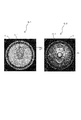
- FIG. 11 shows an image G of a tabbed can lid taken by the inspection camera 3.
- the image G is image-processed by the control unit 4, superimposed on appropriate dimensional coordinates, the tab t in the image G is extracted, and the coordinates of one end position t1 of the tab t are obtained. Further, the marking m in the image G is extracted, and the coordinates of the center position m1 of the marking m are obtained. Thereby, the distance S between the one end position t1 of the tab t and the center position m1 of the marking m in the tab t can be obtained. For this distance S, the set distance when the center position m1 is located at the position to be stamped is stored in advance, and the control unit 4 compares the set distance with the distance S obtained by image processing and makes a difference. Is recognized as the amount of deviation.
- the image G is acquired by the inspection camera 3 every time the can lid product W is sent out from the press machine 1, and the control unit 4 obtains the deviation amount as described above and makes the speed sensor 16 zero.
- the marking timing of the laser head 12 is controlled based on the output of. Further, the control unit 4 may control the feed mechanism 11 (feed roll 11A) so that the feed speed becomes the set speed based on the output of the speed sensor 16.
- FIG. 12 shows another specific example regarding the correction of the deviation of the marking position.
- the inspection camera 3 continuously acquires an image of the can lid to which the molded tabs are combined under an imaging condition in which the outline of the tab t can be extracted with high contrast and an imaging condition in which the marking can be extracted with high contrast.
- the image G1 and the image G2 of the two continuously acquired images are image-processed by the control unit 4 and superposed on one dimensional coordinate. Then, the tab t in the image G1 is extracted, the coordinates of one end position t1 of the tab t are obtained, the marking m in the image G2 is extracted, and the coordinates of the center position m1 of the marking m are obtained.
- the distance S between one end position t1 of the tab t and the center position m1 of the marking m in the tab t can be obtained as in the above-described example.
- Subsequent operations of the control unit 4 are the same as in the above-described example.
- the above-mentioned images G, G1 and G2 are photographed with the center position m1 of the engraved m aligned with the center of the captured image (center of the optical axis of the lens) of the inspection camera 3, thereby suppressing an error due to lens aberration and having high accuracy.
- the amount of deviation can be calculated with.
- the conversion press was used as the press machine 1, but in one press machine, only the tab is molded, the can lid is molded by another press machine, and this is combined with the tab after molding. You may do so.
- the coil material is sent to a press machine that forms tabs at a set speed, the coil material sent at the set speed is irradiated with laser light, and marking is performed for each tab.
- the tab after molding that comes out of the press machine is photographed with an inspection camera, the image acquired by the inspection camera is processed, the amount of deviation between the position to be engraved and the actual engraved position is obtained, and the amount of deviation is determined according to the amount of deviation. Controls the marking timing of the laser head. In that case, the marking position is detected before the molded tab is separated from the coil material, and the molded tab is supplied to another press machine in a state where it is not separated from the coil material. Will be done.
Landscapes
- Engineering & Computer Science (AREA)
- Mechanical Engineering (AREA)
- Physics & Mathematics (AREA)
- Optics & Photonics (AREA)
- Plasma & Fusion (AREA)
- Laser Beam Processing (AREA)
Abstract
缶の一部を成形するプレス機に供給されるコイル材に、成形対象毎のバリアブル刻印を行うに際して、高い生産性で刻印付きの成形対象を成形できるようにする。レーザー刻印装置は、缶の一部を成形するプレス機に供給されるコイル材に対してレーザー刻印を行う装置であって、コイル材を設定速度で送るフィード機構と、設定速度で送られるコイル材にレーザー光を照射して、成形対象毎に刻印を行うレーザーヘッドと、レーザーヘッドの刻印データを切り替えるデータ通信部とを備え、データ通信部は、複数の成形対象に刻印される複数個分の刻印データをまとめて切り替え、前記レーザーヘッドは、複数個分の刻印データを連続してコイル材の所定の位置に刻印する。
Description
本発明は、缶の一部を成形するプレス機に供給されるコイル材に対してレーザー刻印を行うレーザー刻印装置及びレーザー刻印方法、にレーザー刻印がなされたタブ付きの缶蓋を製造する製造装置及び製造方法に関するものである。
缶は、その一部に情報や絵柄などを付与することによって、加飾性を高めたり、製品個体の情報提供や製品個々の広告を行ったりすることがなされている。その中で、缶蓋の開口用タブは、缶を手にした人が、開口操作する際に特に注目する箇所であり、ステイオンタブ型の場合には、開口後も缶蓋本体から切り離されることがないので、その一部に情報や絵柄などを付与することによって、効果的に加飾性を高めたり、効果的に製品個体の情報提供を行ったりすることができる。
缶への情報や絵柄などの付与は、缶の表面に施されている塗膜に或いは缶の表面に直接レーザー光を照射して刻印を行う、レーザー刻印(レーザーマーキング)が採用されている。前述したタブへの刻印は、レーザー刻印を採用することで、比較的小さいスペースに高精細な刻印を行うことができる。缶の一部を成形するコイル材にレーザー刻印を行う装置(レーザー刻印装置)は、帯状の板材がロール状に巻かれているコイル材のロールと、ロールから引き出されたコイル材が供給されるプレス機との間にレーザーヘッドを配備しており、プレス機による成形を行う前に、プレス機に供給されるコイル材に対して、所定の位置にレーザー刻印を行っている(下記特許文献1参照)。
このようなレーザー刻印装置は、成形対象毎に異なる内容を刻印するバリアブル刻印が求められている。バリアブル刻印を行うためには、成形対象毎の刻印データを通信して、レーザーヘッドの動作プログラムを切り替えることが必要になる。この際、刻印データの切り替えに時間がかかることになり、実際にレーザーヘッドが一つの刻印データの内容を刻印する時間と成形対象毎の刻印データの切り替えに要する時間との合計時間によって、コイル材をプレス機に送るプレス1ストローク当たりの時間が制限されることになる。この制限が、刻印付きの成形対象を高い生産性で成形する上での障害になっていた。
また、このようなレーザー刻印装置は、コイル材をプレス機に送るフィード機構を備えており、このフィード機構の速度制御で、プレス機に送るコイル材の送り速度を調整している。これに対して、フィード機構の送り速度が変化すると、レーザーヘッドが配備されている箇所でコイル材に弛みが発生しやすくなり、弛みによってコイル材上の刻印位置に誤差が生じたり、刻印される文字などに歪みが生じたりする問題があった。
特に、コイル材の両面にレーザー刻印を行う場合には、コイル材の片面を台上に支持させることができないので、コイル材のレーザーヘッドに対面している部分は宙吊り状になっており、前述した弛みが生じ易くなっている。このため、コイル材の表裏両側にレーザーヘッドを配備して両面にレーザー刻印を行う場合には、前述した問題がより顕在化することになる。
また、タブなどの缶の一部へのレーザー刻印は、コイル材にレーザー刻印を行った後にプレス機によってタブなどの成形がなされることから、プレス機の成形型を変更した場合などで、タブなどの成形対象内の刻印されるべき位置と実際の刻印位置とにずれが生じる場合があり、このずれの修正に時間と労力を要することが問題になっていた。
また、従来技術においては、コイル材がプレス機に供給される前に、コイル材に付された位置合わせ用マークと刻印位置を検知して、レーザーヘッドの刻印タイミングを制御することがなされているが、これによると、プレス型の位置調整が必要な場合などでは、成形対象内の刻印されるべき位置と実際の刻印位置とのずれを正確に修正することができない問題が生じる。
更に、成形後の製品にキズや汚れがある場合には不良品になるので、前述した従来技術のように、コイル材がプレス機に供給される前に刻印位置の検知を行っていると、刻印位置の検知とは別に、製品のキズや汚れの検査を行うことになり、検査工程や検査のためのシステム構成が煩雑になる問題があった。
本発明は、このような問題に対処することを課題としている。すなわち、缶の一部を成形するプレス機に供給されるコイル材に、成形対象毎のバリアブル刻印を行うに際して、高い生産性で刻印付きの成形対象を成形できるようにすること、缶の一部を成形するプレス機に供給されるコイル材に、成形対象毎の刻印を行うに際して、コイル材の送り速度が変化した場合にも、コイル材の弛みを抑止して、精度の高い刻印を行うことができるようにすること、成形対象内の刻印されるべき位置と実際の刻印位置とのずれを正確且つ速やかに修正できるようにすること、刻印位置の検査と成形後の製品のキズや汚れの検査を含めた検査工程や検査システムを簡素化できるようにすること、などが本発明の課題である。
このような課題を解決するために、本発明は、以下の構成を具備するものである。
缶の一部を成形するプレス機に供給されるコイル材に対してレーザー刻印を行う装置であって、コイル材を設定速度で送るフィード機構と、設定速度で送られるコイル材にレーザー光を照射して、成形対象毎に刻印を行うレーザーヘッドと、前記レーザーヘッドの刻印データを切り替えるデータ通信部とを備え、前記データ通信部は、複数の成形対象に刻印される複数個分の刻印データをまとめて切り替え、前記レーザーヘッドは、複数個分の刻印データを連続してコイル材の所定の位置に刻印することを特徴とするレーザー刻印装置。
缶の一部を成形するプレス機に供給されるコイル材に対してレーザー刻印を行う装置であって、コイル材を設定速度で送るフィード機構と、設定速度で送られるコイル材にレーザー光を照射して、成形対象毎に刻印を行うレーザーヘッドと、前記レーザーヘッドの刻印データを切り替えるデータ通信部とを備え、前記データ通信部は、複数の成形対象に刻印される複数個分の刻印データをまとめて切り替え、前記レーザーヘッドは、複数個分の刻印データを連続してコイル材の所定の位置に刻印することを特徴とするレーザー刻印装置。
缶の一部を成形するプレス機に供給されるコイル材に対してレーザー刻印を行う刻印方法であって、レーザーヘッドが、プレス機に対して設定速度で送られるコイル材にレーザー光を照射して、成形対象毎に刻印を行うレーザー刻印工程と、前記レーザーヘッドの刻印データを切り替えるデータ通信工程とを有し、前記データ通信工程では、複数の成形対象に刻印される複数個の刻印データをまとめて切り替え、前記レーザー刻印工程では、複数個分の刻印データを連続して成形対象が成形される位置に刻印することを特徴とするレーザー刻印方法。
缶の一部を成形するプレス機に供給されるコイル材に対してレーザー刻印を行う刻印装置であって、コイル材を設定速度で送るフィード機構と、設定速度で送られるコイル材にレーザー光を照射して、成形対象毎に刻印を行うレーザーヘッドとを備え、前記フィード機構は、前記レーザーヘッドのコイル材送り方向下流側に設けられ、コイル材の送り速度を制御するフィードロールと、前記レーザーヘッドのコイル材送り方向上流側に設けられ、コイル材に張力を付与するテンションロールとを備え、前記テンションロールは、ロールに加わる負荷が一定になるように、ロールを駆動するモータのトルク制御を行うことを特徴とするレーザー刻印装置。
缶の一部を成形するプレス機に供給されるコイル材に対してレーザー刻印を行う刻印装置であって、コイル材を設定速度で前記プレス機に送るフィード機構と、設定速度で送られるコイル材にレーザー光を照射して、成形対象毎に刻印を行うレーザーヘッドと、前記プレス機から出てくる成形対象を撮影して、成形対象内の刻印位置を検査する画像を取得する検査カメラと、前記検査カメラが取得した画像を処理して、刻印すべき位置と実際の刻印位置とのずれ量を求め、該ずれ量に応じて前記レーザーヘッドの刻印タイミングを制御する制御部とを備えることを特徴とするレーザー刻印装置。
タブの成形を行うと共に缶蓋の成形を行い、成形されたタブと缶蓋の結合を行うプレス機と、コイル材を設定速度で前記プレス機に送るフィード機構と、設定速度で送られるコイル材にレーザー光を照射して、成形されるタブ毎に刻印を行うレーザーヘッドと、前記プレス機から出てくる成形後のタブ付き缶蓋を撮影して、成形されたタブ内の刻印位置を検査する画像を取得する検査カメラと、前記検査カメラが取得した画像を処理して、刻印すべき位置と実際の刻印位置とのずれ量を求め、該ずれ量に応じて前記レーザーヘッドの刻印タイミングを制御する制御部とを備えることを特徴とするタブ付き缶蓋の製造装置。
コイル材を設定速度でプレス機に送り、レーザーヘッドにより設定速度で送られるコイル材にレーザー光を照射して、成形されるタブ毎に刻印を行い、前記プレス機にて、タブの成形を行うと共に缶蓋の成形を行い、成形されたタブと缶蓋の結合を行い、前記プレス機から出てくる成形後のタブ付き缶蓋を撮影して、成形されたタブ内の刻印位置を検査する画像を取得し、取得した画像を処理して、刻印すべき位置と実際の刻印位置とのずれ量を求め、該ずれ量に応じて前記レーザーヘッドの刻印タイミングを制御することを特徴とするタブ付き缶蓋の製造方法。
このような特徴を有する本発明のレーザー刻印装置は、成形対象毎の刻印を複数個分まとめて切り替えることができるので、成形対象毎のバリアブル刻印を行う際にも、プレス1ストローク当たりの時間を短時間に設定して、刻印付きの成形対象を高い生産性で成形することができる。
缶の一部を成形するプレス機に供給されるコイル材に、成形対象毎の刻印を行うに際して、コイル材の送り速度が変化した場合にも、コイル材の弛みを抑止して、精度の高い刻印を行うことができる。
成形対象内の刻印されるべき位置と実際の刻印位置とのずれを正確且つ速やかに修正することができる。
また、タブ付き缶蓋の製品画像を検査カメラで取得するので、取得した画像で刻印位置の検査と成形後の製品のキズや汚れの検査を一元的に行うことができる。これによって検査工程や検査システムを簡素化することができる。
以下、図面を参照して本発明の実施形態を説明する。以下の説明で、異なる図における同一符号は同一機能の部位を示しており、各図における重複説明は適宜省略する。なお、以下の説明では、成形対象として、缶蓋のタブを例にして説明するが、本発明はこれに限定されるものではなく、コイル材から成形される缶蓋自体、缶胴、金属キャップなどの缶の一部を対象としている。
<第1実施形態>
先ず、図1において、タブ付きの缶蓋を成形するシステムの概略構成を説明する。この例では、タブの成形・蓋の加工・蓋とタブの結合を行うプレス機(コンバージョンプレス)1を用いている。タブが成形されるコイル材Tは、アルミニウム板の帯状板材であり、ロール状に巻かれたロールRから引き出されて、プレス機1に設定速度で供給される。プレス機1では、コイル材に対してのタブ成形がなされると共に、別ルートのコンベヤ2で供給される缶蓋パネルPの加工がなされ、成形されたタブが加工された缶蓋に結合された状態の缶蓋製品Wがプレス機1の出口から送り出される。
先ず、図1において、タブ付きの缶蓋を成形するシステムの概略構成を説明する。この例では、タブの成形・蓋の加工・蓋とタブの結合を行うプレス機(コンバージョンプレス)1を用いている。タブが成形されるコイル材Tは、アルミニウム板の帯状板材であり、ロール状に巻かれたロールRから引き出されて、プレス機1に設定速度で供給される。プレス機1では、コイル材に対してのタブ成形がなされると共に、別ルートのコンベヤ2で供給される缶蓋パネルPの加工がなされ、成形されたタブが加工された缶蓋に結合された状態の缶蓋製品Wがプレス機1の出口から送り出される。
なお、図示の例では、プレス機1としてコンバージョンプレスを行うものを例示しているが、これに限らず、プレス機1としては、タブのみを成形して、別のプレス機で缶蓋の成形とプレス機1で成形されたタブ(コイル材と分離されていないもの)とを結合するようにしてもよい。
タブに刻印を付与するレーザー刻印装置10は、ロールRから引き出されてプレス機1に供給されるコイル材Tに対して配備される。レーザー刻印装置10は、タブの成形が行われる前のコイル材Tに対して、プレス機1のストロークに対応する所定の位置にレーザー刻印を行うものである。
図2に示すように、レーザー刻印装置10は、コイル材Tを設定速度で矢印方向に送るフィード機構11(フィードロール11Aとテンションロール11B)と、設定速度で送られるコイル材Tにレーザー光を照射して、成形されるタブ毎に刻印を行うレーザーヘッド12(第1レーザーヘッドL1と第2レーザーヘッドL2と第3レーザーヘッドL3)と、レーザーヘッド12を制御する制御部13と、レーザーヘッド12に対しての刻印データを切り替えるデータ通信部14とを備えている。
図示の例では、レーザー刻印装置10は台部10Aを備えており、台部10A上に、フィード機構11或いはレーザーヘッド12が装備されるレーザー照射部15が配備されている。また、制御部13やデータ通信部14は、台部10A上に配備される図示省略した制御盤などに配備される。
レーザー刻印装置10は、コイル材Tの送り速度を計測する速度センサ16が装備されている。速度センサ16は、コイル材Tにレーザー光を照射して非接触でコイル材Tの送り速度を計測するレーザードップラー速度計を用いることができる。速度センサ16の出力は制御部13に送信され、計測された送り速度から送り量(距離)が算出される。制御部13は、速度センサ16の出力(コイル材Tの送り量)に応じてレーザーヘッド12の刻印タイミングを制御して、コイル材Tの所定の位置に刻印がなされるように制御している。
レーザーヘッド12は、データ通信部14で切り替えられる刻印データによって個々のタブ毎の刻印を行うものであり、図示の例では、レーザーヘッド12は、複数台(レーザーヘッドL1,L2,L3の3台)設けられており、データ通信部14は各々のレーザーヘッド12の刻印データを個別に切り替えている。
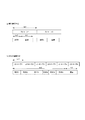
そして、レーザー刻印装置10のデータ通信部14は、図3の(a)に示すような、個別通信方式ではなく、図3の(b)に示すような、まとめ通信方式によってレーザーヘッド12の刻印データを切り替えている。図3の(a)に示す個別通信方式の場合には、次の刻印(例えば、「刻印2」)を行うために必要な刻印データ切り替えに要する通信時間tc1と実際に一つの刻印を行うのに必要な時間tw1を合わせた時間(tc1+tw1)より、プレス成形のストローク間の時間ts1を長く取る必要がある(すなわち、tc1+tw1<ts1)ので、ストローク間の時間ts1を短くするのに限界があり、高い生産性で刻印付きのタブを成形することができない。
これに対して、図3の(b)に示すまとめ通信方式を採用すると、1回の通信時間tc2で複数個分(図示の例では6個分)の刻印データが切り替えられるので、1回の通信時間tc2と複数の刻印(刻印1~刻印6)を連続して行う時間tw2とを合わせた時間(tc2+tw2)が、複数回のストロークに要する時間(ストローク1~ストローク6)内に収まれば良いことになり、ストローク間の時間(ts2)は短く設定することができる。これによって、高い生産性で刻印付きのタブを成形することができる。
まとめ通信方式で通信される複数の刻印データは、各タブに対応するように異なる刻印内容を含めることができる。この際、複数の刻印内容の中に比較的長い刻印時間を要する複雑な刻印が含まれる場合には、刻印時間が短い刻印内容との組み合わせを行うことで、ストローク時間を長くすること無く、複雑な刻印内容を含めることが可能になる。
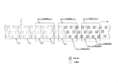
図4は、3台のレーザーヘッド12(L1,L2,L3)を用いて高い生産性で刻印付きのタブを成形する場合のレーザー刻印方法を示している。この例では、複数台のレーザーヘッド12(L1,L2,L3)は、各々のレーザーヘッドが分担する刻印位置(F1,F2,F3)がコイル材Tの送り方向に沿って順次区分されている。図示の例では、複数個分(6個分)の刻印が連続してなされる位置を一つの区分としており、レーザーヘッドL1が担当する区分(F1)とレーザーヘッドL2が担当する区分(F2)とレーザーヘッドL3が担当する区分(F3)が、順次コイル材Tの送り方向に沿って並んでいる。すなわち、コイル材Tの送り方向の逆側に向けて、F1の区分の隣にはF2の区分が設定され、F2の区分の隣にはF3の区分が設定されている。
このようなコイル材T上の刻印位置の設定に対して、複数台のレーザーヘッド12(L1,L2,L3)は、コイル材Tの長手方向に沿って配置されており、各レーザーヘッドL1,L2,L3の刻印エリアE1,E2,E3がコイル材Tの長手方向に沿って固定した状態で設定されている。ここで言う刻印エリアとは、一つのレーザーヘッドで刻印が可能な範囲を指している。
ここで、各レーザーヘッドL1,L2,L3は、それぞれ複数個分(6個分)の刻印データがまとめて切り替えられ、自身の刻印エリア(E1,E2,E3)の所定の位置に自身の担当する刻印位置の区分(F1,F2,F3)が来たときに、その区分内の所定位置に複数(6個)の刻印を連続して行う。
レーザーヘッドL1の動作を個別に説明すると、コイル材Tが図示の矢印方向に送られ、刻印エリアE1に区分F1が入り、レーザーヘッドL1によって複数の刻印が連続して行われた直後は、刻印エリアE1には、レーザーヘッドL2が担当する区分F2とレーザーヘッドL3が担当する区分F3が順次入ることになる(その前段で区分F2,F3には既に刻印が行われている)。レーザーヘッドL2,L3の動作も同様である。
図5は、図4に示した例の刻印位置の移動を示している。コイル材Tの移動距離は、プレスのストロークに依存しており、1ストロークでのコイル材Tの移動距離は図示の例ではS1に設定されている。図示のように、一つの刻印位置の区分(F1)が一つの刻印エリア(E1)に入って全て出るまでのストローク数は6ストロークになり、このストローク数と一つの刻印位置の区分(F1)内の刻印データの数は、同一となる様に設定されている。
そして、一つのレーザーヘッド12に対しては、自身が担当する刻印位置の区分F1が自身のレーザーヘッドの刻印エリアE1を通過する間に、各区分で刻印する複数個分(6個分)の刻印データを刻印し、自身が担当する次の刻印位置の区分が自身のレーザーヘッドの刻印エリアに入るまでに、刻印データの切り替えを行う。
このような刻印方法によると、複数台のレーザーヘッドをコイル材の送り方向に沿って配備し、コイル材Tの上に各レーザーヘッドが分担する刻印位置の区分をコイル材Tの送り方向に沿って順次区分けすることで、プレスのストローク時間を短く設定しても、タブ毎のバリアブル刻印を円滑に行うことができる。
図6は、3台のレーザーヘッド12(L1,L2,L3)を用いて高い生産性で刻印付きのタブを成形する場合の他の刻印方法を示している。この例では、複数台のレーザーヘッド12(L1,L2,L3)は、コイル材Tに成形されるタブの列毎に配置されており、成形されるタブの列毎に各々のレーザーヘッドが分担する刻印位置が区分されている。具体的には、レーザーヘッドL1の刻印エリアE1とレーザーヘッドL2の刻印エリアE2とレーザーヘッドL3の刻印エリアE3が、成形されるタブの3列にそれぞれ並列されている。
これによると、各レーザーヘッド(L1,L2,L3)が複数個分(例えば6個分)の刻印データを連続して所定位置に刻印するには、図6に示す動作チャートのように、複数のストローク(6ストローク)の時間内に、複数の刻印(刻印1~刻印6)時間twと次の刻印を行うための刻印データを複数個分まとめて切り替える通信時間tcを収めることが必要になる。
これによると、成形されるタブの列毎に1台のレーザーヘッドを対応させているので、各列の刻印位置の補正をレーザーヘッド毎に行うことができ、また、刻印エラーが発生した場合に修正すべきレーザーヘッドを特定しやすくなるなど、制御や管理の上での利点が得やすくなる。
以上説明したように、本発明の第1実施形態に係るタブの刻印装置及び刻印方法によると、タブ成形のプレス機のストローク間の時間を短くして生産性を高めた場合であっても、コイル材へのバリアブル刻印を円滑に行うことができる。よって、生産性を低下させること無く、様々な絵柄や情報を随時変更しながら、コイル材に刻印することが可能になる。
<第2実施形態>
第2実施形態においても、図1とその説明は共通する。
第2実施形態においても、図1とその説明は共通する。
第2実施形態においては、図7に示すように、レーザー刻印装置10は、コイル材Tを設定速度で矢印方向に送るフィード機構11(フィードロール11Aとテンションロール11B)と、設定速度で送られるコイル材Tにレーザー光を照射して、成形されるタブ毎に刻印を行うレーザーヘッド12(第1レーザーヘッドL1、第2レーザーヘッドL2、第3レーザーヘッドL3、第4レーザーヘッドL4、第5レーザーヘッドL5、第6レーザーヘッドL6)と、レーザーヘッド12を制御する制御部13と、レーザーヘッド12に対しての刻印データを切り替えるデータ通信部14とを備えている。
図示の例では、レーザー刻印装置10は台部10Aを備えており、台部10A上に、フィード機構11或いはレーザーヘッド12が装備されるレーザー照射部15が配備されている。また、制御部13やデータ通信部14は、台部10A上に配備される図示省略した制御盤などに配備される。
レーザー刻印装置10は、コイル材Tの送り速度を非接触で計測する速度センサ16が装備されている。速度センサ16は、フィードロールの近傍(好ましくはフィードロール11Aと11B間)に設けられており、コイル材Tにレーザー光を照射して非接触でコイル材Tの送り速度を計測するレーザードップラー速度計を用いることができる。速度センサ16の出力は、制御部13に送信され、計測された送り速度から送り量(距離)が算出されている。制御部13は、速度センサ16の出力(コイル材Tの送り量(距離))に応じてレーザーヘッド12の刻印タイミングを制御している。また、制御部13が、速度センサ16の出力に応じてフィードロールの回転制御を行うようにしてもよい。
図8にて、フィード機構11におけるコイル材Tのテンション制御を説明する。フィードロール11Aは、モータ(サーボモータ)20の出力軸20Aにて回転駆動されている。速度制御部13Aは、プレス機1における生産状況等を考慮して、設定速度でモータ20を回転させて、コイル材Tを設定した送り速度でプレス機1に送っている。
テンションロール11Bは、モータ(サーボモータ)21の出力軸21Aにて回転駆動され、モータ21は、出力軸21Aに設けられるトルクセンサ23によって検知される負荷トルクに応じて、トルク制御部22から出力される制御信号によってトルク制御されている。トルク制御部22は、フィードロール11Aを回転駆動するモータ20の回転速度よりも遅い速度を初期値として設定して、トルクセンサ23が検出する負荷トルクが一定になるように、モータ21の回転を制御している。
これによると、速度制御部13Aによって設定されるコイル材Tの送り速度が適宜変更された場合であっても、テンションロール11Bは、一定の負荷状態で回転駆動されることになる。テンションロール11Bに加わる負荷は、コイル材Tのテンション(張力)と同等になるから、テンションロール11Bを回転駆動するモータ22をトルク制御することで、フィードロール11Aとテンションロール11Bとの間のコイル材のテンションが常時一定に制御されることになる。
このような制御を行うことで、コイル材の速度変化に対して、フィードロール11Aとテンションロール11Bとの間のコイル材のテンションを高い応答性で一定に維持することができ、ロール間のコイル材Tの弛みを抑止することができる。これによって、フィードロール11Aとテンションロール11Bとの間に配備されるレーザーヘッド12によるコイル材への刻印を高い精度で行うことが可能になる。
ロール巻きのフィルム材などで一般に行われているテンション制御は、ロール間のフィルムのテンションを検出することで、前段と後段のロールの回転速度差を制御しているが、これによると、テンションの変動に対して速度応答性が低くなり、高い応答性でテンションを一定に維持することができない。
図8に示すように、テンションロール11Bをトルク制御することで、コイル材Tのテンション制御を行うと、フィードロール11Aとテンションロール11Bとの間にテンション検出器を置く必要が無いので、フィードロール11Aとテンションロール11Bの間に複数のレーザーヘッド12を並べて配置するためのスペースを十分に確保することが可能になる。
また、図7に示すように、レーザーヘッド12を、フィードロール11Aとテンションロール11Bとの間でコイル材Tに対して表裏両面側にそれぞれ配置した場合にも、弛みが抑えられたコイル材Tの表裏両面に精度の高いレーザー刻印を行うことができる。コイル材Tの表裏両面に同時にレーザー刻印を行おうとすると、コイル材はロール間で宙吊り状にならざるを得ないが、ロール間のコイル材Tの弛みが抑えられていることで、表裏のレーザー刻印を同等の精度で行うことができる。
前述したように、コイル材Tの表裏両面側にそれぞれレーザーヘッド12を配備する際に、レーザーヘッド12に対面するコイル材Tの送り姿勢は、水平であっても垂直であっても良く、また、斜めに傾斜した状態であっても良い。
タブTの送り姿勢を水平にした場合には、レーザーヘッド12はコイル材Tの上下に配置されることになる。この場合は、コイル材Tの左右のスペースを省スペース化することができる。コイル材Tの送り姿勢を垂直にした場合には、レーザーヘッド12はコイル材Tの左右に配置されることになる。この場合には、コイル材Tにレーザー光を照射することで発生する塵(アルミ粉やヒュームなど)がコイル材T上やレーザーヘッドのレンズ上に落ちるリスクが少なくなる。
レーザーヘッド12のレーザー光源は、ファイバーレーザー、UVレーザー、CO2レーザーなど、用途に応じて様々なものを用いることができる。ファイバーレーザーは、ファイバーをレーザー媒質として利用する形式のレーザーであり、低コストでスペース効率が高く、レーザー光を光ファイバーに直接導入して目的位置まで伝送し易い。このため、レーザーマーカーに一般に用いられている。
UVレーザーは、短波長域のレーザー光を照射することができるレーザーであり、コイル材Tの表面塗料の有機物に短波長のレーザー光を照射することで、表面塗料の分子構造を破壊することによる刻印が可能になる。これによると、残渣の少ない刻印を行うことできる。CO2レーザーは、長波長のレーザー光を照射することができるレーザーであり、コイル材Tの基材であるアルミニウムへの吸収率が低いため、基材の変質を抑えて表面塗料のみを選択的に加熱する刻印が可能になる。
以上説明したように、本発明の第2実施形態に係るレーザー刻印装置10は、コイル材Tのテンション変動に対しての速度応答性が優れており、フィードロール11Aとテンションロール11Bとの間でコイル材Tの弛みが発生し難いので、レーザー刻印する際のコイル材Tのフラット面を確保することができ、精度の高い刻印が可能になる。
また、フィードロール11Aとテンションロール11Bとの間でコイル材Tを支持する必要が無いので、レーザーヘッド12を複数並べて配置するスペースを十分に確保することができると共に、コイル材Tの表裏両面側にレーザーヘッド12を配置して表裏への同時刻印を高い精度で行うことができる
<第3実施形態>
図9において、図1との共通部位は説明を省略する。
図9において、図1との共通部位は説明を省略する。
第3実施形態においては、図9に示すように、プレス機1から出てくる成形後のタブは、タブ付きの缶蓋製品Wとして、検査カメラ3にて撮影される。検査カメラ3が取得する缶蓋製品Wの画像は、成形されたタブ内の刻印位置を検査するための画像であり、取得した画像は、制御部4に送信される。制御部4は、検査カメラ3が取得した画像を処理して、成形されたタブ内において、刻印すべき位置と実際の刻印位置とのずれ量を求め、このずれ量に応じてレーザー刻印装置10におけるレーザーヘッドの刻印タイミングを制御する。
第3実施形態におけるレーザー刻印装置10は、図10に示すように、コイル材Tを設定速度で矢印方向に送るフィード機構11(フィードロール11Aとテンションロール11B)と、設定速度で送られるコイル材Tにレーザー光を照射して、成形されるタブ毎に刻印を行うレーザーヘッド12(第1レーザーヘッドL1、第2レーザーヘッドL2、第3レーザーヘッドL3)と、レーザーヘッド12を制御する前述した制御部4とを備えている。
図示の例では、レーザー刻印装置10は台部10Aを備えており、台部10A上に、フィード機構11或いはレーザーヘッド12が装備されるレーザー照射部15が配備されている。また、制御部4は、台部10A上に配備される図示省略した制御盤などに配備される。
レーザー刻印装置10は、コイル材Tの送り速度を非接触で計測する速度センサ16が装備されている。速度センサ16は、コイル材Tにレーザー光を照射して非接触でコイル材Tの送り速度を計測するレーザードップラー速度計を用いることができる。この速度センサ16は、フィードロール11Aの近傍に設けることが好ましい。速度センサ16をフィードロール11Aの近くに配置すると、フィードロール11Aの近くで振動の少ないコイル材Tに対して非接触で送り速度を計測するので、高い精度での計測が可能になる。速度センサ16の出力は制御部4に送信される。制御部4は、速度センサ16の出力と前述したずれ量に応じてレーザーヘッド12の刻印タイミングを制御する。
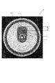
制御部4による刻印位置のずれ補正について、具体例を説明する。図11は、検査カメラ3で撮影されるタブ付き缶蓋の画像Gを示している。画像Gは、制御部4にて画像処理され、適当な寸法座標上に重ねられ、画像Gの中のタブtが抽出され、タブtの一端位置t1の座標が求められる。また、画像Gの中の刻印mが抽出され、刻印mの中心位置m1の座標が求められる。これによって、前述したタブtの一端位置t1とタブt内の刻印mの中心位置m1との距離Sを求めることができる。この距離Sは、刻印すべき位置に中心位置m1がある場合の設定距離が予め記憶されており、制御部4は、その設定距離と画像処理で求めた距離Sとを比較して、その差をずれ量として認識する。
画像Gは、缶蓋製品Wがプレス機1から送り出される度に検査カメラ3によって取得され、制御部4は、前述したようにずれ量を求めると、これをゼロにするように、速度センサ16の出力に基づいてレーザーヘッド12の刻印タイミングを制御している。また、制御部4は、速度センサ16の出力に基づいて、送り速度が設定速度になるように、フィード機構11(フィードロール11A)を制御するようにしてもよい。
図12は、刻印位置のずれ補正に関する他の具体例を示している。この例では、検査カメラ3が、成形されたタブが結合された缶蓋の画像をタブtの輪郭が高いコントラストで抽出できる撮像条件と、刻印が高いコントラストで抽出できる撮像条件で連続取得する。連続取得された2つの画像のうちの画像G1と画像G2が、制御部4にて画像処理され、一つの寸法座標上に重ねられる。そして、画像G1の中のタブtが抽出され、タブtの一端位置t1の座標が求められ、画像G2の中の刻印mが抽出され、刻印mの中心位置m1の座標が求められる。これによって、前述した例と同様に、タブtの一端位置t1とタブt内の刻印mの中心位置m1との距離Sを求めることができる。その後の制御部4の動作は前述した例と同様である。
また、前述した画像G,G1,G2は、刻印mの中心位置m1を検査カメラ3の撮影画像中心(レンズの光軸中心)に合わせて撮影することで、レンズ収差による誤差を抑えて高い精度でずれ量を求めることができる。
更に、前述したように2つの画像G1,G2を連続撮影する場合には、一方の画像G1で缶蓋のキズや汚れの検査を行うようにすることで、別の検査工程を追加すること無く、刻印位置の検査と成形後の製品のキズや汚れの検査を一元的に行うことができる。これによって検査工程や検査システムを簡素化することができる。2つの画像G1,G2の一方でキズや汚れの検査を行う例を説明したが、図11に示すように、一つの画像Gでずれ量を求める場合にも、撮影条件を適宜調整することで、一つの画像Gで成形後の製品のキズや汚れの検査を行うことができる。
前述した説明では、プレス機1としてコンバージョンプレスを用いたが、一つのプレス機では、タブのみの成形を行い、別のプレス機で缶蓋を成形して、これを成形後のタブと結合するようにしてもよい。この場合、コイル材を設定速度でタブを成形するプレス機に送り、設定速度で送られるコイル材にレーザー光を照射して、タブ毎に刻印を行う。そして、プレス機から出てくる成形後のタブを検査カメラで撮影し、検査カメラが取得した画像を処理して、刻印すべき位置と実際の刻印位置とのずれ量を求め、ずれ量に応じてレーザーヘッドの刻印タイミングを制御する。その際には、成形されたタブがコイル材から切り離される前の状態で刻印位置が検出されることになり、成形されたタブがコイル材から分離されていない状態で、別のプレス機に供給される。
以上、本発明の実施の形態について図面を参照して詳述してきたが、具体的な構成はこれらの実施の形態に限られるものではなく、本発明の要旨を逸脱しない範囲の設計の変更等があっても本発明に含まれる。また、上述の各実施の形態は、その目的及び構成等に特に矛盾や問題がない限り、互いの技術を流用して組み合わせることが可能である。
Claims (25)
- 缶の一部を成形するプレス機に供給されるコイル材に対してレーザー刻印を行う装置であって、
コイル材を設定速度で送るフィード機構と、
設定速度で送られるコイル材にレーザー光を照射して、成形対象毎に刻印を行うレーザーヘッドと、
前記レーザーヘッドの刻印データを切り替えるデータ通信部とを備え、
前記データ通信部は、複数の成形対象に刻印される複数個分の刻印データをまとめて切り替え、前記レーザーヘッドは、複数個分の刻印データを連続してコイル材の所定の位置に刻印することを特徴とするレーザー刻印装置。 - 前記複数個分の刻印データが、異なる刻印内容を含むことを特徴とする請求項1に記載されたレーザー刻印装置。
- 前記レーザーヘッドを複数台備え、
前記データ通信部が、複数台の前記レーザーヘッドのそれぞれに対して複数個分の刻印データを切り替えることを特徴とする請求項1又は2に記載されたレーザー刻印装置。 - 複数台の前記レーザーヘッドは、各々のレーザーヘッドが分担する刻印位置がコイル材の送り方向に沿って順次区分されており、
一つの前記レーザーヘッドに対しては、自身が担当する刻印位置の区分が自身のレーザーヘッドの刻印エリアを通過する間に、各区分で刻印する複数個分の刻印データを刻印し、自身が担当する次の刻印位置の区分が自身のレーザーヘッドの刻印エリアに入るまでに、刻印データの切り替えを行うことを特徴とする請求項3に記載されたレーザー刻印装置。 - 複数台の前記レーザーヘッドが、前記コイル材の長手方向に沿って配置されることを特徴とする請求項4に記載されたレーザー刻印装置。
- 複数台の前記レーザーヘッドが、前記コイル材に成形される成形対象の列毎に各々のレーザーヘッドが分担する刻印位置が区分されていることを特徴とする請求項3に記載されたレーザー刻印装置。
- 前記成形対象が、缶蓋のタブである請求項1~6のいずれか1項記載のレーザー刻印装置。
- 缶の一部を成形するプレス機に供給されるコイル材に対してレーザー刻印を行う刻印方法であって、
レーザーヘッドが、プレス機に対して設定速度で送られるコイル材にレーザー光を照射して、成形対象毎に刻印を行うレーザー刻印工程と、
前記レーザーヘッドの刻印データを切り替えるデータ通信工程とを有し、
前記データ通信工程では、複数の成形対象に刻印される複数個の刻印データをまとめて切り替え、前記レーザー刻印工程では、複数個分の刻印データを連続して成形対象が成形される位置に刻印することを特徴とするレーザー刻印方法。 - 缶の一部を成形するプレス機に供給されるコイル材に対してレーザー刻印を行う刻印装置であって、
コイル材を設定速度で送るフィード機構と、
設定速度で送られるコイル材にレーザー光を照射して、成形対象毎に刻印を行うレーザーヘッドとを備え、
前記フィード機構は、
前記レーザーヘッドのコイル材送り方向下流側に設けられ、コイル材の送り速度を制御するフィードロールと、
前記レーザーヘッドのコイル材送り方向上流側に設けられ、コイル材に張力を付与するテンションロールとを備え、
前記テンションロールは、ロールに加わる負荷が一定になるように、ロールを駆動するモータのトルク制御を行うことを特徴とするレーザー刻印装置。 - 前記レーザーヘッドが、前記フィードロールと前記テンションロールとの間のコイル材に対して、表裏両面側にそれぞれ配置されていることを特徴とする請求項9記載のレーザー刻印装置。
- 前記フィードロールの近傍には、コイル材の送り速度を非接触で測定する速度センサが設けられ、前記速度センサの出力に応じて前記レーザーヘッドの刻印タイミングが制御されることを特徴とする請求項9又は10に記載のレーザー刻印装置。
- 前記レーザーヘッドに対面するコイル材の送り姿勢が水平になっていることを特徴とする請求項9~11のいずれか1項に記載のレーザー刻印装置。
- 前記レーザーヘッドに対面するコイル材の送り姿勢が垂直になっていることを特徴とする請求項9~11のいずれか1項に記載のレーザー刻印装置。
- 前記成形対象が、缶蓋のタブである請求項9~13のいずれか1項記載のレーザー刻印装置。
- 缶の一部を成形するプレス機に供給されるコイル材に対してレーザー刻印を行う刻印装置であって、
コイル材を設定速度で前記プレス機に送るフィード機構と、
設定速度で送られるコイル材にレーザー光を照射して、成形対象毎に刻印を行うレーザーヘッドと、
前記プレス機から出てくる成形対象を撮影して、成形対象内の刻印位置を検査する画像を取得する検査カメラと、
前記検査カメラが取得した画像を処理して、刻印すべき位置と実際の刻印位置とのずれ量を求め、該ずれ量に応じて前記レーザーヘッドの刻印タイミングを制御する制御部とを備えることを特徴とするレーザー刻印装置。 - 前記制御部は、成形対象の一端から刻印の中心位置までの距離を求め、該距離を設定距離と比較して前記ずれ量を求めることを特徴とする請求項15に記載されたレーザー刻印装置。
- 前記検査カメラは、撮影画像中心を前記刻印の中心位置に合わせていることを特徴とする請求項16記載のレーザー刻印装置。
- 前記制御部は、前記検査カメラが取得した一つの画像を処理して、前記ずれ量を求めることを特徴とする請求項15~17のいずれか1項記載のレーザー刻印装置。
- 前記検査カメラは少なくとも二つの画像を取得するものであり、前記制御部は、前記検査カメラが取得した一つの画像で前記成形対象の一端位置を求め、他の画像で前記刻印の中心位置を求めることを特徴とする請求項15~17のいずれか1項に記載されたレーザー刻印装置。
- 前記プレス機は、複数の成形対象の成形と結合を行うコンバージョンプレスであり、
前記検査カメラは、結合された製品における前記画像を取得することを特徴とする請求項15~19のいずれか1項に記載されたレーザー刻印装置。 - 前記制御部は、前記画像で、製品のキズや汚れ検査を行うことを特徴とする請求項15~20のいずれか1項に記載されたレーザー刻印装置。
- コイル材の送り速度を非接触で計測する速度センサが設けられ、前記速度センサの出力に基づいて、前記レーザーヘッドの刻印タイミングが制御されることを特徴とする請求項15~21のいずれか1項に記載のレーザー刻印装置。
- 前記成形対象が、缶蓋のタブである請求項15~22のいずれか1項記載のレーザー刻印装置。
- タブの成形を行うと共に缶蓋の成形を行い、成形されたタブと缶蓋の結合を行うプレス機と、
コイル材を設定速度で前記プレス機に送るフィード機構と、
設定速度で送られるコイル材にレーザー光を照射して、成形されるタブ毎に刻印を行うレーザーヘッドと、
前記プレス機から出てくる成形後のタブ付き缶蓋を撮影して、成形されたタブ内の刻印位置を検査する画像を取得する検査カメラと、
前記検査カメラが取得した画像を処理して、刻印すべき位置と実際の刻印位置とのずれ量を求め、該ずれ量に応じて前記レーザーヘッドの刻印タイミングを制御する制御部とを備えることを特徴とするタブ付き缶蓋の製造装置。 - コイル材を設定速度でプレス機に送り、
レーザーヘッドにより設定速度で送られるコイル材にレーザー光を照射して、成形されるタブ毎に刻印を行い、
前記プレス機にて、タブの成形を行うと共に缶蓋の成形を行い、成形されたタブと缶蓋の結合を行い、
前記プレス機から出てくる成形後のタブ付き缶蓋を撮影して、成形されたタブ内の刻印位置を検査する画像を取得し、
取得した画像を処理して、刻印すべき位置と実際の刻印位置とのずれ量を求め、該ずれ量に応じて前記レーザーヘッドの刻印タイミングを制御することを特徴とするタブ付き缶蓋の製造方法。
Priority Applications (2)
| Application Number | Priority Date | Filing Date | Title |
|---|---|---|---|
| CN202080022042.9A CN113613824A (zh) | 2019-03-19 | 2020-03-04 | 激光刻印装置及激光刻印方法、带拉环的罐盖的制造装置及制造方法 |
| US17/439,099 US20220143754A1 (en) | 2019-03-19 | 2020-03-04 | Laser engraving device, laser engraving method, and device and method for manufacturing can lid having tab |
Applications Claiming Priority (6)
| Application Number | Priority Date | Filing Date | Title |
|---|---|---|---|
| JP2019-051707 | 2019-03-19 | ||
| JP2019-051713 | 2019-03-19 | ||
| JP2019051713A JP7351090B2 (ja) | 2019-03-19 | 2019-03-19 | レーザー刻印装置 |
| JP2019051707A JP7640221B2 (ja) | 2019-03-19 | 2019-03-19 | レーザー刻印装置及びレーザー刻印方法 |
| JP2019051717A JP7549953B2 (ja) | 2019-03-19 | 2019-03-19 | レーザー刻印装置、タブ付き缶蓋の製造装置及び製造方法 |
| JP2019-051717 | 2019-03-19 |
Publications (1)
| Publication Number | Publication Date |
|---|---|
| WO2020189276A1 true WO2020189276A1 (ja) | 2020-09-24 |
Family
ID=72519848
Family Applications (1)
| Application Number | Title | Priority Date | Filing Date |
|---|---|---|---|
| PCT/JP2020/009116 Ceased WO2020189276A1 (ja) | 2019-03-19 | 2020-03-04 | レーザー刻印装置及びレーザー刻印方法、タブ付き缶蓋の製造装置及び製造方法 |
Country Status (3)
| Country | Link |
|---|---|
| US (1) | US20220143754A1 (ja) |
| CN (1) | CN113613824A (ja) |
| WO (1) | WO2020189276A1 (ja) |
Cited By (2)
| Publication number | Priority date | Publication date | Assignee | Title |
|---|---|---|---|---|
| JP2022130978A (ja) * | 2021-02-26 | 2022-09-07 | 株式会社リコー | レーザ照射装置、レーザ照射方法、収容器および収容体 |
| JP2023084716A (ja) * | 2021-12-08 | 2023-06-20 | 株式会社リコー | レーザ照射装置及びレーザ照射方法 |
Families Citing this family (2)
| Publication number | Priority date | Publication date | Assignee | Title |
|---|---|---|---|---|
| CN116078946A (zh) * | 2022-12-29 | 2023-05-09 | 无锡华鹏瓶盖有限公司 | 带码瓶盖生产方法及生产系统 |
| CN116174915B (zh) * | 2022-12-30 | 2025-07-29 | 南昌华勤电子科技有限公司 | 多任务量工件的批量化镭雕方法及系统 |
Citations (8)
| Publication number | Priority date | Publication date | Assignee | Title |
|---|---|---|---|---|
| JPH10329087A (ja) * | 1997-05-30 | 1998-12-15 | Lintec Corp | 半導体ウェハ保護フィルムの切断方法および装置 |
| JP2000015463A (ja) * | 1998-07-02 | 2000-01-18 | Keyence Corp | レーザマーキング装置 |
| JP2002520164A (ja) * | 1998-07-16 | 2002-07-09 | ボール コーポレイション | レーザー光を用いて容器にマーキングを施す方法及び装置 |
| JP2003112736A (ja) * | 2001-10-09 | 2003-04-18 | Toyo Seikan Kaisha Ltd | レーザーマーク付き缶蓋 |
| JP2003136260A (ja) * | 2001-10-31 | 2003-05-14 | Sunx Ltd | レーザマーキング装置 |
| JP2009039753A (ja) * | 2007-08-09 | 2009-02-26 | Canon Machinery Inc | レーザ捺印装置およびレーザ捺印方法 |
| WO2011010623A1 (ja) * | 2009-07-24 | 2011-01-27 | 旭硝子株式会社 | ガラス部材の品質管理方法及び品質管理装置、並びにマーク付きガラス部材 |
| JP2015531684A (ja) * | 2012-08-13 | 2015-11-05 | クラウン・パッケージング・テクノロジー・インク | レーザマーキングシステムおよび方法 |
Family Cites Families (8)
| Publication number | Priority date | Publication date | Assignee | Title |
|---|---|---|---|---|
| US4635545A (en) * | 1984-12-24 | 1987-01-13 | American Can Company | Apparatus for marking moving articles |
| US6105806A (en) * | 1997-08-26 | 2000-08-22 | Stasiuk; Joseph W. | Laser etched pull tab container opening devices and methods of making the same |
| PL2093041T3 (pl) * | 2006-10-17 | 2013-08-30 | Nitto Denko Corp | Sposób przyklejania elementu optycznego i urządzenie wykorzystujące ten sposób |
| JP5224343B2 (ja) * | 2008-06-13 | 2013-07-03 | 株式会社ブイ・テクノロジー | レーザ加工装置 |
| FR2961118B1 (fr) * | 2010-06-11 | 2013-03-01 | Michelin Soc Tech | Dispositif et procede de nettoyage d'un fil |
| JP5740921B2 (ja) * | 2010-11-05 | 2015-07-01 | 大日本印刷株式会社 | レーザ加工装置、レーザ加工システム |
| US10421111B2 (en) * | 2015-04-17 | 2019-09-24 | Ball Corporation | Method and apparatus for controlling an operation performed on a continuous sheet of material |
| JP5884932B1 (ja) * | 2015-05-27 | 2016-03-15 | 千住金属工業株式会社 | 液体塗布装置 |
-
2020
- 2020-03-04 US US17/439,099 patent/US20220143754A1/en not_active Abandoned
- 2020-03-04 WO PCT/JP2020/009116 patent/WO2020189276A1/ja not_active Ceased
- 2020-03-04 CN CN202080022042.9A patent/CN113613824A/zh active Pending
Patent Citations (8)
| Publication number | Priority date | Publication date | Assignee | Title |
|---|---|---|---|---|
| JPH10329087A (ja) * | 1997-05-30 | 1998-12-15 | Lintec Corp | 半導体ウェハ保護フィルムの切断方法および装置 |
| JP2000015463A (ja) * | 1998-07-02 | 2000-01-18 | Keyence Corp | レーザマーキング装置 |
| JP2002520164A (ja) * | 1998-07-16 | 2002-07-09 | ボール コーポレイション | レーザー光を用いて容器にマーキングを施す方法及び装置 |
| JP2003112736A (ja) * | 2001-10-09 | 2003-04-18 | Toyo Seikan Kaisha Ltd | レーザーマーク付き缶蓋 |
| JP2003136260A (ja) * | 2001-10-31 | 2003-05-14 | Sunx Ltd | レーザマーキング装置 |
| JP2009039753A (ja) * | 2007-08-09 | 2009-02-26 | Canon Machinery Inc | レーザ捺印装置およびレーザ捺印方法 |
| WO2011010623A1 (ja) * | 2009-07-24 | 2011-01-27 | 旭硝子株式会社 | ガラス部材の品質管理方法及び品質管理装置、並びにマーク付きガラス部材 |
| JP2015531684A (ja) * | 2012-08-13 | 2015-11-05 | クラウン・パッケージング・テクノロジー・インク | レーザマーキングシステムおよび方法 |
Cited By (5)
| Publication number | Priority date | Publication date | Assignee | Title |
|---|---|---|---|---|
| JP2022130978A (ja) * | 2021-02-26 | 2022-09-07 | 株式会社リコー | レーザ照射装置、レーザ照射方法、収容器および収容体 |
| US12152873B2 (en) | 2021-02-26 | 2024-11-26 | Ricoh Company, Ltd. | Laser irradiation apparatus, laser irradiation method, container, and containment body |
| JP7600754B2 (ja) | 2021-02-26 | 2024-12-17 | 株式会社リコー | レーザ照射装置、レーザ照射方法 |
| JP2023084716A (ja) * | 2021-12-08 | 2023-06-20 | 株式会社リコー | レーザ照射装置及びレーザ照射方法 |
| JP7790117B2 (ja) | 2021-12-08 | 2025-12-23 | 株式会社リコー | レーザ照射装置及びレーザ照射方法 |
Also Published As
| Publication number | Publication date |
|---|---|
| CN113613824A (zh) | 2021-11-05 |
| US20220143754A1 (en) | 2022-05-12 |
Similar Documents
| Publication | Publication Date | Title |
|---|---|---|
| ES2386548T3 (es) | Dispositivo y procedimiento para el ajuste de la imagen de impresión en una máquina de impresión flexográfica | |
| JP6181556B2 (ja) | デコレータ構成部品の識別及びその選択調整のための方法及びシステム | |
| TWI748696B (zh) | 用於決定印刷機之印刷參數的方法及測試平台 | |
| CN113613824A (zh) | 激光刻印装置及激光刻印方法、带拉环的罐盖的制造装置及制造方法 | |
| CN110785248B (zh) | 增材制造装置的功率辐射源的头部系统校准 | |
| JPH02501373A (ja) | 多色‐輪転印刷機における版胴を互いに位置決めするための方法 | |
| KR20200020802A (ko) | 적층 제조 디바이스의 출력 복사선 소스의 초점 교정 | |
| EP3941676B1 (en) | Characterization method and system for a laser processing machine with a moving sheet or web | |
| CN115041705A (zh) | 多激光三轴振镜校准方法、系统、设备及可读存储介质 | |
| JP2011251533A (ja) | 印刷機を見当制御するための方法及び装置 | |
| WO2017194968A1 (en) | System and method for cutting, kiss-cutting, scoring or perforating material | |
| US20090283002A1 (en) | Method for printing correction | |
| EP2749417A1 (en) | Quality control, method and device in production lines of solid and corrugated carton boxes, and advertising displays made of paper | |
| CN114379223A (zh) | 用于运行柔版印刷机的方法、柔版印刷机、系统和套筒 | |
| US10525697B2 (en) | Inspection system having a plurality of detection zones | |
| US7966935B2 (en) | Registering method | |
| JP7549953B2 (ja) | レーザー刻印装置、タブ付き缶蓋の製造装置及び製造方法 | |
| JP7640221B2 (ja) | レーザー刻印装置及びレーザー刻印方法 | |
| JP7153297B2 (ja) | 印刷版の校正装置、校正方法、および、印刷版の納入方法 | |
| JP2006224673A (ja) | 印刷修正を実施する方法および印刷修正を実施する装置 | |
| CN102177028B (zh) | 编号机的承载盘和编号单元的设置和调试 | |
| CN204347331U (zh) | 一种闭环控制焦距调节装置 | |
| JP2020151743A (ja) | レーザー刻印装置 | |
| EP4385743A1 (en) | Method and device for synchronising a process for printing on cardboard | |
| CA2505170A1 (en) | Method for calibrating a write head for producing a printing plate |
Legal Events
| Date | Code | Title | Description |
|---|---|---|---|
| 121 | Ep: the epo has been informed by wipo that ep was designated in this application |
Ref document number: 20774358 Country of ref document: EP Kind code of ref document: A1 |
|
| NENP | Non-entry into the national phase |
Ref country code: DE |
|
| 122 | Ep: pct application non-entry in european phase |
Ref document number: 20774358 Country of ref document: EP Kind code of ref document: A1 |