WO2020184880A1 - 이동형 사지 압박 순환장치 - Google Patents
이동형 사지 압박 순환장치 Download PDFInfo
- Publication number
- WO2020184880A1 WO2020184880A1 PCT/KR2020/002946 KR2020002946W WO2020184880A1 WO 2020184880 A1 WO2020184880 A1 WO 2020184880A1 KR 2020002946 W KR2020002946 W KR 2020002946W WO 2020184880 A1 WO2020184880 A1 WO 2020184880A1
- Authority
- WO
- WIPO (PCT)
- Prior art keywords
- air
- unit
- compression
- pressure
- adapter
- Prior art date
- Legal status (The legal status is an assumption and is not a legal conclusion. Google has not performed a legal analysis and makes no representation as to the accuracy of the status listed.)
- Ceased
Links
Images


Classifications
-
- A—HUMAN NECESSITIES
- A61—MEDICAL OR VETERINARY SCIENCE; HYGIENE
- A61H—PHYSICAL THERAPY APPARATUS, e.g. DEVICES FOR LOCATING OR STIMULATING REFLEX POINTS IN THE BODY; ARTIFICIAL RESPIRATION; MASSAGE; BATHING DEVICES FOR SPECIAL THERAPEUTIC OR HYGIENIC PURPOSES OR SPECIFIC PARTS OF THE BODY
- A61H9/00—Pneumatic or hydraulic massage
- A61H9/005—Pneumatic massage
- A61H9/0078—Pneumatic massage with intermittent or alternately inflated bladders or cuffs
-
- A—HUMAN NECESSITIES
- A61—MEDICAL OR VETERINARY SCIENCE; HYGIENE
- A61H—PHYSICAL THERAPY APPARATUS, e.g. DEVICES FOR LOCATING OR STIMULATING REFLEX POINTS IN THE BODY; ARTIFICIAL RESPIRATION; MASSAGE; BATHING DEVICES FOR SPECIAL THERAPEUTIC OR HYGIENIC PURPOSES OR SPECIFIC PARTS OF THE BODY
- A61H9/00—Pneumatic or hydraulic massage
- A61H9/0007—Pulsating
-
- A—HUMAN NECESSITIES
- A61—MEDICAL OR VETERINARY SCIENCE; HYGIENE
- A61H—PHYSICAL THERAPY APPARATUS, e.g. DEVICES FOR LOCATING OR STIMULATING REFLEX POINTS IN THE BODY; ARTIFICIAL RESPIRATION; MASSAGE; BATHING DEVICES FOR SPECIAL THERAPEUTIC OR HYGIENIC PURPOSES OR SPECIFIC PARTS OF THE BODY
- A61H9/00—Pneumatic or hydraulic massage
- A61H9/005—Pneumatic massage
- A61H9/0078—Pneumatic massage with intermittent or alternately inflated bladders or cuffs
- A61H9/0092—Cuffs therefor
-
- A—HUMAN NECESSITIES
- A61—MEDICAL OR VETERINARY SCIENCE; HYGIENE
- A61H—PHYSICAL THERAPY APPARATUS, e.g. DEVICES FOR LOCATING OR STIMULATING REFLEX POINTS IN THE BODY; ARTIFICIAL RESPIRATION; MASSAGE; BATHING DEVICES FOR SPECIAL THERAPEUTIC OR HYGIENIC PURPOSES OR SPECIFIC PARTS OF THE BODY
- A61H2201/00—Characteristics of apparatus not provided for in the preceding codes
- A61H2201/01—Constructive details
- A61H2201/0157—Constructive details portable
-
- A—HUMAN NECESSITIES
- A61—MEDICAL OR VETERINARY SCIENCE; HYGIENE
- A61H—PHYSICAL THERAPY APPARATUS, e.g. DEVICES FOR LOCATING OR STIMULATING REFLEX POINTS IN THE BODY; ARTIFICIAL RESPIRATION; MASSAGE; BATHING DEVICES FOR SPECIAL THERAPEUTIC OR HYGIENIC PURPOSES OR SPECIFIC PARTS OF THE BODY
- A61H2201/00—Characteristics of apparatus not provided for in the preceding codes
- A61H2201/01—Constructive details
- A61H2201/0173—Means for preventing injuries
- A61H2201/0176—By stopping operation
-
- A—HUMAN NECESSITIES
- A61—MEDICAL OR VETERINARY SCIENCE; HYGIENE
- A61H—PHYSICAL THERAPY APPARATUS, e.g. DEVICES FOR LOCATING OR STIMULATING REFLEX POINTS IN THE BODY; ARTIFICIAL RESPIRATION; MASSAGE; BATHING DEVICES FOR SPECIAL THERAPEUTIC OR HYGIENIC PURPOSES OR SPECIFIC PARTS OF THE BODY
- A61H2201/00—Characteristics of apparatus not provided for in the preceding codes
- A61H2201/01—Constructive details
- A61H2201/0173—Means for preventing injuries
- A61H2201/0184—Means for preventing injuries by raising an alarm
-
- A—HUMAN NECESSITIES
- A61—MEDICAL OR VETERINARY SCIENCE; HYGIENE
- A61H—PHYSICAL THERAPY APPARATUS, e.g. DEVICES FOR LOCATING OR STIMULATING REFLEX POINTS IN THE BODY; ARTIFICIAL RESPIRATION; MASSAGE; BATHING DEVICES FOR SPECIAL THERAPEUTIC OR HYGIENIC PURPOSES OR SPECIFIC PARTS OF THE BODY
- A61H2201/00—Characteristics of apparatus not provided for in the preceding codes
- A61H2201/12—Driving means
- A61H2201/1238—Driving means with hydraulic or pneumatic drive
-
- A—HUMAN NECESSITIES
- A61—MEDICAL OR VETERINARY SCIENCE; HYGIENE
- A61H—PHYSICAL THERAPY APPARATUS, e.g. DEVICES FOR LOCATING OR STIMULATING REFLEX POINTS IN THE BODY; ARTIFICIAL RESPIRATION; MASSAGE; BATHING DEVICES FOR SPECIAL THERAPEUTIC OR HYGIENIC PURPOSES OR SPECIFIC PARTS OF THE BODY
- A61H2201/00—Characteristics of apparatus not provided for in the preceding codes
- A61H2201/16—Physical interface with patient
- A61H2201/1602—Physical interface with patient kind of interface, e.g. head rest, knee support or lumbar support
- A61H2201/164—Feet or leg, e.g. pedal
-
- A—HUMAN NECESSITIES
- A61—MEDICAL OR VETERINARY SCIENCE; HYGIENE
- A61H—PHYSICAL THERAPY APPARATUS, e.g. DEVICES FOR LOCATING OR STIMULATING REFLEX POINTS IN THE BODY; ARTIFICIAL RESPIRATION; MASSAGE; BATHING DEVICES FOR SPECIAL THERAPEUTIC OR HYGIENIC PURPOSES OR SPECIFIC PARTS OF THE BODY
- A61H2201/00—Characteristics of apparatus not provided for in the preceding codes
- A61H2201/16—Physical interface with patient
- A61H2201/1602—Physical interface with patient kind of interface, e.g. head rest, knee support or lumbar support
- A61H2201/165—Wearable interfaces
-
- A—HUMAN NECESSITIES
- A61—MEDICAL OR VETERINARY SCIENCE; HYGIENE
- A61H—PHYSICAL THERAPY APPARATUS, e.g. DEVICES FOR LOCATING OR STIMULATING REFLEX POINTS IN THE BODY; ARTIFICIAL RESPIRATION; MASSAGE; BATHING DEVICES FOR SPECIAL THERAPEUTIC OR HYGIENIC PURPOSES OR SPECIFIC PARTS OF THE BODY
- A61H2201/00—Characteristics of apparatus not provided for in the preceding codes
- A61H2201/50—Control means thereof
- A61H2201/5023—Interfaces to the user
- A61H2201/5048—Audio interfaces, e.g. voice or music controlled
-
- A—HUMAN NECESSITIES
- A61—MEDICAL OR VETERINARY SCIENCE; HYGIENE
- A61H—PHYSICAL THERAPY APPARATUS, e.g. DEVICES FOR LOCATING OR STIMULATING REFLEX POINTS IN THE BODY; ARTIFICIAL RESPIRATION; MASSAGE; BATHING DEVICES FOR SPECIAL THERAPEUTIC OR HYGIENIC PURPOSES OR SPECIFIC PARTS OF THE BODY
- A61H2201/00—Characteristics of apparatus not provided for in the preceding codes
- A61H2201/50—Control means thereof
- A61H2201/5056—Control means thereof pneumatically controlled
-
- A—HUMAN NECESSITIES
- A61—MEDICAL OR VETERINARY SCIENCE; HYGIENE
- A61H—PHYSICAL THERAPY APPARATUS, e.g. DEVICES FOR LOCATING OR STIMULATING REFLEX POINTS IN THE BODY; ARTIFICIAL RESPIRATION; MASSAGE; BATHING DEVICES FOR SPECIAL THERAPEUTIC OR HYGIENIC PURPOSES OR SPECIFIC PARTS OF THE BODY
- A61H2201/00—Characteristics of apparatus not provided for in the preceding codes
- A61H2201/50—Control means thereof
- A61H2201/5058—Sensors or detectors
- A61H2201/5071—Pressure sensors
-
- A—HUMAN NECESSITIES
- A61—MEDICAL OR VETERINARY SCIENCE; HYGIENE
- A61H—PHYSICAL THERAPY APPARATUS, e.g. DEVICES FOR LOCATING OR STIMULATING REFLEX POINTS IN THE BODY; ARTIFICIAL RESPIRATION; MASSAGE; BATHING DEVICES FOR SPECIAL THERAPEUTIC OR HYGIENIC PURPOSES OR SPECIFIC PARTS OF THE BODY
- A61H2205/00—Devices for specific parts of the body
- A61H2205/10—Leg
-
- A—HUMAN NECESSITIES
- A61—MEDICAL OR VETERINARY SCIENCE; HYGIENE
- A61H—PHYSICAL THERAPY APPARATUS, e.g. DEVICES FOR LOCATING OR STIMULATING REFLEX POINTS IN THE BODY; ARTIFICIAL RESPIRATION; MASSAGE; BATHING DEVICES FOR SPECIAL THERAPEUTIC OR HYGIENIC PURPOSES OR SPECIFIC PARTS OF THE BODY
- A61H2209/00—Devices for avoiding blood stagnation, e.g. Deep Vein Thrombosis [DVT] devices
Definitions
- the present invention relates to a movable limb compression circulator, and more particularly, through a small and lightweight casing body and a rechargeable power supply, the limb compression circulator can be used regardless of location, and at the same time, the user can wear it and use it while moving. It relates to providing a mobile limb compression circulator.
- the best way to treat and prevent swelling and varicose veins due to leg pain or blood circulation disorder is to reinforce surrounding muscles and treat them with self-healing power.
- acupressure or massage is a kind of manual procedure that causes a biological reaction by directing mechanical stimulation to the skin in a certain way using the hand, correcting the alteration of the body, curing diseases and improving health ( As a ⁇ ), it promotes circulation of blood or lymph by acupressure and massage, boosts metabolism, increases the nutrition of tissues, excretes waste products, and enhances resistance.
- This tactile pressure stimulation stimulates nerves and acts as pain relief, so it promotes the recovery of paralyzed nerves and corrects the modulation of internal functions.
- acupressure/massage machines capable of receiving acupressure/massage by themselves have been developed and used, and a vibration massager for vibrating the acupressure tool using a driving source, and a pneumatic massager using air pressure have been disclosed.
- Conventional vibration massagers vibrate the acupressure tool using a driving source such as a vibration motor or solenoid.
- a driving source such as a vibration motor or solenoid.
- Most of these vibration acupressure devices are a method of repeatedly hitting (tapping) a part of the body, so the acupressure effect is low and There is a disadvantage of causing secondary pain, and in order to properly transmit the vibration of the acupressure tool to the body, it is necessary to press the acupressure tool against the body part with a certain force. there was.
- pneumatic pressure is repeatedly applied to the cuff configured to surround a part of the user's body with compressed air generated by the pump, and most of these pneumatic massagers cover the body part of the arm or leg of the body. It is configured to repeatedly apply pressure to a part of the body by injecting and discharging air into the cuff.
- the pneumatic massager according to the prior art has a disadvantage in that the massage effect is low because stimulation is applied to a local portion of the body in contact with a plurality of air chambers that are simply expanded or contracted.
- a'limb compression air massager' was proposed in Korean Utility Model Registration No. 20-0447803 (20100212), and in claim 1, it surrounds the body part to be massaged and is formed inside.
- the air bag comprises: a tube layer that expands and contracts by the air pressure, and the tube layer It is made of a protective layer surrounding the outer surface of the protective layer, the protective layer is provided with a plurality of acupressure protrusions protruding in the body contact direction, the acupressure protrusion includes an acupressure protrusion body having a bottom end fixed to the protective layer, and the A limb compression air massager is disclosed, characterized in that it consists of an acupressure protrusion cover that is fitted and detachably fitted to the upper side of the acupressure protrusion body protruding out of the protective layer, and the limb compression air massager according to the prior art is in the body contact direction.
- a plurality of acupressure protrusions are protruded, and the acupressure protrusion applies stimulation to the user's body in the process of expanding
- the conventional limb compression air massager has the disadvantage of causing pain by repeatedly stimulating only the local part of the body corresponding to the acupressure protrusion as the acupressure protrusion is fixed, and the body does not require stimulation. There was also a problem that caused consumer dissatisfaction as stimulation was applied to the part of the body.
- the pneumatic massagers according to the prior art have a structure in which ventilation is difficult to be achieved by performing a massage in a state where the leg or arm of the body is completely covered, that is, while wearing it, so it is contaminated by sweat or body fluids discharged from the user.
- a disposable non-woven fabric or a cover made of cotton is worn on the body before use, but there is a problem that the use is cumbersome and inconvenient.
- Patent Document 1 Registered Utility Model No. 20-0472269 (20140408), Air Cuff for Air Massager
- the technical problem to be achieved by the present invention is to solve the problems or necessities as described above, and through a small and lightweight body and a rechargeable power supply device, it is possible to use the extremity compression circulation device at any place, and at the same time, the user can wear it.
- Another object of the present invention is a plurality of second air hoses connected to the other end of the first air hose connected to one end of the air pressurizing unit to send the air generated by the air pressurizing unit to branch the air generated by the air pressurizing unit and blow the air to the air cuff To effectively achieve air branching.
- Another object of the present invention is to prevent air leakage in advance by connecting the air outlet of the second adapter and the air hose using an O-ring.
- Another object of the present invention is to provide an air pressing unit in a symmetrical shape so that the air cuff can be worn in either direction, and to provide a human body attachment means on one side.
- Another object of the present invention is to input various massage modes and pressure modes (or numerical values) set by the user through a control unit including an input unit and an output unit, and to monitor an operation state.
- Another object of the present invention is to provide a pressure sensing unit in the second air hose to sense the pressure of each air compression unit and to separately control each compression target region.
- Another object of the present invention is to automatically raise or lower the pressure of the air pressing unit by collecting the pressure of the air pressing unit and opening and closing the driving and opening/closing means of the air pressing unit.
- Another object of the present invention is to prevent accidents and inconveniences in use by outputting a beep sound through the output unit and stopping the operation of the air pressurizing unit when the pressure information collected by the pressure sensing unit is greater than a preset pressure value. do.
- Another object of the present invention is to drive the air pressurizing unit again when the pressure information collected by the pressure sensing unit returns to within a preset pressure value so that normal operation is continuously performed without user intervention.
- Another object of the present invention is to prevent air leakage due to user's carelessness by allowing the second adapters to be coupled to each other in a forward direction only.
- the front part 101 and the rear part 102 are detachably coupled to each other to form the appearance of the device, and one side of the front part 101
- a power receiving unit 104 is disposed at an inner lower end of the front unit 101 and the rear unit 102 where the input/output receiving groove 103 is provided, and a connection line is provided to the power receiving unit 104
- It may include; a casing 100 provided with an electric wire guide part 105 in a direction from the side to the inside as possible, and the air generating receiving part 106 provided at a position directly above the power receiving part 104.
- a power supply unit 200 provided to be accommodated and seated in the power receiving unit 104; may include.
- it may include an air pressurizing unit 300 provided to be seated in the air generating accommodating unit 106 so as to be driven by the power of the power supply unit 200.
- a first air hose portion 400 disposed on both sides of the air generating receiving portion 106 to send the air generated by the air pressing portion 300, and having one end in communication with the air pressing portion 300 May include;
- a plurality of second air hose units 410 connected to the other end of the first air hose 400 by a hose to blow the air generated by the air pressurizing unit 300 may be included.
- it may include an opening/closing means 411 provided in the middle of any one or both of the first air hose part 400 or the second air hose part 410.
- the second air hose part 410 is disposed on one side of the casing 100 in parallel with the blowing direction of the second air hose part 410 so that the inside and outside of the casing 100 communicate with each other.
- the first adapter 501 is inserted into the first adapter 501 to communicate with each other through a hose, and a second adapter 502 is provided to communicate with the air outlet port 503 coupled to the second adapter 502 ) Is provided with an air outlet (500); may include.
- it may include an air cuff 600 provided with a plurality of air pressing portions 602 connected to an air hose 601 provided to be detachable to the air outlet 503.
- the power supply unit 200 and the opening/closing means using the input information of the input unit 701 accommodated in the input/output receiving groove 103 and the information collected by the timer 702 or the pressure sensing unit 703 inside.
- a control unit 700 configured to control 411 and output information to the output unit 704 accommodated in the input/output receiving groove 103.
- the air cuff 600 may be characterized in that the body attachment means 603 is further provided on one surface.
- the air outlet 500 may be provided so that the first adapter 501 and the second adapter 502 are inserted and coupled to each other only in a forward direction.
- the air outlet 503 of the second adapter 502 and the air hose 601 may be coupled using an O ring.
- the air compression unit 602 is provided with a central compression unit 602a and a peripheral compression unit 602b disposed outside the central compression unit 602a, but both ends of the peripheral compression unit 602b are outside the center line. It may be characterized in that it is provided with an external curved portion 602c to be curved in an external direction so as to deviate further and made of a PVC material.
- the air compression unit 602 is provided so that the compression space unit 604 becomes larger and larger by forming a Vja (V) shape while proceeding from the center position to the outside based on the central compression unit 602a. It can be characterized.
- the air cuff 600 may be characterized in that it is provided so as to be fitted in any direction left and right.
- control unit 700 may be provided to sequentially press the air pressing units 602 one by one using the pressure information collected by the pressure sensing unit 703.
- control unit 700 may be provided to control the pressure of the air pressing unit 602 by driving the air pressing unit 300 and opening and closing the opening and closing means 411.
- control unit 700 outputs a beep sound through the output unit 704 when the pressure information collected by the pressure detection unit 702 is greater than a preset pressure value, and the air pressurization unit 300 Is provided to drive the air pressurization unit 300 again when the measured pressure value returns to within a preset value, but the preset pressure value is provided to enable stepwise adjustment according to the setting mode. You can do it.
- the present invention provides a movable limb compression circulation device
- the air branch is provided by providing a plurality of second air hoses that are connected to the other end of the first air hose connected to one end of the air pressurization unit to send the air generated by the air pressurization unit to branch the air generated by the air pressurization unit and blow the air to the air cuff Is done effectively.
- the air outlet of the second adapter and the air hose are connected in communication using an O-ring to prevent air leakage.
- the air compression unit is provided with a symmetrical shape and a human body attachment means is provided on one side, so that the air cuff can be worn in either left or right direction.
- a control unit including an input unit and an output unit, various massage modes and pressure modes (or numerical values) set by the user are input, and the operation state is conveniently monitored.
- the second air hose is provided with a pressure sensing unit to sense the pressure of each air pressing unit and control each other separately, thereby enhancing a massage effect.
- the pressure of the air pressing unit can be automatically raised or lowered.
- the second adapter coupled to the first adapter is coupled to each other only in a forward direction, thereby preventing air leakage due to a user's carelessness.
- FIG. 1 is a three-dimensional view for explaining the appearance of a casing provided as a front portion and a rear portion of a movable limb compression circulation device according to an embodiment of the present invention.
- Figure 2 is a three-dimensional view for the internal arrangement of the movable limb compression circulation device casing according to an embodiment of the present invention.
- 3 and 4 are three-dimensional views for explaining the coupling relationship of the first and second adapter units disposed at one end of the movable limb compression circulation device casing according to an embodiment of the present invention.
- Figure 5 is a photograph for explaining the air cuff of the movable limb compression circulation device according to an embodiment of the present invention.
- FIGS. 6 and 7 are conceptual diagrams for explaining the air pressurization unit and the first and second air hose units of the movable limb compression circulator according to an embodiment of the present invention.
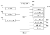
- FIGS. 8 and 9 are block diagrams and flow charts for explaining the control structure of the movable limb compression circulator according to an embodiment of the present invention.
- FIG. 10 is a photograph of a state of use for explaining the contents of simultaneous wearing of the movable limb compression circulator according to an embodiment of the present invention on the left and right sides of the leg.
- FIG. 11 is a photograph of a use state for explaining the contents of various output units of the movable limb compression circulator according to an embodiment of the present invention.
- FIG. 12 is a photograph of a usage state for explaining contents of setting various input modes using an input unit of a movable limb compression circulator according to an embodiment of the present invention.
- FIG. 1 is a three-dimensional view for explaining the appearance of a casing provided as the front and rear portions of a movable limb compression circulation device according to a preferred embodiment of the present invention
- Figure 2 is a mobile type according to a preferred embodiment of the present invention
- Figures 3 and 4 illustrate the coupling relationship of the first and second adapters disposed at one end of the movable limb compression circulation device casing according to an embodiment of the present invention
- Figure 5 is a photograph for explaining the air cuff of the movable limb compression circulation device according to a preferred embodiment of the present invention
- Figures 6 and 7 are movable limbs according to a preferred embodiment of the present invention
- FIG. 8 and 9 are block diagrams and flow charts for explaining the control structure of the movable limb compression circulation device according to a preferred embodiment of the present invention.
- FIG. 10 is a photograph of a use state for explaining the contents of simultaneous wearing of the movable limb compression circulator according to an embodiment of the present invention on the left and right sides of the leg
- FIG. 11 is a movable type according to a preferred embodiment of the present invention
- FIG. 12 is a view illustrating the contents of setting various input modes using the input unit of the movable limb compression circulation device according to an embodiment of the present invention. This is a picture of the usage condition.
- the front part 101 and the rear part 102 are detachably coupled to each other to form the appearance of the device, and on one side of the front part 101
- a power receiving unit 104 is disposed at the lower end of the inner side where the front unit 101 and the rear unit 102 are combined, and a connection line is provided to the power receiving unit 104.
- a wire guide portion 105 is provided from the side to the inward direction, and a casing 100 in which the air generating receiving portion 106 is formed is provided at a position directly above the power receiving portion 104.
- a power supply unit 200 disposed to be accommodated and seated in the power receiving unit 104 is provided.
- the power supply unit 200 is preferably provided with a rechargeable battery to be used when moving, and is to be charged through the wire guide unit 105.
- an air pressurizing unit 300 seated in the air generating accommodating unit 106 is provided so as to be driven by the power of the power supply unit 200.
- the air pressurizing unit 300 may be provided as one of an air blower, an air fan, or a small compressor driven by a motor, but when provided as an air compressor, it is recommended that the air pressurization unit 300 be provided as an oilless compressor that is harmless to the human body. I did it.
- the air pressurizing unit 300 is disposed on both sides of the air generating accommodating unit 106 to send the generated air
- the first air hose unit 400 is provided with one end in communication with the air pressurizing unit 300 It is connected to the other end of the first air hose 400 by a hose, and a plurality of second air hose parts 410 are provided to blow the air generated by the air pressurizing part 300.
- the air pressurization unit 300 may start with a single air hose and branch into a plurality of air hoses. Unlike this, a plurality of air hoses from the air pressurization unit 300 It may be equipped with.
- an opening/closing means 411 is provided in the middle of either or both of the first air hose part 400 or the second air hose part 410 to turn on/off the flow of air.
- the second air hose unit 410 is disposed on one side of the casing 100 in parallel with the direction of the blowing of the second air hose unit 410 so that the inside and the outside of the gate 100 communicate.
- a first adapter 501 and a second adapter 502 are provided to communicate with the air hose unit 410 by inserting and fastening into the first adapter 501 to communicate with each other by a hose, and the second adapter 502
- An air outlet 500 is provided in which the combined air outlet 503 is formed.
- An air cuff that includes a plurality of air pressing parts 602 connected to an air hose 601 provided to be detachable as shown in FIGS. 4 and 5 in the air outlet 503 thus provided ( 600) is provided so that the wearer can massage or press.
- the control unit 700 is provided to control the power supply unit 200 and the opening/closing means 411 and to output information to the output unit 704 accommodated in the input/output receiving groove 103.
- the air cuff 600 is further provided with a human body attachment means 603 on one surface as shown in FIG. 5, and the human body attachment means 603 may be provided with Velcro as an example.
- the air outlet 500 is provided so that the first adapter 501 and the second adapter 502 are inserted and coupled to each other only in the forward direction, so that air leakage due to user carelessness This is to prevent them in advance.
- the air outlet 503 and the air hose 601 of the second adapter 502 are coupled using an O (O) ring, and between the air outlet 503 and the air hose 601 It is also to prevent air leakage.
- O O
- the air pressing unit 602 is provided with a central pressing unit 602a and a peripheral pressing unit 602b disposed outside the central pressing unit 602a. Both ends of 602b) are provided as external curved portions 602c to be curved in an external direction so as to further deviate from the center line, and the material is made of PVC, so that pressure is effectively made and contamination prevention and cleaning are facilitated.
- the air compression unit 602 is provided so that the compression space unit 604 becomes larger and larger while proceeding from the center position to the outside with respect to the central compression unit 602a and forming a V-shaped (V) shape.
- the air cuff 600 is provided so as to effectively press the area to be worn as shown in FIG. 10 and to fit in any direction left and right.
- control unit 700 is provided to sequentially press the air pressing unit 602 one by one using the pressure information collected by the pressure sensing unit 703.
- control unit 700 is provided to control the pressure of the air pressing unit 602 by opening and closing the opening/closing means 411 and driving the air pressing unit 300 so that pressing and releasing can be simultaneously implemented. There is.
- control unit 700 outputs a beep sound through the output unit 704 when the pressure information collected by the pressure detection unit 702 is greater than a preset pressure value, and the air pressurization unit 300 Is provided to drive the air pressurizing unit 300 again when the measured pressure value returns to within a preset value, but the preset pressure value is stepwise according to the setting mode as shown in FIG. It is provided to enable adjustment.
- a movable limb compression circulator of the present invention Using the movable limb compression circulator of the present invention described above, it is possible to use the limb compression circulator regardless of place through a compact and lightweight body and a rechargeable power supply device, and at the same time, the user can wear it and use it while moving.
- the air is branched by providing a plurality of second air hoses that are connected to the other end of the first air hose that is connected to one end of the air pressurization unit to send the air generated by the air pressurization unit to branch the air generated by the air pressurization unit and blow it to the air cuff
- Air leakage is prevented by connecting the air outlet of the second adapter and the air hose using O-rings to prevent air leakage, and the air compression unit is provided with a symmetrical shape and a body attachment means is provided on one side.
- a pressure sensing unit is provided in the air hose, so that the pressure of each air compression unit can be sensed and controlled separately to increase the massage effect, and the pressure of the air compression unit is collected, and air is compressed by opening and closing the driving and opening means of the air pressing unit Negative pressure can be automatically raised or lowered, and if the pressure information collected by the pressure sensing unit is greater than the preset pressure value, a beep sound is output through the output unit and the operation of the air pressure unit is stopped to prevent accidents in use.
- the air pressurization unit is driven again to perform normal operation without user intervention, and the second adapters coupled to the first adapter and communicated with each other are in a forward direction. It is effective to prevent air leakage due to user's carelessness by being combined only.
Landscapes
- Health & Medical Sciences (AREA)
- Epidemiology (AREA)
- Pain & Pain Management (AREA)
- Physical Education & Sports Medicine (AREA)
- Rehabilitation Therapy (AREA)
- Life Sciences & Earth Sciences (AREA)
- Animal Behavior & Ethology (AREA)
- General Health & Medical Sciences (AREA)
- Public Health (AREA)
- Veterinary Medicine (AREA)
- Massaging Devices (AREA)
Abstract
Description
도 2 은 본 발명의 바람직한 일실시예에 따른 이동형 사지 압박 순환장치 케이싱의 내부 배치를 위한 3차원 도면이다.
도 1 은 본 발명의 바람직한 일실시예에 따른 이동형 사지 압박 순환장치의 전면부와 후면부로 구비되는 케이싱의 외형을 설명하기 위한 3차원 도면이고, 도 2 은 본 발명의 바람직한 일실시예에 따른 이동형 사지 압박 순환장치 케이싱의 내부 배치를 위한 3차원 도면이며, 도 3 및 4 는 본 발명의 바람직한 일실시예에 따른 이동형 사지 압박 순환장치 케이싱의 일단에 배치되는 제 1,2 어댑터부의 결합 관계를 설명하기 위한 3차원 도면이고, 도 5 은 본 발명의 바람직한 일실시예에 따른 이동형 사지 압박 순환장치의 에어 커프를 설명하기 위한 사진이며, 도 6 및 7 은 본 발명의 바람직한 일실시예에 따른 이동형 사지 압박 순환장치의 에어 가압부와 제 1,2 에어 호스부를 설명하기 위한 개념도이며, 도 8 및 9 는 본 발명의 바람직한 일실시예에 따른 이동형 사지 압박 순환장치의 제어 구조를 설명하기 위한 블록도와 순서도이고, 도 10 은 본 발명의 바람직한 일실시예에 따른 이동형 사지 압박 순환장치를 다리의 좌 우에 동시 착용되는 내용을 설명하기 위한 사용 상태 사진이며, 도 11 은 본 발명의 바람직한 일실시예에 따른 이동형 사지 압박 순환장치의 다양한 출력부 내용을 설명하기 위한 사용 상태 사진이며, 도 12 는 본 발명의 바람직한 일실시예에 따른 이동형 사지 압박 순환장치의 입력부를 이용하여 다양한 입력 모드를 설정하는 내용을 설명하기 위한 사용 상태 사진이다.
한편, 상기 제 1 에어 호스부(400) 또는 상기 제 2 에어 호스부(410)의 어느 하나 또는 모두의 중간에는 개폐 수단(411)이 구비되어 송풍의 흐름을 ON/OFF하도록 한다.
Claims (10)
- 전면부(101)와 후면부(102)가 서로 착탈 결합 되어 장치의 외형을 이루며 상기 전면부(101)의 일면에는 입출력 수용홈(103)이 구비되는 상기 전면부(101)와 상기 후면부(102)가 결합된 내측의 하단 위치에는 전원 수용부(104)가 배치되고 상기 전원 수용부(104)에 연결선이 입출 되도록 측면에서 내측 방향으로 전선 가이드부(105)가 구비되며 상기 전원 수용부(104)의 직상 위치에는 에어 발생 수용부(106)가 구비되는 케이싱(100);상기 전원 수용부(104)에 수용되어 안착되도록 구비되는 전원 공급부(200);상기 전원 공급부(200)의 전원으로 구동되도록 상기 에어 발생 수용부(106)에 안착되게 구비되는 에어 가압부(300);상기 에어 가압부(300)가 발생한 공기를 보내도록 상기 에어 발생 수용부(106)의 양측에 배치되되 상기 에어 가압부(300)에 일단이 연통되도록 구비되는 제 1 에어 호스부(400);상기 제 1 에어 호스(400)부의 타단에 호스로 연결되어 상기 에어 가압부(300)가 발생한 공기를 송풍하도록 복수 개가 구비되는 제 2 에어 호스부(410);상기 제 1 에어 호스부(400) 또는 상기 제 2 에어 호스부(410)의 어느 하나 또는 모두의 중간에 구비되는 개폐 수단(411);상기 케이싱(100)의 내 외부가 연통 되도록 상기 제 2 에어 호스부(410)의 송풍 진행 방향과 나란하게 상기 케이싱(100)의 일측면에 배치되어 상기 제 2 에어 호스부(410)에 호스로 각각 연통 되도록 제 1 어댑터(501)와 상기 제 1 어댑터(501)에 삽입 체결되어 연통 되도록 제 2 어댑터(502)가 구비되되 상기 제 2 어댑터(502)에 결합되는 에어 유출입구(503)가 구비되는 에어 유출입부(500);상기 에어 유출입구(503)에 탈 부착이 가능하도록 구비되는 에어 호스(601)에 연결되는 복수의 에어 압박부(602)가 구비되는 에어 커프(600); 및상기 입출력 수용홈(103)에 수용되는 입력부(701)의 입력 정보와 내부의 타이머(702) 또는 압력 감지부(703)가 수집한 정보를 이용하여 상기 전원 공급부(200)와 상기 개폐 수단(411)을 제어하며 상기 입출력 수용홈(103)에 수용되는 출력부(704)에 정보를 출력하도록 구비되는 제어부(700); 를 포함하는 이동형 사지 압박 순환장치.
- 제 1 항에 있어서,상기 에어 커프(600)는,인체 부착수단(603)이 일면에 더 구비되는 것을 특징으로 하는 이동형 사지 압박 순환장치.
- 제 1 항에 있어서,상기 에어 유출입부(500)는,상기 제 1 어댑터(501)와 상기 제 2 어댑터(502)는 서로 정방향으로만 삽입되어 결합 되도록 구비되는 것을 특징으로 하는 이동형 사지 압박 순환장치.
- 제 1 항에 있어서,상기 제 2 어댑터(502)의 상기 에어 유출입구(503)와 상기 에어 호스(601)는 오( O ) 링을 이용하여 결합되는 것을 특징으로 하는 이동형 사지 압박 순환장치.
- 제 1 항에 있어서,상기 에어 압박부(602)는,중심 압박부(602a)와 상기 중심 압박부(602a)의 외부에 배치되는 주위 압박부(602b)로 구비되되 상기 주위 압박부(602b)의 양단은 중심선 밖으로 더 벗어나도록 외부 방향으로 만곡지게 외부 만곡부(602c)로 구비되며 PVC 재질로 구비되는 것을 특징으로 하는 이동형 사지 압박 순환장치.
- 제 5 항에 있어서,상기 에어 압박부(602)는,상기 중심 압박부(602a)를 기준으로 중심 위치에서 외부로 진행하면서 서로 브이자 ( V ) 형태를 이루어 압박 공간부(604)가 점점 더 넓어지도록 구비되는 것을 특징으로 하는 이동형 사지 압박 순환장치.
- 제 5 항에 있어서,상기 에어 커프(600)는,좌우 어느 방향으로도 착용 될 수 있도록 구비되는 것을 특징으로 하는 이동형 사지 압박 순환장치.
- 제 5 항에 있어서,상기 제어부(700)는,상기 압력 감지부(703)가 수집한 압력 정보를 이용하여 상기 에어 압박부(602)를 하나씩 순차적으로 압박하도록 구비되는 것을 특징으로 하는 이동형 사지 압박 순환장치.
- 제 8 항에 있어서,상기 제어부(700)는,상기 에어 가압부(300)의 구동과 상기 개폐 수단(411)을 개폐함으로써 상기 에어 압박부(602)의 압력을 각각 제어하도록 구비되는 것을 특징으로 하는 이동형 사지 압박 순환장치.
- 제 1 항에 있어서,상기 제어부(700)는,상기 압력 감지부(702)가 수집한 압력 정보가 사전에 설정된 압력 값 보다 큰 경우는 상기 출력부(704)를 통해 비프음을 출력하고 상기 에어 가압부(300)의 동작을 정지하되, 측정되는 압력 값이 사전 설정치 이내로 되돌아오는 경우에 상기 에어 가압부(300)를 다시 구동하도록 구비되되 사전에 설정된 압력 값은 설정 모드에 따라 단계별 조정이 가능하도록 구비되는 것을 특징으로 하는 이동형 사지 압박 순환장치.
Priority Applications (3)
| Application Number | Priority Date | Filing Date | Title |
|---|---|---|---|
| JP2022501106A JP7276949B2 (ja) | 2019-03-11 | 2020-03-02 | 移動型四肢圧迫循環装置 |
| CN202080020869.6A CN113660920B (zh) | 2019-03-11 | 2020-03-02 | 移动式四肢压迫循环装置 |
| US17/438,748 US20220339057A1 (en) | 2019-03-11 | 2020-03-02 | Mobile limb compression and circulation apparatus |
Applications Claiming Priority (2)
| Application Number | Priority Date | Filing Date | Title |
|---|---|---|---|
| KR10-2019-0027586 | 2019-03-11 | ||
| KR1020190027586A KR102179175B1 (ko) | 2019-03-11 | 2019-03-11 | 이동형 사지 압박 순환장치 |
Publications (1)
| Publication Number | Publication Date |
|---|---|
| WO2020184880A1 true WO2020184880A1 (ko) | 2020-09-17 |
Family
ID=72428032
Family Applications (1)
| Application Number | Title | Priority Date | Filing Date |
|---|---|---|---|
| PCT/KR2020/002946 Ceased WO2020184880A1 (ko) | 2019-03-11 | 2020-03-02 | 이동형 사지 압박 순환장치 |
Country Status (5)
| Country | Link |
|---|---|
| US (1) | US20220339057A1 (ko) |
| JP (1) | JP7276949B2 (ko) |
| KR (1) | KR102179175B1 (ko) |
| CN (1) | CN113660920B (ko) |
| WO (1) | WO2020184880A1 (ko) |
Cited By (2)
| Publication number | Priority date | Publication date | Assignee | Title |
|---|---|---|---|---|
| CN115531155A (zh) * | 2021-06-29 | 2022-12-30 | 株式会社阳光医疗 | 移动式四肢压迫循环装置 |
| JP2023003862A (ja) * | 2021-06-24 | 2023-01-17 | サンメディックス カンパニー,リミテッド | 移動型四肢圧迫循環装置 |
Families Citing this family (2)
| Publication number | Priority date | Publication date | Assignee | Title |
|---|---|---|---|---|
| KR102602079B1 (ko) * | 2022-08-18 | 2023-11-16 | 김대균 | 다기능 사지압박순환장치 |
| KR102792613B1 (ko) | 2022-12-14 | 2025-04-09 | (주)선메딕스 | 웨어러블 생체신호 감지 이동형 사지압박순환장치 |
Citations (5)
| Publication number | Priority date | Publication date | Assignee | Title |
|---|---|---|---|---|
| JP2000254187A (ja) * | 1999-01-08 | 2000-09-19 | Matsushita Electric Works Ltd | 足用エアーマッサージ器 |
| JP2003319989A (ja) * | 2002-05-07 | 2003-11-11 | Marutaka Co Ltd | 腕用エアマッサージ機 |
| KR200369187Y1 (ko) * | 2004-09-01 | 2004-12-03 | 권영식 | 사지 압박 순환장치 |
| KR101545096B1 (ko) * | 2014-08-29 | 2015-08-21 | (주)닥터서플라이 | 공압을 이용한 휴대용 마사지 장치 |
| KR101778983B1 (ko) * | 2017-06-16 | 2017-09-15 | 주식회사 뷰엘리스 | 공기압 마사지용 다리커프 |
Family Cites Families (39)
| Publication number | Priority date | Publication date | Assignee | Title |
|---|---|---|---|---|
| JP2607226Y2 (ja) * | 1993-12-17 | 2001-05-28 | 株式会社フジ医療器 | 加圧式マッサージャー |
| JP4373551B2 (ja) * | 1999-12-02 | 2009-11-25 | 株式会社マルタカ | エアマッサージ器 |
| KR20020037575A (ko) * | 2000-11-14 | 2002-05-22 | 박홍신 | 고무풍선 이용 건강기구. |
| CN2499023Y (zh) * | 2000-11-27 | 2002-07-10 | 王润明 | 兼具按摩及提臀功能的健康短裤 |
| JP2002200132A (ja) | 2000-12-28 | 2002-07-16 | Toshiba Tec Corp | エア式マッサージ装置のエア供給装置 |
| US7490620B2 (en) * | 2004-02-23 | 2009-02-17 | Tyco Healthcare Group Lp | Fluid conduit connector apparatus |
| GB0601451D0 (en) * | 2006-01-24 | 2006-03-08 | Bristol Myers Squibb Co | Control unit assembly |
| US7618384B2 (en) | 2006-09-20 | 2009-11-17 | Tyco Healthcare Group Lp | Compression device, system and method of use |
| JP4131873B2 (ja) * | 2006-09-29 | 2008-08-13 | 社会福祉法人富山県社会福祉総合センター | 身体補装具 |
| US8603150B2 (en) * | 2006-12-04 | 2013-12-10 | Carefusion 2200, Inc. | Methods and apparatus for adjusting blood circulation |
| US9642759B2 (en) * | 2007-04-13 | 2017-05-09 | Stryker Corporation | Patient support with universal energy supply system |
| US8092409B2 (en) * | 2007-05-18 | 2012-01-10 | Tyco Healthcare Group Lp | Reinforced connector |
| US8535253B2 (en) * | 2008-09-30 | 2013-09-17 | Covidien Lp | Tubeless compression device |
| WO2010065644A2 (en) * | 2008-12-02 | 2010-06-10 | Eddy Patrick E | Compression device and control system for applying pressure to a limb of a living being |
| CN201558270U (zh) * | 2009-07-03 | 2010-08-25 | 胡云成 | 男性按摩器 |
| US8858475B2 (en) | 2010-10-12 | 2014-10-14 | Venous Health Systems, Inc. | Apparatus, systems, and methods for augmenting the flow of fluid within body vessels |
| US20120209153A1 (en) * | 2011-02-14 | 2012-08-16 | Farrow Mark A | Deep vein thrombosis therapy device |
| US10512587B2 (en) * | 2011-07-27 | 2019-12-24 | Thermotek, Inc. | Method and apparatus for scalp thermal treatment |
| US9326911B2 (en) * | 2012-09-14 | 2016-05-03 | Recovery Force, LLC | Compression integument |
| US9168197B2 (en) * | 2012-09-28 | 2015-10-27 | Covidien Lp | Vascular compression system |
| KR200472269Y1 (ko) | 2012-10-30 | 2014-04-15 | 주식회사 웰뷰텍 | 공기 마사지기용 에어커프 |
| US9668932B2 (en) * | 2013-03-15 | 2017-06-06 | Compression Therapy Concepts, Inc. | Portable micro air pump for use in intermittent pneumatic compression therapy |
| US10058475B2 (en) * | 2013-03-15 | 2018-08-28 | Innovamed Health, LLC | Portable intermittent pneumatic compression system |
| US20150094629A1 (en) * | 2013-09-27 | 2015-04-02 | Covidien Lp | Compression garment controlling |
| US20150105706A1 (en) * | 2013-10-10 | 2015-04-16 | Reizel Polak | Method for calming a person |
| KR101630921B1 (ko) * | 2013-11-20 | 2016-06-16 | (주)대성마리프 | 공기 압박 커프 |
| CN204158699U (zh) * | 2014-04-09 | 2015-02-18 | 合肥达米医疗科技有限公司 | 一种便携式下肢血栓预防仪 |
| US20170007494A1 (en) * | 2014-09-22 | 2017-01-12 | Respiratory Technologies, Inc. | Hfcc therapy system providing patient interventions for improved adherence |
| CN106176164A (zh) * | 2016-07-29 | 2016-12-07 | 南京恒慧智能科技有限公司 | 一种静脉曲张治疗仪 |
| CN106264472A (zh) * | 2016-09-28 | 2017-01-04 | 中国科学院重庆绿色智能技术研究院 | 一种基于石墨烯柔性压力传感器的脉诊仪 |
| CN108078750A (zh) * | 2016-11-22 | 2018-05-29 | 因诺万麦德健康公司 | 便携式间歇气动系统 |
| CN107252140A (zh) * | 2017-07-27 | 2017-10-17 | 浙江圣麦斯针织有限公司 | 智能压力报警袜 |
| CN208355733U (zh) * | 2017-08-10 | 2019-01-11 | 重庆医科大学附属第一医院 | 一种医疗护理用无线肢体按摩器 |
| US10434033B2 (en) * | 2017-11-01 | 2019-10-08 | Vena Group, LLC | Portable, reusable, and disposable intermittent pneumatic compression system |
| CN108743287A (zh) * | 2018-08-23 | 2018-11-06 | 南通科威瀚医疗科技有限公司 | 一种穿戴式梯度压力抗栓装置 |
| US11638675B2 (en) * | 2018-11-07 | 2023-05-02 | Zenith Technical Innovations, Llc | System and method for heat or cold therapy and compression therapy |
| US11304869B2 (en) * | 2019-02-13 | 2022-04-19 | Bio Compression Systems, Inc. | Portable system for the prophylaxis of deep vein thrombosis |
| US10874578B2 (en) * | 2019-02-14 | 2020-12-29 | John A. Bennett | Inflation garment having a portable controller for treatment of DVT |
| US11559460B2 (en) * | 2019-02-28 | 2023-01-24 | Gary Chiu | Compression device |
-
2019
- 2019-03-11 KR KR1020190027586A patent/KR102179175B1/ko active Active
-
2020
- 2020-03-02 WO PCT/KR2020/002946 patent/WO2020184880A1/ko not_active Ceased
- 2020-03-02 JP JP2022501106A patent/JP7276949B2/ja active Active
- 2020-03-02 US US17/438,748 patent/US20220339057A1/en not_active Abandoned
- 2020-03-02 CN CN202080020869.6A patent/CN113660920B/zh active Active
Patent Citations (5)
| Publication number | Priority date | Publication date | Assignee | Title |
|---|---|---|---|---|
| JP2000254187A (ja) * | 1999-01-08 | 2000-09-19 | Matsushita Electric Works Ltd | 足用エアーマッサージ器 |
| JP2003319989A (ja) * | 2002-05-07 | 2003-11-11 | Marutaka Co Ltd | 腕用エアマッサージ機 |
| KR200369187Y1 (ko) * | 2004-09-01 | 2004-12-03 | 권영식 | 사지 압박 순환장치 |
| KR101545096B1 (ko) * | 2014-08-29 | 2015-08-21 | (주)닥터서플라이 | 공압을 이용한 휴대용 마사지 장치 |
| KR101778983B1 (ko) * | 2017-06-16 | 2017-09-15 | 주식회사 뷰엘리스 | 공기압 마사지용 다리커프 |
Cited By (2)
| Publication number | Priority date | Publication date | Assignee | Title |
|---|---|---|---|---|
| JP2023003862A (ja) * | 2021-06-24 | 2023-01-17 | サンメディックス カンパニー,リミテッド | 移動型四肢圧迫循環装置 |
| CN115531155A (zh) * | 2021-06-29 | 2022-12-30 | 株式会社阳光医疗 | 移动式四肢压迫循环装置 |
Also Published As
| Publication number | Publication date |
|---|---|
| KR20200108653A (ko) | 2020-09-21 |
| US20220339057A1 (en) | 2022-10-27 |
| KR102179175B1 (ko) | 2020-11-16 |
| CN113660920B (zh) | 2023-12-01 |
| CN113660920A (zh) | 2021-11-16 |
| JP2022524661A (ja) | 2022-05-09 |
| JP7276949B2 (ja) | 2023-05-18 |
Similar Documents
| Publication | Publication Date | Title |
|---|---|---|
| WO2020184880A1 (ko) | 이동형 사지 압박 순환장치 | |
| US7147610B2 (en) | Multiple combination heat/massage devices | |
| KR100961581B1 (ko) | 사지압박 공기 마사지기와 부항기 병용 장치 | |
| JP2009247906A (ja) | 美顔マッサージマスク | |
| WO2022177108A1 (ko) | 발달장애아동용 압박조끼 | |
| WO2016167617A1 (ko) | 안마 매트리스 | |
| WO2016167613A1 (ko) | 안마 베개 | |
| WO2020149532A2 (ko) | 눈 및 코 복합 마사지기 | |
| WO2012124912A2 (ko) | 휴대용 무릎 관절 재활 운동 기구 | |
| WO2015093753A1 (ko) | 신체 접촉 휴대용 치료기 | |
| WO2016080579A1 (ko) | 진동마사지 기능이 마련된 에어커프 및 그에 사용되는 진동지압 발판 | |
| CN108743283A (zh) | 一种用于上肢康复训练及保护的穿戴式气囊装置 | |
| WO2015064884A1 (ko) | 자기장 프로브의 구동 궤적 및 패턴 조작이 가능한 베드형 자기장 치료 장치 | |
| CN114404229B (zh) | 一种用于下肢康复的柔性可穿戴物执行器 | |
| CN110693691A (zh) | 基于神经靶向调控的肢体远端神经修复系统及其实现方法 | |
| WO2019156450A1 (ko) | 전신스트레칭 온열 안마매트 및 구동방법 | |
| WO2023095976A1 (ko) | 턱관절에 대한 온찜질 기능을 갖는 인체 자극기기 및 전기식 찜질기 | |
| US20220409474A1 (en) | Movable limb compression and circulation apparatus | |
| WO2013035926A1 (ko) | 다한증 전기치료기 | |
| CN209203993U (zh) | 一种预防术后便秘的治疗仪 | |
| WO2018230930A1 (ko) | 공기압 마사지용 다리커프 | |
| WO2015016396A1 (ko) | 가슴 확대 및 성형을 위한 장치 | |
| CN114869257A (zh) | 一种用于神经外科患者术后康复的智能穿戴设备 | |
| WO2001037776A1 (en) | A negative pressure treatment equipment | |
| JP2023003862A (ja) | 移動型四肢圧迫循環装置 |
Legal Events
| Date | Code | Title | Description |
|---|---|---|---|
| 121 | Ep: the epo has been informed by wipo that ep was designated in this application |
Ref document number: 20769236 Country of ref document: EP Kind code of ref document: A1 |
|
| ENP | Entry into the national phase |
Ref document number: 2022501106 Country of ref document: JP Kind code of ref document: A |
|
| NENP | Non-entry into the national phase |
Ref country code: DE |
|
| 122 | Ep: pct application non-entry in european phase |
Ref document number: 20769236 Country of ref document: EP Kind code of ref document: A1 |
|
| 122 | Ep: pct application non-entry in european phase |
Ref document number: 20769236 Country of ref document: EP Kind code of ref document: A1 |