WO2020184488A1 - 気液分離装置 - Google Patents
気液分離装置 Download PDFInfo
- Publication number
- WO2020184488A1 WO2020184488A1 PCT/JP2020/009872 JP2020009872W WO2020184488A1 WO 2020184488 A1 WO2020184488 A1 WO 2020184488A1 JP 2020009872 W JP2020009872 W JP 2020009872W WO 2020184488 A1 WO2020184488 A1 WO 2020184488A1
- Authority
- WO
- WIPO (PCT)
- Prior art keywords
- gas
- liquid
- phase
- shaped groove
- groove forming
- Prior art date
- Legal status (The legal status is an assumption and is not a legal conclusion. Google has not performed a legal analysis and makes no representation as to the accuracy of the status listed.)
- Ceased
Links
Images


Classifications
-
- F—MECHANICAL ENGINEERING; LIGHTING; HEATING; WEAPONS; BLASTING
- F02—COMBUSTION ENGINES; HOT-GAS OR COMBUSTION-PRODUCT ENGINE PLANTS
- F02M—SUPPLYING COMBUSTION ENGINES IN GENERAL WITH COMBUSTIBLE MIXTURES OR CONSTITUENTS THEREOF
- F02M37/00—Apparatus or systems for feeding liquid fuel from storage containers to carburettors or fuel-injection apparatus; Arrangements for purifying liquid fuel specially adapted for, or arranged on, internal-combustion engines
- F02M37/20—Apparatus or systems for feeding liquid fuel from storage containers to carburettors or fuel-injection apparatus; Arrangements for purifying liquid fuel specially adapted for, or arranged on, internal-combustion engines characterised by means for preventing vapour lock
-
- F—MECHANICAL ENGINEERING; LIGHTING; HEATING; WEAPONS; BLASTING
- F25—REFRIGERATION OR COOLING; COMBINED HEATING AND REFRIGERATION SYSTEMS; HEAT PUMP SYSTEMS; MANUFACTURE OR STORAGE OF ICE; LIQUEFACTION SOLIDIFICATION OF GASES
- F25B—REFRIGERATION MACHINES, PLANTS OR SYSTEMS; COMBINED HEATING AND REFRIGERATION SYSTEMS; HEAT PUMP SYSTEMS
- F25B43/00—Arrangements for separating or purifying gases or liquids; Arrangements for vaporising the residuum of liquid refrigerant, e.g. by heat
-
- H—ELECTRICITY
- H01—ELECTRIC ELEMENTS
- H01M—PROCESSES OR MEANS, e.g. BATTERIES, FOR THE DIRECT CONVERSION OF CHEMICAL ENERGY INTO ELECTRICAL ENERGY
- H01M8/00—Fuel cells; Manufacture thereof
- H01M8/04—Auxiliary arrangements, e.g. for control of pressure or for circulation of fluids
-
- Y—GENERAL TAGGING OF NEW TECHNOLOGICAL DEVELOPMENTS; GENERAL TAGGING OF CROSS-SECTIONAL TECHNOLOGIES SPANNING OVER SEVERAL SECTIONS OF THE IPC; TECHNICAL SUBJECTS COVERED BY FORMER USPC CROSS-REFERENCE ART COLLECTIONS [XRACs] AND DIGESTS
- Y02—TECHNOLOGIES OR APPLICATIONS FOR MITIGATION OR ADAPTATION AGAINST CLIMATE CHANGE
- Y02E—REDUCTION OF GREENHOUSE GAS [GHG] EMISSIONS, RELATED TO ENERGY GENERATION, TRANSMISSION OR DISTRIBUTION
- Y02E60/00—Enabling technologies; Technologies with a potential or indirect contribution to GHG emissions mitigation
- Y02E60/30—Hydrogen technology
- Y02E60/50—Fuel cells
Definitions
- a gas-liquid separation device that separates a gas-liquid two-phase flow into a gas phase and a liquid phase
- a gas-liquid two-phase flow is flowed in from above, the separated gas phase is discharged upward, and the separated liquid phase is discharged.
- a device for discharging downwards see, for example, Patent Document 1.
- a gas-liquid two-phase flow is introduced into the housing to separate the gas phase and the liquid phase by surface tension, the gas phase is discharged upward, and the liquid phase is downward. It was a device to discharge.
- gas-liquid separators have come to be installed in vehicles such as vehicles.
- vehicles such as vehicles vibrate or tilt as they move, the surface tension cannot function sufficiently, and it may be difficult to accurately separate the gas phase and the liquid phase. is assumed.
- the present invention has been made in view of the above points, and an object of the present invention is to be able to accurately separate a gas phase and a liquid phase even when the invention is vibrated or tilted.
- the purpose is to provide a liquid separation device.
- the feature of the gas-liquid separator according to the present invention is With the housing A first opening into which a gas-liquid two-phase flow is introduced into the housing, A first grooved portion having a first groove extending in the first direction, which is arranged to face the first opening and is introduced into the housing through the first opening. A first grooved portion that contacts the two-phase flow and separates the gas-liquid two-phase flow into a liquid phase and a gas phase by surface tension. A second grooved portion having a second groove extending in a second direction different from the first direction, and is in contact with a gas-liquid two-phase flow that has passed through the first grooved portion. A second grooved portion that separates the gas-liquid two-phase flow into a liquid phase and a gas phase by surface tension.
- the features of the gas-liquid separator according to the present invention A are With a housing (for example, a housing 2100 described later) A first opening into which a gas-liquid two-phase flow is introduced inside the housing (for example, a discharge opening 2240 described later) and The gas-liquid two-phase flow is arranged to face the first opening and comes into contact with the gas-liquid two-phase flow introduced into the inside of the housing from the first opening, and the gas-liquid two-phase flow is combined with the liquid phase by surface tension.
- a grooved portion having a groove to separate into (for example, a front V-shaped groove forming portion 2400 described later) and A second opening different from the first opening, which is formed so that the separated gas phase can be discharged to the outside of the housing (for example, a suction opening 2340 described later) and the like.
- a liquid phase storage unit (for example, drainage guide groove 2810, bottom surface 2120, etc.) that temporarily stores the separated liquid phase, and It is provided with a discharge port (for example, a drain port 2800 described later) formed so that the liquid phase stored in the liquid phase storage unit can be discharged to the outside of the housing.
- the gas-liquid separator according to the present invention A may have the following features.
- the gas-liquid separator according to the present invention A may have the following features.
- a protrusion for example, a protrusion
- the gas-liquid separator according to the present invention A may have the following features.
- a liquid phase inducing portion (for example, a second liquid phase inducing portion 2770B in the gas-liquid separator 2010B) extending downward from the lower end of the first opening is formed in the first opening.
- a first opening into which a gas-liquid two-phase flow is introduced for example, a discharge opening 1240 or a discharge opening 2240, which will be described later
- a first grooved portion having a first groove for example, a groove portion 1402 or a groove portion 2402 described later
- a first direction for example, a vertical direction TB described later
- a first which is arranged facing the opening, comes into contact with the gas-liquid two-phase flow introduced into the housing from the first opening, and separates the gas-liquid two-phase flow into a liquid phase and a gas phase by surface tension.
- Grooved portions for example, right V-shaped groove forming portion 1400 and front V-shaped groove forming portion 2400, which will be described later
- a second grooved portion having a second groove for example, groove portion 1472 or groove portion 2472 described later
- a second direction different from the first direction for example, sharp angle ⁇ 4 described later.
- a second grooved portion (for example, described later) that contacts the gas-liquid two-phase flow that has passed through the first grooved portion and separates the gas-liquid two-phase flow into a liquid phase and a gas phase by surface tension.
- a second opening different from the first opening, which is formed so that the separated gas phase can be discharged to the outside of the housing for example, a suction opening 1340 or a suction opening 2340 described later.
- a liquid phase storage unit (for example, a drainage guide groove portion 1810 or a drainage guide groove portion described later) that is located below the first grooved portion and the second grooved portion and temporarily stores the separated liquid phase. 2810 etc.) and Provided is a gas-liquid separator including a discharge port (for example, a drain port 1800 or a drain port 2800 described later) formed so that the liquid phase stored in the storage unit can be discharged to the outside of the housing.
- the gas-liquid separator according to the first embodiment is A first grooved portion having a first groove extending in the first direction, which is arranged to face the first opening and is introduced into the housing through the first opening.
- a first grooved portion that contacts the two-phase flow and separates the gas-liquid two-phase flow into a liquid phase and a gas phase by surface tension.
- a second grooved portion having a second groove extending in a second direction different from the first direction, and is in contact with a gas-liquid two-phase flow that has passed through the first grooved portion. It is provided with a second grooved portion that separates the gas-liquid two-phase flow into a liquid phase and a gas phase by surface tension.
- the first grooved portion has a first groove extending (extending) in the first direction.
- the first grooved portion comes into contact with the gas-liquid two-phase flow introduced into the housing and separates the gas-liquid two-phase flow into a liquid phase and a gas phase by surface tension.
- the second grooved portion has a second groove extending in a second direction different from the first direction.
- the second grooved portion comes into contact with the gas-liquid two-phase flow that has passed through the first grooved portion and separates the gas-liquid two-phase flow into a liquid phase and a gas phase by surface tension.
- the first groove of the first grooved portion extends in the first direction
- the second groove of the second grooved portion has a second direction different from the first direction. Extends to. Therefore, even if it vibrates or tilts, it is possible to make the surface tension function in at least one of the first groove and the second groove to separate the gas phase and the liquid phase. it can.
- the gas-liquid two-phase flow is separated into a liquid phase and a gas phase by the first grooved portion, and then the gas-liquid two-phase flow passing through the second grooved portion is separated into a liquid phase and a gas phase. Separate into and. Since the surface tension is made to function in two steps in this way, it is possible to accurately separate the gas phase and the liquid phase even when the surface tension is vibrated or tilted.
- the second embodiment is the second embodiment, in the first embodiment.
- the first groove of the first grooved portion extends along a vertical direction, or extends in an acute angle (for example, an acute angle ⁇ 3 described later) with respect to the vertical direction. It is configured to guide the separated liquid phase by its own weight, gas-liquid two-phase flow, or gas phase airflow.
- the liquid phase separated by the first grooved portion is subjected to its own weight or gas. It can be guided downward by a liquid two-phase flow or a gas-phase flow, and the configuration can be simplified.
- the third embodiment is the third embodiment in the first embodiment.
- the groove angles of the first groove and the second groove are configured to be acute (for example, ⁇ shown in FIG. 9 described later).
- the groove angle of the first groove and the groove angle of the second groove may be the same or different.
- the groove angles of the first groove and the second groove are acute, the gas-liquid two-phase flow can be easily brought into contact with the groove, and the gas phase and the liquid phase can be accurately separated.
- the fourth embodiment is the first embodiment.
- the second direction of the second groove is configured to extend toward the liquid phase reservoir.
- the liquid phase separated in the second groove can be guided toward the liquid phase storage unit.
- the fifth embodiment is the first embodiment.
- the second groove of the second grooved portion is formed on the front surface and the back surface of the second grooved portion, and the liquid phase is formed between the second groove on the front surface and the second groove on the back surface. It is configured so that it can flow down to both sides.
- the front surface and the back surface of the second grooved portion can be separated into a liquid phase, and can be efficiently separated.
- the sixth embodiment is the sixth embodiment in the first embodiment.
- the second grooved portion is configured to incline downward toward the liquid phase storage portion.
- the liquid phase separated in the second groove can be guided toward the liquid phase storage unit.
- the seventh embodiment is the first embodiment.
- a first partition (for example, described later) that communicates with the first opening and extends into the housing to introduce a gas-liquid two-phase flow from outside the housing into the housing through the first opening.
- a second partition body (for example, an outlet pipe 1300 described later) that communicates with the second opening and extends into the housing to lead a gas phase from the inside of the housing to the outside of the housing through the second opening. And the outlet pipe 2300, etc.).
- the first partition is a partition for introducing a gas-liquid two-phase flow from the outside of the housing to the inside of the housing through the first opening, and extends into the housing in communication with the first opening.
- the first partition may be a partition capable of introducing a gas-liquid two-phase flow into the housing through the first opening, regardless of the shape and size. In other words, it may be a partition for guiding the gas-liquid two-phase flow outside the housing into the housing.
- the first partition body can have a tubular shape such as a cylinder or a tubular shape. When formed into a tubular or tubular shape, the gas-liquid two-phase flow can flow in the tubular or tubular inner space.
- the first partition has a tubular or tubular shape, it is not necessary that the cross section perpendicular to the axial direction (direction along the central axis or direction along the extending axis) is constant.
- the cross section may gradually widen or narrow.
- the first partition may include a shape extending straight along the axial direction, or a shape that is curved or bent.
- the first partition body does not have to have a shape such as a tubular shape or a tubular shape that all orbits (circulates) around an axis (central axis, extending axis), and has a shape in which a part of the orbit is vacant. It may be. Further, the first partition body may have a plate shape. The first partition body may have a shape composed of one plate or a shape obtained by combining a plurality of plates such as a groove shape.
- the second partition body is a partition for deriving the gas phase from the inside of the housing to the outside of the housing through the second opening, and extends into the housing in communication with the second opening.
- the second partition may be a partition capable of introducing a gas-liquid two-phase flow into the housing through the second opening, regardless of the shape and size. In other words, it may be a partition for guiding the gas-liquid two-phase flow outside the housing into the housing.
- the second partition can have a tubular or tubular shape such as a cylinder. When the second partition has a tubular or tubular shape, it is not necessary that the cross section perpendicular to the axial direction (direction along the central axis or direction along the extending axis) is constant. The cross section may gradually widen or narrow. Further, the second partition may include a shape extending straight along the axial direction, or a shape that is curved or bent.
- the second partition body does not have to have a shape that all orbits (around) around the axis (central axis, extending axis) like a tubular shape or a tubular shape, and a shape in which a part of the orbit is vacant. It may be. Further, the second partition body may have a plate-like shape. The second partition body may have a shape composed of one plate or a shape obtained by combining a plurality of plates such as a groove shape.
- the gas-liquid two-phase flow can be accurately introduced from the outside of the housing into the housing, and the gas phase can be accurately derived from the inside of the housing to the outside of the housing.
- the eighth embodiment is the seventh embodiment.
- the second grooved portion is A first lower grooved portion (for example, a right side inclined V-shaped groove forming portion 1470 described later) arranged below the first partition body and It has a second lower grooved portion (for example, a left inclined V-shaped groove forming portion 1670 described later) which is separated from the first lower grooved portion and is arranged below the second partition body.
- the first lower grooved portion and the second lower grooved portion are configured to incline downward toward the liquid phase storage portion.
- the gas-liquid two-phase flow can be efficiently separated into a liquid phase and a gas phase by the first lower grooved portion and the second lower grooved portion.
- the ninth embodiment is the eighth embodiment.
- the first lower grooved portion is configured to cover the second lower grooved portion above the liquid phase storage portion.
- the gas-liquid two-phase flow that has passed through the first lower grooved portion can be accurately guided to the second lower grooved portion, and an opportunity to separate the gas phase and the liquid phase is provided. Can be increased.
- the tenth embodiment is the seventh embodiment.
- the first partition body and the second partition body have a cylindrical shape and have a cylindrical shape.
- the first partition and the second partition are arranged parallel to each other in the horizontal direction.
- the uppermost portion of the first partition body, the uppermost portion of the second partition body, and the uppermost portion of the first grooved portion are configured to be at the same position.
- the first partition body and the second partition body are positioned at the uppermost part, so that the liquid phase can be accurately flowed down.
- the eleventh embodiment is the eleventh embodiment in the first embodiment. It is configured to have a storage space (for example, a right lower space 1460, a left lower space 1660, a lower space 2460, etc., which will be described later) below the second grooved portion.
- a storage space for example, a right lower space 1460, a left lower space 1660, a lower space 2460, etc., which will be described later.
- the twelfth embodiment is the first embodiment.
- the first grooved portion and the second grooved portion are integrally formed. It is configured to have an opening between the first grooved portion and the second grooved portion.
- the thirteenth embodiment is the thirteenth embodiment in the first embodiment.
- the first grooved portion, the second grooved portion, and the housing are integrally formed.
- the fourteenth embodiment is the tenth embodiment.
- the first opening is the cylindrical side surface of the first partition body (for example, the cylindrical side surface 1210 of the gas-liquid separation device 1010 according to the first embodiment described later) or the cylindrical bottom portion of the first partition body (for example, the cylindrical bottom portion of the first partition body).
- it is configured to be formed in the discharge opening 2240 of the gas-liquid separation device 2010 according to the second embodiment described later.
- the bottom of the cylinder is a portion corresponding to the bottom surface of the cylinder, the first partition has a cylindrical shape, and the bottom of the cylinder has a circular shape.
- the fifteenth embodiment is the tenth embodiment.
- the second opening is formed on the cylindrical side surface of the second partition body (for example, the cylindrical side surface 1310 described later) or the cylindrical bottom portion of the second partition body (for example, the suction opening 2340 described later). It is configured as follows.
- the gas phase can be accurately derived from the inside of the housing to the outside of the housing.
- Horizontal (horizontal) HD is a direction that intersects at right angles to the gravity of the earth.
- VD Vertical direction (vertical direction) VD>
- the vertical (vertical) VD is a direction parallel to the gravity of the earth.
- the front-rear direction FR is a direction perpendicular to the front surface portion 1130 and the back surface portion 1140 of the housing 1100 described later (direction along the arrow FR in FIG. 1).
- the front-rear direction FR is parallel to the top surface portion 1110 and the bottom surface portion 1120, and is also a direction parallel to the right side surface portion 1150 and the left side surface portion 1160.
- the front-rear direction FR is a direction perpendicular to the front surface portion 2130 and the back surface portion 2140 of the housing 2100 described later (direction along the arrow FR in FIG. 11).
- the front-rear direction FR is parallel to the top surface portion 2110 and the bottom surface portion 2120, and is also a direction parallel to the right side surface portion 2150 and the left side surface portion 2160.
- the left-right direction LR is a direction perpendicular to the right side surface portion 1150 and the left side surface portion 1160 (direction along the arrow LR in FIG. 1).
- the left-right direction LR is parallel to the top surface portion 1110 and the bottom surface portion 1120, and is also parallel to the front surface portion 1130 and the back surface portion 1140.
- the left-right direction LR is a direction perpendicular to the right side surface portion 2150 and the left side surface portion 2160 (direction along the arrow LR in FIG. 11).
- the left-right direction LR is parallel to the top surface portion 2110 and the bottom surface portion 2120, and is also parallel to the front surface portion 2130 and the back surface portion 2140.
- the vertical direction TB is a direction perpendicular to the top surface portion 1110 and the bottom surface portion 1120 (direction along the arrow TB in FIG. 1).
- the vertical TB is parallel to the front surface portion 1130 and the back surface portion 1140, and is also parallel to the right side surface portion 1150 and the left side surface portion 1160.
- the vertical direction TB is a direction perpendicular to the top surface portion 2110 and the bottom surface portion 2120 (direction along the arrow TB in FIG. 11).
- the vertical direction TB is parallel to the front surface portion 2130 and the back surface portion 2140, and is also a direction parallel to the right side surface portion 2150 and the left side surface portion 2160.
- the longitudinal direction LD is a direction parallel to the direction in which the inlet pipe 1200, the outlet pipe 1300, the inlet pipe 2200, and the outlet pipe 2300, which will be described later, extend.
- the inlet pipe 1200, the outlet pipe 1300, the inlet pipe 2200, and the outlet pipe 2300 have a cylindrical shape
- the longitudinal LD has the inlet pipe 1200, the outlet pipe 1300, the inlet pipe 2200, and the outlet.
- the direction is parallel to the axial direction of the pipe 2300 (the direction along the central axis and the direction along the extending axis).
- the lateral SD is a direction perpendicular to the longitudinal LD.
- the lateral SD is the radial direction (diameter direction) of the inlet pipe 1200, the outlet pipe 1300, the inlet pipe 2200, and the outlet pipe 2300, and may be a direction along any radius (diameter).
- the upper side means a direction toward the top surface portion 1110 or a position close to the top surface portion 1110.
- the lower side means a direction toward the bottom surface portion 1120 and a position close to the bottom surface portion 1120.
- the right side means a direction toward the right side surface portion 1150 and a position close to the right side surface portion 1150.
- the left side means a direction toward the left side surface portion 1160 and a position close to the left side surface portion 1160.
- the front side means a direction toward the front surface portion 1130 or a position close to the front surface portion 1130.
- the rear side refers to a direction toward the back surface portion 1140 and a position close to the back surface portion 1140.
- the gas-liquid separation device according to the first embodiment and the second embodiment is mounted on a vehicle such as various vehicles or ships, and swings due to an impact or vibration generated when the vehicle moves, or on a slope. It may tilt due to the running of the vehicle, and the direction will differ depending on the condition of the vehicle.
- the vertical TB coincides with the vertical VD
- the front-rear FR and the horizontal LR coincide with the horizontal HD.
- the inside is an area inside the housing 1100 and the housing 2100. That is, the inside means an area surrounded by a top surface portion 1110, a bottom surface portion 1120, a front surface portion 1130, a back surface portion 1140, a right surface portion 1150, and a left surface portion 1160, and a top surface portion 2110, a bottom surface portion 2120, a front surface portion 2130, and a back surface. It is an area surrounded by the portion 2140, the right surface portion 2150, and the left surface portion 2160.
- the outside is an area other than the inside of the housing 1100 or the housing 2100 that does not include the housing 1100 or the housing 2100, and is an area that does not include the housing 1100 or the housing 2100 itself.
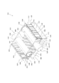
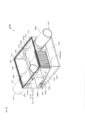
- FIG. 1 is an internal permeation perspective view showing the overall configuration of the gas-liquid separation device 1010 according to the first embodiment.
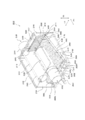
- FIG. 2 is an internal permeation perspective view showing an outline of the internal configuration of the gas-liquid separation device 1010 according to the first embodiment.
- FIG. 3 is an internal permeation perspective view showing an outline of the internal configuration of the gas-liquid separation device 1010 according to the first embodiment.
- FIG. 4 is an internal permeation perspective view showing an outline of the internal configuration of the gas-liquid separation device 1010 according to the first embodiment.
- FIG. 5 is an internal permeation perspective view showing an outline of the internal configuration of the gas-liquid separation device 1010 according to the first embodiment.
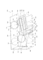
- FIG. 6 is a perspective front view showing an outline of the internal configuration of the gas-liquid separation device 1010 according to the first embodiment.
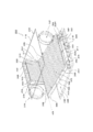
- FIG. 7 is an internal permeation perspective view showing an outline of the internal configuration of the gas-liquid separation device 1010 according to the first embodiment.
- FIG. 8 is an internal permeation perspective view showing an outline of the internal configuration of the gas-liquid separation device 1010 according to the first embodiment.
- FIG. 9 shows the right V-shaped groove forming portion 1400, the right inclined V-shaped groove forming portion 1470, the left side V-shaped groove forming portion 1600, and the left side inclined V-shaped groove forming portion 1670 of the gas-liquid separation device 1010 according to the first embodiment. It is sectional drawing which shows the outline of the front V-shaped groove forming part 2400, and the inclined V-shaped groove forming part 2470 of the gas-liquid separation apparatus 2010 by 2nd Embodiment.
- FIG. 10 is a schematic view showing a gas-liquid two-phase flow, a liquid phase, and a gas phase flow in the gas-liquid separation device 1010 according to the first embodiment.
- the gas-liquid separation device 1010 according to the first embodiment mainly includes an inlet pipe 1200, a right V-shaped groove forming portion 1400, a right inclined V-shaped groove forming portion 1470, a left inclined V-shaped groove forming portion 1670, and a left V-shaped portion. It has a groove forming portion 1600 and an outlet pipe 1300.
- the right V-shaped groove forming portion 1400 has a V-shaped groove portion 1402 in cross section
- the right inclined V-shaped groove forming portion 1470 has a V-shaped groove portion 1472 in cross section and is inclined to the left side.
- the V-shaped groove forming portion 1670 has a groove portion 1672 having a V-shaped cross section
- the left V-shaped groove forming portion 1600 has a groove portion 1602 having a V-shaped cross section.
- the gas-liquid two-phase flow sucked from the inlet pipe 1200 is, in order, the groove 1402 of the right V-shaped groove forming portion 1400, the groove 1472 of the right inclined V-shaped groove forming portion 1470, and the groove portion 1672 of the left inclined V-shaped groove forming portion 1670. , It comes into contact with the groove 1602 of the left V-shaped groove forming portion 1600, and is separated into a gas phase and a liquid phase by surface tension. The separated gas phase is discharged from the outlet pipe 1300, and the separated liquid phase is discharged from the drain port 1800.
- the gas-liquid separation device 1010 is a device that separates the gas phase and the liquid phase by the grooves of the four V-shaped groove forming portions in this way.
- the gas-liquid separation device 1010 has a housing 1100.
- the housing 1100 has a substantially square columnar shape.
- the housing 1100 has a top surface portion 1110, a bottom surface portion 1120, a front surface portion 1130, a back surface portion 1140, a right side surface portion 1150, and a left side surface portion 1160.
- the top surface portion 1110, the bottom surface portion 1120, the front surface portion 1130, the back surface portion 1140, the right side surface portion 1150, and the left side surface portion 1160 have a substantially plate-like rectangular shape.
- the housing 1100 has a substantially square columnar shape, and has a substantially square tubular side surface portion and two bottom surface portions facing each other across the side surface portion.
- the side surface portion of the housing 1100 is composed of a top surface portion 1110, a bottom surface portion 1120, a right side surface portion 1150, and a left side surface portion 1160. Further, the bottom surface portion of the housing 1100 is composed of a front surface portion 1130 and a back surface portion 1140.
- the top surface portion 1110, the bottom surface portion 1120, the front surface portion 1130, the back surface portion 1140, the right side surface portion 1150, and the left side surface portion 1160 may be configured separately or integrally. Further, the thicknesses of the top surface portion 1110, the bottom surface portion 1120, the front surface portion 1130, the back surface portion 1140, the right side surface portion 1150, and the left side surface portion 1160 are appropriately determined according to various conditions such as the temperature and pressure inside the housing 1100. be able to.
- the top surface portion 1110 is provided with an airflow control unit 1115 to prevent the gas-liquid two-phase flow from approaching the top surface portion 1110 so that the gas-liquid two-phase flow can be caused by a right-sided inclined V-shaped groove forming portion 1470 or the like.
- the flow of the gas-liquid two-phase flow can be controlled so as to approach the left-side inclined V-shaped groove forming portion 1670.
- the front surface portion 1130 has a front opening 1132 for a suction pipe and a front opening 1134 for a discharge pipe.
- the back surface portion 1140 has a back opening 1142 for a suction pipe and a back opening 1144 for a discharge pipe.
- the front opening 1132 for the suction pipe, the front opening 1134 for the discharge pipe, the back opening 1142 for the suction pipe, and the back opening 1144 for the discharge pipe are through holes having a substantially circular shape.
- the front opening 1132 for the suction pipe and the back opening 1142 for the suction pipe lock or hold the inlet pipe 1200 described later.
- the discharge pipe front opening 1134 and the discharge pipe back opening 1144 lock and hold the outlet pipe 1300 and the inlet pipe 1200, which will be described later. Details will be described in detail later.
- the gas-liquid separation device 1010 has an inlet pipe 1200.
- the inlet pipe 1200 has a constant radius and a long cylindrical shape.
- the cylindrical side surface 1210 of the inlet pipe 1200 has a substantially cylindrical shape.
- the inlet pipe 1200 is arranged perpendicular to the front surface portion 1130 and the back surface portion 1140.
- the inlet pipe 1200 can be arranged parallel to the top surface portion 1110 and the bottom surface portion 1120, and parallel to the right side surface portion 1150 and the left side surface portion 1160.
- the inlet pipe 1200 is arranged through the front opening 1132 for the suction pipe and is held by the front opening 1132 for the suction pipe.
- the inlet pipe 1200 is arranged so that the uppermost portion 1250 of the inlet pipe 1200 is substantially in contact with the inner surface of the top surface portion 1110 from the front portion 1130 to the back portion 1140.
- the uppermost portion 1250 of the inlet pipe 1200 is the uppermost portion of the cylindrical side surface 1210 of the inlet pipe 1200.
- the inlet tube 1200 has a suction opening 1220 and a locking opening 1230.
- the suction opening 1220 and the locking opening 1230 are openings formed at two ends in the longitudinal direction of the inlet pipe 1200, and are through holes having a substantially circular shape.
- the suction opening 1220 is an opening for sucking a gas-liquid two-phase flow and introducing it into the housing 1100.
- the locking opening 1230 is a circular through hole.
- the locking opening 1230 engages with the suction tube back opening 1142 and is sealed by the suction sealer 1146.
- the suction sealing body 1146 has a substantially circular shape and is attached in close contact with the locking opening 1230 to seal the locking opening 1230 of the inlet pipe 1200. Since the locking opening 1230 is sealed by the suction sealing body 1146, the gas-liquid two-phase flow sucked from the suction opening 1220 is not discharged from the locking opening 1230.
- the inlet tube 1200 has a plurality of, eg, 7 discharge openings 1240.
- the seven discharge openings 1240 have a substantially circular shape with the same radius.
- the seven discharge openings 1240 are formed at equal intervals on the cylindrical side surface 1210 of the inlet pipe 1200.
- the seven discharge openings 1240 face the right V-shaped groove forming portion 1400, which will be described later, along the longitudinal direction of the inlet pipe 1200.
- the gas-liquid two-phase flow sucked from the suction opening 1220 is discharged from each of the seven discharge openings 1240 toward the right V-shaped groove forming portion 1400, and the gas-liquid two-phase flow is discharged from the right V-shaped groove forming portion 1400, which will be described later. It comes into contact with the groove portion 1402 of the portion 1400.
- the gas-liquid separation device 1010 has an outlet pipe 1300.
- the outlet pipe 1300 has a constant radius and a long cylindrical shape.
- the cylindrical side surface 1310 of the outlet pipe 1300 has a substantially cylindrical shape.
- the outlet pipe 1300 is arranged perpendicular to the front surface portion 1130 and the back surface portion 1140.
- the outlet pipe 1300 can be arranged parallel to the top surface portion 1110 and the bottom surface portion 1120, and parallel to the right side surface portion 1150 and the left side surface portion 1160.
- the outlet pipe 1300 is arranged through the discharge pipe back opening 1144 and is held by the discharge pipe front opening 1134.
- the outlet pipe 1300 is arranged so that the uppermost portion 1350 of the outlet pipe 1300 is substantially in contact with the inner surface of the top surface portion 1110 from the back portion 1140 to the front portion 1130.
- the uppermost portion 1350 of the outlet pipe 1300 is a portion located on the uppermost side of the cylindrical side surface 1310 of the outlet pipe 1300.
- the outlet pipe 1300 has a discharge opening 1320 and a locking opening 1330.
- the discharge opening 1320 and the locking opening 1330 are openings formed at two ends in the longitudinal direction of the outlet pipe 1300, and are through holes having a substantially circular shape.
- the discharge opening 1320 is an opening for discharging the gas phase and leading it to the outside of the housing 1100. If the gas-liquid separation device 1010 cannot sufficiently separate the gas phase and the liquid phase, it is assumed that the unseparated gas-liquid two-phase flow is discharged from the discharge opening 1320. Further, even when the gas-liquid two-phase flow is separated into the gas phase and the liquid phase, it is assumed that the liquid phase is discharged from the discharge opening 1320.
- the locking opening 1330 is a circular through hole.
- the locking opening 1330 engages with the discharge pipe front opening 1134 and is sealed by the discharge sealer 1136.
- the discharge sealing body 1136 has a substantially circular shape and is attached in close contact with the locking opening 1330 to seal the locking opening 1330 of the outlet pipe 1300. Since the locking opening 1330 is sealed by the discharge sealing body 1136, the gas phase or the gas-liquid two-phase flow is not sucked into the outlet pipe 1300 from the locking opening 1330.
- the outlet pipe 1300 has a plurality of, for example, seven suction openings 1340.
- the seven suction openings 1340 have a substantially circular shape with the same radius.
- the seven suction openings 1340 are formed at equal intervals on the cylindrical side surface 1310 of the outlet pipe 1300.
- the seven suction openings 1340 face the left V-shaped groove forming portion 1600, which will be described later, along the longitudinal direction of the outlet pipe 1300.
- the gas phase is sucked into the outlet pipe 1300 through the seven suction openings 1340, and is led out from the discharge opening 1320 of the outlet pipe 1300 to the outside of the housing 1100.
- Position of inlet pipe 1200 and outlet pipe 1300 By arranging the inlet pipe 1200 and the outlet pipe 1300 as described above, the inlet pipe 1200 and the outlet pipe 1300 are both positioned substantially in contact with the inner surface of the top surface portion 1110 (the same height in the vertical direction TB). And are arranged parallel to each other. That is, the inlet pipe 1200 and the outlet pipe 1300 are arranged at the uppermost positions on the inner surface of the housing 1100.
- Drainage port 1800 is an opening for discharging the liquid phase separated from the gas-liquid two-phase flow to the outside of the housing 1100.
- the drainage port 1800 has a substantially circular shape.
- the drainage port 1800 is formed on the front surface portion 1130 directly above the bottom surface portion 1120.
- a connecting member 1850 for connecting a drain hose (not shown) can be connected to the drain port 1800.
- the drainage guide groove portion 1810 is a groove body for temporarily storing the separated liquid phase and guiding the separated liquid phase to the drainage port 1800.
- the drainage guide groove portion 1810 communicates with the drainage port 1800, stores the liquid phase transmitted through the right side inclined bottom portion 1450 and the left side inclined bottom portion 1650, which will be described later, and guides the liquid phase toward the drainage port 1800.
- the drainage guide groove portion 1810 includes a drainage inclined portion 1820, a drainage right side wall portion 1830, a drainage left side wall portion 1840, and a part of the bottom surface portion 1120.
- the drainage guide groove portion 1810 has a long shape, and is formed by connecting substantially half of the left-right direction LR of the bottom surface portion 1120 along the front-rear direction FR (see the alternate long and short dash line HBO in FIG. 7).
- the drainage inclined portion 1820 has an elongated shape and a flat inclined surface.
- the drainage inclined portion 1820 is formed so as to be inclined so that the back surface portion 1140 is the highest and the drainage inclined portion 1820 is gradually lowered toward the front surface portion 1130.
- the drainage slope 1820 can guide the liquid phase toward the drainage port 1800 formed on the front surface 1130.
- the drainage inclined portion 1820 is a long region sandwiched between the drainage right side wall portion 1830 and the drainage left side wall portion 1840 facing each other.
- ⁇ Drainage right side wall 1830 and drainage left side wall 1840> The drainage right side wall portion 1830 and the drainage left side wall portion 1840 are arranged so as to face each other in parallel with the drainage inclined portion 1820.
- the upper end 1832 of the drainage right side wall 1830 is higher than the upper end 1842 of the drainage left side wall 1840.
- the drainage right side wall portion 1830 has a flat surface and is arranged perpendicular to the bottom surface portion 1120.
- the drainage right wall portion 1830 has an upper end portion 1832 and a lower end portion 1834.
- the upper end 1832 of the drainage right wall 1830 coincides with the lower end 1454 of the right inclined bottom 1450.
- the lower end 1834 of the drainage right wall 1830 coincides with the bottom surface 1120.
- the drainage left side wall portion 1840 has a flat surface and is arranged perpendicular to the bottom surface portion 1120.
- the drainage left wall portion 1840 has an upper end portion 1842 and a lower end portion 1844.
- the upper end 1842 of the drainage left wall 1840 coincides with the lower end 1654 of the left inclined bottom 1650.
- the lower end 1844 of the drainage left wall 1840 coincides with the bottom surface 1120.
- the drainage port 1800 is formed on the front portion 1130, but the drainage port 1800 may be formed on the back portion 1140.
- the liquid phase can be discharged from the back surface portion 1140.
- Right side V-shaped groove forming portion 1400 comes into contact with the gas-liquid two-phase flow discharged from the discharge opening 1240 of the inlet pipe 1200 to separate the liquid phase and the gas phase, and the separated liquid phase is separated into the right inclined bottom portion 1450. I will guide you to.
- the right V-shaped groove forming portion 1400 is a grooved body, and has a plurality of elongated groove portions 1402 having a substantially V-shaped cross section.
- the plurality of grooves 1402 are positioned parallel to each other.
- the right V-shaped groove forming portion 1400 has a long concave portion 1404 (valley) having a substantially V-shaped cross section and a long convex portion 1406 (mountain) having a substantially inverted V-shaped cross section. Part) and are repeatedly formed in parallel with each other.
- the liquid phase component is held in the groove 1402 by the action of surface tension and flows down.
- the gas phase component is separated from the liquid phase component and separated from the groove portion 1402. In this way, the groove 1402 ensures that the gas-liquid two-phase flow is separated into a gas phase and a liquid phase.
- the right V-shaped groove forming portion 1400 has a plurality of groove portions 1402, but has a thin plate-like shape as a whole. That is, the valley bottoms of the recesses 1404 of all the grooves 1402 are located along one plane, and the peaks of the convex portions 1406 of all the grooves 1402 are also along another plane parallel to one plane. Is located.
- the front and back surfaces of the right V-shaped groove forming portion 1400 are formed in the same manner, and the concave portion 1404 (valley portion) on the front surface becomes the convex portion 1406 (mountain portion) on the back surface and the convex portion 1406 (mountain portion) on the front surface. Is a recess 1404 (valley) on the front surface of the back surface. Therefore, the liquid phase and the gas phase can be separated regardless of whether the gas-liquid two-phase flow contacts the front surface of the right V-shaped groove forming portion 1400 or the back surface.
- the right V-shaped groove forming portion 1400 is arranged in the upper half of the right surface portion 1150 facing the right surface portion 1150. That is, by extending the plurality of groove portions 1402 of the right side V-shaped groove forming portion 1400 over the upper half of the right side surface portion 1150 (half of the top surface portion 1110 side), the gas-liquid two-phase flow forms the right V-shaped groove. The region that can come into contact with the portion 1400 can be increased to increase the opportunity for separation into the liquid phase and the gas phase.
- the plurality of groove portions 1402 are arranged so that the longitudinal direction of the plurality of groove portions 1402 is along the vertical direction. That is, the plurality of groove portions 1402 are arranged in the longitudinal direction of the plurality of groove portions 1402 from the top surface portion 1110 toward the bottom surface portion 1120. By doing so, the liquid phase separated by contacting with the plurality of groove portions 1402 is guided downward along the groove portions 1402.
- the right V-shaped groove forming portion 1400 has an upper end portion 1412 and a lower end portion 1414.
- the upper end portion 1412 of the right V-shaped groove forming portion 1400 is located substantially in contact with the inner surface of the top surface portion 1110.
- the lower end portion 1414 of the right side V-shaped groove forming portion 1400 is located substantially in contact with the inner surface of the upper end portion 1456 of the right side inclined bottom portion 1450.
- the right V-groove forming portion 1400 has a front end portion 1416 and a rear end portion 1418.
- the front end 1416 of the right V-groove forming portion 1400 is in contact with the inner surface of the front end 1130, and the rear end 1418 is in contact with the inner surface of the back surface 1140.
- the groove portion 1402 has a substantially V-shaped cross section.
- the groove angle of the groove portion 1402 is preferably less than 90 degrees (acute angle). As shown in FIG. 9A, the groove angle refers to the angle ⁇ formed by two groove surfaces facing each other across the valley bottom of the recess 1404 (valley).
- the number of times the gas-liquid two-phase flow comes into contact with the groove 1402 can be appropriately adjusted depending on the groove angle ⁇ , the depth of the recess 1404 (or the height of the mountain), the position of contact with the groove 1402, and the like. ..
- the right inclined bottom portion 1450 has a flat shape except for the portion of the two ribs 1452 described later.
- the right side inclined bottom portion 1450 is arranged so as to be inclined so as to gradually lower from the right side surface portion 1150 toward the left side surface portion 1160.
- the right-side inclined bottom portion 1450 is inclined so as to form an ⁇ 1 (acute angle) with respect to the horizontal direction.
- the right inclined bottom portion 1450 guides the liquid phase flowing from the right V-shaped groove forming portion 1400 toward the drainage guide groove portion 1810.
- the right inclined bottom portion 1450 has a lower end portion 1454 and an upper end portion 1456.
- the upper end portion 1456 of the right side inclined bottom portion 1450 is positioned at the horizontal central portion HCR (see FIGS. 2 and 5) in which substantially half of the vertical direction TB of the right side surface portion 1150 is connected along the front-rear direction FR.
- the lower end 1454 of the right inclined bottom 1450 is positioned at the upper end 1832 of the drain right wall 1830 of the drain guide groove 1810.
- the right-side inclined bottom portion 1450 extends from the right-side surface portion 1150 to the upper end portion 1832 of the drainage right-side wall portion 1830 of the drainage guide groove portion 1810 while gradually decreasing.
- the right inclined bottom portion 1450 is formed in close contact with the right surface portion 1150.
- the right side inclined bottom portion 1450 may be formed integrally with the right side surface portion 1150 or may be formed separately. By forming in this way, the gas-liquid two-phase flow, the liquid phase, and the gas phase do not leak to the right lower space 1460, which will be described later.
- the right inclined bottom 1450 has a plurality of ribs, for example, two parallel ribs 1452.
- the rib 1452 has a long, thin plate-like shape and is erected on the surface of the right inclined bottom portion 1450.
- the rib 1452 is formed from the right side surface portion 1150 to the upper end portion 1832 of the drainage right side wall portion 1830 of the drainage guide groove portion 1810.
- the rib 1452 contacts the back side of the convex portion 1476 (mountain portion) of the right inclined V-shaped groove forming portion 1470, which will be described later, and supports the right inclined V-shaped groove forming portion 1470.
- Right lower space 1460 is a space surrounded by a bottom surface portion 1120, a front surface portion 1130, a back surface portion 1140, a right side inclined bottom portion 1450, a right side surface portion 1150, and a drainage right side wall portion 1830.
- a device or component such as a heat source in the lower right space 1460, it is possible to prevent the liquid phase from freezing. By doing so, the lower right space 1460 can be effectively utilized.
- Right side inclined V-shaped groove forming portion 1470 contacts the gas-liquid two-phase flow that was not separated by the right-side V-shaped groove forming portion 1400, separates the liquid phase and the gas phase, and separates the separated liquid phase into the drainage guide groove portion. I will guide you to 1810.
- the right-side inclined V-shaped groove forming portion 1470 has a plurality of elongated groove portions 1472 having a substantially V-shaped cross section.
- the plurality of grooves 1472 are positioned parallel to each other.
- the right-side inclined V-shaped groove forming portion 1470 has a long concave portion 1474 (valley portion) having a substantially V-shaped cross section and a long convex portion 1476 (long convex portion) having a substantially inverted V-shaped cross section. Yamabe) is repeatedly formed in parallel with each other.
- the liquid phase component is held by the groove 1472 by the action of surface tension and flows down.
- the gas phase component is separated from the liquid phase component and separated from the groove portion 1472. In this way, the groove portion 1472 ensures that the gas-liquid two-phase flow is separated into a gas phase and a liquid phase.
- the right-side inclined V-shaped groove forming portion 1470 has a plurality of groove portions 1472, but has a thin plate-like shape as a whole. That is, the valley bottoms of the recesses 1474 of all the grooves 1472 are located along one plane, and the peaks of the protrusions 1476 of all the grooves 1472 are also along another plane parallel to one plane. Is located.
- the front and back surfaces of the right-side inclined V-shaped groove forming portion 1470 are formed in the same manner as the right-side V-shaped groove forming portion 1400, and the concave portion 1474 (valley portion) on the front surface is the convex portion 1476 (mountain portion) on the back surface.
- the convex portion 1476 (mountain portion) on the front surface becomes the concave portion 1474 (valley portion) on the front surface of the back surface. Therefore, the liquid phase and the gas phase can be separated regardless of whether the gas-liquid two-phase flow comes into contact with the front surface of the right V-shaped groove forming portion 1470 or the back surface.
- the right inclined V-shaped groove forming portion 1470 is arranged above the right inclined bottom portion 1450, substantially parallel to the right inclined bottom portion 1450, separated from the right inclined bottom portion 1450, and covers the right inclined bottom portion 1450. With this configuration, the right side inclined gap portion 1500 can be formed between the right side inclined V-shaped groove forming portion 1470 and the right side inclined bottom portion 1450. As described above, the right inclined V-groove forming portion 1470 is supported at a fixed position by the two ribs 1452 of the right inclined bottom portion 1450. The right-side inclined V-shaped groove forming portion 1470 inclines at an acute angle of ⁇ 1 with respect to the horizontal direction.
- the right-side inclined V-shaped groove forming portion 1470 is integrally formed with the two ribs 1452, or is fixed to the two ribs 1452 by a fixing tool such as a screw or a locking tool, or the two ribs. It can be fixed by being welded to 1452.
- the right-side inclined V-shaped groove forming portion 1470 may be supported at a fixed position and in a fixed posture.
- the plurality of groove portions 1472 are arranged so that the longitudinal direction of the plurality of groove portions 1472 is parallel to the right inclined bottom portion 1450 and along the left-right direction LR. That is, the plurality of groove portions 1472 are arranged so as to gradually lower toward the left side surface portion 1160.
- the liquid phase separated by the gas-liquid two-phase flow coming into contact with the plurality of groove portions 1472 flows down the groove portion 1472.
- the gas-liquid two-phase flow that was not separated by the right-side inclined V-shaped groove forming portion 1470 is guided to the left-side inclined V-shaped groove forming portion 1670, which will be described later.
- the right side inclined V-shaped groove forming portion 1470 has an upper end portion 1482 and a lower end portion 1484.
- the upper end portion 1482 of the right side inclined V-shaped groove forming portion 1470 is located at a distance from the right side V-shaped groove forming portion 1400. That is, a right gap portion 1550 was formed between the lower end portion 1414 of the right V-shaped groove forming portion 1400 and the upper end portion 1482 of the right side inclined V-shaped groove forming portion 1470. Further, as described above, the right side inclined bottom portion 1450 is formed in close contact with the right side surface portion 1150.
- the liquid phase separated by the right V-shaped groove forming portion 1400 is not guided by the right inclined V-shaped groove forming portion 1470, and is arranged below the right inclined V-shaped groove forming portion 1470. Immediately flow down to the drainage guide groove portion 1810. Further, since the liquid phase from the right V-shaped groove forming portion 1400 is not guided to the right-side inclined V-shaped groove forming portion 1470, the gas-liquid two-phase flow that was not separated by the right-side V-shaped groove forming portion 1400 is inclined to the right. By actively guiding the V-shaped groove forming portion 1470 and bringing it into contact with the groove portion 1472, the liquid phase can be separated at the right-side inclined V-shaped groove forming portion 1470.
- the gas-liquid two-phase flow that was not separated by the right V-shaped groove forming portion 1400 is also guided between the right inclined V-shaped groove forming portion 1470 and the right inclined bottom portion 1450.
- the gas-liquid two-phase flow also contacts the back side of the convex portion 1476 (mountain portion) of the right-side inclined V-shaped groove forming portion 1470, and is separated into the liquid phase and the gas phase in the same manner as the groove portion 1472, and the drainage guide groove portion. It flows down to 1810.
- the lower end portion 1484 of the right side inclined V-shaped groove forming portion 1470 is located above the lower end portion 168 of the left side inclined V-shaped groove forming portion 1670, which will be described later, and covers a part of the left side inclined V-shaped groove forming portion 1670.
- the gas-liquid two-phase flow that was not separated by the right-side inclined V-shaped groove forming portion 1470 can be guided to the left-side inclined V-shaped groove forming portion 1670.
- the liquid phase separated by the right-side inclined V-shaped groove forming portion 1470 is once guided to the lower end portion 1684 of the left-side inclined V-shaped groove forming portion 1670, and then flows down to the drainage guide groove portion 1810.
- the right-sided inclined V-groove forming portion 1470 has a front end portion 1486 and a rear end portion 1488.
- the front end 1486 of the right inclined V-groove forming portion 1470 is in contact with the inner surface of the front surface portion 1130
- the rear end portion 1488 is in contact with the inner surface of the back surface portion 1140.
- the cross-sectional shape of the groove portion 1472 is the same as the cross-sectional shape of the groove portion 1402 (see FIG. 9), and the groove angle of the groove portion 1472 is less than 90 degrees (acute angle). By doing so, the possibility that the gas-liquid two-phase flow comes into contact with the groove portion 1472 more (for example, three times or more) can be increased, and the gas-liquid two-phase flow can be easily separated into the liquid phase and the gas phase. ..
- the number of times the gas-liquid two-phase flow comes into contact with the groove portion 1472 can be appropriately adjusted depending on the groove angle ⁇ , the depth of the recess 1474 (or the height of the mountain), the position of contact with the groove portion 1472, and the like. ..
- the right side gap portion 1550 is formed between the lower end portion 1414 of the right side V-shaped groove forming portion 1400 and the upper end portion 1482 of the right side inclined V-shaped groove forming portion 1470, and the right side inclined V-shaped groove forming portion 1470.
- a right-side inclined gap portion 1500 is formed between the right-side inclined bottom portion 1450 and the right-side inclined bottom portion 1450. Therefore, the gas-liquid two-phase flow that was not separated by the right V-shaped groove forming portion 1400 may enter the right inclined gap portion 1500 via the right gap portion 1550.
- the front and back surfaces of the right-side inclined V-shaped groove forming portion 1470 are formed in the same manner, and the gas-liquid two-phase flow comes into contact with the right-side inclined V-shaped groove forming portion 1470 even on the right-side inclined gap portion 1500 side. Then, the liquid phase and the gas phase can be separated at the right inclined gap portion 1500. Therefore, by separating the gas-liquid two-phase flow into the liquid phase and the gas phase on both the front surface and the back surface of the right-side inclined V-shaped groove forming portion 1470, the liquid phase and the gas phase can be efficiently separated. Can be done.
- the left inclined bottom 1650 has an approximately flat shape.
- the left inclined bottom portion 1650 is arranged so as to be inclined so as to gradually decrease from the left surface portion 1160 toward the right surface portion 1150.
- the left inclined bottom portion 1650 is inclined so as to form an ⁇ 2 (acute angle) with respect to the horizontal direction.
- the left inclined bottom portion 1650 guides the liquid phase flowing from the left V-shaped groove forming portion 1600, which will be described later, toward the drainage guide groove portion 1810.
- the left inclined bottom portion 1650 has a lower end portion 1654 and an upper end portion 1656.
- the upper end portion 1656 of the left inclined bottom portion 1650 is positioned at the horizontal central portion HCL (see FIG. 4) in which substantially half of the vertical TB of the left surface portion 1160 is connected along the front-rear direction FR.
- the lower end 1654 of the left inclined bottom 1650 is located at the upper end 1842 of the drain left wall 1840 of the drain guide groove 1810.
- the left inclined bottom portion 1650 extends from the left surface portion 1160 to the upper end portion 1842 of the drainage left wall portion 1840 of the drainage guide groove portion 1810 while gradually decreasing.
- the left inclined bottom portion 1650 is formed in close contact with the left surface portion 1160.
- the left inclined bottom portion 1650 may be formed integrally with the left surface portion 1160 or may be formed separately.
- the left inclined bottom portion 1650 contacts the back side of the recess 1674 (valley portion) of the left inclined V-shaped groove forming portion 1670, which will be described later, and supports the left inclined V-shaped groove forming portion 1670.
- Left side inclined V-shaped groove forming portion 1670 >>> The left inclined V-shaped groove forming portion 1670 comes into contact with the gas-liquid two-phase flow that was not separated by the right inclined V-shaped groove forming portion 1470, separates the liquid phase and the gas phase, and guides the separated liquid phase to drainage. Guide to the groove 1810.
- the left inclined V-shaped groove forming portion 1670 has a plurality of elongated groove portions 1672 having a substantially V-shaped cross section.
- the plurality of grooves 1672 are positioned parallel to each other.
- the left inclined V-shaped groove forming portion 1670 has a long concave portion 1674 (valley portion) having a substantially V-shaped cross section and a long convex portion 1676 having a substantially inverted V-shaped cross section. Yamabe) is repeatedly formed in parallel with each other.
- the liquid phase component is held by the groove portion 1672 by the action of surface tension and flows down.
- the gas phase component is separated from the liquid phase component and separated from the groove portion 1672. In this way, the groove portion 1672 ensures that the gas-liquid two-phase flow is separated into a gas phase and a liquid phase.
- the left inclined V-shaped groove forming portion 1670 has a plurality of groove portions 1672, but has a thin plate-like shape as a whole. That is, the valley bottoms of the recesses 1674 of all the grooves 1672 are located along one plane, and the peaks of the protrusions 1676 of all the grooves 1472 are also along another plane parallel to one plane. Is located.
- the left side inclined V-shaped groove forming portion 1670 also has the same front and back surfaces as the right side V-shaped groove forming portion 1400, and the concave portion 1674 (valley portion) on the front surface is the convex portion 1676 (mountain portion) on the back surface. ), And the convex portion 1676 (mountain portion) on the front surface becomes the concave portion 1674 (valley portion) on the front surface of the back surface. Therefore, the liquid phase and the gas phase can be separated regardless of whether the gas-liquid two-phase flow comes into contact with the front surface of the left inclined V-shaped groove forming portion 1670 or the back surface.
- the left inclined V-shaped groove forming portion 1670 is arranged above the left inclined bottom portion 1650, substantially parallel to the left inclined bottom portion 1650, separated from the left inclined bottom portion 1650, and covers the left inclined bottom portion 1650. With this configuration, the left side inclined gap portion 1700 can be formed between the left side inclined V-shaped groove forming portion 1670 and the left side inclined bottom portion 1650.
- the left inclined V-groove forming portion 1670 is supported at a fixed position by the left inclined bottom portion 1650.
- the left inclined V-shaped groove forming portion 1670 is integrally formed with the left inclined bottom portion 1650, fixed to the left inclined bottom portion 1650 by a fixing tool such as a screw or a locking tool, or welded to the left inclined bottom portion 1650. It can be fixed by being welded.
- the left inclined V-shaped groove forming portion 1670 may be supported at a fixed position and in a fixed posture.
- the left-side inclined V-shaped groove forming portion 1670 is inclined so as to form an ⁇ 2 (acute angle) with respect to the horizontal direction.
- ⁇ 2 ⁇ 1
- the angles ⁇ 1 and ⁇ 2 can be appropriately changed according to the flow rate of the gas-liquid two-phase flow introduced into the housing 1100 and the like.
- ⁇ 2 ⁇ 1 may be set.
- the left inclined V-shaped groove forming portion 1670 is arranged above the right inclined V-shaped groove forming portion 1470. More specifically, it is preferable that the lower end portion 1684 of the left inclined V-shaped groove forming portion 1670 is arranged above the lower end portion 1484 of the right inclined V-shaped groove forming portion 1470, and ⁇ 2 ⁇ 1.
- the gas-liquid two-phase flow that has entered the right-side inclined gap portion 1500 can be guided to the back side of the left-side inclined V-shaped groove forming portion 1670, and the gas-liquid two-phase flow is sucked into the suction opening 1340. Therefore, it is possible to prevent the gas from being discharged from the discharge opening 1320, and to separate the gas-liquid two-phase flow into the liquid phase and the gas phase on the back side of the left inclined V-shaped groove forming portion 1670.
- the plurality of groove portions 1672 are arranged so that the longitudinal direction of the plurality of groove portions 1672 is parallel to the left inclined bottom portion 1650 and along the left-right direction LR. That is, the plurality of groove portions 1672 are arranged so as to gradually lower toward the right side surface portion 1150.
- the liquid phase separated by the gas-liquid two-phase flow coming into contact with the plurality of groove portions 1672 flows down the groove portion 1672.
- the gas-liquid two-phase flow that was not separated by the right-side inclined V-shaped groove forming portion 1470 is guided by the left-side inclined V-shaped groove forming portion 1670 and comes into contact with the plurality of groove portions 1672.
- the left inclined V-shaped groove forming portion 1670 has an upper end portion 1682 and a lower end portion 1684.
- the upper end portion 1682 of the left inclined V-shaped groove forming portion 1670 is located at a distance from the left V-shaped groove forming portion 1600. That is, a left gap portion 1750 was formed between the lower end portion 1614 of the left V-shaped groove forming portion 1600 and the upper end portion 1682 of the left inclined V-shaped groove forming portion 1670. Further, as described above, the left side inclined bottom portion 1650 is formed in close contact with the left side surface portion 1160.
- the liquid phase separated by the left side V-shaped groove forming portion 1600 is not guided by the left side inclined V-shaped groove forming portion 1670, and is arranged below the left side inclined V-shaped groove forming portion 1670. Immediately flow down to the drainage guide groove portion 1810. Further, since the liquid phase from the left V-shaped groove forming portion 1600 is not guided to the left inclined V-shaped groove forming portion 1670, the gas-liquid two-phase flow that was not separated by the right V-shaped groove forming portion 1400 is inclined to the left side. By actively guiding the V-shaped groove forming portion 1670 and bringing it into contact with the groove portion 1672, the liquid phase can be separated at the left inclined V-shaped groove forming portion 1670. By arranging in this way, the liquid phase separated by the left V-shaped groove forming portion 1600 is immediately guided to the drainage guide groove portion 1810 by the left inclined bottom portion 1650.
- the lower end portion 1648 of the left inclined V-shaped groove forming portion 1670 is located below the lower end portion 1484 of the right inclined V-shaped groove forming portion 1470 described above, and is covered with a part of the right inclined V-shaped groove forming portion 1470.
- the left inclined V-groove forming portion 1670 has a front end portion 1686 and a rear end portion 1688.
- the front end 1686 of the left inclined V-groove forming portion 1670 is in contact with the inner surface of the front surface portion 1130, and the rear end portion 1688 is in contact with the inner surface of the back surface portion 1140.
- the cross-sectional shape of the groove portion 1672 is the same as the cross-sectional shape of the groove portion 1402 (see FIG. 9), and the groove angle of the groove portion 1672 is less than 90 degrees (acute angle). By doing so, the possibility that the gas-liquid two-phase flow comes into contact with the groove portion 1672 more (for example, three times or more) can be increased, and the gas-liquid two-phase flow can be easily separated into the liquid phase and the gas phase. ..
- the number of times the gas-liquid two-phase flow comes into contact with the groove portion 1672 can be appropriately adjusted depending on the groove angle ⁇ , the depth of the recess 1674 (or the height of the mountain), the position of contact with the groove portion 1672, and the like. ..
- the right inclined gap portion 1500 is formed between the right inclined V-shaped groove forming portion 1470 and the right inclined bottom portion 1450, and the left inclined V-shaped groove forming portion 1670 and the left inclined bottom portion 1650 are formed.
- the left inclined gap portion 1700 is formed.
- the gas-liquid two-phase flow that has not been separated in the right-side inclined gap portion 1500 may enter the left-side inclined gap portion 1700.
- the front and back surfaces of the left inclined V-shaped groove forming portion 1670 are formed in the same manner, and the gas-liquid two-phase flow comes into contact with the left inclined V-shaped groove forming portion 1670 even on the left inclined gap portion 1700 side.
- the liquid phase and the gas phase can be separated at the left inclined gap portion 1700. Therefore, by separating the gas-liquid two-phase flow into the liquid phase and the gas phase on both the front surface and the back surface of the left inclined V-shaped groove forming portion 1670, the liquid phase and the gas phase can be efficiently separated. Can be done.
- Left V-shaped groove forming portion 1600 is guided by the gas-liquid two-phase flow that was not separated by the left inclined bottom portion 1650, and comes into contact with the groove portion 1602 of the left V-shaped groove forming portion 1600, and further becomes a liquid phase and a gas phase. And guide the separated liquid phase.
- the left V-shaped groove forming portion 1600 has a plurality of elongated groove portions 1602 having a substantially V-shaped cross section.
- the plurality of grooves 1602 are positioned parallel to each other.
- the left V-shaped groove forming portion 1600 has a long concave portion 1604 (valley) having a substantially V-shaped cross section and a long convex portion 1606 (mountain) having a substantially inverted V-shaped cross section. Part) and are repeatedly formed in parallel with each other.
- the liquid phase component is held by the groove portion 1602 by the action of surface tension and flows down.
- the gas phase component is separated from the liquid phase component and separated from the groove portion 1602. In this way, the groove 1602 ensures that the gas-liquid two-phase flow is separated into a gas phase and a liquid phase.
- the left V-shaped groove forming portion 1600 has a plurality of groove portions 1602, but has a thin plate-like shape as a whole. That is, the valley bottoms of the recesses 1604 of all the grooves 1602 are located along one plane, and the peaks of the protrusions 1606 of all the grooves 1602 are also along another plane parallel to one plane. Is located.
- the left side V-shaped groove forming portion 1600 also has the same front and back surfaces as the right side V-shaped groove forming portion 1400, and the concave portion 1604 (valley portion) on the front surface is the convex portion 1606 (mountain portion) on the back surface.
- the convex portion 1606 (peak portion) on the front surface becomes the concave portion 1604 (valley portion) on the front surface of the back surface. Therefore, the liquid phase and the gas phase can be separated regardless of whether the gas-liquid two-phase flow comes into contact with the front surface of the left V-shaped groove forming portion 1600 or the back surface.
- the left V-shaped groove forming portion 1600 is arranged so as to face the left surface portion 1160 and occupy the upper half portion of the left surface portion 1160. That is, by arranging over the upper half of the left side surface portion 1160 (half of the top surface portion 1110 side), the area where the gas-liquid two-phase flow comes into contact with the left side V-shaped groove forming portion 1600 can be increased, and the liquid phase can be increased. And the gas phase can be separated.
- the longitudinal direction of the plurality of groove portions 1602 is arranged along the vertical direction. That is, the plurality of groove portions 1602 are arranged from the top surface portion 1110 toward the bottom surface portion 1120. By doing so, the liquid phase separated in contact with the plurality of groove portions 1602 is guided downward along the groove portions 1602.
- the left V-shaped groove forming portion 1600 has an upper end portion 1612 and a lower end portion 1614.
- the upper end portion 1612 of the left V-shaped groove forming portion 1600 is located substantially in contact with the inner surface of the top surface portion 1110. Further, the lower end portion 1614 of the left V-shaped groove forming portion 1600 is located at the upper end portion 1656 of the right inclined bottom portion 1450.
- the left V-groove forming portion 1600 has a front end portion 1616 and a rear end portion 1618.
- the front end 1616 of the left V-groove forming portion 1600 is in contact with the inner surface of the front end 1130, and the rear end 1618 is in contact with the inner surface of the back surface 1140.
- the cross-sectional shape of the groove portion 1602 is the same as the cross-sectional shape of the groove portion 1402 (see FIG. 9), and the groove angle of the groove portion 1602 is less than 90 degrees (acute angle). By doing so, the possibility that the gas-liquid two-phase flow comes into contact with the groove portion 1602 more (for example, three times or more) can be increased, and the liquid phase and the gas phase can be easily separated.
- the number of times the gas-liquid two-phase flow comes into contact with the groove portion 1602 can be appropriately adjusted depending on the groove angle ⁇ , the depth of the recess 1604 (or the height of the mountain), the position of contact with the groove portion 1602, and the like. ..
- the left lower space 1660 is a space surrounded by a bottom surface portion 1120, a front surface portion 1130, a back surface portion 1140, a left side inclined bottom portion 1650, a left side surface portion 1160, and a drainage left side wall portion 1840.
- a device or component such as a heat source in the lower left space 1660, it is possible to prevent the liquid phase from freezing. By doing so, the left lower space 1660 can be effectively utilized.
- a right side gap portion 1550 is formed between the lower end portion 1414 of the right side V-shaped groove forming portion 1400 and the upper end portion 1482 of the right side inclined V-shaped groove forming portion 1470, and the right side V-shaped groove forming portion 1450 is formed.
- the liquid phase flowing through the forming portion 1400 is immediately guided to the right inclined bottom portion 1450 without being guided by the right inclined V-shaped groove forming portion 1470.
- Gas-liquid separation by the left inclined V-shaped groove forming portion 1670 >> The gas-liquid two-phase flow not separated by the right inclined V-shaped groove forming portion 1470 (white arrow TP3 in FIG. 10) is guided to the left inclined V-shaped groove forming portion 1670 (white arrow TP4 in FIG. 10). ..
- the gas-liquid two-phase flow comes into contact with the groove portion 1672 of the left inclined V-shaped groove forming portion 1670, and is separated into a gas phase and a liquid phase by surface tension.
- the liquid phase flows through the left inclined V-shaped groove forming portion 1670 (black arrow LP7 in FIG. 10), flows down from the lower end portion 1684, and is guided toward the drainage guide groove portion 1810 (black arrow LP6 in FIG. 10). ).
- the lower end portion 1484 of the right inclined V-shaped groove forming portion 1470 is located above the lower end portion 168 of the left inclined V-shaped groove forming portion 1670 described later, and is a part of the left inclined V-shaped groove forming portion 1670. (See FIGS. 6 and 10).
- the flow of the gas-liquid two-phase flow that was not separated by the right-side inclined V-shaped groove forming portion 1470 can be positively guided directly above the left-side inclined V-shaped groove forming portion 1670.
- the gas-liquid two-phase flow can be easily brought into contact with the left-side inclined V-shaped groove forming portion 1670.
- Gas-liquid separation by the left V-shaped groove forming portion 1600 >> The gas-liquid two-phase flow not separated by the left inclined V-shaped groove forming portion 1670 is guided to the left V-shaped groove forming portion 1600 (white arrow TP5 in FIG. 10).
- the gas-liquid two-phase flow comes into contact with the groove portion 1602 of the left V-shaped groove forming portion 1600 and is separated into a gas phase and a liquid phase by surface tension.
- the liquid phase flows through the left V-shaped groove forming portion 1600 (black arrow LP8 in FIG. 10), flows through the left inclined bottom portion 1650 (black arrow LP9 in FIG. 10), flows down from the lower end portion 1684, and drains from the drainage guide groove portion.
- a left gap portion 1750 is formed between the lower end portion 1614 of the left V-shaped groove forming portion 1600 and the upper end portion 1682 of the left inclined V-shaped groove forming portion 1670, and flows through the left V-shaped groove forming portion 1600.
- the liquid phase is immediately guided to the left inclined bottom portion 1650 without being guided to the left inclined V-shaped groove forming portion 1670.
- the liquid phase separated by the right V-shaped groove forming portion 1400 flows through the right V-shaped groove forming portion 1400 (black arrow LP1 in FIG. 10) and is guided by the right inclined bottom portion 1450 (FIG. 10).
- the black arrow LP2) is guided toward the drainage guide groove portion 1810.
- the liquid phase separated by the right inclined V-shaped groove forming portion 1470 (black arrow LP4 in FIG. 10) flows through the right inclined V-shaped groove forming portion 1470 and passes through the left inclined V-shaped groove forming portion 1670 (FIG. 10).
- the black arrow LP5) is guided toward the drainage guide groove portion 1810 (black arrow LP6 in FIG. 10).
- the liquid phase separated by the left inclined V-shaped groove forming portion 1670 flows through the left inclined V-shaped groove forming portion 1670 (black arrow LP7 in FIG. 10) and is guided toward the drainage guide groove portion 1810.
- the liquid phase separated by the left V-shaped groove forming portion 1600 flows through the left inclined bottom portion 1650 (black arrow LP9 in FIG. 10) and is guided toward the drainage guide groove portion 1810. (Black arrow LP6 in FIG. 10). All of the liquid phases separated in this way are guided by the drainage guide groove portion 1810 and discharged from the drainage port 1800.
- the drainage guide groove portion 1810 is formed in the central region of the left-right direction LR of the bottom surface portion 1120.
- the right-side inclined bottom portion 1450 and the right-side inclined V-shaped groove forming portion 1470 are arranged so that the right side surface portion 1150 is the highest and gradually decreases toward the central region of the left-right direction LR.
- the left side inclined bottom portion 1650 and the left side inclined V-shaped groove forming portion 1670 are arranged so that the left side surface portion 1160 is the highest and gradually decreases toward the central region of the left-right direction LR. Therefore, the separated liquid phase easily flows toward the central region of the LR in the left-right direction, and flows down toward the drainage guide groove portion 1810.
- the gas-liquid separation device 1010 when the gas-liquid separation device 1010 is mounted on a vehicle such as a vehicle, the gas-liquid separation device 1010 may tilt, vibrate, or receive an impact in the left-right direction LR when passing through a curve. .. Even in such a case, one of the liquid phase from the right inclined bottom portion 1450 and the right inclined V-shaped groove forming portion 1470 and the liquid phase from the left inclined bottom portion 1650 and the left inclined V-shaped groove forming portion 1670. Can be guided to the drainage guide groove portion 1810 and discharged from the gas-liquid separation device 1010.
- the airflow control unit 1115 is provided on the top surface portion 1110 so that the gas-liquid two-phase flow, the gas phase, and the liquid phase do not approach the top surface portion 1110. Therefore, it can be positively guided to the right side inclined V-shaped groove forming portion 1470 and the left side inclined V-shaped groove forming portion 1670.
- the airflow control unit 1115 can increase the chances of separating the gas-liquid two-phase flow into a gas phase and a liquid phase at the right-side inclined V-shaped groove forming portion 1470 and the left-side inclined V-shaped groove forming portion 1670.
- FIG. 11 is an internal permeation perspective view showing the overall configuration of the gas-liquid separation device 2010 according to the second embodiment.
- FIG. 12 is an internal permeation perspective view showing the overall configuration of the gas-liquid separation device 2010 according to the second embodiment.
- FIG. 13 is an internal permeation perspective view showing the overall configuration of the gas-liquid separation device 2010 according to the second embodiment.
- FIG. 14 is an internal permeation plan view showing the overall configuration of the gas-liquid separation device 2010 according to the second embodiment.
- FIG. 15 is an internal permeation right side view showing the overall configuration of the gas-liquid separation device 2010 according to the second embodiment.
- FIG. 16 is an internal permeation left side view showing the overall configuration of the gas-liquid separation device 2010 according to the second embodiment.
- the gas-liquid separation device 2010 according to the second embodiment mainly has an inlet pipe 2200, a front V-shaped groove forming portion 2400, an inclined V-shaped groove forming portion 2470, and an outlet pipe 2300.
- the front V-shaped groove forming portion 2400 has a groove portion 2402 having a V-shaped cross section
- the inclined V-shaped groove forming portion 2470 has a groove portion 2472 having a V-shaped cross section.
- the gas-liquid two-phase flow sucked from the inlet pipe 2200 contacts the groove portion 2402 of the front V-shaped groove forming portion 2400 and the groove portion 2472 of the inclined V-shaped groove forming portion 2470 in order, and the gas phase and the liquid phase are brought into contact with each other by surface tension. Separate into and. The separated gas phase is discharged from the outlet pipe 2300, and the separated liquid phase is discharged from the drain port 2800.
- the gas-liquid separation device 2010 is a device that separates the gas phase and the liquid phase by the grooves of the two V-shaped groove forming portions in this way.
- the gas-liquid separation device 2010 has a housing 2100.
- the housing 2100 has a substantially square columnar shape.
- the housing 2100 has a top surface portion 2110, a bottom surface portion 2120, a front surface portion 2130, a back surface portion 2140, a right side surface portion 2150, and a left side surface portion 2160.
- the top surface portion 2110, the bottom surface portion 2120, the front surface portion 2130, the back surface portion 2140, the right side surface portion 2150, and the left side surface portion 2160 have a substantially plate-like rectangular shape.
- the housing 2100 has a substantially square columnar shape, and has a substantially square tubular side surface portion and two bottom surface portions facing each other across the side surface portion.
- the side surface portion of the housing 2100 is composed of a top surface portion 2110, a bottom surface portion 2120, a right side surface portion 2150, and a left side surface portion 2160. Further, the bottom surface portion of the housing 2100 is composed of a front surface portion 2130 and a back surface portion 2140.
- the top surface portion 2110, the bottom surface portion 2120, the front surface portion 2130, the back surface portion 2140, the right side surface portion 2150, and the left side surface portion 2160 may be configured separately or integrally. Further, the thicknesses of the top surface portion 2110, the bottom surface portion 2120, the front surface portion 2130, the back surface portion 2140, the right side surface portion 2150, and the left side surface portion 2160 are appropriately determined according to various conditions such as the temperature and pressure inside the housing 2100. be able to.
- the front surface portion 2130 has a front opening 2132 for a suction pipe.
- the back surface portion 2140 has a back surface opening 2144 for a discharge pipe.
- the front opening 2132 for the suction pipe and the back opening 2144 for the discharge pipe are through holes having a circular shape.
- the front opening 2132 for the suction pipe locks and holds the inlet pipe 2200 described later.
- the discharge pipe back opening 2144 locks and holds the outlet pipe 2300 described later. Details will be described in detail later.
- the gas-liquid separation device 2010 has an inlet pipe 2200.
- the inlet pipe 2200 has a constant radius and a long cylindrical shape.
- the cylindrical side surface 2210 of the inlet pipe 2200 has a substantially cylindrical shape.
- the inlet pipe 2200 is arranged perpendicular to the front surface portion 2130 and the back surface portion 2140.
- the inlet pipe 2200 can be arranged parallel to the top surface portion 2110 and the bottom surface portion 2120, and parallel to the right side surface portion 2150 and the left side surface portion 2160.
- the inlet pipe 2200 is arranged so as to penetrate the front opening 2132 for the suction pipe and is held by the front opening 2132 for the suction pipe.
- the inlet pipe 2200 is arranged so that the uppermost portion 2250 of the inlet pipe 2200 is substantially in contact with the inner surface of the top surface portion 2110 from the front portion 2130 to the back portion 2140.
- the uppermost portion 2250 of the inlet pipe 2200 is a portion located on the uppermost side of the cylindrical side surface 2210 of the inlet pipe 2200.
- the inlet tube 2200 has a suction opening 2220 and a discharge opening 2240.
- the suction opening 2220 and the discharge opening 2240 are openings formed at two ends in the longitudinal direction of the inlet pipe 2200, and are through holes having a substantially circular shape.
- the suction opening 2220 is an opening for sucking a gas-liquid two-phase flow and introducing it into the housing 2100.
- the discharge opening 2240 is a circular through hole.
- the discharge opening 2240 faces the front V-shaped groove forming portion 2400, which will be described later.
- the gas-liquid two-phase flow sucked from the suction opening 2220 is discharged from the discharge opening 2240 toward the front V-shaped groove forming portion 2400, and the gas-liquid two-phase flow is discharged from the groove portion 2402 of the front V-shaped groove forming portion 2400 described later. Contact with.
- the gas-liquid separation device 2010 has an outlet pipe 2300.
- the outlet pipe 2300 has a constant radius and a long cylindrical shape.
- the cylindrical side surface 2310 of the outlet pipe 2300 has a substantially cylindrical shape.
- the outlet pipe 2300 is arranged perpendicular to the front surface portion 2130 and the back surface portion 2140.
- the outlet pipe 2300 can be arranged parallel to the top surface portion 2110 and the bottom surface portion 2120, and parallel to the right side surface portion 2150 and the left side surface portion 2160.
- the outlet pipe 2300 is arranged so as to penetrate the back opening 2144 for the discharge pipe and is held by the back opening 2144 for the discharge pipe.
- the outlet pipe 2300 is arranged so that the uppermost portion 2350 of the outlet pipe 2300 is substantially in contact with the inner surface of the top surface portion 2110 from the back surface portion 2140 to the front surface portion 2130.
- the uppermost portion 2350 of the outlet pipe 2300 is a portion located on the uppermost side of the inner surface of the cylindrical side surface 2310 of the outlet pipe 2300.
- the outlet pipe 2300 has a discharge opening 2320 and a suction opening 2340.
- the discharge opening 2320 and the suction opening 2340 are openings formed at two ends in the longitudinal direction of the outlet pipe 2300, and are through holes having a substantially circular shape.
- the discharge opening 2320 is an opening for discharging the gas phase and leading it to the outside of the housing 2100. If the gas-liquid separation device 2010 cannot sufficiently separate the gas phase and the liquid phase, it is assumed that the unseparated gas-liquid two-phase flow is discharged from the discharge opening 2320.
- the suction opening 2340 is a circular through hole. The gas phase is sucked into the outlet pipe 2300 from the suction opening 2340 and led out from the discharge opening 2320 of the outlet pipe 2300 to the outside of the housing 2100.
- Position of inlet pipe 2200 and outlet pipe 2300 By arranging the inlet pipe 2200 and the outlet pipe 2300 as described above, the inlet pipe 2200 and the outlet pipe 2300 are both located at positions in contact with the inner surface of the top surface portion 2110 (the same height in the vertical direction TB). And they are arranged parallel to each other. That is, the inlet pipe 2200 and the outlet pipe 2300 are arranged at the uppermost positions on the inner surface of the housing 2100.
- Drainage port 2800 is an opening for discharging the liquid phase separated from the gas-liquid two-phase flow to the outside of the housing 2100.
- the drainage port 2800 has a substantially circular shape.
- the drainage port 2800 is formed on the front surface portion 2130 directly above the bottom surface portion 2120.
- a connecting member 2850 for connecting a drain hose (not shown) can be connected to the drain port 2800.
- the drainage guide groove portion 2810 is a groove body for temporarily storing the separated liquid phase and guiding the separated liquid phase to the drainage port 2800.
- the drainage guide groove portion 2810 communicates with the drainage port 2800, stores the liquid phase transmitted through the inclined bottom portion 2450 described later, and guides the liquid phase toward the drainage port 2800.
- the drainage guide groove portion 2810 includes a right drainage inclined portion 2820R, a left drainage inclined portion 2820L, a drainage front portion 2836, and a part of the bottom surface portion 2120.
- the drainage guide groove portion 2810 has a long shape along the LR in the left-right direction, and is formed on the bottom surface portion 2120 substantially in contact with the inner surface of the front surface portion 2130.
- the right drainage inclined portion 2820R and the left drainage inclined portion 2820L have a long shape and a flat inclined surface.
- the right drainage inclined portion 2820R is formed so as to have the highest right side surface portion 2150 and gradually decrease toward the drainage port 2800.
- the left drainage inclined portion 2820L is formed so as to be inclined so that the left side surface portion 2160 is the highest and gradually decreases toward the drainage port 2800.
- the right drainage inclined portion 2820R and the left drainage inclined portion 2820L can guide the liquid phase toward the drainage port 2800 formed in the front surface portion 2130.
- the drainage port 2800 is formed on the front portion 2130, but the drainage port 2800 may be formed on the back portion 2140.
- the liquid phase can be discharged from the back surface portion 2140.
- the back inclined portion 2430 has a substantially flat shape.
- the back surface inclined portion 2430 has an acute angle ⁇ 3 (see FIG. 15) with respect to the back surface portion 2140, and is formed so as to gradually approach the back surface portion 2110 toward the back surface portion 2140.
- a front V-shaped groove forming portion 2400 which will be described later, is arranged on the back inclined portion 2430.
- Front V-shaped groove forming portion 2400 comes into contact with the gas-liquid two-phase flow discharged from the discharge opening 2240 of the inlet pipe 2200 to separate the liquid phase and the gas phase, and the separated liquid phase is transferred to the inclined bottom 2450. invite.
- the front V-shaped groove forming portion 2400 is a grooved body, and has a plurality of elongated groove portions 2402 having a substantially V-shaped cross section.
- the plurality of grooves 2402 are positioned parallel to each other.
- the front V-shaped groove forming portion 2400 has a long concave portion 2404 (valley) having a substantially V-shaped cross section and a long convex portion 2406 (mountain) having a substantially inverted V-shaped cross section. Part) and are repeatedly formed in parallel with each other.
- the liquid phase component is held by the groove 2402 by the action of surface tension and flows down.
- the gas phase component is separated from the liquid phase component and separated from the groove portion 2402. In this way, the groove 2402 ensures that the gas-liquid two-phase flow is separated into a gas phase and a liquid phase.
- the front V-shaped groove forming portion 2400 has a plurality of groove portions 2402, but has a thin plate-like shape as a whole. That is, the valley bottoms of the recesses 2404 of all the grooves 2402 are located along one plane, and the peaks of the convex portions 2406 of all the grooves 2402 are also along another plane parallel to one plane. Is located.
- the front and back surfaces of the front V-shaped groove forming portion 2400 are formed in the same manner, and the concave portion 2404 (valley portion) on the front surface becomes the convex portion 2406 (mountain portion) on the back surface and the convex portion 2406 (mountain portion) on the front surface. Is a recess 2404 (valley) on the front surface of the back surface. Therefore, the liquid phase and the gas phase can be separated regardless of whether the gas-liquid two-phase flow comes into contact with the front surface of the front V-shaped groove forming portion 2400 or the back surface.
- the front V-shaped groove forming portion 2400 is arranged on the back inclined portion 2430.
- the back inclined portion 2430 is formed on the upper half (half on the top surface portion 2110 side) of the back surface portion 2140. Therefore, the plurality of groove portions 2402 of the front V-shaped groove forming portion 2400 can be extended over the upper half (half of the top surface portion 2110 side) of the back surface portion 2140, and the gas-liquid two-phase flow is front V-shaped.
- the region that can come into contact with the groove forming portion 2400 can be increased to increase the chance that the liquid phase and the gas phase can be separated.
- the front V-shaped groove forming portion 2400 is arranged on the back inclined portion 2430. That is, in the plurality of groove portions 2402, the longitudinal direction of the plurality of groove portions 2402 is arranged along the back surface inclined portion 2430. By doing so, the liquid phase separated in contact with the plurality of groove portions 2402 is guided downward along the groove portions 2402.
- the front V-shaped groove forming portion 2400 has an upper end portion 2412 and a lower end portion 2414.
- the upper end portion 2412 of the front V-shaped groove forming portion 2400 is located substantially in contact with the inner surface of the top surface portion 2110.
- the lower end portion 2414 of the front V-shaped groove forming portion 2400 is located substantially in contact with the inner surface of the upper end portion 2456 of the inclined bottom portion 2450.
- the front V-shaped groove forming portion 2400 has a right end portion 2416 and a left end portion 2418.
- the right end 2416 of the front V-shaped groove forming portion 2400 is in contact with the inner surface of the right side surface portion 2150, and the left end portion 2418 is located near the right side of the cylindrical side surface 2310 of the outlet pipe 2300.
- the gas-liquid two-phase flow can come into contact with the front V-shaped groove forming portion 2400.
- the region can be enlarged to increase the chance of separation between the liquid phase and the gas phase.
- the groove portion 2402 has a substantially V-shaped cross section.
- the groove angle of the groove portion 2402 is preferably less than 90 degrees (acute angle). As shown in FIG. 9A, the groove angle refers to the angle ⁇ formed by two groove surfaces facing each other across the valley bottom of the recess 2404 (valley).
- the number of times the gas-liquid two-phase flow comes into contact with the groove portion 2402 can be appropriately adjusted depending on the groove angle ⁇ , the depth of the recess 2404 (or the height of the mountain), the position of contact with the groove portion 2402, and the like. ..
- the front V-shaped groove forming portion 2400 alone cannot sufficiently separate the liquid phase and the gas phase.
- the front V-shaped groove forming portion 2400 is arranged on the back surface inclined portion 2430, and the back surface inclined portion 2430 is arranged at an acute angle ⁇ 3 with respect to the back surface portion 2140. Therefore, the gas-liquid two-phase flow that is not separated by the front V-shaped groove forming portion 2400 is reflected by the front V-shaped groove forming portion 2400 and guided toward the inclined V-shaped groove forming portion 2470 described later.
- the liquid phase and the gas phase can be separated.
- the inclined bottom 2450 has a substantially flat shape.
- the inclined bottom portion 2450 has an acute angle ⁇ 4 (see FIGS. 15 and 16) with respect to the horizontal direction, and the inclined bottom portion 2450 is arranged so as to gradually decrease from the back surface portion 2140 toward the front surface portion 2130.
- the inclined bottom portion 2450 guides the liquid phase flowing from the front V-shaped groove forming portion 2400 toward the drainage guide groove portion 2810.
- the inclined bottom portion 2450 has a lower end portion 2454 and an upper end portion 2456.
- the upper end portion 2456 of the inclined bottom portion 2450 is positioned at the horizontal central portion HCB (see FIG. 11) in which substantially half of the vertical TB of the back surface portion 2140 is connected along the horizontal LR.
- the lower end 2454 of the inclined bottom 2450 coincides with the upper end 2832 of the drainage guide groove 2810. In this way, the inclined bottom portion 2450 extends from the back surface portion 2140 to the upper end portion 2832 of the drainage guide groove portion 2810 while gradually decreasing.
- the inclined bottom portion 2450 is formed in close contact with the right side surface portion 2150.
- the inclined bottom portion 2450 may be formed integrally with the right side surface portion 2150 or may be formed separately.
- the inclined bottom 2450 has a plurality of, for example, three parallel ribs 2452.
- the rib 2452 has a long and thin plate-like shape, and is erected on the surface of the inclined bottom portion 2450.
- the rib 2452 is formed from the right side surface portion 2150 to the upper end portion 2832 of the drainage guide groove portion 2810.
- the rib 2452 contacts the back side of the convex portion 2476 (mountain portion) of the inclined V-shaped groove forming portion 2470 to be described later, and supports the inclined V-shaped groove forming portion 2470.
- Lower space 2460 is a space surrounded by a bottom surface portion 2120, a drainage front surface portion 2836, a back surface portion 2140, an inclined bottom portion 2450, a right side surface portion 2150, and a left side surface portion 2160.
- a device or component such as a heat source in the lower space 2460, it is possible to prevent the liquid phase from freezing. By doing so, the lower space 2460 can be effectively utilized.
- Inclined V-shaped groove forming portion 2470 contacts the gas-liquid two-phase flow that was not separated by the front V-shaped groove forming portion 2400, separates the liquid phase and the gas phase, and separates the separated liquid phase into the drainage guide groove portion 2810. I will guide you to.
- the inclined V-shaped groove forming portion 2470 has a plurality of elongated groove portions 2472 having a substantially V-shaped cross section.
- the plurality of grooves 2472 are positioned parallel to each other.
- the inclined V-shaped groove forming portion 2470 has a long recess 2474 (valley) having a substantially V-shaped cross section and a long convex portion 2476 (mountain) having a substantially inverted V-shaped cross section. Part) and are repeatedly formed in parallel with each other.
- the liquid phase component is held by the groove portion 2472 by the action of surface tension and flows down.
- the gas phase component is separated from the liquid phase component and separated from the groove portion 2472. In this way, the groove portion 2472 ensures that the gas-liquid two-phase flow is separated into a gas phase and a liquid phase.
- the inclined V-shaped groove forming portion 2470 has a plurality of groove portions 2472, but has a thin plate-like shape as a whole. That is, the valley bottoms of the recesses 2474 of all the grooves 2472 are located along one plane, and the peaks of the protrusions 2476 of all the grooves 2472 are also along another plane parallel to one plane. Is located.
- the inclined V-shaped groove forming portion 2470 also has the same front and back surfaces, and the concave portion 2474 (valley portion) on the front surface becomes the convex portion 2476 (mountain portion) on the back surface.
- the convex portion 2476 (mountain portion) on the front surface becomes the concave portion 2474 (valley portion) on the front surface on the back surface. Therefore, the liquid phase and the gas phase can be separated regardless of whether the gas-liquid two-phase flow comes into contact with the front surface of the inclined V-shaped groove forming portion 2470 or the back surface.
- the inclined V-shaped groove forming portion 2470 is arranged above the inclined bottom portion 2450, substantially parallel to the inclined bottom portion 2450, separated from the inclined bottom portion 2450, and covers the inclined bottom portion 2450. With this configuration, an inclined gap portion 2500 can be formed between the inclined V-shaped groove forming portion 2470 and the inclined bottom portion 2450. As described above, the inclined V-groove forming portion 2470 is supported at a fixed position by the three ribs 2452 of the inclined bottom portion 2450.
- the inclined V-shaped groove forming portion 2470 is integrally formed with the three ribs 2452, or is fixed to the three ribs 2452 by a fixing tool such as a screw or a locking tool, or the three ribs 2452. It can be fixed by being welded to.
- the inclined V-shaped groove forming portion 2470 may be supported at a fixed position and in a fixed posture.
- the plurality of groove portions 2472 are arranged so that the longitudinal direction of the plurality of groove portions 2472 is parallel to the inclined bottom portion 2450 and along the left-right direction LR. That is, the plurality of groove portions 2472 are arranged so as to gradually lower toward the drainage front portion 2836. The liquid phase separated by the gas-liquid two-phase flow coming into contact with the plurality of groove portions 2472 flows down the groove portion 2472.
- the inclined V-shaped groove forming portion 2470 has an upper end portion 2482 and a lower end portion 2484.
- the upper end portion 2482 of the inclined V-shaped groove forming portion 2470 is located at a distance from the front V-shaped groove forming portion 2400. That is, a gap portion 2550 was formed between the lower end portion 2414 of the front V-shaped groove forming portion 2400 and the upper end portion 2482 of the inclined V-shaped groove forming portion 2470. Further, as described above, the inclined bottom portion 2450 is formed in close contact with the right side surface portion 2150.
- the liquid phase separated by the front V-shaped groove forming portion 2400 is not guided by the inclined V-shaped groove forming portion 2470, but is guided by the inclined bottom portion 2450 arranged below the inclined V-shaped groove forming portion 2470. Then, it immediately flows down into the drainage guide groove 2810. Further, since the liquid phase from the front V-shaped groove forming portion 2400 is not guided to the inclined V-shaped groove forming portion 2470, the gas-liquid two-phase flow that was not separated by the front V-shaped groove forming portion 2400 is separated by the inclined V-shaped groove forming portion 2400. By actively guiding the groove forming portion 2470 and bringing it into contact with the groove portion 2472, the inclined V-shaped groove forming portion 2470 can separate the liquid phase.
- the gas-liquid two-phase flow that was not separated by the front V-shaped groove forming portion 2400 is also guided between the inclined V-shaped groove forming portion 2470 and the inclined bottom portion 2450.
- the gas-liquid two-phase flow also contacts the back side of the convex portion 2476 (mountain portion) of the inclined V-shaped groove forming portion 2470, and is separated into the liquid phase and the gas phase in the same manner as the groove portion 2472, and the drainage guide groove portion 2810. Flow down to.
- liquid phase separated by the inclined V-shaped groove forming portion 2470 is once guided by the lower end portion 2484 and flows down to the drainage guide groove portion 2810.
- the inclined V-shaped groove forming portion 2470 has a right end portion 2486 and a left end portion 2488.
- the right end portion 2486 of the inclined V-shaped groove forming portion 2470 is in contact with the inner surface of the right side surface portion 2150
- the left end portion 2488 is in contact with the inner surface of the left side surface portion 2160.
- the cross-sectional shape of the groove portion 2472 is the same as the cross-sectional shape of the groove portion 2402 (see FIG. 9), and the groove angle of the groove portion 2472 is less than 90 degrees (acute angle). By doing so, the possibility that the gas-liquid two-phase flow comes into contact with the groove portion 2472 more (for example, three times or more) can be increased, and the gas-liquid two-phase flow can be easily separated into the liquid phase and the gas phase. ..
- the number of times the gas-liquid two-phase flow comes into contact with the groove portion 2472 can be appropriately adjusted depending on the groove angle ⁇ , the depth of the recess 2474 (or the height of the mountain), the position of contact with the groove portion 2472, and the like. ..
- a gap portion 2550 is formed between the lower end portion 2414 of the front V-shaped groove forming portion 2400 and the upper end portion 2482 of the inclined V-shaped groove forming portion 2470, and the inclined V-shaped groove forming portion 2470 and the inclined bottom portion are formed.
- An inclined gap portion 2500 is formed between the vehicle and the 2450. Therefore, the gas-liquid two-phase flow that has not been separated by the front V-shaped groove forming portion 2400 may enter the inclined gap portion 2500 via the gap portion 2550.
- the front and back surfaces of the inclined V-shaped groove forming portion 2470 are formed to be the same, and even on the inclined gap portion 2500 side, the gas-liquid two-phase flow comes into contact with the inclined V-shaped groove forming portion 2470, so that the inclined V-shaped groove forming portion 2470 is inclined.
- the liquid phase and the gas phase can be separated at the gap portion 2500. Therefore, by separating the gas-liquid two-phase flow into the liquid phase and the gas phase on both the front surface and the back surface of the inclined V-shaped groove forming portion 2470, it is possible to efficiently separate the gas-liquid phase into the gas phase. it can.
- Gas-liquid separation by the front V-shaped groove forming portion 2400 >>> ⁇ Gas-liquid separation by the front V-shaped groove forming portion 2400 >> The gas-liquid two-phase flow (white arrow TP20 in FIGS. 14, 15, and 16) sucked from the inlet pipe 2200 is discharged from the discharge opening 2240 of the inlet pipe 2200 toward the front V-shaped groove forming portion 2400. (White arrow TP21 in FIGS. 14 and 15). The gas-liquid two-phase flow discharged from the discharge opening 2240 comes into contact with the groove portion 2402 of the front V-shaped groove forming portion 2400, and is separated into a gas phase and a liquid phase by surface tension. The liquid phase flows through the front V-groove forming portion 2400 (black arrow LP21 in FIGS.
- a gap portion 2550 is formed between the lower end portion 2414 of the front V-shaped groove forming portion 2400 and the upper end portion 2482 of the inclined V-shaped groove forming portion 2470, and the front V-shaped groove forming portion is formed.
- the liquid phase flowing through the 2400 is immediately guided to the inclined bottom portion 2450 without being guided to the inclined V-shaped groove forming portion 2470.
- Gas-liquid separation by the inclined V-shaped groove forming portion 2470 >> The gas-liquid two-phase flow not separated by the front V-shaped groove forming portion 2400 is guided to the inclined V-shaped groove forming portion 2470 (white arrows TP22 in FIGS. 14, 15, and 16).
- the gas-liquid two-phase flow comes into contact with the groove portion 2472 of the inclined V-shaped groove forming portion 2470, and is separated into a gas phase and a liquid phase by surface tension.
- the liquid phase flows through the inclined V-shaped groove forming portion 2470 (black arrow LP24 in FIGS. 14, 15, and 16) and flows down from the lower end portion 2484 of the inclined V-shaped groove forming portion 2470 (FIGS. 15 and 16).
- the black arrow LP25 guides the user toward the drainage guide groove 2810 (black arrow LP23 in FIGS. 15 and 16).
- the liquid phase separated by the front V-shaped groove forming portion 2400 flows through the front V-shaped groove forming portion 2400 (black arrows LP21 in FIGS. 15 and 16) and is guided by the inclined bottom portion 2450 ( The black arrow LP22) in FIGS. 14, 15, and 16 is guided toward the drainage guide groove portion 2810.
- the liquid phase separated by the inclined V-shaped groove forming portion 2470 flows through the inclined V-shaped groove forming portion 2470 and is guided toward the drainage guide groove portion 2810. (Black arrows LP25 in FIGS. 15 and 16).
- the drainage guide groove portion 2810 is formed along the left-right direction LR of the bottom surface portion 2120.
- the inclined bottom portion 2450 and the inclined V-shaped groove forming portion 2470 are arranged so that the back surface portion 2140 is the highest and the inclined bottom portion 2130 is gradually lowered toward the front surface portion 2130. Therefore, the separated liquid phase easily flows toward the front surface portion 2130 and flows down toward the drainage guide groove portion 2810.
- the gas-liquid separation device 2010 When the gas-liquid separation device 2010 is mounted on a vehicle such as a vehicle, the gas-liquid separation device 2010 may tilt, vibrate, or receive an impact in the front-rear direction with the movement of the vehicle when passing through a slope. is there. Even in such a case, the liquid phase from the inclined bottom portion 2450 and the inclined V-shaped groove forming portion 2470 can be guided to the drainage guide groove portion 2810 and discharged from the gas-liquid separation device 2010.
- ⁇ Modification 1 >>>
- the right V-shaped groove forming portion 1400 and the right inclined V-shaped groove forming portion 1470 are separately configured, but the right V-shaped groove forming portion 1400 and the right side are shown.
- the inclined V-shaped groove forming portion 1470 may be integrally formed. By doing so, the configuration can be simplified.
- the right gap portion 1550 can be secured by forming an opening (boundary portion) between the right V-shaped groove forming portion 1400 and the right inclined V-shaped groove forming portion 1470.
- the left V-shaped groove forming portion 1600 and the left inclined V-shaped groove forming portion 1670 are separately configured, but the left V-shaped groove forming portion is shown.
- the 1600 and the left side inclined V-shaped groove forming portion 1670 may be integrally formed. By doing so, the configuration can be simplified.
- the left side gap portion 1750 can be secured by forming an opening (boundary portion) between the left side V-shaped groove forming portion 1600 and the left side inclined V-shaped groove forming portion 1670.
- the front V-shaped groove forming portion 2400 and the inclined V-shaped groove forming portion 2470 are separately configured, but the front V-shaped groove forming portion 2400 and The inclined V-shaped groove forming portion 2470 may be integrally formed.
- the gap portion 2550 can be secured by forming an opening (boundary portion) between the front V-shaped groove forming portion 2400 and the inclined V-shaped groove forming portion 2470.
- the left V-shaped groove forming portion 1600 and the left inclined V-shaped groove forming portion 1670 are configured separately from the housing 1100, but the left side V The character groove forming portion 1600 and the left side inclined V-shaped groove forming portion 1670 may be integrally formed with the housing 1100. By doing so, the configuration can be simplified.
- the front V-shaped groove forming portion 2400 and the inclined V-shaped groove forming portion 2470 are configured separately from the housing 1100, but the front V-shaped groove is formed.
- the forming portion 2400 and the inclined V-shaped groove forming portion 2470 may be integrally formed with the housing 1100. By doing so, the configuration can be simplified.
- Shape of housing 1100 and shape of housing 2100 The shape (outer shape or inner shape) of the housing 1100 of the gas-liquid separation device 1010 according to the first embodiment described above and the shape (outer shape or inner shape) of the housing 2100 of the gas-liquid separation device 2010 according to the second embodiment.
- the term (shape) refers to the case where all of them have a substantially square columnar shape, but other shapes may be used.
- a shape such as a columnar or elliptical columnar shape
- a polygonal columnar shape such as a triangular columnar shape can be used.
- Each of these columnar bodies has a side surface portion constituting the side surface of the columnar body and two bottom surface portions facing each other with the side surface portion interposed therebetween.
- the bottom surface constitutes a columnar bottom surface.
- the two bottom surfaces may be arranged in parallel or non-parallel.
- the shapes of the housing 1100 and the housing 2100 can be appropriately determined according to the vehicle on which the gas-liquid separation device 1010 and the gas-liquid separation device 2010 are mounted.
- the right inclined bottom portion 1450, the left inclined bottom portion 1650, the back inclined portion 2430, and the inclined bottom portion 2450 can be appropriately determined according to the shapes of the housing 1100 and the housing 2100. That is, the right inclined bottom portion 1450, the left inclined bottom portion 1650, the back inclined portion 2430, and the inclined bottom portion 2450 may have a curved shape or a bent shape instead of a flat shape. In addition to these shapes, it is possible to make a shape along the housing 1100 or a shape along the housing 2100.
- the 2470 may also be appropriately determined according to the shape of the housing 1100 and the housing 2100.
- the cross-sectional shape is not limited to the case where the cross section perpendicular to the axial direction (the shape of the housing 1100, the direction along the central axis of the housing 2100, or the direction along the extending axis) is substantially constant. Or the area may change along the axial direction. As described above, the shape of the housing 1100 and the housing 2100 are substantially square pillars, and the shape and size of the cross section perpendicular to the axial direction may be changed along the axial direction.
- ⁇ Modification 4 >>>
- the number of discharge openings 1240 is not limited to 7, and may be greater than or less than 7. It may be appropriately determined according to the distribution of the flow rate of the gas-liquid two-phase flow discharged from the discharge opening 1240.
- the radius of the discharge opening 1240 does not have to be the same.
- the radius can be gradually reduced from the front portion 1130 to the back portion 1140.
- the flow rate of the gas-liquid two-phase flow discharged from the discharge opening 1240 can be adjusted.
- the flow rates of gas-liquid two-phase flows discharged from each of the plurality of discharge openings 1240 can be made equal.
- the flow rates of the gas-liquid two-phase flow discharged from each of the plurality of discharge openings 1240 may be made different from each other so that the gas-liquid two-phase flow is discharged toward the right V-shaped groove forming portion 1400.
- the plurality of discharge openings 1240 do not have to be formed at equal intervals on the cylindrical side surface 1210 of the inlet pipe 1200.
- the spacing between the plurality of discharge openings 1240 can be appropriately determined so that the gas-liquid two-phase flow is uniformly dispersed toward the right V-shaped groove forming portion 1400.
- the intervals between the plurality of discharge openings 1240 may be determined so that the flow rate of the gas-liquid two-phase flow toward the right V-shaped groove forming portion 1400 becomes desired.
- ⁇ Modification 5 >>>
- the number of suction openings 1340 is not limited to 7, and may be greater than or less than 7. It may be appropriately determined according to the flow rate of the gas-liquid two-phase flow sucked into the outlet pipe 1300. For example, the number of suction openings 1340 may be determined so that the gas-liquid two-phase flow can be efficiently sucked into the outlet pipe 1300.
- the radii of the seven suction openings 1340 do not have to be the same.
- the radius can be gradually reduced from the back surface portion 1140 to the front surface portion 1130.
- the flow rate of the gas phase sucked from the suction opening 1340 can be adjusted.
- the flow rates of the gas phases sucked from each of the plurality of suction openings 1340 can be made equal.
- the flow rates of the gas phases sucked from each of the plurality of suction openings 1340 may be different from each other.
- the plurality of suction openings 1340 need not be formed at equal intervals on the cylindrical side surface 1310 of the outlet pipe 1300.
- the spacing between the plurality of suction openings 1340 can be appropriately determined so that the flow rates of the gas phases sucked from each of the suction openings 1340 are equal.
- the intervals between the plurality of suction openings 1340 may be determined so that the gas phase can be efficiently sucked from each of the suction openings 1340.
- the depth of the groove of the right V-shaped groove forming portion 1400 and the front V-shaped groove forming portion 2400 that first comes into contact with the gas-liquid two-phase flow is set to the remaining right-side inclined V-shaped groove forming portion 1470 and the left V-shaped groove forming portion. It can be made deeper than the groove depth of the portion 1600, the left inclined V-shaped groove forming portion 1670, and the inclined V-shaped groove forming portion 2470. Further, instead of the depth, the groove angle ⁇ , the groove spacing, and the like may be changed. It can be appropriately determined according to the flow rate and flow velocity of the gas-liquid two-phase flow.
- ⁇ Modification 7 >>>
- the right side V-shaped groove forming portion 1400 and the right side surface portion 1150 of the gas-liquid separator 1010 are shown separately for the sake of clarity. That is, it is shown that a space is generated between the right side V-shaped groove forming portion 1400 and the right side surface portion 1150.
- the inner surface of the right side surface portion 1150 may be integrated with the right side V-shaped groove forming portion 1400.
- the space formed between the right V-shaped groove forming portion 1400 and the right side surface portion 1150 may be filled with a sealing material such as an adhesive. It is possible to prevent the gas-liquid two-phase flow from entering the space.
- the front V-shaped groove forming portion 2400 and the back inclined portion 2430 of the gas-liquid separation device 2010 are shown separately. That is, it is shown that a space is generated between the front V-shaped groove forming portion 2400 and the back inclined portion 2430.
- the back inclined portion 2430 may be integrated with the front V-shaped groove forming portion 2400. By doing so, it is possible to prevent a space from being created between the front V-shaped groove forming portion 2400 and the back inclined portion 2430, and the gas-liquid two-phase flow enters the space toward the top surface portion 1110. It is possible to prevent the gas-liquid two-phase flow from being blown up.
- a sealing material such as an adhesive may be filled in the space formed between the right V-shaped groove forming portion 2400 and the back surface inclined portion 2430. It is possible to prevent the gas-liquid two-phase flow from entering the space.
- the discharge opening 2240 of the inlet pipe 2200 of the gas-liquid separator 2010 is formed in the direction perpendicular to the longitudinal direction of the inlet pipe 2200, but the discharge opening 2240 is the inlet pipe 2200. It may be formed in an oblique direction with respect to the longitudinal direction. By doing so, the direction and flow velocity of the gas-liquid two-phase flow can be adjusted. Further, the suction opening 2340 of the outlet pipe 2300 of the gas-liquid separation device 2010 was formed in the direction perpendicular to the longitudinal direction of the outlet pipe 2300, but the suction opening 2340 was formed in the longitudinal direction of the outlet pipe 2300. On the other hand, it may be formed in an oblique direction. By doing so, it is possible to adjust the direction and flow velocity of the gas phase sucked into the outlet pipe 2300.
- the inclined V-shaped groove forming portion 2470 is formed so that the distance between the inclined V-shaped groove forming portion 2470 and the inclined bottom portion 2450 (distance between the inclined gap portions 2500) is constant by the three ribs 2452.
- the case of arranging is shown.
- the distance between the inclined V-shaped groove forming portion 2470 and the inclined bottom portion 2450 may be widened as it approaches the drainage guide groove body 2810. By doing so, it is possible to reduce the flow velocity of the gas-liquid two-phase flow that has entered the inclined gap portion 2500, adjust the overall flow velocity distribution, and move the gas-liquid two-phase flow in a desired direction. ..
- the distance between the inclined V-shaped groove forming portion 2470 and the inclined bottom portion 2450 may be increased. Even when the amount of the liquid phase separated by the front V-shaped groove forming portion 2400 increases, the liquid phase can be guided to the drainage guide groove body 2810 without overflowing from the inclined gap portion 2500.
- the lower end portion 2484 of the inclined V-shaped groove forming portion 2470 and the lower end portion 2454 of the inclined bottom portion 2450 are set to be approximately the same position, but the length of the inclined V-shaped groove forming portion 2470 is shortened. May be good. By doing so, it is possible to reduce the flow velocity of the gas-liquid two-phase flow that has entered the inclined gap portion 2500, adjust the overall flow velocity distribution, and move the gas-liquid two-phase flow in a desired direction. ..
- ⁇ Modification 11 >>>
- the case where the right side drainage inclined portion 2820R and the left drainage inclined portion 2820L are provided is shown, but it is not necessary to provide either one of the drainage inclined portions.
- the liquid level of the liquid phase accumulated in the drainage guide groove body 2810 can be lowered, and the liquid phase accumulated in the drainage guide groove body 2810 can be prevented from being blown up. it can.
- ⁇ Modification 12 >>>
- the suction opening 2340 is arranged at a position relatively close to the front surface portion 2130.
- the suction opening 2340 is arranged at a position close to the front surface portion 2130 by about 18 mm to 30 mm.
- the position of the suction opening 2340 is not limited to such a position, and the suction opening 2340 can be arranged at a position away from the front surface portion 2130.
- the suction opening 2340 can be set to the position farthest from the front surface portion 2130, and the suction opening 2340 can be set to be flush with the discharge opening 2240.
- the flow velocity near the suction opening 2340 can be slowed down, the gas-liquid two-phase flow is sufficiently separated into the gas phase and the liquid phase, and the gas phase is separated into the outlet pipe. It can be discharged from 2300.
- a member that covers a part of the drainage guide groove body 1810 and the drainage guide groove body 2810 described above may be provided.
- the drainage guide groove body 1810 and the drainage guide groove body 2810 can be covered with a punching metal or the like having a plurality of through holes formed therein. By doing so, it is possible to prevent the liquid phase accumulated in the drainage guide groove body 1810 and the drainage guide groove body 2810 from being sucked into the outlet pipe 1300 and the outlet pipe 2300.
- the gas-liquid separation device 1010 according to the first embodiment and the gas-liquid separation device 2010 according to the second embodiment described above include a refrigerating device such as an air conditioner, a steam cycle device, a fuel cell vehicle, and gas-liquid. It can also be applied to mechanical devices that handle two-phase flow.
- a refrigerating device such as an air conditioner
- the gas-liquid separation device 1010 and the gas-liquid separation device 2010 are used as two phases of gas and liquid, that is, a gas phase (gas phase refrigerant) and a liquid phase (liquid phase refrigerant). It can function as a gas-liquid separator that separates the flow into a gas phase (gas phase refrigerant) and a liquid phase (liquid phase refrigerant).
- the third embodiment A is another embodiment based on the second embodiment. Therefore, for the same configuration as that of the second embodiment, the same reference numerals are used and the above description is incorporated.
- FIG. 17 is an internal permeation perspective view showing the overall configuration of the gas-liquid separator 2010A according to the third embodiment A.
- FIG. 18 is an internal permeation perspective view showing the overall configuration of the gas-liquid separator 2010A according to the third embodiment A.
- FIG. 19 is a perspective side view showing an outline of the internal configuration of the gas-liquid separator 2010A according to the third embodiment A.
- the gas-liquid separator 2010A according to the third embodiment A mainly has an inlet pipe 2200, a front V-shaped groove forming portion 2400, and an outlet pipe 2300.
- the front V-shaped groove forming portion 2400 has a groove portion 2402 having a V-shaped cross section.
- the gas-liquid two-phase flow sucked from the inlet pipe 2200 comes into contact with the groove portion 2402 of the front V-shaped groove forming portion 2400, and is separated into a gas phase and a liquid phase by surface tension.
- the separated gas phase is discharged from the outlet pipe 2300, and the separated liquid phase is discharged from the drain port 2800.
- the gas-liquid separator 2010A is a device that separates the gas phase and the liquid phase mainly by a plurality of grooves in one V-shaped groove forming portion.
- ⁇ Housing 2100 >> The description of the housing 2100 of the gas-liquid separator 2010A according to the third embodiment A incorporates the description summarized under the heading ⁇ Housing 2100 >>> in the description of the second embodiment. ..
- ⁇ Entrance pipe 2200 >>> The description of the inlet pipe 2200 of the gas-liquid separator 2010A according to the third embodiment A is described in the description of the second embodiment ⁇ inlet pipe 2200 >>> and ⁇ intake opening 2220 and discharge opening 2240>. Incorporate the description summarized under the heading.
- ⁇ Position of inlet pipe 2200 and outlet pipe 2300 The description of the positions of the inlet pipe 2200 and the outlet pipe 2300 of the gas-liquid separator 2010A according to the third embodiment A is described in ⁇ Positions of the inlet pipe 2200 and the outlet pipe 2300 >> in the description of the second embodiment. Incorporate the description summarized under the heading. However, when a part of the waterproof partition wall portion 2700A described later is interposed between the uppermost portion 2250 of the inlet pipe 2200 and the inner surface of the top surface portion 2110, only a part of the thickness of the waterproof partition wall portion 2700A is formed. , A gap may be created between the uppermost portion 2250 of the inlet pipe 2200 and the inner surface of the top surface portion 2110.
- a gap may be created between the uppermost portion 2350 of the outlet pipe 2300 and the inner surface of the top surface portion 2110. In the case of a configuration in which such a gap is generated, it is assumed that a gas-liquid two-phase flow or a gas phase or a liquid phase passes through and stays in the gap.
- Drainage port 2800 >>> The description of the drain port 2800 of the gas-liquid separator 2010A according to the third embodiment A incorporates the description summarized under the heading ⁇ Drain port 2800 >>> in the description of the second embodiment. ..
- Drainage guide groove 2810 >> The description of the drainage guide groove portion 2810 of the gas-liquid separator 2010A according to the third embodiment A is described in the description of the second embodiment ⁇ drainage guide groove portion 2810 >> and ⁇ right drainage inclined portion 2820R and left drainage. The description summarized under the heading of inclined portion 2820L> is used.
- ⁇ Back slope 2430 >>>
- the description of the back surface inclined portion 2430 of the gas-liquid separator 2010A according to the third embodiment A is summarized by the description under the heading ⁇ back surface inclined portion 2430 >> in the description of the second embodiment. Invite. However, in the present embodiment, the back surface inclined portion 2430 is formed perpendicular to the top surface portion 2110, and when it is desired to quickly guide the liquid phase separated by the front V-shaped groove forming portion 2400 to the inclined bottom portion 2450, etc. It becomes suitable.
- ⁇ Front V-shaped groove forming portion 2400 The description of the front V-shaped groove forming portion 2400 of the gas-liquid separator 2010A according to the third embodiment A is described in ⁇ front V-shaped groove forming portion 2400 >>, ⁇ groove portion 2402 in the description of the second embodiment. >, ⁇ Upper end 2412 and lower end 2414>, ⁇ Right end 2416 and left end 2418>, and ⁇ Cross-sectional shape of groove 2402>.
- the back surface inclined portion 2430 is formed perpendicular to the top surface portion 2110, and is different in that it does not have a configuration corresponding to the inclined V-shaped groove forming portion 2470 in the second embodiment. ing.
- the gas-liquid separator 2010A according to the third embodiment A has a waterproof partition wall portion 2700A.
- the details of the waterproof partition wall portion 2700A will be described below with reference to FIG.
- the waterproof partition wall portion 2700A includes a top surface waterproof partition wall portion 2710A protruding from the inner surface of the top surface portion 2110 toward the inside of the housing 2100, and a right side waterproof partition wall portion 2710A protruding from the inner surface of the right side surface portion 2150 toward the inside of the housing 2100. It has a portion 2720A and a left surface waterproof partition wall portion 2730A that projects from the inner surface of the left surface portion 2160 toward the inside of the housing 2100.
- Top waterproof partition wall 2710A In the top surface waterproof partition wall portion 2710A, in this embodiment, one flat plate-shaped projecting portion is arranged along the top surface portion 2110 from the right end of the top surface portion 2110 to the left end of the top surface portion 2110, and a discharge opening in the inlet pipe 2200. This is achieved by removing the portion overlapping the opening of the 2240 and removing the portion overlapping the cylindrical side surface 2310 of the outlet pipe 2300.
- the top surface waterproof partition wall portion 2710A is a right side top surface waterproof partition wall portion 2711A, which is a protruding portion arranged from the right end of the top surface portion 2110 to the opening end of the discharge opening 2240 in the inlet pipe 2200, and the inlet pipe 2200.
- Central top waterproof partition wall portion 2712A which is a protruding portion arranged from the opening end of the discharge opening 2240 to the cylindrical side surface 2310 of the outlet pipe 2300, and from the cylindrical side surface 2310 of the outlet pipe 2300 to the left end of the top surface portion 2110. It can be said that it has a left-side top waterproof partition wall portion 2713A, which is a protruding portion arranged over the same.
- the right top surface waterproof partition wall portion 2711A, the central top surface waterproof partition wall portion 2712A, and the left top surface waterproof partition wall portion 2713A may be arranged as one flat plate-shaped projecting portion as in this embodiment, or are separate members. It may be arranged on the top surface portion 2110. Further, the shape is not limited to a flat plate shape, and is realized by arranging a polygonal prism such as a columnar prism, a semicircular prism, or a triangular prism on the top surface portion 2110 (the side surface is in contact with the top surface portion 2110). You may.
- the right side top waterproof partition wall portion 2711A is arranged in close contact with the inner surface of the top surface portion 2110, the inner surface of the right side surface portion 2150, and the opening end of the discharge opening 2240 in the inlet pipe 2200.
- the central top surface waterproof partition wall portion 2712A is arranged in close contact with the inner surface of the top surface portion 2110, the opening end of the discharge opening 2240 in the inlet pipe 2200, and the cylindrical side surface 2310 of the outlet pipe 2300.
- the left side top waterproof partition wall portion 2713A is arranged in close contact with the inner surface of the top surface portion 2110, the cylindrical side surface 2310 of the outlet pipe 2300, and the inner surface of the left side surface portion 2160.
- the gas-liquid separator 2010A has the top surface waterproof partition wall portion 2710A, it is possible to prevent the separated liquid phase from approaching the suction opening 2340 in the outlet pipe 2300. More specifically, for example, it adhered to the inner surface of the top surface portion 2110 located near the front V-shaped groove forming portion 2400 and the inner surface of the top surface portion 2110 located on the left side surface portion 2160 side of the uppermost portion 2350 of the outlet pipe 2300. When an event occurs in which the droplets move toward the front surface portion 2130 along the inner surface thereof, the movement can be blocked by the top surface waterproof partition wall portion 2710A.
- the phenomenon of such droplets adhering is the liquid phase contained in the gas-liquid two-phase flow when the gas-liquid two-phase flow sucked from the inlet tube 2200 collides with the groove portion 2402 of the front V-shaped groove forming portion 2400.
- the impact causes the droplets to scatter and adhere to the inner surface of the top surface portion 2110 located in the vicinity of the front V-shaped groove forming portion 2400 as droplets.
- the gas phase contained in the gas-liquid two-phase flow colliding with the groove portion 2402 of the front V-shaped groove forming portion 2400 diffuses upward or the like, and then the inner surface of the top surface portion 2110.
- the droplets whose movement to the front surface portion 2130 side is blocked by the top surface waterproof partition wall portion 2710A travels along the surface of the top surface waterproof partition wall portion 2710A on the back surface portion 2140 side due to the surface tension of the droplets and the weight of the droplets themselves. And move down. Finally, it falls mainly toward the inclined bottom portion 2450 and is guided toward the drainage guide groove portion 2810.
- the droplets moving on the surface of the right side top waterproof partition wall portion 2711A on the back surface portion 2140 side are located at the opening end of the discharge opening 2240 in the inlet pipe 2200 from the right side top surface waterproof partition wall portion 2711A or near the opening end. It moves downward along the cylindrical side surface 2210 of the inlet pipe 2200, and eventually falls toward the inclined bottom 2450 due to its own weight.
- the droplet moving on the surface of the right-side top waterproof partition wall portion 2711A on the back surface portion 2140 side moves to the lower end of the right-side top surface waterproof partition wall portion 2711A, and eventually falls toward the inclined bottom portion 2450 due to its own weight.
- the droplets moving on the surface of the right side waterproof partition wall portion 2711A on the back surface portion 2140 side are discharged from the surface of the right side top surface waterproof partition wall portion 2711A on the back surface portion 2140 side to the surface of the right side surface waterproof partition wall portion 2720A on the back surface portion 2140 side. It moves to the surface and eventually falls toward the inclined bottom 2450 due to its own weight (this point will be described in detail in the description of the right side waterproof partition wall portion 2720A).
- the droplets moving on the surface of the central top surface waterproof partition wall portion 2712A on the back surface portion 2140 side are located at the opening end of the discharge opening 2240 in the inlet pipe 2200 from the central top surface waterproof partition wall portion 2712A or near the opening end. It moves downward along the cylindrical side surface 2210 of the inlet pipe 2200, and eventually falls toward the inclined bottom 2450 due to its own weight.
- the droplet moving on the surface of the central top surface waterproof partition wall portion 2712A on the back surface portion 2140 side moves to the lower end of the central top surface waterproof partition wall portion 2712A, and eventually falls toward the inclined bottom portion 2450 due to its own weight.
- the droplets moving on the surface of the central top surface waterproof partition wall portion 2712A on the back surface portion 2140 side move downward from the central top surface waterproof partition wall portion 2712A along the cylindrical side surface 2310 of the outlet pipe 2300, and are eventually inclined by their own weight. It falls towards the bottom 2450.
- a droplet moving on the back surface of the left top waterproof partition wall 2713A on the back surface 2140 side moves downward from the left top waterproof partition wall 2713A along the cylindrical side surface 2310 of the outlet pipe 2300, and is eventually inclined by its own weight. It falls towards the bottom 2450.
- the droplets moving on the surface of the left side top waterproof partition wall portion 2713A on the back surface portion 2140 side move to the lower end of the left side top surface waterproof partition wall portion 2713A, and eventually fall toward the inclined bottom portion 2450 due to their own weight.
- the droplets moving on the back surface 2140 side of the left top waterproof partition wall 2713A are from the back surface 2140 side of the left top waterproof partition wall 2713A to the back surface 2140 side of the left side waterproof partition wall 2730A. It moves to the surface and eventually falls toward the inclined bottom 2450 due to its own weight (this point will be described in detail in the description of the left side waterproof partition wall portion 2730A).
- the inner surface of the top surface portion 2110 and the outlet pipe 2300 located in the vicinity of the front V-shaped groove forming portion 2400 by the right side top surface waterproof partition wall portion 2711A, the center surface waterproof partition wall portion 2712A, and the left surface surface waterproof partition wall portion 2713A. It is possible to prevent the droplets adhering to the inner surface of the top surface portion 2110 located on the left side surface portion 2160 side from the uppermost portion 2350 of the above portion from moving to the front surface portion 2130 side. As a result, the droplets can be prevented from approaching the suction opening 2340 in the outlet pipe 2300, and the droplets can be dropped mainly toward the inclined bottom portion 2450 and guided toward the drainage guide groove portion 2810.
- the right side waterproof partition wall portion 2720A has one flat plate-shaped projecting portion arranged along the inner surface of the right side surface portion 2150, and the upper end of the right side surface waterproof partition wall portion 2720A and the top surface waterproof partition wall portion 2710A. It is connected to the lower end. Further, the right side waterproof partition wall portion 2720A is in close contact with the inner surface of the right side surface portion 2150, but the lower end of the right side surface waterproof partition wall portion 2720A is not in contact with the inclined bottom portion 2450 (the reason will be described later, but the right side). The lower end of the surface waterproof partition wall portion 2720A may be configured to be in contact with the inclined bottom portion 2450, and in that case, the fixing strength of the right surface waterproof partition wall portion 2720A to the housing 2100 can be increased).
- the shape of the right side waterproof partition wall portion 2720A is not limited to a flat plate shape, and a polygonal columnar body such as a columnar, semicircular columnar, or triangular prism is arranged on the right side surface portion 2150 (the side surface is in contact with the right side surface portion 2150). ) May be realized. However, it is preferable that the upper end of the right side waterproof partition wall portion 2720A and the lower end surface of the top surface waterproof partition wall portion 2710A are arranged in close contact with each other.
- the gas-liquid separator 2010A has the waterproof partition wall portion 2720A on the right side surface, it is possible to prevent the separated liquid phase from approaching the suction opening 2340 in the outlet pipe 2300. More specifically, for example, when an event occurs in which a droplet adhering to the inner surface of the right side surface portion 2150 located near the front V-shaped groove forming portion 2400 moves toward the front surface portion 2130 along the inner surface. , The movement can be prevented by the right side waterproof partition wall portion 2720A.
- the phenomenon of such droplets adhering is the liquid phase contained in the gas-liquid two-phase flow when the gas-liquid two-phase flow sucked from the inlet tube 2200 collides with the groove portion 2402 of the front V-shaped groove forming portion 2400.
- the impact causes the droplets to scatter and adhere to the inner surface of the right side surface portion 2150 located near the front V-shaped groove forming portion 2400 as droplets.
- the gas phase contained in the gas-liquid two-phase flow that collided with the groove portion 2402 of the front V-shaped groove forming portion 2400 diffuses to the right or the like, and then the inner surface of the right side surface portion 2150.
- the droplet whose movement to the front portion 2130 side is blocked by the right side waterproof partition wall portion 2720A travels along the surface of the right side surface waterproof partition wall portion 2720A on the back surface portion 2140 side due to the surface tension of the droplet and the weight of the droplet itself. And move down.
- the droplets that have moved from the surface of the top surface waterproof partition wall portion 2710A on the back surface portion 2140 side of the right surface surface waterproof partition wall portion 2711A to the surface of the right surface waterproof partition wall portion 2720A on the back surface portion 2140 side are also droplets. Due to surface tension, the weight of the droplets, etc., the waterproof partition wall portion 2720A on the right side moves downward along the surface on the back surface portion 2140 side.
- the right side waterproof partition wall portion 2720A can prevent the droplets adhering to the inner surface of the right side surface portion 2150 located in the vicinity of the front V-shaped groove forming portion 2400 from moving toward the front surface portion 2130. As a result, the droplets can be prevented from approaching the suction opening 2340 in the outlet pipe 2300, and the droplets can be dropped mainly toward the inclined bottom portion 2450 and guided toward the drainage guide groove portion 2810.
- Left side waterproof partition 2730A In the left side waterproof partition wall portion 2730A, in this embodiment, one flat plate-shaped projecting portion is arranged along the inner surface of the left side surface portion 2160, and the upper end of the left side surface waterproof partition wall portion 2730A and the top surface waterproof partition wall portion 2710A. It is connected to the lower end. Further, the left side waterproof partition wall portion 2730A is in close contact with the inner surface of the left side surface portion 2160, but the lower end of the left side surface waterproof partition wall portion 2730A is not in contact with the inclined bottom portion 2450 (the reason will be described later, but the left side). The lower end of the surface waterproof partition wall portion 2730A may be configured to be in contact with the inclined bottom portion 2450, in which case the fixing strength of the left surface waterproof partition wall portion 2730A to the housing 2100 can be increased).
- the shape of the left side waterproof partition wall portion 2730A is not limited to a flat plate shape, and a polygonal prism such as a columnar, semicircular columnar, or triangular prism is arranged on the left side surface portion 2160 (the side surface is in contact with the left side surface portion 2160). ) May be realized. However, it is preferable that the upper end of the left side waterproof partition wall portion 2730A and the lower end surface of the top surface waterproof partition wall portion 2710A are arranged in close contact with each other.
- the gas-liquid separator 2010A has the left side waterproof partition wall portion 2730A, it is possible to prevent the separated liquid phase from approaching the suction opening 2340 in the outlet pipe 2300. More specifically, for example, when a droplet adhering to the inner surface of the left side surface portion 2160 located on the back surface portion 2140 side moves to the front portion 2130 side along the inner surface, the movement is moved to the left side. It can be blocked by the surface waterproof partition wall portion 2730A.
- the phenomenon of such droplets adhering is the liquid phase contained in the gas-liquid two-phase flow when the gas-liquid two-phase flow sucked from the inlet tube 2200 collides with the groove portion 2402 of the front V-shaped groove forming portion 2400.
- the impact causes the droplets to scatter, pass through the lower side of the outlet pipe 2300, and adhere as droplets to the inner surface of the left side surface portion 2160 located on the back surface portion 2140 side.
- such an event that the droplets move occurs under the outlet pipe 2300 after the gas phase contained in the gas-liquid two-phase flow that collides with the groove portion 2402 of the front V-shaped groove forming portion 2400 diffuses to the left or the like.
- the cause is that the flow passes through the side and flows toward the front portion 2130 side along the inner surface of the left surface portion 2160. Further, in the event that such droplets adhere or move, when the gas-liquid two-phase flow diffused to the left or the like moves along the inner surface of the left side surface portion 2160, the liquid phase is separated by the movement. It is thought that it is caused by being done.
- the droplet whose movement to the front portion 2130 side is blocked by the left side waterproof partition wall portion 2730A travels along the back surface portion 2140 side of the left side surface waterproof partition wall portion 2730A due to the surface tension of the droplet and the weight of the droplet itself. And move down.
- the droplets that have moved from the surface of the top surface waterproof partition wall portion 2710A on the back surface portion 2140 side of the left surface surface waterproof partition wall portion 2713A to the surface of the left surface surface waterproof partition wall portion 2730A on the back surface portion 2140 side are also droplets. Due to surface tension, the weight of the droplets, etc., the waterproof partition wall portion 2730A on the left side moves downward along the surface on the back surface portion 2140 side.
- the droplets move to the lower end of the left side waterproof partition wall portion 2730A, but since the lower end of the left side surface waterproof partition wall portion 2730A is not in contact with the inclined bottom portion 2450, it eventually reaches the inclined bottom portion 2450 due to its own weight. It will fall toward you.
- the liquid phase separated by the front V-shaped groove forming portion 2400 is guided to the inclined bottom portion 2450, but since the lower end of the left side waterproof partition wall portion 2730A is not in contact with the inclined bottom portion 2450, the flow of the liquid phase.
- the lower end of the left side waterproof partition wall portion 2730A may be configured to be in contact with the inclined bottom portion 2450, but for this reason, the left side surface waterproof partition wall portion 2730A may be configured so as not to interfere with the above. It is considered preferable that the lower end and the inclined bottom 2450 are not in contact with each other).
- the left side waterproof partition wall portion 2730A can prevent the droplets adhering to the inner surface of the left side surface portion 2160 located on the back surface portion 2140 side from moving to the front surface portion 2130 side.
- the droplets can be prevented from approaching the suction opening 2340 in the outlet pipe 2300, and the droplets can be dropped mainly toward the inclined bottom portion 2450 and guided toward the drainage guide groove portion 2810.
- the waterproof partition wall auxiliary portion 2750A is provided as a part of the waterproof partition wall portion 2700A.
- the waterproof partition wall auxiliary portion 2750A is a member that is connected to the outer periphery of the top surface waterproof partition wall portion 2710A, the right surface waterproof partition wall portion 2720A, and the left side surface waterproof partition wall portion 2730A, and extends from the outer periphery toward the front surface portion 2130 side. is there.
- the waterproof partition wall auxiliary portion 2750A is joined to the inner surface of the top surface portion 2110, the inner surface of the right side surface portion 2150, and the inner surface of the left side surface portion 2160. Therefore, the waterproof partition wall auxiliary portion 2750A functions as an auxiliary member for maintaining and reinforcing the state in which each partition wall portion projects toward the inside of the housing 2100.
- top waterproof partition wall portion 2710A, the right surface waterproof partition wall portion 2720A, and the left surface waterproof partition wall portion 2730A are not limited to being arranged as flat plate-shaped projecting portions. Depending on the case, it may not be necessary to provide the waterproof partition wall auxiliary portion 2750A.
- the waterproof bulkhead auxiliary portion 2750A is interposed between the uppermost portion 2250 of the inlet pipe 2200 and the inner surface of the top surface portion 2110, and the uppermost portion 2250 of the inlet pipe 2200 and the waterproof bulkhead auxiliary portion 2750A Are joined.
- the fixing strength of the inlet pipe 2200 to the housing 2100 can be increased.
- the waterproof bulkhead auxiliary portion 2750A is interposed between the uppermost portion 2350 of the outlet pipe 2300 and the inner surface of the top surface portion 2110, and the uppermost portion 2350 of the outlet pipe 2300 and the waterproof bulkhead auxiliary portion 2750A are joined. ing.
- the fixing strength of the outlet pipe 2300 to the housing 2100 can be increased.
- Windproof partition 2600A >>>
- the gas-liquid separator 2010A according to the third embodiment A has a windbreak partition portion 2600A.
- the windbreak partition wall portion 2600A is a further specific embodiment of the modification described in the description summarized under the heading ⁇ Modification 15 >>> in the description of the first embodiment and the second embodiment. It shows. The details of the windbreak partition 2600A will be described below.
- the windbreak partition wall portion 2600A is a flat plate-shaped member (for example, punching metal) provided above the drainage guide groove body 2810 and having a plurality of through holes (not shown) formed therein. Although the position and arrangement of the through holes and the shape and size of the holes are not shown, they may be appropriately designed within the range in which the function of the windbreak partition wall portion 2600A described later is realized.
- the windbreak partition wall portion 2600A is arranged in close contact with the front surface portion 2130, the right side surface portion 2150, and the left side surface portion 2160.
- the end of the windbreak partition 2600A on the back surface 2140 side is open without coming into contact with other members, and is configured not to block the space below the windbreak partition 2600A.
- the end portion of the windbreak partition wall portion 2600A on the back surface portion 2140 side will be described with reference to FIG.
- the open end 2610A which is the end of the windbreak partition 2600A on the back 2140 side, is located closer to the back 2140 than directly above the drainage front 2836, but is not in contact with the inclined bottom 2450. Therefore, a gap is formed between the open end portion 2610A and the inclined bottom portion 2450. As described above, since the liquid phase separated by the front V-shaped groove forming portion 2400 is guided to the inclined bottom portion 2450, care is taken not to obstruct the flow of the liquid phase flowing through the inclined bottom portion 2450 due to this gap. There is. Hereinafter, this gap is referred to as a liquid phase passage gap 2611A.
- the height of the liquid phase passage gap 2611A is designed assuming the water level WL of the liquid phase flowing through the inclined bottom 2450. This point is the same for the design of the lower end position of the right side waterproof partition wall portion 2720A (the same applies to the design of the lower end position of the left side surface waterproof partition wall portion 2730A).
- the gas phase separated by the front V-shaped groove forming portion 2400 is on the front portion 2130 side. It is assumed that the water level will flow over the WL toward. It can be expected that the gas phase flowing over the water level WL toward the front surface portion 2130 rides on the upper surface of the windbreak partition wall portion 2600A and collides with the inner surface of the front surface portion 2130 and rises. That is, since it is possible to prevent such a gas phase flow from reaching the drainage guide groove body 2810, it is possible to prevent the liquid phase accumulated in the drainage guide groove body 2810 from being blown upward.
- the windbreak partition wall portion 2600A is provided with a plurality of through holes so that the windproof partition wall portion 2600A can be dropped toward the 2810 or the inclined bottom portion 2450.
- the rate at which the gas phase riding on the upper surface of the windbreak partition wall portion 2600A passes through the through hole and invades the drainage guide groove body 2810 increases, the above-mentioned effect is expected to decrease, so that the through hole is formed. It is considered necessary to consider the position and arrangement of the holes and the shape and size of the holes.
- the third embodiment B is another embodiment based on the second embodiment. Therefore, for the same configuration as that of the second embodiment, the same reference numerals are used and the above description is incorporated. Further, since the waterproof partition wall portion 2700A and the windproof partition wall portion 2600A described in the third embodiment A have the same configurations, the description of these configurations will be appropriately incorporated.
- FIG. 20 is an internal permeation perspective view showing the overall configuration of the gas-liquid separator 2010B according to the third embodiment B.
- FIG. 21 is an internal permeation perspective view showing the overall configuration of the gas-liquid separator 2010B according to the third embodiment B.
- the gas-liquid separator 2010B according to the third embodiment B mainly has an inlet pipe 2200, a front V-shaped groove forming portion 2400, and an outlet pipe 2300.
- the front V-shaped groove forming portion 2400 has a groove portion 2402 having a V-shaped cross section.
- the gas-liquid two-phase flow sucked from the inlet pipe 2200 comes into contact with the groove portion 2402 of the front V-shaped groove forming portion 2400, and is separated into a gas phase and a liquid phase by surface tension.
- the separated gas phase is discharged from the outlet pipe 2300, and the separated liquid phase is discharged from the drain port 2800.
- the gas-liquid separator 2010B is a device that separates the gas phase and the liquid phase mainly by a plurality of grooves in one V-shaped groove forming portion.
- ⁇ Housing 2100 The description of the housing 2100 of the gas-liquid separator 2010B according to the third embodiment B incorporates the description summarized under the heading ⁇ Housing 2100 >>> in the description of the second embodiment. .. However, the difference is that the side surface of the housing 2100 in the gas-liquid separator 2010B is curved toward the left and right, so that the shape is not substantially a square columnar shape.
- the side surface having a shape curved toward the right side is referred to as a right side surface portion 2150
- the side surface having a shape curved toward the left side is referred to as a left side surface portion 2160.
- the top surface portion 2110, the bottom surface portion 2120, the front surface portion 2130, and the back surface portion 2140 are portions having a substantially flat plate shape.
- ⁇ Entrance pipe 2200 >>>
- the description of the inlet pipe 2200 of the gas-liquid separator 2010B according to the third embodiment B describes ⁇ inlet pipe 2200 >>>, ⁇ intake opening 2220 and discharge opening 2240> in the description of the second embodiment.
- ⁇ Positions of inlet pipe 2200 and outlet pipe 2300 >> The description summarized under the heading is used.
- the gas-liquid separator 2010B employs an arrangement in which a gap is formed between the uppermost portion of the inlet pipe 2200 and the inner surface of the top surface portion 2110.
- ⁇ Exit pipe 2300 >>>
- the description of the outlet pipe 2300 of the gas-liquid separator 2010B according to the third embodiment B describes ⁇ outlet pipe 2300 >>>, ⁇ discharge opening 2320 and suction opening 2340> in the description of the second embodiment.
- ⁇ Positions of inlet pipe 2200 and outlet pipe 2300 >> The description summarized under the heading is used.
- the gas-liquid separator 2010B employs an arrangement in which a gap is formed between the uppermost portion of the outlet pipe 2300 and the inner surface of the top surface portion 2110.
- Drainage port 2800 >>> The description of the drain port 2800 of the gas-liquid separator 2010B according to the third embodiment B incorporates the description summarized under the heading ⁇ Drain port 2800 >>> in the description of the second embodiment. .. However, in this embodiment, drainage ports 2800 are provided on both the front surface portion 2130 and the back surface portion 2140.
- ⁇ Front V-shaped groove forming portion 2400 The description of the front V-shaped groove forming portion 2400 of the gas-liquid separator 2010B according to the third embodiment B includes ⁇ front V-shaped groove forming portion 2400 >> and ⁇ groove portion 2402 in the description of the second embodiment. > And ⁇ Cross-sectional shape of groove 2402> are summarized in the headings. However, this embodiment does not have a configuration corresponding to the back surface inclined portion 2430, and the front V-shaped groove forming portion 2400 is directly attached to the inner surface of the back surface portion 2140.
- the front V-shaped groove forming portion 2400 is widely attached over the region of the approximately right half of the back portion 2140. It differs in that it is.
- the gas-liquid separator 2010B according to the third embodiment B does not have a configuration corresponding to the drainage guide groove portion 2810, the inclined bottom portion 2450, and the lower space 2460 in the second embodiment. Therefore, the liquid phase separated by contacting the groove portion 2402 of the front V-shaped groove forming portion 2400 flows down to the bottom portion 2120 and is accumulated, and is discharged from the drain port 2800 on the back surface portion 2140 side, or passes through the liquid phase. It passes through the port 2611B, moves to the front portion 2130 side, and is discharged from the drain port 2800 on the front portion 2130 side.
- the liquid phase passage port 2611B is arranged at three locations, one below the inlet pipe 2200, one below the outlet pipe 2300, and one approximately in the middle of the two (1).
- the liquid phase passage ports 2611B may be arranged at one or a plurality of places in addition to these three places, and may be appropriately changed in consideration of the amount of the liquid phase flowing down to the bottom surface portion 2120 and accumulating. Good).
- the liquid phase separated by contacting the groove portion 2402 of the front V-shaped groove forming portion 2400 flows down to the bottom portion 2120 and is accumulated, and is discharged from the drain port 2800 on the back surface portion 2140 side, or passes through the liquid phase.
- the difference is that it passes through the port 2611B, moves to the front portion 2130 side, and is discharged from the drain port 2800 on the front portion 2130 side.
- the gas-liquid separator 2010B according to the third embodiment B has a waterproof partition wall portion 2700B.
- the waterproof partition wall portion 2700B functions in the same manner as the waterproof partition wall portion 2700A in the third embodiment A.
- the top surface waterproof partition wall portion 2710B protruding from the inner surface of the top surface portion 2110 toward the inside of the housing 2100 corresponds to the central top surface waterproof partition wall portion 2712A in the third embodiment A.
- the gas-liquid separator 2010B has the top waterproof partition wall portion 2710B, it is possible to prevent the separated liquid phase from approaching the suction opening 2340 in the outlet pipe 2300. More specifically, for example, when a droplet adhering to the inner surface of the top surface portion 2110 located in the vicinity of the front V-shaped groove forming portion 2400 moves toward the front surface portion 2130 along the inner surface thereof. , The movement can be prevented by the top waterproof partition wall portion 2710B.
- the top surface waterproof partition wall portion 2710B is not perpendicular to the inner surface of the top surface portion 2110 in the vicinity of the portion in contact with the inner surface of the top surface portion 2110, and is inclined or curved toward the back surface portion 2140.
- the droplet / liquid phase adhering to the top surface waterproof partition wall portion 2710B is boosted by the gas phase flow from the back surface portion 2140 side to the front surface portion 2130 side, these droplet / liquid phase become the top surface. It becomes easy to move to the left and right along the portion where the waterproof partition wall portion 2710B and the inner surface of the top surface portion 2110 come into contact with each other.
- the right side waterproof partition wall portion 2720B protruding from the inner surface of the right side surface portion 2150 toward the inside of the housing 2100 is attached to the right side top surface waterproof partition wall portion 2711A and the right side surface waterproof partition wall portion 2720A in the third embodiment A. Equivalent to.
- the gas-liquid separator 2010B has the waterproof partition wall portion 2720B on the right side surface, it is possible to prevent the separated liquid phase from approaching the suction opening 2340 in the outlet pipe 2300. More specifically, for example, when an event occurs in which a droplet adhering to the inner surface of the right side surface portion 2150 located near the front V-shaped groove forming portion 2400 moves toward the front surface portion 2130 along the inner surface. , The movement can be prevented by the right side waterproof partition wall portion 2720B.
- the right side waterproof partition wall portion 2720B is not perpendicular to the inner surface of the right side surface portion 2150 in the vicinity of the portion in contact with the inner surface of the right side surface portion 2150, and is inclined or curved toward the back surface portion 2140.
- the droplet / liquid phase adhering to the waterproof partition wall portion 2720B on the right side is boosted by the gas phase flow from the back surface portion 2140 side to the front surface portion 2130 side, these droplet / liquid phase are transferred to the right side surface. It becomes easy to move downward along the portion where the waterproof partition wall portion 2720B and the inner surface of the right side surface portion 2150 are in contact with each other.
- the left side waterproof partition wall portion 2730B protruding from the inner surface of the left side surface portion 2160 toward the inside of the housing 2100 is attached to the left side top surface waterproof partition wall portion 2713A and the left side surface waterproof partition wall portion 2730A in the third embodiment A. Equivalent to.
- the gas-liquid separator 2010B has the left side waterproof partition wall portion 2730B, it is possible to prevent the separated liquid phase from approaching the suction opening 2340 in the outlet pipe 2300. More specifically, for example, when a droplet adhering to the inner surface of the left side surface portion 2160 located on the back surface portion 2140 side moves to the front portion 2130 side along the inner surface, the movement is moved to the left side. It can be blocked by the surface waterproof partition wall portion 2730B.
- the left side waterproof partition wall portion 2730B is not perpendicular to the inner surface of the left side surface portion 2160 in the vicinity of the portion in contact with the inner surface of the left side surface portion 2160, and is inclined or curved toward the back surface portion 2140.
- the droplet / liquid phase adhering to the waterproof partition wall portion 2730B on the left side is boosted by the gas phase flow from the back surface portion 2140 side to the front surface portion 2130 side, these droplet / liquid phase are transferred to the left side surface. It becomes easy to move downward along the portion where the waterproof partition wall portion 2730B and the inner surface of the left side surface portion 2160 are in contact with each other.
- the gas-liquid separator 2010B according to the third embodiment B has a waterproof partition wall auxiliary portion 2750B.
- the waterproof bulkhead auxiliary portion 2750B is the same as the waterproof bulkhead auxiliary portion 2750A in the third embodiment A.
- the waterproof bulkhead auxiliary portion 2750B is interposed between the uppermost portion of the inlet pipe 2200 and the inner surface of the top surface portion 2110, the uppermost portion of the inlet pipe 2200 and the waterproof bulkhead auxiliary portion 2750B are It is not joined, and an arrangement is adopted in which a gap is formed between the uppermost portion of the inlet pipe 2200 and the inner surface of the top surface portion 2110.
- the waterproof bulkhead auxiliary portion 2750B is interposed between the uppermost portion of the outlet pipe 2300 and the inner surface of the top surface portion 2110, the uppermost portion of the outlet pipe 2300 and the waterproof bulkhead auxiliary portion 2750B are joined. Instead, an arrangement is adopted in which a gap is formed between the uppermost portion of the outlet pipe 2300 and the inner surface of the top surface portion 2110.
- Windproof partition 2600B >>>
- the gas-liquid separator 2010B according to the third embodiment B has a windbreak partition portion 2600B.
- the windbreak partition 2600B is the same as the windbreak 2600A in the third embodiment A. However, this aspect does not have a configuration corresponding to the drainage guide groove portion 2810, the inclined bottom portion 2450, and the lower space 2460 in the second embodiment, and as described above, the groove portion 2402 of the front V-shaped groove forming portion 2400.
- the liquid phase separated by contacting with the liquid phase flows down to the bottom surface 2120 and is accumulated, and is discharged from the drain port 2800 on the back surface 2140 side, or passes through the liquid phase passage port 2611B and moves to the front surface 2130 side.
- the water is discharged from the drain port 2800 on the front portion 2130 side (for example, in the case of an installation mode in which the gas-liquid separator 2010B is mounted on a vehicle, the inclination of the gas-liquid separator 2010B with respect to the horizontal direction is in the vertical direction. It is expected to change dynamically. Even in that case, since the drainage port 2800 on the back surface 2140 side and the drainage port 2800 on the front surface 2130 side are provided, it depends on the inclination of the gas-liquid separator 2010B. It is designed so that it can be discharged from either outlet).
- the windbreak partition 2600B is a space below the windbreak partition 2600B, and the liquid phase that has passed through the liquid phase passage port 2611B and moved to the front surface 2130 side and accumulated is upward. It can be said that it deters being blown up. That is, it can be said that the liquid phase passage port 2611B corresponds to the liquid phase passage gap 2611A in the third embodiment A, and the gas phase flowing over the liquid phase trying to pass through the liquid phase passage port 2611B is passed through the windbreak partition wall portion. It is designed to ride on the upper surface of the 2600B and perform the same function as the windbreak partition wall portion 2600A in the third embodiment A.
- the gas-liquid separator 2010B according to the third embodiment B has a first liquid phase induction unit 2760B.
- the first liquid phase induction portion 2760B is arranged around the opening end of the lower half of the opening end of the discharge opening 2240 in the inlet pipe 2200.
- the first liquid phase induction portion 2760B is connected to the opening end of the discharge opening 2240, the top surface waterproof partition wall portion 2710B, and the right surface waterproof partition wall portion 2720B, respectively.
- the first liquid phase induction portion 2760B uses the surface tension, its own weight, etc. of the droplets and the liquid phase that have moved downward along the top surface waterproof partition wall portion 2710 and the right surface waterproof partition wall portion 2720B to cause the liquid phase passage port 2611B. Can be guided in the direction in which the droplets and liquid phases are located, so that the drainage efficiency of the droplets and the liquid phase through the liquid phase passage port 2611B can be improved.
- a member equivalent to the first liquid phase induction portion 2760B is also arranged on the cylindrical side surface 2310 of the outlet pipe 2300.
- the gas-liquid separator 2010B according to the third embodiment B has a second liquid phase induction unit 2770B.
- the second liquid phase induction portion 2770B is arranged near the lower end at the opening end of the discharge opening 2240 in the inlet pipe 2200.
- the second liquid phase induction unit 2770B is connected to the opening ends of the first liquid phase induction unit 2760B and the liquid phase passage port 2611B, respectively.
- the second liquid phase inducing unit 2770B passes the droplet or liquid phase that has moved in the direction in which the liquid phase passing port 2611B is located along the first liquid phase inducing unit 2760B by its surface tension, its own weight, or the like. Since it can be guided toward the open end of the port 2611B, the drainage efficiency of the droplets and the liquid phase through the liquid phase passage port 2611B can be improved.
- an equivalent member is also arranged between the first liquid phase guiding portion 2760B arranged on the cylindrical side surface 2310 of the outlet pipe 2300 and the opening end of the liquid phase passing port 2611B below the first liquid phase guiding portion 2760B. ..
- the second liquid phase induction portion 2770B arranged near the lower end at the opening end of the discharge opening 2240 in the inlet pipe 2200.
- the liquid phase flows under the inside of the inlet pipe 2200.
- the second liquid phase induction portion 2770B is arranged near the lower end at the lower end of the discharge opening 2240 in the inlet pipe 2200, the liquid phase flowing under the inside of the inlet pipe 2200 will be changed due to its surface tension, its own weight, and the like. It is directly guided to the liquid phase passage port 2611B through the two liquid phase induction unit 2770B. Thereby, the ratio of such already separated liquid phase discharged from the discharge opening 2240 in the inlet pipe 2200 toward the front V-shaped groove forming portion 2400 can be reduced.
- the gas-liquid separator 2010B according to the third embodiment B has a third liquid phase induction unit 2780B.
- the third liquid phase guide portion 2780B includes a top surface waterproof partition wall portion 2710B located on the inlet pipe 2200 side, a first liquid phase guide portion 2760B connected to the top surface waterproof partition wall portion 2710B, a top surface waterproof partition wall portion 2710B located on the outlet pipe 2300 side, and a third 1 It is connected to the liquid phase induction portion 2760B and further connected to the opening end of the liquid phase passage port 2611B located at the center (shown by a T-shaped member).
- the third liquid phase guiding portion 2780B includes a top waterproof partition wall portion 2710B located on the inlet pipe 2200 side, a first liquid phase guiding portion 2760B connected to the top surface waterproof partition wall portion 2710B, a top surface waterproof partition wall portion 2710B located on the outlet pipe 2300 side, and a third liquid phase guiding portion 2710B connected thereto. 1. Droplets and liquid phases that have moved along the liquid phase induction unit 2760B can be guided toward the open end of the liquid phase passage port 2611B located at the center by their surface tension, own weight, etc. The drainage efficiency of droplets and liquid phase through the liquid phase passage port 2611B can be improved.
- the third embodiment A does not have the first liquid phase induction unit 2760B, the second liquid phase induction unit 2770B, and the third liquid phase induction unit 2780B, but also in the third embodiment A.
- the first liquid phase induction unit 2760B, the second liquid phase induction unit 2770B, and the third liquid phase induction unit 2780B may be provided.
- the lower ends of the second liquid phase guiding portion 2770B and the third liquid phase guiding portion 2780B may or may not be connected to the inclined bottom portion 2450, and may be connected to the open end portion 2610A in the windbreak partition portion 2600A. You may connect.
Landscapes
- Engineering & Computer Science (AREA)
- Chemical & Material Sciences (AREA)
- General Engineering & Computer Science (AREA)
- Mechanical Engineering (AREA)
- Sustainable Energy (AREA)
- Physics & Mathematics (AREA)
- Chemical Kinetics & Catalysis (AREA)
- Electrochemistry (AREA)
- General Chemical & Material Sciences (AREA)
- Analytical Chemistry (AREA)
- Power Engineering (AREA)
- Life Sciences & Earth Sciences (AREA)
- Sustainable Development (AREA)
- Thermal Sciences (AREA)
- Manufacturing & Machinery (AREA)
- Combustion & Propulsion (AREA)
- Separating Particles In Gases By Inertia (AREA)
- Fuel Cell (AREA)
Priority Applications (2)
| Application Number | Priority Date | Filing Date | Title |
|---|---|---|---|
| CN202080016832.6A CN113474601A (zh) | 2019-03-08 | 2020-03-06 | 气液分离装置 |
| JP2021505052A JP7431404B2 (ja) | 2019-03-08 | 2020-03-06 | 気液分離装置 |
Applications Claiming Priority (2)
| Application Number | Priority Date | Filing Date | Title |
|---|---|---|---|
| JP2019-043077 | 2019-03-08 | ||
| JP2019043077 | 2019-03-08 |
Publications (1)
| Publication Number | Publication Date |
|---|---|
| WO2020184488A1 true WO2020184488A1 (ja) | 2020-09-17 |
Family
ID=72427561
Family Applications (1)
| Application Number | Title | Priority Date | Filing Date |
|---|---|---|---|
| PCT/JP2020/009872 Ceased WO2020184488A1 (ja) | 2019-03-08 | 2020-03-06 | 気液分離装置 |
Country Status (3)
| Country | Link |
|---|---|
| JP (1) | JP7431404B2 (https=) |
| CN (1) | CN113474601A (https=) |
| WO (1) | WO2020184488A1 (https=) |
Citations (11)
| Publication number | Priority date | Publication date | Assignee | Title |
|---|---|---|---|---|
| JPH0552664U (ja) * | 1991-12-10 | 1993-07-13 | カルソニック株式会社 | リキッドタンク |
| JPH05296611A (ja) * | 1992-02-21 | 1993-11-09 | Daikin Ind Ltd | 遠心分離形油分離器 |
| JPH0618127A (ja) * | 1992-07-01 | 1994-01-25 | Daikin Ind Ltd | 油分離器 |
| JPH0660402U (ja) * | 1993-01-27 | 1994-08-23 | 石川島播磨重工業株式会社 | 宇宙用気液分離装置 |
| JP2004097995A (ja) * | 2002-09-11 | 2004-04-02 | Ishikawajima Harima Heavy Ind Co Ltd | 気液分離器 |
| JP2011027293A (ja) * | 2009-07-22 | 2011-02-10 | Sanyo Electric Co Ltd | 油分離器 |
| JP2011099586A (ja) * | 2009-11-04 | 2011-05-19 | Daikin Industries Ltd | 油分離器 |
| JP2012068012A (ja) * | 2010-08-27 | 2012-04-05 | Nichirei Kogyo Kk | 空気調和機等の冷凍装置 |
| JP2012241962A (ja) * | 2011-05-18 | 2012-12-10 | Fuji Electric Co Ltd | 気液分離器 |
| JP2014098500A (ja) * | 2012-11-13 | 2014-05-29 | Samsung R&D Institute Japan Co Ltd | 分流器 |
| CN107120879A (zh) * | 2017-06-06 | 2017-09-01 | 珠海格力电器股份有限公司 | 空调设备、离心机组及其闪发器 |
Family Cites Families (4)
| Publication number | Priority date | Publication date | Assignee | Title |
|---|---|---|---|---|
| US3963464A (en) * | 1974-03-06 | 1976-06-15 | Merck & Co., Inc. | Gas washer and liquid treatment system |
| JPS5516879U (https=) * | 1978-07-20 | 1980-02-02 | ||
| AU727926B2 (en) * | 1994-06-17 | 2001-01-04 | Rocla Pty Limited | Apparatus and methods for separating solids from flowing liquids or gases |
| CN106895616B (zh) * | 2017-03-22 | 2022-10-04 | 江苏中关村科技产业园节能环保研究有限公司 | 一种具有表面张力式槽体的气液分离器 |
-
2020
- 2020-03-06 WO PCT/JP2020/009872 patent/WO2020184488A1/ja not_active Ceased
- 2020-03-06 CN CN202080016832.6A patent/CN113474601A/zh active Pending
- 2020-03-06 JP JP2021505052A patent/JP7431404B2/ja active Active
Patent Citations (11)
| Publication number | Priority date | Publication date | Assignee | Title |
|---|---|---|---|---|
| JPH0552664U (ja) * | 1991-12-10 | 1993-07-13 | カルソニック株式会社 | リキッドタンク |
| JPH05296611A (ja) * | 1992-02-21 | 1993-11-09 | Daikin Ind Ltd | 遠心分離形油分離器 |
| JPH0618127A (ja) * | 1992-07-01 | 1994-01-25 | Daikin Ind Ltd | 油分離器 |
| JPH0660402U (ja) * | 1993-01-27 | 1994-08-23 | 石川島播磨重工業株式会社 | 宇宙用気液分離装置 |
| JP2004097995A (ja) * | 2002-09-11 | 2004-04-02 | Ishikawajima Harima Heavy Ind Co Ltd | 気液分離器 |
| JP2011027293A (ja) * | 2009-07-22 | 2011-02-10 | Sanyo Electric Co Ltd | 油分離器 |
| JP2011099586A (ja) * | 2009-11-04 | 2011-05-19 | Daikin Industries Ltd | 油分離器 |
| JP2012068012A (ja) * | 2010-08-27 | 2012-04-05 | Nichirei Kogyo Kk | 空気調和機等の冷凍装置 |
| JP2012241962A (ja) * | 2011-05-18 | 2012-12-10 | Fuji Electric Co Ltd | 気液分離器 |
| JP2014098500A (ja) * | 2012-11-13 | 2014-05-29 | Samsung R&D Institute Japan Co Ltd | 分流器 |
| CN107120879A (zh) * | 2017-06-06 | 2017-09-01 | 珠海格力电器股份有限公司 | 空调设备、离心机组及其闪发器 |
Also Published As
| Publication number | Publication date |
|---|---|
| JP7431404B2 (ja) | 2024-02-15 |
| JPWO2020184488A1 (https=) | 2020-09-17 |
| CN113474601A (zh) | 2021-10-01 |
Similar Documents
| Publication | Publication Date | Title |
|---|---|---|
| CN104520553B (zh) | 脱气罐以及设置有该脱气罐的机动车辆冷却系统 | |
| JP5488251B2 (ja) | エンジンのオイル分離装置 | |
| JP6764536B2 (ja) | 車両のピラー構造体 | |
| JP6412424B2 (ja) | オイルミストセパレータ | |
| US20210001354A1 (en) | Reservoir tank | |
| US20110226212A1 (en) | Device for measuring foamed media | |
| JP6858668B2 (ja) | 自動車用燃料タンク剛性補強装置 | |
| EP2748454B1 (en) | Liquid fuel trap device | |
| WO2012042947A1 (ja) | 船舶の空気潤滑システム | |
| JP2010077962A (ja) | 容器中の流体の充填レベルを検出するための装置 | |
| JP2009240988A (ja) | 微細気泡供給装置の気液分離器 | |
| JP7431404B2 (ja) | 気液分離装置 | |
| US20160061234A1 (en) | Hydraulic fluid reservoir with improved de-aeration | |
| US7434921B2 (en) | Liquid container, ink jet recording apparatus and liquid filling method | |
| JP5803263B2 (ja) | 気液分離器 | |
| JP4582807B2 (ja) | 射出成形機の作動油の気泡除去器及び作動油タンク | |
| JP7017465B2 (ja) | 貯留槽 | |
| JP6729162B2 (ja) | 車載電池冷却用の吸気ダクト | |
| JP5937851B2 (ja) | 気液分離装置 | |
| JP4586300B2 (ja) | 液体用タンク | |
| JP6230148B2 (ja) | リザーバタンクおよび車両用ブレーキ装置 | |
| JP7017466B2 (ja) | 貯留槽 | |
| JP7796706B2 (ja) | リザーブタンク | |
| JP2016194276A (ja) | 内燃機関およびオイルセパレータ | |
| JP5724826B2 (ja) | 燃料供給装置 |
Legal Events
| Date | Code | Title | Description |
|---|---|---|---|
| 121 | Ep: the epo has been informed by wipo that ep was designated in this application |
Ref document number: 20770815 Country of ref document: EP Kind code of ref document: A1 |
|
| ENP | Entry into the national phase |
Ref document number: 2021505052 Country of ref document: JP Kind code of ref document: A |
|
| NENP | Non-entry into the national phase |
Ref country code: DE |
|
| 122 | Ep: pct application non-entry in european phase |
Ref document number: 20770815 Country of ref document: EP Kind code of ref document: A1 |