WO2020183971A1 - バスバーの放熱構造 - Google Patents
バスバーの放熱構造 Download PDFInfo
- Publication number
- WO2020183971A1 WO2020183971A1 PCT/JP2020/003578 JP2020003578W WO2020183971A1 WO 2020183971 A1 WO2020183971 A1 WO 2020183971A1 JP 2020003578 W JP2020003578 W JP 2020003578W WO 2020183971 A1 WO2020183971 A1 WO 2020183971A1
- Authority
- WO
- WIPO (PCT)
- Prior art keywords
- bus bar
- housing
- covering member
- heat dissipation
- dissipation structure
- Prior art date
- Legal status (The legal status is an assumption and is not a legal conclusion. Google has not performed a legal analysis and makes no representation as to the accuracy of the status listed.)
- Ceased
Links
Images



Classifications
-
- H—ELECTRICITY
- H02—GENERATION; CONVERSION OR DISTRIBUTION OF ELECTRIC POWER
- H02G—INSTALLATION OF ELECTRIC CABLES OR LINES, OR OF COMBINED OPTICAL AND ELECTRIC CABLES OR LINES
- H02G5/00—Installations of bus-bars
- H02G5/10—Cooling
-
- H—ELECTRICITY
- H01—ELECTRIC ELEMENTS
- H01B—CABLES; CONDUCTORS; INSULATORS; SELECTION OF MATERIALS FOR THEIR CONDUCTIVE, INSULATING OR DIELECTRIC PROPERTIES
- H01B7/00—Insulated conductors or cables characterised by their form
-
- H—ELECTRICITY
- H01—ELECTRIC ELEMENTS
- H01B—CABLES; CONDUCTORS; INSULATORS; SELECTION OF MATERIALS FOR THEIR CONDUCTIVE, INSULATING OR DIELECTRIC PROPERTIES
- H01B7/00—Insulated conductors or cables characterised by their form
- H01B7/42—Insulated conductors or cables characterised by their form with arrangements for heat dissipation or conduction
-
- H—ELECTRICITY
- H02—GENERATION; CONVERSION OR DISTRIBUTION OF ELECTRIC POWER
- H02G—INSTALLATION OF ELECTRIC CABLES OR LINES, OR OF COMBINED OPTICAL AND ELECTRIC CABLES OR LINES
- H02G3/00—Installations of electric cables or lines or protective tubing therefor in or on buildings, equivalent structures or vehicles
- H02G3/02—Details
- H02G3/08—Distribution boxes; Connection or junction boxes
- H02G3/16—Distribution boxes; Connection or junction boxes structurally associated with support for line-connecting terminals within the box
-
- H—ELECTRICITY
- H02—GENERATION; CONVERSION OR DISTRIBUTION OF ELECTRIC POWER
- H02G—INSTALLATION OF ELECTRIC CABLES OR LINES, OR OF COMBINED OPTICAL AND ELECTRIC CABLES OR LINES
- H02G3/00—Installations of electric cables or lines or protective tubing therefor in or on buildings, equivalent structures or vehicles
- H02G3/30—Installations of cables or lines on walls, floors or ceilings
-
- H—ELECTRICITY
- H05—ELECTRIC TECHNIQUES NOT OTHERWISE PROVIDED FOR
- H05K—PRINTED CIRCUITS; CASINGS OR CONSTRUCTIONAL DETAILS OF ELECTRIC APPARATUS; MANUFACTURE OF ASSEMBLAGES OF ELECTRICAL COMPONENTS
- H05K7/00—Constructional details common to different types of electric apparatus
- H05K7/20—Modifications to facilitate cooling, ventilating, or heating
-
- H—ELECTRICITY
- H02—GENERATION; CONVERSION OR DISTRIBUTION OF ELECTRIC POWER
- H02G—INSTALLATION OF ELECTRIC CABLES OR LINES, OR OF COMBINED OPTICAL AND ELECTRIC CABLES OR LINES
- H02G5/00—Installations of bus-bars
- H02G5/02—Open installations
- H02G5/025—Supporting structures
Definitions
- This disclosure relates to the heat dissipation structure of the bus bar.
- Patent Document 1 discloses an electrical junction box including a bus bar and a case in which the bus bar is fixed.
- the bus bar is fixed to a case made of a heat conductive material. Therefore, the heat of the bus bar is released to the outside of the case through the contact portion between the bus bar and the case.
- the purpose of the present disclosure is to provide a heat dissipation structure of a bus bar that can improve the heat dissipation of the bus bar.
- the heat radiating structure of the bus bar for achieving the above object includes the bus bar, a covering member formed of a resin material and covering the bus bar, and a housing formed of a metal material, and the covering member comprises the above-mentioned covering member. It has a contact portion that comes into contact with the housing, and the bus bar is inserted and integrally molded with the bus bar.
- the perspective view which shows the heat dissipation structure of the bus bar in 1st Embodiment is a perspective view showing the bus bar in the first embodiment from the front side, and (b) is a perspective view showing the bus bar in the first embodiment from the back side.
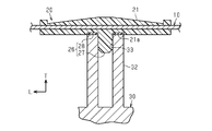
- (A) is a cross-sectional view taken along the line 3a-3a of FIG. 1, and (b) is a cross-sectional view taken along the line 3b-3b of FIG.
- FIG. 5 is a cross-sectional view taken along the line 4-4 of FIG.
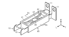
- (A) is a cross-sectional view taken along the line 6a-6a of FIG. 5, and (b) is a cross-sectional view taken along the line 6b-6b of FIG.
- the bus bar 10 is formed of a metal plate material such as copper or aluminum, and has a long plate shape. At one end of the bus bar 10, a connecting portion 11 electrically connected to another component is bent and formed.
- the bus bar 10 is assembled to a housing 30 made of a metal material such as aluminum. Note that FIG. 1 shows only a part of the housing 30.
- the longitudinal direction of the bus bar 10 will be simply described as the longitudinal direction L
- the width direction of the bus bar 10 will be simply described as the width direction W
- the thickness direction of the bus bar 10 will be simply described as the thickness direction T.
- a covering member 20 that covers the outer peripheral surface of the bus bar 10 over the entire circumference is provided at the central portion of the bus bar 10 in the longitudinal direction L.
- the covering member 20 of the present embodiment has a main body portion 21 and an elastic portion 28.
- the main body 21 is formed of a hard synthetic resin material, extends along the longitudinal direction L, and covers the bus bar 10.
- resin material constituting the main body 21 PA6 (polyamide 6) resin, PA66 (polyamide 66) resin, PPS (polyphenylene sulfide) resin, and PBT (polybutylene terephthalate) resin having excellent thermal conductivity are preferable.
- each lightening portion 24 has a plan view table shape, and a part of both sides of the bus bar 10 in the thickness direction T is exposed.
- a plurality of (8 in total) lightening portions 25 are provided inside the lightening portion 24 in the longitudinal direction L of the main body portion 21.
- Each lightening portion 25 has a right-angled triangular shape in a plan view, and a part of both sides of the bus bar 10 in the thickness direction T is exposed.
- a cylindrical collar 23 formed of a metal material such as aluminum is fixed to each mounting portion 22.
- the mounting portion 22 is formed with a hole 22a that penetrates the mounting portion 22 along the thickness direction T.
- the collar 23 is fixed inside the hole 22a.
- an annular recess 21a is provided on the outer periphery of the protrusion 27 in the main body 21.
- the recess 21a is provided with a disk-shaped elastic portion 28 formed of a resin material softer than the main body portion 21 and having a central hole.
- the elastic portion 28 is flush with the back surface of the main body portion 21.
- an elastomer having excellent heat resistance such as silicone is preferable.
- the main body 21 is integrally molded with the bus bar 10 and the collar 23 by inserting the bus bar 10 and the collar 23 into the molding die and injecting the molten resin into the cavity (both not shown) in the molding die.
- the lightening portions 24 and 25 are formed by clamps (not shown) sandwiching both sides of the bus bar 10 in the thickness direction T.
- the elastic portion 28 becomes the main body portion 21 by inserting the main body portion 21 integrally molded with the bus bar 10 and the collar 23 into the molding die and injecting the molten resin into the cavity (both not shown) in the molding die. Is molded integrally with.
- the second support portion 32 protrudes from the housing 30.
- the protrusion 27 is fitted in a fitting recess 33 that opens to the top surface of the second support 32.
- the bus bar 10 is positioned with respect to the housing 30.
- the bolt 35 is inserted through the collar 23 of the mounting portion 22.
- the first support portion 31 protrudes from the housing 30.
- the bolt 35 is screwed into the female screw hole 31a that opens on the top surface of the first support portion 31.
- the bus bar 10 is fixed to the housing 30.
- the elastic portion 28 is sandwiched between the main body portion 21 and the end surface of the second support portion 32.
- the protruding portion 27 and the elastic portion 28 of the main body portion 21 form a contact portion 26 in contact with the housing 30.
- the surface of the main body 21 of the covering member 20 is closer to the contact portion 26 in both the longitudinal direction L and the width direction W so that the distance from the bus bar 10 increases. It is tilted. As a result, the thickness of the covering member 20 increases as it approaches the contact portion 26 in both the longitudinal direction L and the width direction W. That is, the thickness of the covering member 20 in the contact portion 26 is larger than the thickness of the peripheral portion of the contact portion 26.
- the heat dissipation structure of the bus bar 10 includes a bus bar 10, a covering member 20 formed of a resin material and covering the bus bar 10, and a housing 30 formed of a metal material.
- the covering member 20 has a contact portion 26 that contacts the housing 30, and is integrally formed with the bus bar 10 by inserting the bus bar 10.
- the covering member 20 formed of the resin material is integrally molded with the bus bar 10 by inserting the bus bar 10, there is almost no gap between the bus bar 10 and the covering member 20. Therefore, the heat of the bus bar 10 is easily transferred directly to the covering member 20. Then, the heat transferred in this way is transferred to the housing 30 via the contact portion 26 of the covering member 20. Therefore, the heat dissipation of the bus bar 10 can be improved.
- the thickness of the covering member 20 in the contact portion 26 is larger than the thickness of the peripheral portion of the contact portion 26. Further, the thickness of the covering member 20 increases as it approaches the contact portion 26.
- the heat transferred from the bus bar 10 to the covering member 20 is directed from the peripheral portion of the contact portion 26 to the contact portion 26 which can store a large amount of heat due to its relatively large thickness. Will move. As a result, a large amount of heat can be released to the housing 30 via the contact portion 26.
- the contact portion 26 has a protrusion 27 that protrudes toward the housing 30. Further, the housing 30 has a fitting recess 33 into which the protrusion 27 is fitted.
- the covering member 20 and the bus bar 10 can be positioned with respect to the housing 30 by fitting the protrusion 27 provided in the contact portion 26 into the fitting recess 33 of the housing 30. ..
- the contact area between the contact portion 26 and the housing 30 is increased by adding the protrusion 27 and the fitting recess 33, the heat dissipation of the bus bar 10 can be further improved.
- the covering member 20 has a main body portion 21 that covers the bus bar 10 and an elastic portion 28 that is formed of a resin material softer than the main body portion 21 and is provided between the main body portion 21 and the housing 30. doing.
- the bus bar 10 and the covering member 20 can be assembled to the housing 30 in a state where the elastic portion 28 sandwiched between the covering member 20 and the housing 30 is elastically deformed. As a result, it is possible to prevent a gap from being generated between the covering member 20 and the housing 30. Therefore, the heat of the covering member 20 can be effectively transferred to the housing 30.
- a pair of bus bars 10 are arranged side by side in parallel. Specifically, a pair of bus bars 10 are arranged so as to face each other in their thickness direction T.
- the covering member 40 is integrally molded with the pair of bus bars 10.
- the covering member 40 has a rectangular tubular frame portion 41 and a plate portion 42 provided inside the frame portion 41.
- the pair of long side portions of the frame portion 41 covers the outer peripheral surfaces of the pair of bus bars 10 over the entire circumference.
- the plate portion 42 is located at the center of the frame portion 41 in the width direction W, and is connected to the entire inner side surface of the frame portion 41.
- a contact portion 46 that contacts the top surface of the support portion 51 that protrudes from the housing 50 is provided at the central portion on the back surface of the plate portion 42. .. That is, the contact portion 46 is provided between the bus bars 10 adjacent to each other.
- the housing 50 is made of a metal material such as aluminum in the same manner as the housing 30 of the first embodiment.
- a columnar convex portion 43 is projected from a portion of the surface of the plate portion 42 corresponding to the contact portion 46. That is, the thickness of the covering member 40 in the contact portion 46 is larger than the thickness of the peripheral portion of the contact portion 46.
- a pair of ribs 44 extending along a pair of diagonal lines of the frame portion 41 are provided on the surface of the plate portion 42.
- the covering member 40 of the present embodiment is not provided with a configuration corresponding to the elastic portion 28 illustrated in the first embodiment.
- the covering member 40 is integrally molded with the pair of bus bars 10.
- the pair of bus bars 10 are integrated via the covering member 40. Therefore, it is possible to achieve both improvement in heat dissipation of the bus bar 10 and improvement in workability for assembling to the housing 50.
- the contact portion 46 is provided between the bus bars 10 adjacent to each other.
- the contact portion 46 is provided between the bus bars 10 adjacent to each other, the portions of the housing 50 to which the contact portion 46 is contacted can be aggregated. Therefore, the structure of the covering member 40 and the housing 50 can be simplified.
- the number and shape of the lightening portions 24 may be changed as appropriate. Further, the lightening portion 24 can be omitted.
- the number and shape of the lightening portions 25 may be changed as appropriate. Further, the lightening portion 25 can be omitted.
- a pair of contact portions 46 may be provided corresponding to the pair of bus bars 10.
- the covering member 40 may be integrally molded with three or more bus bars 10.
- the elastic portion 28 of the first embodiment can be omitted.
- the structure corresponding to the elastic portion 28 illustrated in the first embodiment may be attached to the back surface of the plate portion 42. That is, the elastic portion does not have to be integrally formed with the main body portion of the covering member.
- the thickness of the main body 21 of the covering member 20 can be made constant. Further, in the second embodiment, the convex portion 43 and the rib 44 can be omitted from the plate portion 42 of the covering member 40.
Landscapes
- Engineering & Computer Science (AREA)
- Architecture (AREA)
- Civil Engineering (AREA)
- Structural Engineering (AREA)
- Physics & Mathematics (AREA)
- Thermal Sciences (AREA)
- Microelectronics & Electronic Packaging (AREA)
- Cooling Or The Like Of Electrical Apparatus (AREA)
- Insulated Conductors (AREA)
- Connection Or Junction Boxes (AREA)
- Connector Housings Or Holding Contact Members (AREA)
Abstract
バスバーの放熱構造は、バスバーと、樹脂材料により形成され、バスバーを被覆する被覆部材と、金属材料により形成された筐体とを備えている。被覆部材は、筐体に接触する接触部を有し、バスバーをインサートしてバスバーと一体に成形されている。
Description
本開示は、バスバーの放熱構造に関する。
特許文献1は、バスバーと、バスバーが固定されるケースとを備える電気接続箱を開示している。特許文献1に記載の電気接続箱においては、バスバーが熱伝導性材料からなるケースに固定されている。このため、バスバーの熱がバスバーとケースとの接触部分を介してケースの外に放出される。
ところで、特許文献1に記載の電気接続箱では、バスバー及びケースが各別に形成されて互いに組み付けられている。そのため、組み付け誤差などの製造誤差によってバスバーとケースとの間に隙間が生じるおそれがある。その結果、バスバーとケースとの接触面積が少なくなることでバスバーからケースへの熱伝達性、ひいてはバスバーの放熱性が損なわれるおそれがある。
本開示の目的は、バスバーの放熱性を向上できるバスバーの放熱構造を提供することにある。
上記目的を達成するためのバスバーの放熱構造は、バスバーと、樹脂材料により形成され、前記バスバーを被覆する被覆部材と、金属材料により形成された筐体と、を備え、前記被覆部材は、前記筐体に接触する接触部を有し、前記バスバーをインサートして前記バスバーと一体に成形されている。
以下、図1~図4を参照して、バスバーの放熱構造の第1実施形態について説明する。
図1、図2(a)及び図2(b)に示すように、バスバー10は、銅やアルミニウムなどの金属板材によって形成されており、長尺板状をなしている。バスバー10の一端部には、他の部品に電気的に接続される接続部11が屈曲して形成されている。
図1に示すように、バスバー10は、アルミニウムなどの金属材料によって形成された筐体30に組み付けられる。なお、図1においては、筐体30の一部のみを示している。
以降において、バスバー10の長手方向を単に長手方向Lと記載し、バスバー10の幅方向を単に幅方向Wと記載し、バスバー10の厚さ方向を単に厚さ方向Tと記載して説明する。
バスバー10の長手方向Lの中央部には、バスバー10の外周面を全周にわたって被覆する被覆部材20が設けられている。本実施形態の被覆部材20は、本体部21及び弾性部28を有している。
本体部21は、硬質の合成樹脂材料によって形成され、長手方向Lに沿って延在するとともにバスバー10を被覆している。本体部21を構成する樹脂材料としては、熱伝導性に優れたPA6(ポリアミド6)樹脂、PA66(ポリアミド66)樹脂、PPS(ポリフェニレンサルファイド)樹脂、及びPBT(ポリブチレンテレフタレート)樹脂が好ましい。
本体部21の長手方向Lの両端部には、幅方向Wにおいて互いに反対方向に向かって突出する2つの取付部22がそれぞれ設けられている。
図2(a)及び図2(b)に示すように、本体部21の長手方向Lの両端部には、複数(合計8つ)の肉抜き部24が設けられている。各肉抜き部24は、平面視台形状をなしており、バスバー10の厚さ方向Tの両面の一部を露出させている。
本体部21の長手方向Lにおける上記肉抜き部24よりも内側には、複数(合計8つ)の肉抜き部25が設けられている。各肉抜き部25は、平面視直角三角形状をなしており、バスバー10の厚さ方向Tの両面の一部を露出させている。
図2(a)、図2(b)及び図3(a)に示すように、各取付部22には、アルミニウムなどの金属材料によって形成された円筒状のカラー23が固定されている。
図3(a)に示すように、取付部22には、厚さ方向Tに沿って取付部22を貫通する孔22aが形成されている。上記カラー23は、孔22aの内部に固定されている。
図2(b)、図3(b)及び図4に示すように、本体部21の裏面、すなわち筐体30に対向する面には、筐体30に向かって突出する円柱状の突部27が設けられている。
図3(b)及び図4に示すように、本体部21における上記突部27の外周には、円環状の凹部21aが設けられている。凹部21aには、本体部21よりも軟質の樹脂材料により形成され、中心孔を有する円板状の弾性部28が設けられている。弾性部28は、本体部21の裏面と面一である。弾性部28を構成する樹脂材料としては、シリコーンなどの耐熱性に優れたエラストマーが好ましい。
バスバー10及びカラー23を成形型内にインサートし、成形型内のキャビティ(いずれも図示略)に溶融樹脂を射出することによって、本体部21がバスバー10及びカラー23と一体に成形される。このとき、バスバー10の厚さ方向Tの両面を挟むクランプ(図示略)によって上記肉抜き部24,25が形成される。
また、バスバー10及びカラー23と一体に成形された本体部21を成形型内にインサートし、成形型内のキャビティ(いずれも図示略)に溶融樹脂を射出することによって弾性部28が本体部21と一体に成形される。
図3(b)及び図4に示すように、第2支持部32は、筐体30から突出している。突部27は、第2支持部32の頂面に開口する嵌合凹部33に嵌合されている。これにより、筐体30に対してバスバー10が位置決めされている。
図3(a)に示すように、ボルト35が、取付部22のカラー23に挿通されている。第1支持部31は、筐体30から突出している。ボルト35は、第1支持部31の頂面に開口する雌ねじ孔31aに螺入されている。これにより、図1に示すように、バスバー10が筐体30に固定されている。また、弾性部28は、本体部21と第2支持部32の端面とによって挟まれている。
本実施形態においては、本体部21の突部27及び弾性部28が筐体30に接触する接触部26を構成している。
図3(b)及び図4に示すように、被覆部材20の本体部21の表面は、長手方向L及び幅方向Wの双方において接触部26に近づくほどバスバー10からの距離が大きくなるように傾斜している。これにより、被覆部材20の厚さは、長手方向L及び幅方向Wの双方において接触部26に近づくほど大きくなっている。すなわち、接触部26における被覆部材20の厚さは、接触部26の周囲の部分の厚さよりも大きい。
次に、本実施形態の作用効果について説明する。
(1)バスバー10の放熱構造は、バスバー10と、樹脂材料により形成され、バスバー10を被覆する被覆部材20と、金属材料により形成された筐体30とを備えている。被覆部材20は、筐体30に接触する接触部26を有し、バスバー10をインサートしてバスバー10と一体に成形されている。
こうした構成によれば、樹脂材料により形成された被覆部材20が、バスバー10をインサートしてバスバー10と一体に成形されているため、バスバー10と被覆部材20との間には隙間がほとんどない。このため、バスバー10の熱が被覆部材20に直接伝達されやすくなる。そして、こうして伝達された熱が被覆部材20の接触部26を介して筐体30に伝達されるようになる。したがって、バスバー10の放熱性を向上させることができる。
(2)接触部26における被覆部材20の厚さは、接触部26の周囲の部分の厚さよりも大きい。また、被覆部材20の厚さは、接触部26に近づくほど大きくなる。
こうした構成によれば、バスバー10から被覆部材20に伝達された熱は、接触部26の周囲の部分から、相対的に厚さが大きいことによって多くの熱を蓄えることのできる接触部26に向かって移動するようになる。これにより、接触部26を介して筐体30に多くの熱を放出することができる。
(3)接触部26は、筐体30に向かって突出する突部27を有している。また、筐体30は、突部27が嵌合される嵌合凹部33を有している。
こうした構成によれば、接触部26に設けられた突部27が筐体30の嵌合凹部33に嵌合されることによって、筐体30に対する被覆部材20及びバスバー10の位置決めを行うことができる。
また、突部27及び嵌合凹部33を追加することによって接触部26と筐体30との接触面積が大きくなることから、バスバー10の放熱性を一層向上させることができる。
(4)被覆部材20は、バスバー10を被覆する本体部21と、本体部21よりも軟質の樹脂材料により形成され、本体部21と筐体30との間に設けられる弾性部28とを有している。
こうした構成によれば、被覆部材20と筐体30との間に挟まれた弾性部28を弾性変形させた状態で、バスバー10及び被覆部材20を筐体30に組み付けることができる。これにより、被覆部材20と筐体30との間に隙間が生じることを抑制できる。したがって、被覆部材20の熱を筐体30に対して効果的に伝達することができる。
<第2実施形態>
以下、図5及び図6を参照して、第2実施形態について第1実施形態との相違点を中心に説明する。
以下、図5及び図6を参照して、第2実施形態について第1実施形態との相違点を中心に説明する。
図5に示すように、本実施形態では、一対のバスバー10が平行に並んで配置されている。具体的には、一対のバスバー10がそれらの厚さ方向Tにおいて対向して配置されている。
図5、図6(a)及び図6(b)に示すように、被覆部材40は、一対のバスバー10と一体に成形されている。
被覆部材40は、長方形筒状のフレーム部41と、フレーム部41の内側に設けられた板部42とを有している。フレーム部41の一対の長辺部分は、一対のバスバー10の外周面を全周にわたって被覆している。板部42は、フレーム部41の幅方向Wの中央に位置しており、フレーム部41の内側面全体に連結されている。
図6(a)及び図6(b)に示すように、板部42の裏面における中央部には、筐体50から突出する支持部51の頂面に接触する接触部46が設けられている。すなわち、接触部46は、互いに隣り合うバスバー10同士の間に設けられている。なお、筐体50は、第1実施形態の筐体30と同様にしてアルミニウムなどの金属材料によって形成されている。
板部42の表面における接触部46に対応する部分には、円柱状の凸部43が突設されている。すなわち、接触部46における被覆部材40の厚さは、接触部46の周囲の部分の厚さよりも大きい。
図5に示すように、板部42の表面には、フレーム部41の一対の対角線に沿ってそれぞれ延びる一対のリブ44が設けられている。
なお、本実施形態の被覆部材40には、第1実施形態において例示した弾性部28に相当する構成が設けられていない。
次に、本実施形態の作用効果について説明する。
(5)被覆部材40は、一対のバスバー10と一体に成形されている。
こうした構成によれば、被覆部材40を介して一対のバスバー10が一体化される。したがって、バスバー10の放熱性の向上と筐体50への組み付け作業性の向上との両立を図ることができる。
(6)接触部46は、互いに隣り合うバスバー10同士の間に設けられている。
こうした構成によれば、互いに隣り合うバスバー10同士の間に接触部46が設けられているため、筐体50における接触部46が接触される部位を集約できる。したがって、被覆部材40及び筐体50の構造を簡単にできる。
<変更例>
上記実施形態は、例えば以下のように変更して実施することもできる。本実施形態及び以下の変更例は、技術的に矛盾しない範囲で互いに組み合わせて実施することができる。
上記実施形態は、例えば以下のように変更して実施することもできる。本実施形態及び以下の変更例は、技術的に矛盾しない範囲で互いに組み合わせて実施することができる。
・肉抜き部24の数や形状を適宜変更してもよい。また、肉抜き部24を省略することもできる。
・肉抜き部25の数や形状を適宜変更してもよい。また、肉抜き部25を省略することもできる。
・第2実施形態において、一対のバスバー10にそれぞれ対応して一対の接触部46を設けるようにしてもよい。
・第2実施形態において、被覆部材40は、3つ以上のバスバー10と一体に成形されるものであってもよい。
・第1実施形態の弾性部28を省略することもできる。
・第1実施形態において例示した弾性部28に相当する構成を板部42の裏面に貼着するようにしてもよい。すなわち、弾性部は、被覆部材の本体部と一体に成形されていなくてもよい。
・第1実施形態の突部27を省略することもできる。この場合、筐体30の嵌合凹部33を省略すればよい。
・第1実施形態において、被覆部材20の本体部21の厚さを一定にすることもできる。また、第2実施形態において、被覆部材40の板部42から凸部43やリブ44を省略することもできる。
Claims (7)
- バスバーと、
樹脂材料により形成され、前記バスバーを被覆する被覆部材と、
金属材料により形成された筐体と、を備え、
前記被覆部材は、前記筐体に接触する接触部を有し、前記バスバーをインサートして前記バスバーと一体に成形されている、
バスバーの放熱構造。 - 前記接触部における前記被覆部材の厚さは、前記接触部の周囲の部分の厚さよりも大きい、
請求項1に記載のバスバーの放熱構造。 - 前記被覆部材の厚さは、前記接触部に近づくほど大きくなる、
請求項2に記載のバスバーの放熱構造。 - 前記接触部は、前記筐体に向かって突出する突部を有しており、
前記筐体は、前記突部が嵌合される嵌合凹部を有している、
請求項1~請求項3のいずれか一項に記載のバスバーの放熱構造。 - 前記被覆部材は、前記バスバーを被覆する本体部と、前記本体部よりも軟質の樹脂材料により形成され、前記本体部と前記筐体との間に設けられる弾性部とを有している、
請求項1~請求項4のいずれか一項に記載のバスバーの放熱構造。 - 前記バスバーは複数のバスバーのうちの1つであり、
前記被覆部材は、前記複数のバスバーと一体に成形されている、
請求項1~請求項5のいずれか一項に記載のバスバーの放熱構造。 - 前記接触部は、互いに隣り合う前記バスバー同士の間に設けられている、
請求項6に記載のバスバーの放熱構造。
Priority Applications (2)
| Application Number | Priority Date | Filing Date | Title |
|---|---|---|---|
| US17/436,654 US20220190578A1 (en) | 2019-03-13 | 2020-01-31 | Bus bar heat dissipation structure |
| CN202080019032.XA CN113545178B (zh) | 2019-03-13 | 2020-01-31 | 汇流条的散热结构 |
Applications Claiming Priority (2)
| Application Number | Priority Date | Filing Date | Title |
|---|---|---|---|
| JP2019-045401 | 2019-03-13 | ||
| JP2019045401A JP2020149827A (ja) | 2019-03-13 | 2019-03-13 | バスバーの放熱構造 |
Publications (1)
| Publication Number | Publication Date |
|---|---|
| WO2020183971A1 true WO2020183971A1 (ja) | 2020-09-17 |
Family
ID=72426789
Family Applications (1)
| Application Number | Title | Priority Date | Filing Date |
|---|---|---|---|
| PCT/JP2020/003578 Ceased WO2020183971A1 (ja) | 2019-03-13 | 2020-01-31 | バスバーの放熱構造 |
Country Status (4)
| Country | Link |
|---|---|
| US (1) | US20220190578A1 (ja) |
| JP (1) | JP2020149827A (ja) |
| CN (1) | CN113545178B (ja) |
| WO (1) | WO2020183971A1 (ja) |
Cited By (1)
| Publication number | Priority date | Publication date | Assignee | Title |
|---|---|---|---|---|
| WO2024225096A1 (ja) * | 2023-04-26 | 2024-10-31 | 株式会社オートネットワーク技術研究所 | 電気機器 |
Families Citing this family (1)
| Publication number | Priority date | Publication date | Assignee | Title |
|---|---|---|---|---|
| KR20240175641A (ko) * | 2023-06-13 | 2024-12-20 | 주식회사 엘지에너지솔루션 | 버스바 조립체 및 이를 포함하는 전지 팩 |
Citations (1)
| Publication number | Priority date | Publication date | Assignee | Title |
|---|---|---|---|---|
| JP2013070028A (ja) * | 2011-09-07 | 2013-04-18 | Hitachi Automotive Systems Ltd | 電子制御装置 |
Family Cites Families (7)
| Publication number | Priority date | Publication date | Assignee | Title |
|---|---|---|---|---|
| US6024589A (en) * | 1997-05-14 | 2000-02-15 | Hewlett-Packard Company | Power bus bar for providing a low impedance connection between a first and second printed circuit board |
| JP5054991B2 (ja) * | 2007-02-01 | 2012-10-24 | 三菱重工業株式会社 | バスバー接続構造およびインバータ一体型電動圧縮機 |
| JP5634691B2 (ja) * | 2009-08-18 | 2014-12-03 | 矢崎総業株式会社 | バスバ |
| JP4935883B2 (ja) * | 2009-11-27 | 2012-05-23 | 株式会社デンソー | バスバーアッセンブリ |
| JP5550927B2 (ja) * | 2010-01-29 | 2014-07-16 | 本田技研工業株式会社 | 電力変換装置 |
| JP5803405B2 (ja) * | 2011-08-10 | 2015-11-04 | 株式会社オートネットワーク技術研究所 | バスバーカバー、及びカバー付きバスバー |
| JP6618504B2 (ja) * | 2017-04-28 | 2019-12-11 | 矢崎総業株式会社 | バスバー及びバスバーの製造方法 |
-
2019
- 2019-03-13 JP JP2019045401A patent/JP2020149827A/ja active Pending
-
2020
- 2020-01-31 US US17/436,654 patent/US20220190578A1/en not_active Abandoned
- 2020-01-31 CN CN202080019032.XA patent/CN113545178B/zh active Active
- 2020-01-31 WO PCT/JP2020/003578 patent/WO2020183971A1/ja not_active Ceased
Patent Citations (1)
| Publication number | Priority date | Publication date | Assignee | Title |
|---|---|---|---|---|
| JP2013070028A (ja) * | 2011-09-07 | 2013-04-18 | Hitachi Automotive Systems Ltd | 電子制御装置 |
Cited By (3)
| Publication number | Priority date | Publication date | Assignee | Title |
|---|---|---|---|---|
| WO2024225096A1 (ja) * | 2023-04-26 | 2024-10-31 | 株式会社オートネットワーク技術研究所 | 電気機器 |
| JPWO2024225096A1 (ja) * | 2023-04-26 | 2024-10-31 | ||
| JP7773706B2 (ja) | 2023-04-26 | 2025-11-20 | 株式会社オートネットワーク技術研究所 | 電気機器 |
Also Published As
| Publication number | Publication date |
|---|---|
| JP2020149827A (ja) | 2020-09-17 |
| CN113545178B (zh) | 2024-03-19 |
| US20220190578A1 (en) | 2022-06-16 |
| CN113545178A (zh) | 2021-10-22 |
Similar Documents
| Publication | Publication Date | Title |
|---|---|---|
| JP7001960B2 (ja) | 回路構成体 | |
| JP5211364B2 (ja) | 半導体装置 | |
| JP5871044B1 (ja) | 端子モジュール | |
| CN110999560B (zh) | 树脂密封型车载电子控制装置 | |
| JP6548146B2 (ja) | 回路構成体 | |
| JP6866648B2 (ja) | 電子機器の筐体 | |
| CN114072889B (zh) | 电容器 | |
| US9491844B2 (en) | Electronic device | |
| WO2020183971A1 (ja) | バスバーの放熱構造 | |
| JP2019216503A (ja) | 電気接続箱 | |
| KR101514797B1 (ko) | 퓨즈 유닛 | |
| US11777267B2 (en) | Connector assembly | |
| JP5950013B2 (ja) | 端子モジュール | |
| JP6278997B2 (ja) | 電子機器ユニット | |
| US20150003071A1 (en) | Illuminating device and manufacturing method thereof | |
| WO2015045623A1 (ja) | コネクタ | |
| JP7271247B2 (ja) | 車両灯具用光源ユニット及びその製造方法 | |
| US12199374B2 (en) | Connector and mounting structure | |
| JP7234847B2 (ja) | 電子モジュール | |
| JP5506858B2 (ja) | 回転電機 | |
| KR20080088880A (ko) | 전구 소켓 | |
| US20250372926A1 (en) | Connector with built-in ferrite core | |
| KR102861641B1 (ko) | 커넥터 | |
| JP2018098002A (ja) | ヒーター抵抗器 | |
| JPS5833659Y2 (ja) | 配線ダクトのセンタ−フィ−ドインジョイナ |
Legal Events
| Date | Code | Title | Description |
|---|---|---|---|
| 121 | Ep: the epo has been informed by wipo that ep was designated in this application |
Ref document number: 20769397 Country of ref document: EP Kind code of ref document: A1 |
|
| NENP | Non-entry into the national phase |
Ref country code: DE |
|
| 122 | Ep: pct application non-entry in european phase |
Ref document number: 20769397 Country of ref document: EP Kind code of ref document: A1 |