WO2020179935A1 - 回転駆動装置 - Google Patents
回転駆動装置 Download PDFInfo
- Publication number
- WO2020179935A1 WO2020179935A1 PCT/JP2020/010077 JP2020010077W WO2020179935A1 WO 2020179935 A1 WO2020179935 A1 WO 2020179935A1 JP 2020010077 W JP2020010077 W JP 2020010077W WO 2020179935 A1 WO2020179935 A1 WO 2020179935A1
- Authority
- WO
- WIPO (PCT)
- Prior art keywords
- gear
- rotation
- operating
- transmission gear
- winding
- Prior art date
- Legal status (The legal status is an assumption and is not a legal conclusion. Google has not performed a legal analysis and makes no representation as to the accuracy of the status listed.)
- Ceased
Links
Images




Classifications
-
- B—PERFORMING OPERATIONS; TRANSPORTING
- B61—RAILWAYS
- B61L—GUIDING RAILWAY TRAFFIC; ENSURING THE SAFETY OF RAILWAY TRAFFIC
- B61L29/00—Safety means for rail/road crossing traffic
- B61L29/04—Gates for level crossings
-
- F—MECHANICAL ENGINEERING; LIGHTING; HEATING; WEAPONS; BLASTING
- F16—ENGINEERING ELEMENTS AND UNITS; GENERAL MEASURES FOR PRODUCING AND MAINTAINING EFFECTIVE FUNCTIONING OF MACHINES OR INSTALLATIONS; THERMAL INSULATION IN GENERAL
- F16C—SHAFTS; FLEXIBLE SHAFTS; ELEMENTS OR CRANKSHAFT MECHANISMS; ROTARY BODIES OTHER THAN GEARING ELEMENTS; BEARINGS
- F16C1/00—Flexible shafts; Mechanical means for transmitting movement in a flexible sheathing
- F16C1/26—Construction of guiding-sheathings or guiding-tubes
-
- F—MECHANICAL ENGINEERING; LIGHTING; HEATING; WEAPONS; BLASTING
- F16—ENGINEERING ELEMENTS AND UNITS; GENERAL MEASURES FOR PRODUCING AND MAINTAINING EFFECTIVE FUNCTIONING OF MACHINES OR INSTALLATIONS; THERMAL INSULATION IN GENERAL
- F16H—GEARING
- F16H25/00—Gearings comprising primarily only cams, cam-followers and screw-and-nut mechanisms
- F16H25/04—Gearings comprising primarily only cams, cam-followers and screw-and-nut mechanisms for conveying rotary motion
- F16H25/06—Gearings comprising primarily only cams, cam-followers and screw-and-nut mechanisms for conveying rotary motion with intermediate members guided along tracks on both rotary members
-
- G—PHYSICS
- G05—CONTROLLING; REGULATING
- G05G—CONTROL DEVICES OR SYSTEMS INSOFAR AS CHARACTERISED BY MECHANICAL FEATURES ONLY
- G05G11/00—Manually-actuated control mechanisms provided with two or more controlling members co-operating with one single controlled member
-
- G—PHYSICS
- G05—CONTROLLING; REGULATING
- G05G—CONTROL DEVICES OR SYSTEMS INSOFAR AS CHARACTERISED BY MECHANICAL FEATURES ONLY
- G05G7/00—Manually-actuated control mechanisms provided with one single controlling member co-operating with one single controlled member; Details thereof
- G05G7/02—Manually-actuated control mechanisms provided with one single controlling member co-operating with one single controlled member; Details thereof characterised by special provisions for conveying or converting motion, or for acting at a distance
- G05G7/10—Manually-actuated control mechanisms provided with one single controlling member co-operating with one single controlled member; Details thereof characterised by special provisions for conveying or converting motion, or for acting at a distance specially adapted for remote control
Definitions
- the present invention relates to a rotary drive device.
- An object of the present invention is to provide a rotary drive device capable of operating the operating shaft in one direction or the other direction by operating the operation wire in one direction.
- the rotation drive device of the present invention includes a rotation operation unit, a drive unit for driving the rotation operation unit, an operation wire for operating the drive unit, and an outer tube for covering the outer periphery of the operation wire.
- the rotation operating unit has an operating shaft and an operating gear that rotates the operating shaft in one direction
- the driving unit has a driving gear that is rotated by driving the driving unit.
- the drive device is connected to an intermediate gear that is connected to the operating gear to rotate the operating shaft in another direction, a transmission gear that transmits the rotation of the driving gear, and the operating gear by moving the transmission gear.
- the outer tube has a switching member that switches between a first connection state that rotates the operating shaft in one direction and a second connection state that rotates the operating shaft in the other direction by connecting to the intermediate gear.
- the operating shaft is rotated in one direction or the other direction by connecting to the member and operating the outer tube.
- the operation shaft can be operated in one direction or the other direction by operating the operation wire in one direction.
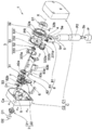
- FIG. 2 is an exploded perspective view of the rotary drive device shown in FIG. 1. It is the schematic which shows the state which the winding member used for the rotary driving device of FIG. 2 and a rotary member are close to each other.
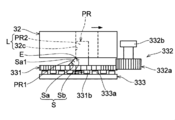
- FIG. 5 is a schematic view showing a state in which the winding member and the rotating member are slightly separated from each other by the separating mechanism from the state shown in FIG.
- FIG. 5 is a schematic view showing a state in which the winding member and the rotating member are separated from each other by the separating mechanism from the state shown in FIG. 4, and the rotating member and the rotation transmitting member are engageable with each other. From the state shown in FIG.
- FIG. 5 is a schematic view which shows the state which the rotating member and the rotation transmission member engaged with each other are rotating in conjunction with each other.
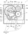
- FIG. 3 is a schematic diagram showing a first connection state in which a transmission gear is connected to an operation gear in the rotary drive device shown in FIG. 2.
- FIG. 3 is a schematic diagram showing a second connection state in which a transmission gear is connected to an intermediate gear in the rotary drive device shown in FIG. 2.
- the rotary drive device according to the embodiment of the present invention will be described with reference to the drawings.
- the following embodiments are merely examples, and the rotary drive device of the present invention is not limited to the following embodiments.
- an example in which the rotation driving device is applied to the lifting member operating device will be described.
- the rotary drive device of the present invention may be applied to a device other than the elevating member operating device.
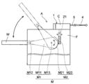
- the elevating member operating device A includes an elevating mechanism M provided with an elevating member W and a rotation driving device 1 connected to the elevating mechanism M.
- the elevating/lowering member operating device A operates the elevating/lowering member W by the driving force generated by the rotation driving device 1.
- the elevating member W operated by the elevating member operating device A is a shielding rod in this embodiment, but may be another shielding body such as a protective fence or a protective rope.
- the lifting member W is configured to rotate around a predetermined axis.
- the elevating member W is configured to rotate about a horizontal axis, but may rotate about a vertical axis.
- the elevating member W is not limited to the one that rotates around a predetermined axis, and may be configured to slide along the horizontal direction or the vertical direction.
- the elevating mechanism M elevates and lowers the elevating member W by the driving force generated by the rotary drive device 1.
- the elevating mechanism M converts the operating force output from the rotation drive device 1 into an elevating operation of the elevating member W to elevate the elevating member W.
- the elevating mechanism M transmits a rotational force from the rotation driving device 1 and elevates and elevates the elevating member W by the rotational force.
- the elevating mechanism M includes an elevating member W provided on the base F, an operating member M1 for moving the elevating member W to an initial position and an operation ending position, and a drive generated by a rotation driving device 1. And a transmission mechanism M2 for transmitting the force to the actuating member M1.
- the initial position of the elevating/lowering member W is, as shown by the solid line in FIG. 1, from the inside of the base F to the outside through the vertically extending opening provided in the base F which is the housing. It is a position that extends horizontally to.
- the operation end position of the elevating member W is a position where the elevating member W reaches a predetermined position on the upper side of the substrate F, as shown by a two-dot chain line in FIG. After moving to the operation end position, the elevating member W moves again to the initial position, and moves up and down between the initial position which is the descent position and the operation end position which is the ascending position.
- the initial position and the operation end position of the elevating member W are appropriately changed according to the operating range and the operating method of the elevating member W.
- the structure of the operating member M1 is not particularly limited as long as the elevating member W can be moved between the initial position and the operating end position by using the driving force transmitted by the transmission mechanism M2.
- the operating member M1 operates with a connecting portion M12 connected to the base F and the elevating member W, and an operating arm M11 for moving the elevating member W connected to the connecting portion M12. It has a shaft portion M13 that serves as a rotation axis of the arm M11 and an elevating member W.
- the actuating member M1 may be configured to convert the rotational movement output by the transmission mechanism M2 into a linear movement to linearly move the lifting member W, or the transmission mechanism.
- the rotation operation output by M2 may be transmitted as a rotation operation around the rotation axis of the elevating member W. Further, when the operating force due to the linear motion is output from the transmission mechanism M2, the operating member M1 may transmit the operating force due to the linear motion from the transmission mechanism M2 as a linear motion or as a rotary motion. Good.
- the transmission mechanism M2 transmits the driving force generated by the rotary drive device 1 to the operating member M1.
- the transmission mechanism M2 transmits the rotational force generated by the rotary drive device 1 to the operating member M1.
- the rotation drive device 1 may output an operation force other than the rotation operation such as a linear operation. In that case, the transmission mechanism M2 may transmit an operation force other than the rotation operation to the operating member M1.
- the structure of the transmission mechanism M2 is not particularly limited as long as the driving force generated by the rotary drive device 1 can be transmitted to the operating member M1.
- the transmission mechanism M2 includes a first transmission gear M21 connected to the operating member M1 and a second transmission gear M22 that meshes with the first transmission gear M21. ..
- the second transmission gear M22 is directly or indirectly connected to an operating shaft 21 (see FIG. 1) provided on the rotation drive device 1 side.
- the first transmission gear M21 is connected to the connecting portion M12, and the first transmission gear M21 rotates to operate the connected connecting portion M12 to operate the operating arm M11 to which the connecting portion M12 is connected.
- the elevating member W is moved up and down by rocking.
- the second transmission gear M22 meshes with the first transmission gear M21 to rotate the first transmission gear M21.
- the second transmission gear M22 is connected to the operating shaft 21 and rotates by the rotation of the operating shaft 21.
- the first transmission gear M21 is a sector gear and the second transmission gear M22 is a worm gear.
- the shape and structure of the first transmission gear M21 and the second transmission gear M22 are particularly limited as long as the operating member M1 can be moved via the second transmission gear M22 and the first transmission gear M21 by the rotation of the operating shaft 21. Not done.
- the combination of the first transmission gear M21 and the second transmission gear M22 can be appropriately selected from various gears such as a worm gear, a spur gear, and a bevel gear.
- the rotation drive device 1 is a device that drives an operation target such as an elevating member W.
- the object to be operated by the rotary drive device 1 is the lifting member W in the present embodiment, but is not limited to the lifting member W.
- the rotation driving device 1 covers the rotation operating unit 2, the driving unit 3 for driving the rotation operating unit 2, the operating wire 4 for operating the driving unit 3, and the outer periphery of the operating wire 4.
- the outer tube 5 is provided.
- the rotary operating unit 2 has an operating shaft 21 and an operating gear 22 that rotates the operating shaft 21.
- the drive unit 3 has a drive gear 31 that is rotated by driving the drive unit 3.
- the rotary drive device 1 includes an intermediate gear 6 that is connected to the operating gear 22 to rotate the operating shaft 21 in the other direction, and a transmission gear 7 that transmits the rotation of the drive gear 31. Have.
- the rotation drive device 1 rotates the operating shaft 21 in one direction by connecting with the operating gear 22 by moving the transmission gear 7, and the operating shaft 21 by connecting with the intermediate gear 6 in the other direction. It has a switching member 8 for switching to a second connection state in which it is rotated.
- a shaft member is used for the operating shaft 21 in the embodiment shown in the figure, a geared cable or a torque cable is used as a rotating shaft instead of the shaft member, and the rotating shaft is used as a driving force transmitted by the transmission gear 7.
- the object to be actuated may be actuated by being rotated by.
- the operating shaft 21 can be rotated as an output by operating the operating wire 4, and the operating shaft 21 is rotated by operating the operating wire 4 by operating the outer tube 5. Switch direction.
- a second connection state in which the transmission gear 7 and the operating gear 22 are connected by the switching member 8 operated by the outer tube 5 and a transmission gear 7 and the intermediate gear 6 are connected.
- the rotation direction of the operating shaft 21 is switched by switching the connection state of the transmission gear 7 between the connection state and the connection state.
- the rotary drive device 1 operates the operating target such as the elevating member W in two directions without separately providing an operating member for switching. The details of the operation of the rotary drive device 1 will be described later.
- the operation wire 4 operates the drive unit 3 in order to operate the rotation actuating unit 2.
- the structure of the operation wire 4 is not particularly limited as long as the drive unit 3 can be operated.
- the operation wire 4 is a flexible inner cable.
- the operation wire 4 is connected to the take-up member 32, and can be taken up by the take-up member 32 and unwound from the take-up member 32. By pulling, the operating force is transmitted to the winding member 32.
- the operation wire 4 has one end (not shown) connected to the winding member 32 and the other end having the operation wire operation portion P, and the other end side having the operation wire operation portion P is the case C (not shown).
- the first case member C1 and the second case member C2 are included in the structure).
- axis X a predetermined axis
- the outer tube 5 covers the outer circumference of the operation wire 4.
- the outer tube 5 is a tubular member having both ends open, and accommodates the operation wire 4 so that the operation wire 4 can move in the axial direction with respect to the outer tube 5.
- the outer tube 5 is operated to switch the rotation direction of the operating shaft 21.
- One end 5a of the outer tube 5 is connected to the switching member 8 (driven member 81 described later) and is located inside the case C, and the other end 5b of the outer tube 5 is located outside the case C.
- an outer tube operating portion P2 for operating the outer tube 5 is provided on the other end 5b side of the outer tube 5.
- the drive unit 3 is operated by the operation wire 4 to generate a driving force capable of operating the rotary operation unit 2.
- the drive unit 3 rotates the operating gear 22 by the rotational driving force of the drive gear 31 that is rotated by operating the operation wire 4.
- the structure of the drive unit 3 is not particularly limited as long as the operation gear 22 can be rotated by the rotational drive force of the drive gear 31 that is rotated by the operation of the operation wire 4.
- the drive unit 3 includes a winding member 32 that winds up and unwinds the operation wire 4, and a transmission member 33 that transmits the rotational operation of the winding member 32 to the drive gear 31. Equipped with.
- the take-up member 32 is configured so that one end of the operation wire 4 is connected and the operation wire 4 is pulled to rotate. When the operation wire 4 is pulled, the take-up member 32 rotates in one direction, and the operation wire 4 wound around the take-up member 32 is unwound from the take-up member 32. In the present embodiment, the take-up member 32 is urged by the take-up member urging member S1 in the direction of winding the operation wire 4.
- the structure of the winding member 32 is not particularly limited as long as it can be rotated by the operation of the operation wire 4 and the rotational movement can be transmitted to the drive gear 31.
- the winding member 32 is a drum rotatably provided with respect to the case C, and accommodates the winding groove 32a around which the operation wire 4 is wound and the winding member urging member S1. It has the accommodating part 32b.
- the take-up member urging member S1 urges the take-up member 32 in the direction in which the take-up member 32 winds the operation wire 4.
- the take-up member urging member S1 when the operation wire 4 is pulled and the take-up member 32 rotates so that the operation wire 4 is unwound from the take-up member 32, the urging force is accumulated in the take-up member urging member S1. Will be done.
- the winding member 32 rotates in the direction of winding the operation wire 4 due to the urging force accumulated in the winding member urging member S1, and the operation wire 4 returns to the initial position.
- the structure of the take-up member urging member S1 is not particularly limited as long as the take-up member 32 can be urged so that the take-up member 32 rotates in the direction in which the operation wire 4 is taken up.
- the winding member urging member S1 is a spiral spring.
- the winding member urging member S1 which is a spiral spring is accommodated in the accommodating portion 32b as a recess provided in one end surface of the winding member 32, one end is attached to the case C side, and the other end is the winding member. It is attached to 32.
- the winding member urging member S1 may be another urging member such as a spring as long as the winding member 32 can be urged to rotate in the direction in which the operation wire 4 is wound.
- the transmission member 33 transmits the rotational force of the winding member 32 rotated by the operation of the operation wire 4 to the drive gear 31.
- the structure of the transmission member 33 is not particularly limited as long as the rotational force of the winding member 32 that rotates by the operation of the operation wire 4 can be transmitted to the drive gear 31.
- the transmission member 33 transmits the rotational force in one direction of the winding member 32 to the drive gear 31 when the operation wire 4 is pulled, and the operation on the operation wire 4 is released so that the operation wire 4 is released.
- the rotational force in the other direction of the winding member 32 is not transmitted to the drive gear 31. Specifically, as shown in FIG.
- the transmission member 33 includes a rotating member 331 that rotates in the same direction as the winding member 32 rotates, and a load member 332 that applies a load to the rotation of the rotating member 331.
- a rotation transmission member 333 provided with an engagement/disengagement portion 333a capable of engaging/disengaging the rotation member 331, and a rotation member urging member S2 for urging the rotation member 331 toward the winding member 32 side.
- the winding member 32 rotates in the feeding direction of the operation wire 4.
- the rotating member 331 is separated from the winding member 32 in the axis X (see FIG. 2) direction, and the rotating member 331 rotates in the same direction as the winding member 32.
- the rotating member 331 engages with the rotation transmitting member 333 by being separated from the winding member 32 in the axis X direction, and rotates the rotation transmitting member 333 in the same direction as the rotating member 331.
- the rotation transmission member 333 rotates in the same direction as the rotation member 331
- the rotation of the rotation transmission member 333 causes the drive gear 31 to rotate.
- the rotating member 331 is configured to rotate in the same direction as the winding member 32 in accordance with the rotation of the winding member 32.
- the rotating member 331 is arranged coaxially with the winding member 32 and is rotatably provided in the case C.
- the rotating member 331 is rotatable relative to the winding member 32 at a predetermined angle, and is configured to rotate together with the winding member 32 after being rotated at a predetermined angle. ..
- the rotating member 331 is attached so as to be close to and separated from the winding member 32 in the axis X direction. As shown in FIG. 2, the rotating member 331 is urged toward the winding member 32 by the rotating member urging member S2. In the initial state in which the operation wire 4 is not operated, the rotating member 331 is located at a close position close to the winding member 32 side in the axis X direction by the urging force of the rotating member urging member S2 (FIG. 3). reference). As shown in FIGS. 3 to 6, the rotating member 331 has a rotating member urging member S2 while the winding member 32 rotates relative to the rotating member 331 by the separating mechanism S and the loose fitting mechanism L described later.
- the relative rotation between the winding member 32 and the rotating member 331 is not limited to the one in which the rotating member 331 rotates at a speed lower than the rotation speed of the winding member 32 when the winding member 32 rotates. The case where only the take-up member 32 rotates without rotating 331 is also included.
- the rotating member 331 is not limited to the structure shown in the drawing, but in the present embodiment, it is a gear having a tooth portion 331a on the outer periphery, and as will be described later, a protrusion PR protruding from the end surface on the winding member 32 side (FIG. 2). (See), and the end face on the rotation transmission member 333 side has a rotation member side engagement disengagement portion 331b (see FIGS. 3 to 6).
- the rotating member urging member S2 is provided between the end surface of the rotation transmitting member 333 and the end surface of the rotating member 331 that face each other, as shown in FIG.
- the position where the rotating member urging member S2 is installed is not particularly limited as long as it can urge the rotating member 331 toward the winding member 32.
- the rotating member urging member S2 may be provided between the end surface of the rotating member 331 and the end surface of the winding member 32 that face each other, and may urge the rotating member 331 toward the winding member 32 side. , May be provided at other positions.
- a coil spring is used as the rotating member urging member S2, but the structure of the rotating member urging member S2 is not particularly limited.
- the load member 332 is a member that applies a load to the rotating direction of the rotating member 331 to suppress the rotation in the rotating direction. By applying a load to the rotating member 331, the load member 332 suppresses the rotating member 331 from rotating at the same speed as the winding member 32 when the winding member 32 starts to rotate.
- the load member 332 may be a member that gives the rotating member 331 an action of increasing the driving force required for rotation with respect to the rotation of the rotating member 331, and is in a direction opposite to the rotation direction of the rotating member 331. It may be a member that gives the force of.
- the load member 332 is directly or indirectly connected to the rotating member 331.
- the structure of the load member 332 is not particularly limited as long as a load can be applied to the movement of the rotating member 331 in the rotation direction.
- the load member 332 has a load gear 332a that meshes with the tooth portion 331a of the rotating member 331 and a load portion 332b that applies a load to the load gear 332a.
- the load unit 332b is a rotary damper that applies a braking force against the rotation of the load gear 332a, and by applying a braking force against the rotation of the load gear 332a, the load unit 332b is opposite to the rotation direction of the rotating member 331.
- the tooth portion of the load gear 332a rotates in the moving range of the rotating member 331 in the axis X direction in consideration of the movement of the rotating member 331 in the axis X direction. It has a length in the axis X direction that can mesh with the tooth portion 331a of the member 331.
- a winding member 32 are provided with a loose fitting mechanism L capable of transitioning between an engaged state and a relative movement permitting state.
- the separation mechanism S separates the rotating member 331 from the winding member 32 in the axis X direction in order to engage the rotating member 331 with the rotation transmitting member 333.
- the separating mechanism S is connected to a guide portion Sa that guides the rotating member 331 in a direction relatively separated from the winding member 32 in the axis X direction, and a guide portion Sa. And a connecting portion Sb that relatively moves with each other.
- the guide portion Sa is connected to the connecting portion Sb when the operation wire 4 of the winding member 32 is rotated in the feeding direction, and is between the guide portion Sa and the connecting portion Sb when the winding member 32 is rotated in the feeding direction.
- the acting force is converted into a force that causes the rotating member 331 to separate from the winding member 32 in the axial X direction to separate the rotating member 331 from the winding member 32.
- the connecting portion Sb is guided along the guide portion Sa while being wound.
- the take-up member 32 and the rotary member 331 relatively rotate to separate the rotary member 331 from the take-up member 32.
- the guide portion Sa of the separation mechanism S is provided on the rotating member 331.
- the guide portion Sa is provided on the protrusion PR that protrudes toward the winding member 32.
- the guide portion Sa may be provided on the winding member 32.
- a protrusion having a guide portion may be provided so as to project from the winding member 32 toward the rotating member 331.
- the protrusion PR includes an axial protrusion PR1 having a guide portion Sa, and a fitting protrusion PR2 that fits into a loose fitting mechanism opening described later. have.
- the axial protrusion PR1 and the fitting protrusion PR2 are integrally provided adjacent to each other in the circumferential direction of the rotating member 331, but are separately provided separately in the circumferential direction. May be.
- the guide portion Sa of the separating mechanism S is the inclined surface Sa1 of the axial protrusion PR1.
- the inclined surface Sa1 of the axial protrusion PR1 is connected to, for example, when the winding member 32 rotates relative to the rotating member 331 due to the winding member 32 rotating relatively faster than the rotating member 331.
- the rotating member 331 may be inclined so as to be separated from the winding member 32 in the axis X direction.
- the inclined surface Sa1 provided on the axial protrusion PR1 protruding from the rotating member 331 advances in the rotational direction of the winding member 32 and the rotating member 331 that rotate in the feeding direction by the operation of the operation wire 4.
- the height of the rotating member 331 from the end face (distance from the end face in the axis X direction) is increased (see FIG. 2).
- a guide portion inclined surface
- the inclined surface advances to the side opposite to the rotation direction of the winding member 32 and the rotating member 331 that are rotated by the operation of the operation wire 4. Therefore, the winding member 32 may be inclined so as to increase the height from the end face (distance from the end face in the axis X direction).
- the height of the guide portion Sa in the axis X direction may be configured so that the rotation member 331 and the rotation transmission member 333 can be engaged with each other in the axis X direction.
- the connecting portion Sb is connected in contact with the guide portion Sa, and when the winding member 32 rotates in the feeding direction, the connecting portion Sb moves relative to the guide portion Sa, whereby the rotating member 331 is wound up by the winding member 32. And the rotating member 331 is brought closer to the rotation transmitting member 333 by separating the rotating member 331 in the axis X direction. As a result, the rotating member 331 engages with the rotation transmitting member 333 and transmits the rotation of the rotating member 331 to the rotation transmitting member 333.
- the connecting portion Sb is provided on the winding member 32 when the guide portion Sa is provided on the rotating member 331, and is provided on the rotating member 331 when the guide portion Sa is provided on the rotating member 331. .. In the present embodiment, the connecting portion Sb is provided on the winding member 32. In the present embodiment, as shown in FIGS. 3 to 6, the connecting portion Sb connected to the guide portion Sa is the edge portion E of the opening 32c into which the axial protrusion PR1 is inserted. When the connecting portion is provided on the rotating member 331 side, the connecting portion should be the edge portion of the opening provided on the rotating member 331 into which the axial protrusion PR1 protruding from the winding member 32 is inserted. Can be done.
- the structure of the connecting portion Sb is not particularly limited as long as the connecting portion Sb can move relative to the guide portion Sa by coming into contact with the guide portion Sa and rotating the winding member 32 in the feeding direction.
- a protrusion that engages with each other in the circumferential direction is provided on both end surfaces of the winding member 32 and the rotating member 331 that face each other, and a guide portion Sa is provided on one of the protrusions and is connected to the other protrusion.
- the part Sb may be provided.
- the loose fitting mechanism L is a mechanism that enables the winding member 32 and the rotating member 331 to transition between the engaged state and the relative movement allowable state.
- the winding member 32 and the rotating member 331 rotate relative to each other due to the difference in the rotation speed between the winding member 32 and the rotating member 331. It is in a state to do.
- the engaging state is such that the winding member 32 and the rotating member 331 are engaged in the rotational direction, so that the winding member 32 and the rotating member 331 are relative to each other. The rotation is suppressed, and the winding member 32 and the rotating member 331 are interlocked and rotate in the same direction.
- the separating mechanism S guides the connecting portion Sb to the guide portion Sa. ..
- the loose fitting mechanism L causes the rotating member 331 to be separated from the winding member 32.
- the rotation member 331 is brought into an engaged state.
- the rotation transmitting member 333 engaged with the rotating member 331 can rotate in the feeding direction in conjunction with the rotation of the winding member 32.
- the drive gear 31 is rotated, the operating shaft 21 is rotated via the transmission gear 22 and the like, and the operation target such as the elevating member W and the like is operated. ..
- the loose fitting mechanism L has a fitting protrusion PR2 protruding in the axis X direction and a free fitting mechanism opening for accommodating the fitting protrusion PR2 in the space.
- the free fitting mechanism opening is integrally formed with the opening 32c into which the axial protrusion PR1 is inserted.
- the fitting protrusion PR2 is free to allow the rotating member 331 and the winding member 32 to rotate relative to each other while the winding member 32 rotates at a predetermined rotation angle.
- the space in the opening of the fitting mechanism is loosely fitted.
- the fitting protrusion PR2 after the winding member 32 and the rotating member 331 are in a relative movement allowable state and the winding member 32 is rotated by a predetermined angle, as shown in FIGS. 5 and 6, the fitting protrusion PR2 is free. Engage in at least part of the fitting mechanism opening in a rotational direction.
- the fitting protrusion PR2 and the inner wall in the opening of the loose fitting mechanism are in surface contact with each other in the engaged state (see FIGS. 5 and 6).
- the fitting protrusion PR2 and the engaging portion in the opening of the loose fitting mechanism are engaged so that the relative rotation between the winding member 32 and the rotating member 331 is suppressed and the engaging portion can rotate in conjunction with each other. do it.
- the fitting protrusion PR2 is provided on the rotating member 331, and the loose fitting mechanism opening is provided on the winding member 32.
- the fitting protrusion PR2 may be provided on the winding member 32, and the loose fitting mechanism opening may be provided on the rotating member 331.
- the shape of the fitting protrusion PR2 is not particularly limited as long as it can be engaged with at least a part of the loose fitting mechanism opening.
- the fitting protrusion PR2 is provided as a substantially rectangular plate-shaped protrusion as shown in FIG. Further, in the present embodiment, the fitting protrusion PR2 is provided on the protrusion PR integrally with the axial protrusion PR1.
- the protrusion PR is inserted so as to be accommodated in the opening 32c provided in the winding member 32 by pressing the rotating member 331 toward the winding member 32 side by the rotating member urging member S2.
- two axial protrusions PR1 and two fitting protrusions PR2 are provided so as to be separated from each other in the circumferential direction, as shown in FIG.
- the number of the axial protrusion PR1 and the fitting protrusion PR2 is not particularly limited, and may be one or a plurality of each.
- the loose fitting mechanism opening can accommodate the fitting projection PR2 and the winding member 32 and the rotating member 331 can be transitioned between the engaged state and the relative movement permitting state, in particular.
- the loose fitting mechanism opening is formed as an opening 32c integrally with the spacing mechanism opening that accommodates the axial protrusion PR1.
- the opening 32c is an opening that opens toward the rotating member 331 on the end face of the winding member 32.
- the opening 32c has a predetermined length and a predetermined axial depth in the circumferential direction of the winding member 32.
- two openings 32c are provided at intervals in the circumferential direction.
- the number of openings 32c is not particularly limited and may be one or plural.
- the free fitting mechanism opening for accommodating the fitting protrusion PR2 in the space and the opening (separation mechanism opening) into which the axial protrusion PR1 is inserted may be provided separately.
- the rotation transmission member 333 When the rotation transmission member 333 engages with the rotation member 331, the rotation transmission member 333 transmits the rotational force of the rotation member 331 to the drive gear 31 side.
- the rotation transmission member 333 is rotatably supported in the case C and is provided coaxially with the winding member 32, the rotation member 331, and the drive gear 31. ..
- the rotation transmission member 333 is arranged apart from the rotation member 331 in the axis X direction in the initial state in which the operation wire 4 is not operated (see FIG. 3).
- the rotation transmission member 333 rotates together with the winding member 32 and the rotating member 331 by engaging with the rotating member 331 moved in the axis X direction by the separation mechanism S in the circumferential direction.
- the rotation transmission member 333 has an engagement/disengagement portion 333a capable of engaging/disengaging the rotation member 331.
- the engagement / disengagement portion 333a is provided on the end surface of the rotation transmission member 333 facing the rotation member 331, as shown in FIG.
- the engagement / disengagement portion 333a engages with the rotation member side engagement / disengagement portion 331b (see FIGS. 3 to 6) of the rotation member 331.
- the engagement / disengagement portion 333a is composed of a plurality of protrusions arranged apart from each other in the circumferential direction on the end surface of the rotation transmission member 333 facing the rotation member 331. Note that the engagement/disengagement portion 333 a has a structure particularly if the rotation transmission member 333 and the rotation member 331 are engaged with each other and the rotational force of the rotation member 331 can be transmitted to the rotation transmission member 333. Not limited.
- the rotation transmission member 333 is connected to the drive gear 31 so that the drive gear 31 can rotate together when the rotation transmission member 333 rotates.
- the drive gear 31 when the rotating member 331 and the rotation transmitting member 333 are engaged and rotated together, the drive gear 31 also rotates. Further, when the engagement between the rotation member 331 and the rotation transmission member 333 is released, the rotation is not transmitted to the drive gear 31, and the drive gear 31 does not rotate.
- the drive gear 31 is rotated by the drive of the drive unit 3.
- the drive gear 31 is rotatably supported in the case C.
- the drive gear 31 is arranged coaxially with the rotation transmission member 333, engages with the rotation transmission member 333 in the direction around the axis X, and together with the rotation transmission member 333. It is configured to rotate.
- the drive gear 31 is directly or indirectly connected to the transmission gear 7 and is configured to be able to transmit a rotational force to the transmission gear 7.
- the teeth of the drive gear 31 mesh with the teeth of the transmission gear 7 to directly transmit the rotational force of the drive gear 31.
- the transmission gear 7 transmits the rotation of the drive gear 31 toward the rotation operating unit 2.
- the transmission gear 7 has a first connection state connected to the operating gear 22 shown in FIG. 7 and a second connection connected to the intermediate gear 6 shown in FIG. 8 by the switching member 8. It is configured to move between states.
- the transmission gear 7 is one gear formed having a diameter smaller than that of the drive gear 31.
- the size and number of the transmission gears 7 are not particularly limited as long as the rotation of the drive gear 31 can be transmitted toward the rotation actuating portion 2.
- the intermediate gear 6 is connected to the operating gear 22, and when the transmission gear 7 is in the second connected state (see FIG. 8) connected to the intermediate gear 6, the transmission gear 7 is rotated by the rotation of the drive gear 31. The rotational force is transmitted to the operating gear 22.
- the first connection state in which the transmission gear 7 is connected to the operating gear 22 and the rotation of the transmission gear 7 is transmitted to the operating gear 22 without going through the intermediate gear 6, the operating shaft 21 is the drive gear 31.
- the transmission gear 7 and the actuating gear 22 rotate in one direction D1 by the rotational force transmitted.
- the second connection state see FIG.
- the rotary operation unit 2 is driven by the driving force of the drive unit 3 to operate the operation target.
- the rotation actuating portion 2 has an actuating shaft 21 and an actuating gear 22 for rotating the actuating shaft 21 in one direction D1 or the other direction D2.
- the operating gear 22 is rotationally driven by the driving force of the drive unit 3 by the operation of the operating wire 4, and the operating shaft 21 is rotated in one direction D1 or the other direction D2 by the rotation of the operating gear 22.
- the rotary operation unit 2 operates the operation target such as the lifting member W.
- the operating gear 22 is rotated by the driving force of the drive unit 3 to rotate the operating shaft 21.
- the operating gear 22 is rotated by the rotational force of the transmission gear 7 that transmits the rotation of the drive gear 31, and in accordance with the connection state (first connection state or second connection state) of the transmission gear 7, the normal rotation (one direction D1). It is configured to rotate to (rotate to) or reverse (rotate to the other direction D2).
- the operating gear 22 is directly or indirectly connected to the operating shaft 21.
- the actuating gear 22 and the actuating shaft 21 may be indirectly connected to each other through another member and may rotate in mutually opposite directions.
- the operating gear 22 meshes with the intermediate gear 6 in the present embodiment.
- the operating shaft 21 rotates around a predetermined shaft to operate the operating target of the rotation driving device 1.
- the operation target of the operation shaft 21 is not particularly limited.
- the operation target is the elevating member W, and as described above, extends to the outside of the case C through the opening Ca provided in the case C, is connected to the elevating mechanism M, and elevates the member W. To raise and lower.
- the operating shaft 21 is directly or indirectly connected to the operating gear 22 and is rotated by the rotation of the operating gear 22.
- the operating shaft 21 engages with the engaging hole 22a (see FIG. 7) provided in the center of the operating gear 22 and rotates in the same direction as the operating gear 22.
- the switching member 8 moves the transmission gear 7 and has a first connection state in which the transmission gear 7 is connected to the operating gear 22 (see FIG. 7) and a second connection state in which the transmission gear 7 is connected to the intermediate gear 6 (FIG. 7). 8), the connection state of the transmission gear 7 is switched.
- the outer tube 5 is connected to the switching member 8, and as shown in FIGS. 7 and 8, the operating shaft 21 is rotated in one direction D1 or the other direction D2 by operating the outer tube 5. That is, when the outer tube 5 is operated, the switching member 8 connected to the outer tube 5 operates, and the connection states of the transmission gear 7 are the first connection state (see FIG. 7) and the second connection state (FIG. 7). 8)).
- FIG. 7 the connection states of the transmission gear 7 are the first connection state (see FIG. 7) and the second connection state (FIG. 7). 8)).
- the outer tube 5 is operated to switch the rotation direction of the operating shaft 21 to a desired rotation direction, and then the operation wire 4 is operated, whereby the operation target can be operated in the desired direction.
- the outer tube 5 for switching the rotation direction of the operating shaft 21 is provided coaxially with the operation wire 4. Therefore, the user can easily perform the operation, as compared with the case where two long members that perform different operations (rotation direction switching operation and operation for rotating the operating shaft 21) are separately provided.
- the operating portion of the rotary drive device 1 can be made compact.
- the structure of the switching member 8 is not particularly limited as long as the connection state of the transmission gear 7 can be switched between the first connection state and the second connection state described above.
- the switching member 8 has a cam portion 82 and a support portion 83 that supports the movement of the cam portion 82, as shown in FIGS. 2, 7, and 8.
- the switching member 8 has a driven member 81 to which the one end 5a of the outer tube 5 is connected.
- the cam portion 82 moves to the first position (see FIG. 7) in which the transmission gear 7 is in the first connected state and the second position (see FIG. 8) in which the transmission gear 7 is in the second connected state. And move.
- the cam portion 82 is configured to rotate about the axis of the drive gear 31, and rotatably holds the transmission gear 7.
- the connection state of the transmission gear 7 becomes the first connection state in which the transmission gear 7 and the operating gear 22 are connected.
- the cam portion 82 moves to the second position, the transmission gear 7 is connected to the second connection state in which the transmission gear 7 and the intermediate gear 6 are connected.
- the cam portion 82 is supported by the support portion 83 at each of the first position and the second position, and the transmission gear 7 is in a meshed state with the operating gear 22 or the intermediate gear 6 (first connected state or The second connection state) can be maintained.
- the structure of the cam portion 82 is not particularly limited as long as the cam portion 82 moves to the first position or the second position and the transmission gear 7 can be brought into the first connection state or the second connection state.
- the cam portion 82 extends from the axial center of the drive gear 31 toward the radial outer side of the drive gear 31 beyond the outer circumference of the drive gear 31.
- the cam portion 82 has a shaft portion 821 which is a portion around the rotation shaft of the cam portion 82, and an extending portion 822 extending radially outward from the shaft portion 821.
- the transmission gear 7 is rotatably attached to a portion of the extending portion 822 that extends beyond the outer circumference of the drive gear 31.
- the extending portion 822 has at least a pair of side portions 822a and 822b extending beyond the rotation shaft of the transmission gear 7 and extending radially outward from the shaft portion 821 side.
- the cam portion 82 has two plate-shaped cam members 82a and 82b that sandwich the drive gear 31 and the transmission gear 7 in the axial direction.
- the cam member 82 is urged by the cam member urging member S3 in the direction around the axis in the direction in which the support portion 83 is provided.
- the support portion 83 supports that the cam portion 82 is located at the first position or the second position.
- the support portion 83 has a cam so that the transmission gear 7 is not released from the first connection state or the second connection state when the transmission gear 7 is in the first connection state or the second connection state.
- the movement of the cam portion 82 is restricted by supporting the portion 82.
- the support portion 83 corresponds to the first position of the cam portion 82 so that the cam portion 82 can be supported at each of the first position and the second position of the cam portion 82. It is configured to move between one support position (see FIG. 7) and a second support position (see FIG. 8) corresponding to the second position of the cam portion 82.
- the support portion 83 is configured to be movable between the first support position and the second support position by operating the outer tube 5.
- the switching member 8 is provided with a locking portion 81a for locking the end portion (one end 5a) of the outer tube 5, and the switching member 8 operates via the locking portion 81a by operating the outer tube 5. Then, the support portion 83 moves to the first support position and the second support position. As a result, the support portion 83 supports the cam portion 82 at each of the first position and the second position. In this case, even if the transmission gear 7 is moved by the cam portion 82, the meshing state with the operating gear 22 or the intermediate gear 6 is released in each of the first connection state and the second connection state of the transmission gear 7. Instead, the transmission state of the rotational force from the drive gear 31 to the operating gear 22 can be maintained.
- the operation method of the support portion 83 is not particularly limited as long as the support portion 83 can be moved between the first support position and the second support position by operating the outer tube 5.
- the switching member 8 moves in the case C, has a driven member 81 having a locking portion 81a to which one end 5a of the outer tube 5 is locked, and the supporting portion 83 moves the driven member 81.
- it is configured to rotate about an axis and move between the first and second support positions.
- the support portion 83 is configured to rotate around a rotation axis extending in a direction parallel to the rotation axis of the cam portion 82, and protrudes from the rotation shaft portion 83a and the rotation shaft portion 83a on the movement locus of the driven member 81.
- the driven member 81 is configured to be movable (linearly movable in this embodiment) in the case C by the operation of the outer tube 5, and has an engaging body 81b that engages with the protruding portion 83b.
- the driven member 81 has a first operating position (or retracted position; see FIG. 7) corresponding to the first supporting position of the supporting portion 83 and a second operating position (or advancing position) corresponding to the second supporting position of the supporting portion 83. (See FIG. 8).
- the driven member 81 includes the driven member urging member S4 and a known heart cam mechanism (not shown), and each time the outer tube 5 is operated, the first operating position and the second operating position are set. It is configured to be able to reciprocate between and.
- a load is applied to the cam portion 82 from the drive gear 31 to the transmission gear 7, and the cam portion 82 to which the transmission gear 7 is connected by the load applied to the transmission gear 7 is provided. It is located in the direction of rotation. In this case, when the drive gear 31 and the transmission gear 7 mesh with each other and the rotational force is transmitted, it is suppressed that the meshing state between the operating gear 22 and the transmission gear 7 is released. Further, the support portion 83 is located in the direction in which the cam portion 82 rotates with respect to the cam portion 82 by the urging force of the cam member urging member S3.
- the abutting body 83c of the support portion 83 has a pair of side portions LT1 and LT2 extending in a direction away from the rotation shaft portion 83a of the support portion 83 and the tip sides of the pair of side portions LT1 and LT2, respectively. And a tip portion T which is connected to each other.
- the shape of the contact body 83c is not particularly limited.
- the support portion 83 has a substantially rectangular shape in a cross section in a direction perpendicular to the rotation axis, and the tip portion T has a flat surface connecting the tip sides of a pair of side portions LT1 and LT2 substantially parallel to each other. Is forming.
- the pair of side portions LT1 and LT2 also have flat surfaces.
- the dashed line extends along the direction AR of the force applied from the cam portion 82 to the support portion 83. Therefore, even if a force of the direction AR is applied from the cam portion 82 to the support portion 83, the support portion 83 is suppressed from rotating around the rotation axis, and the cam portion 82 can be easily held in the first position. Become.
- the movement restricting unit 9 is a portion that contacts the support unit 83 when the support unit 83 moves from the first support position to the second support position to restrict the movement of the support unit 83.
- the structure of the movement restricting portion 9 is not particularly limited, but in the present embodiment, the movement restricting portion 9 is shown as a wall portion provided on the case C, and the side portion LT1 of the contact body 83c of the support portion 83 is It is configured to abut.
- the contact body 83c of the support portion 83 is for maintaining the contact portion with the cam portion 82 at the first position for maintaining the first connection state of the transmission gear 7 and the second connection state of the transmission gear 7. It has a contact portion with the cam portion 82 at the second position.
- the state shown in FIG. 7 is the first connection state in which the transmission gear 7 is connected to the operating gear 22.
- the cam portion 82 is in the first position and the support portion 83 is in the first support position.
- the cam portion 82 at the first position is supported by the support portion 83 at the first support position, the position of the transmission gear 7 is held, and the drive gear 31 and the cam portion 82 are held.
- the meshed state between the transmission gear 7 and the meshed state between the transmission gear 7 and the operating gear 22 are ensured.
- a clockwise force indicated by an arrow AR is applied to the cam portion 82 from the drive gear 31.
- a clockwise force is also applied to the cam portion 82 by the urging force of the cam member urging member S3.
- the support portion 83 supports the force for rotating the cam portion 82, thereby holding the cam portion 82 in the first position and connecting to the cam portion 82. It is possible to maintain the meshed state of the transmitted transmission gear 7 with the drive gear 31 and the meshed state with the operating gear 22.
- the outer tube operating unit P2 shown in FIG. 2 is operated to pull the outer tube 5.
- the driven member 81 in which one end 5a of the outer tube 5 is locked at the locking portion 81a moves downward in FIG. 7.
- the driven member 81 held in the first operation position shown in FIG. 7 by the heart cam mechanism moves to the second operation position shown in FIG. 8 by the pulling operation of the outer tube 5.
- the engaging body 81b of the driven member 81 engages with the protruding portion 83b of the support portion 83, and the support portion 83 is placed around the rotating shaft portion 83a in a counterclockwise direction in FIG. (See FIG. 8).
Landscapes
- Engineering & Computer Science (AREA)
- General Engineering & Computer Science (AREA)
- Mechanical Engineering (AREA)
- Automation & Control Theory (AREA)
- Physics & Mathematics (AREA)
- General Physics & Mathematics (AREA)
- Health & Medical Sciences (AREA)
- Oral & Maxillofacial Surgery (AREA)
- Flexible Shafts (AREA)
- Transmission Devices (AREA)
- Mechanical Control Devices (AREA)
- Train Traffic Observation, Control, And Security (AREA)
- Manipulator (AREA)
Abstract
回転駆動装置1は、回転作動部2と、駆動部3と、操作ワイヤ4と、アウターチューブ5とを備え、回転作動部2は、作動軸21と作動軸21を回転させる作動ギヤ22とを有し、駆動部3は、駆動部3の駆動により回転する駆動ギヤ31を有し、回転駆動装置1は、作動ギヤ22に接続して作動軸21を回転させる中間ギヤ6と、駆動ギヤ31の回転を伝達する伝達ギヤ7と、伝達ギヤ7を移動させることで作動ギヤ22との接続による第一接続状態と、中間ギヤ6との接続による第二接続状態とに切り替える切替部材8とを有し、アウターチューブ5が切替部材8に接続し、アウターチューブ5を操作することにより作動軸21を一方向D1または他方向D2へ回転させる回転駆動装置を用いることで、操作ワイヤの一方向への操作で、作動対象となる作動軸を一方向または他方向への両方の操作を可能にする。
Description
本発明は回転駆動装置に関する。
作動対象を回転させる駆動装置には、操作が容易であり、ストローク量が少ないことから、作動対象に接続した駆動輪とワイヤプーリとに無端状のケーブル等の可撓性長尺部材が掛けられて、ワイヤプーリを回転させることで作動対象を操作させる装置が用いられる(例えば、特許文献1参照)。
このような無端状の長尺部材は、無端状であるために、ループ部分が引っかかりやすい。一方、無端状の長尺部材を用いない場合、作動対象を一方の方向に操作するときと、他方の方向に操作するときに、別々の長尺部材を操作する必要がある。
本発明は、操作ワイヤの一方向への操作で、作動軸を一方向または他方向に操作することが可能である、回転駆動装置を提供することを目的とする。
本発明の回転駆動装置は、回転作動部と、前記回転作動部を駆動させる駆動部と、前記駆動部を操作する操作ワイヤと、前記操作ワイヤの外周を被覆するアウターチューブとを備えた回転駆動装置であって、前記回転作動部は、作動軸と作動軸を一方向へ回転させる作動ギヤとを有し、前記駆動部は、前記駆動部の駆動により回転する駆動ギヤを有し、前記回転駆動装置は、前記作動ギヤに接続して作動軸を他方向へ回転させる中間ギヤと、前記駆動ギヤの回転を伝達する伝達ギヤと、前記伝達ギヤを移動させることで前記作動ギヤとの接続による前記作動軸を一方向へ回転させる第一接続状態と前記中間ギヤとの接続による前記作動軸を他方向に回転させる第二接続状態とに切り替える切替部材とを有し、前記アウターチューブが前記切替部材に接続し、前記アウターチューブを操作することにより前記作動軸を一方向または他方向へ回転させる。
本発明によれば、操作ワイヤの一方向への操作で、作動軸を一方向または他方向に操作することができる。
以下、図面を参照し、本発明の一実施形態の回転駆動装置を説明する。なお、以下の実施形態はあくまで一例であり、本発明の回転駆動装置は、以下の実施形態に限定されるものではない。以下、回転駆動装置が昇降部材操作装置に適用された例をあげて説明する。しかし、本発明の回転駆動装置は、昇降部材操作装置以外の装置に適用されてもよい。
図1に示されるように、本実施形態では、昇降部材操作装置Aは、昇降部材Wを備えた昇降機構Mと、昇降機構Mに接続された回転駆動装置1とを備えている。昇降部材操作装置Aは、回転駆動装置1により生じる駆動力によって、昇降部材Wを操作する。
昇降部材操作装置Aにより操作される昇降部材Wは、本実施形態では遮蔽棹であるが、防護柵、防護ロープなど他の遮蔽体であってもよい。昇降部材Wは所定の軸周りに回転するように構成されている。本実施形態では、図1に示されるように、昇降部材Wは水平軸周りに回転するように構成されているが、垂直軸周りに回転してもよい。また、昇降部材Wは、所定の軸周りに回転するものに限定されず、水平方向や鉛直方向に沿ってスライドするように構成されていてもよい。
昇降機構Mは、回転駆動装置1により生じる駆動力によって、昇降部材Wを昇降する。昇降機構Mは、回転駆動装置1から出力された操作力を、昇降部材Wの昇降動作に変換して昇降部材Wを昇降する。本実施形態では、昇降機構Mは、回転駆動装置1から回転力が伝達されて、その回転力により昇降部材Wを昇降する。
昇降機構Mは、図1に示されるように、基体Fに設けられた昇降部材Wと、昇降部材Wを初期位置と作動終了位置とに移動させる作動部材M1と、回転駆動装置1により生じる駆動力を作動部材M1に伝達する伝達機構M2とを備えている。本実施形態では、昇降部材Wの初期位置は、図1に実線で示されるように、昇降部材Wが筐体である基体Fに設けられた上下方向に延びる開口から、基体Fの内側から外側へと水平に延びる位置である。昇降部材Wの作動終了位置は、図1に二点鎖線で示されるように、昇降部材Wが基体Fの上側の所定の位置まで到達した位置である。昇降部材Wは、作動終了位置へと移動した後に初期位置へと再び移動して、降下位置である初期位置と上昇位置である作動終了位置との間で昇降する。なお、昇降部材Wの初期位置および作動終了位置は、昇降部材Wの作動範囲や作動方法に応じて適宜変更される。
作動部材M1の構造は、伝達機構M2により伝達された駆動力を用いて、昇降部材Wを初期位置と作動終了位置との間で移動させることができれば、特に限定されない。本実施形態では、作動部材M1は、図1に示されるように、基体Fと昇降部材Wと連結した連結部M12と、連結部M12について連結した昇降部材Wを移動させる作動アームM11と、作動アームM11の回転軸となる軸部M13と昇降部材Wとを有している。なお、作動部材M1は、上述したようなアーム機構の他、伝達機構M2により出力される回転動作を直線動作に変換して昇降部材Wを直線動作させるように構成してもよいし、伝達機構M2により出力される回転動作を昇降部材Wの回転軸周りの回転動作として伝達するように構成してもよい。また、伝達機構M2から直線動作による操作力が出力される場合、作動部材M1は、伝達機構M2からの直線動作による操作力を直線動作として伝達してもよいし、回転動作として伝達してもよい。
伝達機構M2は、回転駆動装置1により生じる駆動力を作動部材M1に伝達する。本実施形態では、伝達機構M2は、回転駆動装置1により生じる回転力を作動部材M1に伝達する。なお、回転駆動装置1は、直線動作など回転動作以外による操作力を出力してもよく、その場合、伝達機構M2は回転動作以外の操作力を作動部材M1に伝達すればよい。
伝達機構M2の構造は、回転駆動装置1により生じる駆動力を作動部材M1に伝達することができれば、特に限定されない。本実施形態では、伝達機構M2は、図1に示されるように、作動部材M1に接続される第一伝達歯車M21と、第一伝達歯車M21と噛合する第二伝達歯車M22とを備えている。第二伝達歯車M22は、回転駆動装置1側に設けられた作動軸21(図1参照)に直接または間接的に接続される。本実施形態では、第一伝達歯車M21は連結部M12に接続され、第一伝達歯車M21が回転することにより、接続された連結部M12を動作させ、連結部M12が接続された作動アームM11を揺動させて昇降部材Wを昇降させる。第二伝達歯車M22は、第一伝達歯車M21と噛み合って第一伝達歯車M21を回転させる。第二伝達歯車M22は、作動軸21に接続され、作動軸21の回転により回転する。本実施形態では、第一伝達歯車M21はセクタギヤであり、第二伝達歯車M22はウォームギヤとして示されている。第一伝達歯車M21および第二伝達歯車M22の形状や構造は、作動軸21の回転によって、第二伝達歯車M22および第一伝達歯車M21を介して作動部材M1を移動させることができれば、特に限定されない。たとえば、第一伝達歯車M21および第二伝達歯車M22の組み合わせは、ウォームギヤ、平歯車、傘歯車等の各種歯車から適宜選択することができる。
回転駆動装置1は昇降部材W等の作動対象を駆動させる装置である。回転駆動装置1による作動対象は、本実施形態では昇降部材Wであるが、昇降部材Wに限定されない。
回転駆動装置1は、図2に示されるように、回転作動部2と、回転作動部2を駆動させる駆動部3と、駆動部3を操作する操作ワイヤ4と、操作ワイヤ4の外周を被覆するアウターチューブ5とを備えている。回転作動部2は、作動軸21と作動軸21を回転させる作動ギヤ22とを有している。駆動部3は、駆動部3の駆動により回転する駆動ギヤ31を有している。また、回転駆動装置1は、図2に示されるように、作動ギヤ22に接続して作動軸21を他方向へ回転させる中間ギヤ6と、駆動ギヤ31の回転を伝達する伝達ギヤ7とを有している。さらに、回転駆動装置1は、伝達ギヤ7を移動させることで作動ギヤ22との接続による作動軸21を一方向へ回転させる第一接続状態と中間ギヤ6との接続による作動軸21を他方向に回転させる第二接続状態とに切り替える切替部材8とを有している。作動軸21は、図に示した実施形態では軸部材を用いているが、軸部材に替えてギヤドケーブルやトルクケーブルを回転軸として用い、その回転軸を伝達ギヤ7で伝達された駆動力によって回転させて、作動対象を作動させてもよい。
本実施形態の回転駆動装置1は、操作ワイヤ4を操作することによって出力として作動軸21を回転させることができ、アウターチューブ5を操作することによって、操作ワイヤ4の操作による作動軸21の回転方向を切り替える。詳細は後述するが、アウターチューブ5によって操作される切替部材8によって、伝達ギヤ7と作動ギヤ22とが接続される第一接続状態と、伝達ギヤ7と中間ギヤ6とが接続される第二接続状態との間で伝達ギヤ7の接続状態を切り替えることによって、作動軸21の回転方向が切り替えられる。これによって、回転駆動装置1は、切替用の操作部材を別途設けることなく、昇降部材W等の作動対象を2つの方向に操作する。なお、回転駆動装置1の動作の詳細については後述する。
操作ワイヤ4は、回転作動部2を作動させるために駆動部3を操作する。操作ワイヤ4の構造は、駆動部3を操作することができれば特に限定されない。本実施形態では、操作ワイヤ4は、可撓性を有するインナーケーブルである。
本実施形態では、操作ワイヤ4は、図2に示されるように、巻取部材32に接続され、巻取部材32への巻き取りおよび巻取部材32からの繰り出しが可能であり、操作ワイヤ4を引き操作することによって、巻取部材32に操作力を伝達する。操作ワイヤ4は、巻取部材32に接続される一端(図示せず)と、操作ワイヤ操作部Pを有する他端とを有し、操作ワイヤ操作部Pを有する他端側は、ケースC(本実施形態では、第1ケース部材C1および第2ケース部材C2によって構成されている)から外部に導出されている。操作ワイヤ操作部Pが操作されて、操作ワイヤ4が引き操作されることにより、巻取部材32から操作ワイヤ4が繰り出され、巻取部材32が所定の軸(以下、軸Xという)周りに回転する。
アウターチューブ5は、操作ワイヤ4の外周を被覆している。アウターチューブ5は、両端が開口した筒状部材であり、操作ワイヤ4がアウターチューブ5に対して軸方向に移動できるように操作ワイヤ4を収容している。本実施形態では、アウターチューブ5は、作動軸21の回転方向を切り替えるために操作される。アウターチューブ5の一端5aは、切替部材8(後述する従動部材81)に接続されてケースC内部に位置し、アウターチューブ5の他端5bは、ケースCの外部に位置している。アウターチューブ5の他端5b側には、アウターチューブ5を操作するためのアウターチューブ操作部P2を有している。
駆動部3は、操作ワイヤ4によって操作されて、回転作動部2を作動させることが可能な駆動力を発生させる。駆動部3は、操作ワイヤ4の操作により回転する駆動ギヤ31の回転駆動力によって、作動ギヤ22を回転させる。駆動部3の構造は、操作ワイヤ4の操作により回転する駆動ギヤ31の回転駆動力によって、作動ギヤ22を回転させることができれば、特に限定されない。本実施形態では、駆動部3は、図2に示されるように、操作ワイヤ4を巻き取り繰り出しする巻取部材32と、巻取部材32の回転動作を駆動ギヤ31に伝達する伝動部材33とを備えている。
巻取部材32は、操作ワイヤ4の一端が接続され、操作ワイヤ4が引き操作されることによって回転するように構成されている。操作ワイヤ4が引き操作されると、巻取部材32が一方向に回転して、巻取部材32に巻回された操作ワイヤ4が巻取部材32から繰り出される。本実施形態では、巻取部材32は、巻取部材付勢部材S1によって操作ワイヤ4を巻き取る方向に付勢されている。
巻取部材32の構造は、操作ワイヤ4の操作によって回転して、駆動ギヤ31に回転動作を伝達することができれば特に限定されない。本実施形態では、巻取部材32は、ケースCに対して回転可能に設けられたドラムであり、操作ワイヤ4が巻回される巻回溝32aと、巻取部材付勢部材S1を収容する収容部32bとを有している。
巻取部材付勢部材S1は、巻取部材32が操作ワイヤ4を巻き取る方向へと巻取部材32を付勢する。巻取部材付勢部材S1は、操作ワイヤ4が引き操作され、操作ワイヤ4が巻取部材32から繰り出されるように巻取部材32が回転すると、巻取部材付勢部材S1に付勢力が蓄積される。操作ワイヤ4の操作が解除されると、巻取部材付勢部材S1に蓄積された付勢力により巻取部材32が操作ワイヤ4を巻き取る方向に回転し、操作ワイヤ4が初期位置に戻る。
巻取部材付勢部材S1の構造は、操作ワイヤ4を巻き取る方向に巻取部材32が回転するように巻取部材32を付勢することができれば、特に限定されない。本実施形態では、図2に示されるように、巻取部材付勢部材S1は渦巻きバネである。渦巻きバネである巻取部材付勢部材S1は、巻取部材32の一方の端面に設けられた凹部としての収容部32bに収容され、一端がケースC側に取り付けられ、他端が巻取部材32に取り付けられている。なお、巻取部材付勢部材S1は、操作ワイヤ4を巻き取る方向に巻取部材32が回転するように付勢することができれば、他のバネ等の付勢部材であってもよい。
伝動部材33は、操作ワイヤ4の操作により回転する巻取部材32の回転力を駆動ギヤ31に伝達する。伝動部材33の構造は、操作ワイヤ4の操作により回転する巻取部材32の回転力を駆動ギヤ31に伝達することができれば、特に限定されない。本実施形態では、伝動部材33は、操作ワイヤ4が引き操作されたときに駆動ギヤ31に巻取部材32の一方向の回転力を伝達し、操作ワイヤ4への操作が解除されて操作ワイヤ4が巻取部材32に巻き取られるときには、駆動ギヤ31に巻取部材32の他方向の回転力が伝達されないように構成されている。具体的には、伝動部材33は、図2に示されるように、巻取部材32の回転と共に同一方向に回転する回転部材331と、回転部材331の回転に対して負荷を与える負荷部材332と、回転部材331と係合離脱可能な係合離脱部333aが設けられた回転伝達部材333と、回転部材331を巻取部材32側に付勢する回転部材付勢部材S2とを備えている。
詳細は後述するが、操作ワイヤ4を操作することにより、巻取部材32が操作ワイヤ4の繰り出し方向に回転する。巻取部材32が繰り出し方向に回転すると、回転部材331が巻取部材32に対して軸X(図2参照)方向に離間し、回転部材331が巻取部材32と同方向に回転する。回転部材331は、巻取部材32から軸X方向で離間することにより、回転伝達部材333と係合して、回転伝達部材333を回転部材331と同方向に回転させる。回転伝達部材333が回転部材331と同方向に回転すると、回転伝達部材333の回転によって、駆動ギヤ31が回転する。一方、操作ワイヤ4の操作が解除されたときには、回転部材331が軸X方向で巻取部材32側に移動して、回転部材331と回転伝達部材333との係合が解除され、巻取部材32の操作ワイヤ4を巻き取る方向の回転は、駆動ギヤ31に伝達されない。
回転部材331は、巻取部材32の回転に応じて、巻取部材32と同一方向に回転するように構成されている。本実施形態では、回転部材331は、図2に示されるように、巻取部材32と同軸上に配置され、ケースCに回転可能に設けられている。回転部材331は、後述するように、巻取部材32に対して所定の角度で相対回転可能であり、所定の角度で相対回転した後は、巻取部材32とともに回転するように構成されている。
回転部材331は、巻取部材32に対して軸X方向に近接および離間するように取り付けられている。回転部材331は、図2に示されるように、回転部材付勢部材S2によって、巻取部材32側に付勢されている。回転部材331は、操作ワイヤ4が操作されていない初期状態において、回転部材付勢部材S2の付勢力によって、軸X方向で巻取部材32側に近接した近接位置に位置している(図3参照)。回転部材331は、後述する離間機構Sおよび遊嵌機構Lによって、図3~図6に示されるように、巻取部材32が回転部材331に対して相対回転しながら、回転部材付勢部材S2の付勢力に抗して巻取部材32に対して軸X方向に離間するように移動する。回転部材331が巻取部材32に対して軸X方向に離間するように移動すると、回転部材331は巻取部材32と共に回転し、回転伝達部材333と係合して回転伝達部材333を回転部材331と同方向に回転させる。なお、巻取部材32と回転部材331の相対回転は、巻取部材32が回転する際に、回転部材331が巻取部材32の回転速度よりも低い速度で回転するものだけでなく、回転部材331が回転せずに巻取部材32のみが回転するものも含まれる。
回転部材331は、図示する構造に限定されないが、本実施形態では、外周に歯部331aを有する歯車であり、後述するように、巻取部材32側の端面から突出する突部PR(図2参照)を有し、回転伝達部材333側の端面には、回転部材側係合離脱部331b(図3~図6参照)を有している。
回転部材付勢部材S2は、本実施形態では、図2に示されるように、互いに対向する回転伝達部材333の端面と回転部材331の端面との間に設けられている。回転部材付勢部材S2は、回転部材331を巻取部材32側に付勢することができれば、設置される位置は特に限定されない。たとえば、回転部材付勢部材S2は、互いに対向する回転部材331の端面と巻取部材32の端面との間に設けられて、回転部材331を巻取部材32側に付勢してもよいし、それ以外の位置に設けられていてもよい。本実施形態では、回転部材付勢部材S2としてコイルバネが用いられているが、回転部材付勢部材S2の構造は特に限定されない。
負荷部材332は、回転部材331の回転方向に対してその回転方向への回転を抑制する負荷を与える部材である。負荷部材332は、回転部材331に対して負荷を与えることにより、巻取部材32が回転を開始しだしたときに、回転部材331が巻取部材32と同じ速度で回転することを抑制する。負荷部材332は、回転部材331の回転に対して、回転するのに必要な駆動力を増加させる作用を回転部材331に与える部材であってもよく、回転部材331の回転方向に対して逆方向の力を与える部材であってもよい。
負荷部材332は直接または間接的に回転部材331に接続される。負荷部材332の構造は、回転部材331の回転方向への移動に対して負荷を与えることができれば、特に限定されない。本実施形態では、負荷部材332は、図2に示されるように、回転部材331の歯部331aと噛み合う負荷歯車332aと、負荷歯車332aに負荷を加える負荷部332bとを有している。負荷部332bは、本実施形態では、負荷歯車332aの回転に対するブレーキ力を付与するロータリーダンパーであり、負荷歯車332aの回転に対するブレーキ力を付与することにより、回転部材331の回転方向に対して逆方向への負荷を加えている。なお、負荷歯車332aの歯部は、図2~図6に示されるように、回転部材331の軸X方向への移動を考慮して、回転部材331の軸X方向への移動範囲において、回転部材331の歯部331aと噛み合うことができる軸X方向の長さを有している。
回転部材331と巻取部材32との間には、図3~図6に示されるように、回転部材331を巻取部材32に対して軸X方向に離間させる離間機構Sと、回転部材331と巻取部材32とが係合状態と相対移動許容状態とを遷移可能な遊嵌機構Lとが設けられている。
離間機構Sは、回転部材331を回転伝達部材333に係合させるために、回転部材331を巻取部材32に対して軸X方向に離間させる。離間機構Sには、図3~図6に示されるように、回転部材331を軸X方向において巻取部材32から相対的に離間する方向に案内する案内部Saと、案内部Saと接続して相対移動する接続部Sbとが設けられている。
案内部Saは、巻取部材32の操作ワイヤ4の繰り出し方向への回転時に接続部Sbと接続されて、巻取部材32の繰り出し方向への回転時に案内部Saと接続部Sbとの間に作用する力を、回転部材331が巻取部材32から軸X方向に離間させる力に変換して回転部材331を巻取部材32から離間させる。図3~図6に示されるように、巻取部材32が回転して、接続部Sbが案内部Saに接触して接続した後、接続部Sbが案内部Saに沿って案内されながら、巻取部材32と回転部材331とが相対回転して、回転部材331を巻取部材32から離間させる。
本実施形態では、離間機構Sの案内部Saは、回転部材331に設けられている。具体的には、案内部Saは、巻取部材32に向かって突出する突部PRに設けられている。なお、案内部Saは、巻取部材32に設けられていてもよい。たとえば、巻取部材32から回転部材331に向かって突出する、案内部を有する突部を設けてもよい。突部PRは、本実施形態では、図3~図6に示されるように、案内部Saを有する軸方向突部PR1と、後述する遊嵌機構開口部に嵌合する嵌合突部PR2とを有している。なお、軸方向突部PR1と嵌合突部PR2とは、本実施形態では、回転部材331の周方向で隣接して一体的に設けられているが、周方向で離間して別々に設けられていてもよい。
本実施形態では、離間機構Sの案内部Saは、軸方向突部PR1の傾斜面Sa1である。軸方向突部PR1の傾斜面Sa1は、たとえば、巻取部材32が回転部材331よりも相対的に速く回転することによって巻取部材32が回転部材331に対して相対回転したときに、接続部Sbが傾斜面Sa1に案内されることにより、回転部材331が巻取部材32に対して軸X方向で離間するように傾斜していればよい。本実施形態では、回転部材331から突出する軸方向突部PR1に設けられた傾斜面Sa1は、操作ワイヤ4の操作により繰り出し方向に回転する巻取部材32および回転部材331の回転方向に進むに従って、回転部材331の端面からの高さ(軸X方向での端面からの離間距離)が高くなるように傾斜している(図2参照)。なお、巻取部材32側に案内部(傾斜面)が設けられる場合、たとえば、傾斜面は、操作ワイヤ4の操作により回転する巻取部材32および回転部材331の回転方向とは反対側に進むに従って、巻取部材32の端面からの高さ(軸X方向での端面からの離間距離)が高くなるように傾斜していればよい。
なお、案内部Saの軸X方向における高さは、回転部材331と回転伝達部材333とが係合できる軸X方向の移動が実現できるように構成されていればよい。
接続部Sbは、案内部Saに接触して接続され、巻取部材32の繰り出し方向への回転時に接続部Sbが案内部Saに沿って相対移動することにより、回転部材331を巻取部材32から軸X方向で離間させて、回転部材331を回転伝達部材333に近付ける。これにより、回転部材331は、回転伝達部材333と係合して、回転部材331の回転を回転伝達部材333に伝達する。
接続部Sbは、案内部Saが回転部材331に設けられている場合は、巻取部材32に設けられ、案内部Saが巻取部材32に設けられている場合は、回転部材331に設けられる。本実施形態では、接続部Sbは、巻取部材32に設けられている。本実施形態では、図3~図6に示されるように、案内部Saと接続する接続部Sbは、軸方向突部PR1が挿入される開口部32cの縁部Eである。なお、接続部が回転部材331側に設けられる場合、接続部は、巻取部材32から突出する軸方向突部PR1が挿入される、回転部材331に設けられた開口部の縁部とすることができる。接続部Sbの構造は、案内部Saと接触して巻取部材32の繰り出し方向への回転により案内部Saに沿って接続部Sbが相対移動することができれば、特に限定されない。たとえば、巻取部材32および回転部材331の互いに対向する両方の端面に、互いに周方向で係合する突部を設け、いずれか一方の突部に案内部Saを設け、他方の突部に接続部Sbを設けてもよい。
遊嵌機構Lは、巻取部材32と回転部材331とを係合状態と相対移動許容状態とで遷移可能にする機構である。相対移動許容状態は、図3および図4に示されるように、巻取部材32と回転部材331との間の回転速度の差によって、巻取部材32と回転部材331とが互いに対して相対回転する状態である。また、係合状態は、図5および図6に示されるように、巻取部材32と回転部材331とが回転方向で係合することにより、巻取部材32と回転部材331との間の相対回転が抑制され、巻取部材32と回転部材331とが連動して同方向に回転する状態である。
遊嵌機構Lは、巻取部材32と回転部材331とが相対移動許容状態のときに、図3および図4に示されるように、離間機構Sにより接続部Sbが案内部Saに案内される。離間機構Sにより、回転部材331が巻取部材32に対して軸X方向に離間して、回転部材331が回転伝達部材333に係合した際に、遊嵌機構Lにおいて、巻取部材32と回転部材331とが係合状態となる。これにより、回転部材331と係合した回転伝達部材333は巻取部材32の回転に連動して繰り出し方向に回転することができる。本実施形態では、回転伝達部材333を回転させることにより、駆動ギヤ31が回転して、伝達ギヤ22等を介して作動軸21が回転して、昇降部材W等の作動対象の操作が行われる。
遊嵌機構Lは、本実施形態では、軸X方向に突出する嵌合突部PR2と、嵌合突部PR2を空間内に収容する遊嵌機構開口部とを有している。遊嵌機構開口部は、本実施形態では、軸方向突部PR1が挿入される開口部32cと一体的に形成されている。
嵌合突部PR2は、図3および図4に示されるように、巻取部材32が所定の回転角度で回転する間、回転部材331と巻取部材32とが相対回転可能なように、遊嵌機構開口部内の空間で遊嵌状態とされる。また、嵌合突部PR2は、巻取部材32と回転部材331とが相対移動許容状態で、巻取部材32が所定の角度回転した後は、図5および図6に示されるように、遊嵌機構開口部の少なくとも一部と回転方向で係合する。嵌合突部PR2と遊嵌機構開口部の少なくとも一部が回転方向で係合すると、巻取部材32と回転部材331との間の相対回転が抑制され、巻取部材32と回転部材331とが連動して共に回転する。
本実施形態では、嵌合突部PR2と遊嵌機構開口部内の内壁とは、係合状態において面接触して係合している(図5および図6参照)。しかし、嵌合突部PR2と遊嵌機構開口部内の係合部位とは、巻取部材32と回転部材331との間の相対回転が抑制されて連動して回転することができるように係合すればよい。
本実施形態では、嵌合突部PR2は回転部材331に設けられ、遊嵌機構開口部は巻取部材32に設けられている。なお、嵌合突部PR2が巻取部材32に設けられ、遊嵌機構開口部が回転部材331に設けられていてもよい。嵌合突部PR2の形状は、遊嵌機構開口部の少なくとも一部と係合することができれば、特に限定されない。本実施形態では、嵌合突部PR2は、図2に示されるように、略矩形板状の突部として設けられている。また、本実施形態では、嵌合突部PR2は軸方向突部PR1と一体的に突部PRに設けられている。突部PRは、回転部材331が回転部材付勢部材S2により巻取部材32側に押圧されることにより、巻取部材32に設けられた開口部32cに収容されるように挿入される。なお、軸方向突部PR1および嵌合突部PR2は、本実施形態では、図2に示されるように、周方向に離間してそれぞれ2つ設けられている。しかし、軸方向突部PR1および嵌合突部PR2の数は特に限定されず、それぞれ1つであってもよいし、複数であってもよい。
遊嵌機構開口部の形状は、嵌合突部PR2を収容することができ、巻取部材32と回転部材331とを係合状態と相対移動許容状態とで遷移可能とすることができれば、特に限定されない。本実施形態では、遊嵌機構開口部は、軸方向突部PR1を収容する離間機構開口部と一体的に開口部32cとして形成されている。本実施形態では、開口部32cは、巻取部材32の端面において、回転部材331側に開口した開口部である。開口部32cは、巻取部材32の周方向に所定の長さおよび所定の軸方向深さを有している。開口部32cは、本実施形態では、周方向で間隔をあけて2つ設けられている。開口部32cの数は特に限定されず、1つであっても複数であってもよい。また、嵌合突部PR2を空間内に収容する遊嵌機構開口部と、軸方向突部PR1とが挿入される開口部(離間機構開口部)とは、別々に設けられていてもよい。
回転伝達部材333は、回転部材331と係合したときに、回転部材331の回転力を駆動ギヤ31側に伝達する。本実施形態では、図2に示されるように、回転伝達部材333は、ケースC内で回転可能に支持され、巻取部材32、回転部材331、および駆動ギヤ31と同軸上に設けられている。回転伝達部材333は、操作ワイヤ4が操作されていない初期状態においては、回転部材331と軸X方向に離間して配置されている(図3参照)。
また、回転伝達部材333は、離間機構Sにより軸X方向に移動した回転部材331と周方向に係合することにより、巻取部材32および回転部材331と共に回転する。回転伝達部材333は、回転部材331と係合離脱可能な係合離脱部333aを有している。係合離脱部333aは、本実施形態では、図2に示されるように、回転伝達部材333の回転部材331に対向する端面に設けられている。係合離脱部333aは、回転部材331の回転部材側係合離脱部331b(図3~図6参照)と係合する。係合離脱部333aは、本実施形態では、回転部材331と対向する回転伝達部材333の端面において周方向に離間して配置された複数の突起により構成されている。なお、係合離脱部333aは、回転伝達部材333と回転部材331とが近接したときに係合して、回転部材331の回転力を回転伝達部材333に伝達することができれば、その構造は特に限定されない。
回転伝達部材333は、本実施形態では、回転伝達部材333が回転したときに駆動ギヤ31を共に回転させることができるように、駆動ギヤ31と接続されている。これにより、本実施形態では、回転部材331と回転伝達部材333とが係合して共に回転したときに駆動ギヤ31も共に回転する。また、回転部材331と回転伝達部材333との間の係合が解除されたときには、駆動ギヤ31には回転が伝達されず、駆動ギヤ31は回転しない。
駆動ギヤ31は、駆動部3の駆動により回転する。駆動ギヤ31は、ケースC内に回転可能に支持されている。本実施形態では、駆動ギヤ31は、図2および図7に示されるように、回転伝達部材333と同軸に配置され、回転伝達部材333と軸X周り方向で係合し、回転伝達部材333と共に回転するように構成されている。駆動ギヤ31は伝達ギヤ7に直接または間接的に接続され、伝達ギヤ7に回転力を伝達できるように構成されている。本実施形態では、駆動ギヤ31は、駆動ギヤ31の歯が伝達ギヤ7の歯に噛合して、駆動ギヤ31の回転力を直接伝達している。
伝達ギヤ7は、駆動ギヤ31の回転を回転作動部2に向かって伝達する。本実施形態では、伝達ギヤ7は、切替部材8によって、図7に示される、作動ギヤ22と接続された第一接続状態と、図8に示される、中間ギヤ6と接続された第二接続状態との間を移動するように構成されている。本実施形態では、伝達ギヤ7は、駆動ギヤ31よりも小径に形成された1つのギヤである。しかし、伝達ギヤ7の大きさや数は、駆動ギヤ31の回転を回転作動部2に向かって伝達することができれば、特に限定されない。
中間ギヤ6は、作動ギヤ22に接続されており、伝達ギヤ7が中間ギヤ6と接続された第二接続状態(図8参照)のときに、駆動ギヤ31の回転によって回転する伝達ギヤ7の回転力を作動ギヤ22に伝達する。伝達ギヤ7が作動ギヤ22に接続され、伝達ギヤ7の回転が中間ギヤ6を介さずに作動ギヤ22に伝達される第一接続状態(図7参照)において、作動軸21は、駆動ギヤ31、伝達ギヤ7、および作動ギヤ22を介して伝達された回転力によって一方向D1に回転する。一方、伝達ギヤ7が中間ギヤ6と接続され、伝達ギヤ7の回転が中間ギヤ6を介して作動ギヤ22に伝達される第二接続状態(図8参照)においては、作動軸21は、駆動ギヤ31、伝達ギヤ7、中間ギヤ6、および作動ギヤ22を介して回転し、作動軸21の回転方向は一方向D1とは反対方向の他方向D2となる。なお、図7および図8においては、作動軸21が示されていないが、作動軸21は作動ギヤ22と同方向に回転するため、作動軸21が一方向D1に回転するときの作動ギヤ22の一方向の回転を同一の参照符号D1で示し、作動軸21が他方向D2に回転するときの作動ギヤ22の他方向の回転を同一の参照符号D2で示している。
回転作動部2は、駆動部3の駆動力によって駆動され、作動対象を作動させる。図2に示されるように、回転作動部2は、作動軸21と作動軸21を一方向D1または他方向D2へ回転させる作動ギヤ22とを有している。本実施形態では、操作ワイヤ4の操作による駆動部3の駆動力によって作動ギヤ22が回転駆動され、作動ギヤ22の回転によって作動軸21が一方向D1または他方向D2に回転する。これによって、回転作動部2は、昇降部材W等の作動対象を作動させる。
作動ギヤ22は、駆動部3の駆動力によって回転し、作動軸21を回転させる。作動ギヤ22は、駆動ギヤ31の回転を伝達する伝達ギヤ7の回転力によって回転し、伝達ギヤ7の接続状態(第一接続状態または第二接続状態)に応じて、正回転(一方向D1への回転)または逆回転(他方向D2への回転)するように構成されている。作動ギヤ22は、作動軸21に直接または間接的に接続されている。本実施形態では、作動ギヤ22が一方向D1へ回転した際に、作動軸21を同方向となる一方向D1へと回転させる。一方、作動ギヤ22が他方向D2へ回転した際に、作動軸21を同方向となる他方向D2へと回転させる。なお、作動ギヤ22と作動軸21とは他部材を介して間接的に接続されて、互いに逆方向に回転してもよい。作動ギヤ22は、本実施形態では、中間ギヤ6と噛合している。
作動軸21は、所定の軸周りに回転して、回転駆動装置1の作動対象を作動させる。作動軸21の作動対象は特に限定されない。本実施形態では、作動対象は昇降部材Wであり、上述したように、ケースCに設けられた開口部Caを介して、ケースCの外部へと延び、昇降機構Mに接続され、昇降部材Wを昇降させる。作動軸21は、作動ギヤ22に直接または間接的に接続され、作動ギヤ22の回転によって回転する。本実施形態では、作動軸21は、作動ギヤ22の中央に設けられた係合孔22a(図7参照)に係合して、作動ギヤ22と同方向に回転する。
切替部材8は、伝達ギヤ7を移動させて、伝達ギヤ7が作動ギヤ22と接続する第一接続状態(図7参照)と、伝達ギヤ7が中間ギヤ6と接続する第二接続状態(図8参照)との間で、伝達ギヤ7の接続状態を切り替える。本実施形態では、アウターチューブ5が切替部材8に接続し、図7および図8に示されるように、アウターチューブ5を操作することにより作動軸21が一方向D1または他方向D2へ回転する。すなわち、アウターチューブ5が操作されることによって、アウターチューブ5に接続された切替部材8が動作して、伝達ギヤ7の接続状態が第一接続状態(図7参照)と第二接続状態(図8参照)との間で切り替えられる。これにより、図7に示されるように、伝達ギヤ7と作動ギヤ22とが接続された第一接続状態において、操作ワイヤ4が操作されると、駆動部3によって回転する駆動ギヤ31の回転が、伝達ギヤ7、作動ギヤ22を介して作動軸21に伝達され、作動軸21が一方向D1に回転する。一方、図8に示されるように、伝達ギヤ7と中間ギヤ6とが接続された第二接続状態において、操作ワイヤ4が操作されると、駆動部3によって回転する駆動ギヤ31の回転が、伝達ギヤ7、中間ギヤ6、作動ギヤ22を介して作動軸21に伝達され、作動軸21が他方向D2に回転する。このように、アウターチューブ5の操作によって、作動軸21の回転方向を所望の回転方向に切り替えた後、操作ワイヤ4を操作することによって、作動対象に所望の方向の操作を加えることができる。また、作動軸21の回転方向の切り替え操作を行うアウターチューブ5は、操作ワイヤ4と同軸上に設けられている。そのため、別々の操作(回転方向の切り替え操作および作動軸21を回転させるための操作)を行う2本の長尺部材が別々に設けられている場合に比べて、使用者は操作をしやすく、回転駆動装置1の操作する部分をコンパクトにすることができる。
切替部材8の構造は、伝達ギヤ7の接続状態を上述した第一接続状態および第二接続状態との間で切り替えることができれば、特に限定されない。本実施形態では、切替部材8は、図2、図7および図8に示されるように、カム部82とカム部82の移動を支持する支持部83とを有している。また、本実施形態では、切替部材8は、アウターチューブ5の一端5aが接続された従動部材81を有している。
カム部82は、アウターチューブ5の操作によって、伝達ギヤ7を第一接続状態とする第一位置(図7参照)と伝達ギヤ7を第二接続状態とする第二位置(図8参照)へと移動する。カム部82は、本実施形態では、駆動ギヤ31の軸周りに回転するように構成され、伝達ギヤ7を回転可能に保持している。カム部82が第一位置に位置することにより、伝達ギヤ7の接続状態は、伝達ギヤ7と作動ギヤ22とが接続された状態である第一接続状態となる。一方、カム部82が第二位置に移動することにより、伝達ギヤ7の接続状態は、伝達ギヤ7と中間ギヤ6とが接続された状態である第二接続状態となる。本実施形態では、カム部82は、第一位置と第二位置のそれぞれにおいて、支持部83によって支持されて、伝達ギヤ7が作動ギヤ22または中間ギヤ6との噛合状態(第一接続状態または第二接続状態)を維持できるように構成されている。
カム部82の構造は、カム部82が第一位置または第二位置へと移動して、伝達ギヤ7を第一接続状態または第二接続状態とすることができれば、特に限定されない。本実施形態では、カム部82は、駆動ギヤ31の軸心から駆動ギヤ31の径方向外側に向かって、駆動ギヤ31の外周を越えて延びている。本実施形態では、カム部82は、カム部82の回転軸の周辺の部位である軸部821と、軸部821から径方向外側に延びる延在部822とを有している。伝達ギヤ7は、延在部822のうち、駆動ギヤ31の外周を越えて延びている部分に回転可能に取り付けられている。延在部822は、少なくとも伝達ギヤ7の回転軸を越えて延び、軸部821側から径方向外側に延びる一対の側部822a、822bを有している。また、本実施形態では、図2に示されるように、カム部82は、駆動ギヤ31および伝達ギヤ7を軸方向で挟持する2枚の板状カム部材82a、82bを有している。本実施形態では、カム部材82は、カム部材付勢部材S3によって、軸周り方向で、支持部83が設けられている方向へ付勢されている。
支持部83は、カム部82が第一位置または第二位置に位置することを支持する。本実施形態では、支持部83は、伝達ギヤ7が第一接続状態または第二接続状態となっている際に、伝達ギヤ7の第一接続状態または第二接続状態が解除されないように、カム部82を支持してカム部82の移動を規制する。本実施形態では、支持部83は、カム部82の第一位置および第二位置のそれぞれの位置において、カム部82を支持することができるように、カム部82の第一位置に対応する第一支持位置(図7参照)と、カム部82の第二位置に対応する第二支持位置(図8参照)との間で移動するように構成されている。
本実施形態では、支持部83は、アウターチューブ5が操作されることによって、第一支持位置と第二支持位置との間で移動できるように構成されている。本実施形態では、切替部材8にアウターチューブ5の端部(一端5a)が係止する係止部81aが設けられ、アウターチューブ5の操作によって、係止部81aを介して切替部材8が動作して、支持部83が第一支持位置と第二支持位置に移動する。これにより、支持部83は、カム部82を第一位置および第二位置のそれぞれの位置で支持する。この場合、伝達ギヤ7がカム部82によって移動する構造としても、伝達ギヤ7の第一接続状態または第二接続状態のそれぞれの接続状態で、作動ギヤ22または中間ギヤ6との噛合状態が解除されずに、駆動ギヤ31から作動ギヤ22までの回転力の伝達状態を維持することができる。
なお、支持部83は、アウターチューブ5を操作することによって、第一支持位置と第二支持位置との間で移動することができれば、支持部83の作動方法は特に限定されない。本実施形態では、切替部材8がケースC内を移動し、アウターチューブ5の一端5aが係止される係止部81aを有する従動部材81を有し、支持部83が従動部材81の移動に応じて、軸周りに回転して、第一支持位置と第二支持位置との間で移動するように構成されている。支持部83は、カム部82の回転軸と平行な方向に延びる回転軸周りに回転するように構成され、回転軸部83aと、回転軸部83aから従動部材81の移動軌跡上に突出する突出部83bと、回転軸部83aから所定の長さで延設され、カム部82と当接する当接体83cとを備えている。一方、従動部材81は、アウターチューブ5の操作によって、ケースC内で移動可能(本実施形態では直線移動可能)に構成され、突出部83bと係合する係合体81bを有している。従動部材81は、支持部83の第一支持位置に対応する第一動作位置(または後退位置。図7参照)と、支持部83の第二支持位置に対応する第二動作位置(または前進位置。図8参照)との間を移動する。なお、本実施形態では、従動部材81は、従動部材付勢部材S4と、図示しない公知のハートカム機構とを有しており、アウターチューブ5の操作毎に、第一動作位置と第二動作位置との間を往復動作できるように構成されている。
本実施形態では、支持部83は、カム部82に対して、駆動ギヤ31から伝達ギヤ7に対して負荷が加わり、伝達ギヤ7に加わった負荷によって伝達ギヤ7が接続されたカム部82が回転しようとする方向側に位置している。この場合、駆動ギヤ31と伝達ギヤ7とが噛み合って回転力が伝わる際に、作動ギヤ22と伝達ギヤ7との噛合状態が解除されることが抑制される。また、支持部83は、カム部82に対して、カム部材付勢部材S3による付勢力によってカム部82が回転する方向に位置している。
本実施形態では、支持部83の当接体83cは、支持部83の回転軸部83aから離れる方向に延びる一対の側部LT1、LT2と、一対の側部LT1、LT2のそれぞれの先端側を互いに接続する先端部Tとを有している。しかし、当接体83cの形状は特に限定されない。本実施形態では、支持部83の回転軸に垂直な方向の断面において略矩形形状を呈しており、先端部Tは、互いに略平行な一対の側部LT1、LT2の先端側を結ぶ平坦面を形成している。また、一対の側部LT1、LT2も平坦面を有している。
本実施形態では、図7に示される第一位置にあるカム部82を支持部83によって支持する際に、支持部83の当接体83cの先端部Tがカム部82の側部822aに当接して、カム部82を第一位置で保持している。このとき、駆動ギヤ31と伝達ギヤ7との噛合いによって、カム部82から支持部83に対して矢印ARで示される力が加わる。本実施形態では、支持部83の当接体83cがカム部82と当接する先端部Tと、支持部83の回転軸(回転軸部83aにおける回転中心)とを結んだ線(図7の二点鎖線参照)が、カム部82から支持部83に対して加わる力の方向ARに沿って延びている。そのため、カム部82から支持部83に対して方向ARの力が加わっても、支持部83が回転軸周りに回転することが抑制され、カム部82を第一位置で保持することが容易になる。
また、カム部82が第二位置に移動したときには、図8に示されるように、支持部83は回転軸周りに回転して、第二支持位置でカム部82を支持する。この状態において、支持部83は、移動規制部9によって第二支持位置で保持される。移動規制部9は、支持部83が第一支持位置から第二支持位置へ移動した際に支持部83と接触して支持部83の移動を規制する部位である。移動規制部9の構造は特に限定されないが、本実施形態では、移動規制部9は、ケースCに設けられた壁部として示されており、支持部83の当接体83cの側部LT1が当接するように構成されている。駆動ギヤ31と伝達ギヤ7との噛合いによって、カム部82から支持部83に対して矢印AR2で示される力が加わるが、移動規制部9が設けられていることにより、カム部82の移動が規制され、カム部82を第二位置で保持することができる。支持部83の当接体83cは、伝達ギヤ7の第一接続状態を維持させるための第一位置でのカム部82との当接部と伝達ギヤ7の第二接続状態を維持させるための第二位置でのカム部82との当接部とを有している。
つぎに、本実施形態の回転駆動装置1の動作について説明する。なお、回転駆動装置1の以下の動作はあくまで一例であり、本発明の回転駆動装置は、以下の説明によって限定されるものではない。
図7に示される状態は、伝達ギヤ7が作動ギヤ22に接続された第一接続状態である。この第一接続状態においては、カム部82は第一位置にあり、支持部83は第一支持位置に位置している。
図7において、操作ワイヤ4が引き操作されると、操作ワイヤ4によって巻取部材32が時計方向に回転する。巻取部材32が回転すると、図3~図6に示されるように、回転部材331は巻取部材32と同方向に回転する。それとともに、回転部材331は、上述した離間機構Sによって、回転伝達部材333に向かって移動して、回転伝達部材333と軸周り方向に係合する。これにより、操作ワイヤ4による引き操作によって、図7に示されるように、巻取部材32、回転部材331、回転伝達部材333、および、回転伝達部材333に接続された駆動ギヤ31が同方向(図7においては時計方向)に回転する。
駆動ギヤ31が回転すると、駆動ギヤ31と噛み合う伝達ギヤ7、および作動ギヤ22に接続された作動ギヤ22が回転して、作動ギヤ22に接続された作動軸21が回転する。これによって、作動軸21に接続された作動対象が作動する。
上述した伝達ギヤ7の第一接続状態において、第一位置にあるカム部82は、第一支持位置にある支持部83によって支持されて、伝達ギヤ7の位置が保持されて、駆動ギヤ31と伝達ギヤ7との間の噛合状態、伝達ギヤ7と作動ギヤ22との間の噛合状態が確保されている。カム部82には、駆動ギヤ31と伝達ギヤ7との間の回転力の伝達時に、駆動ギヤ31から矢印ARで示される時計方向の力が加わる。また、カム部82には、カム部材付勢部材S3の付勢力によっても、時計方向の力が加わる。
本実施形態では、図7に示されるように、支持部83がカム部82を回転させようとする力を支持することによって、カム部82を第一位置に保持して、カム部82に接続された伝達ギヤ7の、駆動ギヤ31との噛合状態、および、作動ギヤ22との噛合状態を維持することができる。
つぎに、作動対象を図7における操作とは逆方向の操作をする場合、アウターチューブ5を操作することにより、伝達ギヤ7を中間ギヤ6と接続させる第二接続状態へと切り替える。
具体的には、図7に示される状態から、図2に示されるアウターチューブ操作部P2を操作して、アウターチューブ5を引き操作する。アウターチューブ5が引き操作されると、アウターチューブ5の一端5aが係止部81aにおいて係止された従動部材81が、図7において下方に移動する。ハートカム機構によって図7に示す第一動作位置に保持されていた従動部材81は、アウターチューブ5の引き操作によって、図8に示す第二動作位置に移動する。従動部材81が第二動作位置に移動すると、従動部材81の係合体81bが支持部83の突出部83bと係合するとともに、回転軸部83a周りに支持部83を、図7において反時計回りに回転させる(図8参照)。支持部83が第二支持位置に向かって回転すると、カム部材付勢部材S3によって付勢されたカム部82は、支持部83の回転に合わせて図7において時計回りに回転して、第二位置へと移動する(図8参照)。第二支持位置へ移動した支持部83と、カム部82とは、支持部83が移動規制部9と当接して停止することによって、図8に示される位置で保持される。
カム部82が第二位置へと移動すると、カム部82に接続された伝達ギヤ7は、作動ギヤ22との噛合状態が解除されて、図8に示されるように、中間ギヤ6と噛み合う。これにより、伝達ギヤ7の接続状態が切り替えられる。
図8の第二接続状態において、操作ワイヤ4が操作されると、第一接続状態のときと同様に、巻取部材32、回転部材331、回転伝達部材333、および、回転伝達部材333に接続された駆動ギヤ31が同方向(図8においては時計方向)に回転する。
駆動ギヤ31が回転すると、駆動ギヤ31と噛み合う伝達ギヤ7、伝達ギヤ7と噛み合う中間ギヤ6、および、作動ギヤ22が回転する。図7の第一接続状態においては、作動ギヤ22は一方向D1に回転するが、図8の第二接続状態においては、駆動ギヤ31から作動ギヤ22までに、中間ギヤ6を介して回転力が伝達されるので、第一接続状態のときの作動ギヤ22の回転方向とは逆方向の他方向D2に回転する。したがって、作動軸21に接続された作動対象を、第一接続状態のときとは逆方向に作動させることができる。
1 回転駆動装置
2 回転作動部
21 作動軸
22 作動ギヤ
22a 係合孔
3 駆動部
31 駆動ギヤ
32 巻取部材
32a 巻回溝
32b 収容部
32c 開口部
33 伝動部材
331 回転部材
331a 歯部
331b 回転部材側係合離脱部
332 負荷部材
332a 負荷歯車
332b 負荷部
333 回転伝達部材
333a 係合離脱部
4 操作ワイヤ
5 アウターチューブ
5a アウターチューブの一端
5b アウターチューブの他端
6 中間ギヤ
7 伝達ギヤ
8 切替部材
81 従動部材
81a 係止部
81b 係合体
82 カム部
82a、82b 板状カム部材
821 軸部
822 延在部
822a、822b 側部
83 支持部
83a 回転軸部
83b 突出部
83c 当接体
9 移動規制部
A 昇降部材操作装置
C ケース
Ca 開口部
C1 第1ケース部材
C2 第2ケース部材
D1 一方向
D2 他方向
E 開口部の縁部
F 基体
L 遊嵌機構
LT1、LT2 側部
M 昇降機構
M1 作動部材
M11 作動アーム
M12 連結部
M13 軸部
M2 伝達機構
M21 第一伝達歯車
M22 第二伝達歯車
P 操作ワイヤ操作部
PR 突部
PR1 軸方向突部
PR2 嵌合突部
P2 アウターチューブ操作部
S 離間機構
Sa 案内部
Sa1 傾斜面
Sb 接続部
S1 巻取部材付勢部材
S2 回転部材付勢部材
S3 カム部材付勢部材
S4 従動部材付勢部材
T 先端部
W 昇降部材
X 軸
2 回転作動部
21 作動軸
22 作動ギヤ
22a 係合孔
3 駆動部
31 駆動ギヤ
32 巻取部材
32a 巻回溝
32b 収容部
32c 開口部
33 伝動部材
331 回転部材
331a 歯部
331b 回転部材側係合離脱部
332 負荷部材
332a 負荷歯車
332b 負荷部
333 回転伝達部材
333a 係合離脱部
4 操作ワイヤ
5 アウターチューブ
5a アウターチューブの一端
5b アウターチューブの他端
6 中間ギヤ
7 伝達ギヤ
8 切替部材
81 従動部材
81a 係止部
81b 係合体
82 カム部
82a、82b 板状カム部材
821 軸部
822 延在部
822a、822b 側部
83 支持部
83a 回転軸部
83b 突出部
83c 当接体
9 移動規制部
A 昇降部材操作装置
C ケース
Ca 開口部
C1 第1ケース部材
C2 第2ケース部材
D1 一方向
D2 他方向
E 開口部の縁部
F 基体
L 遊嵌機構
LT1、LT2 側部
M 昇降機構
M1 作動部材
M11 作動アーム
M12 連結部
M13 軸部
M2 伝達機構
M21 第一伝達歯車
M22 第二伝達歯車
P 操作ワイヤ操作部
PR 突部
PR1 軸方向突部
PR2 嵌合突部
P2 アウターチューブ操作部
S 離間機構
Sa 案内部
Sa1 傾斜面
Sb 接続部
S1 巻取部材付勢部材
S2 回転部材付勢部材
S3 カム部材付勢部材
S4 従動部材付勢部材
T 先端部
W 昇降部材
X 軸
Claims (3)
- 回転作動部と、前記回転作動部を駆動させる駆動部と、前記駆動部を操作する操作ワイヤと、前記操作ワイヤの外周を被覆するアウターチューブとを備えた回転駆動装置であって、
前記回転作動部は、作動軸と作動軸を一方向へ回転させる作動ギヤとを有し、
前記駆動部は、前記駆動部の駆動により回転する駆動ギヤを有し、
前記回転駆動装置は、前記作動ギヤに接続して作動軸を他方向へ回転させる中間ギヤと、前記駆動ギヤの回転を伝達する伝達ギヤと、前記伝達ギヤを移動させることで前記作動ギヤとの接続による前記作動軸を一方向へ回転させる第一接続状態と前記中間ギヤとの接続による前記作動軸を他方向に回転させる第二接続状態とに切り替える切替部材とを有し、
前記アウターチューブが前記切替部材に接続し、
前記アウターチューブを操作することにより前記作動軸を一方向または他方向へ回転させる回転駆動装置。 - 前記切替部材は、前記アウターチューブの操作によって、前記伝達ギヤを第一接続状態とする第一位置と前記伝達ギヤを第二接続状態とする第二位置へと移動するカム部と前記カム部の移動を支持する支持部とを有し、
前記支持部は、前記カム部が第一位置または前記第二位置に位置することを支持する
請求項1に記載の回転駆動装置。 - 前記切替部材に前記アウターチューブの端部が係止する係止部が設けられた
請求項1または請求項2に記載の回転駆動装置。
Applications Claiming Priority (2)
| Application Number | Priority Date | Filing Date | Title |
|---|---|---|---|
| JP2019-041975 | 2019-03-07 | ||
| JP2019041975A JP6960426B2 (ja) | 2019-03-07 | 2019-03-07 | 回転駆動装置 |
Publications (1)
| Publication Number | Publication Date |
|---|---|
| WO2020179935A1 true WO2020179935A1 (ja) | 2020-09-10 |
Family
ID=72337460
Family Applications (1)
| Application Number | Title | Priority Date | Filing Date |
|---|---|---|---|
| PCT/JP2020/010077 Ceased WO2020179935A1 (ja) | 2019-03-07 | 2020-03-09 | 回転駆動装置 |
Country Status (2)
| Country | Link |
|---|---|
| JP (1) | JP6960426B2 (ja) |
| WO (1) | WO2020179935A1 (ja) |
Families Citing this family (1)
| Publication number | Priority date | Publication date | Assignee | Title |
|---|---|---|---|---|
| JP7352481B2 (ja) * | 2020-02-05 | 2023-09-28 | 株式会社ハイレックスコーポレーション | 駆動装置 |
Citations (4)
| Publication number | Priority date | Publication date | Assignee | Title |
|---|---|---|---|---|
| JPH0542823U (ja) * | 1991-11-07 | 1993-06-11 | バンドー化学株式会社 | 正逆転切換装置 |
| JP2002025161A (ja) * | 2000-07-12 | 2002-01-25 | Funai Electric Co Ltd | 光ディスク装置および光ディスク装置の光ディスク媒体ローディング方法 |
| JP2016117135A (ja) * | 2014-12-22 | 2016-06-30 | 株式会社リコー | マニピュレータ装置 |
| JP2017210194A (ja) * | 2016-05-27 | 2017-11-30 | ブリヂストンサイクル株式会社 | 自転車用レバー操作構造体 |
-
2019
- 2019-03-07 JP JP2019041975A patent/JP6960426B2/ja active Active
-
2020
- 2020-03-09 WO PCT/JP2020/010077 patent/WO2020179935A1/ja not_active Ceased
Patent Citations (4)
| Publication number | Priority date | Publication date | Assignee | Title |
|---|---|---|---|---|
| JPH0542823U (ja) * | 1991-11-07 | 1993-06-11 | バンドー化学株式会社 | 正逆転切換装置 |
| JP2002025161A (ja) * | 2000-07-12 | 2002-01-25 | Funai Electric Co Ltd | 光ディスク装置および光ディスク装置の光ディスク媒体ローディング方法 |
| JP2016117135A (ja) * | 2014-12-22 | 2016-06-30 | 株式会社リコー | マニピュレータ装置 |
| JP2017210194A (ja) * | 2016-05-27 | 2017-11-30 | ブリヂストンサイクル株式会社 | 自転車用レバー操作構造体 |
Also Published As
| Publication number | Publication date |
|---|---|
| JP6960426B2 (ja) | 2021-11-05 |
| JP2020144708A (ja) | 2020-09-10 |
Similar Documents
| Publication | Publication Date | Title |
|---|---|---|
| JP6960426B2 (ja) | 回転駆動装置 | |
| JP6640511B2 (ja) | 日射遮蔽装置の駆動力伝達装置 | |
| JP6295116B2 (ja) | ブラインド | |
| EP2593627B1 (en) | Control system for architectural coverings with reversible drive and single operating element | |
| JP4750663B2 (ja) | ブラインドの昇降装置 | |
| JP7352481B2 (ja) | 駆動装置 | |
| JP7471988B2 (ja) | ブラインド | |
| JP5614830B2 (ja) | 遮蔽装置、障害物検知手段、及び、駆動ユニット | |
| JP7510342B2 (ja) | 操作装置 | |
| JP7141343B2 (ja) | 駆動装置 | |
| US20220145698A1 (en) | Folding/unfolding device for a window shade | |
| JP6716523B2 (ja) | 駆動装置 | |
| JP2022120152A (ja) | 操作装置、操作方法 | |
| JP7199923B2 (ja) | 遮蔽装置 | |
| JP7557398B2 (ja) | 操作装置 | |
| JP7671211B2 (ja) | 操作装置 | |
| JP2020122263A (ja) | 操作装置 | |
| JP2024065636A (ja) | 操作装置及び遮蔽装置 | |
| JP7862995B2 (ja) | 操作装置 | |
| JP2019082224A (ja) | 駆動機構 | |
| JP7509529B2 (ja) | 遮蔽装置 | |
| JP7510341B2 (ja) | 操作装置 | |
| JP7686433B2 (ja) | 切替装置 | |
| JP6803314B2 (ja) | ケーブル操作機構 | |
| JP2023091711A (ja) | 操作装置 |
Legal Events
| Date | Code | Title | Description |
|---|---|---|---|
| 121 | Ep: the epo has been informed by wipo that ep was designated in this application |
Ref document number: 20765874 Country of ref document: EP Kind code of ref document: A1 |
|
| NENP | Non-entry into the national phase |
Ref country code: DE |
|
| 122 | Ep: pct application non-entry in european phase |
Ref document number: 20765874 Country of ref document: EP Kind code of ref document: A1 |