WO2020179622A1 - 密封装置 - Google Patents
密封装置 Download PDFInfo
- Publication number
- WO2020179622A1 WO2020179622A1 PCT/JP2020/008061 JP2020008061W WO2020179622A1 WO 2020179622 A1 WO2020179622 A1 WO 2020179622A1 JP 2020008061 W JP2020008061 W JP 2020008061W WO 2020179622 A1 WO2020179622 A1 WO 2020179622A1
- Authority
- WO
- WIPO (PCT)
- Prior art keywords
- sealing device
- axis
- rotating shaft
- outer peripheral
- inner peripheral
- Prior art date
- Legal status (The legal status is an assumption and is not a legal conclusion. Google has not performed a legal analysis and makes no representation as to the accuracy of the status listed.)
- Ceased
Links
Images




Classifications
-
- F—MECHANICAL ENGINEERING; LIGHTING; HEATING; WEAPONS; BLASTING
- F16—ENGINEERING ELEMENTS AND UNITS; GENERAL MEASURES FOR PRODUCING AND MAINTAINING EFFECTIVE FUNCTIONING OF MACHINES OR INSTALLATIONS; THERMAL INSULATION IN GENERAL
- F16J—PISTONS; CYLINDERS; SEALINGS
- F16J15/00—Sealings
- F16J15/16—Sealings between relatively-moving surfaces
- F16J15/32—Sealings between relatively-moving surfaces with elastic sealings, e.g. O-rings
- F16J15/3204—Sealings between relatively-moving surfaces with elastic sealings, e.g. O-rings with at least one lip
Definitions
- the present invention relates to a sealing device.
- Robots are used to perform various tasks on behalf of humans.
- the robot is provided with a joint drive device including, for example, a motor and a rotation shaft for rotating an arm for performing work.
- a robot joint driving device as described above has been proposed to be provided with a sealing device (oil seal) for sealing a lubricant between the rotating shaft and the case (see, for example, Patent Document 1). ..
- a sealing device for a robot / reduction gear having a main seal for sealing the sealing target and an auxiliary seal arranged on the sealing target side of the main seal to remove foreign matter (for example, a patent).
- Reference 2 a sealing device for a robot / reduction gear having a main seal for sealing the sealing target and an auxiliary seal arranged on the sealing target side of the main seal to remove foreign matter.
- robots are being used in factories that manufacture foods and beverages (hereinafter referred to as "food factories") from the viewpoint of labor saving and automation of work.
- Robots for food factories are required to be able to easily remove dust such as dust and dirt, including a joint drive device to which a sealing device is attached, in consideration of hygiene of the food to be manufactured.
- robots for food factories are also required to be able to remove deposits such as dust by a simple operation such as washing with high-pressure water.
- the present invention has been made in view of the above-mentioned problems, and an object of the present invention is to provide a sealing device capable of easily removing deposits.
- the sealing device is mounted between a rotary shaft that rotates around an axis and an outer peripheral member that is arranged around the axis on the outer peripheral side of the rotary shaft, A sealing device that slidably contacts the outer peripheral surface of the shaft to seal between the rotating shaft and the outer peripheral side member, and is attached to an annular reinforcing ring around the axis and the reinforcing ring.
- the tip portion extending from the base to the inner peripheral side in the axial direction and outward and shrinking in diameter toward the inner peripheral side in the axial direction faces the outer side in the axial direction and is annular around the axial line.
- the front end surface has an angle of 90 degrees or more with the outer peripheral surface of the rotating shaft in a used state.
- the reinforcing ring includes a cylindrical cylindrical portion extending in the axial direction, and a hollow disk-shaped disc portion extending from an outer end of the cylindrical portion toward an inner peripheral side.
- the elastic body portion has a cover portion that is attached to the disc portion from the outside, faces the outside in an annular shape around the axis, and is formed in a smooth disc shape. ..
- the base portion is located between the cover portion and the dust lip in the vicinity of an end portion on the inner peripheral side of the disc portion, and the dust lip is the cover portion. It extends from the flush position toward the inner peripheral side and the outer side in the axial direction.
- the sealing device is used as a sealing device between a rotating shaft and a casing included in a driving unit of a robot.
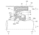
- FIG. 1 is a cross-sectional view taken along the axis x showing the configuration of the sealing device 10 according to the first embodiment of the present invention.
- FIG. 2 is a cross-sectional view in a cross section taken along the axis line x showing a use state of the sealing device 10 according to the first embodiment of the present invention.
- the sealing device 10 is used for a driving unit included in a robot (not shown) for various operations, particularly for a food factory.
- the sealing device 10 is attached to the rotation shaft of the joint drive device for rotating the arm, for example, in the housing (casing) of the robot.
- 103a shown by the alternate long and short dash line indicates the inner peripheral surface of the opening of the casing described later.
- the reference numeral a side of the sealing device 10 is the outer side
- the reference numeral b side of the sealing device 10 is the inner side
- the outside is the outside of the casing 103 where water, dust, etc. are present
- the inside is the inside of the casing 103.
- the direction away from the axis x is the outer peripheral side (arrow c direction)
- the direction toward the axis x is the inner peripheral side (arrow d). direction).
- the sealing device 10 includes a rotating shaft 102 that rotates about an axis x, and a casing 103 as an outer peripheral member that is arranged around the axis x on the outer peripheral side c of the rotating shaft 102. It is attached between the inner peripheral surface 103a of the opening and slidably contacts the outer peripheral surface 102g of the rotating shaft 102 to seal between the rotating shaft 102 and the casing 103.
- the sealing device 10 includes an annular reinforcing ring 20 around the axis x and an elastic body portion 30 attached to the reinforcing ring 20 and formed of an annular elastic body around the axis x.
- the elastic body portion 30 is a base 31.
- the tip portion whose diameter is reduced toward the inner peripheral side d has an annular tip surface 341 facing the outer side a in the axis x direction and around the axis x, and the tip surface 341 is a rotating shaft 102 in a used state. It has an angle of 90 degrees or more with respect to the outer peripheral surface 102 g.
- the configuration of the sealing device 10 will be specifically described.
- the reinforcing ring 20 is an annular metal member centered on or substantially centered on the axis x.
- the metal member used for the reinforcing ring 20 include stainless steel and SPCC (cold rolled steel).
- the reinforcing ring 20 is manufactured by pressing or forging such a metal member.
- the reinforcing ring 20 is, for example, a cylindrical portion 21 that is a cylindrical or substantially cylindrical portion that extends in the direction of the axis x, and a hollow disk-shaped portion that extends from the outer end of the cylindrical portion 21 toward the inner peripheral side. And a disc portion 24.
- the cylindrical portion 21 is formed so that the sealing device 10 can be fitted to the inner peripheral surface 103a of the through hole formed in the casing 103.
- the cylindrical portion 21 can be fitted in contact with the inner peripheral surface 103a of the opening of the casing 103, which is a through hole, via the elastic body portion 30.
- the cylindrical portion 21 may be shaped so as to form a pyramidal ring portion (not shown) in the intermediate portion of the cylindrical portion 21. Further, a part of the cylindrical portion 21 may be in direct contact with the inner peripheral surface 103a of the through hole so that it can be fitted.
- the sealing device 10 when the sealing device 10 is fitted to the inner peripheral surface 103a forming the opening 105 of the casing 103, the axis x of the sealing device 10 and the axis x of the rotating shaft 102 coincide with each other. It is fitted into the inner peripheral surface 103a of the through hole so as to be.
- An elastic body portion 30 is attached to the reinforcing ring 20 so as to wrap the reinforcing ring 20 from the outside (direction of arrow a) and the outer peripheral side (direction of arrow c). That is, the reinforcing ring 20 reinforces the elastic body portion 30.
- the elastic body portion 30 is attached to the reinforcing ring 20, and is integrally formed with the reinforcing ring 20 so as to cover the reinforcing ring 20.
- the elastic body of the elastic body portion 30 include various rubber materials. Examples of various rubber materials are synthetic rubbers such as nitrile rubber (NBR), hydrogenated nitrile rubber (H-NBR), acrylic rubber (ACM), and fluororubber (FKM).
- NBR nitrile rubber
- H-NBR hydrogenated nitrile rubber
- ACM acrylic rubber
- FKM fluororubber
- the elastic body portion 30 is molded by cross-linking (vulcanization) molding using a molding die.
- the reinforcing ring 20 is arranged in the molding die, the elastic body portion 30 is adhered to the reinforcing ring 20 by cross-linking adhesion, and the elastic body portion 30 and the reinforcing ring 20 are integrally molded. Will be done.
- the elastic body portion 30 is attached to the base portion 31 located in the vicinity of the inner peripheral side (arrow d direction) end of the disk portion 24 of the reinforcing ring 20 and the outer peripheral side (arrow c direction) of the cylindrical portion 21 of the reinforcing ring 20.
- a cover portion 33 which is a portion attached to the disc portion 24 of the reinforcing ring 20 from the outside (in the direction of arrow a) between the base portion 31 and the gasket portion 32, and the base portion 31.
- the base portion 31 supports the lip tip portion 36 of the lip portion 35 so as to be in sliding contact with the outer peripheral surface 102g of the rotating shaft 102 in a pressed state.
- the base portion 31 is located between the cover portion 33 and the dust strip 34 in the vicinity of the end portion on the inner peripheral d side of the disk portion 24.
- the disk portion 24 of the reinforcing ring 20 penetrates inside the base portion 31.
- the cover portion 33 is attached to the disk portion 24 from the outer side a, and is provided so as to face the outer side a in an annular shape around the axis x.
- the base 31 and the cover 33 are formed in a disk shape with a smooth surface. That is, the surfaces of the base portion 31 and the cover portion 33 facing the outside a are not provided with a concave shape (recess) such as an equal distribution groove formed when the elastic body portion 30 is formed.
- the equally distributed grooves 331 are provided on the inner side b that is not exposed on the outer side a.
- the gasket portion 32 is a portion of the elastic body portion 30 that covers the cylindrical portion 21 of the reinforcing ring 20 from the outer peripheral side c.
- the outer diameter of the gasket portion 32 is the same as or slightly larger than the inner diameter of the inner peripheral surface 103a. Therefore, when the sealing device 10 is fitted to the inner peripheral surface 103a of the opening of the casing 103, the gasket portion 32 is radially compressed between the cylindrical portion 21 of the reinforcing ring 20 and the casing 103, and the casing The space between the inner peripheral surface 103 a of the opening of 103 and the cylindrical portion 21 of the reinforcing ring 20 is sealed.
- the gasket portion 32 seals between the inner peripheral surface 103a of the opening of the casing 103 and the inner peripheral surface 103a of the opening of the casing 103, and the annular gap between the rotary shaft 102 is sealed by the sealing device 10. ..
- the gasket portion 32 is not limited to the one that covers the entire outer peripheral side c of the cylindrical portion 21 as shown in FIGS. 1 and 2.
- the gasket portion 32 may cover a part of the outer peripheral side c of the cylindrical portion 21.
- the dust lip 34 extends obliquely from the base 31 toward the outer peripheral surface 102g of the rotary shaft 102 located on the inner peripheral side d.
- the dust strip 34 is reduced in diameter from both sides of the outer a (outer peripheral surface 344) and the inner b (inner peripheral surface 343) toward the inner peripheral side d and the outer a in the axis x direction. It has a tapered cross section that extends to.
- the outer peripheral surface 344 of the dust lip 34 extends from a position flush with the cover portion 33 on the outer side a toward the inner peripheral side d in the axis x direction and to the outer side a.
- the inner peripheral surface 343 of the dust lip 34 extends from the position of the inner peripheral surface 37 on the inner side b toward the inner peripheral side d and the outer side a in the axis x direction.
- the dust lip 34 has an annular front end surface 341 that faces the outside a in the direction of the axis x and that surrounds the axis x.
- the dust strip 34 is 90 degrees with respect to the outer peripheral surface 102g of the rotating shaft 102 in a used state in which the tip surface 341 is in contact with the outer peripheral surface 102g of the rotating shaft 102 and the tip portion 342 and the inner peripheral surface 343. It is formed so as to have the above angle and face the outside a. As shown in FIG. 1, the tip surface 341 may have an angle of 90 degrees or more with respect to the axis x even when it is not fitted in the rotating shaft 102.
- the lip portion 35 of the elastic body portion 30 has a lip tip portion 36 in which an outer peripheral surface 102 g of the rotating shaft 102 is slidably formed at a tip extending from the base portion 31 along the axis x.
- the lip portion 35 has a conical cylindrical shape whose diameter decreases toward the inner peripheral side d as it goes inward (in the direction of arrow b) in the axis x direction. That is, in the cross section along the axis x (hereinafter, also simply referred to as “cross section”), the lip portion 35 is a lip of the lip tip portion 36 on the inner side (arrow b direction) and the inner circumferential side (arrow d direction) from the base 31.
- the lip portion 35 is provided with a concave portion on the outer peripheral side (in the direction of arrow c) facing the lip tip portion 36, and a garter spring 38, which is an annular elastic member serving as a tensioning force applying member, is attached to the concave portion. There is.
- the lip tip portion 36 is an annular portion having a wedge shape with a convex cross section toward the inner peripheral side (direction of arrow d).
- the lip tip portion 36 has a lip contact end 361 that slidably contacts the outer peripheral surface 102g of the rotating shaft 102.
- the garter spring 38 is, for example, a metal spring member, and has a predetermined shape in which the lip tip portion 36 is urged toward the inner peripheral side (arrow d direction) in the radial direction and the lip tip portion 36 is pressed against the outer peripheral surface 102 g of the rotating shaft 102. It gives a tense force of the size of. Note that the garter spring 38 is not limited to being made of metal, and may be made of various other materials such as resin, as long as the urging force is applied.
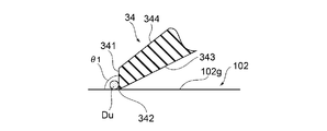
- FIG. 3 is a partially enlarged cross-sectional view for showing the dust strip 34 in the sealing device 10 according to the first embodiment of the present invention.
- the sealing device 10 is attached to the rotating shaft 102 of the housing (casing 103) of the joint driving device for rotating the driving unit of the robot, for example, the arm in the used state.
- the lip portion 35 of the elastic body portion 30 and the dust lip 34 contact the outer peripheral surface 102g of the rotating shaft 102 at the lip contact end 361 which is the tip of each and the inner peripheral surface 343 near the tip portion 342. doing.
- the lip portion 35 of the elastic body portion 30 and the dust strip 34 form a closed space between the inner peripheral surface 37 and the outer peripheral surface 102 g of the rotating shaft 102.
- the lip portion 35 and the dust lip 34 are deformed by the contact with the outer peripheral surface 102g of the rotating shaft 102.
- all of the lip portion 35 and the dust lip 34 may not be deformed, or one of them may not be deformed.
- the dust strip 34 has an inner circumference extending from the inner peripheral surface 37 of the elastic body portion 30 toward the inner peripheral side d and the outer peripheral a in the axis x direction in the used state.
- the tip portion 342 on the outer side a of the surface 343 and the inner peripheral surface 343 in the vicinity thereof are formed so as to come into contact with the outer peripheral surface 102g of the rotating shaft 102.
- the tip surface 341 of the dust strip 34 has an angle ⁇ 1 of 90 degrees or more with respect to the outer peripheral surface 102g of the rotating shaft 102 and faces the outside a.
- FIG. 4 is a cross-sectional view of a configuration of the sealing device 100 according to the comparative example, taken along the axis x.
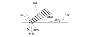
- FIG. 5 is a partially enlarged cross-sectional view for showing the dust strip 340 in the sealing device 100 according to the comparative example.
- the tip end surface 341a of the dust lip 340 is rotated with a predetermined angle ⁇ 2 of 90 degrees or less with respect to the axis x in the used state. It faces the outer peripheral surface 102g of the shaft 102.
- the surfaces of the base portion 310 and the cover portion 330 facing the outside a are not formed in a smooth disk shape.
- the sealing device 100 according to the comparative example is provided with a concave equidistant groove 331a formed when the elastic body portion 30 is formed on the surface of the cover portion 330 facing the outside a.
- the surface of the outer side a of the base portion 310 is formed in a concave shape from the surface of the outer side a of the cover portion 330 toward the inner side b.
- the dust lip 340 extends obliquely from the base portion 310 thus formed toward the outer peripheral surface 102g of the rotary shaft 102 located on the inner peripheral side d.
- the tip end surface 341a of the dust lip 340 does not protrude outside the surface a of the cover portion 330 in the axial direction x.
- the sealing device 100 according to the comparative example configured as described above, dust is accumulated in the inner circumferential side d of the tip end surface 341a of the dust lip 340, the equally distributed grooves 331a of the concave cover portion 330, and the like. It's easy to do. Further, in the sealing device 100 according to the comparative example, when the dust Du adheres to the outer peripheral surface 102g of the rotating shaft 102 in the used state as shown in FIG. 5, the dust Du adheres to the tip surface 341a of the dust strip 340. It may get into the inner peripheral side d. In this case, it is difficult to easily remove the dust Du that has entered the inner peripheral side d of the tip surface 341a of the dust strip 340 by a simple operation such as high-pressure cleaning.
- the tip surface 341 has an angle ⁇ 1 of 90 degrees or more with respect to the outer peripheral surface 102 g of the rotating shaft 102 in the used state as described above. It faces the outside a. Therefore, according to the sealing device 10, the dust Du is easily exposed on the outer peripheral side c of the tip surface 341 of the dust strip or the outer peripheral surface 102g of the rotating shaft 102, and is less likely to enter the inner peripheral side d. Therefore, according to the sealing device 10, the dust Du can be easily removed by a simple operation.
- the base portion 31 is formed in a disk shape with a smooth surface together with the cover portion 33, and the equal distribution grooves 331 are provided on the inner side b, so that the portion exposed on the outer side a has a concave shape. Is not provided. Therefore, according to the sealing device 10, the dust Du can be easily removed by a simple operation.
- the sealing device 10 it is possible to easily remove the attached matter such as the dust Du by a simple operation such as high pressure cleaning.
- FIG. 6 is a cross-sectional view in a cross-section taken along the axis x showing the configuration of the sealing device 10B according to the second embodiment of the present invention.
- FIG. 7 is a cross-sectional view in a cross-section taken along the axis line x showing a usage state of the sealing device 10B according to the second embodiment of the present invention.
- the sealing device 10B according to the second embodiment is different from the sealing device 10 described above in the shapes of the reinforcing ring 20 and the lip portion 35b.
- the reinforcing ring 20 is a pyramidal ring that extends diagonally inward from the end on the inner peripheral side of the disk portion 24 to the tip portion of the inner peripheral side d of the disk portion 24.
- the portion 22 is formed.
- the lip portion 35b of the sealing device 10B extends from the base portion 31 inward (in the direction of arrow b) along the axis x, and the lip tip portion 36b protruding inward (direction of arrow d) is outward (direction of arrow a).
- the lip portion 35b of the sealing device 10B is not provided with a recess on the outer peripheral side (direction of arrow c) facing the lip tip portion 36b, so that a garter spring is also attached. Not.
- the tip end surface 341 of the dust lip 34 is The outer peripheral surface 102g of the rotating shaft 102 faces the outer side a at an angle of 90 degrees or more. Therefore, according to the sealing device 10B, the dust Du does not enter the inner peripheral side d of the tip surface 341 of the dust lip.
- the base portion 31 is formed in a disk shape with a smooth surface together with the cover portion 33, and the equal distribution grooves 331 are provided on the inner side b, so that the portion exposed on the outer side a has a concave shape. Not provided. Therefore, according to the sealing device 10B, the dust Du does not enter the recess which is difficult to remove by a simple operation.
- dust Du can be easily removed by a simple operation such as high pressure washing.
- the present invention is not limited to the sealing devices 10 and 10B according to the above embodiments, and includes all aspects included in the concept and claims of the present invention. .. Further, the respective configurations may be appropriately and selectively combined so as to achieve at least a part of the problems and effects described above. For example, the shape, material, arrangement, size, etc. of each constituent element in the above-described embodiment can be appropriately changed depending on the specific usage mode of the present invention.
- the sealing devices 10 and 10B have been described as being attached to the rotating shaft 102 of the joint driving device of the robot, but the present invention is not limited thereto. That is, the sealing devices 10 and 10B may be used as a sealing device between a driving unit other than the joint driving device, for example, a swivel shaft of a swivel portion that swivels an arm in a robot and a casing. Further, the sealing devices 10 and 10B may be used as a sealing device between a driving unit other than the joint driving device, for example, a rotating shaft of a rotating portion that rotates a wrist portion in a robot and a casing.
- sealing devices 10 and 10B are other devices as long as they seal between the rotary shaft 102 and the outer peripheral side member arranged on the outer peripheral side c thereof, for example, the rotary shaft of the speed reducer and the outer peripheral side member (casing). ) Can also be used as a sealing device (oil seal).
Landscapes
- Engineering & Computer Science (AREA)
- General Engineering & Computer Science (AREA)
- Mechanical Engineering (AREA)
- Sealing With Elastic Sealing Lips (AREA)
- Sealing Devices (AREA)
Abstract
付着物を容易に除去することができる。 密封装置(10)は、回転軸と、外周側部材との間に取り付けられ、回転軸の外周面に摺動可能に接触して、回転軸と外周側部材との間を密封する。密封装置(10)は、軸線(x)周りに環状の補強環(20)と、補強環(20)に取り付けられ、軸線(x)周りに環状の弾性体からなる弾性体部(30)と、を備え、弾性体部(30)は、基部(31)と、少なくとも1つの軸線(x)周りに環状のダストリップ(34)と、を有し、ダストリップ(34)は、基部(31)から軸線(x)方向において内周側(d)、且つ、外側(a)に向かって延びていて軸線(x)方向において内周側(d)に向かうに連れて縮径する先端部分に軸線(x)方向において外側(a)に面し軸線(x)周りに環状の先端面(341)を有し、先端面(341)は、使用状態において回転軸の外周面に対して90度以上の角度を有している。
Description
本発明は、密封装置に関する。
ロボットは、人間に代わって様々な作業を行うために用いられている。ロボットは、作業を行うためのアームを回動させるために、例えばモータと回転軸とを備える関節駆動装置を備えている。
以上のようなロボットの関節駆動装置において、回転軸とケースとの間に潤滑剤を封止するための密封装置(オイルシール)を備えるものが提案されている(例えば、特許文献1を参照)。
また、ロボット・減速機用の密封装置において、密封対象をシールする主シールと、主シールの密封対象側に配置されて異物を除去する補助シールとを有するものが提案されている(例えば、特許文献2を参照)。
ところで、ロボットは、近年、食品や飲料品などを製造する工場(以下「食品工場」という。)においても、作業の省力化や自動化の観点から用いられつつある。食品工場用のロボットは、製造される食品の衛生面を考慮して、密封装置が取り付けられる関節駆動装置を含めてちりやほこりなどのダストを容易に除去可能であることが求められている。また、食品工場用のロボットは、例えば高圧の水を用いて洗浄するなどの簡易な作業により、ダストのような付着物を除去できることも求められている。
しかしながら、上述した特許文献1及び特許文献2を含め、ロボットの回転軸に用いられる従来の密封装置においては、外側(大気側)に露出している部分の例えばダストリップと回転軸との接触部分の周囲やその他の凹部にダストが堆積しやすかった。また、従来の密封装置においては、このような接触部分の周囲や凹部に堆積したダストのような付着物を除去しにくかった。
本発明は、上述の課題に鑑みてなされたものであり、その目的は、付着物を容易に除去することができる密封装置を提供することである。
上記目的を達成するために、本発明に係る密封装置は、軸線周りに回転する回転軸と、回転軸よりも外周側において軸線周りに配置された外周側部材との間に取り付けられ、前記回転軸の外周面に摺動可能に接触して、前記回転軸と前記外周側部材との間を密封する密封装置であって、前記軸線周りに環状の補強環と、前記補強環に取り付けられ、前記軸線周りに環状の弾性体からなる弾性体部と、を備え、前記弾性体部は、基部と、少なくとも1つの前記軸線周りに環状のダストリップと、を有し、前記ダストリップは、前記基部から前記軸線方向において内周側、且つ、外側に向かって延びていて前記軸線方向において内周側に向かうに連れて縮径する先端部分に前記軸線方向において外側に面し前記軸線周りに環状の先端面を有し、前記先端面は、使用状態において前記回転軸の外周面に対して90度以上の角度を有している。
本発明の一態様に係る密封装置において、前記補強環は、軸線方向に延びる円筒状の円筒部と、前記円筒部の外側の端部から内周側に向かって延びる中空円盤状の円盤部と、を有し、前記弾性体部は、外側から前記円盤部に取り付けられていて前記軸線周りに環状で外側に面し、且つ、平滑な円盤状に形成されているカバー部を有している。
本発明の一態様に係る密封装置において、前記基部は、前記円盤部の内周側の端部近傍において前記カバー部と前記ダストリップとの間に位置し、前記ダストリップは、前記カバー部と面一の位置から前記軸線方向において内周側、且つ、外側に向かって延びている。
本発明の一態様に係る密封装置において、当該密封装置は、ロボットにおける駆動部が備える回転軸とケーシングとの間の密封装置として用いられる。
本発明に係る密封装置によれば、付着物を容易に除去することができる。
<第1の実施の形態>
以下、本発明の第1の実施の形態について図面を参照しながら説明する。
以下、本発明の第1の実施の形態について図面を参照しながら説明する。
図1は、本発明の第1の実施の形態に係る密封装置10の構成を示す軸線xに沿う断面における断面図である。また、図2は、本発明の第1の実施の形態に係る密封装置10の使用状態を示す軸線xに沿う断面における断面図である。
第1の実施の形態に係る密封装置10は、特に食品工場用などの各種作業用の不図示のロボットが備える駆動部に用いられる。密封装置10は、具体的には、駆動部の一例として、例えばロボットの筐体(ケーシング)において、アームを回動させるための関節駆動装置の回転軸に取り付けられている。図1において、二点鎖線で示す103aは、後述するケーシングの開口部の内周面を示している。
以下、説明の便宜上、図面において密封装置10よりも符号a側を外側、密封装置10よりも符号b側を内側とする。ここで、外側とはケーシング103の外部であって水や埃等が存在する側であり、内側とはケーシング103の内側である。また、軸線xに垂直な方向(以下、「径方向」ともいう。)において、軸線xから遠ざかる方向を外周側とし(矢印c方向)、軸線xに向かう方向を内周側とする(矢印d方向)。
図1及び図2に示すように、密封装置10は、軸線x周りに回転する回転軸102と、回転軸102よりも外周側cにおいて軸線x周りに配置された外周側部材としてのケーシング103の開口部の内周面103aとの間に取り付けられ、回転軸102の外周面102gに摺動可能に接触して、回転軸102とケーシング103との間を密封する。密封装置10は、軸線x周りに環状の補強環20と、補強環20に取り付けられ、軸線x周りに環状の弾性体からなる弾性体部30と、を備え、弾性体部30は、基部31と、少なくとも1つの軸線x周りに環状のダストリップ34と、を有し、ダストリップ34は、基部31から軸線x方向において内周側d、且つ、外側aに向かって延びていて軸線x方向において内周側dに向かうに連れて縮径する先端部分に軸線x方向において外側aに面し軸線x周りに環状の先端面341を有し、先端面341は、使用状態において回転軸102の外周面102gに対して90度以上の角度を有している。以下、密封装置10の構成を具体的に説明する。
補強環20は、図1に示すように、軸線xを中心又は略中心とする環状の金属製の部材である。補強環20に用いられる金属製の部材として、例えば、ステンレス鋼やSPCC(冷間圧延鋼)が挙げられる。補強環20は、このような金属製の部材を例えばプレス加工や鍛造することによって製造される。補強環20は、例えば、軸線x方向に延びる円筒状又は略円筒状の部分である円筒部21と、円筒部21の外側の端部から内周側に向かって延びる中空円盤状の部分である円盤部24と、を有している。円筒部21は、後述するように、ケーシング103に形成された貫通孔の内周面103aに密封装置10が嵌合可能となるように形成されている。円筒部21は、弾性体部30の部分を介して貫通孔であるケーシング103の開口部の内周面103aに接触して嵌合可能となっている。円筒部21は、円筒部21の中間部分に不図示の錐環部を形成するような形状となっていてもよい。また、円筒部21は、一部分が直接貫通孔の内周面103aに接触して嵌合可能となっていてもよい。円筒部21は、密封装置10がケーシング103の開口部105を形成している内周面103aに嵌着された際に、密封装置10の軸線xと回転軸102の軸線xとの一致が図られるように貫通孔の内周面103aに嵌め込まれる。
補強環20には、補強環20を外側(矢印a方向)かつ外周側(矢印c方向)から包み込むように弾性体部30が取り付けられている。つまり、補強環20は、弾性体部30を補強している。
弾性体部30は、上述のように、補強環20に取り付けられており、補強環20を覆うように補強環20と一体的に形成されている。弾性体部30の弾性体としては、例えば、各種ゴム材がある。各種ゴム材としては、例えば、ニトリルゴム(NBR)、水素添加ニトリルゴム(H-NBR)、アクリルゴム(ACM)、フッ素ゴム(FKM)等の合成ゴムである。弾性体部30は、成形型を用いて架橋(加硫)成形によって成形される。この架橋成形の際に、補強環20は成形型の中に配置されており、弾性体部30が架橋接着により補強環20に接着され、弾性体部30と補強環20とが一体的に成形される。
弾性体部30は、補強環20における円盤部24の内周側(矢印d方向)の端部近傍に位置する基部31と、補強環20の円筒部21に外周側(矢印c方向)から取り付けられている部分であるガスケット部32と、基部31とガスケット部32との間において外側(矢印a方向)から補強環20の円盤部24に取り付けられている部分であるカバー部33と、基部31から軸線x方向において内周側(矢印d方向)、且つ、外側(矢印a方向)に向かって延びていて軸線x方向において内周側dに向かうに連れて縮径する先端部分を有するダストリップ34と、基部31から内側(矢印b方向)へ軸線xに沿って延びるとともに、内周側(矢印d方向)へ突出したリップ先端部分36が形成されたリップ部35と、弾性体部30の内周側に面する環状の面である内周面37とを有している。
基部31は、リップ部35のリップ先端部分36を回転軸102の外周面102gに押し付けた状態で摺接させるように支持する。基部31は、円盤部24の内周d側の端部近傍においてカバー部33とダストリップ34との間に位置する。補強環20の円盤部24は、基部31の内部に入り込んでいる。カバー部33は、上述のように外側aから円盤部24に取り付けられていて、軸線x周りに環状で外側aに面するように設けられている。
基部31は、カバー部33とともに表面が平滑な円盤状に形成されている。つまり、基部31及びカバー部33の外側aを向く面は、例えば弾性体部30を成形する際に形成される等配溝などの凹形状(凹部)が設けられていない。密封装置10において、等配溝331は、外側aに露出しない内側bに設けられている。
ガスケット部32は、弾性体部30において、補強環20の円筒部21を外周側cから覆っている部分である。ガスケット部32は、その外径が、内周面103aの内径と同じか、それよりも僅かに大きくなっている。このため、密封装置10がケーシング103の開口部の内周面103aに嵌着された場合、ガスケット部32は、補強環20の円筒部21とケーシング103との間で径方向に圧縮され、ケーシング103の開口部の内周面103aと補強環20の円筒部21との間を密封する。
ガスケット部32がケーシング103の開口部の内周面103aとの間を密封することにより、ケーシング103の開口部の内周面103aと回転軸102との環状の隙間が密封装置10によって密封される。なお、ガスケット部32は、図1及び図2に示すように円筒部21の外周側cの全体を覆っているものには限定されない。例えば、ガスケット部32は、円筒部21の外周側cの一部を覆うものであってもよい。
ダストリップ34は、基部31から内周側dに位置する回転軸102の外周面102gに向かって斜めに延びている。具体的には、ダストリップ34は、外側a(外周面344)及び内側b(内周面343)の両側から、軸線x方向において内周側d、且つ、外側aに向かって縮径するように延びているテーパー形状の断面を有している。ダストリップ34の外周面344は、外側aにおけるカバー部33と面一の位置から軸線x方向において内周側d、且つ、外側aに向かって延びている。また、ダストリップ34の内周面343は、内側bにおける内周面37の位置から軸線x方向において内周側d、且つ、外側aに向かって延びている。ダストリップ34は、軸線x方向において外側aに面し軸線x周りに環状の先端面341を有する。
ダストリップ34は、図2に示すように先端面341が、回転軸102の外周面102gに先端部342及び内周面343が接する使用状態において、回転軸102の外周面102gに対して90度以上の角度を有して外側aを向くように形成されている。なお、先端面341は、図1に示すように、回転軸102に嵌め込まれていない状態においても、軸線xに対して90度以上の角度を有していてもよい。
弾性体部30のリップ部35は、基部31から軸線xに沿って延びる先端に、回転軸102の外周面102gが摺動可能に形成されたリップ先端部分36を有している。リップ部35は、軸線x方向において内側(矢印b方向)に向かうに連れて内周側dに縮径する円錐筒状の形状を有している。つまり、リップ部35は、軸線xに沿う断面(以下、単に「断面」ともいう。)において、基部31から内側(矢印b方向)及び内周側(矢印d方向)のリップ先端部分36のリップ接触端361に向けて、軸線xに対して斜めに延びている。リップ部35は、リップ先端部分36と背向する外周側(矢印c方向)に凹部が設けられており、この凹部に緊迫力付与部材としての環状の弾性部材であるガータスプリング38が装着されている。
リップ先端部分36は、内周側(矢印d方向)へ向かって断面が凸の楔形状を有する環状の部分である。リップ先端部分36は、回転軸102の外周面102gと摺動自在に接触するリップ接触端361を有している。
ガータスプリング38は、例えば金属製のバネ部材であり、リップ先端部分36を径方向において内周側(矢印d方向)へ付勢し、リップ先端部分36を回転軸102の外周面102gに押し付ける所定の大きさの緊迫力を付与するものである。なお、ガータスプリング38は、緊迫力を付与するものであれば、金属製に限らず、樹脂製等のその他種々の材料によるものであってもよい。
次に、上述の構成を備える密封装置10の作用について説明する。図3は、本発明の第1の実施の形態に係る密封装置10におけるダストリップ34を示すための部分拡大断面図である。
図2に示すように、密封装置10は、使用状態において、ロボットの駆動部、例えばアームを回動させるための関節駆動装置の筐体(ケーシング103)の回転軸102に取り付けられている。
使用状態において、弾性体部30のリップ部35、及びダストリップ34は、夫々の先端であるリップ接触端361、及び先端部342近傍の内周面343において、回転軸102の外周面102gに接触している。使用状態において、弾性体部30のリップ部35、及びダストリップ34は、内周面37と回転軸102の外周面102gとの間に閉じられた空間を形成している。回転軸102の外周面102gとの接触により、リップ部35、及びダストリップ34は変形している。なお、使用状態において、リップ部35、及びダストリップ34の全てが変形しないようになっていてもよく、いずれかが変形しないようになっていてもよい。
ダストリップ34は、図2及び図3に示すように、使用状態において、弾性体部30の内周面37から軸線x方向において内周側d、且つ、外側aに向かって延びている内周面343の外側aの先端部342及びその近傍の内周面343が回転軸102の外周面102gに接触するように形成されている。このような状態において、ダストリップ34は、先端面341が、回転軸102の外周面102gに対して90度以上の角度θ1を有して外側aを向いている。
図4は、比較例に係る密封装置100の構成を示す軸線xに沿う断面における断面図である。また、図5は、比較例に係る密封装置100におけるダストリップ340を示すための部分拡大断面図である。図4及び図5に示すように、比較例に係る密封装置100は、ダストリップ340の先端面341aが、使用状態において、軸線xに対して90度以下の所定の角度θ2を有して回転軸102の外周面102gに面している。
比較例に係る密封装置100は、基部310及びカバー部330の外側aを向く面が、平滑な円盤状に形成されていない。具体的には、比較例に係る密封装置100は、カバー部330の外側aを向く面に弾性体部30を成形する際に形成される凹形状の等配溝331aが設けられている。また、比較例に係る密封装置100は、基部310の外側aの面がカバー部330の外側aの面から内側bの方向へ凹形状に形成されている。ダストリップ340は、このように形成されている基部310から内周側dに位置する回転軸102の外周面102gに向かって斜めに延びている。換言すれば、ダストリップ340の先端面341aは、軸線x方向においてカバー部330の表面よりも外側aには突出していない。
以上のように構成されている比較例に係る密封装置100では、ダストリップ340の先端面341aの内周側dや凹形状に形成されているカバー部330の等配溝331aなどにダストが堆積しやすい。また、比較例に係る密封装置100は、図5に示すように使用状態において回転軸102の外周面102gの上にダストDuが付着した場合に、ダストDuが、ダストリップ340の先端面341aの内周側dに入り込んでしまうことがある。この場合において、ダストリップ340の先端面341aの内周側dに入り込んでしまったダストDuは、例えば高圧洗浄などの簡易な作業により容易に除去することが難しい。
一方、本実施の形態に係る密封装置10のダストリップ34は、上述のように使用状態において、先端面341が、回転軸102の外周面102gに対して90度以上の角度θ1を有して外側aを向いている。このため、密封装置10によれば、ダストDuがダストリップの先端面341の外周側cまたは回転軸102の外周面102gの上に露出しやすく、内周側dに入り込みにくい。このため、密封装置10によれば、ダストDuを簡易な作業により除去しやすい。
また、密封装置10において、基部31は、カバー部33とともに表面が平滑な円盤状に形成されていて、等配溝331が内側bに設けられているため、外側aに露出する部分に凹形状が設けられていない。このため、密封装置10によれば、ダストDuを簡易な作業により除去しやすい。
以上説明したように、密封装置10によれば、高圧洗浄などの簡易な作業によりダストDuのような付着物を容易に除去することができる。
<第2の実施の形態>
以下、本発明の第2の実施の形態について図面を参照しながら説明する。以下、上述の第1の実施の形態に係る密封装置10と同一の又は類似する機能を有する構成に対しては同一の符号を付してその説明を省略し、異なる構成についてのみ説明する。
以下、本発明の第2の実施の形態について図面を参照しながら説明する。以下、上述の第1の実施の形態に係る密封装置10と同一の又は類似する機能を有する構成に対しては同一の符号を付してその説明を省略し、異なる構成についてのみ説明する。
図6は、本発明の第2の実施の形態に係る密封装置10Bの構成を示す軸線xに沿う断面における断面図である。また、図7は、本発明の第2の実施の形態に係る密封装置10Bの使用状態を示す軸線xに沿う断面における断面図である。
図6に示すように、第2の実施の形態に係る密封装置10Bは、補強環20及びリップ部35bの形状が先に説明した密封装置10と異なる。具体的には、補強環20は、円盤部24の内周側dの先端部分に、円盤部24の内周側の端部から内側に向かって内周側に斜めに延びる部分である錐環部22が形成されている。また、密封装置10Bのリップ部35bは、基部31から内側(矢印b方向)へ軸線xに沿って延びるとともに内周側(矢印d方向)へ突出したリップ先端部分36bが、外側(矢印a方向)に向かって延びていて軸線x方向において内周側dのリップ接触端361bに向かうに連れて縮径する。また、密封装置10Bのリップ部35bは、密封装置10のリップ部35と異なり、リップ先端部分36bと背向する外周側(矢印c方向)に凹部が設けられていないため、ガータスプリングも装着されていない。
以上のように構成されている、本実施の形態に係る密封装置10Bによれば、上述の密封装置10と同様に、図7に示すように使用状態において、ダストリップ34の先端面341が、回転軸102の外周面102gに対して90度以上の角度を有して外側aを向いている。このため、密封装置10Bによれば、ダストDuがダストリップの先端面341の内周側dに入り込むことがない。
また、密封装置10Bにおいて、基部31は、カバー部33とともに表面が平滑な円盤状に形成されていて等配溝331が内側bに設けられているため、外側aに露出する部分に凹形状が設けられていない。このため、密封装置10Bによれば、ダストDuが簡易な作業により除去しにくい凹部に入り込むことがない。
以上説明したように、密封装置10Bによれば、高圧洗浄などの簡易な作業によりダストDuを容易に除去することができる。
<他の実施の形態>
以上、本発明の実施の形態について説明したが、本発明は上記実施の形態に係る密封装置10,10Bに限定されるものではなく、本発明の概念及び請求の範囲に含まれるあらゆる態様を含む。また、上述した課題及び効果の少なくとも一部を奏するように、各構成を適宜選択的に組み合わせてもよい。例えば、上記実施の形態における、各構成要素の形状、材料、配置、サイズ等は、本発明の具体的使用態様によって適宜変更され得る。
以上、本発明の実施の形態について説明したが、本発明は上記実施の形態に係る密封装置10,10Bに限定されるものではなく、本発明の概念及び請求の範囲に含まれるあらゆる態様を含む。また、上述した課題及び効果の少なくとも一部を奏するように、各構成を適宜選択的に組み合わせてもよい。例えば、上記実施の形態における、各構成要素の形状、材料、配置、サイズ等は、本発明の具体的使用態様によって適宜変更され得る。
例えば、上記実施の形態において、密封装置10,10Bは、ロボットの関節駆動装置の回転軸102に取り付けられているものとして説明したが、これに限定されない。すなわち、密封装置10,10Bは、関節駆動装置以外の駆動部、例えばロボットにおいてアームを旋回させる旋回部の旋回用シャフトとケーシングとの間の密封装置として用いてもよい。また、密封装置10,10Bは、関節駆動装置以外の駆動部、例えばロボットにおいて手首部分を回転させる回転部の回転軸とケーシングとの間の密封装置として用いてもよい。さらに、密封装置10,10Bは、回転軸102とその外周側cに配置された外周側部材との間を密封するものであれば他の装置、例えば減速機の回転軸と外周側部材(ケーシング)との間の密封装置(オイルシール)にも用いることができる。
10…密封装置、20…補強環、21…円筒部、22…錐環部、24…円盤部、30…弾性体部、31…基部、32…ガスケット部、33…カバー部、34…ダストリップ、35…リップ部、36…リップ先端部分、37…内周面、38…ガータスプリング(緊迫力付与部材)、102…回転軸(軸)、102g…外周面、103…ケーシング(外周側部材)、103a…内周面、105…開口部、310…基部、341…先端面、342…先端部、343…内周面、344…外周面、361…リップ接触端、x…軸線。
Claims (4)
- 軸線周りに回転する回転軸と、回転軸よりも外周側において軸線周りに配置された外周側部材との間に取り付けられ、前記回転軸の外周面に摺動可能に接触して、前記回転軸と前記外周側部材との間を密封する密封装置であって、
前記軸線周りに環状の補強環と、
前記補強環に取り付けられ、前記軸線周りに環状の弾性体からなる弾性体部と、を備え、
前記弾性体部は、基部と、前記基部から前記軸線に沿って延びるリップ部と、少なくとも1つの前記軸線周りに環状のダストリップと、を有し、
前記リップ部は、前記基部から前記軸線に沿って延びる先端に、前記回転軸の外周面が摺動可能に形成されたリップ先端部分を有し、
前記ダストリップは、前記基部から前記軸線方向において内周側、且つ、外側に向かって延びていて前記軸線方向において内周側に向かうに連れて縮径する先端部分に前記軸線方向において外側に面し前記軸線周りに環状の先端面を有し、
前記先端面は、使用状態において前記回転軸の外周面に対して90度以上の角度を有している密封装置。 - 前記補強環は、軸線方向に延びる円筒状の円筒部と、前記円筒部の外側の端部から内周側に向かって延びる中空円盤状の円盤部と、を有し、
前記弾性体部は、外側から前記円盤部に取り付けられていて前記軸線周りに環状で外側に面し、且つ、平滑な円盤状に形成されているカバー部を有している、
請求項1に記載の密封装置。 - 前記基部は、前記円盤部の内周側の端部近傍において前記カバー部と前記ダストリップとの間に位置し、
前記ダストリップは、前記カバー部と面一の位置から前記軸線方向において内周側、且つ、外側に向かって延びている、
請求項2に記載の密封装置。 - 当該密封装置は、ロボットにおける駆動部が備える回転軸とケーシングとの間の密封装置として用いられる、
請求項1乃至3のいずれかに記載の密封装置。
Priority Applications (2)
| Application Number | Priority Date | Filing Date | Title |
|---|---|---|---|
| JP2020539306A JP7097451B2 (ja) | 2019-03-05 | 2020-02-27 | 密封装置 |
| CN202080001185.1A CN111902662B (zh) | 2019-03-05 | 2020-02-27 | 密封装置 |
Applications Claiming Priority (2)
| Application Number | Priority Date | Filing Date | Title |
|---|---|---|---|
| JP2019039224 | 2019-03-05 | ||
| JP2019-039224 | 2019-03-05 |
Publications (1)
| Publication Number | Publication Date |
|---|---|
| WO2020179622A1 true WO2020179622A1 (ja) | 2020-09-10 |
Family
ID=72338639
Family Applications (1)
| Application Number | Title | Priority Date | Filing Date |
|---|---|---|---|
| PCT/JP2020/008061 Ceased WO2020179622A1 (ja) | 2019-03-05 | 2020-02-27 | 密封装置 |
Country Status (3)
| Country | Link |
|---|---|
| JP (1) | JP7097451B2 (ja) |
| CN (1) | CN111902662B (ja) |
| WO (1) | WO2020179622A1 (ja) |
Citations (2)
| Publication number | Priority date | Publication date | Assignee | Title |
|---|---|---|---|---|
| JPH0542833U (ja) * | 1991-11-08 | 1993-06-11 | エヌオーケー株式会社 | オイルシール |
| JP2017067268A (ja) * | 2015-10-02 | 2017-04-06 | Nok株式会社 | 密封装置 |
Family Cites Families (1)
| Publication number | Priority date | Publication date | Assignee | Title |
|---|---|---|---|---|
| EP3351833B1 (en) * | 2015-09-25 | 2020-07-08 | NOK Corporation | Sealing device for differential mechanism |
-
2020
- 2020-02-27 CN CN202080001185.1A patent/CN111902662B/zh active Active
- 2020-02-27 WO PCT/JP2020/008061 patent/WO2020179622A1/ja not_active Ceased
- 2020-02-27 JP JP2020539306A patent/JP7097451B2/ja active Active
Patent Citations (2)
| Publication number | Priority date | Publication date | Assignee | Title |
|---|---|---|---|---|
| JPH0542833U (ja) * | 1991-11-08 | 1993-06-11 | エヌオーケー株式会社 | オイルシール |
| JP2017067268A (ja) * | 2015-10-02 | 2017-04-06 | Nok株式会社 | 密封装置 |
Also Published As
| Publication number | Publication date |
|---|---|
| CN111902662B (zh) | 2022-12-20 |
| JP7097451B2 (ja) | 2022-07-07 |
| JPWO2020179622A1 (ja) | 2021-03-11 |
| CN111902662A (zh) | 2020-11-06 |
Similar Documents
| Publication | Publication Date | Title |
|---|---|---|
| WO2021182057A1 (ja) | 密封装置および歯車減速機 | |
| JP6010875B1 (ja) | 密封装置 | |
| JP7042909B2 (ja) | 密封装置及び密封装置による密封方法 | |
| WO2021039839A1 (ja) | 密封装置 | |
| JP6590293B2 (ja) | 密封装置 | |
| JP6399471B2 (ja) | 密封装置及びその製造方法 | |
| JP7097451B2 (ja) | 密封装置 | |
| JP6566384B2 (ja) | 密封装置 | |
| JP3407436B2 (ja) | 密封装置 | |
| CN212251132U (zh) | 密封装置 | |
| JP2016196928A (ja) | 密封装置 | |
| WO2018117100A1 (ja) | 密封装置 | |
| JP2013167317A (ja) | フローティングシール | |
| CN111492161B (zh) | 密封装置 | |
| JP2020186768A (ja) | 密封装置 | |
| JP4415600B2 (ja) | オイルシールによる密封構造 | |
| WO2020230506A1 (ja) | 密封装置 | |
| JP6868386B2 (ja) | 密封装置 | |
| JP6628207B2 (ja) | 密封装置 | |
| JP5233805B2 (ja) | 密封装置、及びこれを用いた転がり軸受装置 | |
| JP7011716B2 (ja) | 密封装置 | |
| JP2021188623A (ja) | 密封装置 | |
| JPH11280916A (ja) | 回転軸シール | |
| JP6516199B2 (ja) | 密封装置 | |
| JP6368152B2 (ja) | 密封装置 |
Legal Events
| Date | Code | Title | Description |
|---|---|---|---|
| ENP | Entry into the national phase |
Ref document number: 2020539306 Country of ref document: JP Kind code of ref document: A |
|
| 121 | Ep: the epo has been informed by wipo that ep was designated in this application |
Ref document number: 20765481 Country of ref document: EP Kind code of ref document: A1 |
|
| NENP | Non-entry into the national phase |
Ref country code: DE |
|
| 122 | Ep: pct application non-entry in european phase |
Ref document number: 20765481 Country of ref document: EP Kind code of ref document: A1 |