WO2020179100A1 - 粉体のコーティング装置およびコーティング方法、粉体分散装置ならびに粉体分散方法 - Google Patents
粉体のコーティング装置およびコーティング方法、粉体分散装置ならびに粉体分散方法 Download PDFInfo
- Publication number
- WO2020179100A1 WO2020179100A1 PCT/JP2019/030268 JP2019030268W WO2020179100A1 WO 2020179100 A1 WO2020179100 A1 WO 2020179100A1 JP 2019030268 W JP2019030268 W JP 2019030268W WO 2020179100 A1 WO2020179100 A1 WO 2020179100A1
- Authority
- WO
- WIPO (PCT)
- Prior art keywords
- powder
- slurry
- flow
- coating
- air flow
- Prior art date
- Legal status (The legal status is an assumption and is not a legal conclusion. Google has not performed a legal analysis and makes no representation as to the accuracy of the status listed.)
- Ceased
Links
Images






Classifications
-
- H—ELECTRICITY
- H01—ELECTRIC ELEMENTS
- H01M—PROCESSES OR MEANS, e.g. BATTERIES, FOR THE DIRECT CONVERSION OF CHEMICAL ENERGY INTO ELECTRICAL ENERGY
- H01M4/00—Electrodes
- H01M4/02—Electrodes composed of, or comprising, active material
- H01M4/13—Electrodes for accumulators with non-aqueous electrolyte, e.g. for lithium-accumulators; Processes of manufacture thereof
- H01M4/139—Processes of manufacture
-
- B—PERFORMING OPERATIONS; TRANSPORTING
- B01—PHYSICAL OR CHEMICAL PROCESSES OR APPARATUS IN GENERAL
- B01J—CHEMICAL OR PHYSICAL PROCESSES, e.g. CATALYSIS OR COLLOID CHEMISTRY; THEIR RELEVANT APPARATUS
- B01J2/00—Processes or devices for granulating materials, e.g. fertilisers in general; Rendering particulate materials free flowing in general, e.g. making them hydrophobic
- B01J2/006—Coating of the granules without description of the process or the device by which the granules are obtained
-
- B—PERFORMING OPERATIONS; TRANSPORTING
- B01—PHYSICAL OR CHEMICAL PROCESSES OR APPARATUS IN GENERAL
- B01J—CHEMICAL OR PHYSICAL PROCESSES, e.g. CATALYSIS OR COLLOID CHEMISTRY; THEIR RELEVANT APPARATUS
- B01J2/00—Processes or devices for granulating materials, e.g. fertilisers in general; Rendering particulate materials free flowing in general, e.g. making them hydrophobic
- B01J2/003—Processes or devices for granulating materials, e.g. fertilisers in general; Rendering particulate materials free flowing in general, e.g. making them hydrophobic followed by coating of the granules
-
- B—PERFORMING OPERATIONS; TRANSPORTING
- B01—PHYSICAL OR CHEMICAL PROCESSES OR APPARATUS IN GENERAL
- B01J—CHEMICAL OR PHYSICAL PROCESSES, e.g. CATALYSIS OR COLLOID CHEMISTRY; THEIR RELEVANT APPARATUS
- B01J2/00—Processes or devices for granulating materials, e.g. fertilisers in general; Rendering particulate materials free flowing in general, e.g. making them hydrophobic
- B01J2/02—Processes or devices for granulating materials, e.g. fertilisers in general; Rendering particulate materials free flowing in general, e.g. making them hydrophobic by dividing the liquid material into drops, e.g. by spraying, and solidifying the drops
- B01J2/04—Processes or devices for granulating materials, e.g. fertilisers in general; Rendering particulate materials free flowing in general, e.g. making them hydrophobic by dividing the liquid material into drops, e.g. by spraying, and solidifying the drops in a gaseous medium
-
- B—PERFORMING OPERATIONS; TRANSPORTING
- B01—PHYSICAL OR CHEMICAL PROCESSES OR APPARATUS IN GENERAL
- B01J—CHEMICAL OR PHYSICAL PROCESSES, e.g. CATALYSIS OR COLLOID CHEMISTRY; THEIR RELEVANT APPARATUS
- B01J2/00—Processes or devices for granulating materials, e.g. fertilisers in general; Rendering particulate materials free flowing in general, e.g. making them hydrophobic
- B01J2/30—Processes or devices for granulating materials, e.g. fertilisers in general; Rendering particulate materials free flowing in general, e.g. making them hydrophobic using agents to prevent the granules sticking together; Rendering particulate materials free flowing in general, e.g. making them hydrophobic
-
- B—PERFORMING OPERATIONS; TRANSPORTING
- B05—SPRAYING OR ATOMISING IN GENERAL; APPLYING FLUENT MATERIALS TO SURFACES, IN GENERAL
- B05B—SPRAYING APPARATUS; ATOMISING APPARATUS; NOZZLES
- B05B7/00—Spraying apparatus for discharge of liquids or other fluent materials from two or more sources, e.g. of liquid and air, of powder and gas
- B05B7/14—Spraying apparatus for discharge of liquids or other fluent materials from two or more sources, e.g. of liquid and air, of powder and gas designed for spraying particulate materials
- B05B7/1481—Spray pistols or apparatus for discharging particulate material
- B05B7/149—Spray pistols or apparatus for discharging particulate material with separate inlets for a particulate material and a liquid to be sprayed
-
- B—PERFORMING OPERATIONS; TRANSPORTING
- B05—SPRAYING OR ATOMISING IN GENERAL; APPLYING FLUENT MATERIALS TO SURFACES, IN GENERAL
- B05C—APPARATUS FOR APPLYING FLUENT MATERIALS TO SURFACES, IN GENERAL
- B05C3/00—Apparatus in which the work is brought into contact with a bulk quantity of liquid or other fluent material
- B05C3/02—Apparatus in which the work is brought into contact with a bulk quantity of liquid or other fluent material the work being immersed in the liquid or other fluent material
-
- B—PERFORMING OPERATIONS; TRANSPORTING
- B05—SPRAYING OR ATOMISING IN GENERAL; APPLYING FLUENT MATERIALS TO SURFACES, IN GENERAL
- B05D—PROCESSES FOR APPLYING FLUENT MATERIALS TO SURFACES, IN GENERAL
- B05D1/00—Processes for applying liquids or other fluent materials
- B05D1/18—Processes for applying liquids or other fluent materials performed by dipping
-
- B—PERFORMING OPERATIONS; TRANSPORTING
- B05—SPRAYING OR ATOMISING IN GENERAL; APPLYING FLUENT MATERIALS TO SURFACES, IN GENERAL
- B05D—PROCESSES FOR APPLYING FLUENT MATERIALS TO SURFACES, IN GENERAL
- B05D3/00—Pretreatment of surfaces to which liquids or other fluent materials are to be applied; After-treatment of applied coatings, e.g. intermediate treating of an applied coating preparatory to subsequent applications of liquids or other fluent materials
- B05D3/04—Pretreatment of surfaces to which liquids or other fluent materials are to be applied; After-treatment of applied coatings, e.g. intermediate treating of an applied coating preparatory to subsequent applications of liquids or other fluent materials by exposure to gases
-
- B—PERFORMING OPERATIONS; TRANSPORTING
- B05—SPRAYING OR ATOMISING IN GENERAL; APPLYING FLUENT MATERIALS TO SURFACES, IN GENERAL
- B05D—PROCESSES FOR APPLYING FLUENT MATERIALS TO SURFACES, IN GENERAL
- B05D3/00—Pretreatment of surfaces to which liquids or other fluent materials are to be applied; After-treatment of applied coatings, e.g. intermediate treating of an applied coating preparatory to subsequent applications of liquids or other fluent materials
- B05D3/12—Pretreatment of surfaces to which liquids or other fluent materials are to be applied; After-treatment of applied coatings, e.g. intermediate treating of an applied coating preparatory to subsequent applications of liquids or other fluent materials by mechanical means
-
- B—PERFORMING OPERATIONS; TRANSPORTING
- B05—SPRAYING OR ATOMISING IN GENERAL; APPLYING FLUENT MATERIALS TO SURFACES, IN GENERAL
- B05D—PROCESSES FOR APPLYING FLUENT MATERIALS TO SURFACES, IN GENERAL
- B05D7/00—Processes, other than flocking, specially adapted for applying liquids or other fluent materials to particular surfaces or for applying particular liquids or other fluent materials
-
- C—CHEMISTRY; METALLURGY
- C01—INORGANIC CHEMISTRY
- C01G—COMPOUNDS CONTAINING METALS NOT COVERED BY SUBCLASSES C01D OR C01F
- C01G33/00—Compounds of niobium
-
- H—ELECTRICITY
- H01—ELECTRIC ELEMENTS
- H01M—PROCESSES OR MEANS, e.g. BATTERIES, FOR THE DIRECT CONVERSION OF CHEMICAL ENERGY INTO ELECTRICAL ENERGY
- H01M4/00—Electrodes
- H01M4/02—Electrodes composed of, or comprising, active material
- H01M4/04—Processes of manufacture in general
- H01M4/0402—Methods of deposition of the material
-
- Y—GENERAL TAGGING OF NEW TECHNOLOGICAL DEVELOPMENTS; GENERAL TAGGING OF CROSS-SECTIONAL TECHNOLOGIES SPANNING OVER SEVERAL SECTIONS OF THE IPC; TECHNICAL SUBJECTS COVERED BY FORMER USPC CROSS-REFERENCE ART COLLECTIONS [XRACs] AND DIGESTS
- Y02—TECHNOLOGIES OR APPLICATIONS FOR MITIGATION OR ADAPTATION AGAINST CLIMATE CHANGE
- Y02E—REDUCTION OF GREENHOUSE GAS [GHG] EMISSIONS, RELATED TO ENERGY GENERATION, TRANSMISSION OR DISTRIBUTION
- Y02E60/00—Enabling technologies; Technologies with a potential or indirect contribution to GHG emissions mitigation
- Y02E60/10—Energy storage using batteries
Definitions
- the present invention relates to a powder coating apparatus and coating method, a powder dispersion apparatus and a powder dispersion method.
- the surface modification / composite technology various functionalities can be imparted to the powder by binding different fine particles to the particles and coating the surface of the particles with the fine particles.
- This surface modification / composite technology is actively used in fields such as foods, pharmaceuticals, and cosmetics, and is also used for improving electrical characteristics in materials used for electronic parts and batteries. There is.
- a raw material powder (particles) is obtained by applying a coating liquid in which a fine powder as a coating material is dispersed in a solvent to a raw material powder as a main raw material, and drying the coating liquid.
- a coating liquid in which a fine powder as a coating material is dispersed in a solvent
- a fine powder coating layer on the surface of.
- Patent Document 1 a fluidizing gas is introduced into a container containing the raw material powder, and a coating liquid is sprayed on the raw material powder fluidized by the fluidizing gas to coat the raw material powder.
- An apparatus for performing a layer-forming coating process is disclosed. In such an apparatus, when the coating liquid is mist-ized and adhered in the coating process, if the spraying speed is increased, the coating liquid is aggregated by the liquid cross-linking force, so that the coating may take time, and the coating process is a batch process. Therefore, the whole process requires a long time.
- Patent Document 2 while swirling air in a cyclone-shaped container, powder and a spray of a coating liquid are mixed in the swirling air flow to form powder on a transport path leading to the container.
- An apparatus for forming a coating layer and collecting the powder after the coating treatment is disclosed.
- the raw material powder still tends to be atomized, and the cohesiveness of the raw material powder increases with the atomization. Therefore, higher dispersibility is desired in the apparatus for performing the coating treatment. Further, in any of the devices according to the prior art, there is a problem that it takes a considerable time to form a uniform coating layer on the surface of the raw material powder while maintaining the state where the raw material powder does not aggregate. Another problem in production is that a recovery loss occurs due to the powder adhering around the spray nozzle that sprays the coating liquid.
- An object of the present invention is to provide a powder coating apparatus and coating method, a powder dispersing apparatus and a powder dispersing method, which can improve the dispersibility of powder and the efficiency of coating treatment.
- a powder coating apparatus provides a mixed material of a raw material powder and a coating liquid containing a coating material to a surface of the raw material powder by an air flow of a high pressure fluid.
- a dispersion part that disperses the coating liquid film while adhering to the surface, and a transport part that transports the raw material powder to which the coating liquid film flowing from the dispersion part is attached on an air stream and dries the coating liquid during the transportation.
- a collection unit that collects the composite powder generated by drying the coating liquid in the transport unit.
- the mixed material of the raw material powder and the coating liquid is formed by the air flow of the high-pressure fluid such as supersonic air, and the film of the coating liquid adheres to the surface of the raw material powder. Dispersed in the body. Therefore, the aggregation of powder can be suppressed and the dispersibility can be improved. As a result, the powder coating process can be performed in a continuous process. Further, since the spray nozzle for injecting the coating liquid is not provided in the dispersed portion, there is no recovery loss due to powder adhering to the periphery of the spray nozzle, and the efficiency of the coating process (powder recovery efficiency) is improved. You can
- the mixed material in the form of a slurry into the dispersion section, it is possible to increase the rate of adhesion of the coating material to the particles that are the main raw material.
- the high-pressure fluid is preheated to a predetermined temperature.
- the dispersion unit may be configured to include a flow path through which the mixed material flows, and a first injection port and a second injection port that respectively blow out the high-pressure fluid airflow toward the collision position.
- the mixed material flowing through the flow path passes through the collision position, the mixed material can be satisfactorily dispersed in the powder by receiving a shearing force from the airflow colliding at the collision position.
- the maximum Mach number of the air flow from the first injection port and the second injection port is 1 or more.
- the flow velocity of the airflow from the first injection port and the second injection port is preferably equal to or higher than the speed of sound.
- the flow path, the first injection port, and the second injection port are formed so that the flow of the mixed material toward the collision position and the center lines of the air flow from the first injection port and the second injection port are located in the same plane.
- a plurality of flow paths may be provided side by side in a direction orthogonal to each center line.
- the processing amount per unit time in the coating device can be increased.
- the dispersion portion is provided in the flow path, an air flow inlet for introducing the high pressure fluid air flow into the flow path, and a downstream side of the air flow inlet in the flow direction of the air flow, and introduces the mixed material into the flow path. It may be configured to include a mixed material inlet.
- the mixed material can be well dispersed in the powder by receiving the shearing force from the air flow in the flow path.
- the flow path may be in the form of a Laval nozzle in which an intermediate portion extending from the airflow inlet to the downstream side in the distribution direction is narrowed.
- the airflow introduced from the airflow inlet can be accelerated by passing through the narrowed middle part.
- the mixed material introduction port is provided at a position on the downstream side in the flow direction with respect to the narrowed middle portion of the flow path.
- the air flow preferably has a maximum Mach number of 1 or more when passing through the mixed material inlet.
- the flow velocity of the airflow when passing through the mixed material introduction port is preferably equal to or higher than the speed of sound.
- the coating device may be configured to further include a gas introduction unit for introducing the heated dry gas into the transfer unit.
- the temperature of the heated drying gas is in the range of room temperature to 300 ° C., may be in the range of 40 ° C. to 300 ° C., and is in the range of 60 ° C. to 200 ° C. depending on the temperature characteristics of the solvent of the coating material. It is preferably within.
- the transfer unit may have a cylindrical inner peripheral surface, and the gas introduction unit may be configured to introduce the heated dry gas into the transfer unit so that the heated dry gas flows along the inner peripheral surface. ..
- the transport section may be provided with an introduction path for introducing the powder from the dispersion section, and the gas introduction section may be configured to introduce the heated dry gas into the transfer section from a position facing a pipe wall forming the introduction path. ..
- the dispersion part, the conveying part and the collecting part are arranged side by side in a straight line.
- the powder can be transported quickly and the coating processing speed can be increased.
- the dispersion unit may be configured so that the mixed material flows vertically toward the transport unit.
- the gravity acting on the mixed material can be used for the circulation of the mixed material, and the energy for pumping the mixed material can be reduced. Further, it is possible to prevent the mixed material from being biased in the direction of gravity and to disperse the mixed material evenly.
- a powder coating method is a method in which a mixture of a raw material powder and a coating liquid containing a coating material is adhered to a surface of the raw material powder with a coating liquid film by a high-pressure fluid stream.
- the raw material powder to which the coating liquid film is attached is carried in an air stream, the coating liquid is dried during the transportation, and the composite powder generated by the drying of the coating liquid is collected. is there.
- a powder dispersion device is a flow path through which a slurry prepared by previously mixing a raw material powder and a coating liquid containing a coating material flows, and a high-pressure fluid toward a collision position. It is equipped with an injection port that blows out an air flow, and when the slurry flowing through the flow path passes through the collision position, the slurry is given a shearing force due to the air flow to turn the slurry into a raw material powder with a coating liquid film attached to the surface. Disperse.
- the slurry containing the raw material powder and the coating liquid can be favorably dispersed in the raw material powder with the film of the coating liquid adhered to the surface by the shearing force received from the air current such as supersonic air. it can. Therefore, the aggregation of powder can be suppressed and the dispersibility can be improved. Further, since the spray nozzle for injecting the coating liquid is not provided in the dispersed portion, there is no recovery loss due to powder adhering to the periphery of the spray nozzle, and the efficiency of the coating process (powder recovery efficiency) is improved. You can Furthermore, by introducing the mixed material in the form of a slurry, it is possible to increase the adhesion rate of the coating material to the particles as the main raw material.
- the powder dispersion method corresponding to this powder dispersion device is such that a slurry prepared by previously mixing a raw material powder and a coating liquid containing a coating material is circulated in a flow path, and a high pressure is applied from an injection port toward a collision position.
- a slurry flowing through the flow path passes through the collision position by blowing out the air flow of the fluid, the slurry is dispersed in the raw material powder on which the coating liquid film adheres to the surface by applying the shearing force due to the air flow. It is a method to let.
- the powder dispersion device is provided in a flow path, an air flow introduction port for introducing a high-pressure fluid air flow into the flow path, and a downstream side of the air flow introduction port in the flow direction of the air flow.
- a slurry introduction port for introducing a slurry prepared by previously mixing a raw material powder and a coating liquid containing a coating material into the flow path is provided, and a shearing force due to an air flow is applied to the slurry in the flow path. , The slurry is dispersed in the raw material powder on which the coating liquid film adheres to the surface.
- the slurry containing the raw material powder and the coating liquid can be satisfactorily dispersed in the raw material powder to which the coating liquid film adheres to the surface due to the shearing force received from the air flow such as supersonic air. it can. Therefore, the aggregation of powder can be suppressed and the dispersibility can be improved. Further, since the spray nozzle for injecting the coating liquid is not provided in the dispersed portion, there is no recovery loss due to powder adhering to the periphery of the spray nozzle, and the efficiency of the coating process (powder recovery efficiency) is improved. You can Furthermore, by introducing the mixed material in the form of a slurry, it is possible to increase the adhesion rate of the coating material to the particles as the main raw material.
- the powder dispersion method corresponding to this powder dispersion device introduces an air flow of a high-pressure fluid into the flow path from the air flow introduction port, and from the slurry introduction port provided downstream of the air flow introduction port in the flow direction of the air flow.
- the raw material powder and a coating liquid containing a coating material are mixed in advance to introduce a slurry into the flow channel, and the shearing force is applied to the slurry by the air flow in the flow channel to form a coating film of the slurry. Is a method of dispersing it in the raw material powder adhered to the surface.
- the dispersibility of powder and the efficiency of coating treatment can be improved.
- FIG. 9 is an exploded perspective view of the dispersion mixing unit shown in FIG. 8. It is a perspective view which shows the modification of a dispersion mixing part. 6 is a table showing the relationship between the number of units provided in the dispersion mixing unit, the total injection amount, the assist air amount, and the air amount in the cylindrical portion. It is a perspective view which shows the other modification of a dispersion mixing part. It is a figure which shows an example of the cross-sectional shape of the slurry flow pipe of the dispersion mixing part shown in FIG. It is a figure which shows another example of the cross-sectional shape of the slurry flow pipe of the dispersion mixing part shown in FIG.
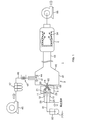
- FIG. 1 is a sectional view schematically showing the structure of a coating apparatus 1 according to the first embodiment of the present invention.
- the coating device 1 is a device that performs a coating process in which fine particles as a coating material are bonded to particles of raw material powder to generate composite powder (particles) having a coating layer formed on the surface.
- the coating device 1 includes a dispersion mixing unit 2, a transport unit 3, and a collection unit 4.
- the dispersion mixing unit 2, the transport unit 3, and the collection unit 4 are arranged side by side in a straight line.
- FIG. 2 is a top view of the dispersion mixing unit 2.
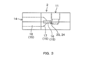
- FIG. 3 is a side view of the dispersion mixing unit 2. Below, the configuration of the dispersion mixing unit 2 will be described based on the state in which the dispersion mixing unit 2 is installed on a horizontal plane.
- the dispersion mixing section 2 has a rectangular parallelepiped outer shape.
- a slurry introduction port 11, a first air flow introduction port 12, and a second air flow introduction port 13 are formed on the upper surface of the dispersion mixing unit 2.
- the slurry introduction port 11, the first airflow introduction port 12, and the second airflow introduction port 13 are arranged in a straight line (hereinafter, the direction in which the slurry introduction port 11, the first airflow introduction port 12, and the second airflow introduction port 13 are arranged is “
- the first airflow inlet 12 and the second airflow inlet 13 are located on both sides of the slurry inlet 11 in the first horizontal direction.
- a powder flow discharge port 14 is formed on one side surface of the dispersion mixing unit 2 extending in the first horizontal direction.
- a slurry flow path 15 that connects the slurry inlet 11 and the powder flow outlet 14 is formed inside the dispersion mixing unit 2.
- the slurry flow path 15 extends downward from the slurry introduction port 11 and bends in a horizontal direction (hereinafter, this direction is referred to as a “second horizontal direction”) orthogonal to the first horizontal direction to the powder flow discharge port 14. It extends straight toward.
- the portion of the slurry flow path 15 extending in the second horizontal direction is continuous with the narrow road portion 16 having a relatively small vertical dimension and the narrow road portion 16, and has a vertical dimension toward the powder flow discharge port 14.
- a wide road portion 18 continuous with the wide road portion 17 and having a relatively large vertical dimension.
- the wide passage portion 18 is opened at the side surface of the dispersion mixing portion 2, and the opening is formed as the powder flow discharge port 14.
- a first flow path 21 communicating with the first air flow introduction port 12 and a second flow path 22 communicating with the second air flow introduction port 13 are formed.
- the first flow path 21 extends downward from the first air flow introduction port 12, bends in the horizontal direction, and extends toward the narrow path portion 16 of the slurry flow path 15.
- a first airflow injection port 23 is formed on the side surface of the narrow road portion 16, and the first flow path 21 communicates with the first airflow injection port 23.
- the first airflow injection port 23 is formed as a slit-shaped opening having an opening length in the vertical direction longer than the opening width in the horizontal direction, and the first flow path 21 flows as it approaches the first airflow injection port 23. The road section has been reduced.
- the second flow path 22 is formed symmetrically with the first flow path 21 with respect to a straight line that passes through the center of the slurry introduction port 11 and extends in the second horizontal direction. Specifically, the second flow path 22 extends downward from the second air flow introduction port 13, bends in the horizontal direction, and extends toward the narrow path portion 16 of the slurry flow path 15.
- a second air flow injection port 24 is formed on the side surface of the narrow path portion 16, and the second flow path 22 communicates with the second air flow injection port 24.
- the second airflow injection port 24 is formed as a slit-shaped opening having an opening length in the up-down direction that is longer than the opening width in the horizontal direction, and the second flow path 22 flows as it approaches the second airflow injection port 24.
- the road section has been reduced.
- the slurry inlet 11 is connected to one end of a slurry supply pipe 31.
- the other end of the slurry supply pipe 31 is connected to the slurry tank 32.
- a mixed material of raw material powder and a coating liquid containing a coating material is stored in a slurry state.
- the coating device 1 is used for producing the positive electrode active material powder for an all-solid-state battery.
- the raw material powder is a lithium metal composite oxide and has an average particle size of about 2 to 30 ⁇ m.
- the metal elements constituting the raw material powder include Co, Ni, Mn, Ti, Fe, Al and the like, but other elements may be included in order to improve the electrochemical characteristics.
- LiCoO 2 , LiNiO 2 , LiMn 2 O 4 , LiNi 1/3 Mn 1/3 Co 1/3 O 2 , Li 4 Ti 5 O 12 , LiFePO 4 , LiNi 0.8 Particles such as Co 0.15 Al 0.05 O 2 can be mentioned.
- the coating material is lithium niobate (LiNbO 3 ), and the coating liquid is an alkoxide solution serving as a precursor of lithium niobate.
- the coating apparatus 1 an alkoxide solution is attached to the surface of the particles of the raw material powder, and the alkoxide solution is dried to produce a powder in which the surface of the particles is coated with a precursor. Then, by firing the precursor at 250° C. or higher and lower than 500° C., it is possible to obtain a composite powder which is a positive electrode active material powder coated with a lithium niobate thin film.
- the coating material is not limited to lithium niobate, but is an insulating lithium composite oxide having the same effect, for example, lithium silicate, lithium borate, lithium titanate, lithium aluminate, lithium phosphate, or a composite thereof. Any material with high lithium ion conductivity, such as a compound, may be used.
- alkoxide in addition to ethoxide such as ethoxylithium, methoxide such as methoxylithium, various propoxylithium such as propoxylithium and butoxylithium and butoxide can be used, and the solvent is ethanol, methanol, various types.
- the alcohols such as propanol and butanol, an organic solvent can be used according to the purpose.
- an organic solvent for the coating solution it is desirable to use an organic solvent for the coating solution, but it is also possible to use an aqueous solution or a mixed solvent of an aqueous solution and an organic solvent by using a precursor having high stability to water.
- a method utilizing a water-soluble metal complex such as a peroxyniobate complex or a polyol synthesis method such as a glycol modification method, a MOD (Metal Organic Decomposition) method using an organic acid Various methods capable of forming an oxide thin film containing lithium, such as gelation method using a polysaccharide, LPD (Liquid Phase Deposition method), and CSD (Chemical Solution Deposition) method, can be used.
- the slurry is supplied from the slurry tank 32 to the slurry introduction port 11 through the slurry supply pipe 31 by the action of a pump or an ejector (not shown).
- the slurry introduced from the slurry introduction port 11 into the slurry flow channel 15 flows through the slurry flow channel 15 toward the powder flow discharge port 14.
- high-pressure fluid is supplied to the first airflow introduction port 12 and the second airflow introduction port 13 through the first supply pipe 33 and the second supply pipe 34, respectively.
- the airflow of the high-pressure fluid flows through the first flow path 21 and the second flow path 22, and is injected from the first airflow injection port 23 and the second airflow injection port 24 into the narrow passage portion 16 of the slurry flow path 15.
- the airflow injected from the first airflow injection port 23 and the second airflow injection port 24 has a maximum velocity of sound velocity or higher, that is, a maximum Mach number of 1 or higher, and a collision position set in the narrow road portion 16. Collide at P.
- the slurry When the slurry passes through the collision position P, it receives a shearing force from a flow velocity exceeding the sound velocity that collides at the collision position P, whereby the slurry is dispersed in a powder having a coating liquid adhered to the surface of the particles.
- the high-pressure fluid an inert gas such as nitrogen, carbon dioxide, or argon, or one in which the atmosphere is in a high-pressure gas state is used. Further, the high pressure fluid may be supplied in a supercritical state.
- the maximum velocity of the air stream to be jetted is preferably a Mach number of 1 to 4, but it may be lower than the speed of sound or higher than the Mach number of 4.
- the transport portion 3 includes a cylindrical portion 41 having a cylindrical peripheral surface, a truncated cone-shaped truncated cone 42 that is continuous with the cylindrical portion 41 and narrows as the distance from the truncated cone 41 increases, and a tubular portion extending from the truncated cone 42. And 43.
- the pipe part 43 may be a straight pipe, a spiral pipe, a cyclone pipe, or a combination thereof.
- Assist air introduction port 44 is formed on the peripheral surface of cylindrical portion 41. Assist air is supplied from the air supply source 45 to the assist air introduction port 44 through the assist air supply pipe 46.
- the air supply source 45 include a blower, a pump, an air compressor, a compressed gas cylinder, and the like.
- a mist separator (dryer) 47 that removes moisture from the air from the air supply source 45 and a heater 48 that heats the air from which the moisture has been removed by the mist separator 47 are interposed in the middle of the assist air supply pipe 46. Has been done. As a result, warm dry air is introduced into the cylindrical portion 41 from the assist air introduction port 44 as assist air. The temperature of the heated dry air is set within the temperature range of 60° C.
- the solvent of the coating liquid is ethanol.
- the boiling point of ethanol is preferably 78 ° C. or higher.
- various gases such as nitrogen, carbon dioxide, and an inert gas such as argon can be used as the assist air.
- the temperature of the heated air can be changed depending on the solvent, and is preferably the boiling point or higher. However, it is not limited to the above range and may be any number of times as long as it can supply the amount of heat required for drying.
- An airflow control member 51 is provided on the inner surface of the cylindrical portion 41 so as to face the assist air introduction port 44.
- the assist air introduced into the cylindrical portion 41 from the assist air introduction port 44 becomes a spiral air flow flowing along the inner peripheral surface of the cylindrical portion 41 by the action of the air flow control member 51, and becomes a truncated cone from the cylindrical portion 41.
- the part 42 and the pipe part 43 are passed in this order.
- a powder introduction port 52 is formed on the end face of the cylindrical portion 41.
- One end of a powder introduction path 53 is connected to the powder introduction port 52.
- the other end of the powder introduction passage 53 is connected to the powder flow outlet 14 of the dispersion mixing section 2, and the powder flow outlet 14 and the powder introduction outlet 52 are connected via the powder introduction passage 53. It is in communication.
- the powder generated in the dispersive mixing section 2 is discharged from the powder flow discharge port 14, flows through the powder introduction passage 53, and is introduced from the powder introduction port 52 into the cylindrical portion 41 of the transport section 3. .. Then, the powder introduced into the cylindrical portion 41 rides on the air flow of the assist air formed in the cylindrical portion 41 and is conveyed toward the pipe portion 43 through the conveying portion 3. During this transportation, the coating liquid adhering to the surfaces of the particles dries, whereby a powder in which the surfaces of the particles are coated with the precursor of the coating material is produced.
- the transport unit 3 may be heated by a heater or the like in order to accelerate the drying.
- the pipe portion 43 of the transport unit 3 is connected to the collection unit 4, and the inside of the transport unit 3 and the inside of the collection unit 4 communicate with each other.
- the air flow (powder flow) carrying the powder flowing through the transport unit 3 is introduced into the collection unit 4.
- a bag filter 54 is provided in the collection unit 4. The powder flow introduced into the collecting unit 4 passes through the bag filter 54. As a result, the powder is captured by the bag filter 54, and only the air flow from which the powder has been removed passes through the bag filter 54.
- the method of collecting powder by the collecting unit 4 is not limited to the method of using the bag filter 54, and may be a method of cyclone or a combination thereof. Further, a blower 55 may be connected to the collecting unit 4, and the function of the blower 55 may assist the discharge of the airflow from the collecting unit 4.
- the slurry (mixing material) in which the raw material powder and the coating liquid are mixed is dispersed in the powder having the coating liquid film adhered to the surface by the air flow of the high-pressure fluid. Therefore, the agglomeration of the raw material powder can be suppressed and the dispersibility can be improved. As a result, the powder coating process can be performed in a continuous process. Further, since the dispersion mixing unit 2 is not provided with a spray nozzle for injecting the coating liquid, there is no recovery loss due to powder adhering to the periphery of the spray nozzle, and the efficiency of the coating process (powder recovery efficiency) is improved. Can be made.
- the dispersion mixing unit 2 by supplying the raw material powder and the coating liquid in the state of slurry to the dispersion mixing unit 2, it is possible to increase the adhesion rate of the coating material to the particles serving as the main raw material.
- the dispersion mixing unit 2 has a slurry flow path 15 through which the slurry flows, and a first air flow injection port 23 and a second air flow injection port that blow out an air flow of a high-pressure fluid toward a collision position P set in the slurry flow path 15, respectively. 24 and.
- the slurry flowing through the slurry flow path 15 passes through the collision position P, the slurry can be favorably dispersed in the powder by receiving a shearing force from the air flow colliding at the collision position P.
- the transport unit 3 is formed with an assist air introduction port 44 for introducing an assist gas which is a heating and drying gas.
- an assist gas which is a heating and drying gas.
- Assist gas introduced from the assist air introduction port 44 into the transfer section 3 is introduced so as to flow along the inner peripheral surface of the transfer section 3. As a result, it is possible to prevent the powder from adhering to the inner peripheral surface of the transport unit 3, and it is possible to further improve the recovery efficiency of the powder.
- the dispersion mixing section 2, the transport section 3, and the collection section 4 are arranged side by side in a straight line. Therefore, the powder can be quickly transported, and the coating processing speed can be increased.
- FIG. 4 is a sectional view schematically showing the configuration of the coating apparatus 101 according to the second embodiment of the present invention. 4, parts corresponding to the respective parts shown in FIG. 1 are denoted by the same reference numerals as those parts. Further, in the following, the description of the parts having the same reference numerals is omitted.
- the transfer unit 102 includes a cylindrical main body 103 and a cylindrical tubular powder introduction passage 104 that is inserted into one end of the main body 103.
- One end of the powder introduction path 104 is opened as a powder introduction port 105 in the main body 103.
- the other end of the powder introduction path 104 is connected to the powder flow outlet 14 of the dispersion mixing section 2, and the powder flow outlet 14 and the powder introduction port 105 are connected via the powder introduction passage 104. It is in communication.
- the assist air introduction port 44 faces the tube wall of the powder introduction passage 104 in the radial direction of the main body 103 (direction orthogonal to the center line direction).
- the configuration of the coating device 101 can also have the same effect as the configuration of the coating device 1 shown in FIG.
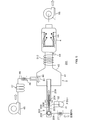
- FIG. 5 is a cross-sectional view schematically showing the configuration of the coating apparatus 201 according to the third embodiment of the present invention. 5, parts corresponding to the respective parts shown in FIG. 1 are denoted by the same reference numerals as those parts. Further, in the following, the description of the parts having the same reference numerals is omitted.
- the dispersion mixing section 202 is adopted instead of the dispersion mixing section 2.
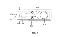
- FIG. 6 is a view of the dispersion mixing unit 202 as viewed from below.
- the dispersion mixing unit 202 is formed to be short in the first horizontal direction and long in the second horizontal direction.
- a flow path 203 extending in the second horizontal direction is formed in the dispersion mixing unit 202.
- One end of the flow path 203 is opened as a powder flow discharge port 204 on the side surface of the dispersion mixing unit 202 extending in the first horizontal direction.
- an airflow inlet 205 for supplying an airflow of the high-pressure fluid into the flow passage 203 and a downstream side of the airflow inlet 205 in the flow direction of the airflow are provided on the upper surface of the dispersion mixing unit 202.
- a slurry introduction port 206 for introducing the slurry is formed on the upper surface of the dispersion mixing unit 202.
- a Laval nozzle 207 is formed in the flow passage 203 at a midpoint between the air flow introduction port 205 and the slurry introduction port 206 by contracting and expanding the cross section of the flow passage.
- a slurry supply pipe 31 extending from the slurry tank 32 is connected to the slurry introduction port 206.
- the slurry supplied from the slurry tank 32 to the slurry introduction port 206 through the slurry supply pipe 31 is introduced from the slurry introduction port 206 into the flow path 203 and flows through the flow path 203 toward the powder flow discharge port 204.
- a supply pipe 208 is connected to the airflow introduction port 205, and the compressed gas (inert gas such as nitrogen, carbon dioxide, argon, etc., which is an example of a high-pressure fluid, or the atmosphere is in a high-pressure gas state through the supply pipe 208. Is supplied).
- the flow velocity of the compressed gas is greatly increased and reaches, for example, three times the speed of sound.
- the airflow having a flow velocity exceeding the sonic velocity flows over the slurry introduced into the flow path 203, the slurry receives shearing force from the airflow and is dispersed in the powder in which the coating liquid adheres to the surface of the particles.
- the powder flow outlet 204 is connected to one end of a powder introduction path 209.
- the powder introduction path 209 penetrates the end surface of the cylindrical portion 41 of the transfer section 3, and the other end portion is arranged inside the cylindrical portion 41.
- the powder introduction path 209 is formed so that the cross section of the flow path gradually increases from one end side toward the other end side (conveyance unit 3 side).
- the powder introduction path 209 may be heated by a heater in order to accelerate the drying of the powder.
- the compressed gas supplied to the dispersion mixing unit 202 may be heated by the heater 211.
- the temperature of the compressed gas may be set to be the same as the temperature of the heated drying air.
- the temperature of the compressed gas is preferably set higher than the boiling point of the solvent of the coating liquid.
- the powder generated in the dispersion mixing unit 202 is discharged from the powder flow discharge port 204, flows through the powder introduction passage 209, and is introduced into the cylindrical portion 41 of the transport unit 3. Then, the powder introduced into the cylindrical portion 41 rides on the air flow of the assist air formed in the cylindrical portion 41 and is conveyed toward the pipe portion 43 through the conveying portion 3. During this conveyance, the coating liquid adhering to the surface of the particles dries, and a powder in which the surface of the particles is coated with the precursor is produced. In order to accelerate the drying of the powder, the tube portion 43 of the transfer section 3 may be heated by the heater 212.
- the configuration of the coating apparatus 201 shown in FIG. 5 can also achieve the same operational effects as the configuration of the coating apparatus 1 shown in FIG.
- the compressed gas is heated by the heater 211, the temperature drop due to adiabatic expansion when the compressed gas is injected can be suppressed, and the drying can be performed efficiently without slowing down the drying speed.
- FIG. 7 is a cross-sectional view schematically showing the configuration of the coating apparatus 1 that employs the classifying unit 301. 7, parts corresponding to the respective parts shown in FIG. 1 are designated by the same reference numerals as those parts. Further, in the following, the description of the parts having the same reference numerals is omitted.
- the classification unit 301 may be adopted in order to selectively collect the composite powder having the coating layer formed on the surface.
- the classifying unit 301 is composed of a classifier and is provided between the transport unit 3 and the collecting unit 4.
- the air flow (powder flow) carrying the powder flowing through the transport unit 3 is introduced into the classifying unit 301.
- the classifying section 301 collects the composite powder having a relatively large particle size, and for example, the powder having a relatively small particle size such as the precursor of the coating material which has not been compounded is classified into the classifying section 301. And flows into the collection unit 4 and is collected by the collection unit 4.
- a cyclone is shown as the classifying unit 301, but what kind of classifier is adopted for the classifying unit 301 depends on the specific gravity and particle size of the powder collected in the classifying unit 301. It may be determined as appropriate. Further, a plurality of classifying units may be provided to carry out separation in multiple stages, and it is possible to separate into a plurality according to the level of the particle size. For example, unnecessary coarse particles such as agglomerated powder can be preliminarily separated. Further, it goes without saying that a classifier may be adopted not only in the coating apparatus 1 but also in the above-mentioned coating apparatuses 101 and 201.
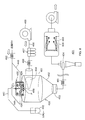
- FIG. 8 is a sectional view schematically showing the structure of a coating device 401 according to the fourth embodiment of the present invention.
- the coating device 401 includes a dispersion/mixing unit 402, a conveying unit 403, a classifying unit 404, and a collecting unit 405.
- FIG. 9 is an exploded perspective view of the dispersion mixing unit 402.
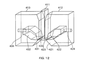
- the dispersion mixing unit 402 has a configuration in which the slurry flow pipe 411, the first airflow injector 412, and the second airflow injector 413 are sandwiched between two rectangular flat plate-shaped sandwiching plates 414.
- the slurry flow pipe 411 is a straight pipe extending straight, and a slurry-like coating liquid is discharged from the tip opening of the slurry flow pipe 411.
- the slurry flow pipe 411 is relatively movable in the longitudinal direction with respect to the first air stream jet body 412 and the second air stream jet body 413.
- the tip opening of the slurry flow pipe does not have to be a straight tube, and may be formed, for example, in a substantially conical shape whose diameter decreases toward the tip opening.
- the opening may be appropriately chamfered, curved or edged.
- the first airflow injector 412 and the second airflow injector 413 are arranged at positions symmetrical with respect to the center line of the slurry flow pipe 411 by 180 °.
- the first airflow ejector 412 is formed in a shape in which two corners on the side of the slurry flow pipe 411 are cut off in a triangular shape from a rectangular plate shape, and the lower part of the end face on the side of the slurry flow pipe 411 has a lower slurry. It has an inclined surface 421 that is inclined away from the distribution pipe 411.
- a pressure boosting chamber 422 is formed in the first airflow injector 412 so as to penetrate in the thickness direction.
- the pressurizing chamber 422 extends to the slurry flow pipe 411 side from an intermediate portion of the first air flow injector 412 in the direction opposite to the slurry flow pipe 411, is bent obliquely downward, and is positioned downward as it approaches the slurry flow pipe 411. Thus, it extends toward the inclined surface 421.
- a slit-shaped first air flow injection port 423 extending in the thickness direction is formed on the inclined surface 421, and the pressure increasing chamber 422 has a cross-sectional area that decreases toward the inclined surface 421, and the first air flow injection port 423 is formed. It is connected to the.
- a first airflow introduction path 424 is formed in the first airflow injection body 412. One end of the first airflow introduction path 424 is connected to the booster chamber 422, and the other end is open at the end surface of the first airflow injector 412 opposite to the slurry flow pipe 411 side.
- the second air stream injector 413 is formed symmetrically with the first air stream injector 412 with respect to the center line of the slurry flow pipe 411. That is, the second airflow injector 413 is formed in a shape in which two corners on the side of the slurry flow pipe 411 are cut off in a triangular shape from a rectangular plate shape, and the lower side of the end face on the side of the slurry flow pipe 411 is formed. It has an inclined surface 431 that inclines away from the slurry flow pipe 411. In addition, a pressure boosting chamber 432 is formed in the second air flow injector 413 so as to penetrate in the thickness direction.
- the pressurizing chamber 432 extends toward the slurry flow pipe 411 from a midway portion of the second air flow ejector 413 in the direction opposite to the slurry flow pipe 411, bends obliquely downward, and is located downward as it approaches the slurry flow pipe 411. Thus, it extends toward the inclined surface 431.
- the inclined surface 431 is formed with a slit-shaped second air flow injection port 433 extending in the thickness direction, and the pressure increasing chamber 432 has a cross-sectional area that decreases toward the inclined surface 431, and the second air flow injection port 433. It is connected to the.
- a second airflow introduction path 434 is formed in the second airflow injection body 413. One end of the second airflow introduction path 434 is connected to the booster chamber 432, and the other end is open at the end surface of the second airflow injector 413 opposite to the slurry flow pipe 411 side.
- the two sandwiching plates 414 collectively sandwich the slurry flow pipe 411, the first air stream jetting body 412 and the second air stream jetting body 413 between them. Both ends in the thickness direction of the pressurizing chamber 422 of the first air flow injector 412 are closed by sandwiching plates 414, respectively. Similarly, both ends of the booster chamber 432 of the second airflow injector 413 in the thickness direction are closed by the holding plate 414.
- one end of a slurry supply pipe 441 is connected to the upper end of the slurry flow pipe 411.
- the other end of the slurry supply pipe 441 is connected to the slurry tank 442.
- a mixed material of raw material powder and a coating liquid containing a coating material is stored in a slurry state.
- the slurry is supplied from the slurry tank 442 to the slurry flow pipe 411 through the slurry supply pipe 441.
- the slurry supplied to the slurry distribution pipe 411 flows through the slurry distribution pipe 411 and is discharged downward from the lower end of the slurry distribution pipe 411.
- the compressed gas nitrogen, carbon dioxide, argon, etc., which is an example of high pressure fluid
- the compressed gas nitrogen, carbon dioxide, argon, etc., which is an example of high pressure fluid
- Gas or air in a high-pressure gas state is supplied.
- the compressed gas flows through the first airflow introduction passage 424 and the second airflow introduction passage 434, and flows into the boost chambers 422 and 432 from the first airflow introduction passage 424 and the second airflow introduction passage 434, respectively.
- the air pressure in the pressure increasing chambers 422 and 432 rises, and the airflow is vigorously injected from the first airflow injection port 423 and the second airflow injection port 433.
- the slurry discharged from the lower end of the slurry flow tube 411 passes through the collision position P, it receives a shearing force from the airflow colliding at the collision position P and is dispersed in the powder in which the coating liquid adheres to the surface of the particles. ..
- the discharge position of the slurry supply pipe 411 can be adjusted in the vertical direction, and can be finely adjusted to the position most suitable for dispersion with respect to the collision position P.
- the transport unit 403 includes a cylindrical portion 451 having a cylindrical peripheral surface, a truncated cone-shaped conical portion 452 which is continuous with the cylindrical portion 451 and narrows away from the cylindrical portion 451, and a pipe portion which extends from the conical truncated portion 452. 453 and 453 are integrated.
- the pipe portion 453 may be a straight pipe, a spiral pipe, or a cyclone pipe.
- the transport unit 403 is arranged immediately below the dispersion mixing unit 402 such that the center line of the cylindrical portion 451 extends in the vertical direction.
- Assist air introduction port 454 is formed on the peripheral surface of cylindrical portion 451. Assist air is supplied to the assist air introduction port 454 from the air supply source 455 through the assist air supply pipe 456.
- the air supply source 455 include a blower, a pump, an air compressor, a compressed gas cylinder, and the like.
- a mist separator (dryer) 457 for removing water from the air from the air supply source 455 and a heater 458 for heating the air from which the water has been removed by the mist separator 457 are provided in the middle of the assist air supply pipe 456. Has been done. As a result, warming and drying air is introduced as assist air from the assist air introduction port 454 into the cylindrical portion 451.
- various gases such as nitrogen, carbon dioxide, and an inert gas such as argon can be used as the assist air.
- the assist air introduction port 454 and the assist air supply pipe 456 are formed so that the assist air is blown out from the assist air introduction port 454 in the tangential direction of the inner peripheral surface of the cylindrical portion 451. Therefore, the assist air introduced from the assist air introduction port 454 into the cylindrical portion 451 becomes a spiral airflow flowing along the inner peripheral surface of the cylindrical portion 451, and the cylindrical portion 451 to the truncated cone portion 452 and the pipe portion 453. Through in this order.
- a powder introduction port 459 is formed on the upper surface of the cylindrical portion 451.
- the powder generated in the dispersion mixing unit 402 is introduced into the cylindrical portion 451 of the conveying unit 403 through the powder introduction port 459. Then, the powder introduced into the cylindrical portion 451 rides on the air flow of the assist air formed in the cylindrical portion 451, and is conveyed toward the pipe portion 453 through the conveying portion 403. During this transfer, the coating liquid adhering to the surface of the particles dries to produce a powder in which the surface of the particles is coated with a precursor of a coating material.
- the transport unit 403 may be heated by the heater 461.
- the compressed gas supplied to the first airflow introduction passage 424 and the second airflow introduction passage 434 of the dispersion mixer 402 may be heated by the heater 462.
- the classification unit 404 is composed of a classification machine, and is provided between the transport unit 403 and the collection unit 405.
- the air flow (powder flow) carrying the powder flowing through the transport unit 403 is introduced into the classifying unit 404.
- the classifying unit 404 collects the composite powder having a relatively large particle size, and the powder having a relatively small particle size such as a precursor of a coating material containing no raw material powder is classified. It passes through the section 404 and flows into the collection section 405.
- a bug filter 463 is provided in the collection unit 405.
- the powder flowing into the collecting unit 405 is captured by the bag filter 463, and the bag filter 463 passes only the air flow from which the powder has been removed.
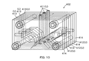
- the flow rate of the powder stream supplied from the dispersion/mixing section 402 to the conveying section 403 can be easily increased or decreased. That is, as shown in FIG. 10, the unit U (module) including the slurry flow pipe 411, the first airflow injection body 412, and the second airflow injection body 413 and the holding plate 414 can be alternately laminated. By increasing or decreasing the number of layers, the number of units, which is the number of units U provided in the dispersion mixing unit 402, can be increased or decreased, and the powder supplied from the dispersion mixing unit 402 to the transport unit 403 according to the number of units. The flow rate of body flow can be increased or decreased. In the laminated body of the unit U and the sandwiching plate 414, the sandwiching plates 414 are provided at both ends thereof.
- the total flow rate (total injection amount) of the airflows injected from the first airflow injection port 423 and the second airflow injection port 433 may be increased or decreased in proportion to the number of units.
- the flow rate of assist air (assist air amount) is also preferably increased or decreased in proportion to the number of units. In such a case, the flow rate (air amount) of air in the cylindrical portion 451 of the transport portion 403 increases or decreases in proportion to the number of units.
- the unit U (slurry flow pipe 411, first air flow jet body 412 and second air flow jet body 413). It is also possible to increase the flow rate of the powder stream supplied from the dispersion mixing section 402 to the conveying section 403 by increasing the thickness of the powder.
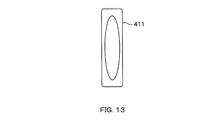
- the slurry flow pipe 411 may have an elliptical cross-sectional shape as shown in FIG. 13, and is shown in FIG. As described above, a plurality of ducts having a circular cross section may be formed.
- the slurry introduction port 11 may be formed on the side surface, and the slurry flow path 15 communicating the slurry introduction port 11 and the powder flow discharge port 14 may extend linearly.
- the slurry flow pipe 411 does not have to be tubular, and a flow path may be formed integrally with other members of the dispersion mixing unit 2.
- the present invention is not limited to the application in the production of the positive electrode active material powder for all-solid-state batteries, but may be applied to the manufacturing process of foods, pharmaceuticals, cosmetics, electronic parts and the like.
- the target particles are not limited to those used for the battery material, and the average particle size may be other than 2 to 30 ⁇ m.
Landscapes
- Chemical & Material Sciences (AREA)
- Chemical Kinetics & Catalysis (AREA)
- Organic Chemistry (AREA)
- Engineering & Computer Science (AREA)
- Manufacturing & Machinery (AREA)
- Electrochemistry (AREA)
- General Chemical & Material Sciences (AREA)
- Materials Engineering (AREA)
- Mechanical Engineering (AREA)
- Life Sciences & Earth Sciences (AREA)
- Wood Science & Technology (AREA)
- Inorganic Chemistry (AREA)
- Battery Electrode And Active Subsutance (AREA)
- Coating Apparatus (AREA)
- Glanulating (AREA)
- Nozzles (AREA)
- Inorganic Compounds Of Heavy Metals (AREA)
- Developing Agents For Electrophotography (AREA)
- Accessories For Mixers (AREA)
Priority Applications (7)
| Application Number | Priority Date | Filing Date | Title |
|---|---|---|---|
| JP2021503388A JP7586495B2 (ja) | 2019-03-01 | 2019-08-01 | 粉体のコーティング装置 |
| CN201980093161.0A CN113518662B (zh) | 2019-03-01 | 2019-08-01 | 粉体涂装装置和粉体涂装方法、粉体分散装置以及粉体分散方法 |
| EP19918302.1A EP3932533A4 (en) | 2019-03-01 | 2019-08-01 | POWDER COATING DEVICE AND COATING METHOD, POWDER DISPERSION DEVICE AND POWDER DISPERSION METHOD |
| US17/434,999 US12533648B2 (en) | 2019-03-01 | 2019-08-01 | Powder coating device and powder dispersion device |
| KR1020217029659A KR102708017B1 (ko) | 2019-03-01 | 2019-08-01 | 분체의 코팅 장치 및 코팅 방법, 분체 분산장치 및 분체 분산 방법 |
| US17/863,105 US12420252B2 (en) | 2019-03-01 | 2022-07-12 | Powder coating device and coating method, powder dispersion device, and powder dispersion method |
| JP2024106546A JP7851630B2 (ja) | 2019-03-01 | 2024-07-02 | 粉体のコーティング装置および粉体分散装置 |
Applications Claiming Priority (2)
| Application Number | Priority Date | Filing Date | Title |
|---|---|---|---|
| JP2019038048 | 2019-03-01 | ||
| JP2019-038048 | 2019-03-01 |
Related Child Applications (2)
| Application Number | Title | Priority Date | Filing Date |
|---|---|---|---|
| US17/434,999 A-371-Of-International US12533648B2 (en) | 2019-03-01 | 2019-08-01 | Powder coating device and powder dispersion device |
| US17/863,105 Division US12420252B2 (en) | 2019-03-01 | 2022-07-12 | Powder coating device and coating method, powder dispersion device, and powder dispersion method |
Publications (1)
| Publication Number | Publication Date |
|---|---|
| WO2020179100A1 true WO2020179100A1 (ja) | 2020-09-10 |
Family
ID=72338544
Family Applications (1)
| Application Number | Title | Priority Date | Filing Date |
|---|---|---|---|
| PCT/JP2019/030268 Ceased WO2020179100A1 (ja) | 2019-03-01 | 2019-08-01 | 粉体のコーティング装置およびコーティング方法、粉体分散装置ならびに粉体分散方法 |
Country Status (6)
| Country | Link |
|---|---|
| US (2) | US12533648B2 (https=) |
| EP (1) | EP3932533A4 (https=) |
| JP (1) | JP7586495B2 (https=) |
| KR (1) | KR102708017B1 (https=) |
| CN (1) | CN113518662B (https=) |
| WO (1) | WO2020179100A1 (https=) |
Cited By (1)
| Publication number | Priority date | Publication date | Assignee | Title |
|---|---|---|---|---|
| WO2022039263A1 (ja) * | 2020-08-20 | 2022-02-24 | 株式会社カワタ | 被膜溶液製造方法および被膜形成方法 |
Citations (7)
| Publication number | Priority date | Publication date | Assignee | Title |
|---|---|---|---|---|
| JPH02107366A (ja) | 1988-10-17 | 1990-04-19 | Nisshin Flour Milling Co Ltd | 粉体の液体コーティング装置 |
| JPH03135430A (ja) * | 1989-10-20 | 1991-06-10 | Freunt Ind Co Ltd | 造粒コーティング方法および装置 |
| JPH05208127A (ja) * | 1992-01-30 | 1993-08-20 | Nisshin Flour Milling Co Ltd | 微粒子コーティング方法および装置ならびに噴霧用ノズル |
| JP2003093865A (ja) * | 2001-09-27 | 2003-04-02 | Sekisui Chem Co Ltd | 微粒子の製造方法 |
| JP2003183022A (ja) * | 2001-10-11 | 2003-07-03 | Mitsubishi Chemicals Corp | リチウム遷移金属複合酸化物の製造方法 |
| JP2011056348A (ja) | 2009-09-07 | 2011-03-24 | Powrex Corp | 流動層処理方法及び流動層装置 |
| JP2013537470A (ja) * | 2010-05-28 | 2013-10-03 | サタ ゲーエムベーハー アンド カンパニー カーゲー | スプレー器具用ノズルヘッド |
Family Cites Families (31)
| Publication number | Priority date | Publication date | Assignee | Title |
|---|---|---|---|---|
| US2805639A (en) * | 1954-05-20 | 1957-09-10 | Pop Corn Inc | Apparatus for preparing popcorn and oil for inclusion in a film bag |
| NL246864A (https=) * | 1959-11-18 | |||
| GB1237144A (en) * | 1968-07-26 | 1971-06-30 | Pfizer Ltd | Coating method |
| US3983254A (en) * | 1973-12-07 | 1976-09-28 | Lever Brothers Company | Encapsulation particles |
| US4112130A (en) * | 1975-10-14 | 1978-09-05 | The Coca-Cola Company | Spray drying of orange juice |
| IT1150768B (it) * | 1982-04-06 | 1986-12-17 | Afros Spa | Procedimento ed apparecchiatura di miscelazione per la preparazione di materiali plastici a piu' componenti, in particolare poliuretanici |
| JPS6197068A (ja) * | 1984-10-17 | 1986-05-15 | Okawara Mfg Co Ltd | 連続流動層造粒装置における噴霧装置への粉粒体の付着防止方法 |
| JPH0716595B2 (ja) * | 1985-04-04 | 1995-03-01 | 山之内製薬株式会社 | 造粒コーティング方法及びその装置 |
| JP2718520B2 (ja) * | 1988-09-26 | 1998-02-25 | フロイント産業株式会社 | スプレーノズルおよびそれを用いた造粒コーディング装置 |
| US5230735A (en) | 1989-09-22 | 1993-07-27 | Nisshin Flour Milling Co., Ltd. | Apparatus for coating powder particles |
| DE69312941T2 (de) * | 1993-11-30 | 1998-03-12 | Alcan Int Ltd | Verfahren und Vorrichtung zur Trocknung von festem Material aus einer Suspension |
| US7125586B2 (en) * | 2003-04-11 | 2006-10-24 | Delphi Technologies, Inc. | Kinetic spray application of coatings onto covered materials |
| DE602004021219D1 (de) * | 2003-10-01 | 2009-07-09 | Ricoh Uk Products Ltd | Tonerherstellungsverfahren, Entwickler, Tonerbehälter, Prozesskartusche, Bilderzeugungsapparat und Bildherstellungsverfahren |
| US20060038044A1 (en) * | 2004-08-23 | 2006-02-23 | Van Steenkiste Thomas H | Replaceable throat insert for a kinetic spray nozzle |
| US20060040048A1 (en) * | 2004-08-23 | 2006-02-23 | Taeyoung Han | Continuous in-line manufacturing process for high speed coating deposition via a kinetic spray process |
| US7776503B2 (en) * | 2005-03-31 | 2010-08-17 | Ricoh Company, Ltd. | Particles and manufacturing method thereof, toner and manufacturing method thereof, and developer, toner container, process cartridge, image forming method and image forming apparatus |
| US7717968B2 (en) * | 2006-03-08 | 2010-05-18 | Yevgen Kalynushkin | Electrode for energy storage device and method of forming the same |
| DE102006047101B4 (de) * | 2006-09-28 | 2010-04-01 | Siemens Ag | Verfahren zum Einspeisen von Partikeln eines Schichtmaterials in einen Kaltgasspritzvorgang |
| KR100816293B1 (ko) * | 2007-04-02 | 2008-03-25 | 주식회사 탑 엔지니어링 | 분산액 코팅 장치 |
| DK2158029T3 (da) | 2007-04-10 | 2019-08-19 | Gea Process Eng Inc | Procesgasfilter og fremgangsmåde til rensning af dette |
| US7790344B2 (en) * | 2007-05-10 | 2010-09-07 | Ricoh Company Limited | Method of preparing powder and toner for electrophotography, and toner therefor |
| JP5260034B2 (ja) * | 2007-11-30 | 2013-08-14 | 三菱重工業株式会社 | 粉体分離装置及び固体燃料用バーナ |
| DE102008019682A1 (de) * | 2008-04-11 | 2009-10-15 | Siemens Aktiengesellschaft | Kaltgasspritzanlage |
| JP2011131168A (ja) | 2009-12-24 | 2011-07-07 | Fukuoka Prefecture | 噴霧造粒装置および噴霧造粒方法 |
| US8936830B2 (en) * | 2010-12-14 | 2015-01-20 | Femvix Corp. | Apparatus and method for continuous powder coating |
| US8715720B2 (en) * | 2011-09-14 | 2014-05-06 | Scott Murray | Cloud mixer and method of minimizing agglomeration of particulates |
| KR101482412B1 (ko) * | 2013-06-25 | 2015-01-13 | 주식회사 포스코 | 분말분사 코팅장치 |
| JP2015037009A (ja) * | 2013-08-12 | 2015-02-23 | 株式会社イズミフードマシナリ | カーボンを含有したスラリーの製造に用いる分散混合ポンプを備えた分散混合システム |
| CN111051268A (zh) * | 2017-07-25 | 2020-04-21 | 沙特基础工业全球技术公司 | 用于在机械搅拌混合器中对肥料材料进行涂覆的工艺 |
| US10804537B2 (en) | 2017-08-14 | 2020-10-13 | Global Graphene Group, Inc. | Protected particles of anode active materials, lithium secondary batteries containing same and method of manufacturing |
| DE102021107621A1 (de) * | 2021-03-26 | 2022-09-29 | Volkswagen Aktiengesellschaft | Verfahren zur Beschichtung eines Trägermaterials mit einem Aktivmaterial zur Herstellung einer Elektrodenfolie einer Batteriezelle |
-
2019
- 2019-08-01 JP JP2021503388A patent/JP7586495B2/ja active Active
- 2019-08-01 CN CN201980093161.0A patent/CN113518662B/zh active Active
- 2019-08-01 WO PCT/JP2019/030268 patent/WO2020179100A1/ja not_active Ceased
- 2019-08-01 KR KR1020217029659A patent/KR102708017B1/ko active Active
- 2019-08-01 US US17/434,999 patent/US12533648B2/en active Active
- 2019-08-01 EP EP19918302.1A patent/EP3932533A4/en active Pending
-
2022
- 2022-07-12 US US17/863,105 patent/US12420252B2/en active Active
Patent Citations (7)
| Publication number | Priority date | Publication date | Assignee | Title |
|---|---|---|---|---|
| JPH02107366A (ja) | 1988-10-17 | 1990-04-19 | Nisshin Flour Milling Co Ltd | 粉体の液体コーティング装置 |
| JPH03135430A (ja) * | 1989-10-20 | 1991-06-10 | Freunt Ind Co Ltd | 造粒コーティング方法および装置 |
| JPH05208127A (ja) * | 1992-01-30 | 1993-08-20 | Nisshin Flour Milling Co Ltd | 微粒子コーティング方法および装置ならびに噴霧用ノズル |
| JP2003093865A (ja) * | 2001-09-27 | 2003-04-02 | Sekisui Chem Co Ltd | 微粒子の製造方法 |
| JP2003183022A (ja) * | 2001-10-11 | 2003-07-03 | Mitsubishi Chemicals Corp | リチウム遷移金属複合酸化物の製造方法 |
| JP2011056348A (ja) | 2009-09-07 | 2011-03-24 | Powrex Corp | 流動層処理方法及び流動層装置 |
| JP2013537470A (ja) * | 2010-05-28 | 2013-10-03 | サタ ゲーエムベーハー アンド カンパニー カーゲー | スプレー器具用ノズルヘッド |
Non-Patent Citations (1)
| Title |
|---|
| See also references of EP3932533A4 |
Cited By (3)
| Publication number | Priority date | Publication date | Assignee | Title |
|---|---|---|---|---|
| WO2022039263A1 (ja) * | 2020-08-20 | 2022-02-24 | 株式会社カワタ | 被膜溶液製造方法および被膜形成方法 |
| JPWO2022039263A1 (https=) * | 2020-08-20 | 2022-02-24 | ||
| JP7803540B2 (ja) | 2020-08-20 | 2026-01-21 | 株式会社カワタ | 被膜溶液製造方法および被膜形成方法 |
Also Published As
| Publication number | Publication date |
|---|---|
| KR102708017B1 (ko) | 2024-09-19 |
| EP3932533A1 (en) | 2022-01-05 |
| US20220347642A1 (en) | 2022-11-03 |
| US20220134297A1 (en) | 2022-05-05 |
| US12420252B2 (en) | 2025-09-23 |
| KR20210124473A (ko) | 2021-10-14 |
| JPWO2020179100A1 (https=) | 2020-09-10 |
| JP2024138326A (ja) | 2024-10-08 |
| US12533648B2 (en) | 2026-01-27 |
| CN113518662B (zh) | 2023-12-12 |
| EP3932533A4 (en) | 2022-11-23 |
| JP7586495B2 (ja) | 2024-11-19 |
| CN113518662A (zh) | 2021-10-19 |
Similar Documents
| Publication | Publication Date | Title |
|---|---|---|
| KR101298162B1 (ko) | 냉가스 분무기 | |
| US9079209B2 (en) | Apparatus for power coating | |
| US9139912B2 (en) | Apparatus and method for continuous powder coating | |
| US6569245B2 (en) | Method and apparatus for applying a powder coating | |
| CN113438986B (zh) | 全固体电池的制造方法 | |
| WO2016082120A1 (en) | Combination of plasma coating and spray coating for lithium battery electrode fabrication | |
| US20230108347A1 (en) | Method for manufacturing secondary battery, or secondary battery | |
| CN100572584C (zh) | 用于气体动力施加涂层的装置和施加涂层的方法 | |
| US20130149471A1 (en) | Apparatus and method for continuous powder coating | |
| CN101460238B (zh) | 用于制造和/或预处理粉末状材料的方法和设备 | |
| JP7043774B2 (ja) | エアロゾル成膜装置、及びエアロゾル成膜方法 | |
| US12420252B2 (en) | Powder coating device and coating method, powder dispersion device, and powder dispersion method | |
| JP3853295B2 (ja) | 噴霧方法及び装置 | |
| JP7851630B2 (ja) | 粉体のコーティング装置および粉体分散装置 | |
| HK40051548A (en) | Powder coating device and coating method, powder dispersion device, and powder dispersion method | |
| CN115132955A (zh) | 用活性材料涂覆载体材料以制造电池单池的电极箔的方法 | |
| JP6347189B2 (ja) | 膜の製造装置、及び膜の製造方法 | |
| HK40051548B (zh) | 粉体涂装装置和粉体涂装方法、粉体分散装置以及粉体分散方法 | |
| JP2005290462A (ja) | エアロゾルデポジション装置 | |
| JP2024065781A (ja) | スラリー調製方法、スラリー調製装置、粉体製造方法、粉体製造システムおよびコーティング溶液調製方法 | |
| CN119426110A (zh) | 涂布装置和涂布方法 | |
| JP2013244457A (ja) | スプレーノズルおよび噴霧乾燥装置 | |
| JP7289584B1 (ja) | 大容量型超微粒化噴霧乾燥装置及び大容量型超微粒化噴霧乾燥方法 | |
| CN221816426U (zh) | 一种粉末输送装置、供粉装置及粉末喷涂系统 | |
| JP7803540B2 (ja) | 被膜溶液製造方法および被膜形成方法 |
Legal Events
| Date | Code | Title | Description |
|---|---|---|---|
| 121 | Ep: the epo has been informed by wipo that ep was designated in this application |
Ref document number: 19918302 Country of ref document: EP Kind code of ref document: A1 |
|
| ENP | Entry into the national phase |
Ref document number: 2021503388 Country of ref document: JP Kind code of ref document: A |
|
| NENP | Non-entry into the national phase |
Ref country code: DE |
|
| ENP | Entry into the national phase |
Ref document number: 20217029659 Country of ref document: KR Kind code of ref document: A |
|
| WWE | Wipo information: entry into national phase |
Ref document number: 2019918302 Country of ref document: EP |
|
| WWG | Wipo information: grant in national office |
Ref document number: 17434999 Country of ref document: US |