WO2020171199A1 - 赤外発光化合物、それを含有する発光性薄膜、発光性粒子、波長変換膜及び赤外発光面光源 - Google Patents
赤外発光化合物、それを含有する発光性薄膜、発光性粒子、波長変換膜及び赤外発光面光源 Download PDFInfo
- Publication number
- WO2020171199A1 WO2020171199A1 PCT/JP2020/007000 JP2020007000W WO2020171199A1 WO 2020171199 A1 WO2020171199 A1 WO 2020171199A1 JP 2020007000 W JP2020007000 W JP 2020007000W WO 2020171199 A1 WO2020171199 A1 WO 2020171199A1
- Authority
- WO
- WIPO (PCT)
- Prior art keywords
- group
- ring
- formula
- infrared
- aryl
- Prior art date
- Legal status (The legal status is an assumption and is not a legal conclusion. Google has not performed a legal analysis and makes no representation as to the accuracy of the status listed.)
- Ceased
Links
- 0 C1C2C(CC3)*C3CCCC12 Chemical compound C1C2C(CC3)*C3CCCC12 0.000 description 10
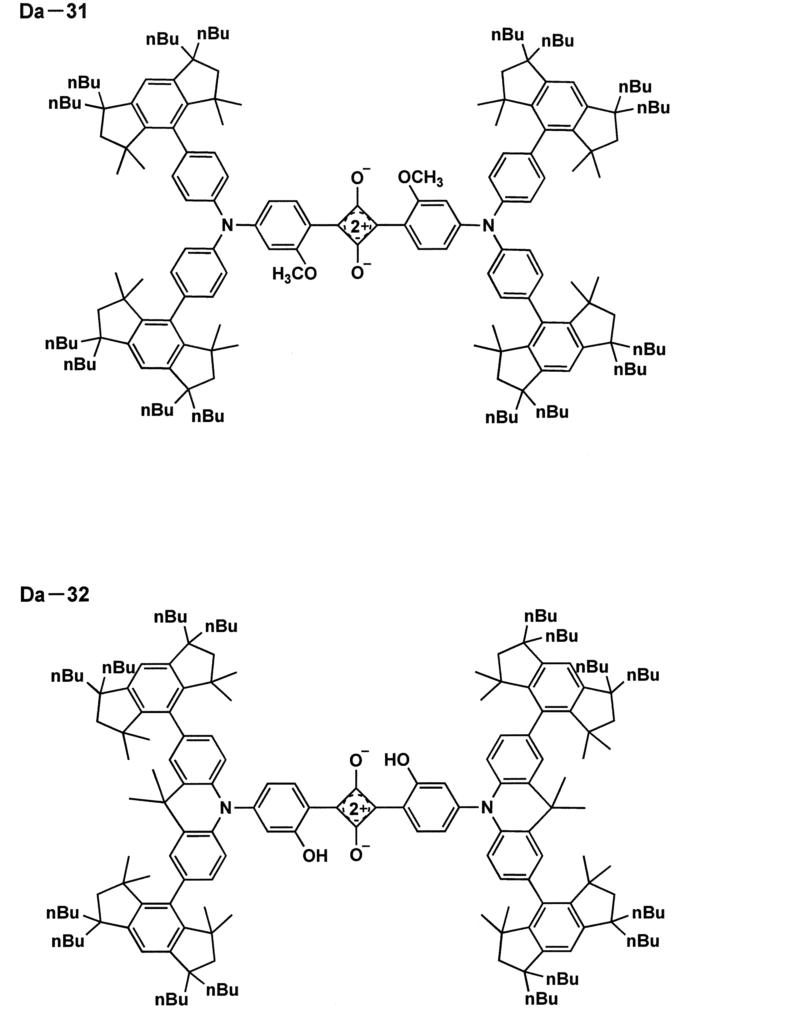
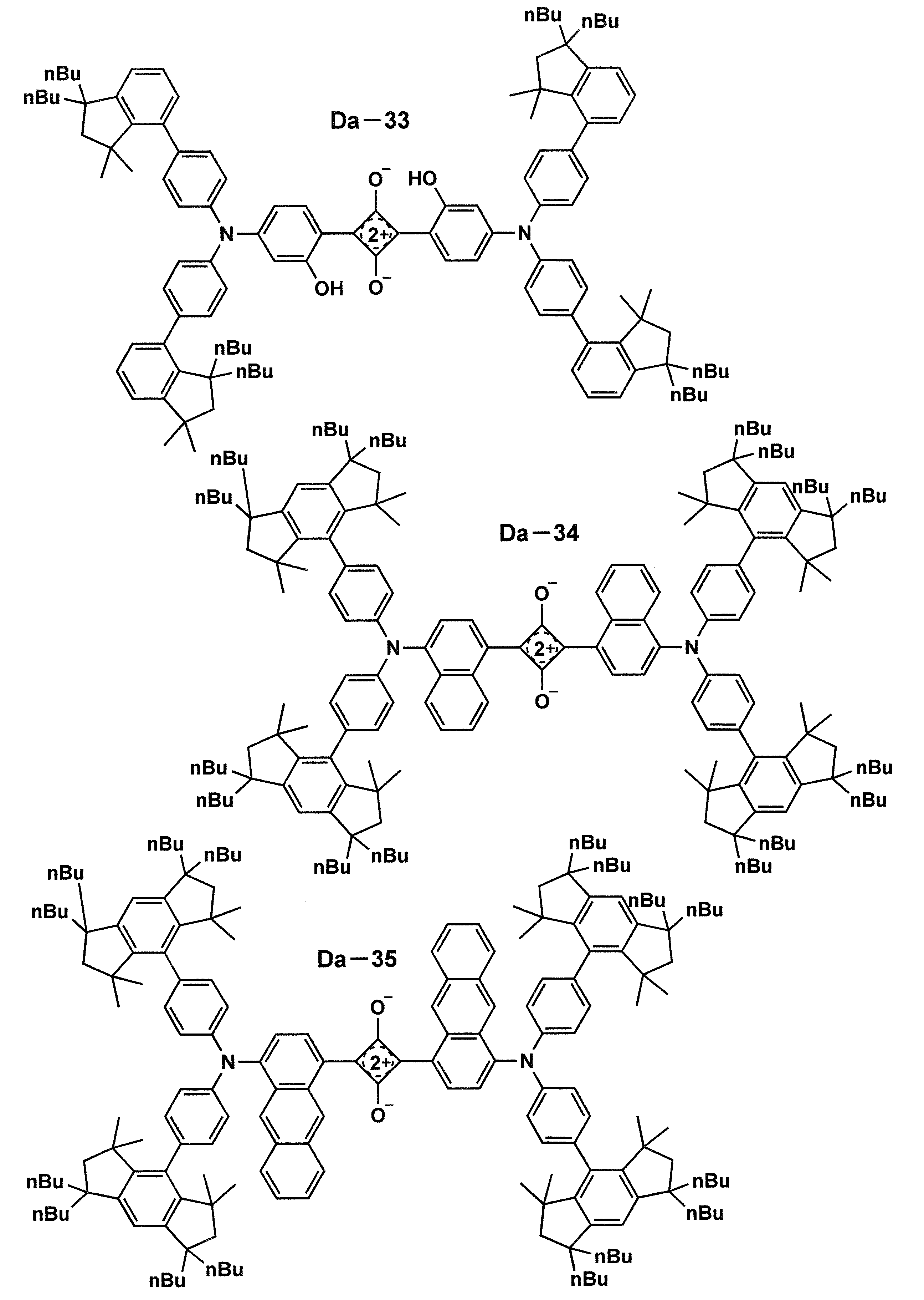
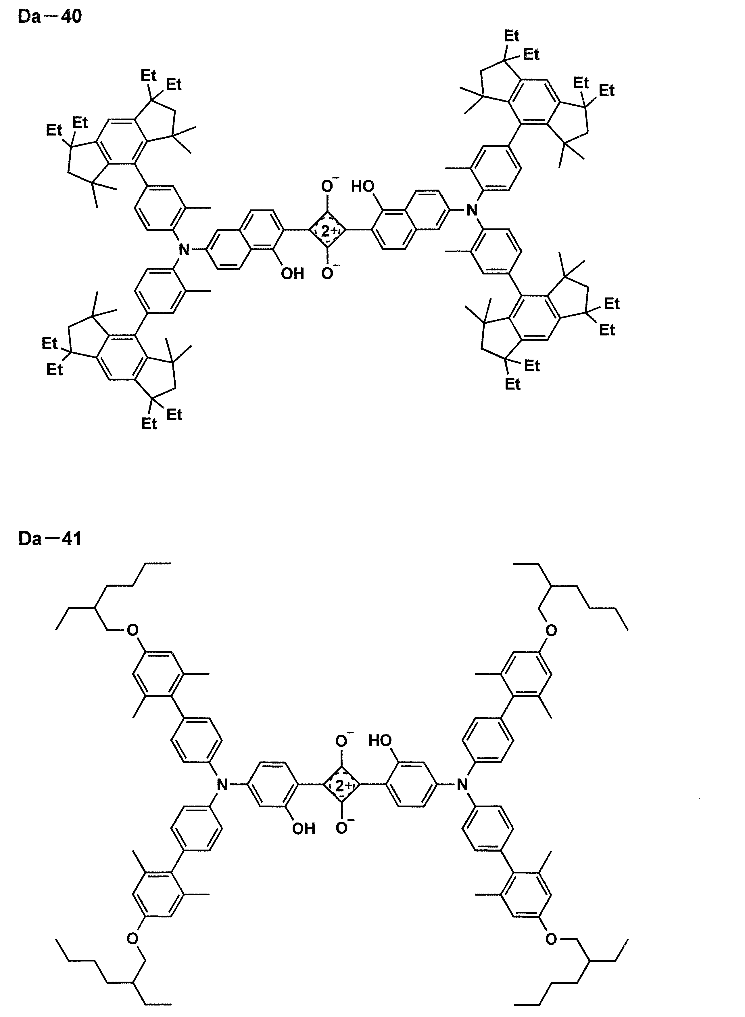
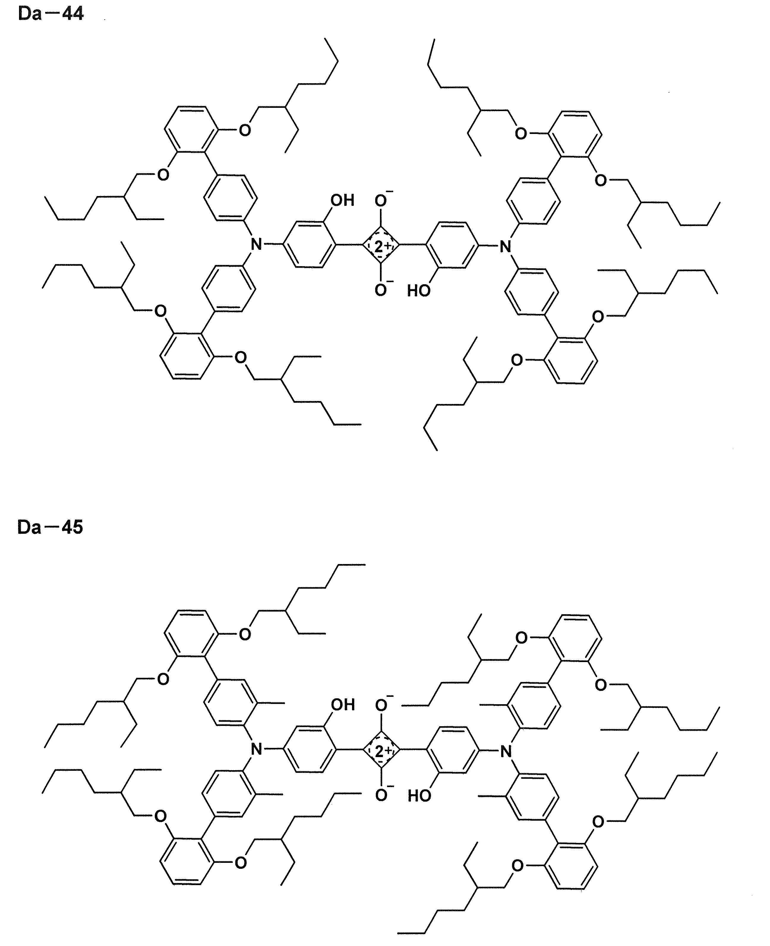
- FEEBRRFJCKRMJJ-UAHQZASESA-N CCCC(CCC)(CC1(C)C)c2c1c(-c(cc1)ccc1N(c(cc1)ccc1-c1c(C(C)(C)CC3(CCC)CCC)c3cc3c1C(C)(C)CC3(CCC)CCC)c(cc1)cc3c1c(O)c([C@H](C([C@]1(C)c(ccc4c5ccc(N(c(cc6)ccc6-c6c(C(C)(C)CC7(CCC)CCC)c7cc7c6C(C)(C)CC7(CCC)CCC)c(cc6)ccc6-c6c(C(C)(C)CC7(CCC)CCC)c7cc7c6C(C)(C)CC7(CCC)CCC)c4)c5O)[O-])C1[O-])cc3)c(C(C)(C)CC1(CCC)CCC)c1c2 Chemical compound CCCC(CCC)(CC1(C)C)c2c1c(-c(cc1)ccc1N(c(cc1)ccc1-c1c(C(C)(C)CC3(CCC)CCC)c3cc3c1C(C)(C)CC3(CCC)CCC)c(cc1)cc3c1c(O)c([C@H](C([C@]1(C)c(ccc4c5ccc(N(c(cc6)ccc6-c6c(C(C)(C)CC7(CCC)CCC)c7cc7c6C(C)(C)CC7(CCC)CCC)c(cc6)ccc6-c6c(C(C)(C)CC7(CCC)CCC)c7cc7c6C(C)(C)CC7(CCC)CCC)c4)c5O)[O-])C1[O-])cc3)c(C(C)(C)CC1(CCC)CCC)c1c2 FEEBRRFJCKRMJJ-UAHQZASESA-N 0.000 description 1
- XJUXIIXCYUVENW-DAPQOZDMSA-N CCCCCC(C)(C)c(c(CCCC)cc1c2C(C)(C)CC1(CCC)CCC)c2-c(cc1)ccc1N(c(cc1)ccc1-c1c(C(C)(C)CC2(CCC)CCC)c2cc2c1C(C)(C)CC2(CCC)CCC)c1cc(O)c([C@@H]([C@H](C2c(c(O)cc(N(c(cc3)ccc3-c3c(C(C)(C)CC4(CCC)CCC)c4cc4c3C(C)(C)CC4(CCC)CCC)c(cc3)ccc3-c3c(C(C)(C)CC4(CCC)CCC)c4cc4c3C(C)(C)CC4(CCC)CCC)c3)c3O)[O-])C2[O-])c(O)c1 Chemical compound CCCCCC(C)(C)c(c(CCCC)cc1c2C(C)(C)CC1(CCC)CCC)c2-c(cc1)ccc1N(c(cc1)ccc1-c1c(C(C)(C)CC2(CCC)CCC)c2cc2c1C(C)(C)CC2(CCC)CCC)c1cc(O)c([C@@H]([C@H](C2c(c(O)cc(N(c(cc3)ccc3-c3c(C(C)(C)CC4(CCC)CCC)c4cc4c3C(C)(C)CC4(CCC)CCC)c(cc3)ccc3-c3c(C(C)(C)CC4(CCC)CCC)c4cc4c3C(C)(C)CC4(CCC)CCC)c3)c3O)[O-])C2[O-])c(O)c1 XJUXIIXCYUVENW-DAPQOZDMSA-N 0.000 description 1
Images


Classifications
-
- C—CHEMISTRY; METALLURGY
- C09—DYES; PAINTS; POLISHES; NATURAL RESINS; ADHESIVES; COMPOSITIONS NOT OTHERWISE PROVIDED FOR; APPLICATIONS OF MATERIALS NOT OTHERWISE PROVIDED FOR
- C09K—MATERIALS FOR MISCELLANEOUS APPLICATIONS, NOT PROVIDED FOR ELSEWHERE
- C09K11/00—Luminescent materials, e.g. electroluminescent or chemiluminescent
- C09K11/06—Luminescent materials, e.g. electroluminescent or chemiluminescent containing organic luminescent materials
-
- C—CHEMISTRY; METALLURGY
- C07—ORGANIC CHEMISTRY
- C07C—ACYCLIC OR CARBOCYCLIC COMPOUNDS
- C07C211/00—Compounds containing amino groups bound to a carbon skeleton
- C07C211/43—Compounds containing amino groups bound to a carbon skeleton having amino groups bound to carbon atoms of six-membered aromatic rings of the carbon skeleton
- C07C211/54—Compounds containing amino groups bound to a carbon skeleton having amino groups bound to carbon atoms of six-membered aromatic rings of the carbon skeleton having amino groups bound to two or three six-membered aromatic rings
-
- C—CHEMISTRY; METALLURGY
- C09—DYES; PAINTS; POLISHES; NATURAL RESINS; ADHESIVES; COMPOSITIONS NOT OTHERWISE PROVIDED FOR; APPLICATIONS OF MATERIALS NOT OTHERWISE PROVIDED FOR
- C09B—ORGANIC DYES OR CLOSELY-RELATED COMPOUNDS FOR PRODUCING DYES, e.g. PIGMENTS; MORDANTS; LAKES
- C09B57/00—Other synthetic dyes of known constitution
-
- G—PHYSICS
- G02—OPTICS
- G02B—OPTICAL ELEMENTS, SYSTEMS OR APPARATUS
- G02B5/00—Optical elements other than lenses
- G02B5/20—Filters
-
- H—ELECTRICITY
- H05—ELECTRIC TECHNIQUES NOT OTHERWISE PROVIDED FOR
- H05B—ELECTRIC HEATING; ELECTRIC LIGHT SOURCES NOT OTHERWISE PROVIDED FOR; CIRCUIT ARRANGEMENTS FOR ELECTRIC LIGHT SOURCES, IN GENERAL
- H05B33/00—Electroluminescent light sources
- H05B33/12—Light sources with substantially two-dimensional [2D] radiating surfaces
-
- H—ELECTRICITY
- H10—SEMICONDUCTOR DEVICES; ELECTRIC SOLID-STATE DEVICES NOT OTHERWISE PROVIDED FOR
- H10H—INORGANIC LIGHT-EMITTING SEMICONDUCTOR DEVICES HAVING POTENTIAL BARRIERS
- H10H20/00—Individual inorganic light-emitting semiconductor devices having potential barriers, e.g. light-emitting diodes [LED]
- H10H20/80—Constructional details
- H10H20/85—Packages
- H10H20/851—Wavelength conversion means
- H10H20/8511—Wavelength conversion means characterised by their material, e.g. binder
- H10H20/8512—Wavelength conversion materials
-
- C—CHEMISTRY; METALLURGY
- C09—DYES; PAINTS; POLISHES; NATURAL RESINS; ADHESIVES; COMPOSITIONS NOT OTHERWISE PROVIDED FOR; APPLICATIONS OF MATERIALS NOT OTHERWISE PROVIDED FOR
- C09K—MATERIALS FOR MISCELLANEOUS APPLICATIONS, NOT PROVIDED FOR ELSEWHERE
- C09K2211/00—Chemical nature of organic luminescent or tenebrescent compounds
- C09K2211/10—Non-macromolecular compounds
- C09K2211/1018—Heterocyclic compounds
- C09K2211/1025—Heterocyclic compounds characterised by ligands
- C09K2211/1059—Heterocyclic compounds characterised by ligands containing three nitrogen atoms as heteroatoms
- C09K2211/107—Heterocyclic compounds characterised by ligands containing three nitrogen atoms as heteroatoms with other heteroatoms
-
- C—CHEMISTRY; METALLURGY
- C09—DYES; PAINTS; POLISHES; NATURAL RESINS; ADHESIVES; COMPOSITIONS NOT OTHERWISE PROVIDED FOR; APPLICATIONS OF MATERIALS NOT OTHERWISE PROVIDED FOR
- C09K—MATERIALS FOR MISCELLANEOUS APPLICATIONS, NOT PROVIDED FOR ELSEWHERE
- C09K2211/00—Chemical nature of organic luminescent or tenebrescent compounds
- C09K2211/10—Non-macromolecular compounds
- C09K2211/1018—Heterocyclic compounds
- C09K2211/1025—Heterocyclic compounds characterised by ligands
- C09K2211/1074—Heterocyclic compounds characterised by ligands containing more than three nitrogen atoms as heteroatoms
- C09K2211/1081—Heterocyclic compounds characterised by ligands containing more than three nitrogen atoms as heteroatoms with sulfur
-
- H—ELECTRICITY
- H10—SEMICONDUCTOR DEVICES; ELECTRIC SOLID-STATE DEVICES NOT OTHERWISE PROVIDED FOR
- H10K—ORGANIC ELECTRIC SOLID-STATE DEVICES
- H10K85/00—Organic materials used in the body or electrodes of devices covered by this subclass
- H10K85/60—Organic compounds having low molecular weight
- H10K85/649—Aromatic compounds comprising a hetero atom
- H10K85/652—Cyanine dyes
Definitions
- the present invention relates to an infrared light emitting compound, a light emitting thin film containing the same, a light emitting particle, a wavelength conversion film, and an infrared light emitting surface light source, and more specifically, enables long wavelength light emission and high light emission quantum yield. Infrared light emitting compounds and the like.
- infrared light emitting materials have been attracting a great deal of attention from the viewpoint of use in infrared cameras, biometric imaging, biometric sensing, and infrared communication.
- a pulse oximeter which is one of biometric sensing uses infrared light to calculate oxygen saturation in blood (see Non-Patent Document 1).
- it has been studied as a sensitizer for organic solar cells (see Non-Patent Document 2).
- a material with high brightness in a wavelength band of 650 to 900 nm called a “vital window” that easily penetrates a living body is preferably used.
- an infrared light emitting compound having a high molar extinction coefficient, a longer emission wavelength, and a high emission quantum yield is required.
- Non-Patent Document 3 describes squarylium compounds R-1 to R-3 having the following structures as examples of fluorescent dyes that emit infrared light.
- the maximum emission wavelength in the solution of R-1 is 721 nm and the emission quantum yield is 66%
- R-2 has a long emission wavelength up to 750 nm, but the emission quantum yield is 29% or less than half.
- R-3 has a maximum emission wavelength of 786 nm, but the emission quantum yield is drastically reduced to 2%. It is disclosed how it is difficult to achieve both long-wavelength light emission in the infrared region and high quantum yield.
- the near-infrared light has increased biological permeability as it gets closer to 900 nm, and it is especially useful in applications such as phototherapy and vein authentication, where the maximum exceeds 750 nm.
- an infrared light emitting compound having a long emission wavelength and capable of achieving both a high emission quantum yield.
- the present invention has been made in view of the above problems and circumstances, and a problem to be solved is to provide an infrared light emitting compound that enables long-wavelength light emission and high emission quantum yield.
- Another object of the present invention is to provide a light emitting thin film containing the same, a light emitting particle, a wavelength conversion film, and an infrared light emitting surface light source equipped with the wavelength conversion film.
- the present inventors have found that the above problems can be solved by introducing a specific substituent into an infrared light emitting compound in the process of examining the causes of the above problems, etc. .. That is, the above-mentioned subject concerning the present invention is solved by the following means.
- Ar and ring A each independently represent an aryl ring, a heteroaryl ring or a condensed ring thereof.
- Q-Ar represents an infrared-emitting residue.
- R 1 represents a group in which the dihedral angle between Ar and ring A is 45 degrees or more.
- the thick line represents a single bond or a double bond.
- Ar represents an aryl ring, a heteroaryl ring or a condensed ring thereof.
- Ring B represents an aromatic 6-membered ring.
- Ring C represents an aromatic five-membered ring.
- X 1's each independently represent an atom selected from a carbon atom, a nitrogen atom, an oxygen atom and a sulfur atom.
- X 2's each independently represent an atom selected from a carbon atom and a nitrogen atom.
- Q-Ar represents an infrared-emitting residue.
- R 1 represents a group in which the dihedral angle between Ar and ring B is 45 degrees or more.
- R 1 represents a group in which the dihedral angle between Ar and ring C is 45 degrees or more.
- R 11 represents a substituent, and adjacent R 1 or a plurality of R 11 may form a ring.
- n1 represents an integer of 0 to 4.
- n2 represents an integer of 0 to 3.
- Ar represents an aryl ring, a heteroaryl ring or a condensed ring thereof.
- Ring B represents an aromatic 6-membered ring.
- X 1's each independently represent an atom selected from a carbon atom, a nitrogen atom, an oxygen atom and a sulfur atom.
- Q-Ar represents an infrared-emitting residue.
- R 1 represents a group in which the dihedral angle between Ar and ring B is 45 degrees or more.
- R 2 and R 11 each independently represents a substituent, and R 1 or R 2 and the adjacent R 11, or a plurality of R 11 may be bonded with each other to form a ring.
- n3 and n4 each independently represent an integer of 0 to 3.
- each R 1 independently represents an alkyl group, an alkoxy group, an amino group, an aryl group, a heteroaryl group, a phenoxy group, an alkylthio group, a carbonyl group or a carboxy group.
- Infrared light emitting compound according to any one of items 1.
- each R 11 independently represents an alkyl group, an alkoxy group, an amino group, an aryl group, a heteroaryl group, a phenoxy group, an alkylthio group, a carbonyl group or a carboxy group.
- each R 2 independently represents an alkyl group, an alkoxy group, an amino group, an aryl group, a heteroaryl group, a phenoxy group, an alkylthio group, a carbonyl group or a carboxy group.
- External luminescent compound
- the infrared-emitting residue represented by Q-Ar is a residue of a squarylium dye, a dye containing benzobisthiadiazole, a dye containing thiadiazoloquinoxaline, a pyrromethene dye or a cyanine dye,
- the infrared light emitting compound according to any one of items 1 to 3.
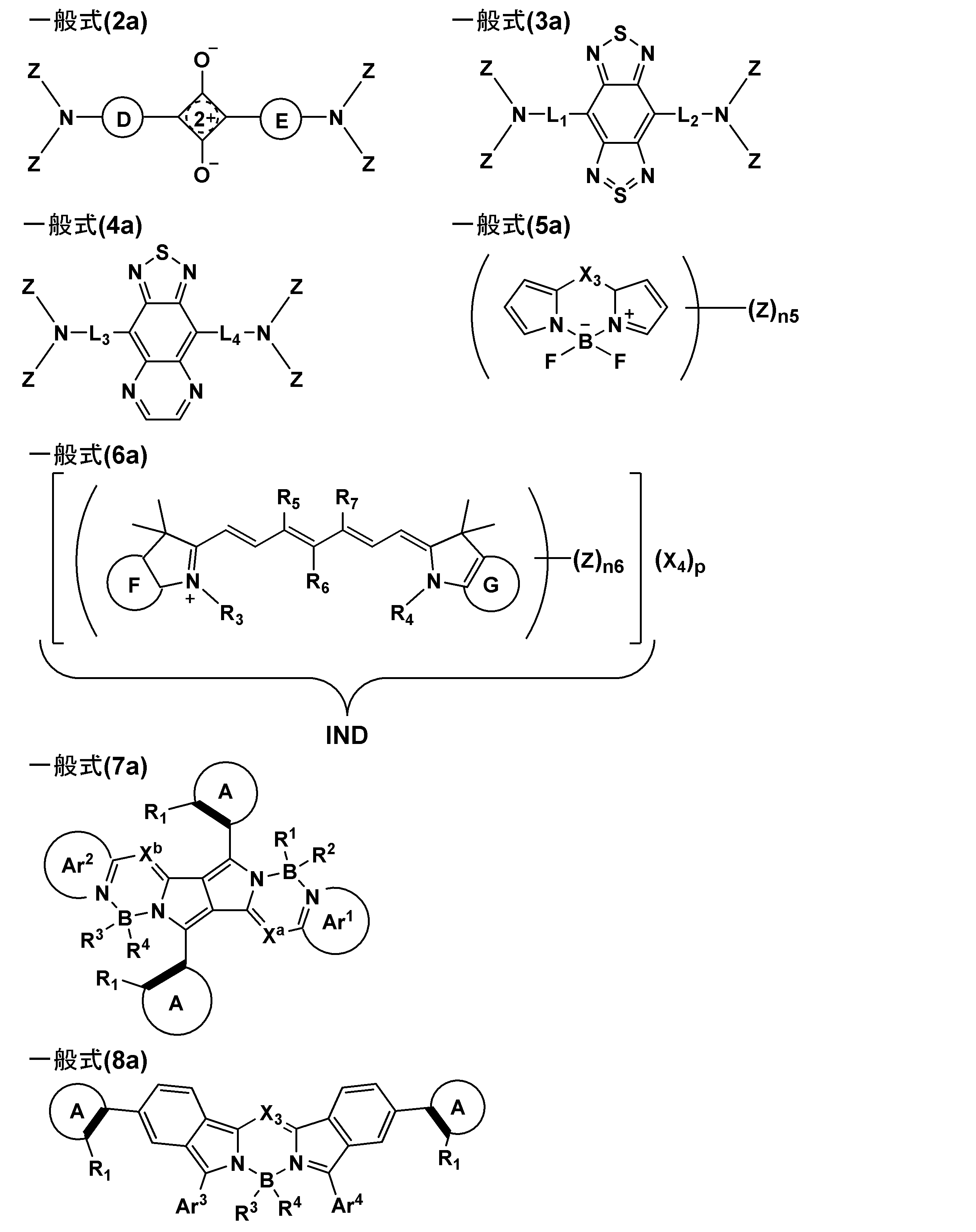
- the compound having the structure represented by the formula (1a) is represented by the following general formula (2a), (3a), (4a), (5a), (6a), (7a) or (8a).
- Ring D and ring E are each independently a hydroxy group, an alkoxy group, an NHCORa (Ra represents a hydrocarbon group) group, an NHSO 2 Rb (Rb represents a hydrocarbon group) group, or an NHPO(ORf)(.
- ORg) Rf and Rg each independently represent a hydrocarbon group
- Ring F and ring G each independently represent an aryl ring.
- L 1 to L 4 each independently represent an aryl ring, a heteroaryl ring or a single bond.
- X 3 represents a carbon atom or a nitrogen atom which may be substituted with an aryl group.
- R 3 and R 4 each independently represent an alkyl group which may be substituted with a sulfo group.
- R 5 and R 7 each independently represent a hydrogen atom or an alkyl group.
- R 6 represents a hydrogen atom or an aryl group, and when R 5 or R 7 represents an alkyl group, it may combine with R 5 or R 7 to form a cycloalkene ring.
- IND is a cation moiety
- X 4 represents a counter anion
- p represents a number necessary for neutralizing the charge
- the moiety represented by IND in the formula is an anion moiety.
- X 4 represents a counter cation
- p represents the number necessary for neutralizing the charge
- Ar 1 and Ar 2 each represent an aryl group having a 6-membered ring or a heteroaryl group having a 5-membered ring or a 6-membered ring, and these groups may have two or more rings.
- X a and X b each independently represent a nitrogen atom or CR 5
- R 5 represents a hydrogen atom or an electron withdrawing group.
- R 1 to R 4 are each independently a cyano group, a halogen, an alkyl group which may be substituted, an alkoxy group which may be substituted, an alkynyl group which may be substituted, or an aryl which may be substituted.
- Ar 3 and Ar 4 represent an aryl group having a 6-membered ring or a heteroaryl group having a 5-membered ring or a 6-membered ring, and these groups may be composed of two or more rings.
- Rings A each independently represent an aryl ring, a heteroaryl ring or a condensed ring thereof.
- R 1 represents a group having a dihedral angle of 45 degrees or more with the pyrrole ring or the benzene ring to which the ring A is bonded.
- the thick line represents a single bond or a double bond.
- Z represents the following formula (z) or a substituent, and at least one represents the formula (Z).
- n5 represents an integer of 1 to 4.
- n6 represents an integer of 1 to 4.
- ring A represents an aryl ring, a heteroaryl ring, or a condensed ring thereof. * Represents a binding site with Ar in the luminescent residue of formula (1a).
- R 1 represents a group in which the dihedral angle between Ar and ring A is 45 degrees or more.
- the thick line represents a single bond or a double bond.
- R 1 a to R 1 d, R 2 a to R 2 d, R 22 to R 24 , R 32 to R 34 , R 42 to R 44 , R 52 to R 54, and R 63 to R 66 are each independently.
- R 1 a is R 22
- R 2 a is R 24
- R 1 b is R 32
- R 2 b is R 34
- R 1 c is R 42
- R 2 c is R 44
- R 1 d may form a ring structure with R 52
- R 2 d may form a ring structure with R 54 .
- the ring H and the ring I are each independently a hydroxy group, an alkoxy group, an NHCORa (Ra represents a hydrocarbon group) group, an NHSO 2 Rb (Rb represents a hydrocarbon group) group or an NHPO(ORf)(. ORg) (Rf and Rg each independently represent a hydrocarbon group) represents an aryl ring which may be substituted with a group. )
- R 1 a to R 1 d and R 2 a to R 2 d are the same, and an alkyl group, an alkoxy group, a phenoxy group, an amino group or an aryl group is used.
- the ring H and the ring I are the same and represent an aryl group having a hydroxy group
- R 23 , R 33 , R 43 and R 53 are R 1 a to R 1 d and R 2 a to R 2 d are the same or represent a hydrogen atom, respectively, and R 1 a and R 2 a, R 1 b and R 2 b, R 1 c and R 2 c, At least one of the combinations of R 1 d and R 2 d is not a hydrogen atom
- R 22 , R 24 , R 32 , R 34 , R 42 , R 44 , R 52 and R 54 are The infrared luminescent compound according to item 9 or 10, which represents a hydrogen atom.
- ring H and ring I are the same and represent an aryl group having a hydroxy group, and R 1 a is R 22 and R 2 a is R 24.
- R 1 b is R 32
- R 2 b is R 34
- R 1 c is R 42
- R 2 c is R 44
- R 1 d is R 52
- R 2 d is R 54
- the infrared-emitting compound according to item 9 wherein the carbon chains are bonded to each other to form a 5-membered ring or 6-membered ring structure.
- a luminescent thin film comprising the infrared luminescent compound according to any one of items 1 to 12.
- a wavelength conversion film comprising the infrared light emitting compound according to any one of items 1 to 12.
- An infrared light emitting surface light source comprising the wavelength conversion film according to item 15.
- an infrared light emitting compound which enables long-wavelength light emission and high light emission quantum yield. Further, it is possible to provide an luminescent thin film containing the same, luminescent particles, a wavelength conversion film, and an infrared light emitting surface light source equipped with the wavelength conversion film.
- the emission quantum yield is extremely reduced. This is because the excited state in the light emission in the infrared region has a small energy difference from the ground state, so that the influence of non-radiative deactivation due to expansion and contraction of molecular bonds and vibration becomes large.
- a ⁇ -conjugated system is expanded while suppressing molecular vibration by introducing a substituent having a specific aromatic ring capable of generating a dihedral angle in the stable structure of the molecule into the infrared emission site, That is, they have found that both high emission quantum yield and long wavelength emission can be achieved in the infrared region.
- the nonradiative deactivation is suppressed by suppressing the rotation and movement between the Ar group of the general formula (1a) and the ring A by generating a dihedral angle in the stable structure of the molecule. ing. Further, to expand the ⁇ -conjugated system by forming a ⁇ - ⁇ conjugation between a group that causes a dihedral angle and a ⁇ -conjugated group that forms a dihedral angle (Ar group in the general formula (1a)). Have been successful. By introducing this substituent into, for example, a squarylium compound, it is possible to provide an infrared light emitting compound that can achieve both improved emission quantum yield and long-wavelength emission.
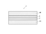
- Schematic sectional view showing an example of the configuration of an infrared light emitting surface light source including the wavelength conversion film of the present invention.
- Schematic sectional view showing an example of the configuration of the wavelength conversion film of the present invention having a sealing structure.
- the infrared light emitting compound of the present invention is characterized by having a structure represented by the above formula (1a).
- This feature is a technical feature common to or corresponding to each of the following embodiments.
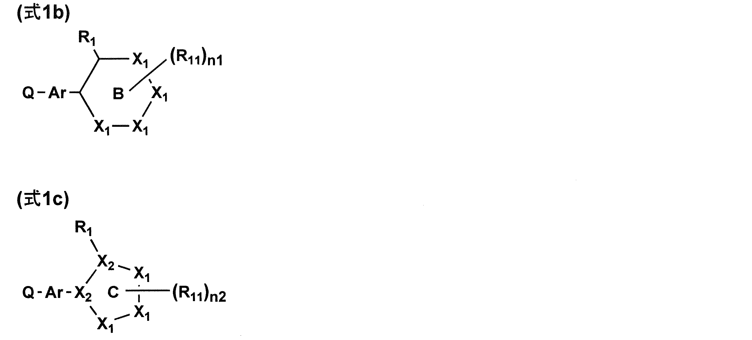
- the structure represented by the formula (1a) is preferably a structure represented by the formula (1b) or the formula (1c).
- the structure represented by the formula (1a) is preferably the structure represented by the formula (1d) or the formula (1e).
- R 1 represents an alkyl group, an alkoxy group, an amino group, an aryl group, a heteroaryl group, a phenoxy group, an alkylthio group, a carbonyl group or a carboxy group.
- each R 11 independently represents an alkyl group, an alkoxy group, an amino group, an aryl group, a heteroaryl group, a phenoxy group, an alkylthio group, a carbonyl group or a carboxy group.
- R 2 represents an alkyl group, an alkoxy group, an amino group, an aryl group, a heteroaryl group, a phenoxy group, an alkylthio group, a carbonyl group or a carboxy group, and it is between Ar and ring B in the above formula (1d).
- the fixation of the dihedral angle is made stronger, and the effect of enhancing the suppression of molecular vibration is obtained, which is preferable.
- the infrared-emitting residue represented by Q-Ar of the formula (1a) is a squarylium dye, a dye containing benzobisthiadiazole, a dye containing thiadiazoloquinoxaline, a pyrromethene dye or a cyanine dye.
- the compound having the structure represented by the formula (1a) has the structure represented by the general formula (2a), (3a), (4a), (5a), (6a), (7a) or (8a). It is preferable that the compound has.
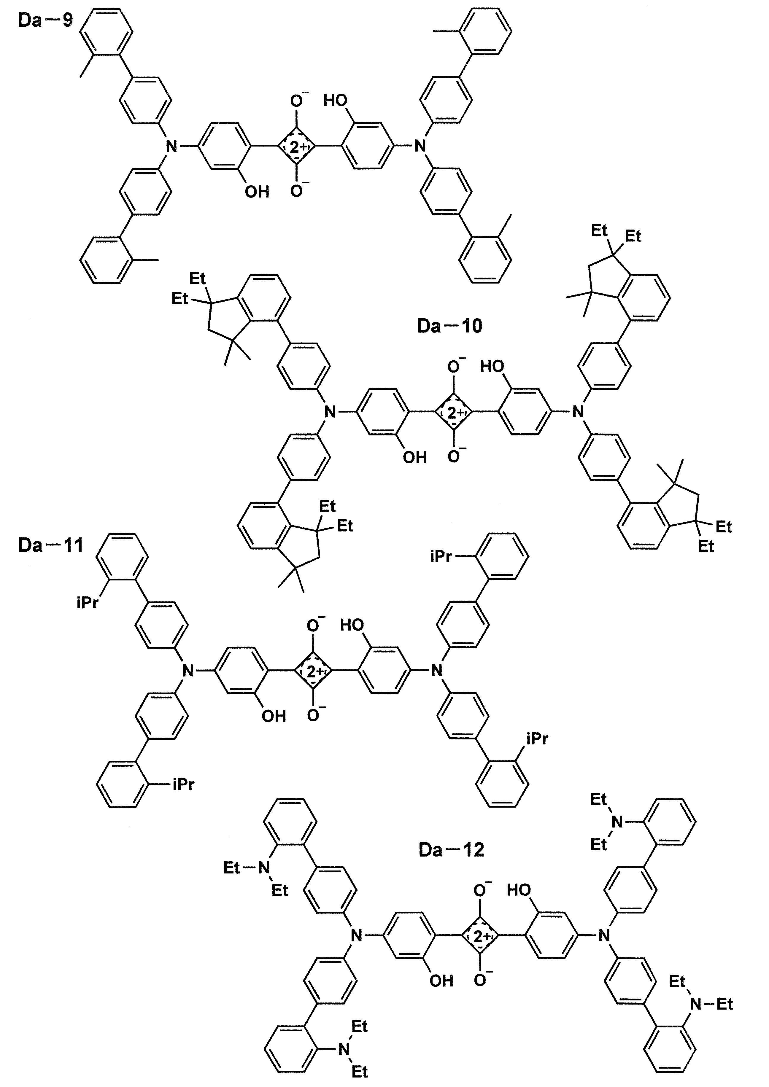
- the compound having the structure represented by the formula (1a) is preferably a squarylium compound having the structure represented by the general formula (2b).
- R 1 a to R 1 d and R 2 a to R 2 d are the same, and an alkyl group, an alkoxy group or a phenoxy group is used. It preferably represents a group, an amino group, an aryl group or a heteroaryl group.
- the ring H and the ring I are the same and represent an aryl group having a hydroxy group
- R 23 , R 33 , R 43 and R 53 are each R 1 a to R 1 d and R 2 a to R 2 d are the same or represent a hydrogen atom, but R 1 a and R 2 a, R 1 b and R 2 b, R 1 c and R 2 c, R At least one of the combination of 1 d and R 2 d is not a hydrogen atom
- R 22 , R 24 , R 32 , R 34 , R 42 , R 44 , R 52 and R 54 are each hydrogen. It preferably represents an atom.
- the ring H and the ring I are each independently a hydroxy group, an alkoxy group, an NHCORa (Ra represents a hydrocarbon group) group, an NHSO 2 Rb (Rb represents a hydrocarbon group) group or an NHPO(ORf)(.
- ORg) Rf and Rg each independently represent a hydrocarbon group
- Ring H and ring I are the same and represent an aryl group having a hydroxy group, wherein R 1 a is R 22 , R 2 a is R 24 , R 1 b is R 32 , and R 2 b is R 34 .
- R 1 c is bonded to R 42
- R 2 c is bonded to R 44
- R 1 d is bonded to R 52
- R 2 d is bonded to R 54 to form a 5-membered or 6-membered ring structure in the carbon chain.
- it is preferably a luminescent thin film, luminescent particles or a wavelength conversion film containing the infrared luminescent compound of the present invention.
- it is preferably an infrared light emitting surface light source including the wavelength conversion film.
- an infrared light emitting compound means the compound which has a light emission maximum wavelength over 700 nm.
- the infrared light emitting compound of the present invention is characterized by having a structure represented by the following formula (1a).
- Ar and ring A each independently represent an aryl ring, a heteroaryl ring or a condensed ring thereof.
- Q-Ar represents an infrared-emitting residue.
- R 1 represents a group in which the dihedral angle between Ar and ring A is 45 degrees or more.
- the thick line represents a single bond or a double bond.
- the infrared light emitting compound of the present invention preferably has a plurality of substituents according to the present invention.
- the number of the substituents according to the present invention can be, for example, 1 to 8 per molecule. It is preferably 1 to 4.
- the dihedral angle formed by Ar and ring A is 45 degrees or more, and more preferably 60 degrees or more.
- the upper limit is 90 degrees.
- Ar and ring A represent an aryl ring, a heteroaryl ring or a condensed ring thereof.
- aryl ring examples include, for example, benzene ring, indene ring, naphthalene ring, azulene ring, fluorene ring, phenanthrene ring, anthracene ring, acenaphthylene ring, biphenylene ring, chrysene ring, naphthacene ring, pyrene ring, pentalene ring, Aceanthrylene ring, heptalene ring, triphenylene ring, as-indacene ring, chrysene ring, s-indacene ring, pleiaden ring, phenalene ring, fluoranthene ring, perylene ring, acephenanthrylene ring, biphenyl ring, terphenyl ring, Examples thereof include a tetraphenyl ring.
- heteroaryl ring examples include a pyridine ring, a pyrimidine ring, a furan ring, a pyrrole ring, an imidazoline ring, a benzimidazoline ring, a pyrazole ring, a pyrazine ring, and a triazole ring (for example, 1,2,4-triazole ring, 1,2 , 3-triazole ring, etc.), pyrazolotriazole ring, oxazole ring, benzoxazole ring, thiazole ring, isoxazole ring, isothiazole ring, furazan ring, thiophene ring, quinoline ring, benzofuran ring, dibenzofuran ring, benzothiophene ring, Dibenzothiophene ring, indole ring, carbazole ring, carboline ring, diazacarbazole ring (in which one of the carbon carbon
- R 1 represents a group in which the dihedral angle between Ar and ring A is 45 degrees or more. Specifically, R 1 is not particularly limited as long as it is a group having a dihedral angle of 45 degrees or more as measured by a dihedral angle described later. Preferred are an alkyl group, an alkoxy group, an amino group, an aryl group, a heteroaryl group, a phenoxy group, an alkylthio group, a carbonyl group and a carboxy group.
- alkyl group examples include methyl group, ethyl group, n-propyl group, isopropyl group, n-butyl group, s-butyl group, t-butyl group, 2-ethylbutyl group, n-pentyl group, neopentyl group, n -Hexyl group, cyclohexyl group, 2-ethylhexyl group, n-heptyl group, n-octyl group, 2-butyloctyl group, 2-hexyloctyl group, n-nonyl group, n-decyl group, 2-hexyldecyl group, n-undecyl group, n-dodecyl group, 2-octyldodecyl group, n-tridecyl group, n-tetradecyl group, 2-decyltetradecyl group, n-
- alkoxy group examples include methoxy group, ethoxy group, n-propyloxy group, isopropyloxy group, n-butyloxy group, s-butyloxy group, t-butyloxy group, 2-ethylbutyloxy group, n-pentyloxy group.
- Neopentyloxy group n-hexyloxy group, cyclohexyloxy group, 2-ethylhexyloxy group, n-heptyloxy group, n-octyloxy group, 2-butyloctyloxy group, 2-hexyloctyloxy group, n- Nonyloxy group, n-decyloxy group, 2-hexyldecyloxy group, n-undecyloxy group, n-dodecyloxy group, 2-octyldodecyloxy group, n-tridecyloxy group, n-tetradecyloxy group, 2 -Decyltetradecyloxy group, n-pentadecyloxy group, n-hexadecyloxy group, n-heptadecyloxy group, n-octadecyloxy group, n-nonadecyl
- amino group examples include an amino group, an alkylamino group (eg, ethylamino group), a dialkylamino group (eg, dimethylamino group, diethylamino group, diisopropylamino group, di-n-propyl group, di-n-butylamino group, Di-s-butylamino group, di-2-ethylbutylamino group, di-2-ethylhexylamino group, didodecylamino group, dicyclopentylamino group, dicyclohexylamino group, etc.), arylamino group (phenylamino group, etc.) And diarylamino groups (diphenylamino group, dinaphthylamino group, etc.).
- alkylamino group eg, ethylamino group
- dialkylamino group eg, dimethylamino group, diethylamino group, diis
- Examples of the aryl group include groups obtained by removing one hydrogen atom from the above aryl ring.
- Examples of the heteroaryl group include groups obtained by removing one hydrogen atom from the above-mentioned heteroaryl ring.
- alkylthio group examples include a methylthio group, an ethylthio group, a propylthio group, a pentylthio group, a hexylthio group, an octylthio group and a dodecylthio group.
- Examples of the carbonyl group include an acyl group (eg, acetyl group, ethylcarbonyl group, n-propylcarbonyl group, cyclohexylcarbonyl group, etc.), and examples of the carboxy group include alkylcarboxy group (eg, methylcarboxy group, ethylcarboxy group). Groups, etc.), arylcarboxy groups (phenylcarboxy groups, etc.) and the like.
- acyl group eg, acetyl group, ethylcarbonyl group, n-propylcarbonyl group, cyclohexylcarbonyl group, etc.
- carboxy group include alkylcarboxy group (eg, methylcarboxy group, ethylcarboxy group). Groups, etc.), arylcarboxy groups (phenylcarboxy groups, etc.) and the like.
- Ar and ring A preferably represent an aryl ring, a heteroaryl ring or a condensed ring thereof, and more preferably an aryl ring.
- R 1 preferably represents an alkyl group, an alkoxy group, an amino group, an aryl group, a heteroaryl group, a phenoxy group, an alkylthio group, a carbonyl group or a carboxy group, more preferably an alkyl group, an alkoxy group or an amino group.
- Q-Ar represents an infrared-emitting residue.
- the preferred luminescent residue is preferably a group having a skeleton of a squarylium dye, a benzobisthiadiazole-containing dye, a thiadiazoloquinoxaline-containing dye, a pyrromethene dye or a cyanine dye. That is, the compound having the structure represented by the formula (1a) is preferably a squarylium dye, a dye containing benzobisthiadiazole, a dye containing thiadiazoloquinoxaline, a pyrromethene dye or a cyanine dye.
- the dihedral angle can be calculated as follows.
- R 1 represents a group in which the dihedral angle between Ar and ring A is 45 degrees or more.
- the dihedral angle of Ar and ring A in the present invention refers to the dihedral angle calculated by structural optimization by molecular orbital calculation.
- B3LYP is used as a functional
- 6-31G* is used as a basis function.
- Gaussian09 Revision C.01, MJ Frisch, et al, Gaussian, Inc., 2010. manufactured by Gaussian, USA can be used.
- the dihedral angle obtained by this calculation method represents a stable structure in the actual molecule.
- a C 1 -C 2 -C 5 -C 4 dihedral angle and a C 1 -C 2 -C 5 -C 6 dihedral angle The angle, the dihedral angle of C 3 -C 2 -C 5 -C 4 and the dihedral angle of C 3 -C 2 -C 5 -C 6 are shown from 0 to 90 degrees.
- the above structure optimization was performed using an initial structure having an average value of four dihedral angles of 0 degrees, and the resulting structure had a C 1 -C 2 -C 5 -C 4 dihedral angle.
- C 1 -C 2 -C 5 -C 6 dihedral angles, C 3 -C 2 -C 5 -C 4 dihedral angles, and C 3 -C 2 -C 5 -C 6 dihedral angles are averaged. Then, the dihedral angle according to the present invention can be calculated.
- the structure represented by the formula (1a) is preferably a structure represented by the following formula (1b) or formula (1c).
- Ar represents an aryl ring, a heteroaryl ring or a condensed ring thereof.
- Ring B represents an aromatic 6-membered ring.
- Ring C represents an aromatic five-membered ring.
- X 1's each independently represent an atom selected from a carbon atom, a nitrogen atom, an oxygen atom and a sulfur atom.
- X 2's each independently represent an atom selected from a carbon atom and a nitrogen atom.
- Q-Ar represents an infrared-emitting residue.
- R 1 represents a group in which the dihedral angle between Ar and ring B is 45 degrees or more.
- R 1 represents a group in which the dihedral angle between Ar and ring C is 45 degrees or more.
- R 11 represents a substituent, and adjacent R 1 or a plurality of R 11 may form a ring.
- n1 represents an integer of 0 to 4.
- n2 represents an integer of 0 to 3.
- Ring B represents an aromatic 6-membered ring. Specifically, it represents a six-membered ring group among the aryl ring and the heteroaryl ring mentioned in the formula (1a).
- Ring C represents an aromatic five-membered ring. Specifically, it represents a 5-membered ring group among the heteroaryl rings mentioned in the formula (1a).
- X 1's each independently represent an atom selected from a carbon atom, a nitrogen atom, an oxygen atom and a sulfur atom.
- X 2's each independently represent an atom selected from a carbon atom and a nitrogen atom.
- R 11 represents a substituent, and adjacent R 1 or a plurality of R 11 may form a ring. Examples of the substituent represented by R 11 are the same as those of R 1, and the same groups are preferable.
- n1 represents an integer of 0 to 4.
- n2 represents an integer of 0 to 3.
- the structure represented by the formula (1a) is preferably a structure represented by the following formula (1d) or formula (1e).
- Ar represents an aryl ring, a heteroaryl ring or a condensed ring thereof.
- Ring B represents an aromatic 6-membered ring.
- X 1's each independently represent an atom selected from a carbon atom, a nitrogen atom, an oxygen atom and a sulfur atom.
- Q-Ar represents an infrared-emitting residue.
- R 1 represents a group in which the dihedral angle between Ar and ring B is 45 degrees or more.
- R 2 and R 11 each independently represents a substituent, and R 1 or R 2 and the adjacent R 11, or a plurality of R 11 may be bonded with each other to form a ring.
- n3 and n4 each independently represent an integer of 0 to 3.
- R 2 examples include the same ones as R 1, and the same ones are preferable.
- R 2 represents a substituent.
- the substituent described in R 11 can be applied, but it represents an alkyl group, an alkoxy group, an amino group, an aryl group, a heteroaryl group, a phenoxy group, an alkylthio group, a carbonyl group or a carboxy group.
- n3 and n4 each represent an integer of 0 to 3.
- the compound having a structure represented by the formula (1a) has a structure represented by the following general formula (2a), (3a), (4a), (5a), (6a), (7a) or (8a). It is preferable that the compound has.
- the ring D and the ring E are each independently a hydroxy group, an alkoxy group, an NHCORa (Ra represents a hydrocarbon group) group, an NHSO 2 Rb (Rb represents a hydrocarbon group) group or an NHPO(ORf)(.
- ORg) Rf and Rg each independently represent a hydrocarbon group
- Ring F and ring G each independently represent an aryl ring.
- L 1 to L 4 each independently represent an aryl ring, a heteroaryl ring or a single bond.
- X 3 represents a carbon atom or a nitrogen atom which may be substituted with an aryl group.
- R 3 and R 4 each independently represent an alkyl group which may be substituted with a sulfo group.
- R 5 and R 7 each independently represent a hydrogen atom or an alkyl group.
- R 6 represents a hydrogen atom or an aryl group, and when R 5 or R 7 represents an alkyl group, it may combine with R 5 or R 7 to form a cycloalkene ring.
- IND is a cation moiety
- X 4 represents a counter anion
- p represents a number necessary for neutralizing the charge
- the moiety represented by IND in the formula is an anion moiety.
- X 4 represents a counter cation
- p represents the number necessary for neutralizing the charge
- Ar 1 and Ar 2 represent an aryl group consisting of a 6-membered ring or a heteroaryl group consisting of a 5-membered ring or a 6-membered ring, and these groups may consist of two or more rings.
- X a and X b each independently represent a nitrogen atom or CR 5
- R 5 represents a hydrogen atom or an electron withdrawing group.
- R 1 to R 4 are each independently a cyano group, a halogen, an alkyl group which may be substituted, an alkoxy group which may be substituted, an alkynyl group which may be substituted, or an aryl which may be substituted.
- Ar 3 and Ar 4 each represent an aryl group having a 6-membered ring or a heteroaryl group having a 5-membered ring or a 6-membered ring, and these groups may have two or more rings.
- Rings A each independently represent an aryl ring, a heteroaryl ring or a condensed ring thereof.
- R 1 represents a group having a dihedral angle of 45° or more with the pyrrole ring (general formula (7a)) or the benzene ring (general formula (8a)) to which the ring A is bonded.
- the thick line represents a single bond or a double bond.
- Z represents the following formula (Z) or a substituent, and at least one represents the formula (Z).
- n5 represents an integer of 1 to 4.
- n6 represents an integer of 1 to 4.
- ring A represents an aryl ring, a heteroaryl ring, or a condensed ring thereof. * Represents a binding site with Ar in the luminescent residue of formula (1a).
- R 1 represents a group in which the dihedral angle between Ar and ring A is 45 degrees or more.
- the thick line represents a single bond or a double bond.
- Ring D and ring E each independently represent an aryl ring which may be substituted with a hydroxy group or an alkoxy group.
- Ring F and ring G each independently represent an aryl ring.
- L 1 to L 4 each independently represent an aryl ring, a heteroaryl ring or a single bond.
- the aryl ring represented by the above rings D to G, and the aryl ring and the heteroaryl ring represented by L 1 to L 4 are those of the aryl ring or the heteroaryl ring described in the formula (1a). be able to.
- X 3 represents a carbon atom or a nitrogen atom which may be substituted with an aryl group.
- R 3 and R 4 each independently represent an alkyl group which may be substituted with a sulfo group.
- R 5 and R 7 each independently represent a hydrogen atom or an alkyl group.
- R 6 represents a hydrogen atom or an aryl group, and when R 5 or R 7 represents an alkyl group, it may combine with R 5 or R 7 to form a cycloalkene ring.
- n5 represents an integer of 1 to 4.
- n6 represents an integer of 1 to 4.
- Examples of counter cations are alkali metal ions (Li + , Na + , K + , Cs +, etc.), alkaline earth metal ions (Mg 2+ , Ca 2+ , Ba 2+ , Sr 2+, etc.), transition metal ions (Ag).
- counter anions examples include halogen ions (Cl ⁇ , Br ⁇ , I—), p-toluenesulfonate ion, ethyl sulfate ion, SO 4 2 ⁇ , SbF 6 ⁇ , PF 6 ⁇ , BF 4 ⁇ , B( C 6 F 5 ) 4 ⁇ , ClO 4 ⁇ , tris(halogenoalkylsulfonyl)methide anion (eg (CF 3 SO 2 ) 3 C ⁇ ), di(halogenoalkylsulfonyl)imide anion (eg (CF 3 SO 2 ) 2 N ⁇ ), tetracyanoborate anion and the like.
- halogen ions Cl ⁇ , Br ⁇ , I—
- p-toluenesulfonate ion ethyl sulfate ion
- SO 4 2 ⁇ SO 4 2 ⁇
- Z represents the above formula (z) or a substituent, and at least one represents the formula (Z).
- Ar the ring A, R 1 and bold lines, Ar of formula (1a), the same meaning as ring A, R 1 and bold lines.
- * Represents a binding site with Ar in the luminescent residue of formula (1a).
- R 5 is an electron withdrawing group
- the electron withdrawing group is not particularly limited, but a cyano group is preferable.
- the compound having the structure represented by the formula (1a) is preferably a squarylium compound having the structure represented by the following general formula (2b).
- R 1 a to R 1 d, R 2 a to R 2 d, R 22 to R 24 , R 32 to R 34 , R 42 to R 44 , R 52 to R 54, and R 63 to R 66 are each independently.
- R 1 a is R 22
- R 2 a is R 24
- R 1 b is R 32
- R 2 b is R 34
- R 1 c is R 42
- R 2 c is R 44
- R 1 d may form a ring structure with R 52
- R 2 d may form a ring structure with R 54 .
- the ring H and the ring I are each independently a hydroxy group, an alkoxy group, an NHCORa (Ra represents a hydrocarbon group) group, an NHSO 2 Rb (Rb represents a hydrocarbon group) group or an NHPO(ORf)(. ORg) (Rf and Rg each independently represent a hydrocarbon group) represents an aryl ring which may be substituted with a group. )
- R 1 a to R 1 d and R 2 a to R 2 d are the same, and an alkyl group, an alkoxy group, a phenoxy group, an amino group, an aryl group or It is preferred to represent a heteroaryl group.
- ring H and ring I are the same and represent an aryl group having a hydroxy group
- R 22 to R 24 , R 32 to R 34 , R 42 to R 44 and R 52 to R 54 are the same as or represent a hydrogen atom as the above R 1 a to R 1 d and R 2 a to R 2 d, and are the same as the above R 1 a and R 2 a, R 1 b.
- At least one of the combinations of R 2 b, R 1 c and R 2 c, and R 1 d and R 2 d is not a hydrogen atom, and is R 22 , R 24 , R 32 , R 34 , R 42 , R 44 , R 52 and R 54 preferably represent a hydrogen atom.
- ring H and ring I are the same and represent an aryl group having a hydroxy group, wherein R 1 a is R 22 , R 2 a is R 24 , R 1 b is R 32 , and R 2 b is R.
- R 1 c is R 42
- R 2 c is R 44
- R 1 d is R 52
- R 2 d is R 54
- they are a carbon chain having a 5-membered or 6-membered ring structure. Is preferably formed.
- the compounds represented by the general formula (3a), the general formula (4a), the general formula (5a), the general formula (6a), and the general formula (7a) according to the present invention can be prepared, for example, by the methods described in the following documents. For reference, it can be synthesized by similarly introducing the substituent according to the present invention. Nature Materials vol 15, 2016, p235-243 J. Phys. Chem. C 2009, 113, p1589-1595 Materials 2013, 6, p1779-1788 Moleculars 2018, 23, p226 Chem. Commun. , 2010, 46, p5289-5291
- the emission quantum yield ⁇ (%) is represented by the ratio of the number of photons absorbed and the number of photons emitted. If all of the excited molecules return to the ground state by fluorescence, the emission quantum yield ⁇ (%) will be 100%, but will not be 100% if non-radiative deactivation occurs.
- Non-radiative deactivation is a transition that returns to the ground state without emitting fluorescence, and in addition to relaxation to the triplet state due to intersystem crossing, the energy of the electronic state is converted into vibrational energy and finally becomes thermal energy. Internal conversion and energy transfer that transfers energy to other molecules. Letting Kf and Knr be the rate constants of the fluorescence transition and non-radiative transition of the molecule in the excited state, the emission quantum yield ⁇ (%) is
- the infrared light emitting compound of the present invention is a compound that emits fluorescence.
- the fluorescence spectrum of the infrared light emitting compound of the present invention can be confirmed by the following method.
- the infrared luminescent compound of the present invention is adjusted to 10 ⁇ 6 M in a toluene solution, and the fluorescence spectrum of this sample is measured at room temperature (300K).
- a spectrofluorometer (F7000, manufactured by Hitachi High-Technos) is used for measuring the emission spectrum. Further, it is an infrared luminescent compound that exhibits fluorescence emission with a maximum emission wavelength (wavelength at which emission intensity is maximum; also referred to as "emission peak wavelength”) exceeding 700 nm.
- the infrared luminescent compound of the present invention can exhibit long-wavelength luminescence and high luminescence quantum yield. Due to such properties, the infrared light emitting compound of the present invention can be used as a light emitting thin film, a light emitting particle, and a wavelength conversion film. For example, it can be used as a new type of dye for a fluorescent probe, a label in biology and medicine, and can be used for bioimaging. Further, the infrared-emitting compound of the present invention, in which the excited electron emits fluorescence as extra energy when returning to the ground state, has a wavelength conversion ability due to the difference in energy of absorption and emission, and a color conversion filter. Also, it can be used in dyes, pigments, optical filters, agricultural films and the like.
- the luminescent thin film of the present invention is characterized by containing the infrared luminescent compound of the present invention.
- the luminescent thin film of the present invention comprises forming a composition in which a dispersant is added to the infrared luminescent compound of the present invention for film-forming stability or the like, or a composition in which a solvent is further added to form a thin film. Can be manufactured by.
- dispersant examples include (meth)acrylate resin, polyester resin, polyamide resin, polyimide resin, polystyrene resin, polyepoxy resin, polyester resin, amino resin, fluorine resin, phenol resin, polyurethane.
- Resins polyethylene resins, polypropylene resins, polyvinyl chloride resins, polyvinyl alcohol resins, polyether resins, polyether ketone resins, polyphenylene sulfide resins, polycarbonate resins, aramid resins, etc., but are preferred.
- the (meth)acrylate-based resin is synthesized by homopolymerizing or copolymerizing various methacrylate-based monomers or acrylate-based monomers, and the desired (meth)acrylate is obtained by variously changing the monomer species and the monomer composition ratio.
- a system resin can be obtained. Further, in the present invention, it can be used by copolymerizing with a (meth)acrylate-based monomer together with a copolymerizable monomer having an unsaturated double bond other than the (meth)acrylate-based monomer. Can be used by mixing a plurality of other resins together with the poly(meth)acrylate resin.
- Examples of the monomer component forming the (meth)acrylate resin used in the present invention include (meth)acrylic acid, methyl (meth)acrylate, ethyl (meth)acrylate, propyl (meth)acrylate, butyl (meth)acrylate.
- the polystyrene resin is a homopolymer of a styrene monomer, or a random copolymer obtained by copolymerizing a monomer having another unsaturated double bond copolymerizable with the styrene monomer, a block copolymer, or a graft copolymer. Can be mentioned. Further, a blended product obtained by blending such a polymer with another polymer and a polymer alloy are also included.
- styrene monomer examples include styrene, ⁇ -methylstyrene, ⁇ -ethylstyrene, ⁇ -methylstyrene-p-methylstyrene, o-methylstyrene, m-methylstyrene, p-methylstyrene, etc.
- Nuclear halogenated styrenes such as styrene, o-chlorostyrene, m-chlorostyrene, p-chlorostyrene, p-bromostyrene, dichlorostyrene, dibromostyrene, trichlorostyrene, tribromostyrene, etc. are mentioned.
- Styrene and ⁇ -methylstyrene are preferred.
- the resin used in the present invention by homopolymerizing or copolymerizing these is, for example, a copolymer resin such as benzyl methacrylate/ethyl acrylate or butyl acrylate, or a copolymer resin such as methyl methacrylate/2-ethylhexyl methacrylate.
- Methylmethacrylate/methacrylic acid/stearylmethacrylate/acetoacetoxyethylmethacrylate copolymer resin Methylmethacrylate/methacrylic acid/stearylmethacrylate/acetoacetoxyethylmethacrylate copolymer resin, styrene/acetoacetoxyethylmethacrylate/stearylmethacrylate copolymer resin, and styrene/2-hydroxyethylmethacrylate/stearylmethacrylate copolymer resin
- copolymers and copolymer resins such as 2-ethylhexyl methacrylate/2-hydroxyethyl methacrylate.
- a preferable lower limit is 0.001 part by mass and a preferable upper limit is 50 parts by mass with respect to 100 parts by mass of the dispersant.
- the more preferable lower limit of the content of the light emitting material is 0.01 parts by mass
- the more preferable upper limit is 10 parts by mass
- the still more preferable lower limit is 0.05 parts by mass
- the further preferable upper limit is 8 parts by mass
- the particularly preferable lower limit is 0.1 part by mass. Parts by mass, especially preferred upper limit is 5 parts by mass.
- the luminescent thin film of the present invention can be appropriately used within a thickness range of 0.1 nm to 1 mm.
- the luminescent particles of the present invention are characterized by containing the infrared luminescent compound of the present invention. It may be a luminescent particle in which an infrared luminescent compound is adsorbed on the surface of the particle or a luminescent particle in which the infrared luminescent compound is included.
- a luminescent particle can be produced by aggregating an infrared luminescent compound in a polymer particle dispersion liquid in a liquid. Further, it may be a luminescent particle in which an infrared luminescent compound is encapsulated by using a swelling polymer in which the polymer particle absorbs the solvent and expands in volume when immersed in the solvent.
- the polymer particles commercially available products may be used, or those synthesized by a conventionally known method may be used.
- the conventionally known method is not particularly limited, and examples thereof include a dispersion polymerization method, a suspension polymerization method and an emulsion polymerization method, and the emulsion polymerization method is preferable.
- the monomer as the raw material of the polymer various monomers mentioned as the dispersant can be used.
- the solvent for aggregating the infrared luminescent compound in the polymer dispersion in liquid is not particularly limited. Known solvents can be used.
- the volume average particle diameter of the polymer particles is preferably in the range of 0.01 to 50 ⁇ m, more preferably 0.02 to 1 ⁇ m, and further preferably 0.04 to 0.5 ⁇ m.
- the volume average particle diameter within the above range allows the obtained luminescent particles to be applied to various uses.
- the volume average particle diameter can be specifically measured by a laser diffraction/scattered light particle size distribution measuring device, LS13320 model.
- the weight average molecular weight of the polymer particles is preferably in the range of 1,000 to 1,000,000, more preferably 5,000 to 800,000, and further preferably 10,000 to 600,000.
- the polymer particles contained in the luminescent particles of the present invention may be one kind or two or more kinds, but usually one kind.
- the wavelength conversion film of the present invention is characterized by containing the infrared light emitting compound of the present invention.
- the wavelength conversion film can be applied to an infrared light emitting surface light source that emits infrared light.
- the infrared light emitting surface light source of the present invention is characterized by including a wavelength conversion film.
- the infrared light emitting surface light source of the present invention is a light emitting member that emits infrared light and has a visible light region (380 to 1000 nm) including a near red light region, preferably a green to red region (including a near red light region).
- a surface light source such as an organic EL element, a micro LED, or an LED combined with a diffuser plate, which emits light in the red range (600 to 850 nm) including the near red range. It is preferable to absorb and emit near-infrared light, for example, in the region of more than 700 nm and 1500 nm or less.
- FIG. 1 shows a basic configuration of an infrared light emitting surface light source having the wavelength conversion film of the present invention.
- An infrared light emitting surface light source 1 shown in FIG. 1 is a surface light source 2 that emits visible light, for example, a visible light of the surface light source 2 that emits red light (R) in the near infrared on an organic EL element that emits red light.
- This is a configuration in which the wavelength conversion film 3 of the present invention for converting into light (IR) is arranged.
- the surface light source that emits visible light is a light source having at least the property of emitting red light, and is preferably a surface light source having a luminance uniformity of 70% or more when uniformly emitting light.
- the light source is preferably an organic electroluminescence element.
- a surface light source that emits visible light (red) is manufactured separately from a surface light source that emits visible light (red). It may be used by being stacked on a light source, or the wavelength conversion film may be laminated on a surface light source which emits visible light (red). Alternatively, it may also serve as an adhesive or a sealing film.
- the thickness of the infrared light emitting surface light source provided with the wavelength conversion film of the present invention is also appropriately determined depending on the application, but 0.1 to 1000 ⁇ m is preferable from the viewpoint of flexibility and downsizing, and It is preferably in the range of 1 to 500 ⁇ m.
- the infrared light emitting surface light source provided with the wavelength conversion film of the present invention is suitably used for biometric devices and biometric authentication devices.
- Example 1 ⁇ Dihedral angle>
- the dihedral angle was described above using Gaussian09 manufactured by Gaussian as the software for calculating the molecular orbital. Calculated under the conditions. The results are shown in Table I. In the case of the compound having no substituent according to the present invention, it is described as "-".
- the infrared emission compound of the present invention was adjusted to 10 ⁇ 6 M in a toluene solution, and the emission wavelength (fluorescence spectrum) of this sample at room temperature (300 K). was measured.
- a spectrofluorometer F7000, manufactured by Hitachi High-Technos
- the luminescence quantum yield of this solution was measured using an absolute PL quantum yield measuring device (C11347 manufactured by Hamamatsu Photonics KK). The emission wavelength was evaluated according to the following criteria.
- the emission quantum yield was a relative emission quantum yield when the emission quantum yield of R-6 was 1.0.
- FIG. 3 is a graph showing ⁇ PL and relative luminescence quantum yield for Comparative Compound R-6.
- a luminescent thin film of the present invention was prepared in the same manner except that the infrared luminescent compound Da-21 of the present invention was used instead of R-4 for comparison.
- the emission wavelength (fluorescence spectrum) and absolute PL quantum yield of these samples were measured at room temperature (300K).
- the emission wavelength was measured using a spectrofluorometer (F7000 manufactured by Hitachi High-Technos), and the absolute PL quantum yield was measured using an absolute PL quantum yield measuring device (C11347 manufactured by Hamamatsu Photonics). ..
- the absolute PL quantum yields of these R-4 light-emitting thin films when the absolute PL quantum yields in a toluene solution were set to 1.00 are shown below as relative values of the emission quantum yields. ..
- the light emitting thin film using the comparative compound R-4 maintained the emission quantum yield of 0.38 from the solution state, while the light emitting using the infrared light emitting compound Da-21 of the present invention. It was found that the organic thin film maintained the emission quantum yield of 0.80 in the solution state, and the concentration quenching was significantly suppressed. Furthermore, the luminescent thin film of Da-21 of the present invention showed light emission with a long wavelength of 20 nm or more and a higher luminescence quantum yield than the luminescent thin film of Comparative R-4.
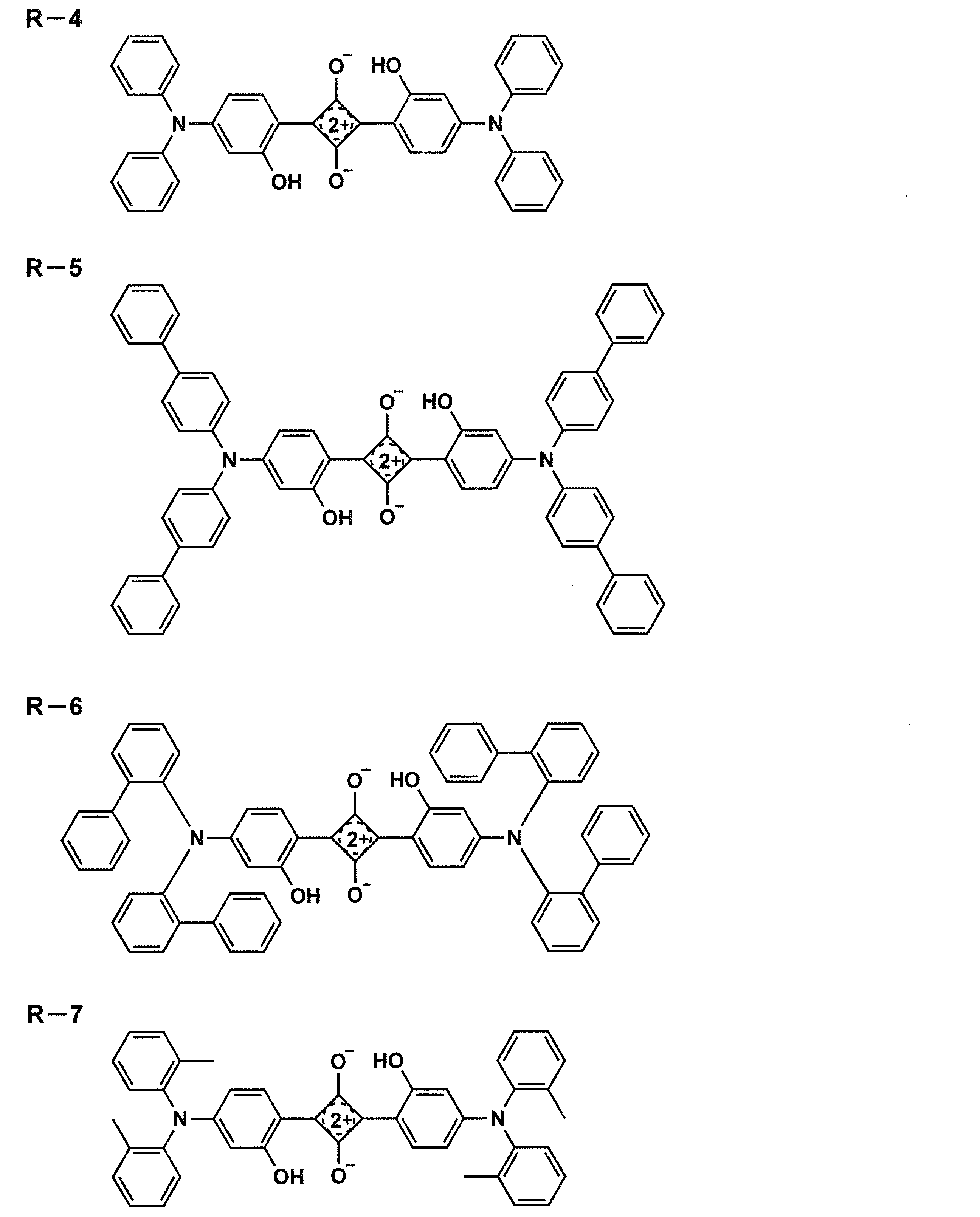
- (2)-2 Evaluation of Luminescent Thin Film of the Present Invention Comparison was carried out in the same manner as the comparative luminescent thin film described in (2)-1 except that R-4 of the comparative compound was changed to R-7 of the comparative compound.
- a luminescent thin film containing the compound R-7 was prepared.
- the light emitting thin film of the present invention was prepared in the same manner except that the infrared light emitting compounds Da-50 and Da-51 of the present invention were used instead of R-7 for comparison.
- the emission wavelength (fluorescence spectrum) and the emission quantum yield of these samples were measured in the same manner as in (2)-1.
- the relative values of the light emission quantum yields of these light emitting thin films when the light emission quantum yield in a toluene solution of each light emitting thin film is 1.00 are shown below.
- the luminescent thin film using the comparative compound R-7 maintained the quantum yield of 0.46 from the solution state, while the luminescent thin film using the infrared luminescent compound of the present invention was It was found that when the emission quantum yield was Da-50, the solution state was maintained at 0.76, and when Da-51 was maintained at 0.81, the concentration quenching was significantly suppressed. Further, the luminescent thin film of the present invention emitted light at a longer wavelength than the comparative luminescent thin film, and exhibited a high luminescence quantum yield. Similar results were obtained when the comparative compounds R-8 to R-10 were compared with the light emitting thin film using the infrared light emitting compound of the present invention.
- the comparative compounds R-8, R-9 and R-10 are the compounds described in the following documents, respectively.
- R-10 Chem. Eur. J. 2009, 15, 4857
- Example 2 Luminescent particles> Luminescent quantum yields in the luminescent particles of the infrared luminescent compound of the present invention and the comparative compound were measured.
- Luminescent Particles Polystyrene (PS) particle dispersion (solid content: 5.2% by mass, volume average particle diameter of polystyrene particles: 0.12 ⁇ m, dispersion medium: water) 96 ⁇ L, water 100 ⁇ L, nonionic interface 50 ⁇ L of a 2% aqueous solution of an activator (Kolliphor P407: manufactured by Sigma-Aldrich) and 100 ⁇ L of a 0.01 mmol/L THF solution of each compound shown in Table IV were added to prepare a mixed solution of polystyrene particles and each compound. Polystyrene particles were produced by stirring this mixed solution at 25° C. for 2 minutes.
- PEN polyethylene naphthalate film
- SiO x an atmospheric pressure plasma discharge treatment device having a configuration described in JP 2004-68143 A
- the obtained mixed solution was applied using an applicator on a gas barrier film having an inorganic gas barrier layer having a thickness of 500 nm. After drying at room temperature for 10 minutes, it was further heated and dried at 80° C. for 10 minutes to form a luminescent dye layer 5.
- the adhesive layer 6 was applied/formed on the gas barrier film 4B, laminated on the applied surface, and sealed using a vacuum laminator under heating conditions of 90°C. Then, the adhesive was cured by performing a heat treatment at 110° C. for 30 minutes, and the wavelength conversion film 3 was produced.
- the infrared light emitting surface light source 1 having the configuration shown in FIG. 1 was produced by bringing the light emitting surface of the organic EL element, which is a surface light source emitting red light (R), into close contact with the wavelength conversion film 3.
- the infrared light emitting compound of the present invention can enable long wavelength light emission and high light emission quantum yield. Therefore, it can be preferably applied to a light emitting thin film containing the infrared light emitting compound of the present invention, a light emitting particle, a wavelength conversion film, and an infrared light emitting surface light source equipped with the wavelength conversion film.
Landscapes
- Chemical & Material Sciences (AREA)
- Organic Chemistry (AREA)
- Engineering & Computer Science (AREA)
- Materials Engineering (AREA)
- Physics & Mathematics (AREA)
- General Physics & Mathematics (AREA)
- Optics & Photonics (AREA)
- Electroluminescent Light Sources (AREA)
- Optical Filters (AREA)
Abstract
Description
赤外発光の長波化と発光量子収率の向上に関する報告例は少ない。赤外発光を示す蛍光色素の例として、非特許文献2には、下記構造を有するスクアリリウム化合物R-1~R-3が記載されている。

すなわち、本発明に係る上記課題は、以下の手段により解決される。

Ar及び環Aは、それぞれ独立に、アリール環、ヘテロアリール環又はそれらの縮合環を表す。
Q-Arは、赤外発光性残基を表す。
R1は、Arと環Aの二面角が45度以上となる基を表す。
太線は、単結合又は二重結合を表す。)

Arは、アリール環、ヘテロアリール環又はそれらの縮合環を表す。
環Bは、芳香族六員環を表す。
環Cは、芳香族五員環を表す。
X1は、それぞれ独立に、炭素原子、窒素原子、酸素原子及び硫黄原子から選ばれる原子を表す。
X2は、それぞれ独立に、炭素原子及び窒素原子から選ばれる原子を表す。
Q-Arは、赤外発光性残基を表す。
R1は、Arと環Bの二面角が45度以上となる基を表す。またR1は、Arと環Cの二面角が45度以上となる基を表す。
R11は、置換基を表し、隣接するR1と、又は複数のR11同士が環を形成していてもよい。
n1は、0~4の整数を表す。n2は、0~3の整数を表す。)

Arは、アリール環、ヘテロアリール環又はそれらの縮合環を表す。
環Bは、芳香族六員環を表す。
X1は、それぞれ独立に、炭素原子、窒素原子、酸素原子及び硫黄原子から選ばれる原子を表す。
Q-Arは、赤外発光性残基を表す。
R1は、Arと環Bの二面角が45度以上となる基を表す。
R2及びR11は、それぞれ独立に、置換基を表し、R11と隣接するR1若しくはR2と、又は複数のR11同士が環を形成していてもよい。
n3及びn4は、それぞれ独立に、0~3の整数を表す。)
環D及び環Eは、それぞれ独立に、ヒドロキシ基、アルコキシ基、NHCORa(Raは炭化水素基を表す。)基、NHSO2Rb(Rbは炭化水素基を表す。)基又はNHPO(ORf)(ORg)(Rf及びRgは、それぞれ独立に、炭化水素基を表す。)基で置換されていてもよいアリール環を表す。
環F及び環Gは、それぞれ独立に、アリール環を表す。
L1~L4は、それぞれ独立に、アリール環、ヘテロアリール環又は単結合を表す。X3は、アリール基で置換されていてもよい炭素原子又は窒素原子を表す。
R3及びR4は、それぞれ独立に、スルホ基で置換されていてもよいアルキル基を表す。R5及びR7は、それぞれ独立に、水素原子又はアルキル基を表す。
R6は、水素原子又はアリール基を表し、R5又はR7がアルキル基を表すとき、R5又はR7と連結してシクロアルケン環を形成してもよい。
INDで表される部分がカチオン部である場合、X4は対アニオンを表し、pは電荷を中和するために必要な数を表し、式中のINDで表される部分がアニオン部である場合、X4は対カチオンを表し、pは電荷を中和するために必要な数を表し、式中のINDで表される部位の電荷が分子内で中和されている場合、pは0である。
Ar1及びAr2は、6員環からなるアリール基又は5員環若しくは6員環からなるヘテロアリール基を表し、これらの基は2個以上の環からなっていてもよい。
Xa及びXbは、それぞれ独立に、窒素原子又はCR5を表し、R5は、水素原子又は電子吸引基を表す。
R1~R4は、それぞれ独立に、シアノ基、ハロゲン、置換されていてもよいアルキル基、置換されていてもよいアルコキシ基、置換されていてもよいアルキニル基、置換されていてもよいアリール基又は置換されていてもよいヘテロアリール基を表す。
Ar3及びAr4は6員環からなるアリール基又は5員環若しくは6員環からなるヘテロアリール基を表し、これらの基は2個以上の環からなっていてもよい。
環Aは、それぞれ独立に、アリール環、ヘテロアリール環又はそれらの縮合環を表す。
R1は、それぞれ環Aが結合しているピロール環又はベンゼン環との二面角が45度以上となる基を表す。
太線は、単結合又は二重結合を表す。
Zは、下記式(z)又は置換基を表し、少なくとも一つは、式(Z)を表す。
n5は、1~4の整数を表す。n6は、1~4の整数を表す。)

*は、式(1a)の発光性残基中のArとの結合部位を表す。
R1は、Arと環Aの二面角が45度以上となる基を表す。
太線は、単結合又は二重結合を表す。)

R1a~R1d、R2a~R2d、R22~R24、R32~R34、R42~R44、R52~R54及びR63~R66は、それぞれ独立に、水素原子、アルキル基、アルコキシ基、フェノキシ基、アミノ基、アリール基又はヘテロアリール基を表すが、R1aとR2a、R1bとR2b、R1cとR2c、及びR1dとR2dの組み合わせの少なくとも一つは、ともに水素原子であることはない。
R1aはR22と、R2aはR24と、R1bはR32と、R2bはR34と、R1cはR42と、R2cはR44と、R1dはR52と、及びR2dはR54と環構造を形成していてもよい。
環H及び環Iは、それぞれ独立に、ヒドロキシ基、アルコキシ基、NHCORa(Raは炭化水素基を表す。)基、NHSO2Rb(Rbは炭化水素基を表す。)基又はNHPO(ORf)(ORg)(Rf及びRgは、それぞれ独立に、炭化水素基を表す。)基で置換されていてもよいアリール環を表す。)
本発明の実施態様としては、本発明の効果発現の観点から、前記式(1a)で表される構造が、前記式(1b)又は式(1c)で表される構造であることが好ましい。
また、前記式(1a)で表される構造が、前記式(1d)又は式(1e)で表される構造であることが好ましい。
本発明の実施態様としては、R11が、それぞれ独立に、アルキル基、アルコキシ基、アミノ基、アリール基、ヘテロアリール基、フェノキシ基、アルキルチオ基、カルボニル基又はカルボキシ基を表すことが好ましい。
さらに、本発明においては、式(1a)のQ-Arで表される赤外発光性残基が、スクアリリウム色素、ベンゾビスチアジアゾールを含む色素、チアジアゾロキノキサリンを含む色素、ピロメテン色素又はシアニン色素の残基であることが好ましい。
式(1a)で表される構造を有する化合物が、前記一般式(2a)、(3a)、(4a)、(5a)、(6a)、(7a)又は(8a)で表される構造を有する化合物であることが好ましい。
また、式(1a)で表される構造を有する化合物が前記一般式(2b)で表される構造を有するスクアリリウム化合物であることが好ましい。
一般式(2b)で表される構造を有するスクアリリウム化合物において、前記環Hと環Iは同一で、ヒドロキシ基を有するアリール基を表し、前記R23、R33、R43及びR53は、それぞれR1a~R1d及びR2a~R2dと同一又は水素原子を表すが、前記R1aとR2a、R1bとR2b、R1cとR2c、R1dとR2dの組み合わせの少なくとも一つは、ともに水素原子であることはなく、前記R22、R24、R32、R34、R42、R44、R52及びR54は、水素原子を表すことが好ましい。
さらに、前記一般式(2b)で表される構造を有するスクアリリウム化合物において、
環H及び環Iは、それぞれ独立に、ヒドロキシ基、アルコキシ基、NHCORa(Raは炭化水素基を表す。)基、NHSO2Rb(Rbは炭化水素基を表す。)基又はNHPO(ORf)(ORg)(Rf及びRgは、それぞれ独立に、炭化水素基を表す。)基で置換されていてもよいアリール環を表すことが好ましい。
環Hと環Iは同一で、ヒドロキシ基を有するアリール基を表し、前記R1aはR22と、R2aはR24と、R1bはR32と、R2bはR34と、R1cはR42と、R2cはR44と、R1dはR52と、R2dはR54と、それぞれ結合し、炭素鎖で5員環又は6員環構造を形成していることが好ましい。
また、本発明の赤外発光化合物を含有する発光性薄膜、発光性粒子又は波長変換膜であることが好ましい。さらに前記波長変換膜を具備する赤外発光面光源であることが好ましい。
なお、本発明において、赤外発光化合物とは、700nm超に発光極大波長を有する化合物をいう。
〔式(1a)で表される構造について〕
本発明の赤外発光化合物は、下記式(1a)で表される構造を有することを特徴とする。

Ar及び環Aは、それぞれ独立に、アリール環、ヘテロアリール環又はそれらの縮合環を表す。
Q-Arは、赤外発光性残基を表す。
R1は、Arと環Aの二面角が45度以上となる基を表す。
太線は、単結合又は二重結合を表す。)
アルキル基としては、例えば、メチル基、エチル基、n-プロピル基、イソプロピル基、n-ブチル基、s-ブチル基、t-ブチル基、2-エチルブチル基、n-ペンチル基、ネオペンチル基、n-ヘキシル基、シクロヘキシル基、2-エチルヘキシル基、n-ヘプチル基、n-オクチル基、2-ブチルオクチル基、2-ヘキシルオクチル基、n-ノニル基、n-デシル基、2-ヘキシルデシル基、n-ウンデシル基、n-ドデシル基、2-オクチルドデシル基、n-トリデシル基、n-テトラデシル基、2-デシルテトラデシル基、n-ペンタデシル基、n-ヘキサデシル基、n-ヘプタデシル基、n-オクタデシル基、n-ノナデシル基、n-イコシル基等が挙げられる。
ヘテロアリール基としては、上述したヘテロアリール環から水素原子を1個除いた基が挙げられる。
本発明において二面角は以下のようにして算出することができる。
一般式(1a)において、R1はArと環Aの二面角が45度以上となる基を表す。本発明におけるArと環Aの二面角とは、分子軌道計算による構造最適化により算出される二面角をいう。具体的には、構造最適化を行う分子軌道計算において、汎関数としてB3LYP、基底関数として6-31G*を用いて導かれる。分子軌道計算用ソフトウェアとしては、米国Gaussian社製のGaussian09(Revision C.01,M.J.Frisch,et al,Gaussian,Inc.,2010.)を利用することができる。この計算方法で得られる二面角は、実際の分子での安定構造を表している。

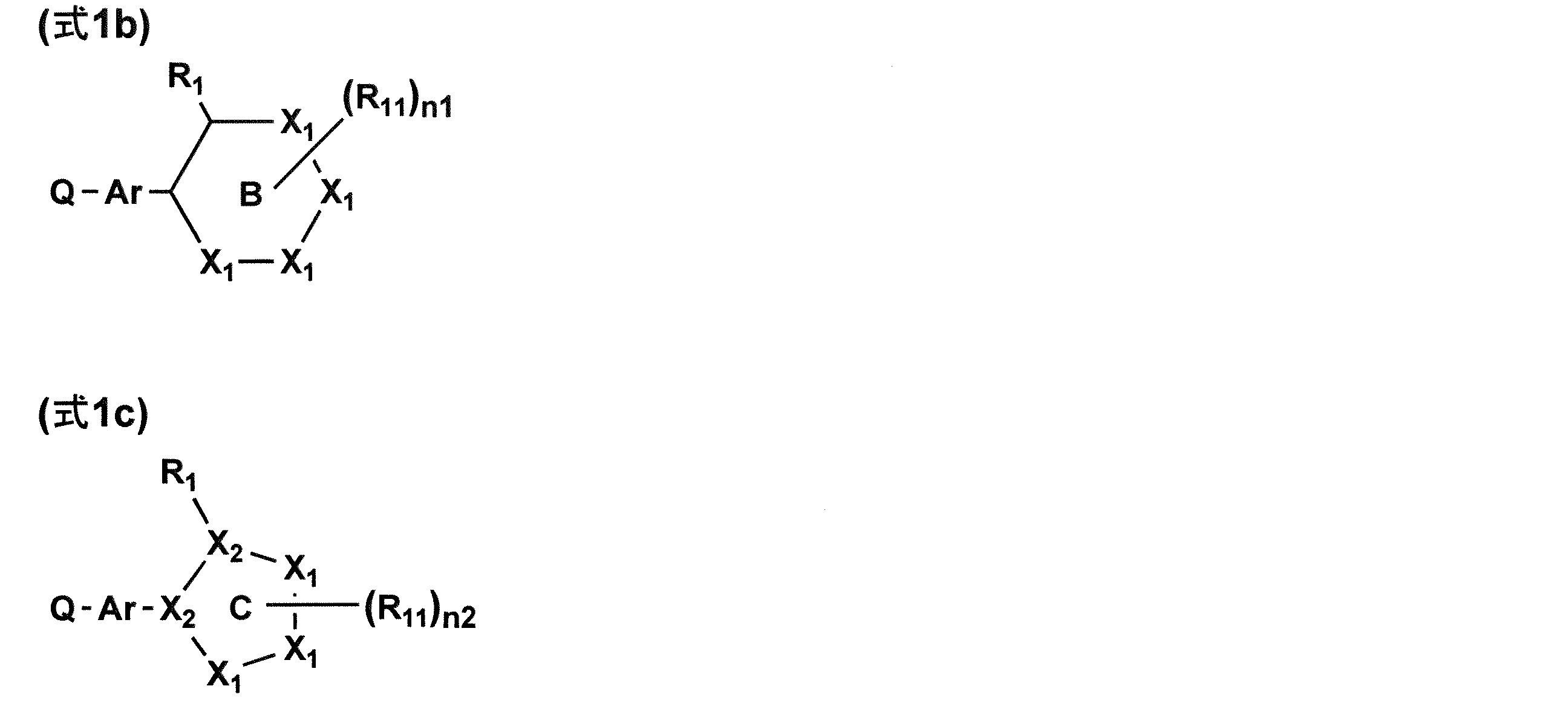
前記式(1a)で表される構造は、下記式(1b)又は式(1c)で表される構造であることが好ましい。
Arは、アリール環、ヘテロアリール環又はそれらの縮合環を表す。
環Bは、芳香族六員環を表す。
環Cは、芳香族五員環を表す。
X1は、それぞれ独立に、炭素原子、窒素原子、酸素原子及び硫黄原子から選ばれる原子を表す。
X2は、それぞれ独立に、炭素原子及び窒素原子から選ばれる原子を表す。
Q-Arは、赤外発光性残基を表す。
R1は、Arと環Bの二面角が45度以上となる基を表す。またR1は、Arと環Cの二面角が45度以上となる基を表す。
R11は、置換基を表し、隣接するR1と、又は複数のR11同士が環を形成していてもよい。
n1は、0~4の整数を表す。n2は、0~3の整数を表す。)
環Bは、芳香族六員環を表す。具体的には、式(1a)で挙げた、アリール環、ヘテロアリール環のうちで六員環の基を表す。
環Cは、芳香族五員環を表す。具体的には、式(1a)で挙げた、ヘテロアリール環のうちで五員環の基を表す。
X2は、それぞれ独立に、炭素原子及び窒素原子から選ばれる原子を表す。
R11は、置換基を表し、隣接するR1と、又は複数のR11同士が環を形成していてもよい。
R11が表す置換基としては、R1と同様のものが挙げられ、同様のものが好ましい。
n1は、0~4の整数を表す。n2は、0~3の整数を表す。
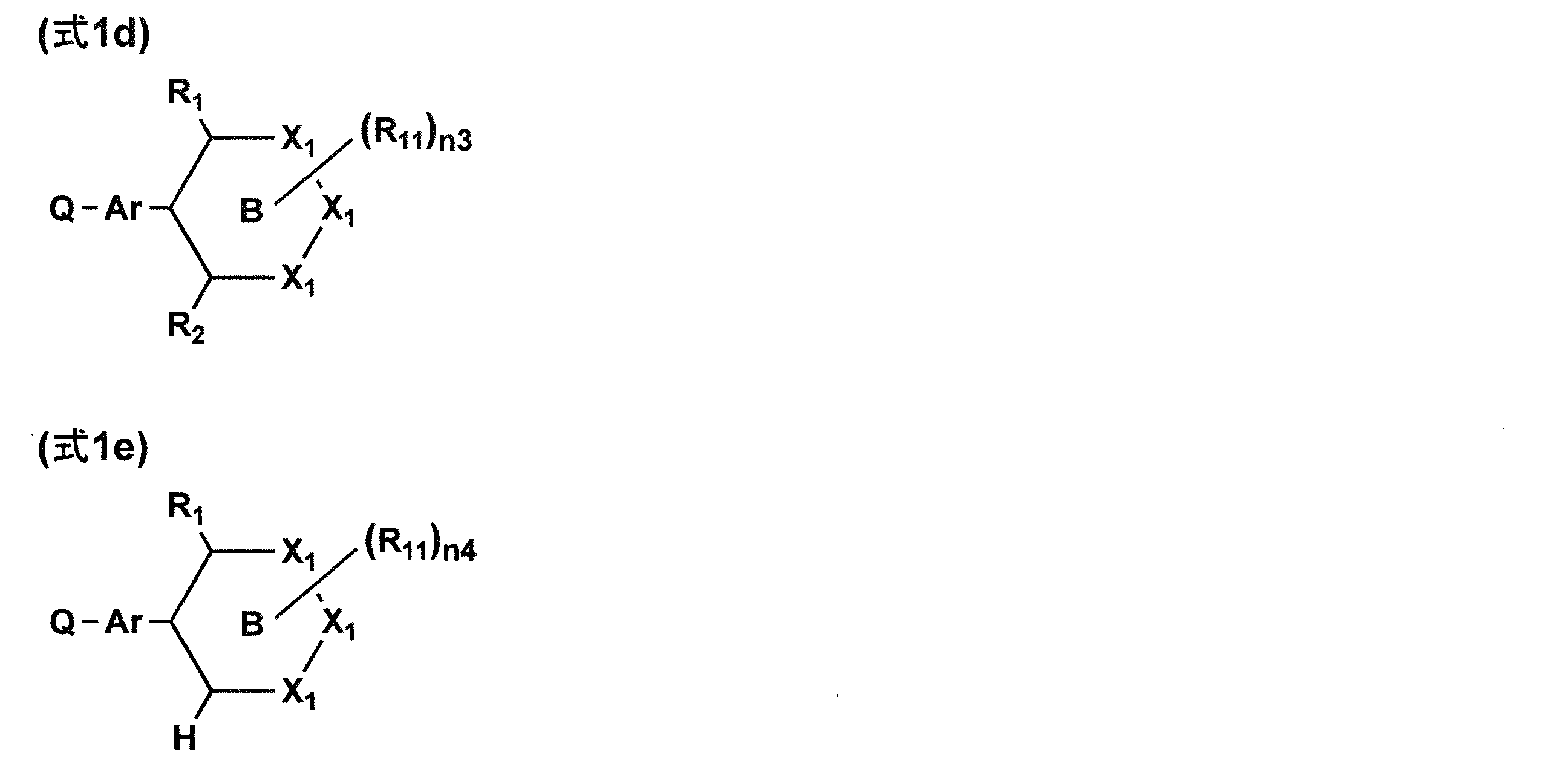
前記式(1a)で表される構造は、下記式(1d)又は式(1e)で表される構造であることが好ましい。

Arは、アリール環、ヘテロアリール環又はそれらの縮合環を表す。
環Bは、芳香族六員環を表す。
X1は、それぞれ独立に、炭素原子、窒素原子、酸素原子及び硫黄原子から選ばれる原子を表す。
Q-Arは、赤外発光性残基を表す。
R1は、Arと環Bの二面角が45度以上となる基を表す。
R2及びR11は、それぞれ独立に、置換基を表し、R11と隣接するR1若しくはR2と、又は複数のR11同士が環を形成していてもよい。
n3及びn4は、それぞれ独立に、0~3の整数を表す。)
Ar、環B、X1、Q-Ar、R1及びR11は、式(1b)及び式(1c)で述べたAr、環B、X1、Q-Ar、R1及びR11と同義である。
R2は、置換基を表す。置換基としては、R11で述べた置換基を適用することができるが、アルキル基、アルコキシ基、アミノ基、アリール基、ヘテロアリール基、フェノキシ基、アルキルチオ基、カルボニル基又はカルボキシ基を表すこととが好ましい。
n3及びn4は、それぞれ0~3の整数を表す。
式(1a)で表される構造を有する化合物が、下記一般式(2a)、(3a)、(4a)、(5a)、(6a)、(7a)又は(8a)で表される構造を有する化合物であることが好ましい。

環D及び環Eは、それぞれ独立に、ヒドロキシ基、アルコキシ基、NHCORa(Raは炭化水素基を表す。)基、NHSO2Rb(Rbは炭化水素基を表す。)基又はNHPO(ORf)(ORg)(Rf及びRgは、それぞれ独立に、炭化水素基を表す。)基で置換されていてもよいアリール環を表す。
環F及び環Gは、それぞれ独立に、アリール環を表す。
L1~L4は、それぞれ独立に、アリール環、ヘテロアリール環又は単結合を表す。X3は、アリール基で置換されていてもよい炭素原子又は窒素原子を表す。
R3及びR4は、それぞれ独立に、スルホ基で置換されていてもよいアルキル基を表す。R5及びR7は、それぞれ独立に、水素原子又はアルキル基を表す。
R6は、水素原子又はアリール基を表し、R5又はR7がアルキル基を表すとき、R5又はR7と連結してシクロアルケン環を形成してもよい。
INDで表される部分がカチオン部である場合、X4は対アニオンを表し、pは電荷を中和するために必要な数を表し、式中のINDで表される部分がアニオン部である場合、X4は対カチオンを表し、pは電荷を中和するために必要な数を表し、式中のINDで表される部位の電荷が分子内で中和されている場合、pは0である。
Ar1及びAr2は、6員環からなるアリール基又は5員環若しくは6員環からなるヘテロアリール基を表し、これらの基は2個以上の環からなっていてもよい。
Xa及びXbは、それぞれ独立に、窒素原子又はCR5を表し、R5は、水素原子又は電子吸引基を表す。
R1~R4は、それぞれ独立に、シアノ基、ハロゲン、置換されていてもよいアルキル基、置換されていてもよいアルコキシ基、置換されていてもよいアルキニル基、置換されていてもよいアリール基又は置換されていてもよいヘテロアリール基を表す。
Ar3及びAr4は6員環からなるアリール基又は5員環若しくは6員環からなるヘテロアリール基を表し、これらの基は2個以上の環からなっていてもよい。
環Aは、それぞれ独立に、アリール環、ヘテロアリール環又はそれらの縮合環を表す。
R1は、それぞれ環Aが結合しているピロール環(一般式(7a))又はベンゼン環(一般式(8a))との二面角が45度以上となる基を表す。
太線は、単結合又は二重結合を表す。
Zは、下記式(Z)又は置換基を表し、少なくとも一つは、式(Z)を表す。
n5は、1~4の整数を表す。n6は、1~4の整数を表す。)

*は、式(1a)の発光性残基中のArとの結合部位を表す。
R1は、Arと環Aの二面角が45度以上となる基を表す。
太線は、単結合又は二重結合を表す。)
環F及び環Gは、それぞれ独立に、アリール環を表す。
L1~L4は、それぞれ独立に、アリール環、ヘテロアリール環又は単結合を表す。以上の環D~Gで表されるアリール環、及びL1~L4はで表されるアリール環とヘテロアリール環は、式(1a)で述べたアリール環、又はヘテロアリール環のものを用いることができる。
X3は、アリール基で置換されていてもよい炭素原子又は窒素原子を表す。
R3及びR4は、それぞれ独立に、スルホ基で置換されていてもよいアルキル基を表す。R5及びR7は、それぞれ独立に、水素原子又はアルキル基を表す。
R6は水素原子又はアリール基を表し、R5又はR7がアルキル基を表すとき、R5又はR7と連結してシクロアルケン環を形成してもよい。
n5は、1~4の整数を表す。n6は、1~4の整数を表す。
式(Z)中、Ar、環A、R1及び太線は、式(1a)のAr、環A、R1及び太線と同義である。
*は、式(1a)の発光性残基中のArとの結合部位を表す。
一般式(7a)において、R5が電子吸引基の場合、電子吸引基として、特に制限はないが、シアノ基が好ましい。
前記式(1a)で表される構造を有する化合物が下記一般式(2b)で表される構造を有するスクアリリウム化合物であることが好ましい。

R1a~R1d、R2a~R2d、R22~R24、R32~R34、R42~R44、R52~R54及びR63~R66は、それぞれ独立に、水素原子、アルキル基、アルコキシ基、フェノキシ基、アミノ基、アリール基又はヘテロアリール基を表すが、R1aとR2a、R1bとR2b、R1cとR2c、及びR1dとR2dの組み合わせの少なくとも一つは、ともに水素原子であることはない。
R1aはR22と、R2aはR24と、R1bはR32と、R2bはR34と、R1cはR42と、R2cはR44と、R1dはR52と、及びR2dはR54と環構造を形成していてもよい。
環H及び環Iは、それぞれ独立に、ヒドロキシ基、アルコキシ基、NHCORa(Raは炭化水素基を表す。)基、NHSO2Rb(Rbは炭化水素基を表す。)基又はNHPO(ORf)(ORg)(Rf及びRgは、それぞれ独立に、炭化水素基を表す。)基で置換されていてもよいアリール環を表す。)
また、一般式(2b)で表される構造を有するスクアリリウム化合物において、環Hと環Iは同一で、ヒドロキシ基を有するアリール基を表し、前記R22~R24、R32~R34、R42~R44及びR52~R54は、前記R1a~R1d及びR2a~R2dと同一又は水素原子を表すが、前記R1aとR2a、R1bとR2b、R1cとR2c、R1dとR2dの組み合わせの少なくとも一つは、ともに水素原子であることはなく、前記R22、R24、R32、R34、R42、R44、R52及びR54は、水素原子を表すことが好ましい。
さらに、環Hと環Iは同一で、ヒドロキシ基を有するアリール基を表し、前記R1aはR22と、R2aはR24と、R1bはR32と、R2bはR34と、R1cはR42と、R2cはR44と、R1dはR52と、R2dはR54と、それぞれ結合し、炭素鎖で5員環又は6員環構造を形成していることが好ましい。




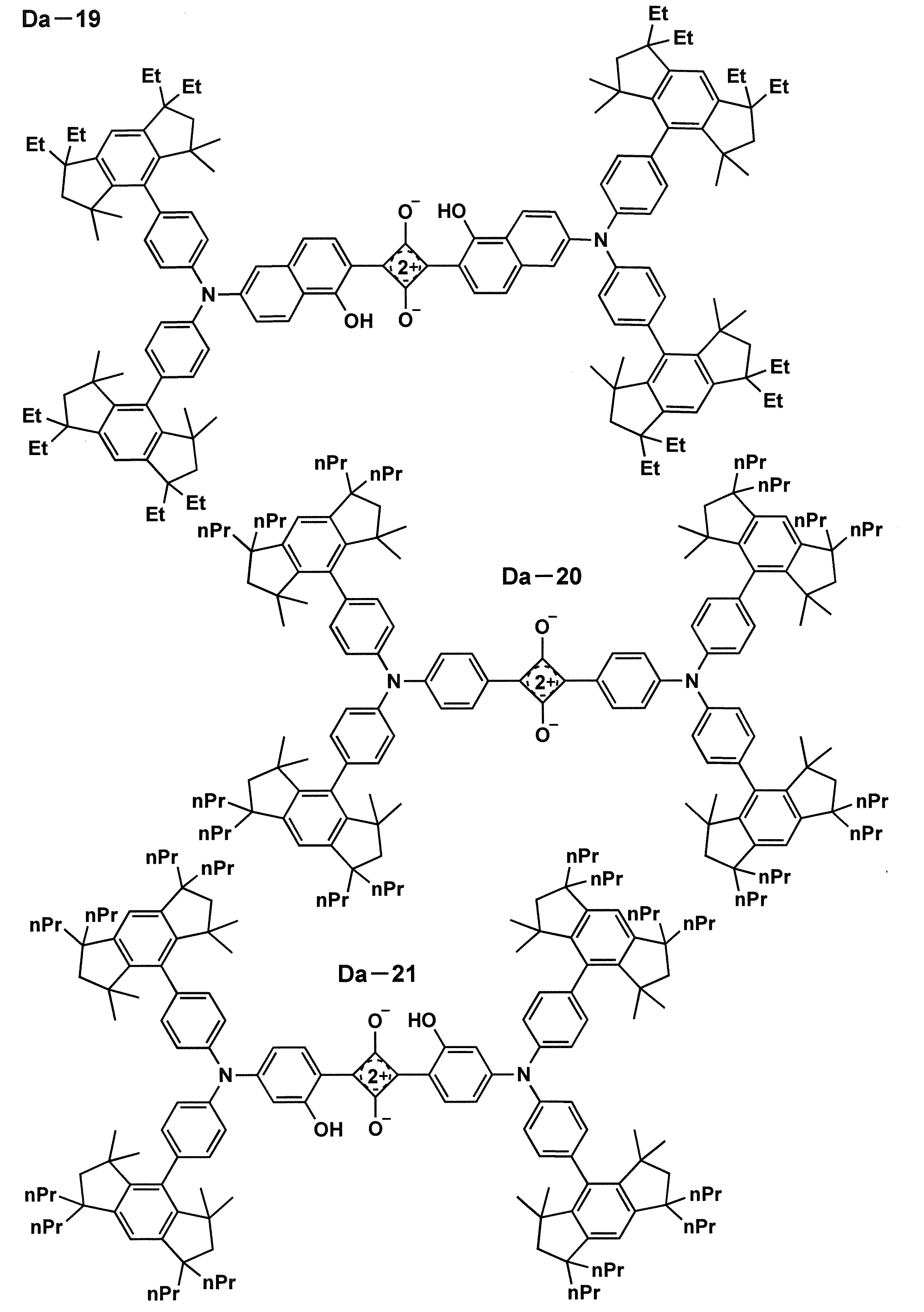
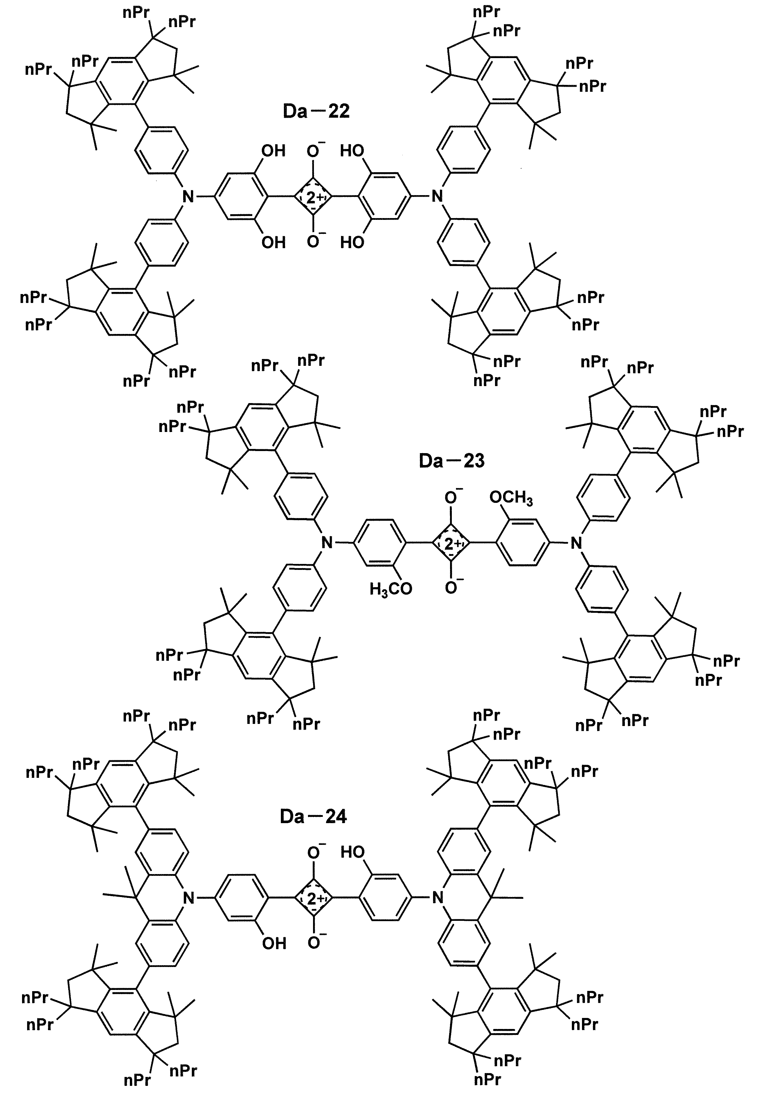
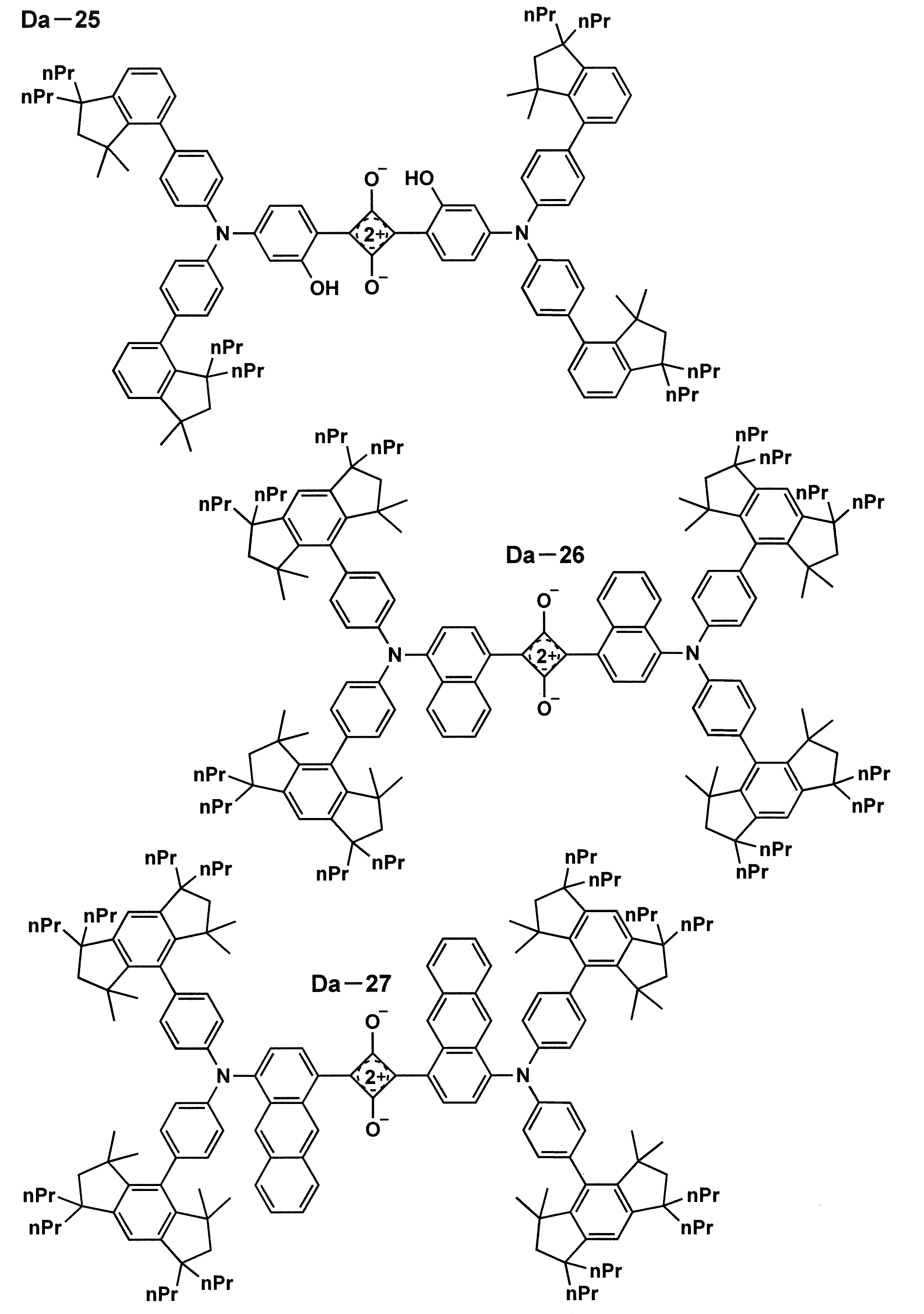
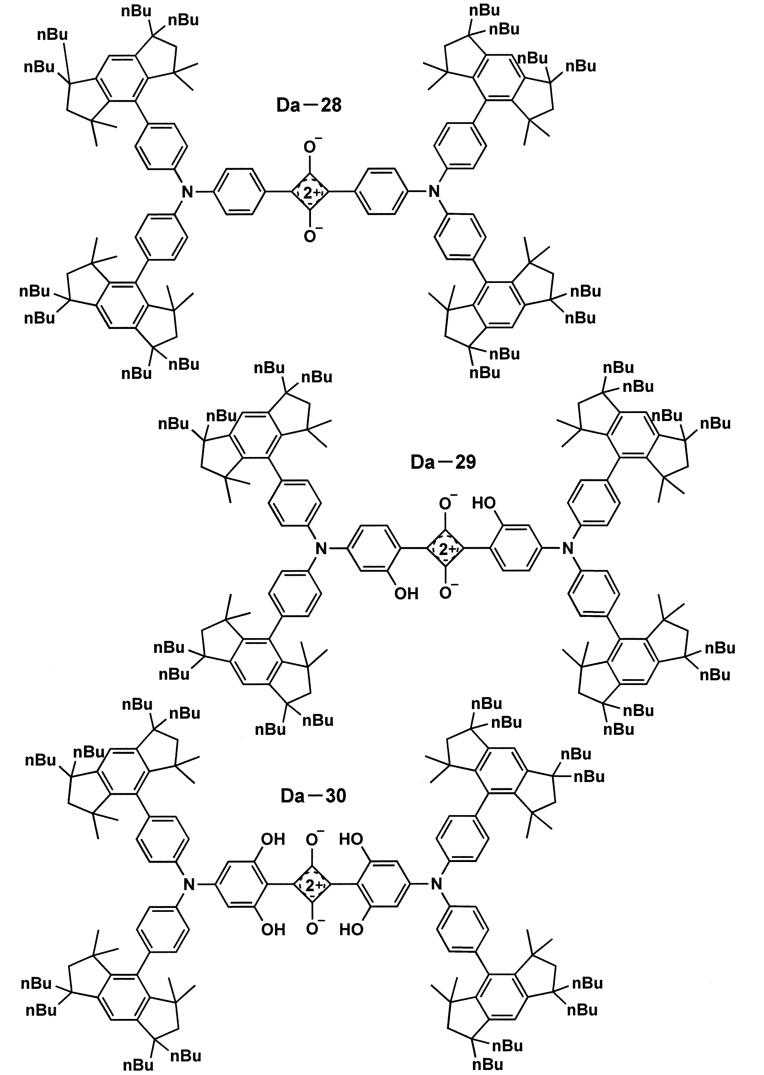




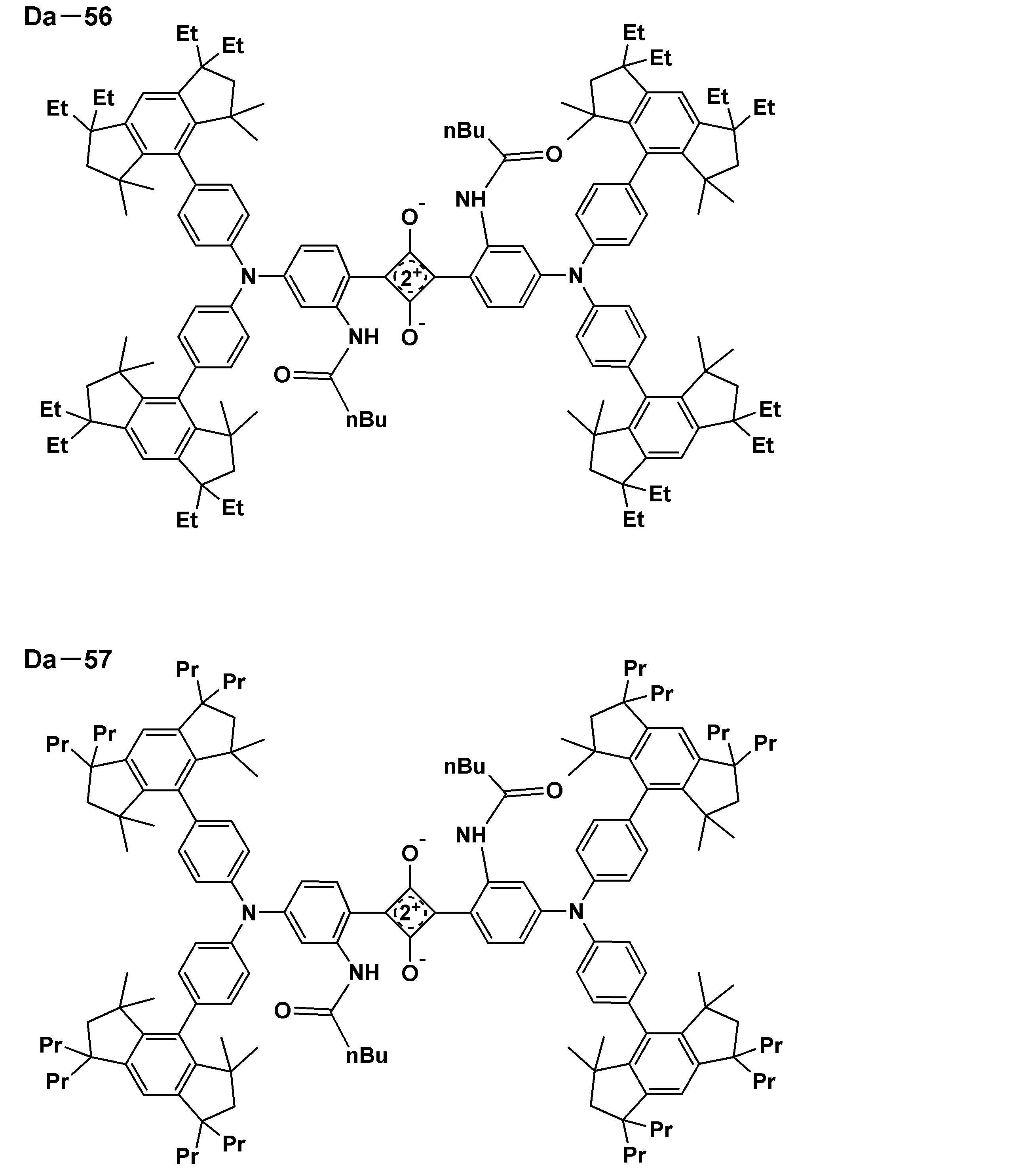
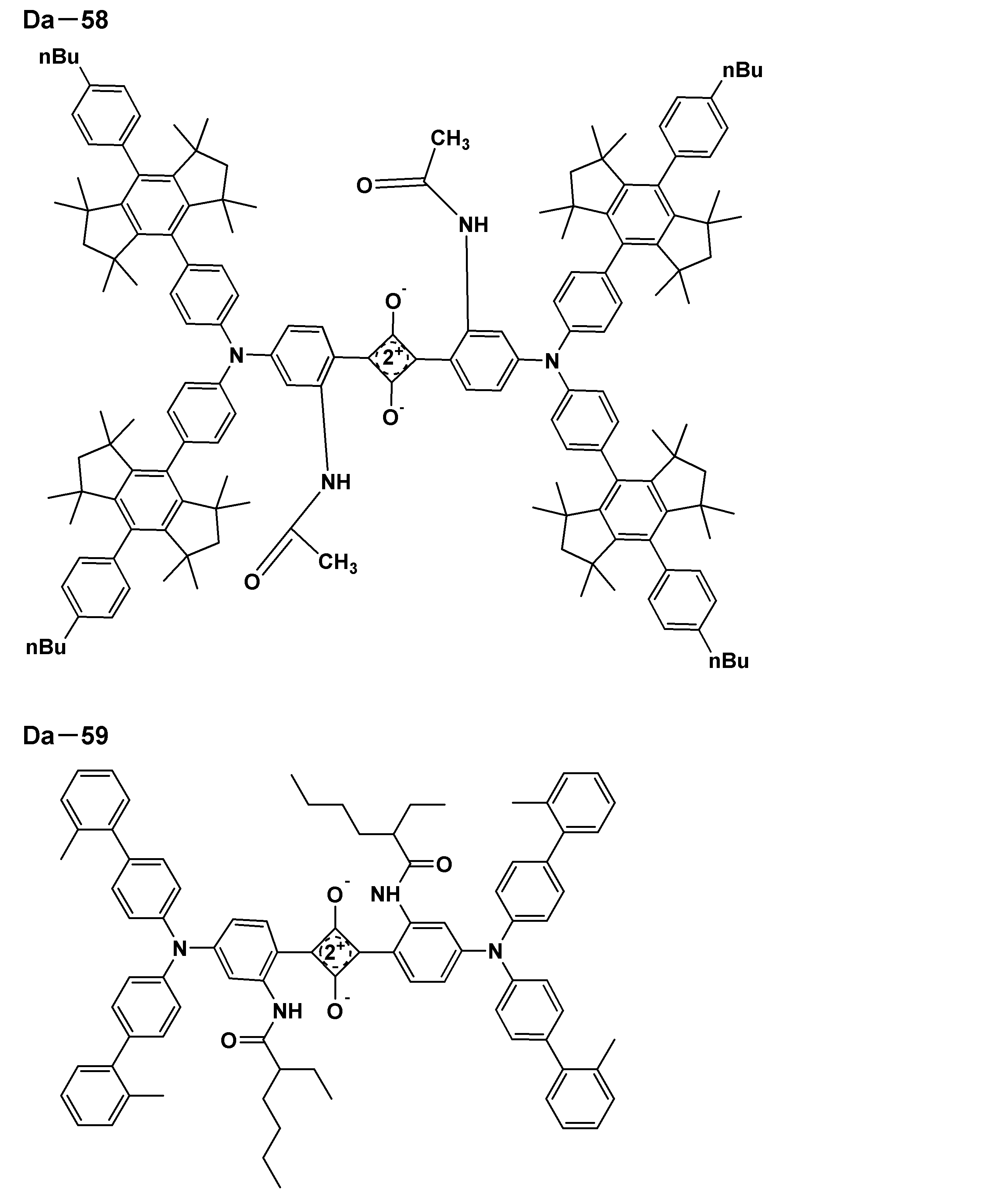
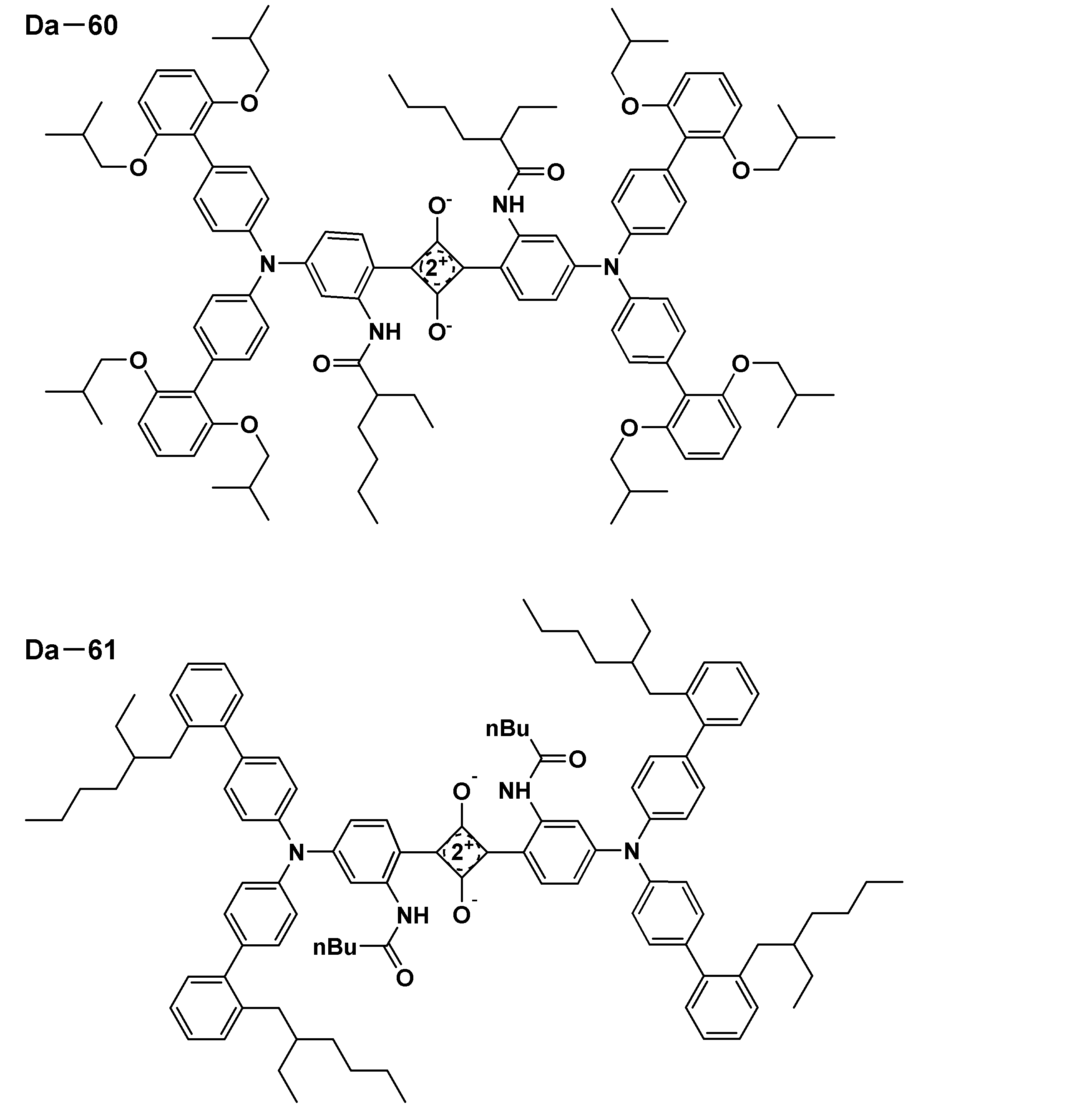

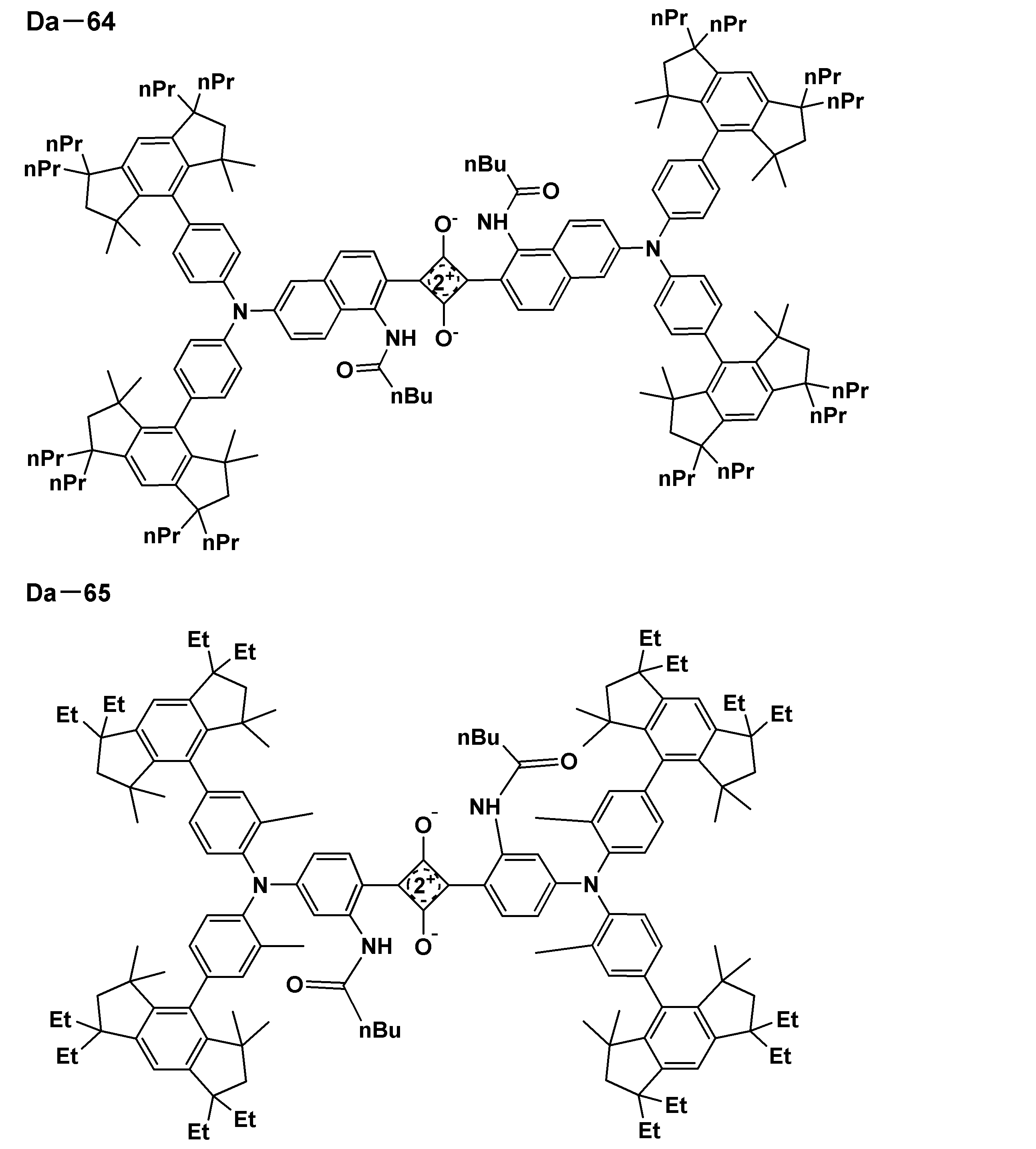


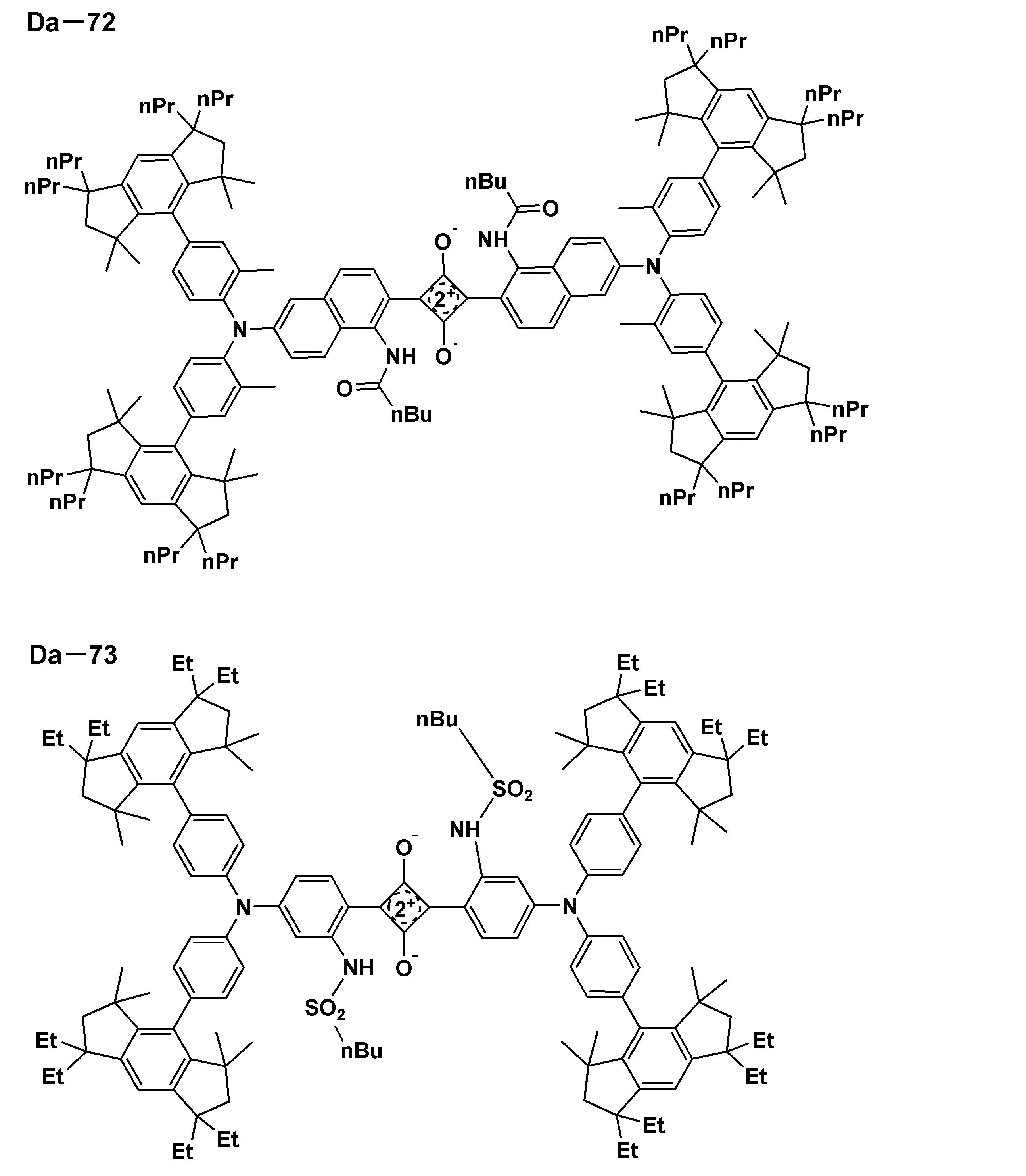
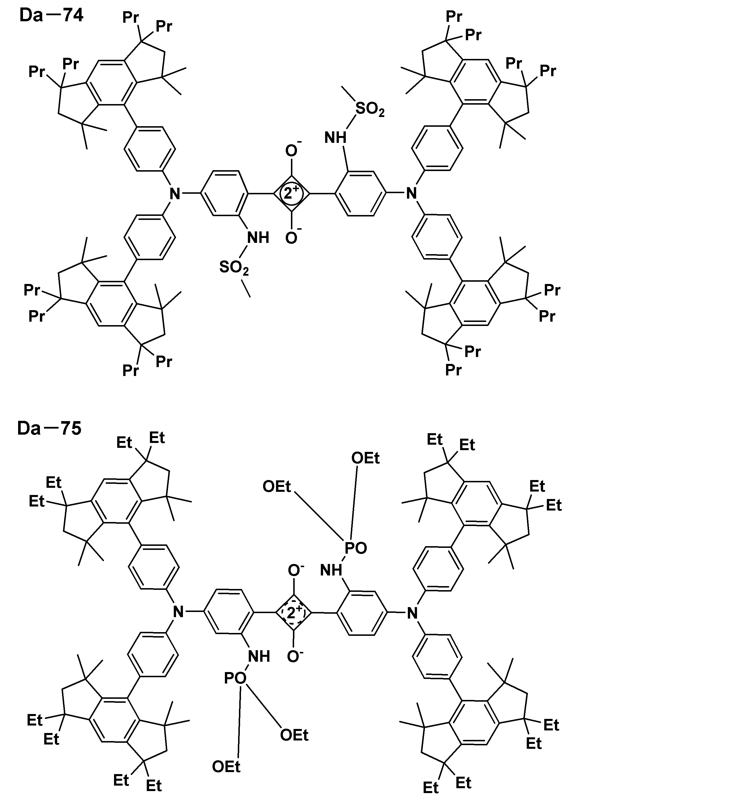

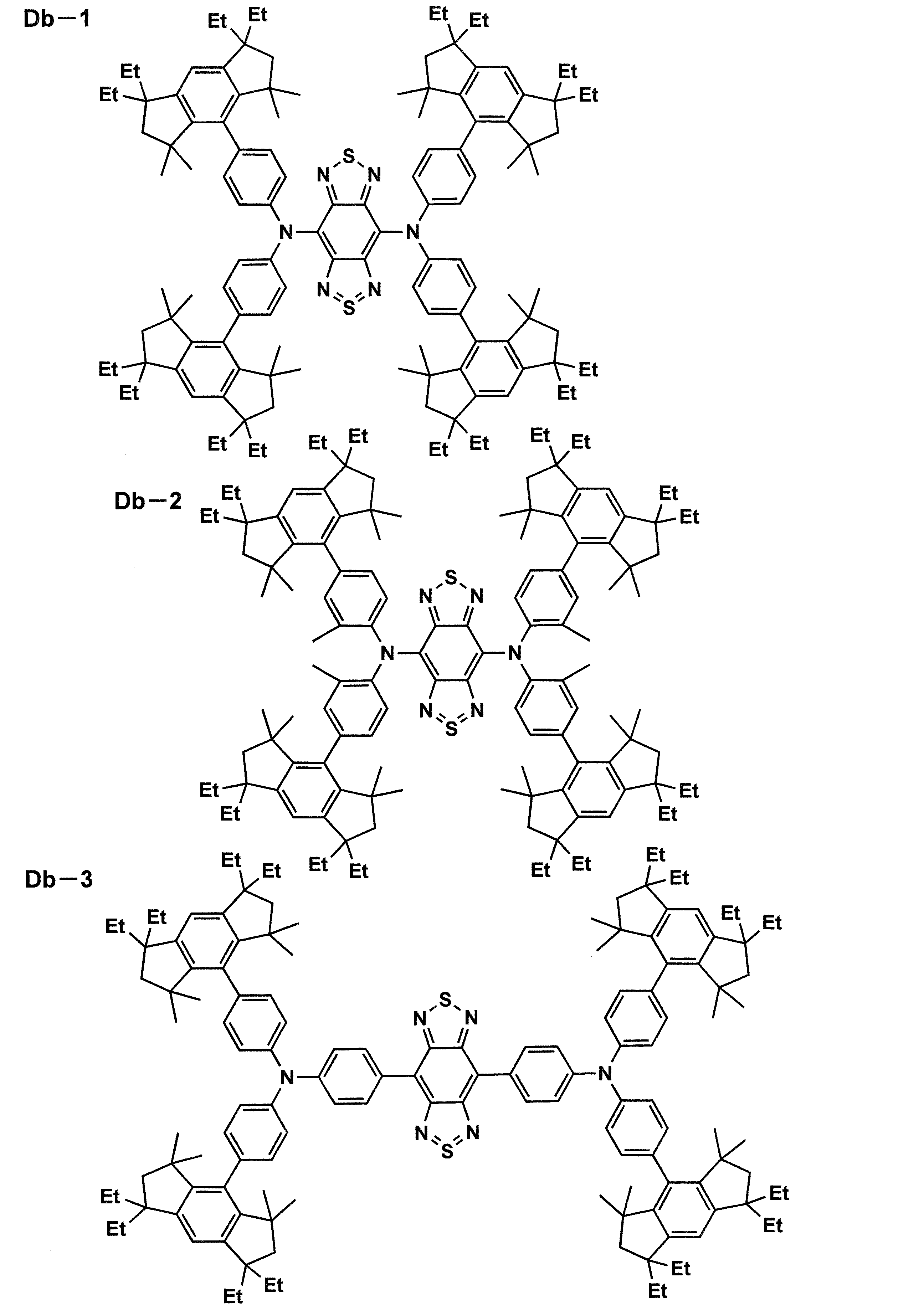
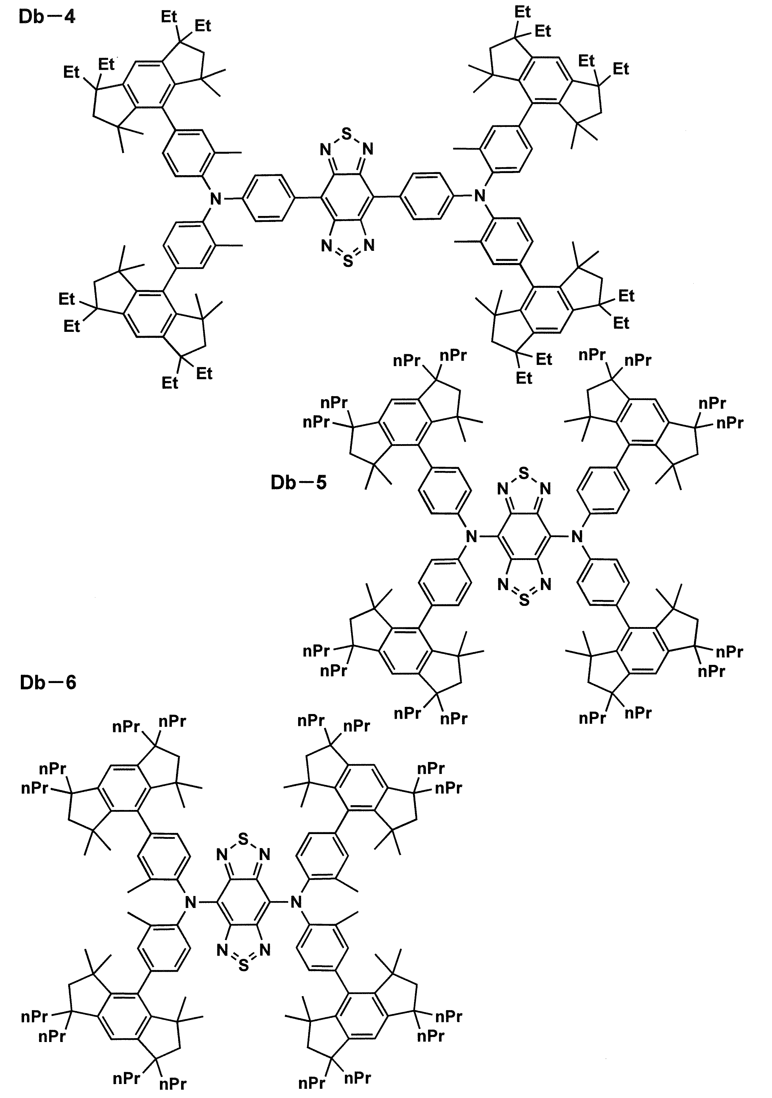


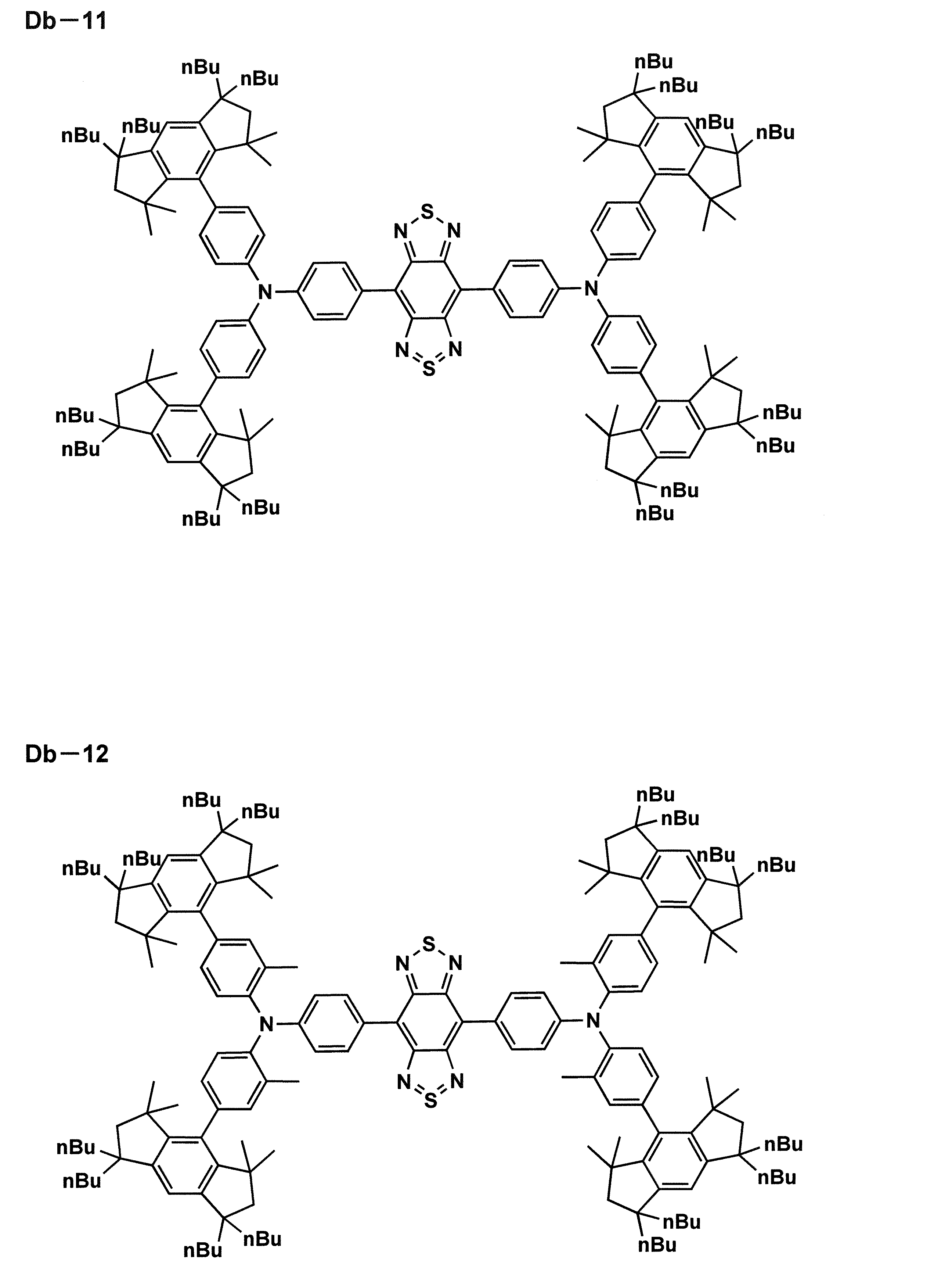


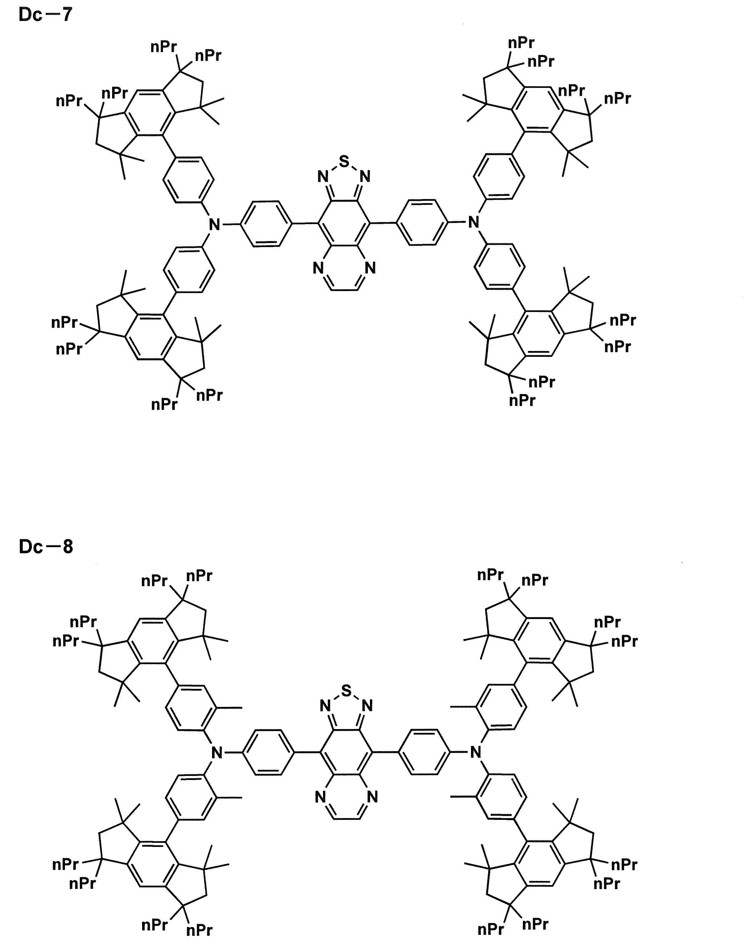
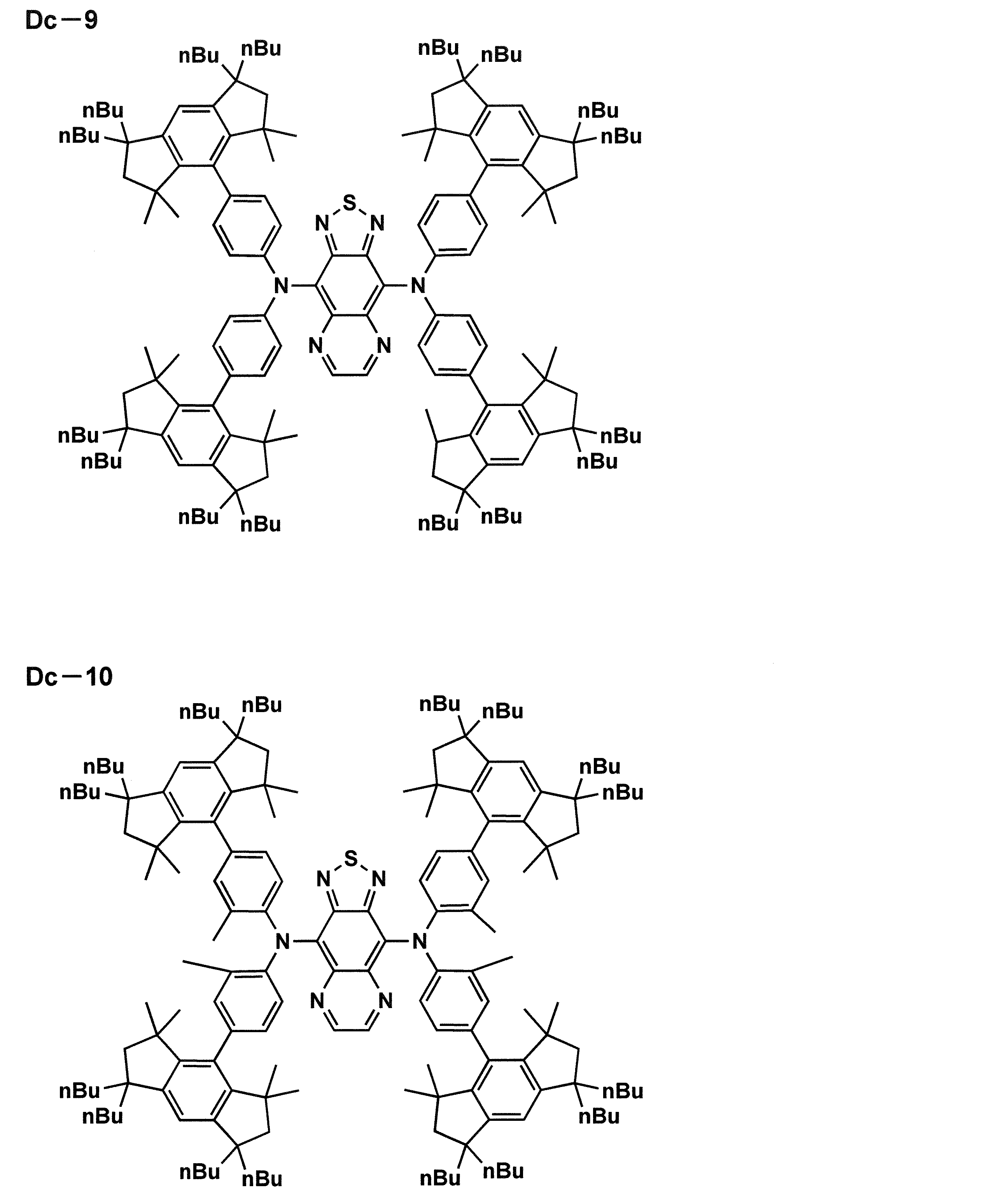
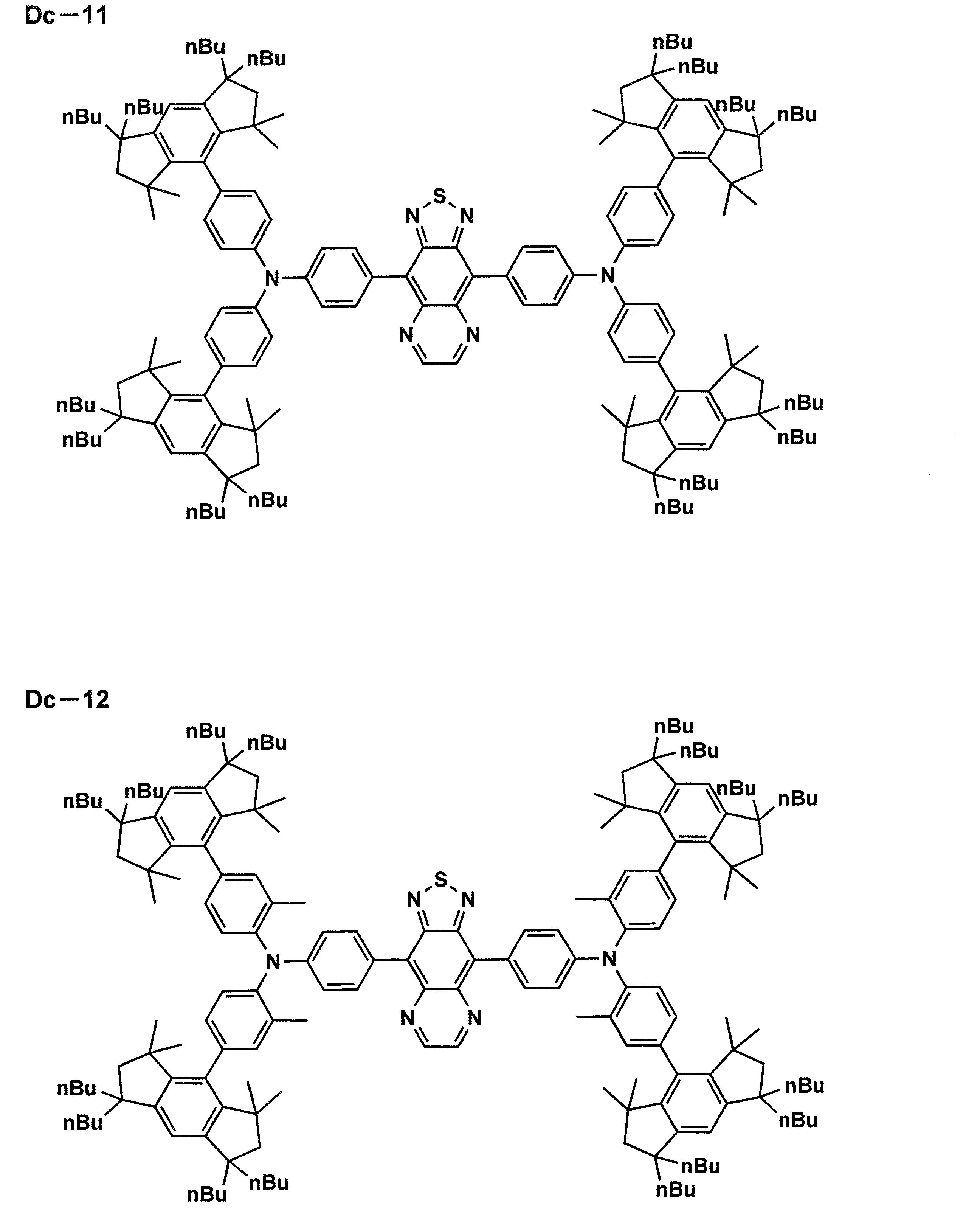


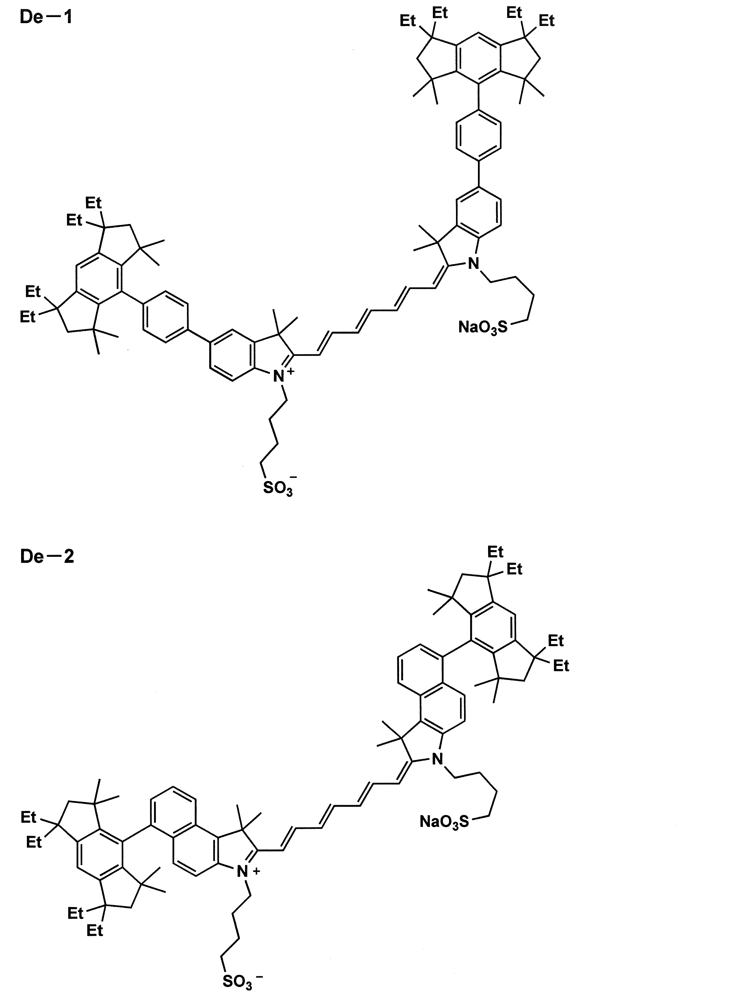
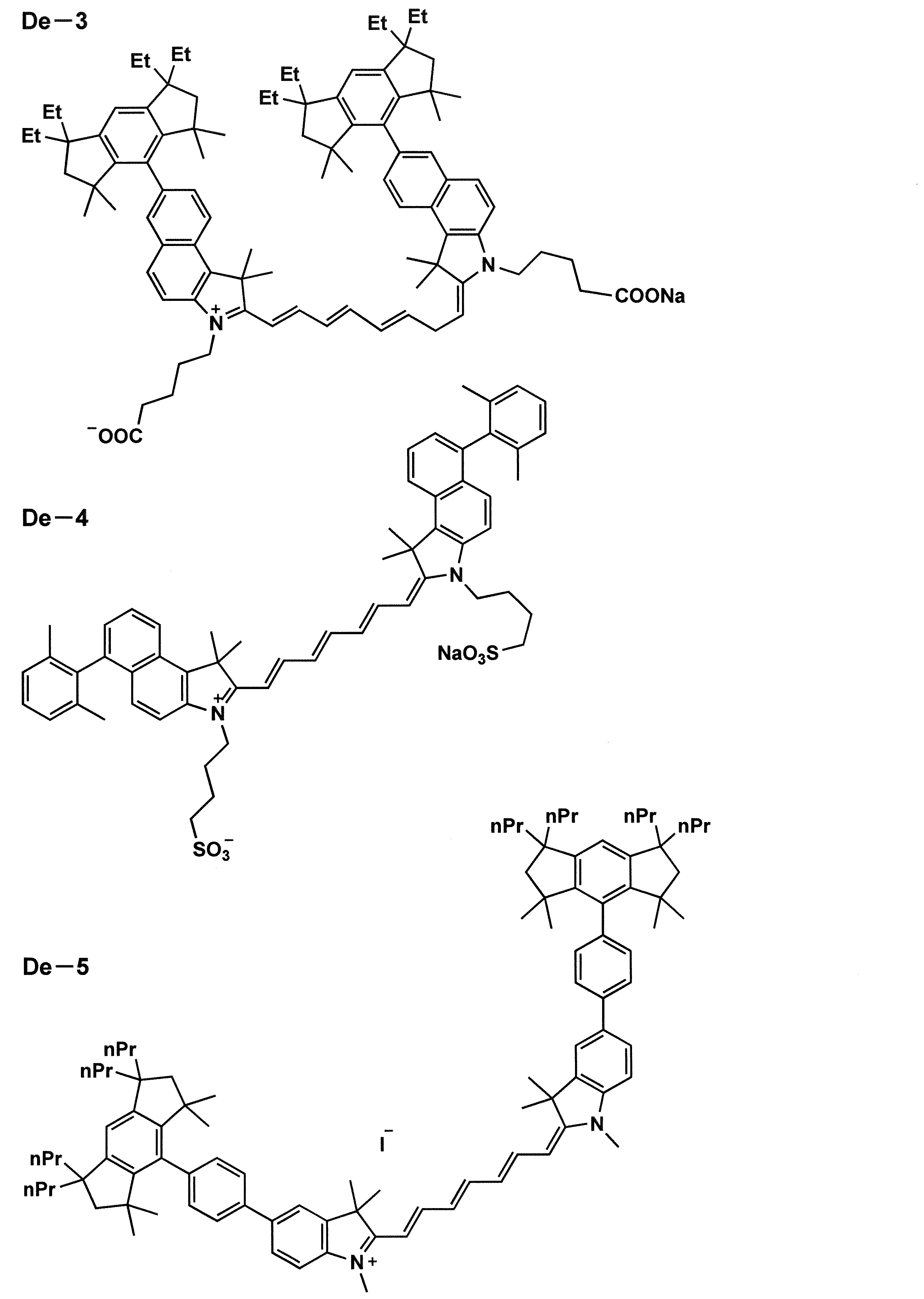
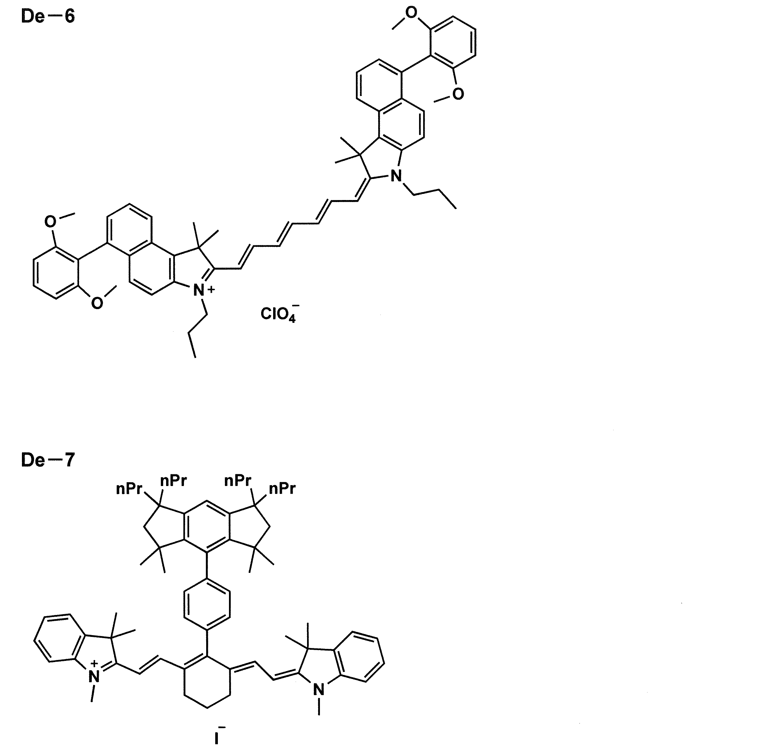


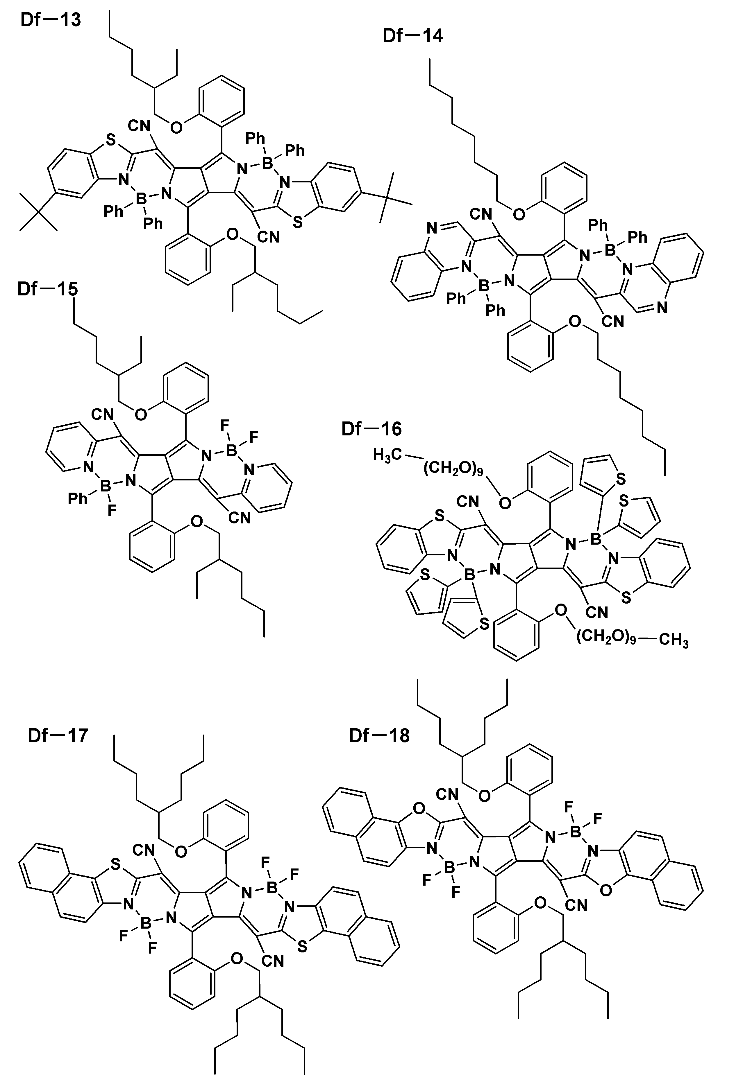


本発明に係る一般式(2a)で表されるスクアリリウム化合物は、例えば、Chemistry of Materials,第23巻、4789ページ(2011年)、The Journal of
Physical Chemistry,第91巻、5184ページ(1987年)に記載の方法、又は、これらの文献に記載の参照文献に記載の方法を参照することにより合成することができる。一例として、以下に例示化合物Da-2の合成例を示す。
下記スキームにより合成することができる。

測定装置:JNM-ECZ400S(400MHz,1H-NMR)
測定条件:24.6度、CDCl3溶媒使用、テトラメチルシラン基準(0ppm)
δ/ppm=0.81(48H,t,J=7Hz),0.97(48H,s),1.50-1.63(m,16H),1.60-1.72(m,16H),6.47-6.54(4H,m),6.68(4H,s),7.20(8H,d,J=8Hz),7.31(8H,d,J=8Hz),7.92(0.8H,d,J=9Hz),8.05(0.2H,d,J=9Hz),11.5(0.2H,s),12.2(0.8H,s)
Nature Materials vol 15,2016,p235-243
J. Phys. Chem.C 2009,113,p1589-1595
Materials 2013,6,p1779-1788
Molecules 2018,23,p226
Chem. Commun.,2010,46,p5289-5291
発光量子収率Φ(%)は、吸収された光子数と放出された光子数の割合で表される。励起された分子の全てが蛍光によって基底状態に戻れば、発光量子収率Φ(%)は100%となるが、無輻射失活が生じると100%とはならない。
励起状態にある分子の蛍光遷移と無輻射遷移の速度定数をそれぞれKfとKnrとおくと、発光量子収率Φ(%)は、
で表される。
本発明の赤外発光化合物は蛍光発光する化合物である。本発明の赤外発光化合物の蛍光スペクトルは、以下の方法で確認することができる。
本発明の赤外発光化合物は、長波長の発光と高い発光量子収率を示すことができる。このような性質を有することから、本発明の赤外発光化合物は、発光性薄膜、発光性粒子及び波長変換膜として用いることができる。例えば、新たなタイプの蛍光プローブ用色素として生物学及び医学における標識体として、バイオイメージに利用することができる。また、励起した電子が、基底状態へ戻る際に余分なエネルギーとして蛍光を放射する本発明の赤外発光化合物は、吸収と放出のエネルギーの違いから波長変換能を有しており、色変換フィルターとして、染料、顔料、光学フィルター、農業用フィルム等に用いることもできる。
本発明の発光性薄膜は、本発明の赤外発光化合物を含有することを特徴とする。本発明の発光性薄膜は、本発明の赤外発光化合物に、製膜安定性等のために分散剤を加えた組成物、又はこれにさらに溶媒を加えた組成物を薄膜状に形成することにより作製することができる。
本発明の発光性粒子は、本発明の赤外発光化合物を含有することを特徴とする。赤外発光化合物を粒子表面に吸着させた発光性粒子であっても、赤外発光化合物を内包した発光性粒子であってもよい。
本発明の波長変換膜は、本発明の赤外発光化合物を含有することを特徴とする。波長変換膜は赤外発光する赤外発光面光源に適用することができる。
本発明の赤外発光面光源は、波長変換膜を具備することを特徴とする。本発明の赤外発光面光源は、赤外光を発光する発光部材であって、近赤光領域を含む可視光領域(380~1000nm)、好ましくは近赤光領域を含む緑~赤色領域(495~900nm)、特に好ましくは近赤光領域を含む赤色領域(600~850nm)の範囲内の光を発光する有機EL素子、マイクロLED、又は拡散板と組み合わせたLEDなどの面光源の光を吸収して、近赤外光、例えば、700nmを超え、1500nm以下の領域で発光することが好ましい。
本発明の波長変換膜を具備する赤外発光面光源は、生体計測装置、生体認証装置に好適に用いられる。
<二面角>
以下の実施例で用いた本発明の赤外発光化合物13種、比較用化合物R-4~R-6の各々について、二面角を分子軌道計算用ソフトウェアとしてGaussian社製Gaussian09を用いて前述した条件で計算して求めた。結果を表Iに示す。本発明に係る置換基を有しない化合物の場合は「-」と記した。

表Iに示した本発明の赤外発光化合物13種及び比較用化合物R-4~R-6の各々について、溶液中での発光波長及び発光量子収率を、それぞれ以下の方法で評価した。
本発明の赤外発光化合物をトルエン溶液中で10-6Mに調整し、常温(300K)でこの試料の発光波長(蛍光スペクトル)を測定した。発光波長の測定には、分光蛍光光度計(日立ハイテクノス社製、F7000)を用いた。また、この溶液の発光量子収率を、絶対PL量子収率測定装置(浜松ホトニクス社製:C11347)を用いて測定した。
発光波長に関しては、以下の基準で評価した。
ΔPL(λmax)を以下で定義し、
ΔPL(λmax)[nm]=(該当する化合物の発光極大波長)-(化合物R-6の発光極大波長)
発光量子収率は、R-6の発光量子収率を1.0としたときの相対発光量子収率を用いた。測定結果を図3に示す。
図3は、比較化合物R-6に対する、ΔPLと相対発光量子収率を示すグラフである。
(2)-1本発明の発光性薄膜の評価
マトリックス材料であるポリスチレン(ACROS ORGANICS社製、重量平均分子量Mw=260000)と比較化合物のR-4を、トルエン中に質量比で99:1となるように添加し、これらをナスフラスコに入れて80℃に加熱撹拌して十分に溶解させた。

比較化合物のR-4を比較化合物のR-7に変えた以外は(2)-1に記載の比較の発光性薄膜と同様にして、比較化合物のR-7を含有する発光性薄膜を作製した。更に、比較のR-7を本発明の赤外発光化合物Da-50とDa-51に変えた以外は同様にして、それぞれ本発明の発光性薄膜膜を作製した。(2)-1と同様にこれらの試料の発光波長(蛍光スペクトル)及び発光量子収率を測定した。それぞれの発光性薄膜のトルエン溶液中での発光量子収率を1.00としたときのこれらの発光性薄膜の発光量子収率の相対値を以下に示す。
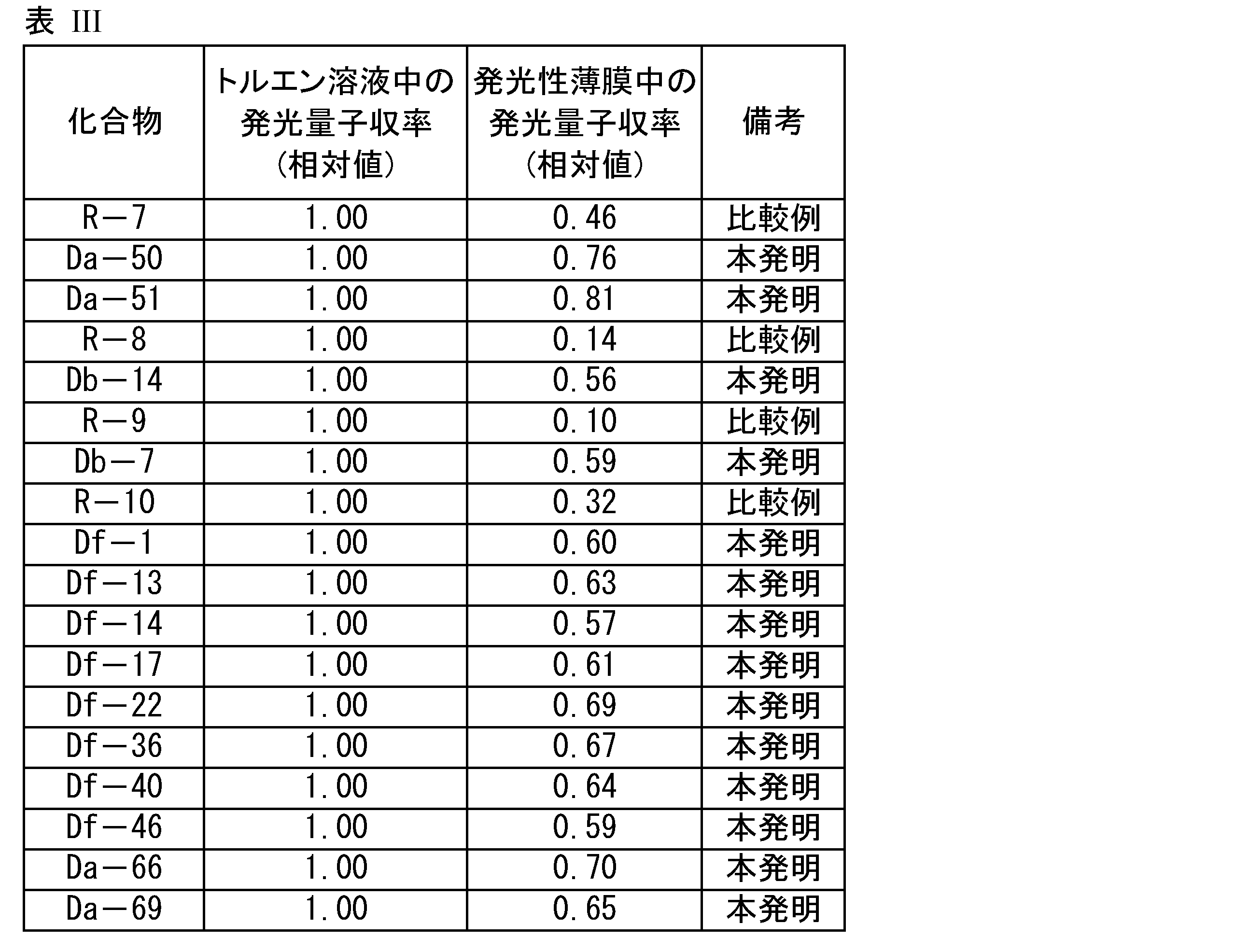
比較の化合物R-8~R-10と本発明の赤外発光化合物を用いた発光性薄膜との比較でも、同様の結果が得られた。
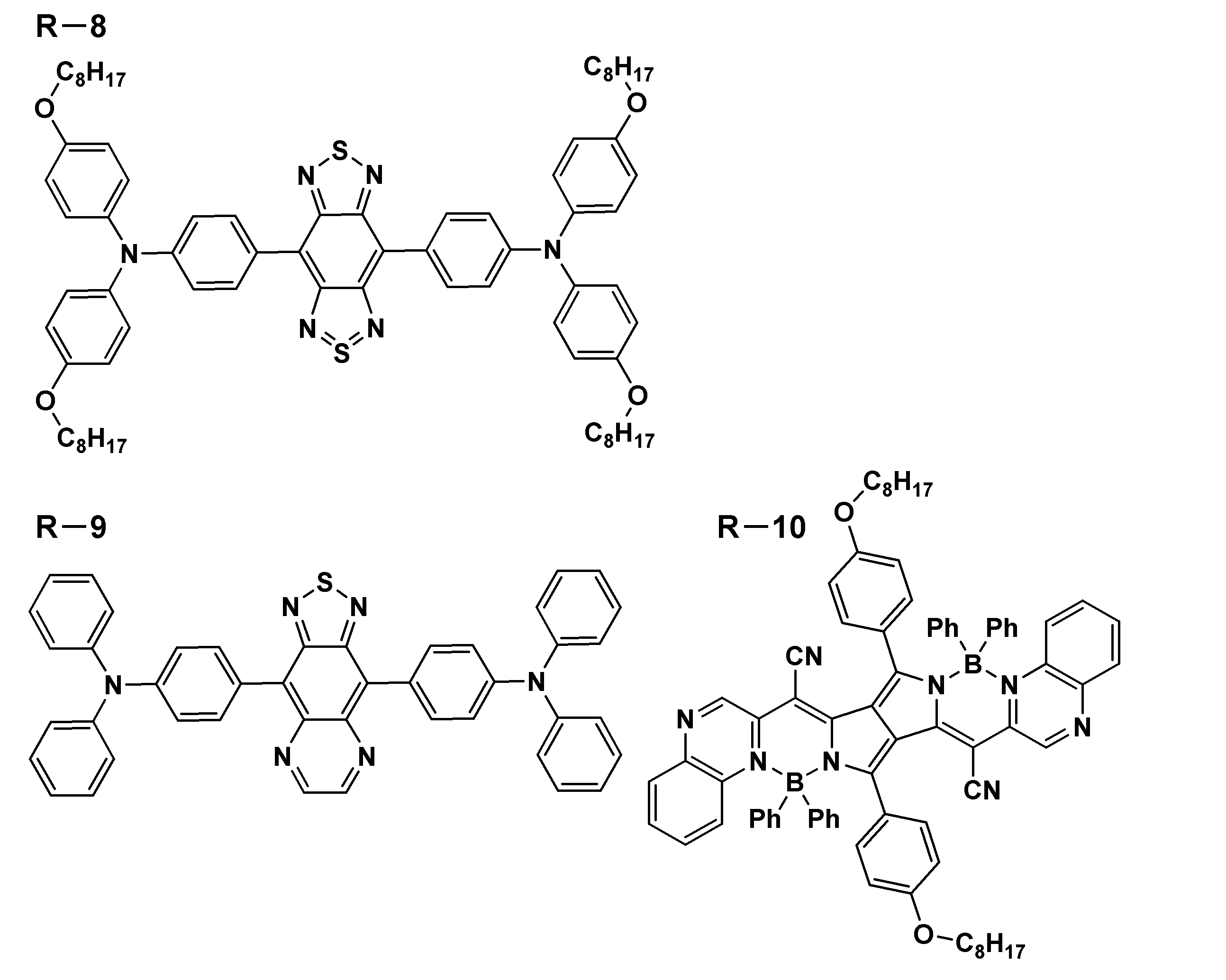
R-8:Chem.Mater vol20,2008,6208
R-9:J.Phys.Chem.C, 2009,113,1589
R-10:Chem.Eur.J.2009,15,4857
<発光性粒子>
本発明の赤外発光化合物と比較化合物について、発光性粒子中での発光量子収率を測定した。
ポリスチレン(PS)粒子分散液(固形分5.2質量%、ポリスチレン粒子の体積平均粒子径0.12μm、分散媒:水)96μLに、水100μL、非イオン性界面活性剤(Kolliphor P407:シグマアルドリッチ製)の2%水溶液50μL、表IVに示した各化合物の0.01mmol/L THF溶液100μLを加え、ポリスチレン粒子と各化合物との混合液を調製した。この混合液を25℃で2分撹拌することでポリスチレン粒子を作製した。
前項で得られたポリスチレン粒子を含む発光性粒子分散液1~6の絶対蛍光量子収率を、蛍光量子収率測定装置(浜松ホトニクス製C11347-01)を用い測定した。それぞれ、本発明のDa-21を含む分散液No4の蛍光量子収率を1.0としたときの相対値を発光量子収率として評価した。
以上の結果を表IVに示す。

<波長変換膜>
[波長変換膜の作製]
(波長変換膜3の作製)
下記の方法に従って、図2に記載の構成からなる波長変換膜3を作製した。
赤色発光(R)する面光源である有機EL素子の発光面と、波長変換膜3とを密着させることにより、図1で示す構成の赤外発光面光源1を作製した。
2 可視光発光する面光源
3 波長変換膜
4A、4B ガスバリアーフィルム
5 発光色素層
6 接着剤層
IR 近赤外光
R 赤色発光
Claims (16)
- 下記式(1a)で表される構造を有することを特徴とする赤外発光化合物。

Ar及び環Aは、それぞれ独立に、アリール環、ヘテロアリール環又はそれらの縮合環を表す。
Q-Arは、赤外発光性残基を表す。
R1は、Arと環Aの二面角が45度以上となる基を表す。
太線は、単結合又は二重結合を表す。) - 前記式(1a)で表される構造が、下記式(1b)又は式(1c)で表される構造であることを特徴とする請求項1に記載の赤外発光化合物。
Arは、アリール環、ヘテロアリール環又はそれらの縮合環を表す。
環Bは、芳香族六員環を表す。
環Cは、芳香族五員環を表す。
X1は、それぞれ独立に、炭素原子、窒素原子、酸素原子及び硫黄原子から選ばれる原子を表す。
X2は、それぞれ独立に、炭素原子及び窒素原子から選ばれる原子を表す。
Q-Arは、赤外発光性残基を表す。
R1は、Arと環Bの二面角が45度以上となる基を表す。またR1は、Arと環Cの二面角が45度以上となる基を表す。
R11は、置換基を表し、隣接するR1と、又は複数のR11同士が環を形成していてもよい。
n1は、0~4の整数を表す。n2は、0~3の整数を表す。) - 前記式(1a)で表される構造が、下記式(1d)又は式(1e)で表される構造であることを特徴とする請求項1に記載の赤外発光化合物。
Arは、アリール環、ヘテロアリール環又はそれらの縮合環を表す。
環Bは、芳香族六員環を表す。
X1は、それぞれ独立に、炭素原子、窒素原子、酸素原子及び硫黄原子から選ばれる原子を表す。
Q-Arは、赤外発光性残基を表す。
R1は、Arと環Bの二面角が45度以上となる基を表す。
R2及びR11は、それぞれ独立に、置換基を表し、R11と隣接するR1若しくはR2と、又は複数のR11同士が環を形成していてもよい。
n3及びn4は、それぞれ独立に、0~3の整数を表す。) - 前記R1が、アルキル基、アルコキシ基、アミノ基、アリール基、ヘテロアリール基、フェノキシ基、アルキルチオ基、カルボニル基又はカルボキシ基を表すことを特徴とする請求項1から請求項3までのいずれか一項に記載の赤外発光化合物。
- 前記R11が、それぞれ独立に、アルキル基、アルコキシ基、アミノ基、アリール基、ヘテロアリール基、フェノキシ基、アルキルチオ基、カルボニル基又はカルボキシ基を表すことを特徴とする請求項2又は請求項3に記載の赤外発光化合物。
- 前記R2が、アルキル基、アルコキシ基、アミノ基、アリール基、ヘテロアリール基、フェノキシ基、アルキルチオ基、カルボニル基又はカルボキシ基を表すことを特徴とする請求項3に記載の赤外発光化合物。
- 前記Q-Arで表される赤外発光性残基が、スクアリリウム色素、ベンゾビスチアジアゾールを含む色素、チアジアゾロキノキサリンを含む色素、ピロメテン色素又はシアニン色素の残基であることを特徴とする、請求項1から請求項3までのいずれか一項に記載の赤外発光化合物。
- 前記式(1a)で表される構造を有する化合物が、下記一般式(2a)、(3a)、(4a)、(5a)、(6a)、(7a)又は(8a)で表される構造を有する化合物であることを特徴とする、請求項1に記載の赤外発光化合物。

環D及び環Eは、それぞれ独立に、ヒドロキシ基、アルコキシ基、NHCORa(Raは炭化水素基を表す。)基、NHSO2Rb(Rbは炭化水素基を表す。)基又はNHPO(ORf)(ORg)(Rf及びRgは、それぞれ独立に、炭化水素基を表す。)基で置換されていてもよいアリール環を表す。
環F及び環Gは、それぞれ独立に、アリール環を表す。
L1~L4は、それぞれ独立に、アリール環、ヘテロアリール環又は単結合を表す。X3は、アリール基で置換されていてもよい炭素原子又は窒素原子を表す。
R3及びR4は、それぞれ独立に、スルホ基で置換されていてもよいアルキル基を表す。R5及びR7は、それぞれ独立に、水素原子又はアルキル基を表す。
R6は、水素原子又はアリール基を表し、R5又はR7がアルキル基を表すとき、R5又はR7と連結してシクロアルケン環を形成してもよい。
INDで表される部分がカチオン部である場合、X4は対アニオンを表し、pは電荷を中和するために必要な数を表し、式中のINDで表される部分がアニオン部である場合、X4は対カチオンを表し、pは電荷を中和するために必要な数を表し、式中のINDで表される部位の電荷が分子内で中和されている場合、pは0である。
Ar1及びAr2は、6員環からなるアリール基又は5員環若しくは6員環からなるヘテロアリール基を表し、これらの基は2個以上の環からなっていてもよい。
Xa及びXbは、それぞれ独立に、窒素原子又はCR5を表し、R5は、水素原子又は電子吸引基を表す。
R1~R4は、それぞれ独立に、シアノ基、ハロゲン、置換されていてもよいアルキル基、置換されていてもよいアルコキシ基、置換されていてもよいアルキニル基、置換されていてもよいアリール基又は置換されていてもよいヘテロアリール基を表す。
Ar3及びAr4は6員環からなるアリール基又は5員環若しくは6員環からなるヘテロアリール基を表し、これらの基は2個以上の環からなっていてもよい。
環Aは、それぞれ独立に、アリール環、ヘテロアリール環又はそれらの縮合環を表す。
R1は、それぞれ環Aが結合しているピロール環又はベンゼン環との二面角が45度以上となる基を表す。
太線は、単結合又は二重結合を表す。
Zは、下記式(z)又は置換基を表し、少なくとも一つは、式(Z)を表す。
n5は、1~4の整数を表す。n6は、1~4の整数を表す。)

*は、式(1a)の発光性残基中のArとの結合部位を表す。
R1は、Arと環Aの二面角が45度以上となる基を表す。
太線は、単結合又は二重結合を表す。) - 前記式(1a)で表される構造が、下記一般式(2b)で表される構造を有するスクアリリウム化合物であることを特徴とする請求項1に記載の赤外発光化合物。

R1a~R1d、R2a~R2d、R22~R24、R32~R34、R42~R44、R52~R54及びR63~R66は、それぞれ独立に、水素原子、アルキル基、アルコキシ基、フェノキシ基、アミノ基、アリール基又はヘテロアリール基を表すが、R1aとR2a、R1bとR2b、R1cとR2c、及びR1dとR2dの組み合わせの少なくとも一つは、ともに水素原子であることはない。
R1aはR22と、R2aはR24と、R1bはR32と、R2bはR34と、R1cはR42と、R2cはR44と、R1dはR52と、及びR2dはR54と環構造を形成していてもよい。
環H及び環Iは、それぞれ独立に、ヒドロキシ基、アルコキシ基、NHCORa(Raは炭化水素基を表す。)基、NHSO2Rb(Rbは炭化水素基を表す。)基又はNHPO(ORf)(ORg)(Rf及びRgは、それぞれ独立に、炭化水素基を表す。)基で置換されていてもよいアリール環を表す。) - 前記一般式(2b)で表される構造を有するスクアリリウム化合物において、前記R1a~R1d及びR2a~R2dは同一で、アルキル基、アルコキシ基、フェノキシ基、アミノ基、アリール基又はヘテロアリール基を表すことを特徴とする請求項9に記載の赤外発光化合物。
- 前記一般式(2b)で表される構造を有するスクアリリウム化合物において、前記環Hと環Iは同一で、ヒドロキシ基を有するアリール基を表し、前記R23、R33、R43及びR53は、それぞれR1a~R1d及びR2a~R2dと同一又は水素原子を表すが、前記R1aとR2a、R1bとR2b、R1cとR2c、R1dとR2dの組み合わせの少なくとも一つは、ともに水素原子であることはなく、前記R22、R24、R32、R34、R42、R44、R52及びR54は、水素原子を表すことを特徴とする請求項9又は請求項10に記載の赤外発光化合物。
- 前記式一般式(2b)で表される構造を有するスクアリリウム化合物において、環Hと環Iは同一で、ヒドロキシ基を有するアリール基を表し、前記R1aはR22と、R2aはR24と、R1bはR32と、R2bはR34と、R1cはR42と、R2cはR44と、R1dはR52と、R2dはR54と、それぞれ結合し、炭素鎖で5員環又は6員環構造を形成していることを特徴とする請求項9に記載の赤外発光化合物。
- 請求項1から請求項12までのいずれか一項に記載の赤外発光化合物を含有することを特徴とする発光性薄膜。
- 請求項1から請求項12までのいずれか一項に記載の赤外発光化合物を含有することを特徴とする発光性粒子。
- 請求項1から請求項12までのいずれか一項に記載の赤外発光化合物を含有することを特徴とする波長変換膜。
- 請求項15に記載の波長変換膜を具備することを特徴とする赤外発光面光源。
Priority Applications (2)
| Application Number | Priority Date | Filing Date | Title |
|---|---|---|---|
| JP2021502174A JP7517322B2 (ja) | 2019-02-22 | 2020-02-21 | 赤外発光化合物、それを含有する発光性薄膜、発光性粒子、波長変換膜及び赤外発光面光源 |
| US17/430,719 US12410366B2 (en) | 2019-02-22 | 2020-02-21 | Infrared-emitting compound, and luminescent thin film, luminescent particle, wavelength conversion film and infrared-emitting surface light source containing same |
Applications Claiming Priority (2)
| Application Number | Priority Date | Filing Date | Title |
|---|---|---|---|
| JP2019030899 | 2019-02-22 | ||
| JP2019-030899 | 2019-02-22 |
Publications (1)
| Publication Number | Publication Date |
|---|---|
| WO2020171199A1 true WO2020171199A1 (ja) | 2020-08-27 |
Family
ID=72144049
Family Applications (1)
| Application Number | Title | Priority Date | Filing Date |
|---|---|---|---|
| PCT/JP2020/007000 Ceased WO2020171199A1 (ja) | 2019-02-22 | 2020-02-21 | 赤外発光化合物、それを含有する発光性薄膜、発光性粒子、波長変換膜及び赤外発光面光源 |
Country Status (3)
| Country | Link |
|---|---|
| US (1) | US12410366B2 (ja) |
| JP (1) | JP7517322B2 (ja) |
| WO (1) | WO2020171199A1 (ja) |
Cited By (4)
| Publication number | Priority date | Publication date | Assignee | Title |
|---|---|---|---|---|
| WO2021145052A1 (ja) * | 2020-01-16 | 2021-07-22 | コニカミノルタ株式会社 | 発光部材、発光性化合物及び光電変換部材 |
| JPWO2020171199A1 (ja) * | 2019-02-22 | 2021-12-23 | コニカミノルタ株式会社 | 赤外発光化合物、それを含有する発光性薄膜、発光性粒子、波長変換膜及び赤外発光面光源 |
| US20220185974A1 (en) * | 2019-03-19 | 2022-06-16 | Konica Minolta, Inc. | Wavelength conversion film, wavelength conversion device, light-emitting member, authentication device, wristband-type electronic device and biometric device |
| CN114656493A (zh) * | 2022-03-15 | 2022-06-24 | 华南理工大学 | 一种具有聚集诱导发光、近红外发射荧光染料吡咯并吡咯菁类化合物及其制备方法 |
Families Citing this family (3)
| Publication number | Priority date | Publication date | Assignee | Title |
|---|---|---|---|---|
| EP4019522B1 (en) * | 2020-12-28 | 2023-09-27 | Centre national de la recherche scientifique | New derivatives of pyrrolopyrrole cyanines and uses thereof |
| EP4590653A1 (de) * | 2022-09-22 | 2025-07-30 | Merck Patent GmbH | Stickstoffenthaltende heterocyclen für organische elektrolumineszenzvorrichtungen |
| CN119894856A (zh) * | 2022-09-22 | 2025-04-25 | 默克专利有限公司 | 用于有机电致发光器件的含氮化合物 |
Citations (2)
| Publication number | Priority date | Publication date | Assignee | Title |
|---|---|---|---|---|
| WO2018207776A1 (ja) * | 2017-05-08 | 2018-11-15 | コニカミノルタ株式会社 | 有機エレクトロルミネッセンス素子、表示装置、照明装置 |
| WO2020054627A1 (ja) * | 2018-09-14 | 2020-03-19 | コニカミノルタ株式会社 | スクアリリウム化合物、発光性組成物及び発光性フィルム |
Family Cites Families (19)
| Publication number | Priority date | Publication date | Assignee | Title |
|---|---|---|---|---|
| JPH03288860A (ja) * | 1990-04-06 | 1991-12-19 | Citizen Watch Co Ltd | 電子写真用感光体 |
| JP2008145480A (ja) * | 2006-12-06 | 2008-06-26 | Konica Minolta Holdings Inc | 光学フィルター用組成物、光学フィルター及びディスプレイ用前面フィルター |
| ES2700141T3 (es) * | 2007-08-02 | 2019-02-14 | Gilead Biologics Inc | Anticuerpos inhibidores LOXL2 y usos de los mismos |
| JP5380019B2 (ja) * | 2008-03-30 | 2014-01-08 | 富士フイルム株式会社 | 赤外線吸収性化合物および該化合物からなる微粒子 |
| CN102372670B (zh) * | 2010-08-20 | 2014-02-26 | 清华大学 | 一种含芳基吡啶基团的芳胺类化合物及其应用 |
| EP2613610A4 (en) * | 2010-09-03 | 2015-05-20 | Adeka Corp | COLOR CONVERSION FILTER |
| EP2673321A2 (en) * | 2011-02-09 | 2013-12-18 | Stephen R. Forrest | Organic photosensitive devices comprising aryl squaraines and methods of making the same |
| DE102014105142B4 (de) * | 2014-04-10 | 2021-09-09 | OSRAM Opto Semiconductors Gesellschaft mit beschränkter Haftung | Licht emittierende Vorrichtung und Verfahren zur Herstellung einer Licht emittierenden Vorrichtung |
| JPWO2017026446A1 (ja) * | 2015-08-10 | 2018-07-05 | 日本電気株式会社 | 装着体、認証装置、認証方法およびプログラム |
| JP6809240B2 (ja) * | 2017-01-13 | 2021-01-06 | セイコーエプソン株式会社 | 化合物、発光素子用化合物、発光素子、発光装置、光源、認証装置および電子機器 |
| TW201841442A (zh) * | 2017-02-14 | 2018-11-16 | 日商松下知識產權經營股份有限公司 | 安裝金屬配件、連接器、插頭及連接系統 |
| KR102103804B1 (ko) * | 2017-03-23 | 2020-04-23 | 삼성에스디아이 주식회사 | 신규한 화합물, 코어-쉘 염료 및 이를 포함하는 감광성 수지 조성물 |
| WO2018186462A1 (ja) * | 2017-04-07 | 2018-10-11 | コニカミノルタ株式会社 | 蛍光発光性化合物、有機材料組成物、発光性膜、有機エレクトロルミネッセンス素子材料及び有機エレクトロルミネッセンス素子 |
| JP7073382B2 (ja) * | 2017-08-10 | 2022-05-23 | 日本化薬株式会社 | ジベンゾピロメテンホウ素キレート化合物、近赤外光吸収材料、薄膜及び有機エレクトロニクスデバイス |
| JP7045456B2 (ja) * | 2018-07-13 | 2022-03-31 | 富士フイルム株式会社 | 着色組成物、膜、カラーフィルタ、カラーフィルタの製造方法、固体撮像素子及び画像表示装置 |
| US20220059790A1 (en) * | 2018-09-14 | 2022-02-24 | Konica Minolta, Inc. | Light-emitting member, biological authentication device, wrist-band type electronic apparatus, and biological measurement device |
| US11774653B2 (en) * | 2019-01-16 | 2023-10-03 | Konica Minolta, Inc. | Wavelength conversion film, light-emitting member, authentication device, wristband type electronic apparatus and biometric device |
| US12410366B2 (en) * | 2019-02-22 | 2025-09-09 | Konica Minolta, Inc. | Infrared-emitting compound, and luminescent thin film, luminescent particle, wavelength conversion film and infrared-emitting surface light source containing same |
| JP7435590B2 (ja) * | 2019-03-19 | 2024-02-21 | コニカミノルタ株式会社 | 波長変換膜、波長変換装置、発光部材、認証装置、リストバンド型電子機器及び生体計測装置 |
-
2020
- 2020-02-21 US US17/430,719 patent/US12410366B2/en active Active
- 2020-02-21 WO PCT/JP2020/007000 patent/WO2020171199A1/ja not_active Ceased
- 2020-02-21 JP JP2021502174A patent/JP7517322B2/ja active Active
Patent Citations (2)
| Publication number | Priority date | Publication date | Assignee | Title |
|---|---|---|---|---|
| WO2018207776A1 (ja) * | 2017-05-08 | 2018-11-15 | コニカミノルタ株式会社 | 有機エレクトロルミネッセンス素子、表示装置、照明装置 |
| WO2020054627A1 (ja) * | 2018-09-14 | 2020-03-19 | コニカミノルタ株式会社 | スクアリリウム化合物、発光性組成物及び発光性フィルム |
Cited By (6)
| Publication number | Priority date | Publication date | Assignee | Title |
|---|---|---|---|---|
| JPWO2020171199A1 (ja) * | 2019-02-22 | 2021-12-23 | コニカミノルタ株式会社 | 赤外発光化合物、それを含有する発光性薄膜、発光性粒子、波長変換膜及び赤外発光面光源 |
| JP7517322B2 (ja) | 2019-02-22 | 2024-07-17 | コニカミノルタ株式会社 | 赤外発光化合物、それを含有する発光性薄膜、発光性粒子、波長変換膜及び赤外発光面光源 |
| US20220185974A1 (en) * | 2019-03-19 | 2022-06-16 | Konica Minolta, Inc. | Wavelength conversion film, wavelength conversion device, light-emitting member, authentication device, wristband-type electronic device and biometric device |
| WO2021145052A1 (ja) * | 2020-01-16 | 2021-07-22 | コニカミノルタ株式会社 | 発光部材、発光性化合物及び光電変換部材 |
| CN114656493A (zh) * | 2022-03-15 | 2022-06-24 | 华南理工大学 | 一种具有聚集诱导发光、近红外发射荧光染料吡咯并吡咯菁类化合物及其制备方法 |
| CN114656493B (zh) * | 2022-03-15 | 2023-11-28 | 华南理工大学 | 一种具有聚集诱导发光、近红外发射荧光染料吡咯并吡咯菁类化合物及其制备方法 |
Also Published As
| Publication number | Publication date |
|---|---|
| US12410366B2 (en) | 2025-09-09 |
| US20220135874A1 (en) | 2022-05-05 |
| JPWO2020171199A1 (ja) | 2021-12-23 |
| JP7517322B2 (ja) | 2024-07-17 |
Similar Documents
| Publication | Publication Date | Title |
|---|---|---|
| JP7517322B2 (ja) | 赤外発光化合物、それを含有する発光性薄膜、発光性粒子、波長変換膜及び赤外発光面光源 | |
| US11877506B2 (en) | Polycyclic aromatic compound | |
| Ge et al. | Efficient and stable narrowband pure-red light-emitting diodes with electroluminescence efficiencies exceeding 43% | |
| JP6383538B2 (ja) | 発光材料、有機発光素子および化合物 | |
| JP6472383B2 (ja) | 発光材料、並びに、これを用いた遅延蛍光体および有機発光素子 | |
| CN108603957B (zh) | 颜色转换片、包含其的光源单元、显示器及照明装置 | |
| CN107614659A (zh) | 吡咯亚甲基硼络合物、颜色转换组合物、颜色转换膜以及包含其的光源单元、显示器及照明 | |
| WO2015137202A1 (ja) | 有機発光素子、ホスト材料、発光材料および化合物 | |
| KR102384506B1 (ko) | 피로메텐붕소 착체, 색변환 조성물, 색변환 필름, 광원 유닛, 디스플레이, 조명 장치 및 발광 소자 | |
| JP6690721B2 (ja) | 色変換組成物、色変換フィルムならびにそれを含む光源ユニット、ディスプレイおよび照明 | |
| WO2015133501A1 (ja) | 発光材料、有機発光素子および化合物 | |
| JP6795087B2 (ja) | 含窒素化合物およびこれを含む色変換フィルム | |
| WO2021192795A1 (ja) | 色変換組成物、色変換フィルム、それを含む光源ユニット、ディスプレイおよび照明ならびに化合物 | |
| Kukhta et al. | Achieving conformational control in room-temperature phosphorescence and thermally activated delayed fluorescence emitters by functionalization of the central core | |
| JP2020529984A (ja) | 含窒素環化合物およびこれを含む色変換フィルム | |
| WO2020054627A1 (ja) | スクアリリウム化合物、発光性組成物及び発光性フィルム | |
| TW201936616A (zh) | 化合物、含有其的組成物、使用其的成形體以及發光裝置 | |
| WO2022070877A1 (ja) | 色変換シートならびにそれを含む光源ユニット、ディスプレイおよび照明装置 | |
| JP6581364B2 (ja) | 三重項除去剤、薄膜、レーザー発振素子および化合物 | |
| WO2022255173A1 (ja) | 色変換組成物、色変換シート、それを含む光源ユニット、ディスプレイおよび照明装置 | |
| CN117295983A (zh) | 颜色转换片、包含其的光源单元、显示器及照明装置 | |
| JP6891381B2 (ja) | 化合物、これを含む色変換フィルム、バックライトユニットおよびディスプレイ装置 | |
| JP2022120460A (ja) | 発光性化合物、発光性組成物、発光性薄膜及び発光性粒子 | |
| Liu et al. | Unlocking room-temperature phosphorescence in curved corannulene scaffolds via multi-esterification and phenyl bridging | |
| Shan et al. | Benzimidazole‐Based Dual‐State Luminophores with Acid Responsiveness and Thermo‐Switchable Emission in Phase‑Change Matrix |
Legal Events
| Date | Code | Title | Description |
|---|---|---|---|
| 121 | Ep: the epo has been informed by wipo that ep was designated in this application |
Ref document number: 20760167 Country of ref document: EP Kind code of ref document: A1 |
|
| ENP | Entry into the national phase |
Ref document number: 2021502174 Country of ref document: JP Kind code of ref document: A |
|
| NENP | Non-entry into the national phase |
Ref country code: DE |
|
| 122 | Ep: pct application non-entry in european phase |
Ref document number: 20760167 Country of ref document: EP Kind code of ref document: A1 |
|
| WWG | Wipo information: grant in national office |
Ref document number: 17430719 Country of ref document: US |