WO2020170898A1 - 部品保管位置決定装置、部品保管位置決定方法および部品管理システム - Google Patents
部品保管位置決定装置、部品保管位置決定方法および部品管理システム Download PDFInfo
- Publication number
- WO2020170898A1 WO2020170898A1 PCT/JP2020/005251 JP2020005251W WO2020170898A1 WO 2020170898 A1 WO2020170898 A1 WO 2020170898A1 JP 2020005251 W JP2020005251 W JP 2020005251W WO 2020170898 A1 WO2020170898 A1 WO 2020170898A1
- Authority
- WO
- WIPO (PCT)
- Prior art keywords
- storage
- unit
- types
- components
- component
- Prior art date
- Legal status (The legal status is an assumption and is not a legal conclusion. Google has not performed a legal analysis and makes no representation as to the accuracy of the status listed.)
- Ceased
Links
Images








Classifications
-
- B—PERFORMING OPERATIONS; TRANSPORTING
- B65—CONVEYING; PACKING; STORING; HANDLING THIN OR FILAMENTARY MATERIAL
- B65G—TRANSPORT OR STORAGE DEVICES, e.g. CONVEYORS FOR LOADING OR TIPPING, SHOP CONVEYOR SYSTEMS OR PNEUMATIC TUBE CONVEYORS
- B65G1/00—Storing articles, individually or in orderly arrangement, in warehouses or magazines
- B65G1/02—Storage devices
- B65G1/04—Storage devices mechanical
- B65G1/137—Storage devices mechanical with arrangements or automatic control means for selecting which articles are to be removed
-
- G—PHYSICS
- G06—COMPUTING OR CALCULATING; COUNTING
- G06Q—INFORMATION AND COMMUNICATION TECHNOLOGY [ICT] SPECIALLY ADAPTED FOR ADMINISTRATIVE, COMMERCIAL, FINANCIAL, MANAGERIAL OR SUPERVISORY PURPOSES; SYSTEMS OR METHODS SPECIALLY ADAPTED FOR ADMINISTRATIVE, COMMERCIAL, FINANCIAL, MANAGERIAL OR SUPERVISORY PURPOSES, NOT OTHERWISE PROVIDED FOR
- G06Q10/00—Administration; Management
- G06Q10/08—Logistics, e.g. warehousing, loading or distribution; Inventory or stock management
- G06Q10/087—Inventory or stock management, e.g. order filling, procurement or balancing against orders
-
- B—PERFORMING OPERATIONS; TRANSPORTING
- B65—CONVEYING; PACKING; STORING; HANDLING THIN OR FILAMENTARY MATERIAL
- B65G—TRANSPORT OR STORAGE DEVICES, e.g. CONVEYORS FOR LOADING OR TIPPING, SHOP CONVEYOR SYSTEMS OR PNEUMATIC TUBE CONVEYORS
- B65G2203/00—Indexing code relating to control or detection of the articles or the load carriers during conveying
- B65G2203/02—Control or detection
- B65G2203/0208—Control or detection relating to the transported articles
- B65G2203/0233—Position of the article
Definitions
- the present invention relates to a component storage position determination device that determines a storage position of a component to be assembled to a work, a component storage position determination method, and a component management system that manages a component.
- One aspect of the present invention is to set a storage position of a plurality of types of parts to be assembled to a work corresponding to a plurality of types of products produced in a predetermined period according to a production plan in a storage portion having a plurality of rows of storage spaces facing a passage.
- a storage unit for determining a component storage position the storage unit storing a correspondence relationship between a type of a work corresponding to a product produced in a predetermined period and a type of a component assembled for each type of the work, and a storage unit.
- An arithmetic unit that determines the storage positions of the plurality of types of components in the accommodation unit based on the stored correspondence relationship, and an output unit that outputs the storage positions determined by the arithmetic unit.
- the computing unit determines the storage positions of the plurality of types of components in the accommodating unit such that the plurality of types of components corresponding to the respective works are distributed and arranged in all of the plurality of rows of the accommodating unit.
- Another aspect of the present invention is a parts management system for managing a plurality of types of parts to be assembled to a work corresponding to a plurality of types of products produced in a predetermined period according to a production plan. And a display unit for displaying the storage position output by the output unit.
- Still another aspect of the present invention is to store a plurality of types of parts to be assembled to a work corresponding to a plurality of types of products produced in a predetermined period according to a production plan in a storage part having a plurality of rows of storage spaces facing a passage.
- a component storage position determining method for determining a position which is based on a correspondence relationship between a type of a work stored in advance corresponding to a product produced in a predetermined period and a type of a part assembled for each type of work.
- the procedure for determining is to determine the storage positions of the plurality of types of components in the accommodating unit so that the plurality of types of components corresponding to the respective works are distributed and arranged in all of the plurality of rows of the accommodating unit.
- the storage position of parts can be determined so that the picking work can be performed efficiently.
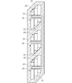
- the figure which shows the structure of the accommodating part of FIG. 1 typically.
- the figure for demonstrating the efficiency of picking work. 9 is a table showing an example of a correspondence relationship between the types of works corresponding to products manufactured in a predetermined period and the types of parts used for the works.
- the figure which shows an example of the parts group temporarily determined so that the 1 row 1 pick condition may be satisfy
- FIG. 9 is a diagram when non-group components are arranged in the empty accommodation space of the accommodation unit shown in FIG. 8.
- FIG. 9B is a diagram schematically showing the arrangement of the components stored in the accommodation portion of FIG. 9A, which is viewed from above.
- the block diagram which shows the principal part structure of the components management system containing the components storage position determination apparatus which concerns on embodiment of this invention. 6 is a flowchart showing an example of processing executed by the component storage position determination device according to the embodiment of the present invention.
- the figure which shows the modification of FIG. The figure which shows another modification of FIG.
- the figure which shows another modification of FIG. is a flowchart showing an example of processing executed by the component storage position determination device according to the embodiment of the present invention.
- the figure which shows the modification of FIG. The figure which shows another modification of FIG.
- a parts storage position determination device is a device for managing parts of various products produced according to a production plan, that is, a plurality of types of parts to be assembled on a work corresponding to a plurality of types of products.
- the products include not only finished products but also products before completion (intermediate products).
- the work is put on the production line corresponding to various products such as vehicles and engines, and various paints are applied in the painting process in addition to the body frame and engine block where various parts are assembled in the assembly process. Etc. are also included.
- the parts include parts to be assembled to the work in the assembly process, various paints applied to the work in the painting process, tools and jigs used in the various processes, and the like.
- FIG. 1 is a diagram showing an example of a serving to which a component storage position determination device according to an embodiment of the present invention is applied.
- the components 21 used for a predetermined period are a plurality of rows (five rows in the figure) and a plurality of rows (three rows in the figure) facing the passages 22 and 23 on the loading side and the removal side of the components 21, respectively. It is arranged on a shelf (accommodation portion) 20 having an accommodation space of.
- the component storage position determination device determines the storage position of each component 21 in the accommodating portion 20 by designating the column and the row of the shelf.
- the worker P2 on the aisle 23 side picks the put-in component 21.
- the components 21 may be loaded and picked automatically by a facility such as a robot.
- the determined storage position is output to the facility controller or the like.
- the parts 21 put into the storage position are sequentially sent from the putting side to the taking out side by a pipe shooter, a conveyor or the like in the order of putting.
- the components can also be supplied from the take-out side (the passage 23 side) of the housing section 20.
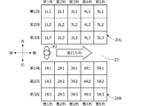
- FIG. 2 is a diagram schematically showing the configuration of the accommodation unit 20.
- the front-rear direction and the left-right direction are defined with reference to the worker P2 who performs the picking work as illustrated.
- the accommodating portion 20 is provided on each of the left and right sides of the take-out side passage 23, and these are represented as accommodating portions 20L and 20R, respectively.
- Each of the storage units 20L and 20R has a plurality of rows (5 rows) partitioned in a plurality of rows (3 rows) in the vertical direction along the traveling direction of the picking work indicated by the arrow, that is, along the path of the worker P2.
- each storage position is specified by using numbers (1 to 5) representing columns, letters (L, R) representing left and right, and numbers (1 to 3) representing columns.
- the storage position of the third row in the second row on the left side is represented by "2L3".
- Each accommodation space is shown as having the same depth (horizontal length), frontage (front-back length), and height (vertical length) for convenience, but the depth, frontage, and height of each accommodation space are shown.
- the length can be changed arbitrarily. For example, it is possible to change the length or the number of pipes or the like constituting the shelf, or change the partition position of the shelf to reduce the number of rows to 4 or less, 6 or more, and the number of rows to 2 or less, or 4 or more. ..
- Each component 21 is placed directly in the storage position or in a state of being housed in a container having an opening on the upper side and the left and right sides.
- a container having the same shape can be used regardless of the type of the component.
- each accommodation space of the accommodation unit 20 is determined in advance to have a certain frontage and height according to the width and height of the container. It should be noted that different containers may be used depending on the shapes and types of parts.
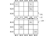
- FIG. 3 is a diagram for explaining the efficiency of the picking work, and the accommodation space of FIG. 2 is shown.
- the parts necessary for allocating a specific work are stored in storage positions 1L1, 2R2, 4L1, 4L2, 4R1, 5R3.
- picking work is performed once in each row, but in the third row, the picking work is not performed (passing), and the picking for the walking amount of the worker is performed.
- Work efficiency is reduced.
- the picking work is performed from the plurality of storage positions 4L1, 4L2, and 4R1 in the fourth row, the required time becomes long. Therefore, when the plurality of workers sequentially perform the picking work, the fourth row becomes a bottleneck. (Traffic), the efficiency of the overall picking work is reduced.
- the component storage position determination device is configured as follows so as to suppress the occurrence of straight passage and congestion in each row of the storage units 20 regardless of the type of work and to efficiently perform the picking work. To do.
- the component storage position determination device of this embodiment determines the storage position of the component 21 in consideration of the following three conditions. 1.1 Column 1 pick condition 2. Combination optimization condition 3. Layout condition
- the one-row, one-pick condition is a condition that, when the worker P2 advances along the passage 23, at least one component is picked for each row of the shelves of the accommodation unit 20.
- the combination optimization condition is a condition for optimizing the accommodation efficiency of the components 21 arranged in each accommodation space of the accommodation unit 20.
- the layout condition is a condition for efficiently laying out the accommodation unit 20.
- the one-row, one-pick condition is a condition that at least one part is picked in each row of the accommodating unit 20, regardless of the type of work to be delivered, that is, the work corresponding to the product produced in a predetermined period.
- the one-row/one-pick condition is a condition for improving the efficiency of the picking work with respect to the walking amount of the worker P2 by suppressing the occurrence of straight passage in each row of the accommodation unit 20.
- the components 21 stored in the storage unit 20 are classified into component groups stored in the same column of the storage unit 20 in consideration of the picking condition per row and one pick.
- FIG. 4 is a table showing an example of the correspondence relationship between the types of works corresponding to products manufactured in a predetermined period and the types of parts 21 used for the works.
- the types of parts 21 (P01 to P27 in the figure) used for each work differ depending on the type of work (A1 to D6 in the figure) such as model and specifications.
- the parts P01, P02, P04, P10, P12, P15, P17, P23 are used for the work A1. That is, when arranging the work A1, these parts 21 are picked from the housing portion 20.
- FIG. 5 is a diagram showing an example of a part group provisionally determined so as to satisfy the one-column, one-pick condition.
- the 27 types of components P01 to P27 shown in FIG. 4 are sequentially classified into five component groups Gr1 to Gr5 corresponding to the five columns of the accommodating portion 20 based on the correspondence relationship between the type of work and the type of component 21. To be done.
- the part group is examined for the part P01. As shown in the correspondence relationship of FIG. 4, since the part P01 is used for all the works, even if the part P01 is stored in a single row by itself, no pass-through occurs regardless of the type of works to be arranged. .. As shown in FIG. 5, such a component P01 is provisionally determined as one component group Gr1 independently.
- the part group is examined for the part P02. Since the part P02 is not used in the works C1 and C2, if the parts P02 are stored alone in a single row, a pass-through occurs when the works C1 and C2 are arranged.
- a component P02 is provisionally determined as a component group Gr2 in combination with any one of the components P03, P07, P09, and P11.
- the component P02 is provisionally determined as one component group Gr2 in combination with the component P03.
- the part P04 that is not used in the works A3, B1 to B3, C1, C2, D3 to D5 is provisionally determined as a part group Gr3 in combination with any one of the parts P05, P06, P08 and the parts P03, P07, P09, P11.
- the component P04 is provisionally determined as one component group Gr3 in combination with the components P05, P06, P08 and the component P07 (components P05 to P08).
- the part group is examined for the part P09.
- the part P09 which is not used in the works A1 to B4 and D1 to D6, is provisionally determined as one part group Gr4 in combination with the part P10.
- the component group is examined for the component P11.
- the part P11 that is not used in the works A1 to B4 and D1 to D6 is provisionally determined as one part group Gr5 in combination with the parts P12 to P14.
- the parts group is examined for the parts P15 to P27, but the parts P15 to P27 cannot avoid passing through when serving in a predetermined period by any combination.
- Such parts P15 to P27 are provisionally determined as non-group parts.
- a penalty score corresponding to each condition is set. For example, if there is a column that does not satisfy the one-column-one-pick condition, 50000 points are added as a penalty score. In addition, in order to suppress the occurrence of traffic congestion in each row of the storage unit 20, for example, when picking work is performed twice or more in a single row, one point is added as a penalty score.
- the storage position corresponding to the combination with the smallest total penalty score is finally determined as the optimum storage position.
- the storage position may be determined when a combination in which the total value of the penalty points is equal to or less than a preset threshold value is determined.
- a threshold of the penalty score may be set for each condition.
- the combination optimizing condition is a condition for optimizing the accommodation efficiency of the components 21 arranged in the respective accommodation spaces of the accommodation unit 20, and the components having the same depth, frontage, and height of the required accommodation spaces are to be provided. It is a condition for effectively using the accommodation space by storing them in the same row.
- the non-group parts P15 to P27 provisionally determined to satisfy the one-column, one-pick condition are classified into the component groups Gr1 to Gr5 provisionally determined to satisfy the one-column, one-pick condition in consideration of the combination optimization condition. To be done. When the number of provisionally determined parts groups is less than 5, non-group parts are combined.
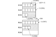
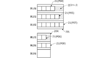
- FIGS. 6A and 6B are diagrams schematically showing an example of the arrangement of the components (containers containing the components) 21 stored in the accommodation unit 20, and the accommodation unit 20L in which the component group Gr3 of FIG. 5 is arranged. , 20R when viewed from the front and rear sides, showing the arrangement of the parts 21.
- the accommodating efficiency of the components 21 arranged in the respective accommodating spaces of the accommodating portion 20 is the same as that of the accommodating portions 20L and 20R when the plurality of components 21 (components P04 to P08 in the figure) classified into the component group (component group Gr3 in the figure) are included. It changes depending on where it is stored.
- an empty space for at least four containers is created in the depth direction in the accommodation unit 20L in which four containers, five containers, and two parts P04 to P06 are arranged, respectively. Further, in the housing portion 20R in which the six containers and the parts P07 and P08 for the three containers are respectively arranged, an empty space for at least three containers is formed in the depth direction. In this case, an empty space for at least 7 containers occurs in the depth direction in the entire row.
- an empty space for at least three containers is created in the depth direction in the accommodation unit 20L in which four, five, and six parts P04, P05, P07 are arranged.
- an empty space for at least one container is formed in the depth direction in which the components P06 and P08 for two containers and three containers, respectively, are arranged. In this case, an empty space for at least four containers is generated in the entire row.
- the storage efficiency of the components 21 arranged in the storage portions 20L and 20R in the depth direction changes depending on the combination of the storage positions of the components 21.
- a penalty score is also set for the combination optimization condition. For example, if the depth of the accommodation space required for the components 21 stored in a single row is not aligned for each stage, one penalty point is added according to the empty space.
- the storage efficiency in the frontage direction and the height direction can be similarly considered.
- the layout condition is a condition for efficiently laying out the accommodating unit 20, and the arrangement of each column is such that the depth of each column of the accommodating unit 20 gradually changes along the traveling direction of the worker P2, for example, linearly. This is a condition for effectively using the space in the factory by combining.
- the layout efficiency of the storage units 20L and 20R in the space in the factory changes depending on how the rows in which the component groups Gr1 to Gr5 are stored are arranged.
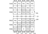
- FIGS. 7A and 7B are diagrams schematically showing an example of the arrangement of the components (containers in which the components are stored) 21 stored in the storage unit 20, and when the storage units 20L and 20R are viewed from above, The arrangement of the components 21 in the row having the maximum depth in each column is shown.
- FIG. 7A for the third row of the storage unit 20L in which the parts P04, P05, P07 (FIG. 6B) classified into the part group Gr3 are stored, the third stage in which the parts P07 for six containers are arranged.
- FIG. 7A for the third row of the storage unit 20L in which the parts P04, P05, P07 (FIG. 6B) classified into the part group Gr3 are stored, the third stage in which the parts P07 for six containers are arranged.
- FIG. 7A for the third row of the storage unit 20L in which the parts P04, P05, P07 (FIG. 6B) classified into the part group Gr3 are stored, the third stage in which the parts P07 for six
- the component groups Gr1 to Gr5 having maximum depths of four containers, three containers, six containers, one container, and five containers are arranged along the traveling direction of the worker P2. To be done. In this way, when the depth of each row of the housing portion 20 does not gradually change along the traveling direction of the worker P2, the entire shape of the housing portion 20 is arranged into a linear shape along the passages 22 and 23. However, it is difficult to efficiently lay out the accommodating portion 20 in the space in the factory.
- the maximum depths are six containers, five containers, four containers, three containers, and one component group Gr3, Gr5. , Gr1, Gr2, Gr4 are arranged.
- the entire shape of the accommodating portion 20 is arranged into a linear shape along the passages 22 and 23, The housing section 20 can be efficiently laid out in the space in the factory.
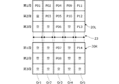
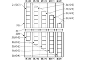
- FIG. 8 is a diagram schematically showing the arrangement of the components 21 stored in the storage units 20L and 20R of FIG. 7B as viewed from the left and right sides, and the components P01 to P14 provisionally determined in the component groups Gr1 to Gr5. Shows the arrangement of.
- FIG. 9A is a diagram when the non-group components P15 to P27 are arranged in the empty accommodation spaces of the accommodation units 20L and 20R shown in FIG. 8, and
- FIG. 9B is the accommodation unit 20L of FIG. It is a figure which shows schematically the arrangement
- the provisionally determined non-group components P15 to P27 are assigned to the respective component groups Gr1 to Gr5 so as to have the target depths of the respective columns defined as shown by the broken lines in FIG. 7B. They are sorted and placed in empty storage spaces (tiers) in each row. As a result, as shown in FIG. 9B, the columns of the accommodating portions 20 are arranged such that the depth of the columns of the accommodating portions 20 gradually changes along the traveling direction of the worker P2.
- FIG. 10 is a diagram showing an example of the layout of the accommodation section 20 as viewed from above.
- the accommodating portion 20 in which the components 21 are arranged as shown in FIGS. 9A and 9B is arranged in a linear shape along the passages 22 and 23 to efficiently lay out the space in the factory. can do.
- the overall shape of the storage units 20L and 20R viewed from above into a substantially triangular shape or a substantially trapezoidal shape, the storage units 20 and the passages 22 and 23 can be efficiently laid out.
- a penalty score is set for the layout condition. For example, when the depth of each column of the accommodating portion 20 does not gradually increase or decrease along the traveling direction, a penalty score of 50 is added according to the number of columns that do not satisfy the condition.
- the work efficiency of the worker P1 who puts the component 21 into the accommodation unit 20 can be considered. That is, if the depth of the accommodation unit 20 is restricted, the same type of component 21 is arranged in a plurality of storage positions. In such a case, however, if the same type of component 21 is arranged in storage positions separated from each other. The input work becomes complicated, and the work efficiency decreases. Therefore, for example, when parts 21 of the same type are arranged in different rows, the penalty score is 1, and in this case, when parts 21 of the same type are stored in rows that are not adjacent to each other, One point is added as a penalty score.
- FIG. 11 is a block diagram showing a main configuration of a parts management system 100 including the parts storage position determination device 10 according to the embodiment of the present invention.
- the component management system 100 includes a component storage position determination device (hereinafter, referred to as a device) 10 that determines a storage position of a component, a storage unit 20 that stores the component, and a component storage position determination device that stores the components determined by the device 10. And a display unit 30 for displaying the storage position.
- a component storage position determination device hereinafter, referred to as a device 10 that determines a storage position of a component
- a storage unit 20 that stores the component
- a component storage position determination device that stores the components determined by the device 10.
- a display unit 30 for displaying the storage position.
- the device 10 is configured to include an arithmetic processing unit having a CPU 11, a memory 12 such as a ROM and a RAM, and other peripheral circuits such as an I/O interface.
- An input unit 13 including a keyboard, a mouse, a touch panel, and the like, and a display unit 30 including a liquid crystal display and the like are connected to the device 10 by wire or wirelessly.
- the input unit 13 Through the input unit 13, the number of rows and the number of stages of the storage units 20L and 20R, the correspondence relationship between the type of work and the type of parts corresponding to the product produced in a predetermined period (FIG. 4), the number of production of each work, and The number of each component to be assembled to each work (the number stored in the housing portion 20) and the like are input.
- these threshold values When there is a constraint on the space in which the accommodating portion 20 can be arranged in the depth, frontage, or height direction of the accommodating portion 20, these threshold values are also input.
- the penalty score corresponding to each condition is input.
- Various types of information input via the input unit 13 are stored in the memory 12.
- the CPU 11 includes a group determination unit 14 that determines a component group stored in the same column of the accommodation unit 20 based on the correspondence relationship stored in the memory 12, and a layout determination unit 15 that determines the layout of the column for each component group. It functions as an optimum position determination unit 16 that determines the optimum storage position of the component 21 and an output unit 17 that outputs the determined storage position of the component 21 to the display unit 30.
- the group determination unit 14 tentatively determines a component group and a non-group component so as to satisfy the one-column, one-pick condition based on the correspondence between the type of work and the type of component stored in the memory 12. Further, the non-group parts are classified into parts groups in consideration of the combination optimization condition, and the parts group is finally determined.
- the layout determination unit 15 determines the layout of the column for each component group provisionally determined by the group determination unit 14 in consideration of the layout condition.
- the group determination unit 14 classifies the non-group components into the component groups arranged by the layout determination unit 15 and finally determines the component group. As a result, the combination of the storage positions of the components 21 in the storage section 20 is determined.
- the optimum position determination unit 16 calculates a penalty score for the combination of the storage positions of the components 21 determined by the group determination unit 14 and the layout determination unit 15, and based on the calculated penalty score, the optimum position of the components 21 in the storage unit 20.
- the appropriate storage location For example, a penalty score is calculated for each of a plurality of combinations of storage positions of the parts 21, and the storage position with the minimum penalty score is determined as the optimum storage position.
- the penalty score may be calculated for each combination of the storage positions of the components 21, and the storage position at which the penalty score is equal to or less than the threshold value may be determined as the optimum storage position.
- the output unit 17 outputs the storage position of the component 21 in the accommodation unit 20 determined by the optimum position determination unit 16 to the display unit 30.
- the determined storage position may be output to the facility controller or the like.
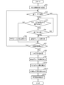
- FIG. 12 is a flowchart showing an example of processing executed by the device 10 according to a program stored in the memory in advance. The process shown in this flowchart is executed when various information is input via the input unit 13.
- step S1 the correspondence between the type of work and the type of part stored in the memory 12 (FIG. 4) is read by the processing of the group determination unit 14.
- step S2 based on the correspondence relationship read in step S1, it is determined for each component 21 whether or not it is used in all workpieces. If the result in step S2 is negative, the process proceeds to step S3, and if the result is affirmative, the process proceeds to step S5.
- step S3 it is determined whether or not it will be used for all workpieces by combining it with other parts 21 that have not been examined. If the result in step S3 is affirmative, the process proceeds to step S4, and if the result is negative, the process proceeds to step S6. In step S4, it is determined whether or not the combination in step S3 is possible based on the threshold values of the depth, the frontage, or the height of the accommodation unit 20 stored in the memory 12. When the result in step S4 is negative, the process returns to step S3.
- step S2 If the result in step S2 or S4 is affirmative, the process proceeds to step S5, in which a parts group is provisionally determined. On the other hand, if the result in step S3 is negative, the process proceeds to step S6, in which the component 21 is provisionally determined as a non-group component.
- step S7 it is determined whether or not there is an unexamined part 21. If the result in step S7 is affirmative, the process returns to step S2, and if the result is negative, the process proceeds to step S8.
- step S8 the layout determining unit 15 determines the column layout for each component group temporarily determined in step S5 in consideration of the layout conditions.
- step S9 the non-group components provisionally determined in step S6 are classified into the component groups arranged in step S8 by the process of the group determination unit 14, and the component group is finally determined. That is, in steps S8 and S9, the combination of the storage positions of the components 21 in the accommodation portion 20 is determined.
- step S10 the optimal position determination unit 16 calculates a penalty score for the combination of the storage positions of the components 21 in the accommodation unit 20 determined in steps S8 and S9 by the processing.
- step S11 the optimum storage position of the component 21 in the accommodation unit 20 is determined based on the penalty score calculated in step S10.
- step S12 the storage position determined in step S11 is output to the display unit 30 by the process of the output unit 17.
- the component 21 delivered to the factory is put into the storage unit 20 and stored according to the storage position displayed on the display unit 30 by the worker P1 (step S12 in FIG. 12). Since the storage positions of the same type of components 21 are designated close to each other (steps S10 and S11), the efficiency of the insertion work by the worker P1 can be improved.
- the component 21 stored in the storage unit 20 is picked from the storage unit 20 according to the storage position displayed on the display unit 30 by the worker P2 (step S12). Since the parts 21 necessary for arranging each work are distributed and stored in each row (steps S1 to S7 and S9 to S11), the efficiency of the picking work by the worker P2 is improved regardless of the type of the work. be able to.
- the depth, frontage, and height of the shelf of the accommodation unit 20 are adjusted by changing the length, the number of pipes, and the partition position of the pipes that make up the shelf according to the arrangement of the components 21 to be stored. Since the components 21 having the same depth, frontage, and height of the accommodation space required for storage are arranged in the same row (S9 to S11), the accommodation efficiency of the components 21 arranged in the respective accommodation spaces of the accommodation portion 20 Can be improved.
- the entire storage units 20 are arranged in a substantially triangular shape. (Fig. 9B). As a result, as shown in FIG. 10, the layout efficiency of the housing portion 20 and the passages 22 and 23 in the space in the factory can be improved.
- the device 10 is a housing part having a plurality of rows of housing spaces facing the passages 22 and 23 of a plurality of types of parts 21 to be assembled to a work corresponding to a plurality of types of products produced in a predetermined period according to a production plan. Determine the storage location at 20.
- the device 10 stores a correspondence relationship between a type of work corresponding to a product produced in a predetermined period and a type of a part 21 assembled for each type of work, and a correspondence relationship stored in the memory 12.
- the layout deciding unit 15 and the optimum position deciding unit 16 (CPU 11) for deciding the storage positions of the plural kinds of components 21 in the accommodating unit 20, and the output unit 17 (for outputting the decided storage positions).
- the group deciding unit 14 and the optimum position deciding unit 16 are arranged so that a plurality of types of components 21 corresponding to respective works are distributed and arranged in all of the plurality of rows of the accommodating unit 20.
- the storage position of the part 21 is determined (FIG. 5).
- the layout determining unit 15 and the optimum position determining unit 16 are arranged in the accommodation unit 20 according to the length in the depth direction intersecting the passage 23 required when storing the components 21 in each of the plurality of rows of the accommodation unit 20.
- the row in which each of the plurality of types of parts 21 is stored is determined (FIG. 7B).
- Each of the plurality of rows of the accommodating portion 20 has a plurality of steps in the height direction intersecting the passage 23 (FIG. 1 ).
- the group determination unit 14 and the optimum position determination unit 16 have a plurality of types in the accommodation unit 20 so that the lengths in the depth direction required when storing the components 21 in a plurality of stages of the plurality of columns of the accommodation unit 20 are uniform.
- the storage position of the component 21 is determined (FIG. 6B). Thereby, the accommodation efficiency of the components 21 arranged in the respective accommodation spaces of the accommodation section 20 can be improved.
- the group determination unit 14 and the optimum position determination unit 16 determine the number of times when the components 21 are stored in each of the plurality of rows of the storage unit 20, or the number of the components 21 stored in each of the plurality of columns of the storage unit 20.
- the storage positions of the plurality of types of components 21 in the accommodation unit 20 are determined so that the number of times of taking out is uniform. As a result, it is possible to suppress the occurrence of traffic congestion in each row of the accommodating portions 20, and improve the efficiency of the picking work by the worker P2 regardless of the type of work.
- the accommodation space of the accommodation portion 20 has five rows, three steps on each of the left and right sides, the frontage and the height are common, but the accommodation portion having a plurality of rows of accommodation spaces facing the passage is not limited to this. .. Further, although the housings 20L and 20R are arranged on both sides of the single passage 23, the layout of the housings is not limited to this.
- FIGS. 13A to 13C are diagrams showing modified examples of the layout of the accommodation unit 20.
- a plurality of accommodating portions 20 may be arranged facing a plurality of passages 23 depending on the shape of the space in the factory.
- the layout is such that the route of the worker P2 is branched as shown in FIG. 13B, and the storage area for common parts used in all types (see the figure A center) and a storage area (upper and lower in the figure) for exclusive parts for each model may be provided.
- the group determination unit 14, the layout determination unit 15, and the optimum position determination unit 16 determine the storage positions of the plurality of types of components 21 in the accommodation unit 20.
- the calculation unit that determines the storage positions of the plurality of types of components in the storage unit is not limited to this. For example, it is possible to assume a plurality of columns and layouts of the accommodating section 20 and determine the optimal component storage position in each case, and determine the number of columns and layout that minimize the penalty score.
- the memory 12 of the apparatus 10 stores the correspondence between the type of work and the type of parts, but stores the correspondence between the type of work and the type of parts assembled for each type of work.
- the storage unit to perform is not limited to this.
- the storage unit may be provided separately from the device 10, and for example, an external memory connected to the device 10 or a storage area on a server may be used as the storage unit.
- a unit that reads out various information from the storage unit is called an arithmetic unit.
- 10 parts storage position determination device (device), 11 CPU, 12 memory, 13 input unit, 14 group determination unit, 15 layout determination unit, 16 optimal position determination unit, 17 output unit, 20 (20L, 20R) accommodation unit, 21 Parts, 22 input side passage, 23 extraction side passage, 30 display section, 100 parts management system
Landscapes
- Business, Economics & Management (AREA)
- Engineering & Computer Science (AREA)
- Economics (AREA)
- Mechanical Engineering (AREA)
- Marketing (AREA)
- Strategic Management (AREA)
- Entrepreneurship & Innovation (AREA)
- Human Resources & Organizations (AREA)
- Finance (AREA)
- Operations Research (AREA)
- Quality & Reliability (AREA)
- Development Economics (AREA)
- Tourism & Hospitality (AREA)
- Physics & Mathematics (AREA)
- General Business, Economics & Management (AREA)
- General Physics & Mathematics (AREA)
- Theoretical Computer Science (AREA)
- Accounting & Taxation (AREA)
- Warehouses Or Storage Devices (AREA)
Abstract
Description
1.1列1ピック条件
2.組合せ最適化条件
3.レイアウト条件
(1)装置10は、生産計画に従って所定期間に生産される複数種類の製品に対応したワークに組み付けられる複数種類の部品21の、通路22,23に面した複数列の収容空間を有する収容部20における保管位置を決定する。
Claims (6)
- 生産計画に従って所定期間に生産される複数種類の製品に対応したワークに組み付けられる複数種類の部品の、通路に面した複数列の収容空間を有する収容部における保管位置を決定する部品保管位置決定装置であって、
前記所定期間に生産される製品に対応したワークの種類と、ワークの種類毎に組み付けられる部品の種類との対応関係を記憶する記憶部と、
前記記憶部に記憶された前記対応関係に基づいて、前記収容部における複数種類の部品の保管位置を決定する演算部と、
前記演算部により決定された保管位置を出力する出力部と、を備え、
前記演算部は、それぞれのワークに対応する複数種類の部品が前記収容部の複数列のすべてにそれぞれ分散して配置されるように、前記収容部における複数種類の部品の保管位置を決定することを特徴とする部品保管位置決定装置。 - 請求項1に記載の部品保管位置決定装置において、
前記演算部は、前記収容部の複数列のそれぞれに前記部品を保管するときに要する前記通路に交差する奥行方向の長さに応じて、前記収容部において複数種類の部品のそれぞれが保管される列を決定することを特徴とする部品保管位置決定装置。 - 請求項2に記載の部品保管位置決定装置において、
前記収容部の複数列のそれぞれは、前記通路に交差する高さ方向に複数段を有し、
前記演算部は、前記収容部の複数列のそれぞれについて複数段のそれぞれに前記部品を保管するときに要する前記奥行方向の長さが揃うように、前記収容部における複数種類の部品の保管位置を決定することを特徴とする部品保管位置決定装置。 - 請求項1~3のいずれか1項に記載の部品保管位置決定装置において、
前記演算部は、前記収容部の複数列のそれぞれに前記部品を保管するときの回数、または、前記収容部の複数列のそれぞれに保管された前記部品を取り出すときの回数が揃うように、前記収容部における複数種類の部品の保管位置を決定することを特徴とする部品保管位置決定装置。 - 生産計画に従って所定期間に生産される複数種類の製品に対応したワークに組み付けられる複数種類の部品を管理する部品管理システムであって、
請求項1~4のいずれか1項に記載の部品保管位置決定装置と、
前記部品を保管する収容部と、
前記出力部により出力された保管位置を表示する表示部と、を備えることを特徴とする部品管理システム。 - 生産計画に従って所定期間に生産される複数種類の製品に対応したワークに組み付けられる複数種類の部品の、通路に面した複数列の収容空間を有する収容部における保管位置を決定する部品保管位置決定方法であって、
予め記憶された、前記所定期間に生産される製品に対応したワークの種類と、ワークの種類毎に組み付けられる部品の種類との対応関係に基づいて、前記収容部における複数種類の部品の保管位置を決定する手順と、
決定した保管位置を出力する手順と、を含み、
決定する手順は、それぞれのワークに対応する複数種類の部品が前記収容部の複数列のすべてにそれぞれ分散して配置されるように、前記収容部における複数種類の部品の保管位置を決定することを特徴とする部品保管位置決定方法。
Priority Applications (4)
| Application Number | Priority Date | Filing Date | Title |
|---|---|---|---|
| CN202080013230.5A CN113412228B (zh) | 2019-02-21 | 2020-02-12 | 零件保管位置决定装置、零件保管位置决定方法以及零件管理系统 |
| JP2021501883A JP7124200B2 (ja) | 2019-02-21 | 2020-02-12 | 部品保管位置決定装置、部品保管位置決定方法および部品管理システム |
| US17/428,952 US12091252B2 (en) | 2019-02-21 | 2020-02-12 | Parts storage position determination apparatus, parts storage position determination method and parts management system |
| CA3130737A CA3130737A1 (en) | 2019-02-21 | 2020-02-12 | Parts storage position determination apparatus, parts storage position determination method and parts management system |
Applications Claiming Priority (2)
| Application Number | Priority Date | Filing Date | Title |
|---|---|---|---|
| JP2019-029075 | 2019-02-21 | ||
| JP2019029075 | 2019-02-21 |
Publications (1)
| Publication Number | Publication Date |
|---|---|
| WO2020170898A1 true WO2020170898A1 (ja) | 2020-08-27 |
Family
ID=72144904
Family Applications (1)
| Application Number | Title | Priority Date | Filing Date |
|---|---|---|---|
| PCT/JP2020/005251 Ceased WO2020170898A1 (ja) | 2019-02-21 | 2020-02-12 | 部品保管位置決定装置、部品保管位置決定方法および部品管理システム |
Country Status (5)
| Country | Link |
|---|---|
| US (1) | US12091252B2 (ja) |
| JP (1) | JP7124200B2 (ja) |
| CN (1) | CN113412228B (ja) |
| CA (1) | CA3130737A1 (ja) |
| WO (1) | WO2020170898A1 (ja) |
Citations (5)
| Publication number | Priority date | Publication date | Assignee | Title |
|---|---|---|---|---|
| JPS5812504U (ja) * | 1981-07-13 | 1983-01-26 | 株式会社日立製作所 | 自動倉庫の運用制御装置 |
| JPH09150923A (ja) * | 1995-11-27 | 1997-06-10 | Dainippon Printing Co Ltd | ピッキング前物品の配置最適化方法 |
| JP2005119787A (ja) * | 2003-10-15 | 2005-05-12 | Toyota Industries Corp | 自動倉庫の管理装置及び自動倉庫の管理プログラム |
| JP2011215992A (ja) * | 2010-04-01 | 2011-10-27 | Panasonic Electric Works Co Ltd | 部品管理システムおよび部品管理方法 |
| JP2018188236A (ja) * | 2017-04-28 | 2018-11-29 | 村田機械株式会社 | ピッキングシステム |
Family Cites Families (10)
| Publication number | Priority date | Publication date | Assignee | Title |
|---|---|---|---|---|
| JPH0891516A (ja) * | 1994-09-27 | 1996-04-09 | Mazda Motor Corp | 部品供給表示装置 |
| JPH08217210A (ja) * | 1995-02-13 | 1996-08-27 | Kubota Corp | 部品のピッキング指示方法 |
| JPH10236614A (ja) * | 1997-02-28 | 1998-09-08 | Hitachi Ltd | 部品在庫配膳システム |
| JP2001101325A (ja) * | 1999-09-30 | 2001-04-13 | Nec Corp | 資材所要量管理システム及び資材所要量管理プログラムを記録したコンピュータ読取可能な記録媒体 |
| DE102004028743A1 (de) * | 2003-06-20 | 2005-03-03 | Omron Corp. | Arbeitsunterstützungsvorrichtung |
| US7881820B2 (en) | 2006-08-30 | 2011-02-01 | Amazon Technologies, Inc. | Method and system for inventory placement according to expected item picking rates |
| JP5688864B2 (ja) * | 2013-09-03 | 2015-03-25 | 株式会社レクサー・リサーチ | 生産システムシミュレーション装置、生産システムシミュレーション方法及び生産システムシミュレーションプログラム |
| JP6443538B2 (ja) * | 2015-03-31 | 2018-12-26 | 富士通株式会社 | 部材の管理状況監視プログラム、部材の管理状況監視方法および部材の管理状況監視装置 |
| DE102016108677A1 (de) * | 2016-05-11 | 2017-11-16 | nextLAP GmbH | Verfahren zum Betreiben einer Teile-Ablage |
| US10504055B2 (en) * | 2016-09-02 | 2019-12-10 | X Development Llc | Optimization of warehouse layout based on customizable goals |
-
2020
- 2020-02-12 JP JP2021501883A patent/JP7124200B2/ja active Active
- 2020-02-12 CN CN202080013230.5A patent/CN113412228B/zh not_active Expired - Fee Related
- 2020-02-12 CA CA3130737A patent/CA3130737A1/en active Pending
- 2020-02-12 WO PCT/JP2020/005251 patent/WO2020170898A1/ja not_active Ceased
- 2020-02-12 US US17/428,952 patent/US12091252B2/en active Active
Patent Citations (5)
| Publication number | Priority date | Publication date | Assignee | Title |
|---|---|---|---|---|
| JPS5812504U (ja) * | 1981-07-13 | 1983-01-26 | 株式会社日立製作所 | 自動倉庫の運用制御装置 |
| JPH09150923A (ja) * | 1995-11-27 | 1997-06-10 | Dainippon Printing Co Ltd | ピッキング前物品の配置最適化方法 |
| JP2005119787A (ja) * | 2003-10-15 | 2005-05-12 | Toyota Industries Corp | 自動倉庫の管理装置及び自動倉庫の管理プログラム |
| JP2011215992A (ja) * | 2010-04-01 | 2011-10-27 | Panasonic Electric Works Co Ltd | 部品管理システムおよび部品管理方法 |
| JP2018188236A (ja) * | 2017-04-28 | 2018-11-29 | 村田機械株式会社 | ピッキングシステム |
Also Published As
| Publication number | Publication date |
|---|---|
| CN113412228B (zh) | 2022-09-27 |
| CN113412228A (zh) | 2021-09-17 |
| US20220135327A1 (en) | 2022-05-05 |
| US12091252B2 (en) | 2024-09-17 |
| JPWO2020170898A1 (ja) | 2021-12-09 |
| JP7124200B2 (ja) | 2022-08-23 |
| CA3130737A1 (en) | 2020-08-27 |
Similar Documents
| Publication | Publication Date | Title |
|---|---|---|
| CN110716452A (zh) | 一种基于多层穿梭车智能立体仓库的调度仿真方法 | |
| Koster et al. | Routing orderpickers in a warehouse: a comparison between optimal and heuristic solutions | |
| US7221983B2 (en) | Production cell | |
| CN110817223A (zh) | 一种基于堆垛机智能立体仓库的调度仿真方法 | |
| CN112875112A (zh) | 基于数字孪生的高密度立体仓库库位分配与调度方法 | |
| JPWO2019142499A1 (ja) | シミュレーションシステム、およびシミュレート方法 | |
| CN115115300A (zh) | 一种考虑三维装箱的循环取货路径规划方法 | |
| WO2020170898A1 (ja) | 部品保管位置決定装置、部品保管位置決定方法および部品管理システム | |
| JP2021165926A (ja) | 物流における立体自動倉庫 | |
| Eskandari et al. | Notes on mathematical formulation and complexity considerations for blocks relocation problem | |
| Ghomri et al. | Mathematical modeling of retrieval travel time for flow-rack automated storage and retrieval systems | |
| JPH05135070A (ja) | 配送スケジユーリング装置 | |
| CN111747008A (zh) | 出库定位方法、装置和系统 | |
| JPH0549562B2 (ja) | ||
| CN118296836A (zh) | 一种混线制装配生产线的仿真方法 | |
| JPH10181814A (ja) | 収納割付装置 | |
| JP2002297723A (ja) | 棚配置設計装置、棚配置設計方法並びに当該方法を実行するコンピュータプログラム並びに当該コンピュータプログラムを格納した記憶媒体 | |
| CN110436099B (zh) | 一种不良品拼托方法 | |
| JP7773106B2 (ja) | 作業計画立案プログラム、作業計画立案方法、および情報処理装置 | |
| JPH09150923A (ja) | ピッキング前物品の配置最適化方法 | |
| JP5018429B2 (ja) | 台車シミュレーション装置 | |
| JP7715990B2 (ja) | 情報処理装置、作業計画立案方法、および作業計画立案プログラム | |
| JP7633570B2 (ja) | 情報処理装置、立案方法、および立案プログラム | |
| JP6058578B2 (ja) | 物品保管スペース算出装置 | |
| Pakpahan et al. | Job shop scheduling considering material handling process |
Legal Events
| Date | Code | Title | Description |
|---|---|---|---|
| 121 | Ep: the epo has been informed by wipo that ep was designated in this application |
Ref document number: 20758567 Country of ref document: EP Kind code of ref document: A1 |
|
| ENP | Entry into the national phase |
Ref document number: 2021501883 Country of ref document: JP Kind code of ref document: A |
|
| ENP | Entry into the national phase |
Ref document number: 3130737 Country of ref document: CA |
|
| NENP | Non-entry into the national phase |
Ref country code: DE |
|
| 122 | Ep: pct application non-entry in european phase |
Ref document number: 20758567 Country of ref document: EP Kind code of ref document: A1 |