WO2020166577A1 - 車両のボディ構造 - Google Patents
車両のボディ構造 Download PDFInfo
- Publication number
- WO2020166577A1 WO2020166577A1 PCT/JP2020/005227 JP2020005227W WO2020166577A1 WO 2020166577 A1 WO2020166577 A1 WO 2020166577A1 JP 2020005227 W JP2020005227 W JP 2020005227W WO 2020166577 A1 WO2020166577 A1 WO 2020166577A1
- Authority
- WO
- WIPO (PCT)
- Prior art keywords
- vehicle
- seat
- floor panel
- reinforcing member
- body structure
- Prior art date
- Legal status (The legal status is an assumption and is not a legal conclusion. Google has not performed a legal analysis and makes no representation as to the accuracy of the status listed.)
- Ceased
Links
Images


Classifications
-
- B—PERFORMING OPERATIONS; TRANSPORTING
- B62—LAND VEHICLES FOR TRAVELLING OTHERWISE THAN ON RAILS
- B62D—MOTOR VEHICLES; TRAILERS
- B62D25/00—Superstructure or monocoque structure sub-units; Parts or details thereof not otherwise provided for
- B62D25/20—Floors or bottom sub-units
Definitions
- the present disclosure relates to a vehicle body structure.
- Patent Document 1 discloses a structure in which both left and right ends of a reinforcing member are formed to extend to the left and right sides and rise upward to be connected to the seat back sides on both the left and right sides in a vehicle. ..
- the present disclosure has been made in view of these points, and an object thereof is to provide a vehicle body structure having a floor panel that is difficult to be deformed by a force transmitted from a seat.
- a floor panel forming a floor of a vehicle, a side panel forming a side surface of the vehicle, and a lower end connected to a side end of the floor panel, A seat fixing portion for fixing a seat on the upper surface of the floor panel, and a first region provided on the rear side of the seat fixing portion and in contact with the upper surface of the floor panel and in contact with the inner surface of the side panel. And a first reinforcing member including a second region in which the vehicle body structure is provided.
- the second reinforcing member fixed to the lower surface of the floor panel and extending in the front-rear direction of the vehicle, and an end portion of the first region opposite to the side panel side is
- the second reinforcing member may be located inward of the side panel side end of the second reinforcing member in the vehicle width direction of the vehicle.
- the first reinforcing member may be provided at a position between the seat and a rear seat fixed to the rear of the seat.
- the floor panel is less likely to be deformed by the force transmitted from the seat.
- FIG. 1 is a schematic perspective view of a vehicle provided with a body structure according to this embodiment.
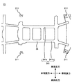
- FIG. 2 shows the body structure as seen from below the vehicle.
- FIG. 3 shows a structure near the first reinforcing member.
- FIG. 1 is a schematic perspective view of a vehicle provided with a body structure 2 according to this embodiment.
- FIG. 2 is a diagram showing the body structure 2 as seen from below the vehicle. 2 is a view showing the body structure 2 as seen from below in the height direction of the vehicle in the area A in FIG.
- the vehicle has a frame 1, a body structure 2, an elastic member 3, and a seat 4.
- the frame 1 extends in the front-rear direction of the vehicle.
- the frame 1 has, for example, a plurality of side members extending in the front-rear direction of the vehicle, and a plurality of cross members extending in the vehicle width direction of the vehicle between the plurality of side members.
- the frame 1 is provided with, for example, a body structure 2 described later and vehicle parts such as an engine and a transmission (not shown).
- the body structure 2 is a vehicle body provided above the frame 1 in the vehicle height direction.
- the body structure 2 constitutes, for example, an engine room, a vehicle compartment, and a luggage compartment. Details of the body structure 2 will be described later.
- the elastic member 3 is provided between the frame 1 and the body structure 2. Specifically, the plurality of elastic members 3 are provided between each of the plurality of mount portions 211 of the floor panel 21 described later and the frame 1.
- the elastic member 3 is made of rubber, for example.
- the vehicle is provided with the elastic member 3 between the frame 1 and the body structure 2 in this manner. For example, the vibration generated in the frame 1 during traveling of the vehicle is absorbed by the elastic member 3, so that Vibration of the body structure 2 due to vibration can be suppressed.
- Seat 4 is a seat on which a vehicle occupant sits.
- the seat 4 is fixed to a seat fixing portion 212 described later.
- the seat 4 is provided with a seat belt fixing portion to which the tip of the seat belt is connected.
- the seat belt fixing portion includes, for example, a receiving side metal fitting into which a buckle provided at the tip of the seat belt is inserted.
- the seat belt is housed in, for example, a winding device provided on a side panel 22 described later.
- the occupant for example, pulls out the seat belt diagonally across the front of the occupant's body from the winding device and attaches the seat belt by connecting the buckle at the tip of the seat belt to the seat belt fixing portion. ..
- the body structure 2 includes a floor panel 21, side panels 22, a first reinforcing member 23, and a second reinforcing member 24.
- the floor panel 21 forms the floor of the vehicle.
- the floor panel 21 has, for example, a plate shape.
- the floor panel 21 has a plurality of mount parts 211 and a seat fixing part 212.
- the mount part 211 is a part for connecting the frame 1 and the floor panel 21.
- the mount portion 211 has, for example, a hole.
- the hole is, for example, a hole into which a bolt is inserted.
- the side panel 22 forms a side surface of the vehicle, and a lower end thereof is connected to a side end of the floor panel 21.
- the seat fixing part 212 is a part for fixing the seat 4 to the upper surface of the floor panel 21.
- the seat fixing portion 212 has, for example, a hole formed in the floor panel 21.
- the seat fixing portion 212 is provided below the seat 4.
- four seat fixing portions 212 arranged in two rows in the front-rear direction of the vehicle and in two rows in the vehicle width direction of the vehicle are provided below one seat 4.
- the seat bracket is a portion for connecting the seat 4 to the floor panel 21.
- FIG. 3 is a diagram showing a structure near the first reinforcing member 23. Note that FIG. 3 is an enlarged view of the vicinity of the first reinforcing member 23 provided near the right end of the floor panel 21 in the vehicle width direction of the area B in the body structure 2 shown in FIG.
- the first reinforcing member 23 reinforces the floor panel 21.
- the first reinforcing member 23 has, for example, a plate shape.
- the first reinforcing member 23 is provided behind the seat fixing portion 212.
- the first reinforcing member 23 is provided, for example, at a position between the second seat 4b and the third seat 4c which is a rear seat fixed to the rear of the second seat 4b.
- the first reinforcing member 23 is provided in a region behind the seat fixing portion 212 of the second seat 4b and in front of the seat fixing portion 212 of the third seat 4c.
- the first reinforcing member 23 has a first area 231 and a second area 232.
- the first region 231 is in contact with the upper surface of the floor panel 21.
- the second region 232 is in contact with the inner surface of the side panel 22.
- the first region 231 is in contact with the upper surface of the floor panel 21 near the side end in the vehicle width direction of the vehicle.
- the second region 232 is in contact with the inner surface of the side panel 22 near the lower end.
- the length of the first area 231 in the vehicle front-rear direction is smaller than the length of the floor panel 21 in the vehicle front-rear direction.
- the length of the first region 231 in the front-rear direction of the vehicle is larger than the length of the vehicle in the front-rear direction between the seat fixing portion 212 of the second seat 4b and the seat fixing portion 212 of the third seat 4c. small.
- the length of the first region 231 in the vehicle width direction of the vehicle is smaller than the length of the floor panel 21 in the vehicle width direction of the vehicle.
- the length of the second region 232 in the front-rear direction of the vehicle is smaller than the length of the side panel 22 in the front-rear direction of the vehicle.
- the length of the second region 232 in the vehicle height direction is smaller than the length of the side panel 22 in the vehicle height direction.
- the case where the force is transmitted from the seat 4 to the floor panel 21 includes, for example, a case where tension is generated in the seat belt due to a frontal collision or a sudden stop of the vehicle.
- tension is generated in the seat belt
- a force for pulling the floor panel 21 upward for example, from the seat 4 to the vicinity of the seat fixing portion 212 of the floor panel 21 is generated via the seat belt fixing portion provided in the seat 4. Transmitted.
- the first reinforcing member 23 is provided behind the seat fixing portion 212 of the floor panel 21, so that the floor panel 21 is prevented from being deformed by the force transmitted from the seat 4 to the floor panel 21. can do.
- the body structure 2 also includes a first region 231 that contacts the upper surface of the floor panel 21 and a second region 232 that contacts the inner surface of the side panel 22. Therefore, in the body structure 2, since the first region 231 is connected to the second region 232, the force transmitted from the seat 4 to the first region 231 via the floor panel 21 causes, for example, the first region 231 to move. The upward movement can be suppressed.
- the body structure 2 has the first reinforcing member 23 including the first region 231 and the second region 232, the floor panel 21 can be made difficult to be deformed by the force transmitted from the seat 4. ..
- the first reinforcing member 23 may include a first member 233 and a second member 234.
- the first reinforcing member 23 is formed by joining the first member 233 and the second member 234.
- the first member 233 includes a first region 231 and a second region 232.
- the second member 234 includes a second region 232.
- the first member 233 and the second member 234 are welded on the side panel 22. Since the first reinforcing member 23 has the second member 234 in addition to the first member 233, the second region 232 in contact with the inner surface of the side panel 22 can be enlarged.
- the body structure 2 can improve the assemblability of the first reinforcing member 23 to the floor panel 21 and the side panel 22.
- the first reinforcing member 23 includes the first member 233 and the second member 234, the variation in the angle between the floor panel 21 and the side panel 22 that occurs when the side panel 22 is attached to the floor panel 21. Can be absorbed and the first reinforcing member 23 can be assembled to the floor panel 21 and the side panel 22.
- the second reinforcing member 24 reinforces the floor panel 21.
- the second reinforcing member 24 has, for example, a hat-shaped cross section.
- the second reinforcing member 24 has, for example, a downwardly convex shape in the vehicle height direction. As shown in FIG. 2, the second reinforcing member 24 is fixed to the lower surface of the floor panel 21 and extends in the front-rear direction of the vehicle.
- the second reinforcing member 24 has two rows of reinforcements 241 in the vehicle width direction of the vehicle, that is, a first reinforcement 241a and a second reinforcement 241b.
- the first reinforcement 241a is a reinforcement provided on the left side in the vehicle width direction of the vehicle.
- the second reinforcement 241b is a reinforcement provided on the right side in the vehicle width direction of the vehicle.
- the end portion of the first region 231 of the first reinforcing member 23 on the side opposite to the side panel 22 side is located inside the end portion of the second reinforcing member 24 on the side panel 22 side in the vehicle width direction of the vehicle. ..
- the end portion of the first region 231 of the first reinforcing member 23 on the right side in the vehicle width direction of the vehicle is closer to the vehicle than the end portion of the first reinforcement 241a on the left side in the vehicle width direction of the vehicle.
- a part of the region including the right end portion of the first reinforcing member 23 overlaps, for example, a linear region of the first reinforcement 241a that extends in the vehicle front-rear direction.
- the left end of the first region 231 of the first reinforcing member 23 in the vehicle width direction of the vehicle is closer to the left side of the second reinforcement 241b in the vehicle width direction of the vehicle than the right side end of the second reinforcement 241b is to the vehicle width direction.
- a part of the region including the left end portion of the first reinforcing member 23 overlaps, for example, a linear region of the second reinforcement 241b that extends in the front-rear direction of the vehicle.
- the body structure 2 thus provided with the first reinforcing member 23 can make it more difficult to deform the floor panel 21 when a force is transmitted from the seat 4 to the floor panel 21.
- first reinforcing member 23 is formed by joining the first member 233 and the second member 234 is shown, but the present invention is not limited to this.
- the first reinforcing member 23 may be formed of one member.
- the vehicle body structure 2 includes a floor panel 21 that forms a floor of the vehicle and a side panel 22 that forms a side surface of the vehicle and has a lower end connected to a side end of the floor panel 21. And a seat fixing portion 212 for fixing the seat 4 on the upper surface of the floor panel 21.
- the body structure 2 is provided behind the seat fixing portion 212 and includes a first region 231 that is in contact with the upper surface of the floor panel 21 and a second region 232 that is in contact with the inner side surface of the side panel 22. It has a first reinforcing member 23.
- the vehicle body structure 2 is thus provided at the rear of the seat fixing portion 212 and is in contact with the first region 231 in contact with the upper surface of the floor panel 21 and the inner surface of the side panel 22.
- the first reinforcing member 23 includes a first area 231 that contacts the upper surface of the floor panel 21 and a second area 232 that contacts the inner surface of the side panel 22.
- the present disclosure has been described using the embodiments, the technical scope of the present disclosure is not limited to the scope described in the above embodiments, and various modifications and changes are possible within the scope of the gist thereof. is there.
- the specific embodiment of device distribution/integration is not limited to the above embodiment, and all or part of the device may be functionally or physically distributed/integrated in arbitrary units.
- You can Further, a new embodiment generated by an arbitrary combination of a plurality of embodiments is also included in the embodiments of the present disclosure. The effect of the new embodiment produced by the combination also has the effect of the original embodiment.
- the body structure 2 according to the present disclosure can prevent the floor panel 21 from being deformed by the force transmitted from the seat 4 by including the first reinforcing member 23.
Landscapes
- Engineering & Computer Science (AREA)
- Chemical & Material Sciences (AREA)
- Combustion & Propulsion (AREA)
- Transportation (AREA)
- Mechanical Engineering (AREA)
- Body Structure For Vehicles (AREA)
Abstract
車両のボディ構造2は、車両の床を形成しているフロアパネル21と、車両の側面を形成しており、下端がフロアパネル21の側端に接続されているサイドパネル22と、フロアパネル21の上面にシート4を固定するためのシート固定部212と、シート固定部212の後方に設けられており、フロアパネル21の上面に接している第1領域231とサイドパネル22の内側面に接している第2領域232とを含む第1補強部材23と、を有する。
Description
本開示は、車両のボディ構造に関する。
従来、車両には、ボディ構造が設けられている。特許文献1には、車両において、補強メンバの左右両端部が、左右両側へ延長形成されていると共に上側へ立ち上げ形成され、左右両側のシートバックサイドに接続されている構造が開示されている。
例えば、車両が、前方衝突したり、急停止したりすることで、シートベルトに張力が生じた場合、フロアパネルにおけるシートが固定されている領域には、シートから伝達される力によって応力が生じる場合がある。この場合、フロアパネルが変形してしまうという問題が生じていた。
そこで、本開示はこれらの点に鑑みてなされたものであり、シートから伝達される力によって変形しづらいフロアパネルを有する車両のボディ構造を提供することを目的とする。
本開示の第1の態様においては、車両の床を形成しているフロアパネルと、前記車両の側面を形成しており、下端が前記フロアパネルの側端に接続されているサイドパネルと、前記フロアパネルの上面にシートを固定するためのシート固定部と、前記シート固定部の後方に設けられており、前記フロアパネルの上面に接している第1領域と前記サイドパネルの内側面に接している第2領域とを含む第1補強部材と、を有することを特徴とする車両のボディ構造を提供する。
また、前記フロアパネルの下面に固定されており、かつ前記車両の前後方向において延伸している第2補強部材をさらに有し、前記第1領域の前記サイドパネル側とは反対側の端部は、前記第2補強部材の前記サイドパネル側の端部よりも、前記車両の車幅方向において内側に位置していてもよい。
また、前記第1補強部材は、前記シートと、前記シートの後方に固定される後方シートとの間の位置に設けられていてもよい。
本開示によれば、車両のボディ構造において、シートから伝達される力によってフロアパネルが変形しづらくなるという効果を奏する。
<本実施形態>[ボディ構造2の周辺構成]
図1は、本実施形態に係るボディ構造2が設けられている車両の模式的な透視図である。図2は、車両の下方から見たボディ構造2を示す図である。なお、図2は、図1における領域Aの部分を車両の高さ方向における下方から見たボディ構造2を示す図である。
図1は、本実施形態に係るボディ構造2が設けられている車両の模式的な透視図である。図2は、車両の下方から見たボディ構造2を示す図である。なお、図2は、図1における領域Aの部分を車両の高さ方向における下方から見たボディ構造2を示す図である。
車両は、フレーム1、ボディ構造2、弾性部材3、及びシート4を有する。フレーム1は、車両の前後方向において延伸している。フレーム1は、例えば車両の前後方向において延伸している複数のサイドメンバ、及び複数のサイドメンバの間に車両の車幅方向において延伸している複数のクロスメンバを有する。フレーム1には、例えば後述するボディ構造2、及び図示しないエンジン及びトランスミッション等の車両の部品が設置されている。ボディ構造2は、フレーム1の車両の高さ方向における上方に設けられている車体である。ボディ構造2は、例えばエンジンルーム、車室、及び荷室等を構成している。ボディ構造2の詳細は後述する。
弾性部材3は、フレーム1とボディ構造2との間に設けられている。具体的には、複数の弾性部材3が後述するフロアパネル21の複数のマウント部211それぞれとフレーム1との間に設けられている。弾性部材3は、例えばゴムにより形成されている。車両は、このようにフレーム1とボディ構造2との間に弾性部材3が設けられていることで、例えば車両の走行時にフレーム1に生じる振動を弾性部材3に吸収させることで、フレーム1の振動によってボディ構造2が振動するのを抑制することができる。
シート4は、車両の乗員が座る座席である。シート4は、後述するシート固定部212に固定されている。シート4として、例えば、車両の前後方向における前方から後方に向かって順に、第1シート4a、第2シート4b、及び第3シート4cが設けられている。シート4には、シートベルトの先端が接続されるシートベルト固定部が設けられている。シートベルト固定部は、例えばシートベルトの先端に設けられているバックルが挿入される受け側金具を含む。シートベルトは、例えば後述するサイドパネル22に設けられている巻取り装置に収納されている。
乗員は、例えば、巻取り装置からシートベルトを乗員の身体の前方を斜めに横切るようにして引っ張り出して、シートベルトの先端のバックルをシートベルト固定部に接続することで、シートベルトを装着する。
[ボディ構造2の概要]
ボディ構造2は、フロアパネル21、サイドパネル22、第1補強部材23、及び第2補強部材24を有する。フロアパネル21は、車両の床を形成している。フロアパネル21は、例えば板形状である。フロアパネル21は、複数のマウント部211、及びシート固定部212を有する。マウント部211は、フレーム1とフロアパネル21とを結合するための部位である。マウント部211は、例えば穴を有する。当該穴は、例えばボルトが挿入される穴である。
ボディ構造2は、フロアパネル21、サイドパネル22、第1補強部材23、及び第2補強部材24を有する。フロアパネル21は、車両の床を形成している。フロアパネル21は、例えば板形状である。フロアパネル21は、複数のマウント部211、及びシート固定部212を有する。マウント部211は、フレーム1とフロアパネル21とを結合するための部位である。マウント部211は、例えば穴を有する。当該穴は、例えばボルトが挿入される穴である。
フロアパネル21は、フレーム1に形成されている穴、弾性部材3に形成されている穴、及びマウント部211に形成されている穴にボルトを挿入して、当該挿入されたボルトにナットを締め付けることで、弾性部材3を介してフレーム1に固定されている。サイドパネル22は、車両の側面を形成しており、下端がフロアパネル21の側端に接続されている。
シート固定部212は、フロアパネル21の上面にシート4を固定するための部位である。具体的には、シート固定部212は、例えば、フロアパネル21に形成されている穴を有する。シート固定部212は、シート4の下方に設けられている。具体的には、例えば、1つのシート4の下方に、車両の前後方向において2列、及び車両の車幅方向において2列に配置された4つのシート固定部212が設けられている。
シート4は、フロアパネル21に形成されている穴と、シート4の下端に設けられているシートブラケットに形成されている穴とに、ボルトを挿入して、当該挿入されたボルトにナットを締め付けることで、フロアパネル21に固定されている。シートブラケットは、シート4をフロアパネル21に結合するための部位である。
[第1補強部材23の周辺構成]
図3は、第1補強部材23付近の構造を示す図である。なお、図3は、図1で示すボディ構造2における領域Bの部分のフロアパネル21の車両の車幅方向における右端付近に設けられている第1補強部材23付近の拡大図である。
図3は、第1補強部材23付近の構造を示す図である。なお、図3は、図1で示すボディ構造2における領域Bの部分のフロアパネル21の車両の車幅方向における右端付近に設けられている第1補強部材23付近の拡大図である。
第1補強部材23は、フロアパネル21を補強する。第1補強部材23は、例えば板形状である。第1補強部材23は、シート固定部212の後方に設けられている。第1補強部材23は、例えば第2シート4bと、第2シート4bの後方に固定される後方シートである第3シート4cとの間の位置に設けられている。具体的には、第1補強部材23は、第2シート4bのシート固定部212の後方、かつ第3シート4cのシート固定部212の前方の領域に設けられている。
第1補強部材23は、第1領域231、及び第2領域232を有する。第1領域231は、フロアパネル21の上面に接している。第2領域232は、サイドパネル22の内側面に接している。具体的には、第1領域231は、フロアパネル21の上面における車両の車幅方向における側端付近に接している。第2領域232は、サイドパネル22の内側面における下端付近に接している。
第1領域231の車両の前後方向における長さは、フロアパネル21の車両の前後方向における長さよりも小さい。具体的には、第1領域231の車両の前後方向における長さは、第2シート4bのシート固定部212と第3シート4cのシート固定部212との間の車両の前後方向における長さよりも小さい。第1領域231の車両の車幅方向における長さは、フロアパネル21の車両の車幅方向における長さよりも小さい。また、第2領域232の車両の前後方向における長さは、サイドパネル22の車両の前後方向における長さよりも小さい。第2領域232の車両の高さ方向における長さは、サイドパネル22の車両の高さ方向における長さよりも小さい。
ボディ構造2は、このようにフロアパネル21に第1補強部材23が設けられていることで、フロアパネル21を、シート4から伝達される力によって変形させづらくすることができる。フロアパネル21にシート4から力が伝達される場合として、例えば、車両が、前方衝突したり、急停止したりすることで、シートベルトに張力が生じる場合が含まれる。シートベルトに張力が生じることで、シート4に設けられているシートベルト固定部を介して、シート4からフロアパネル21のシート固定部212付近に、例えばフロアパネル21を上方に向かって引っ張る力が伝達される。
ボディ構造2は、フロアパネル21におけるシート固定部212の後方に第1補強部材23が設けられていることで、シート4からフロアパネル21に伝達される力によってフロアパネル21が変形するのを抑制することができる。また、ボディ構造2は、フロアパネル21の上面に接している第1領域231とサイドパネル22の内側面に接している第2領域232とを含む。よって、ボディ構造2は、第1領域231が第2領域232と接続されていることで、シート4からフロアパネル21を介して第1領域231に伝達される力によって、例えば第1領域231が上方に移動するのを、抑制することができる。
この結果、ボディ構造2は、第1領域231と第2領域232とを含む第1補強部材23を有することで、フロアパネル21を、シート4から伝達される力によって変形させづらくすることができる。
図3に示すように、第1補強部材23は、第1部材233及び第2部材234を有してもよい。第1補強部材23は、第1部材233及び第2部材234が結合することで形成されている。図3に示す例においては、第1部材233が、第1領域231及び第2領域232を含む。第2部材234は、第2領域232を含む。第1部材233と第2部材234は、サイドパネル22において溶接されている。第1補強部材23は、第1部材233に加えて第2部材234を有することで、サイドパネル22の内側面に接している第2領域232を大きくすることができる。
第1補強部材23が、第1部材233及び第2部材234を有することで、ボディ構造2は、第1補強部材23のフロアパネル21及びサイドパネル22への組み付け性を向上させることができる。例えば、第1補強部材23が、第1部材233及び第2部材234を有することで、フロアパネル21にサイドパネル22を取り付けた際に生じるフロアパネル21とサイドパネル22との間の角度のばらつきを吸収して、第1補強部材23をフロアパネル21及びサイドパネル22に組み付けることができる。
第2補強部材24は、フロアパネル21を補強する。第2補強部材24は、例えば断面がハット型の形状である。第2補強部材24は、例えば車両の高さ方向における下方に向かって凸形状を有している。図2に示すように、第2補強部材24は、フロアパネル21の下面に固定されており、かつ車両の前後方向において延伸している。第2補強部材24として、車両の車幅方向において、2列のレインフォース241、すなわち第1レインフォース241a、及び第2レインフォース241bを有する。第1レインフォース241aは、車両の車幅方向における左側に設けられているレインフォースである。第2レインフォース241bは、車両の車幅方向における右側に設けられているレインフォースである。
第1補強部材23の第1領域231のサイドパネル22側とは反対側の端部は、第2補強部材24のサイドパネル22側の端部よりも、車両の車幅方向において内側に位置する。
具体的には、第1補強部材23の第1領域231の車両の車幅方向における右側の端部は、第1レインフォース241aの車両の車幅方向における左側の端部よりも、車両の車幅方向において右側に位置する。第1補強部材23の右側の端部を含む一部の領域は、例えば、第1レインフォース241aにおける、車両の前後方向に延伸している直線状の領域と重なっている。また、第1補強部材23の第1領域231の車両の車幅方向における左側の端部は、第2レインフォース241bの車両の車幅方向における右側の端部よりも、車両の車幅方向において左側に位置する。第1補強部材23の左側の端部を含む一部の領域は、例えば、第2レインフォース241bにおける、車両の前後方向に延伸している直線状の領域と重なっている。
ボディ構造2は、このように第1補強部材23が設けられていることで、フロアパネル21にシート4から力が伝達された場合、フロアパネル21をさらに変形させづらくすることができる。
なお、上記実施形態においては、第1補強部材23は、第1部材233と第2部材234が結合することで形成されている例を示したが、これに限定されない。第1補強部材23は、一つの部材で形成されていてもよい。
[本実施形態に係る車両のボディ構造2による効果]
本実施形態に係る車両のボディ構造2は、車両の床を形成しているフロアパネル21と、車両の側面を形成しており、下端がフロアパネル21の側端に接続されているサイドパネル22と、フロアパネル21の上面にシート4を固定するためのシート固定部212と、を有する。また、ボディ構造2は、シート固定部212の後方に設けられており、フロアパネル21の上面に接している第1領域231とサイドパネル22の内側面に接している第2領域232とを含む第1補強部材23を有する。
本実施形態に係る車両のボディ構造2は、車両の床を形成しているフロアパネル21と、車両の側面を形成しており、下端がフロアパネル21の側端に接続されているサイドパネル22と、フロアパネル21の上面にシート4を固定するためのシート固定部212と、を有する。また、ボディ構造2は、シート固定部212の後方に設けられており、フロアパネル21の上面に接している第1領域231とサイドパネル22の内側面に接している第2領域232とを含む第1補強部材23を有する。
本実施形態に係る車両のボディ構造2は、このように、シート固定部212の後方に設けられており、フロアパネル21の上面に接している第1領域231とサイドパネル22の内側面に接している第2領域232とを含む第1補強部材23を有する。すなわち、ボディ構造2は、フロアパネル21の上面におけるシート固定部212の後方に第1補強部材23が設けられている。そして、第1補強部材23がフロアパネル21の上面に接している第1領域231とサイドパネル22の内側面に接している第2領域232とを含む。この結果、ボディ構造2は、第1補強部材23を有することで、シート4から伝達される力によってフロアパネル21が変形するのを抑制することができる。
以上、本開示を実施の形態を用いて説明したが、本開示の技術的範囲は上記実施の形態に記載の範囲には限定されず、その要旨の範囲内で種々の変形及び変更が可能である。例えば、装置の分散・統合の具体的な実施の形態は、以上の実施の形態に限られず、その全部又は一部について、任意の単位で機能的又は物理的に分散・統合して構成することができる。また、複数の実施の形態の任意の組み合わせによって生じる新たな実施の形態も、本開示の実施の形態に含まれる。組み合わせによって生じる新たな実施の形態の効果は、もとの実施の形態の効果を合わせ持つ。
本出願は、2019年2月15日付で出願された日本国特許出願(特願2019-025493)に基づくものであり、その内容はここに参照として取り込まれる。
本開示に係るボディ構造2は、第1補強部材23を有することで、シート4から伝達される力によってフロアパネル21が変形するのを抑制することができる。
1・・・フレーム
2・・・ボディ構造
21・・・フロアパネル
211・・・マウント部
212・・・シート固定部
22・・・サイドパネル
23・・・第1補強部材
231・・・第1領域
232・・・第2領域
233・・・第1部材
234・・・第2部材
24・・・第2補強部材
241a・・・第1レインフォース
241b・・・第2レインフォース
3・・・弾性部材
4・・・シート
4a・・・第1シート
4b・・・第2シート
4c・・・第3シート
2・・・ボディ構造
21・・・フロアパネル
211・・・マウント部
212・・・シート固定部
22・・・サイドパネル
23・・・第1補強部材
231・・・第1領域
232・・・第2領域
233・・・第1部材
234・・・第2部材
24・・・第2補強部材
241a・・・第1レインフォース
241b・・・第2レインフォース
3・・・弾性部材
4・・・シート
4a・・・第1シート
4b・・・第2シート
4c・・・第3シート
Claims (3)
- 車両の床を形成しているフロアパネルと、
前記車両の側面を形成しており、下端が前記フロアパネルの側端に接続されているサイドパネルと、
前記フロアパネルの上面にシートを固定するためのシート固定部と、
前記シート固定部の後方に設けられており、前記フロアパネルの上面に接している第1領域と前記サイドパネルの内側面に接している第2領域とを含む第1補強部材と、
を有することを特徴とする車両のボディ構造。 - 前記フロアパネルの下面に固定されており、かつ前記車両の前後方向において延伸している第2補強部材をさらに有し、
前記第1領域の前記サイドパネル側とは反対側の端部は、前記第2補強部材の前記サイドパネル側の端部よりも、前記車両の車幅方向において内側に位置することを特徴とする、
請求項1に記載の車両のボディ構造。 - 前記第1補強部材は、前記シートと、前記シートの後方に固定される後方シートとの間の位置に設けられていることを特徴とする、
請求項1又は2に記載の車両のボディ構造。
Priority Applications (2)
| Application Number | Priority Date | Filing Date | Title |
|---|---|---|---|
| PH1/2021/551944A PH12021551944A1 (en) | 2019-02-15 | 2020-02-12 | Vehicle body structure |
| CN202080014572.9A CN113453975A (zh) | 2019-02-15 | 2020-02-12 | 车辆的主体结构 |
Applications Claiming Priority (2)
| Application Number | Priority Date | Filing Date | Title |
|---|---|---|---|
| JP2019025493A JP2020131837A (ja) | 2019-02-15 | 2019-02-15 | 車両のボディ構造 |
| JP2019-025493 | 2019-02-15 |
Publications (1)
| Publication Number | Publication Date |
|---|---|
| WO2020166577A1 true WO2020166577A1 (ja) | 2020-08-20 |
Family
ID=72044907
Family Applications (1)
| Application Number | Title | Priority Date | Filing Date |
|---|---|---|---|
| PCT/JP2020/005227 Ceased WO2020166577A1 (ja) | 2019-02-15 | 2020-02-12 | 車両のボディ構造 |
Country Status (4)
| Country | Link |
|---|---|
| JP (1) | JP2020131837A (ja) |
| CN (1) | CN113453975A (ja) |
| PH (1) | PH12021551944A1 (ja) |
| WO (1) | WO2020166577A1 (ja) |
Citations (5)
| Publication number | Priority date | Publication date | Assignee | Title |
|---|---|---|---|---|
| JPH0422376U (ja) * | 1990-06-16 | 1992-02-25 | ||
| JPH07165013A (ja) * | 1993-10-06 | 1995-06-27 | Toyota Motor Corp | シートベルトリトラクタ取付構造 |
| JPH08142916A (ja) * | 1994-11-25 | 1996-06-04 | Nissan Motor Co Ltd | 自動車のリヤフロア構造 |
| JPH11348826A (ja) * | 1998-06-15 | 1999-12-21 | Fuji Heavy Ind Ltd | 車体構造 |
| JP2017136976A (ja) * | 2016-02-04 | 2017-08-10 | 本田技研工業株式会社 | 車体フロア構造 |
Family Cites Families (5)
| Publication number | Priority date | Publication date | Assignee | Title |
|---|---|---|---|---|
| JPS58119468U (ja) * | 1982-02-10 | 1983-08-15 | 三菱自動車工業株式会社 | 自動車におけるサスペンシヨン取付部ボデ−構造 |
| JP5673018B2 (ja) * | 2010-11-25 | 2015-02-18 | スズキ株式会社 | 車両用シートの取付構造 |
| CN104309705B (zh) * | 2014-10-15 | 2017-07-07 | 上汽通用五菱汽车股份有限公司 | 一种跨界车的前地板总成 |
| CN104401403A (zh) * | 2014-10-28 | 2015-03-11 | 长城汽车股份有限公司 | 用于车辆的地板组件和车辆 |
| JP6627330B2 (ja) * | 2015-08-24 | 2020-01-08 | スズキ株式会社 | 車両リアフロア構造 |
-
2019
- 2019-02-15 JP JP2019025493A patent/JP2020131837A/ja active Pending
-
2020
- 2020-02-12 WO PCT/JP2020/005227 patent/WO2020166577A1/ja not_active Ceased
- 2020-02-12 PH PH1/2021/551944A patent/PH12021551944A1/en unknown
- 2020-02-12 CN CN202080014572.9A patent/CN113453975A/zh active Pending
Patent Citations (5)
| Publication number | Priority date | Publication date | Assignee | Title |
|---|---|---|---|---|
| JPH0422376U (ja) * | 1990-06-16 | 1992-02-25 | ||
| JPH07165013A (ja) * | 1993-10-06 | 1995-06-27 | Toyota Motor Corp | シートベルトリトラクタ取付構造 |
| JPH08142916A (ja) * | 1994-11-25 | 1996-06-04 | Nissan Motor Co Ltd | 自動車のリヤフロア構造 |
| JPH11348826A (ja) * | 1998-06-15 | 1999-12-21 | Fuji Heavy Ind Ltd | 車体構造 |
| JP2017136976A (ja) * | 2016-02-04 | 2017-08-10 | 本田技研工業株式会社 | 車体フロア構造 |
Also Published As
| Publication number | Publication date |
|---|---|
| PH12021551944A1 (en) | 2022-05-23 |
| CN113453975A (zh) | 2021-09-28 |
| JP2020131837A (ja) | 2020-08-31 |
Similar Documents
| Publication | Publication Date | Title |
|---|---|---|
| JP5879938B2 (ja) | 車両後部の側部パネルの補強構造 | |
| US8100462B2 (en) | Floor underframe of vehicles | |
| US20090001761A1 (en) | Vehicle Body Floor Structure | |
| JP2004189208A (ja) | 自動車のフロントサイドレール後部補強構造 | |
| CN107539179A (zh) | 车辆座椅 | |
| JPH0930452A (ja) | 自動車用サイドシル補強構造 | |
| JP2019038301A (ja) | 車体構造 | |
| JP5563393B2 (ja) | 車両用シート | |
| JP2008149895A (ja) | フレーム構造体 | |
| JP7167823B2 (ja) | コンソール支持構造 | |
| JP4337397B2 (ja) | 車体構造 | |
| JP7192616B2 (ja) | 車両のボディ構造 | |
| JP7661728B2 (ja) | 車両前部構造 | |
| JP3783317B2 (ja) | キャブのアンダフレーム構造 | |
| KR102199902B1 (ko) | 자동차 프레임 구조 | |
| JP2001310754A (ja) | 自動車の車体前部構造 | |
| JP2020131837A (ja) | 車両のボディ構造 | |
| JP4563251B2 (ja) | 自動車用シートの取り付け構造 | |
| WO2020066690A1 (ja) | 車両のボディ構造 | |
| JP5572461B2 (ja) | 車両用シート | |
| JP2021000848A (ja) | 乗物用シート | |
| JP2003252251A (ja) | 車体のフロア構造 | |
| JP4063514B2 (ja) | 車両用フロア構造 | |
| KR20070024898A (ko) | 자동차의 플로어 구조 | |
| JP4064844B2 (ja) | シフトレバーの取付構造 |
Legal Events
| Date | Code | Title | Description |
|---|---|---|---|
| 121 | Ep: the epo has been informed by wipo that ep was designated in this application |
Ref document number: 20756457 Country of ref document: EP Kind code of ref document: A1 |
|
| NENP | Non-entry into the national phase |
Ref country code: DE |
|
| 122 | Ep: pct application non-entry in european phase |
Ref document number: 20756457 Country of ref document: EP Kind code of ref document: A1 |