WO2020166532A1 - モータユニット - Google Patents
モータユニット Download PDFInfo
- Publication number
- WO2020166532A1 WO2020166532A1 PCT/JP2020/004963 JP2020004963W WO2020166532A1 WO 2020166532 A1 WO2020166532 A1 WO 2020166532A1 JP 2020004963 W JP2020004963 W JP 2020004963W WO 2020166532 A1 WO2020166532 A1 WO 2020166532A1
- Authority
- WO
- WIPO (PCT)
- Prior art keywords
- housing
- outer ring
- holding member
- motor unit
- motor
- Prior art date
- Legal status (The legal status is an assumption and is not a legal conclusion. Google has not performed a legal analysis and makes no representation as to the accuracy of the status listed.)
- Ceased
Links
Images

Classifications
-
- F—MECHANICAL ENGINEERING; LIGHTING; HEATING; WEAPONS; BLASTING
- F16—ENGINEERING ELEMENTS AND UNITS; GENERAL MEASURES FOR PRODUCING AND MAINTAINING EFFECTIVE FUNCTIONING OF MACHINES OR INSTALLATIONS; THERMAL INSULATION IN GENERAL
- F16C—SHAFTS; FLEXIBLE SHAFTS; ELEMENTS OR CRANKSHAFT MECHANISMS; ROTARY BODIES OTHER THAN GEARING ELEMENTS; BEARINGS
- F16C35/00—Rigid support of bearing units; Housings, e.g. caps, covers
- F16C35/04—Rigid support of bearing units; Housings, e.g. caps, covers in the case of ball or roller bearings
- F16C35/06—Mounting or dismounting of ball or roller bearings; Fixing them onto shaft or in housing
- F16C35/07—Fixing them on the shaft or housing with interposition of an element
- F16C35/077—Fixing them on the shaft or housing with interposition of an element between housing and outer race ring
-
- F—MECHANICAL ENGINEERING; LIGHTING; HEATING; WEAPONS; BLASTING
- F16—ENGINEERING ELEMENTS AND UNITS; GENERAL MEASURES FOR PRODUCING AND MAINTAINING EFFECTIVE FUNCTIONING OF MACHINES OR INSTALLATIONS; THERMAL INSULATION IN GENERAL
- F16D—COUPLINGS FOR TRANSMITTING ROTATION; CLUTCHES; BRAKES
- F16D41/00—Freewheels or freewheel clutches
- F16D41/06—Freewheels or freewheel clutches with intermediate wedging coupling members between an inner and an outer surface
-
- H—ELECTRICITY
- H02—GENERATION; CONVERSION OR DISTRIBUTION OF ELECTRIC POWER
- H02K—DYNAMO-ELECTRIC MACHINES
- H02K7/00—Arrangements for handling mechanical energy structurally associated with dynamo-electric machines, e.g. structural association with mechanical driving motors or auxiliary dynamo-electric machines
- H02K7/10—Structural association with clutches, brakes, gears, pulleys or mechanical starters
- H02K7/108—Structural association with clutches, brakes, gears, pulleys or mechanical starters with friction clutches
Definitions
- the present invention relates to a motor unit.
- Patent Document 1 discloses a configuration in which a one-way clutch is provided between a shaft (output shaft) and a pump cover of an oil pump to be driven.
- Such a motor may be used, for example, in an oil pump whose oil temperature rises from room temperature to about 150°C.
- an iron-based alloy (steel), which is similar to the bearing, is mainly used.
- an aluminum alloy is often used for weight reduction. The coefficient of linear expansion greatly differs between the iron-based alloy and the aluminum alloy. For this reason, there is a possibility that the gap between the housing and the one-way clutch may be enlarged to cause idling.
- an object of the present invention is to provide a motor unit that can improve the reliability of the connection between the one-way clutch and the housing.
- a motor unit of the present invention has a rotor that rotates about a central axis that extends along the up-down direction, and a motor body that has a stator that is located radially outside the rotor, an inner ring and an outer ring, A one-way clutch in which the inner ring is connected to the rotor, a housing that houses the motor body, and a holding member that is fixed to the housing and is connected to the outer ring are provided, and the holding member is the outer ring. Composed of similar materials.
- a motor unit capable of increasing the reliability of the connection between the one-way clutch and the housing.
- FIG. 1 is a perspective view showing the outer appearance of a motor unit according to an embodiment.
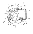
- FIG. 2 is a plan view of the motor unit according to the embodiment as seen from above.
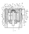
- FIG. 3 is a view showing an internal structure of the motor unit of the embodiment, and is a sectional view taken along line III-III of FIG.
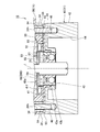
- FIG. 4 is a diagram showing an internal structure of a lower portion of the motor unit according to the embodiment, and is an enlarged view of a main part of FIG. 3.
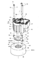
- FIG. 5 is an exploded perspective view of the housing of the motor unit according to the embodiment.
- FIG. 1 is a perspective view showing the appearance of the motor unit 10 of this embodiment.
- FIG. 2 is a plan view of the motor unit 10 of the present embodiment as seen from above.
- FIG. 3 is a view showing the internal structure of the motor unit 10 of the present embodiment, which is a sectional view taken along the line III-III of FIG.
- the motor unit 10 includes a motor body 20, a housing 11, a controller 50 (see FIG. 3), and an upper cover 60.
- the direction parallel to the central axis J is simply referred to as “axial direction” or “vertical direction”
- the radial direction around the central axis J is simply referred to as “radial direction”
- the circumferential direction about the central axis J that is, the circumference of the central axis J is simply referred to as “circumferential direction”.
- “plan view” means a state viewed from the axial direction.
- the upper side of FIG. 3 in the axial direction along the central axis J is simply referred to as “upper side”
- the lower side is simply referred to as “lower side”.
- the vertical direction does not indicate the posture of the motor unit 10 and the positional relationship and direction of each part when it is incorporated in an actual device.
- the scale and the number of each structure may be different from the actual structure.
- the motor body 20 has a rotor 25 and a stator 21.
- the rotor 25 rotates about a central axis J extending along the up-down direction.
- the rotor 25 has a shaft 26, a rotor core 27, and a plurality of magnets 28.
- the shaft 26 is arranged along the central axis J extending in the vertical direction.
- the shaft 26 has a columnar shape extending in the vertical direction.
- the shaft 26 is made of metal and is made of an iron-based alloy (steel material).
- the shaft 26 is rotatably supported by the upper bearing 29A and the lower bearing 29B about the central axis J.
- An upper bearing 29 ⁇ /b>A that supports the upper portion of the shaft 26 is held by the motor housing 30 of the housing 11.
- the upper bearing 29A is located above the stator 21.
- a lower bearing 29B that supports the lower portion of the shaft 26 is held by the gear housing 40.
- the lower bearing 29B is located below the stator 21.
- the lower bearing 29B is composed of a one-way clutch 89, as will be described later in detail.
- the rotor core 27 has a columnar shape extending in the vertical direction.
- the rotor core 27 has a fixing hole portion 27a that penetrates the rotor core 27 in the vertical direction.
- the shape of the fixing hole portion 27a viewed in the up-down direction is a circular shape with the central axis J as the center.
- the shaft 26 is passed through the fixing hole portion 27a.
- the shaft 26 is fixed to the rotor core 27 by press fitting or adhesion.
- the shaft 26 may be fixed to the rotor core 27 via a resin member or the like. As a result, the rotor core 27 is fixed to the shaft 26.
- the plurality of magnets 28 are fixed to the rotor core 27.
- the magnet 28 may be fixed inside the rotor core 27 or may be fixed on the outer peripheral surface.
- the plurality of magnets 28 are arranged along the circumferential direction.
- the magnets 28 that are adjacent to each other in the circumferential direction are arranged such that their magnetic poles facing in the radial direction are reversed.
- the plurality of magnets 28 are arranged at equal intervals along the circumference along the circumference.
- the stator 21 is located radially outside the rotor 25.
- the stator 21 mainly has a stator core 22 and a coil 24.
- the stator core 22 has a tubular core back portion 23a centered on the central axis J and a plurality of teeth portions 23b extending inward in the radial direction from the core back portion 23a.
- the core back portion 23a has a core outer peripheral surface 22a that faces outward in the radial direction.
- the core outer peripheral surface 22a extends along the circumferential direction. As will be described later, the core outer peripheral surface 22a of the core back portion 23a is exposed from the motor housing 30.
- a plurality of teeth portions 23b are provided at equal intervals in the circumferential direction around the central axis J.
- the coil 24 is wound around the teeth portion 23b via an insulating insulator.
- the housing 11 has a motor housing (first member) 30 and a gear housing (second member) 40.
- the motor housing 30 houses the motor body 20.
- the housing 11 houses the motor body 20.
- the gear housing 40 accommodates a drive gear (not shown).
- "accommodating" is a concept including not only the case where the whole object enters inside but also surrounding at least a part of the object from the periphery.
- the motor housing 30 has a motor holding portion 32, a bearing holder 33, and a collar 34.
- the motor holding portion 32 is made of resin. More specifically, the insert-molded product includes the stator 21, the bearing holder 33, and the collar 34. In other words, the motor holding portion 32 is the resin portion 32p that holds the stator 21, the bearing holder 33, and the collar 34. As shown in FIGS. 1 to 3, the motor holding portion 32 has a columnar portion 35, a bulging portion 36, and a housing expansion portion 37. The columnar portion 35, the bulging portion 36, and the housing expansion portion 37 are a single member.
- the columnar portion 35 has a columnar shape extending in the vertical direction.
- the columnar portion 35 has substantially the same outer diameter dimension as the stator 21.
- the core outer peripheral surface 22 a located on the outer peripheral portion of the stator 21 may be exposed on the outer peripheral surface of the columnar portion 35.
- the columnar portion 35 has a plate-shaped portion 35a and a filling portion 35b. That is, the motor housing 30 has the plate-shaped portion 35a and the filling portion 35b.
- the plate-shaped portion 35a is provided above the stator 21.
- the plate-shaped portion 35a is a disk-shaped portion that is orthogonal to the central axis J.
- a bearing holding recess 35h is provided on the lower surface of the plate-shaped portion 35a.
- the bearing holding recess 35h is located at the center of the plate-shaped portion 35a.
- the bearing holding recess 35h is recessed upward.
- the bearing holder 33 is held in the bearing holding recess 35h.
- the plate-shaped portion 35a holds the upper bearing 29A via the bearing holder 33.
- the bearing holder 33 is provided in the bearing holding recess 35h of the motor holding portion 32.
- the bearing holder 33 is made of metal.
- the bearing holder 33 has a holder cylinder portion 33a and a lid portion 33b.
- the holder cylinder portion 33a and the lid portion 33b are a single member.
- the holder tubular portion 33a has a cylindrical shape extending in the vertical direction.
- An upper bearing 29A is arranged on the radially inner side of the holder tubular portion 33a.
- the lid portion 33b is a disc-shaped member that extends in the vertical direction and covers the upper end portion of the holder tubular portion 33a.
- the filling portion 35b surrounds the tooth portion 23b and the coil 24 in the stator 21, and is provided between the tooth portion 23b and the coil 24 that are adjacent to each other in the circumferential direction.
- the filling portion 35b extends downward from the plate-shaped portion 35a.
- the bulging portion 36 is provided on the outer peripheral portion of the columnar portion 35.
- the bulging portion 36 projects radially outward from the outer peripheral surface of the columnar portion 35.
- the bulging portions 36 are provided at a plurality of places at intervals in the circumferential direction. In the present embodiment, the bulging portions 36 are provided at three places spaced apart in the circumferential direction. As shown in FIG. 3, the bulges 36 are continuous in the vertical direction.
- Each bulging portion 36 has a hole portion 36h extending along the up-down direction. That is, the resin portion 32p is provided with the hole portion 36h.
- the housing extension portion 37 is provided on the outer peripheral portion of the upper portion of the motor holding portion 32 (more specifically, the columnar portion 35).
- the housing extension portion 37 is provided only in a part in the vertical direction with respect to the columnar portion 35.
- the housing expansion part 37 is provided between two bulging parts 36 adjacent to each other in the circumferential direction.
- the housing extension portion 37 extends radially outward from the upper portion of the columnar portion 35.
- the collar 34 is arranged in the hole 36h of the bulging portion 36.
- the collar 34 is made of metal and has a cylindrical shape extending in the vertical direction.
- the collar 34 is provided with a bolt insertion hole 34h penetrating in the vertical direction.
- the collar 34 is molded in the bulging portion 36.
- the collar 34 is exposed on the upper surface 36a and the lower surface 36b of the bulging portion 36.
- the vertical length of the collar 34 is slightly larger than the vertical thickness of the bulging portion 36 (the vertical spacing between the upper surface 36a and the lower surface 36b).
- the upper end portion of the collar 34 projects upward with respect to the upper surface 36a of the bulging portion 36.
- the lower end portion of the collar 34 projects downward with respect to the lower surface 36b of the bulging portion 36.
- FIG. 4 is a diagram showing an internal structure of a lower portion of the motor unit 10 of the present embodiment, and is an enlarged view of a main part of FIG.
- FIG. 5 is an exploded perspective view of the housing 11 of the motor unit 10 of this embodiment.
- the gear housing 40 is provided below the motor housing 30.
- the gear housing 40 has a base portion (outer ring holding portion) 41 and an outer cylinder portion 42.
- the base portion 41 and the outer cylinder portion 42 are a single member.
- the gear housing 40 is made of metal and made of aluminum alloy.
- the base 41 is a disc-shaped portion that intersects in the vertical direction.
- a bearing holding hole 43 is provided at the center of the base 41.
- the bearing holding hole 43 extends vertically through the base 41.
- the inner diameter of the upper portion 43a of the bearing holding hole 43 is larger than that of the lower portion 43b.
- On the inner peripheral surface of the upper portion 43a of the bearing holding hole 43 there is provided a housing recess 43d that is enlarged radially outward of the inner peripheral surface of the lower portion 43b.
- the accommodation recess 43d is a space that opens upward.
- the outer cylinder portion 42 is a cylindrical shape extending in the vertical direction, and extends downward from the outer peripheral portion of the base portion 41 in the vertical direction. As shown in FIG. 4, a gear accommodating recess 44 is provided inside the outer cylinder portion 42 in the radial direction. The gear housing recess 44 opens below the gear housing 40.
- a plurality of screw holes 46 are provided on the upper surface of the gear housing 40.
- Each screw hole 46 is opposed to the bolt insertion hole 34h of the collar 34 provided in the bulging portion 36 of the motor housing 30 in the vertical direction.
- a female screw groove is provided on the inner peripheral surface of each screw hole 46.
- a holding member 90 is provided above the base 41 of the gear housing 40.
- the holding member 90 holds the one-way clutch 89 that constitutes the lower bearing 29B.
- the one-way clutch 89 has an outer ring 81, an inner ring 82, a plurality of steel balls 83, and a clutch portion 84.
- the outer ring 81, the inner ring 82, the steel balls 83, and the clutch portion 84 are each made of metal and made of an iron-based alloy (steel material).
- the inner ring 82 has a cylindrical shape extending in the vertical direction.
- the shaft 26 is press-fitted inside the inner ring 82 in the radial direction.
- the outer ring 81 is arranged radially outward of the inner ring 82 with a gap.
- the outer ring 81 has a cylindrical shape extending in the vertical direction.
- the plurality of steel balls 83 are arranged between the outer peripheral surface of the inner ring 82 and the inner peripheral surface of the outer ring 81.
- the one-way clutch 89 having the ball bearing mechanism using the steel balls 83 as rolling elements is shown.
- the one-way clutch may have a needle bearing mechanism having a cylindrical body as a rolling element, or may have a structure without any bearing mechanism, that is, a structure having only a one-way clutch function. Good.
- the clutch portion 84 is arranged above the steel ball 83 and between the outer peripheral surface of the inner ring 82 and the inner peripheral surface of the outer ring 81.
- the clutch portion 84 causes a slip between the inner ring 82 into which the shaft 26 is press fitted and the outer ring 81.
- the inner ring 82 becomes rotatable with respect to the outer ring 81, and the shaft 26 becomes rotatable around the axis.
- the one-way clutch 89 (lower bearing 29B) functions as a bearing like a normal bearing.
- the clutch portion 84 is provided between the inner ring 82 and the outer ring 81.
- the inner ring 82 is locked with respect to the outer ring 81, and rotation of the inner ring 82 about its axis is restricted.
- the one-way clutch 89 blocks input of external force from the drive gear side, which tends to rotate the shaft 26 in the reverse direction.
- the holding member 90 has a tubular portion 91 and a flange portion 92.
- the tubular portion 91 and the flange portion 92 are a single member.
- the tubular portion 91 has a cylindrical shape extending in the vertical direction.
- the tubular portion 91 is inserted inside the housing recess 43d of the bearing holding hole 43 in the radial direction.
- the tubular portion 91 is housed in the housing recess 43d.
- the outer ring 81 of the one-way clutch 89 is press-fitted inside the tubular portion 91 in the radial direction.
- the holding member 90 has the tubular portion 91 into which the outer ring 81 is press fitted.
- the holding member 90 is connected to the outer ring 81.
- the flange portion 92 extends radially outward from the upper end of the tubular portion 91.
- the flange portion 92 extends along the upper surface 41f of the base portion 41.
- the upper surface 41f is a plane orthogonal to the central axis J. That is, the flange portion 92 extends along a plane orthogonal to the central axis J.
- the flange portion 92 is sandwiched between the motor holding portion 32 of the motor housing 30 and the gear housing 40.
- the holding member 90 is fixed to the housing 11. That is, the housing 11 includes the motor housing 30 and the gear housing 40 that hold the holding member 90 by sandwiching the flange portion 92 from the vertical direction.
- the flange portion 92 has extended flange portions 93 at a plurality of circumferential positions.
- the extension flange portions 93 extend outward from the flange portions 92 in the radial direction.
- the extension flange portion 93 is sandwiched between the bulging portion 36 of the motor housing 30 and the outer peripheral portion of the base portion 41 of the gear housing 40. More specifically, the extension flange portion 93 is sandwiched between the collar 34 and the outer peripheral portion of the base portion 41 of the gear housing 40.
- Each extension flange portion 93 has a bolt insertion hole 94.
- the bolt insertion hole 94 penetrates the extending flange portion 93 in the vertical direction.
- the bolt insertion hole 94 communicates with the bolt insertion hole 34h of the collar 34 provided in the bulging portion 36 in the vertical direction.
- the bolt 70 described below is inserted into the bolt insertion hole 94.
- the holding member 90 is made of a material having a linear expansion coefficient closer to that of the outer ring 81 made of an iron-based alloy than the base 41 of the gear housing 40 made of an aluminum alloy.
- the holding member 90 is made of the same material as the outer ring 81 of the one-way clutch 89.
- the holding member 90 is made of an iron-based alloy (steel material) of the same type as the outer ring 81.
- the base 41 made of an aluminum alloy is made of a different material from the outer ring 81 made of an iron-based alloy. Such a holding member 90 is formed into a predetermined shape by press working.
- control unit 50 is located above the motor body 20.
- the control unit 50 controls the rotation of the rotor 25.
- the control unit 50 has a control board 51.
- the control board 51 has a flat plate shape, and is arranged above the plate-like portion 35a of the motor housing 30 with a gap.
- the control board 51 is provided parallel to the upper surface of the plate-shaped portion 35a.
- a plurality of electronic components are mounted on the upper and lower surfaces of the control board 51.
- the control board 51 has a main body portion 51a and an extension portion 51b.
- the main body portion 51a and the expansion portion 51b are a single member.
- the main body portion 51 a is provided above the columnar portion 35 of the motor holding portion 32 of the motor housing 30.
- the motor body 20 and the bearing holder 33 face the control unit 50 in the vertical direction.
- the expansion portion 51b extends radially outward from the main body portion 51a.
- the expansion portion 51b projects radially outward with respect to the columnar portion 35 of the motor housing 30.
- the extension portion 51b is arranged in a region overlapping with the housing extension portion 37 when viewed from above and below.
- the extension part 51b of the control part 50 is provided with a connector part 53 extending downward. As shown in FIGS. 1 and 3, at least a part of the connector portion 53 projects downward from the housing extension portion 37.
- An external connector (not shown) that externally supplies electric power and inputs/outputs control signals is detachably connected to the connector portion 53.
- the upper cover 60 faces the motor housing 30 in the vertical direction.
- the upper cover 60 covers the upper part of the motor housing 30.
- the upper cover 60 has a cover base portion 61 and a cover fixing portion 62.
- the cover base portion 61 and the cover fixing portion 62 are a single member.
- the upper cover 60 is made of metal.
- the cover base 61 covers the main body 51a and the extension 51b of the controller 50 from above.
- the cover base 61 has a flat plate shape orthogonal to the central axis J and covers the columnar portion 35 of the motor housing 30 and the upper portion of the housing extension portion 37.
- a part of the cover base 61 is provided with a protruding cover part 61b protruding upward.
- the electronic components provided in the control unit 50 electronic components, wirings, and the like that have a large protrusion size upward from the control board 51 are provided below the protrusion cover unit 61b in order to avoid interference with the upper cover 60. ..
- the cover fixing portions 62 are provided at a plurality of locations on the outer peripheral portion of the cover base portion 61 that are spaced apart in the circumferential direction.
- the cover fixing portion 62 projects radially outward from the cover base portion 61.
- the cover fixing portion 62 faces the bulging portion 36 of the motor housing 30 in the vertical direction.
- the upper surface of the cover fixing portion 62 is located below the upper surface of the cover base portion 61.
- the cover fixing portion 62 is provided with a fixing hole 64 that vertically penetrates the upper cover 60.
- the fixing hole 64 vertically overlaps with the bolt insertion hole 34h of the collar 34 provided in the bulging portion 36 and the bolt insertion hole 94 of the holding member 90.
- the upper cover 60 is fixed to the motor housing 30 with bolts 70.
- the shaft portion 71 of the bolt 70 passes through the fixing holes 64 provided in the plurality of cover fixing portions 62, the bolt insertion hole 34h of the collar 34, the bolt insertion hole 94 of the holding member 90, and the screw hole of the gear housing 40. It is fastened to 46.
- the axial force of the bolt 70 is transmitted between the cover fixing portion 62 of the metallic upper cover 60 and the metallic gear housing 40 via the metallic collar 34. This prevents the axial force of the bolt 70 from excessively acting on the bolt insertion hole 34h.
- the head 72 of the bolt 70 contacts the upper surface of the cover fixing portion 62 of the upper cover 60 while the bolt 70 is fastened. In this state, the upper end surface 72t of the head 72 of the bolt 70 is located below the uppermost surface 61t of the cover base 61 of the upper cover 60. In the present embodiment, the uppermost surface 61t of the cover base portion 61 is the upper surface of the protruding cover portion 61b.
- the upper cover 60 contacts the motor housing 30 and is directly fixed to the motor housing 30. Specifically, outside the controller 50, the upper surface of the motor housing 30 and the lower surface of the upper cover 60 are in direct contact with each other in the vertical direction.
- the motor unit 10 has a seal structure 80 that suppresses moisture from entering between the motor housing 30 and the upper cover 60.
- the seal structure 80 is provided along the inner peripheral edge of a region where the upper surface of the motor housing 30 and the lower surface of the upper cover 60 face each other in the vertical direction.
- the seal structure 80 is provided in an annular shape so as to surround the entire circumference of the control unit 50 when viewed in the vertical direction.
- the plurality of bolts 70 are arranged outside the seal structure 80 when viewed in the vertical direction.
- the seal structure 80 is composed of a gasket member formed in a predetermined shape in advance and a cured liquid gasket.
- the holding member 90 connected to the outer ring 81 is made of the same material as the outer ring 81. Since the outer ring 81 and the holding member 90 are made of the same material, the difference between the linear expansion coefficient of the outer ring 81 and the linear expansion coefficient of the holding member 90 can be reduced. As a result, the volume change amounts of the holding member 90 and the outer ring 81 can be made closer to each other when the temperature of the usage environment of the motor unit 10 rises or is processed. Therefore, the gap between the holding member 90 and the outer ring 81 can be suppressed from expanding.
- the outer ring 81 and the holding member 90 may be connected to each other by another structure.
- the outer ring 81 and the holding member 90 may be connected by spline fitting.
- the outer race 81 and the holding member 90 from the same material, it is possible to suppress the expansion of the gap for spline fitting. As a result, rattling of the spline fitting can be suppressed, and the reliability of the connection between the one-way clutch 89 and the housing 11 can be improved.
- the holding member 90 has the tubular portion 91 into which the outer ring 81 is press fitted.
- the one-way clutch 89 can be assembled to the holding member 90 by press fitting, and the assembly process can be simplified.
- the housing 11 has the base portion 41 in which the accommodation recess 43d in which the tubular portion 91 is accommodated is provided.
- the base 41 is composed of an outer ring 81 and a different material. As a result, the material of the base portion 41 of the housing 11 can be selected regardless of the material of the one-way clutch 89, so that the degree of freedom in design is increased.
- the base 41 is made of an aluminum alloy.
- Aluminum alloys are lightweight and can be manufactured by die casting. Therefore, even if the housing 11 having the base portion 41 has a complicated shape, it can be manufactured relatively inexpensively.
- the housing 11 has the motor housing 30 and the gear housing 40 that hold the holding member 90 by sandwiching the flange portion 92 from the vertical direction.
- the flange portion 92 of the holding member 90 is sandwiched between the motor housing 30 and the gear housing 40 in the vertical direction, so that the rotation of the holding member 90 can be suppressed with a simple structure.
- the motor housing 30 and the gear housing 40 are fixed to each other by the bolts 70 extending in the vertical direction, and the flange portion 92 is provided with the bolt insertion holes 94 into which the bolts 70 are inserted. Accordingly, the holding member 90 can be fixed by using the bolt 70 that fixes the motor housing 30 and the gear housing 40. Moreover, since the bolt 70 is passed through the bolt insertion hole 94, the rotation of the holding member 90 can be more reliably suppressed.
- the holding member 90 and the outer ring 81 are made of an iron-based alloy.
- the iron-based alloy has high rigidity and is relatively inexpensive, and is suitable for realizing a structure that suppresses idling of the one-way clutch 89.
- the holding member 90 is formed by press working. Thereby, the holding member 90 can be manufactured at low cost.
- the use of the motor unit of the above-described embodiment and its modification is not particularly limited.
- the motor unit of the above-described embodiment and its modification is mounted on, for example, an electric pump, an electric power steering, or the like.
- the lower bearing 29B is configured by the one-way clutch 89 in the above-described embodiment, the lower bearing and the one-way clutch 89 may be separately provided.
- SYMBOLS 10 Motor unit, 11... Housing, 20... Motor main body, 21... Stator, 25... Rotor, 30... Motor housing (1st member), 40... Gear housing (2nd member), 41... Base part (outer ring holding part) , 43d... Receiving recess, 70... Bolt, 89... One-way clutch, 81... Outer ring, 82... Inner ring, 90... Holding member, 91... Cylindrical part, 92... Flange part, 94... Bolt insertion hole, J... Central shaft
Landscapes
- Engineering & Computer Science (AREA)
- General Engineering & Computer Science (AREA)
- Mechanical Engineering (AREA)
- Power Engineering (AREA)
- Motor Or Generator Frames (AREA)
- Connection Of Motors, Electrical Generators, Mechanical Devices, And The Like (AREA)
- Power Steering Mechanism (AREA)
Abstract
本発明のモータユニットの一つの態様は、上下方向に沿って延びる中心軸を中心として回転するロータ、および前記ロータの径方向外側に位置するステータを有するモータ本体と、内輪および外輪を有し、前記内輪が前記ロータに連結されるワンウェイクラッチと、前記モータ本体を収容するハウジングと、前記ハウジングに固定されるとともに前記外輪に連結される保持部材と、を備え、前記保持部材は、前記外輪と同種材料から構成される。
Description
本発明は、モータユニットに関する。
本出願は、2019年2月13日に提出された日本特許出願第2019-023886号に基づいている。本出願は、当該出願に対して優先権の利益を主張するものである。その内容全体は、参照されることによって本出願に援用される。
ロータおよびステータを有するモータにおいて、ロータのシャフトは、軸受により回転自在に支持されている。モータは、シャフトの回転を外部に伝達することで、駆動対象となる機器等を駆動する。このようなモータには、シャフトの逆回転を抑制するためにワンウェイクラッチが設けられる場合がある。例えば、特許文献1には、ワンウェイクラッチが、シャフト(出力シャフト)と、駆動対象となるオイルポンプのポンプカバーとの間に設けられる構成が開示されている。
国際公開第2013/099505号
このようなモータは、例えば、オイル温度が常温から150℃程度まで上昇するオイルポンプに使用される場合がある。ワンウェイクラッチの材料には、軸受等と同様の、鉄系合金(鋼)が主に用いられる。これに対し、ワンウェイクラッチを支持するポンプカバー等のハウジングは、軽量化のため、アルミニウム合金が用いられることが多い。鉄系合金と、アルミニウム合金とでは、線膨張係数が大きく異なる。このため、ハウジングとワンウェイクラッチとの間で隙間が拡大して空転が生じる虞がある。
本発明は、上記事情に鑑みて、ワンウェイクラッチとハウジングとの間の連結の信頼性を高めることができるモータユニットを提供することを目的の一つとする。
本発明のモータユニットの一つの態様は、上下方向に沿って延びる中心軸を中心として回転するロータ、および前記ロータの径方向外側に位置するステータを有するモータ本体と、内輪および外輪を有し、前記内輪が前記ロータに連結されるワンウェイクラッチと、前記モータ本体を収容するハウジングと、前記ハウジングに固定されるとともに前記外輪に連結される保持部材と、を備え、前記保持部材は、前記外輪と同種材料から構成される。
本発明の一つの態様によれば、ワンウェイクラッチとハウジングとの間の連結の信頼性を高めることができるモータユニットが提供される。
図1は、本実施形態のモータユニット10の外観を示す斜視図である。図2は、本実施形態のモータユニット10を上方から見た平面図である。図3は本実施形態のモータユニット10の内部構造を示す図であり、図2のIII-III断面図である。図1~図3に示すように、モータユニット10は、モータ本体20と、ハウジング11と、制御部50(図3参照)と、上カバー60と、を備える。
以下の説明においては、中心軸J(図3参照)に平行な方向を単に「軸方向」又は「上下方向」と呼び、中心軸Jを中心とする径方向を単に「径方向」と呼び、中心軸Jを中心とする周方向、すなわち、中心軸Jの軸周りを単に「周方向」と呼ぶ。さらに、以下の説明において、「平面視」とは、軸方向から視た状態を意味する。また、本明細書では、中心軸Jに沿った軸方向における図3の上側を単に「上側」と呼び、下側を単に「下側」と呼ぶ。なお、上下方向は、実際の機器に組み込まれたときのモータユニット10の姿勢および各部位置関係や方向を示すものではない。また、以下の図面においては、各構成をわかりやすくするために、実際の構造と各構造における縮尺や数等を異ならせる場合がある。
図3に示すように、モータ本体20は、ロータ25と、ステータ21と、を有する。ロータ25は、上下方向に沿って延びる中心軸Jを中心として回転する。ロータ25は、シャフト26と、ロータコア27と、複数のマグネット28と、を有する。
シャフト26は、上下方向に延びる中心軸Jに沿って配置される。シャフト26は、上下方向に延びる円柱状である。シャフト26は、金属製で、鉄系合金(鋼材)からなる。シャフト26は、上部ベアリング29Aおよび下部ベアリング29Bにより、中心軸J周りに回転可能に支持される。シャフト26の上部を支持する上部ベアリング29Aは、ハウジング11のモータハウジング30に保持されている。上部ベアリング29Aは、ステータ21の上側に位置する。シャフト26の下部を支持する下部ベアリング29Bは、ギヤハウジング40に保持されている。下部ベアリング29Bは、ステータ21の下側に位置する。本実施形態において、下部ベアリング29Bは、後に詳述するように、ワンウェイクラッチ89により構成される。
図3に示す様に、ロータコア27は、上下方向に延びる柱状である。ロータコア27は、ロータコア27を上下方向に貫通する固定孔部27aを有する。固定孔部27aの上下方向に沿って視た形状は、中心軸Jを中心とする円形状である。固定孔部27aには、シャフト26が通される。シャフト26は、ロータコア27に対して、圧入や接着などによって固定される。また、シャフト26は、ロータコア27に対して、樹脂部材などを介して固定してもよい。これにより、ロータコア27は、シャフト26に固定される。
複数のマグネット28は、ロータコア27に固定される。マグネット28は、ロータコア27の内部に固定されていても外周面に固定されていてもよい。複数のマグネット28は、周方向に沿って並ぶ。周方向において互いに隣り合うマグネット28同士は、径方向を向く磁極が互いに反転されて配置されている。複数のマグネット28は、周方向に沿って一周に亘って等間隔に配置される。
ステータ21は、ロータ25の径方向外側に位置する。ステータ21は、ステータコア22と、コイル24と、を主に有する。
ステータコア22は、中心軸Jを中心とする筒状のコアバック部23aと、コアバック部23aから径方向内側に延びる複数のティース部23bと、を有する。図1に示すように、コアバック部23aは、径方向外側を向くコア外周面22aを有する。コア外周面22aは、周方向に沿って延びる。後述するように、コアバック部23aのコア外周面22aは、モータハウジング30から露出する。
ティース部23bは、中心軸J周りの周方向に等間隔をあけて複数設けられる。コイル24は、絶縁性のインシュレータを介してティース部23bに巻き付けられる。
ハウジング11は、モータハウジング(第1部材)30と、ギヤハウジング(第2部材)40と、を有する。モータハウジング30は、モータ本体20を収容する。これにより、ハウジング11は、モータ本体20を収容する。ギヤハウジング40は、図示略のドライブギヤを収容する。なお、本明細書において、「収容」とは、対象物の全体が内部に入る場合のみならず、対象物の少なくとも一部を周囲から囲むことを含む概念である。
モータハウジング30は、モータ保持部32と、ベアリングホルダ33と、カラー34と、を有する。
モータ保持部32は、樹脂製である。より詳細には、ステータ21、ベアリングホルダ33およびカラー34を含むインサート成形品である。換言すると、モータ保持部32は、ステータ21、ベアリングホルダ33およびカラー34を保持する樹脂部32pである。図1~図3に示すように、モータ保持部32は、柱状部35と、膨出部36と、ハウジング拡張部37と、を有する。柱状部35と、膨出部36と、ハウジング拡張部37とは、単一の部材である。
柱状部35は、上下方向に延びる円柱状である。柱状部35は、ステータ21とほぼ同じ外径寸法を有している。図1に示すように、柱状部35の外周面には、ステータ21の外周部に位置するコア外周面22aが露出していてもよい。図3に示すように、柱状部35は、板状部35aと、充填部35bと、を有する。すなわち、モータハウジング30は、板状部35aと充填部35bとを有する。
板状部35aは、ステータ21の上側に設けられる。板状部35aは、中心軸Jと直交する円板状の部分である。図3に示すように、板状部35aの下面には、ベアリング保持凹部35hが設けられる。ベアリング保持凹部35hは、板状部35aの中央部に位置する。ベアリング保持凹部35hは、上方に窪む。ベアリング保持凹部35hには、ベアリングホルダ33を保持する。板状部35aは、ベアリングホルダ33を介して上部ベアリング29Aを保持する。
図3に示すように、ベアリングホルダ33は、モータ保持部32のベアリング保持凹部35hに設けられる。ベアリングホルダ33は、金属製である。ベアリングホルダ33は、ホルダ筒部33aと、蓋部33bと、を有する。ホルダ筒部33aと、蓋部33bとは、単一の部材である。ホルダ筒部33aは、上下方向に延びる円筒状である。ホルダ筒部33aの径方向内側には、上部ベアリング29Aが配置される。蓋部33bは、上下方向に交差して延びる円板状で、ホルダ筒部33aの上端部を覆う部分である。
充填部35bは、ステータ21において、ティース部23bおよびコイル24を囲むとともに、周方向で互いに隣り合うティース部23bおよびコイル24の間に設けられる。
充填部35bは、板状部35aから下方に延びる。
充填部35bは、板状部35aから下方に延びる。
図1~図3に示すように、膨出部36は、柱状部35の外周部に設けられる。膨出部36は、柱状部35の外周面から径方向外側に突出する。膨出部36は、周方向に間隔をあけて複数個所に設けられる。本実施形態において、膨出部36は、周方向に間隔をあけた3個所に設けられる。図3に示すように、各膨出部36は、上下方向に連続する。各膨出部36は、上下方向に沿って延びる孔部36hを有する。すなわち、樹脂部32pには、孔部36hが設けられる。
図1、図2に示すように、ハウジング拡張部37は、モータ保持部32(より詳細には、柱状部35)の上部の外周部に設けられる。ハウジング拡張部37は、柱状部35に対し、上下方向の一部のみに設けられる。ハウジング拡張部37は、周方向で互いに隣り合う2つの膨出部36の間に設けられる。ハウジング拡張部37は、柱状部35の上部から径方向外側に延びる。
図3に示すように、カラー34は、膨出部36の孔部36h内に配置される。カラー34は、金属製で、上下方向に延びる筒状である。カラー34には、上下方向に貫通するボルト挿通孔34hが設けられる。カラー34は、膨出部36内にモールドされている。カラー34は、膨出部36の上面36aおよび下面36bに露出する。カラー34は、上下方向の長さが、膨出部36の上下方向の厚み(上面36aと下面36bとの上下方向における間隔寸法)よりも僅かに大きい。カラー34の上端部は、膨出部36の上面36aに対し上側に突出する。カラー34の下端部は、膨出部36の下面36bに対し下側に突出する。後述するボルト70を締結したときに、上カバー60とギヤハウジング40とが、カラー34の上下に突き当たり、ボルト70の軸力が、樹脂製のモータ保持部32に過大に作用することが抑えられる。
図4は、本実施形態のモータユニット10の下部の内部構造を示す図であり、図3の要部拡大図である。図5は、本実施形態のモータユニット10のハウジング11の展開斜視図である。図4、図5に示すように、ギヤハウジング40は、モータハウジング30の下側に設けられる。ギヤハウジング40は、基部(外輪保持部)41と、外筒部42と、を有する。基部41と外筒部42とは、単一の部材である。ギヤハウジング40は、金属製で、アルミニウム合金から構成される。
基部41は、上下方向に交差する円板状の部分である。基部41の中央部には、ベアリング保持孔43が設けられる。ベアリング保持孔43は、基部41を上下方向に貫通する。ベアリング保持孔43の上部43aは、下部43bに対し、内径が拡大している。ベアリング保持孔43の上部43aの内周面には、下部43bの内周面よりも径方向外側に拡大した収容凹部43dが設けられる。収容凹部43dは、上方に向かって開口する空間部である。
外筒部42は、上下方向に伸びる円筒状で、基部41の外周部から上下方向の下方に延びる。図4に示すように、外筒部42の径方向内側には、ギヤ収容凹部44が設けられる。ギヤ収容凹部44は、ギヤハウジング40の下方に開口する。
図4および図5に示すように、ギヤハウジング40の上面には、複数のネジ穴46が設けられている。各ネジ穴46は、モータハウジング30の膨出部36に設けられたカラー34のボルト挿通孔34hに対し、上下方向で対向する。各ネジ穴46の内周面には、雌ネジ溝が設けられる。
ギヤハウジング40の基部41の上側には、保持部材90が設けられる。保持部材90は、下部ベアリング29Bを構成するワンウェイクラッチ89を保持する。ワンウェイクラッチ89は、外輪81と、内輪82と、複数の鋼球83と、クラッチ部84と、を有する。外輪81、内輪82、鋼球83およびクラッチ部84は、それぞれ、金属製で、鉄系合金(鋼材)から構成される。
内輪82は、上下方向に延びる円筒状である。内輪82の径方向内側には、シャフト26が圧入される。これにより、内輪82は、ロータ25に連結される。外輪81は、内輪82の径方向外側に間隔をあけて配置される。外輪81は、上下方向に延びる円筒状である。複数の鋼球83は、内輪82の外周面と外輪81の内周面との間に配置される。本実施形態では、鋼球83を転動体として使用するボールベアリング機構を有するワンウェイクラッチ89を示した。しかしながら、ワンウェイクラッチは、転動体として円柱体を有するニードルベアリング機構を有していてもよく、また、如何なるベアリング機構をも有していない構造、すなわちワンウェイクラッチ機能のみを有した構造であってもよい。
クラッチ部84は、鋼球83の上側で内輪82の外周面と外輪81の内周面との間に配置される。クラッチ部84は、モータ本体20の作動時にシャフト26が軸周りの所定の第一方向に回転する場合、シャフト26が圧入された内輪82と、外輪81との間ですべりを生じる。これにより、外輪81に対して内輪82が回転自在となり、シャフト26が軸周りに回転自在となる。この状態で、ワンウェイクラッチ89(下部ベアリング29B)は、通常のベアリングと同様に軸受として機能する。クラッチ部84は、図示略のドライブギヤ側から、シャフト26を所定の第一方向と反対向きの第二方向に逆回転させようとする外力が入力された場合、内輪82と外輪81との間で摩擦抵抗を増大させる。これにより、外輪81に対して内輪82がロックされ、内輪82の軸周りの回転が拘束される。この状態で、ワンウェイクラッチ89は、ドライブギヤ側からシャフト26を逆回転させようとする外力の入力を阻止する。
図4、図5に示すように、保持部材90は、筒状部91と、フランジ部92と、を有する。筒状部91とフランジ部92とは、単一の部材である。
筒状部91は、上下方向に延びる円筒状である。筒状部91は、ベアリング保持孔43の収容凹部43dの径方向内側に挿入される。筒状部91は、収容凹部43dに収容される。筒状部91の径方向内側に、ワンウェイクラッチ89の外輪81が圧入される。これにより、保持部材90は、外輪81が圧入される筒状部91を有する。保持部材90は、外輪81に連結される。
フランジ部92は、筒状部91の上端から径方向外側に延びる。フランジ部92は、基部41の上面41fに沿う。上面41fは、中心軸Jと直交する平面である。つまり、フランジ部92は、中心軸Jと直交する平面に沿って延びる。フランジ部92は、モータハウジング30のモータ保持部32とギヤハウジング40との間に挟み込まれる。これにより、保持部材90は、ハウジング11に固定される。すなわち、ハウジング11は、フランジ部92を上下方向から挟み込んで保持部材90を保持するモータハウジング30およびギヤハウジング40を有する。
フランジ部92は、周方向複数個所に、延出フランジ部93を有する。延出フランジ部93は、それぞれフランジ部92から径方向外側に延びる。延出フランジ部93は、モータハウジング30の膨出部36と、ギヤハウジング40の基部41の外周部との間に挟み込まれる。より詳細には、延出フランジ部93は、カラー34とギヤハウジング40の基部41の外周部との間に挟み込まれる。ボルト70を締結した状態で、各延出フランジ部93の上面は、カラー34の下面と接触し、各延出フランジ部93の下面は、基部41の外周部の上面と接する。各延出フランジ部93は、ボルト挿入孔94を有する。ボルト挿入孔94は、延出フランジ部93を上下方向に貫通する。ボルト挿入孔94は、膨出部36に設けられたカラー34のボルト挿通孔34hに上下方向で連通する。ボルト挿入孔94は、後述するボルト70が挿入される。
保持部材90は、アルミニウム合金からなるギヤハウジング40の基部41よりも、鉄系合金からなる外輪81に、線膨張係数が近い材料から構成される。保持部材90は、ワンウェイクラッチ89の外輪81と同種材料から構成される。保持部材90は、外輪81と同種の鉄系合金(鋼材)から構成される。アルミニウム合金からなる基部41は、鉄系合金からなる外輪81と異種材料から構成される。このような保持部材90は、プレス加工により所定形状に成形される。
図3に示すように、制御部50は、モータ本体20の上側に位置する。制御部50は、ロータ25の回転を制御する。制御部50は、制御基板51を有する。制御基板51は、平板状で、モータハウジング30の板状部35aの上方に間隔を開けて配置される。制御基板51は、板状部35aの上面と平行に設けられる。制御基板51の上下面には、複数の電子部品が実装される。
図2に示すように、制御基板51は、本体部51aと、拡張部51bと、を有する。本体部51aと拡張部51bとは、単一の部材である。本体部51aは、モータハウジング30のモータ保持部32の柱状部35の上方に設けられる。これにより、モータ本体20およびベアリングホルダ33は、制御部50と上下方向に対向する。拡張部51bは、本体部51aから径方向外側に延びる。拡張部51bは、モータハウジング30の柱状部35に対し径方向外側に突出する。拡張部51bは、上下方向から見てハウジング拡張部37と重なる領域に配置される。
図3に示すように、制御部50の拡張部51bには、下方に延びるコネクタ部53が設けられる。図1、図3に示すように、コネクタ部53の少なくとも一部は、ハウジング拡張部37から下方に突出する。コネクタ部53は、外部からの電力供給、制御信号の入出力を行う外部コネクタ(図示無し)が着脱自在に接続される。
図1~図3に示すように、上カバー60は、モータハウジング30と上下方向に対向する。上カバー60は、モータハウジング30の上方を覆う。上カバー60は、カバー基部61と、カバー固定部62と、を有する。カバー基部61とカバー固定部62とは、単一の部材である。上カバー60は、金属製である。
カバー基部61は、制御部50の本体部51aおよび拡張部51bを、上側から覆う。カバー基部61は、中心軸Jに直交する平板状で、モータハウジング30の柱状部35、およびハウジング拡張部37の上方を覆う。カバー基部61の一部には、上方に突出する突出カバー部61bが設けられる。制御部50に設けられた電子部品のうち、制御基板51から上方への突出寸法が大きい電子部品や配線等は、上カバー60との干渉を避けるため、突出カバー部61bの下側に設けられる。
カバー固定部62は、カバー基部61の外周部において、周方向に間隔を開けた複数個所に設けられる。カバー固定部62は、カバー基部61から径方向外側に突出する。カバー固定部62は、モータハウジング30の膨出部36に対し、上下方向で対向する。
図3に示すように、カバー固定部62の上面は、カバー基部61の上面よりも下側に位置する。カバー固定部62には、上カバー60を上下方向に貫通する固定孔64が設けられる。上下方向から見て、固定孔64は、膨出部36に設けられたカラー34のボルト挿通孔34h、および保持部材90のボルト挿入孔94に上下方向で重なる。
上カバー60は、ボルト70により、モータハウジング30に固定される。ボルト70の軸部71は、複数のカバー固定部62に設けられた固定孔64から、カラー34のボルト挿通孔34h、および保持部材90のボルト挿入孔94を通って、ギヤハウジング40のネジ穴46に締結される。金属製の上カバー60のカバー固定部62と、金属製のギヤハウジング40との間で、金属製のカラー34を介してボルト70の軸力が伝達される。これにより、ボルト70の軸力が、ボルト挿通孔34hに過大に作用することが抑えられる。
ボルト70を締結した状態で、ボルト70の頭部72は、上カバー60のカバー固定部62の上面に接触する。この状態で、ボルト70の頭部72の上端面72tは、上カバー60のカバー基部61の最上面61tよりも下側に位置する。本実施形態において、カバー基部61の最上面61tは、突出カバー部61bの上面である。
ここで、上カバー60は、モータハウジング30と接触してモータハウジング30に直接的に固定される。具体的には、制御部50の外側で、モータハウジング30の上面と上カバー60の下面とが、上下方向で直接的に接触している。
モータユニット10は、モータハウジング30と上カバー60との間から水分が浸入することを抑制するシール構造80を有する。シール構造80は、モータハウジング30の上面と上カバー60の下面とが上下方向で対向する領域の内周縁部に沿って設けられる。シール構造80は、上下方向から見て、制御部50の全周を取り囲むように環状に設けられる。複数のボルト70は、上下方向から見て、シール構造80の外側に配置される。シール構造80は、予め所定形状に形成されたガスケット部材、硬化した液状ガスケットで構成される。
本実施形態では、外輪81に連結される保持部材90を、外輪81と同種材料から構成した。外輪81と保持部材90とが同種材料から構成されることで、外輪81の線膨張係数と保持部材90の線膨張係数との差を小さくできる。これにより、モータユニット10の使用環境の温度が上昇又は加工した場合の、保持部材90と外輪81の体積変化量を近づけることができる。したがって、保持部材90と外輪81との間の隙間が拡大することを抑制できる。結果的に、本実施形態によれば、ギヤハウジング40の材質に関わらず、ワンウェイクラッチ89の外輪81とギヤハウジング40との間の空転を抑制し、ワンウェイクラッチ89とハウジング11との間の連結の信頼性を高めることができる。
本実施形態では、外輪81と保持部材90とが圧入によって連結される場合について例示した。しかしながら、外輪81と保持部材90とは、他の構造によって互いに連結されていてもよい。例えば、外輪81と保持部材90とが、スプライン嵌合によって連結されていてもよい。この場合であって、外輪81と保持部材90とを同種材料から構成することで、スプライン嵌合の隙間が拡大することを抑制することができる。結果的に、スプライン嵌合のがたつきを抑制し、ワンウェイクラッチ89とハウジング11との間の連結の信頼性を高めることができる。
本実施形態によれば、保持部材90は、外輪81が圧入される筒状部91を有する。これにより、保持部材90に対し、ワンウェイクラッチ89を圧入により組み立てることができ、組み立て工程を簡素化できる。
本実施形態によれば、ハウジング11は、筒状部91が収容される収容凹部43dが設けられる基部41を有する。基部41は、外輪81と異種材料から構成される。これにより、ハウジング11の基部41の材料を、ワンウェイクラッチ89の材料に関わらずに選定できるため、設計自由度が高まる。
本実施形態によれば、基部41は、アルミニウム合金から構成される。アルミニウム合金は、軽量、かつダイカストで製造できる。このため、基部41を有するハウジング11が複雑な形状であっても、比較的安価に製造できる。
本実施形態によれば、ハウジング11は、フランジ部92を上下方向から挟み込んで保持部材90を保持するモータハウジング30およびギヤハウジング40を有する。このように、保持部材90のフランジ部92を、モータハウジング30とギヤハウジング40とで上下方向から挟み込むことで、単純な構造で保持部材90の回転を抑制できる。
本実施形態によれば、モータハウジング30およびギヤハウジング40は、上下方向に沿って延びるボルト70によって互いに固定され、フランジ部92には、ボルト70が挿入されるボルト挿入孔94が設けられる。これにより、モータハウジング30とギヤハウジング40を固定するボルト70を用いて保持部材90を固定できる。また、ボルト挿入孔94にボルト70が通されているので、保持部材90の回転が、より確実に抑制できる。
本実施形態によれば、保持部材90および外輪81は、鉄系合金から構成される。鉄系合金は、高剛性かつ比較的安価であり、ワンウェイクラッチ89の空転を抑制する構造の実現に適している。
本実施形態によれば、保持部材90は、プレス加工により成形される。これにより、保持部材90を、安価に製造することができる。
以上に、本発明の一実施形態を説明したが、実施形態における各構成およびそれらの組み合わせ等は一例であり、本発明の趣旨から逸脱しない範囲内で、構成の付加、省略、置換およびその他の変更が可能である。また、本発明は実施形態によって限定されることはない。
例えば、上述した実施形態およびその変形例のモータユニットの用途は、特に限定されない。上述した実施形態およびその変形例のモータユニットは、例えば、電動ポンプ、および電動パワーステアリング等に搭載される。
また、上述の実施形態において、下部ベアリング29Bを、ワンウェイクラッチ89により構成したが、下部ベアリングと、ワンウェイクラッチ89とを、別々に設けてもよい。
また、上述の実施形態およびその変形例において、ギヤハウジング40を有する構造を示したが、ギヤハウジング40を有さない構成とすることも可能である。
10…モータユニット、11…ハウジング、20…モータ本体、21…ステータ、25…ロータ、30…モータハウジング(第1部材)、40…ギヤハウジング(第2部材)、41…基部(外輪保持部)、43d…収容凹部、70…ボルト、89…ワンウェイクラッチ、81…外輪、82…内輪、90…保持部材、91…筒状部、92…フランジ部、94…ボルト挿入孔、J…中心軸
Claims (8)
- 上下方向に沿って延びる中心軸を中心として回転するロータおよび前記ロータの径方向外側に位置するステータを有するモータ本体と、
内輪および外輪を有し、前記内輪が前記ロータに連結されるワンウェイクラッチと、
前記モータ本体を収容するハウジングと、
前記ハウジングに固定されるとともに前記外輪に連結される保持部材と、を備え、
前記保持部材は、前記外輪と同種材料から構成される、モータユニット。 - 前記保持部材は、前記外輪が圧入される筒状部を有する、請求項1のモータユニット。
- 前記ハウジングは、前記筒状部が収容される収容凹部が設けられる外輪保持部を有し、
前記外輪保持部は、前記外輪と異種材料から構成される、請求項1または2の何れか一項のモータユニット。 - 前記外輪保持部は、アルミニウム合金から構成される、請求項3のモータユニット。
- 前記保持部材は、前記中心軸と直交する平面に沿って延びるフランジ部を有し、
前記ハウジングは、前記フランジ部を上下方向から挟み込んで前記保持部材を保持する第1部材および第2部材を有する、請求項1~4の何れか一項のモータユニット。 - 前記第1部材および前記第2部材は、上下方向に沿って延びるボルトによって互いに固定され、
前記フランジ部には、上下方向に貫通し前記ボルトが挿入されるボルト挿入孔が設けられる、請求項5のモータユニット。 - 前記保持部材および前記外輪は、鉄系合金から構成される、請求項1~6の何れか一項のモータユニット。
- 前記保持部材は、プレス加工により成形される、請求項1~7の何れか一項のモータユニット。
Priority Applications (1)
| Application Number | Priority Date | Filing Date | Title |
|---|---|---|---|
| CN202080007205.6A CN113228478A (zh) | 2019-02-13 | 2020-02-07 | 马达单元 |
Applications Claiming Priority (2)
| Application Number | Priority Date | Filing Date | Title |
|---|---|---|---|
| JP2019023886 | 2019-02-13 | ||
| JP2019-023886 | 2019-02-13 |
Publications (1)
| Publication Number | Publication Date |
|---|---|
| WO2020166532A1 true WO2020166532A1 (ja) | 2020-08-20 |
Family
ID=72044497
Family Applications (1)
| Application Number | Title | Priority Date | Filing Date |
|---|---|---|---|
| PCT/JP2020/004963 Ceased WO2020166532A1 (ja) | 2019-02-13 | 2020-02-07 | モータユニット |
Country Status (2)
| Country | Link |
|---|---|
| CN (1) | CN113228478A (ja) |
| WO (1) | WO2020166532A1 (ja) |
Citations (7)
| Publication number | Priority date | Publication date | Assignee | Title |
|---|---|---|---|---|
| JPS626831Y2 (ja) * | 1982-11-18 | 1987-02-17 | ||
| JP2523354Y2 (ja) * | 1985-10-17 | 1997-01-22 | 株式会社テック | ブラシレスモ−タ |
| JPH10201163A (ja) * | 1997-01-10 | 1998-07-31 | Mitsuba Corp | 電動モータ |
| JP2003035357A (ja) * | 2001-07-23 | 2003-02-07 | Koyo Seiko Co Ltd | 駆動力伝達装置 |
| JP2003288744A (ja) * | 2003-02-10 | 2003-10-10 | Minebea Co Ltd | ハードディスクドライブ装置 |
| JP2006180570A (ja) * | 2004-12-20 | 2006-07-06 | Yaskawa Electric Corp | モータ |
| JP2011207362A (ja) * | 2010-03-30 | 2011-10-20 | Honda Motor Co Ltd | アシストユニットにおけるモータ軸支構造 |
Family Cites Families (2)
| Publication number | Priority date | Publication date | Assignee | Title |
|---|---|---|---|---|
| JP5860695B2 (ja) * | 2011-12-28 | 2016-02-16 | Kyb株式会社 | 電動オイルポンプ |
| JP6753752B2 (ja) * | 2016-09-30 | 2020-09-09 | 株式会社シマノ | 自転車用電動モータの支持構造およびこれを含む自転車用ドライブユニット |
-
2020
- 2020-02-07 WO PCT/JP2020/004963 patent/WO2020166532A1/ja not_active Ceased
- 2020-02-07 CN CN202080007205.6A patent/CN113228478A/zh active Pending
Patent Citations (7)
| Publication number | Priority date | Publication date | Assignee | Title |
|---|---|---|---|---|
| JPS626831Y2 (ja) * | 1982-11-18 | 1987-02-17 | ||
| JP2523354Y2 (ja) * | 1985-10-17 | 1997-01-22 | 株式会社テック | ブラシレスモ−タ |
| JPH10201163A (ja) * | 1997-01-10 | 1998-07-31 | Mitsuba Corp | 電動モータ |
| JP2003035357A (ja) * | 2001-07-23 | 2003-02-07 | Koyo Seiko Co Ltd | 駆動力伝達装置 |
| JP2003288744A (ja) * | 2003-02-10 | 2003-10-10 | Minebea Co Ltd | ハードディスクドライブ装置 |
| JP2006180570A (ja) * | 2004-12-20 | 2006-07-06 | Yaskawa Electric Corp | モータ |
| JP2011207362A (ja) * | 2010-03-30 | 2011-10-20 | Honda Motor Co Ltd | アシストユニットにおけるモータ軸支構造 |
Also Published As
| Publication number | Publication date |
|---|---|
| CN113228478A (zh) | 2021-08-06 |
Similar Documents
| Publication | Publication Date | Title |
|---|---|---|
| US8598755B2 (en) | Electric rotary actuator | |
| JP2008178229A (ja) | モータ | |
| JP6075539B2 (ja) | モータ | |
| WO2018180924A1 (ja) | ロータ、およびモータ | |
| US10465767B2 (en) | Actuator | |
| TWI687028B (zh) | 馬達構造 | |
| JP7155569B2 (ja) | 駆動装置 | |
| CN112583187A (zh) | 马达单元 | |
| JP6789000B2 (ja) | 回転電機 | |
| CN109923769B (zh) | 旋转位置检测装置 | |
| JP2024003017A (ja) | アウタロータ型モータ | |
| JP2019068517A (ja) | 電動アクチュエータ | |
| WO2020166531A1 (ja) | モータユニット | |
| US11624424B2 (en) | Rotation driving device | |
| JP7356600B2 (ja) | モータ | |
| JP7091799B2 (ja) | 電動アクチュエータ | |
| CN115224871A (zh) | 电动致动器 | |
| JP2008228367A (ja) | ブラシレスモータ | |
| CN113228478A (zh) | 马达单元 | |
| CN113765289B (zh) | 马达、马达单元 | |
| JPWO2019111879A1 (ja) | モータ付きギアシステム | |
| US20220255381A1 (en) | Rotor and speed reducer including the rotor | |
| JP7371492B2 (ja) | 電動アクチュエータ | |
| JP7284578B2 (ja) | サーボモータ | |
| CN219221183U (zh) | 减速器 |
Legal Events
| Date | Code | Title | Description |
|---|---|---|---|
| 121 | Ep: the epo has been informed by wipo that ep was designated in this application |
Ref document number: 20756519 Country of ref document: EP Kind code of ref document: A1 |
|
| NENP | Non-entry into the national phase |
Ref country code: DE |
|
| 122 | Ep: pct application non-entry in european phase |
Ref document number: 20756519 Country of ref document: EP Kind code of ref document: A1 |
|
| NENP | Non-entry into the national phase |
Ref country code: JP |