WO2020166467A1 - 配管固定用ブラケット及び車両 - Google Patents
配管固定用ブラケット及び車両 Download PDFInfo
- Publication number
- WO2020166467A1 WO2020166467A1 PCT/JP2020/004469 JP2020004469W WO2020166467A1 WO 2020166467 A1 WO2020166467 A1 WO 2020166467A1 JP 2020004469 W JP2020004469 W JP 2020004469W WO 2020166467 A1 WO2020166467 A1 WO 2020166467A1
- Authority
- WO
- WIPO (PCT)
- Prior art keywords
- pipe
- fixing bracket
- frame
- pipe fixing
- vehicle
- Prior art date
- Legal status (The legal status is an assumption and is not a legal conclusion. Google has not performed a legal analysis and makes no representation as to the accuracy of the status listed.)
- Ceased
Links
Images



Classifications
-
- F—MECHANICAL ENGINEERING; LIGHTING; HEATING; WEAPONS; BLASTING
- F02—COMBUSTION ENGINES; HOT-GAS OR COMBUSTION-PRODUCT ENGINE PLANTS
- F02M—SUPPLYING COMBUSTION ENGINES IN GENERAL WITH COMBUSTIBLE MIXTURES OR CONSTITUENTS THEREOF
- F02M37/00—Apparatus or systems for feeding liquid fuel from storage containers to carburettors or fuel-injection apparatus; Arrangements for purifying liquid fuel specially adapted for, or arranged on, internal-combustion engines
Definitions
- the present disclosure relates to a pipe fixing bracket and a vehicle.
- Patent Document 1 discloses a structure in which both ends of a power steering cooler pipe of a vehicle are attached and fixed to a vehicle body frame by two cooler pipe attaching means, respectively.
- Pipes may be attached to the side frame of the vehicle using multiple pipe fixing brackets. In this case, there is a problem that workability at the time of attaching and detaching the pipe fixing bracket and the pipe is deteriorated.
- the present disclosure has been made in view of these points, and provides a pipe fixing bracket and a vehicle in which workability is less likely to be deteriorated when a pipe is attached to or detached from the frame of the vehicle by using the pipe fixing bracket.
- the purpose is to
- a pipe fixing bracket for fixing a pipe of a vehicle to a frame of the vehicle, the plate having a frame connecting portion for connecting the pipe fixing bracket to the frame.
- -Shaped member a first pipe connecting member for connecting the pipe fixing bracket to a first position of the pipe, and the pipe fixing bracket to a second position different from the first position in the pipe.
- the plate-shaped member includes a first joint portion to which the first pipe joint member is joined, a second joint portion to which the second pipe joint member is joined, and the frame joint portion to the first joint portion. And a connection part that connects the frame connection part, the first connection part, and the second connection part in a state where the second connection part is branched.
- connection portion may have the first coupling portion and the second coupling portion in a state in which a direction in which the first coupling portion extends and a direction in which the second coupling portion extend differ from each other. May be connected.
- the pipe fixing bracket according to any one of the above, and a fuel supply pipe for flowing a fuel to be supplied to the engine of the vehicle, the first pipe connecting member,
- the pipe fixing bracket is connected to a first position of the fuel supply pipe, and the second pipe connecting member connects the pipe fixing bracket to a second position of the fuel supply pipe.
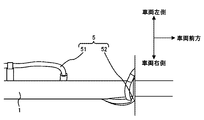
- FIG. 1 shows a state in which pipes are attached to a side frame of a vehicle using the pipe fixing bracket according to the present embodiment.
- FIG. 2 is an enlarged view of the area A in FIG.
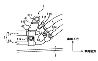
- FIG. 3 is an enlarged view of the area A in FIG. 1 as viewed from the inside of the vehicle.
- FIG. 4 is an enlarged view of the vicinity of the pipe fixing bracket shown in FIG.
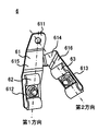
- FIG. 5 shows the structure of the pipe fixing bracket.
- FIG. 6 shows a state in which a pipe is attached to a side frame of a vehicle using a conventional pipe fixing bracket.
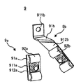
- FIG. 7 shows a structure of a conventional pipe fixing bracket.
- FIG. 1 is a diagram showing a state in which a pipe 5 is attached to a side frame 1 of a vehicle using a pipe fixing bracket 6 according to this embodiment.
- FIG. 1 is a diagram showing a state of the vehicle viewed from above.
- FIG. 2 is an enlarged view of the area A in FIG.
- FIG. 2 is a diagram showing a state of the vehicle viewed from above.
- FIG. 3 is an enlarged view of the area A in FIG. 1 as viewed from the inside of the vehicle.
- the vehicle has a side frame 1, an engine 2, a fuel tank 3, a fuel filter 4, a pipe 5, and a pipe fixing bracket 6.
- the side frame 1 is a member extending in the front-rear direction of the vehicle.
- the side frame 1 has, for example, a U-shaped cross section. Two side frames 1 are provided in parallel.
- the engine 2 generates power for driving the vehicle.
- the engine 2 is, for example, a gasoline engine or a diesel engine.
- the engine 2 supplies fuel (for example, gasoline or light oil) and air and burns it to generate power and generate exhaust gas.
- the engine 2 is provided between the two side frames 1 below the cab of the vehicle.
- the cab is a box-shaped portion with a driver's seat, and is provided in front of the vehicle.
- the fuel tank 3 stores the fuel supplied to the engine 2.
- the fuel is, for example, gasoline or light oil.
- the fuel tank 3 is fixed to the side frame 1 behind the engine 2. Specifically, the fuel tank 3 is fixed to the left side frame 1 of the two side frames 1 in the front direction of the vehicle. The fuel tank 3 is located outside the left side frame 1 in the vehicle width direction of the vehicle.
- the fuel filter 4 is a device for cleaning the fuel that has flowed out of the fuel tank 3 before flowing into the engine 2.
- the fuel filter 4 is provided between the fuel tank 3 and the engine 2.
- the pipe 5 is a pipe for flowing fuel from the fuel tank 3 to the engine 2.
- the pipe 5 has a fuel supply pipe 51 and a fuel recirculation pipe 52.
- the fuel supply pipe 51 is a pipe for flowing fuel from the fuel tank 3 to the engine 2.
- the fuel recirculation pipe 52 is a pipe for flowing fuel from the engine 2 to the fuel tank 3.
- the pipe fixing bracket 6 is a bracket for fixing the pipe 5 to the side frame 1. Specifically, the pipe fixing bracket 6 fixes the fuel supply pipe 51 and the fuel return pipe 52 to the inner surface of the side frame 1.
- FIG. 4 is an enlarged view of the vicinity of the pipe fixing bracket 6 shown in FIG.
- FIG. 5 is a view showing the structure of the pipe fixing bracket 6.
- the pipe fixing bracket 6 has a plate-shaped member 61, a first pipe connecting member 62, and a second pipe connecting member 63.
- the plate-like member 61 connects the pipe fixing bracket 6 to the side frame 1, and connects the pipe fixing bracket 6 to the pipe 5 by the first pipe connecting member 62 and the second pipe connecting member 63.
- the first pipe connecting member 62 and the second pipe connecting member 63 will be described later.
- the plate member 61 has a frame coupling portion 611.
- the frame connecting portion 611 is a portion for connecting the pipe fixing bracket 6 to the side frame 1. Details of the plate member 61 will be described later.
- the first pipe connecting member 62 is a member for connecting the pipe fixing bracket 6 to the first position of the pipe 5. As shown in FIG. 4, the first pipe connecting member 62 is a member for connecting the pipe fixing bracket 6 to the first position of the fuel supply pipe 51 and the first position of the fuel recirculation pipe 52.
- the 1st piping connection member 62 has a press fitting and a screw component. The first position is a predetermined position in the pipe 5.
- the pipe 5 is fixed by the first connecting portion 612 of the pipe fixing bracket 6 and the holding metal fitting of the first pipe connecting member 62.
- the pipe 5 is fixed in a state of being sandwiched between the first coupling portion 612 and the press fitting at the first position.
- it is desirable that the holding metal fitting is fastened to the first coupling portion 612 with a screw component or the like.
- the first coupling portion 612 and the pressing metal fitting will be described later.
- the second pipe connecting member 63 is a part for connecting the pipe fixing bracket 6 to a second position different from the first position in the pipe 5.
- the pipe fixing bracket 6 has a second position different from the first position in the fuel supply pipe 51 and a second position different from the first position in the fuel return pipe 52. It is a site for binding to position 2.
- a bent region is provided between the first position of the pipe 5 and the first position of the pipe 5 in the longitudinal direction of the pipe 5, so that the second position is in the longitudinal direction of the first position of the pipe 5.
- the positions are different in the longitudinal direction.
- the second pipe connecting member 63 has a holding metal fitting and a screw part.
- the pipe 5 is fixed by the second connecting portion 613 of the pipe fixing bracket 6 and the holding metal fitting of the second pipe connecting member 63.
- the pipe 5 is fixed in the second position while being sandwiched between the second coupling portion 613 and the pressing metal fitting.
- it is desirable that the holding metal fitting is fastened to the second coupling portion 613 with a screw component or the like.
- the second connecting portion 613 and the press fitting will be described later.
- FIG. 6 is a diagram showing a state in which the pipe 5 is attached to the side frame 1 of the vehicle using the conventional pipe fixing bracket 9.
- FIG. 7 is a view showing the structure of a conventional pipe fixing bracket 9.
- a first pipe fixing bracket 9a and a second pipe fixing bracket 9b are provided as brackets for fixing the pipe 5 to the side frame 1.
- the first pipe fixing bracket 9a has a first plate-shaped member 91a and a first pipe connecting member 92a.
- the first plate-shaped member 91a has a frame coupling part 911a and a first coupling part 912a.
- the frame connecting portion 911a is a portion for connecting the first pipe fixing bracket 9a to the side frame 1.
- the first coupling portion 912a is a portion to which a first pipe coupling member 92a described later is coupled.
- the first pipe connecting member 92a is a member for connecting the first pipe fixing bracket 9a to the first position of the pipe 5, similarly to the first pipe connecting member 62.
- the second pipe fixing bracket 9b has a second plate-shaped member 91b and a second pipe connecting member 92b.
- the second plate-shaped member 91b is a member for connecting the second pipe fixing bracket 9b to the side frame 1.
- the second plate-shaped member 91b has a frame coupling part 911b and a second coupling part 912b.
- the frame connecting portion 911b is a portion for connecting the second pipe fixing bracket 9b to the side frame 1.
- the second joint portion 912b is a portion to which a second pipe joint member 92b described later is joined.
- the second pipe connecting member 92b is a member for connecting the second pipe fixing bracket 9b to a second position different from the first position in the pipe 5.
- the conventional pipe fixing bracket 9 has the first pipe fixing bracket 9a and the second pipe fixing bracket 9b, and fixes the pipe 5 to the side frame 1 with the two brackets 9a and 9b. ..
- the conventional pipe fixing bracket 9 when fixing the bent pipe 5 to the side frame 1 with the conventional pipe fixing bracket 9, two brackets 9a and 9b are attached to the pipe 5. It takes time to adjust the mounting position and mount. Further, in the conventional pipe fixing bracket 9, when the pipe 5 is attached to and detached from the vehicle side frame 1 using the conventional pipe fixing bracket 9, the two brackets 9a and 9b are attached to and detached from the side frame 1. The need arises. As a result, workability deteriorates when the pipe 5 is attached to and detached from the side frame 1 of the vehicle by using the conventional pipe fixing bracket 9.
- the pipe fixing bracket 6 has the plate-like member 61 having the frame connecting portion 611, the first pipe connecting member 62, and the second pipe connecting member 63 as described above, and the frame connecting portion 611. And the first direction connecting the first pipe connecting member 62 and the second direction connecting the frame connecting portion 611 and the second pipe connecting member 63 are different.
- the pipe fixing bracket 6 for example, when the bent pipe 5 is fixed to the side frame 1 by the pipe fixing bracket 6, the mounting position of the pipe fixing bracket 6 is adjusted with respect to the pipe 5. It is easy to install. Further, in the pipe fixing bracket 6, one pipe fixing bracket 6 may be attached to and detached from the side frame 1 when the pipe 5 is attached to and detached from the side frame 1 of the vehicle. As a result, in the pipe fixing bracket 6, workability is improved when the pipe 5 is attached to and detached from the vehicle side frame 1 by using the pipe fixing bracket 6.
- the plate-shaped member 61 has a frame coupling part 611, a first coupling part 612, a second coupling part 613, and a connection part 614.
- the frame connecting portion 611 is a portion for connecting the pipe fixing bracket 6 to the side frame 1 as described above.
- the frame coupling portion 611 is a plate-shaped portion having a hole.
- the plate member 61 is attached to the side frame 1 by inserting a bolt into the hole of the frame coupling portion 611 and a hole formed in the side frame 1 and tightening a nut on the inserted bolt.
- the first joint portion 612 is a portion to which the first pipe joint member 62 is joined.
- the first coupling portion 612 is a plate-shaped portion having a hole. For example, a bolt included in the screw component of the first pipe coupling member 62 is inserted into the hole.
- the second coupling portion 613 is a portion to which the second pipe coupling member 63 is coupled.
- the second coupling portion 613 is a plate-shaped portion having a hole, like the first coupling portion 612. For example, the bolt included in the screw component of the second pipe coupling member 63 is inserted into the hole.
- connection part 614 is a part that connects the frame connection part 611, the first connection part 612, and the second connection part 613 in a state where the first connection part 612 and the second connection part 613 are branched from the frame connection part 611. is there.
- the plate-shaped member 61 has a first plate portion 615 and a second plate portion 616, and the second plate portion 616 is branched from the first plate portion 615.
- the first plate portion 615 is an area including the frame coupling portion 611 and the first coupling portion 612.
- the second plate portion 616 is an area including the second coupling portion 613.
- the plate-shaped member 61 has a shape in which the first connecting portion 612 and the second connecting portion 613 are branched from the frame connecting portion 611 via the connecting portion 614 as described above. Therefore, in the pipe fixing bracket 6, for example, the plate-shaped member 61 has a flat plate shape including the frame coupling portion 611, the first coupling portion 612, and the second coupling portion 613, compared to the plate-shaped member 61. Materials can be saved.
- connection portion 614 connects the first coupling portion 612 and the second coupling portion 613 in a state in which the direction in which the first coupling portion 612 extends and the direction in which the second coupling portion 613 extend are different. To do. That is, the direction in which the first plate portion 615 extends is different from the direction in which the second plate portion 616 extends.
- the pipe fixing bracket 6 is configured such that the plate-shaped member 61 has the first connecting portion 612 extending in a direction different from the second connecting portion 613 extending in the first direction. It has a connecting portion 614 that connects the coupling portion 612 and the second coupling portion 613. Therefore, the pipe fixing bracket 6 can fix, for example, the pipe 5 that is bent in the direction orthogonal to the direction in which the first plate portion 615 extends. As a result, the pipe fixing bracket 6 improves the degree of freedom of the pipe 5 that can be fixed to the side frame 1 by the pipe fixing bracket 6.
- the pipe 5 is fixed to the side frame 1 by the pipe fixing bracket 6 in the above embodiment, the present invention is not limited to this.
- the pipe 5 may have a structure in which it is fixed to the frame of the vehicle by a pipe fixing bracket 6, for example.
- the structure in which the fuel supply pipe 51 and the fuel recirculation pipe 52 are provided as the pipe 5 is shown, but the structure is not limited thereto.
- the pipe 5 for example, a pipe that supplies air to the brake of the vehicle may be provided.
- the structure in which two pipes 5 are provided is shown, but the structure is not limited to this.
- the number provided as the pipe 5 is arbitrary.
- the pipe fixing bracket 6 is a pipe fixing bracket 6 for fixing the pipe 5 of the vehicle to the side frame 1 of the vehicle, and is for connecting the pipe fixing bracket 6 to the side frame 1. It has a plate-shaped member 61 having a frame coupling portion 611.
- the pipe fixing bracket 6 is different from the first pipe connecting member 62 for connecting the pipe fixing bracket 6 to the first position of the pipe 5 and the pipe fixing bracket 6 from the first position of the pipe 5.
- a second pipe coupling member 63 for coupling to a second position.
- the pipe fixing bracket 6 is different in the first direction connecting the frame connecting portion 611 and the first pipe connecting member 62 and the second direction connecting the frame connecting portion 611 and the second pipe connecting member 63.
- the pipe fixing bracket 6 has the plate-like member 61 having the frame connecting portion 611, the first pipe connecting member 62, and the second pipe connecting member 63, and is connected to the frame connecting portion 611.
- the first direction connecting the first pipe connecting member 62 and the second direction connecting the frame connecting portion 611 and the second pipe connecting member 63 are different.
- the pipe fixing bracket 6 for example, when the bent pipe 5 is fixed to the side frame 1 by the pipe fixing bracket 6, the mounting position of the pipe fixing bracket 6 is adjusted with respect to the pipe 5. Is easy to install. Further, in the pipe fixing bracket 6, one pipe fixing bracket 6 may be attached to and detached from the side frame 1 when the pipe 5 is attached to and detached from the side frame 1 of the vehicle. As a result, when the pipe fixing bracket 6 is attached to or detached from the vehicle side frame 1 by using the pipe fixing bracket 6, the workability is less likely to deteriorate.
- the present disclosure has been described using the embodiments, the technical scope of the present disclosure is not limited to the scope described in the above embodiments, and various modifications and changes are possible within the scope of the gist thereof. is there.
- the specific embodiment of device distribution/integration is not limited to the above embodiment, and all or part of the device may be functionally or physically distributed/integrated in arbitrary units.
- You can Further, a new embodiment generated by an arbitrary combination of a plurality of embodiments is also included in the embodiments of the present disclosure. The effect of the new embodiment produced by the combination also has the effect of the original embodiment.
Landscapes
- Engineering & Computer Science (AREA)
- Chemical & Material Sciences (AREA)
- Combustion & Propulsion (AREA)
- Mechanical Engineering (AREA)
- General Engineering & Computer Science (AREA)
- Cooling, Air Intake And Gas Exhaust, And Fuel Tank Arrangements In Propulsion Units (AREA)
- Body Structure For Vehicles (AREA)
Abstract
配管固定用ブラケット6は、車両の配管5を車両のフレームに固定するための配管固定用ブラケット6であって、配管固定用ブラケット6をフレームに結合するためのフレーム結合部611を有する板状部材61と、配管固定用ブラケット6を配管5の第1の位置に結合するための第1配管結合部材62と、配管固定用ブラケット6を配管5における第1の位置と異なる第2の位置に結合するための第2配管結合部材63と、を有し、フレーム結合部611と第1配管結合部材62とを結ぶ第1方向とフレーム結合部611と第2配管結合部材63とを結ぶ第2方向とが異なる。
Description
本開示は、配管固定用ブラケット及び車両に関する。
従来、車両には配管固定用ブラケットが設けられている。特許文献1には、車両のパワーステアリング用クーラ配管の両端部が、2つのクーラ配管取り付け手段によって、車体フレームにそれぞれ取付け固定されている構造が開示されている。
車両のサイドフレームに複数の配管固定用ブラケットを用いて配管が取付けられている場合がある。この場合、配管固定用ブラケット及び配管の着脱時の作業性が低下してしまうという問題が生じていた。
そこで、本開示はこれらの点に鑑みてなされたものであり、車両のフレームに配管固定用ブラケットを用いて配管を着脱する際に、作業性が低下しづらい配管固定用ブラケット及び車両を提供することを目的とする。
本開示の第1の態様においては、車両の配管を前記車両のフレームに固定するための配管固定用ブラケットであって、前記配管固定用ブラケットを前記フレームに結合するためのフレーム結合部を有する板状部材と、前記配管固定用ブラケットを前記配管の第1の位置に結合するための第1配管結合部材と、前記配管固定用ブラケットを前記配管における前記第1の位置と異なる第2の位置に結合するための第2配管結合部材と、を有し、前記フレーム結合部と前記第1配管結合部材とを結ぶ第1方向と前記フレーム結合部と前記第2配管結合部材とを結ぶ第2方向とが異なることを特徴とする配管固定用ブラケットを提供する。
また、前記板状部材は、前記第1配管結合部材が結合される第1結合部と、前記第2配管結合部材が結合される第2結合部と、前記フレーム結合部から前記第1結合部と前記第2結合部とが分岐した状態で、前記フレーム結合部、前記第1結合部、及び前記第2結合部を接続する接続部と、を有していてもよい。
また、前記接続部は、前記第1結合部が延在している方向と前記第2結合部が延在している方向とが異なる状態で、前記第1結合部と前記第2結合部とを接続していてもよい。
本開示の第2の態様においては、上記のいずれかに記載の配管固定用ブラケットと、前記車両のエンジンに供給する燃料を流す燃料供給配管と、を有し、前記第1配管結合部材は、前記配管固定用ブラケットを前記燃料供給配管の第1の位置に結合し、前記第2配管結合部材は、前記配管固定用ブラケットを前記燃料供給配管の第2の位置に結合することを特徴とする車両を提供する。
本開示によれば、車両のフレームに配管固定用ブラケットを用いて配管を着脱する際に、作業性が低下しづらくなるという効果を奏する。
<本実施形態>[配管固定用ブラケット6の周辺構成]
図1は、本実施形態に係る配管固定用ブラケット6を用いて配管5が車両のサイドフレーム1に取付けられている状態を示す図である。なお、図1は、車両を上方から見た状態を示す図である。図2は、図1の領域Aの部分の拡大図である。なお、図2は、車両を上方から見た状態を示す図である。図3は、図1の領域Aの部分を車両の内側から見た拡大図である。
図1は、本実施形態に係る配管固定用ブラケット6を用いて配管5が車両のサイドフレーム1に取付けられている状態を示す図である。なお、図1は、車両を上方から見た状態を示す図である。図2は、図1の領域Aの部分の拡大図である。なお、図2は、車両を上方から見た状態を示す図である。図3は、図1の領域Aの部分を車両の内側から見た拡大図である。
車両は、サイドフレーム1、エンジン2、燃料タンク3、燃料フィルタ4、配管5、及び配管固定用ブラケット6を有する。サイドフレーム1は、車両の前後方向において延伸している部材である。サイドフレーム1は、例えば断面がコ字形状である。2本のサイドフレーム1が平行に設けられている。
エンジン2は、車両を駆動するための動力を発生する。エンジン2は、例えばガソリンエンジン又はディーゼルエンジンである。エンジン2は、燃料(例えば、ガソリン又は軽油)及び空気を供給して燃焼させることで動力を発生すると共に排気ガスを生じる。エンジン2は、車両のキャブの下方において、2本のサイドフレーム1の間に設けられている。キャブは、運転席のある箱形状の部分であり、車両の前方に設けられている。
燃料タンク3は、エンジン2に供給する燃料を貯留する。燃料は、例えばガソリン又は軽油である。燃料タンク3は、エンジン2より後方においてサイドフレーム1に固定されている。具体的には、燃料タンク3は、2本のサイドフレーム1のうち、車両の前方方向に向かって左側のサイドフレーム1に固定されている。燃料タンク3は、当該左側のサイドフレーム1の車両の車幅方向における外側に位置する。
燃料フィルタ4は、燃料タンク3から流出させた燃料をエンジン2に流入させる前に、当該燃料を清浄にするための機器である。燃料フィルタ4は、燃料タンク3とエンジン2との間に設けられている。
配管5は、燃料タンク3からエンジン2に燃料を流す配管である。配管5は、燃料供給配管51、及び燃料還流配管52を有する。燃料供給配管51は、燃料タンク3からエンジン2に燃料を流す配管である。燃料還流配管52は、エンジン2から燃料タンク3に燃料を流す配管である。
図1~図3に示すように、燃料供給配管51は、燃料タンク3からエンジン2に向かって、サイドフレーム1に形成されている穴を通して、サイドフレーム1の外側から内側に向かって貫通した後に、サイドフレーム1の内側において、上方に向かって曲げられている。燃料還流配管52は、エンジン2から燃料タンク3に向かって、サイドフレーム1の内側において後方に向かって曲げられており、サイドフレーム1の内側において後方に向かって延伸した後に、サイドフレーム1の内側から外側に向かって貫通している。
配管固定用ブラケット6は、配管5をサイドフレーム1に固定するためのブラケットである。具体的には、配管固定用ブラケット6は、燃料供給配管51及び燃料還流配管52をサイドフレーム1の内側面に固定している。
[配管固定用ブラケット6の構造]
図4は、図3で示す配管固定用ブラケット6付近の拡大図である。図5は、配管固定用ブラケット6の構造を示す図である。
図4は、図3で示す配管固定用ブラケット6付近の拡大図である。図5は、配管固定用ブラケット6の構造を示す図である。
配管固定用ブラケット6は、板状部材61、第1配管結合部材62、及び第2配管結合部材63を有する。板状部材61は、配管固定用ブラケット6をサイドフレーム1に結合し、かつ配管5に配管固定用ブラケット6を第1配管結合部材62、及び第2配管結合部材63によって結合する。なお、第1配管結合部材62及び第2配管結合部材63については後述する。板状部材61は、フレーム結合部611を有する。フレーム結合部611は、配管固定用ブラケット6をサイドフレーム1に結合するための部位である。板状部材61の詳細は後述する。
第1配管結合部材62は、配管固定用ブラケット6を配管5の第1の位置に結合するための部材である。図4に示すように、第1配管結合部材62は、配管固定用ブラケット6を燃料供給配管51の第1の位置、及び燃料還流配管52の第1の位置に結合するための部材である。第1配管結合部材62は、押さえ金具とねじ部品を有する。第1の位置は、配管5における所定の位置である。
配管5は、配管固定用ブラケット6の第1結合部612と第1配管結合部材62の押さえ金具とで固定されている。例えば、配管5は、第1の位置において、第1結合部612と押さえ金具との間に挟まれた状態で固定されている。この場合、押さえ金具は、ねじ部品等で第1結合部612に締め付けられていることが望ましい。なお、第1結合部612及び押さえ金具については、後述する。
第2配管結合部材63は、配管固定用ブラケット6を配管5における第1の位置と異なる第2の位置に結合するための部位である。図4に示すように、第2配管結合部材63は、配管固定用ブラケット6を燃料供給配管51における第1の位置と異なる第2の位置、及び燃料還流配管52における第1の位置と異なる第2の位置に結合するための部位である。第2の位置は、配管5の長手方向において、配管5の第1の位置との間に、曲げられている領域が設けられていることで、配管5の第1の位置における長手方向と、長手方向の向きが異なる位置である。
第2配管結合部材63は、第1配管結合部材62と同様に、押さえ金具とねじ部品を有する。配管5は、配管固定用ブラケット6の第2結合部613と第2配管結合部材63の押さえ金具とで固定されている。例えば、配管5は、第2の位置において、第2結合部613と押さえ金具との間に挟まれた状態で固定されている。この場合、押さえ金具は、ねじ部品等で第2結合部613に締め付けられていることが望ましい。なお、第2結合部613及び押さえ金具については、後述する。
図5に示すように、配管固定用ブラケット6においては、フレーム結合部611と第1配管結合部材62とを結ぶ第1方向とフレーム結合部611と第2配管結合部材63とを結ぶ第2方向とは異なる。
図6は、従来の配管固定用ブラケット9を用いて配管5が車両のサイドフレーム1に取付けられている状態を示す図である。図7は、従来の配管固定用ブラケット9の構造を示す図である。
従来の配管固定用ブラケット9において、配管5をサイドフレーム1に固定するためのブラケットとして、第1配管固定用ブラケット9a、及び第2配管固定用ブラケット9bが設けられている。
従来の配管固定用ブラケット9において、配管5をサイドフレーム1に固定するためのブラケットとして、第1配管固定用ブラケット9a、及び第2配管固定用ブラケット9bが設けられている。
第1配管固定用ブラケット9aは、第1板状部材91a、及び第1配管結合部材92aを有する。第1板状部材91aは、フレーム結合部911a、及び第1結合部912aを有する。フレーム結合部911aは、第1配管固定用ブラケット9aをサイドフレーム1に結合するための部位である。第1結合部912aは、後述する第1配管結合部材92aが結合される部位である。第1配管結合部材92aは、第1配管結合部材62と同様に、第1配管固定用ブラケット9aを配管5の第1の位置に結合するための部材である。
第2配管固定用ブラケット9bは、第2板状部材91b、及び第2配管結合部材92bを有する。第2板状部材91bは、第2配管固定用ブラケット9bをサイドフレーム1に結合するための部材である。第2板状部材91bは、フレーム結合部911b、及び第2結合部912bを有する。フレーム結合部911bは、第2配管固定用ブラケット9bをサイドフレーム1に結合するための部位である。第2結合部912bは、後述する第2配管結合部材92bが結合される部位である。
第2配管結合部材92bは、第2配管結合部材63と同様に、第2配管固定用ブラケット9bを配管5における第1の位置と異なる第2の位置に結合するための部材である。
このように、従来の配管固定用ブラケット9は、第1配管固定用ブラケット9a、及び第2配管固定用ブラケット9bを有し、配管5を2つのブラケット9a、及び9bでサイドフレーム1に固定する。
よって、従来の配管固定用ブラケット9においては、例えば、曲げられている配管5をサイドフレーム1に従来の配管固定用ブラケット9で固定する場合、配管5に対して2つのブラケット9a、及び9bの取付位置を調整して取付けるのに手間がかかってしまう。また、従来の配管固定用ブラケット9においては、車両のサイドフレーム1に従来の配管固定用ブラケット9を用いて配管5を着脱する際に、2つのブラケット9a、及び9bをサイドフレーム1に着脱する必要が生じる。この結果、車両のサイドフレーム1に従来の配管固定用ブラケット9を用いて配管5を着脱する際には、作業性が低下してしまう。
これに対して、配管固定用ブラケット6は、上述したように、フレーム結合部611を有する板状部材61、第1配管結合部材62、及び第2配管結合部材63を有し、フレーム結合部611と第1配管結合部材62とを結ぶ第1方向とフレーム結合部611と第2配管結合部材63とを結ぶ第2方向とは異なっている。
よって、配管固定用ブラケット6においては、例えば、曲げられている配管5をサイドフレーム1に配管固定用ブラケット6で固定する場合に、配管5に対して配管固定用ブラケット6の取付位置を調整して取付けることが容易である。また、配管固定用ブラケット6においては、車両のサイドフレーム1に配管固定用ブラケット6を用いて配管5を着脱する際に、1つの配管固定用ブラケット6をサイドフレーム1に着脱すればよい。この結果、配管固定用ブラケット6においては、車両のサイドフレーム1に配管固定用ブラケット6を用いて配管5を着脱する際に、作業性が向上する。
[板状部材61の詳細構造]
板状部材61は、フレーム結合部611、第1結合部612、第2結合部613、及び接続部614を有する。フレーム結合部611は、上述したように配管固定用ブラケット6をサイドフレーム1に結合するための部位である。具体的には、フレーム結合部611は、穴を有する板状の部位である。板状部材61は、フレーム結合部611の当該穴とサイドフレーム1に形成されている穴とにボルトを挿入して、挿入したボルトにナットを締め付けることで、サイドフレーム1に取付けられている。
板状部材61は、フレーム結合部611、第1結合部612、第2結合部613、及び接続部614を有する。フレーム結合部611は、上述したように配管固定用ブラケット6をサイドフレーム1に結合するための部位である。具体的には、フレーム結合部611は、穴を有する板状の部位である。板状部材61は、フレーム結合部611の当該穴とサイドフレーム1に形成されている穴とにボルトを挿入して、挿入したボルトにナットを締め付けることで、サイドフレーム1に取付けられている。
第1結合部612は、第1配管結合部材62が結合される部位である。第1結合部612は、穴を有する板状の部位である。当該穴には、例えば、第1配管結合部材62のねじ部品に含まれるボルトが挿入される。第2結合部613は、第2配管結合部材63が結合される部位である。第2結合部613は、第1結合部612と同様に、穴を有する板状の部位である。当該穴には、例えば、第2配管結合部材63のねじ部品に含まれるボルトが挿入される。
接続部614は、フレーム結合部611から第1結合部612と第2結合部613とが分岐した状態で、フレーム結合部611、第1結合部612、及び第2結合部613を接続する部位である。
すなわち、板状部材61は、第1板部615、及び第2板部616を有し、第2板部616は、第1板部615から分岐している。第1板部615は、フレーム結合部611と第1結合部612とを含む領域である。第2板部616は、第2結合部613を含む領域である。
配管固定用ブラケット6においては、このように、板状部材61が、フレーム結合部611から接続部614を介して、第1結合部612、及び第2結合部613が分岐した形状である。よって、配管固定用ブラケット6においては、例えば板状部材61が、フレーム結合部611、第1結合部612、及び第2結合部613を含む平板形状である場合に比べて、板状部材61の材料が節減できる。
接続部614は、第1結合部612が延在している方向と第2結合部613が延在している方向とが異なる状態で、第1結合部612と第2結合部613とを接続する。すなわち、第1板部615が延在している方向と第2板部616が延在している方向とは異なっている。
配管固定用ブラケット6は、このように、板状部材61が、第1結合部612が延在している方向と第2結合部613が延在している方向とが異なる状態で、第1結合部612と第2結合部613とを接続する接続部614を有している。よって、配管固定用ブラケット6は、例えば、第1板部615が延在している方向と直交する方向において曲げられている配管5を固定することが可能になる。この結果、配管固定用ブラケット6は、配管固定用ブラケット6でサイドフレーム1に固定可能な配管5の自由度が向上する。
[変形例]
上記実施形態においては、配管5は配管固定用ブラケット6でサイドフレーム1に固定されている構造を示したが、これに限定されない。配管5は、例えば配管固定用ブラケット6で車両のフレームに固定されている構造であってもよい。
上記実施形態においては、配管5は配管固定用ブラケット6でサイドフレーム1に固定されている構造を示したが、これに限定されない。配管5は、例えば配管固定用ブラケット6で車両のフレームに固定されている構造であってもよい。
また、上記実施形態においては、配管5として、燃料供給配管51、及び燃料還流配管52が設けられている構造を示したが、これに限定されない。配管5として、例えば車両のブレーキに空気を供給する配管が設けられていてもよい。
また、上記実施形態においては、配管5として2本設けられている構造を示したが、これに限定されない。配管5として設けられている数は任意である。
[本実施形態に係る配管固定用ブラケット6による効果]
本実施形態に係る配管固定用ブラケット6は、車両の配管5を車両のサイドフレーム1に固定するための配管固定用ブラケット6であって、配管固定用ブラケット6をサイドフレーム1に結合するためのフレーム結合部611を有する板状部材61を有する。また、配管固定用ブラケット6は、配管固定用ブラケット6を配管5の第1の位置に結合するための第1配管結合部材62と、配管固定用ブラケット6を配管5における第1の位置と異なる第2の位置に結合するための第2配管結合部材63と、を有する。そして、配管固定用ブラケット6は、フレーム結合部611と第1配管結合部材62とを結ぶ第1方向とフレーム結合部611と第2配管結合部材63とを結ぶ第2方向とが異なる。
本実施形態に係る配管固定用ブラケット6は、車両の配管5を車両のサイドフレーム1に固定するための配管固定用ブラケット6であって、配管固定用ブラケット6をサイドフレーム1に結合するためのフレーム結合部611を有する板状部材61を有する。また、配管固定用ブラケット6は、配管固定用ブラケット6を配管5の第1の位置に結合するための第1配管結合部材62と、配管固定用ブラケット6を配管5における第1の位置と異なる第2の位置に結合するための第2配管結合部材63と、を有する。そして、配管固定用ブラケット6は、フレーム結合部611と第1配管結合部材62とを結ぶ第1方向とフレーム結合部611と第2配管結合部材63とを結ぶ第2方向とが異なる。
本実施形態に係る配管固定用ブラケット6は、このように、フレーム結合部611を有する板状部材61、第1配管結合部材62、及び第2配管結合部材63を有し、フレーム結合部611と第1配管結合部材62とを結ぶ第1方向とフレーム結合部611と第2配管結合部材63とを結ぶ第2方向とが異なる。
よって、配管固定用ブラケット6においては、例えば、曲げられている配管5をサイドフレーム1に配管固定用ブラケット6で固定する場合に、配管5に対して配管固定用ブラケット6の取付位置を調整して取付けるのに手間がかかりづらい。また、配管固定用ブラケット6においては、車両のサイドフレーム1に配管固定用ブラケット6を用いて配管5を着脱する際に、1つの配管固定用ブラケット6をサイドフレーム1に着脱すればよい。この結果、配管固定用ブラケット6においては、車両のサイドフレーム1に配管固定用ブラケット6を用いて配管5を着脱する際に、作業性が低下しづらくなる。
以上、本開示を実施の形態を用いて説明したが、本開示の技術的範囲は上記実施の形態に記載の範囲には限定されず、その要旨の範囲内で種々の変形及び変更が可能である。例えば、装置の分散・統合の具体的な実施の形態は、以上の実施の形態に限られず、その全部又は一部について、任意の単位で機能的又は物理的に分散・統合して構成することができる。また、複数の実施の形態の任意の組み合わせによって生じる新たな実施の形態も、本開示の実施の形態に含まれる。組み合わせによって生じる新たな実施の形態の効果は、もとの実施の形態の効果を合わせ持つ。
本出願は、2019年2月12日付で出願された日本国特許出願(特願2019-22919)に基づくものであり、その内容はここに参照として取り込まれる。
本開示によれば、車両のフレームに配管固定用ブラケットを用いて配管を着脱する際に、作業性が低下しづらくなる点において有用である。
1・・・サイドフレーム
2・・・エンジン
3・・・燃料タンク
4・・・燃料フィルタ
5・・・配管
51・・・燃料供給配管
52・・・燃料還流配管
6・・・配管固定用ブラケット
61・・・板状部材
611・・・フレーム結合部
612・・・第1結合部
613・・・第2結合部
614・・・接続部
615・・・第1板部
616・・・第2板部
62・・・第1配管結合部材
63・・・第2配管結合部材
9・・・従来の配管固定用ブラケット
9a・・・第1配管固定用ブラケット
91a・・・第1板状部材
911a・・・フレーム結合部
912a・・・第1結合部
92a・・・第1配管結合部材
9b・・・第2配管固定用ブラケット
91b・・・第2板状部材
911b・・・フレーム結合部
912b・・・第2結合部
92b・・・第2配管結合部材
2・・・エンジン
3・・・燃料タンク
4・・・燃料フィルタ
5・・・配管
51・・・燃料供給配管
52・・・燃料還流配管
6・・・配管固定用ブラケット
61・・・板状部材
611・・・フレーム結合部
612・・・第1結合部
613・・・第2結合部
614・・・接続部
615・・・第1板部
616・・・第2板部
62・・・第1配管結合部材
63・・・第2配管結合部材
9・・・従来の配管固定用ブラケット
9a・・・第1配管固定用ブラケット
91a・・・第1板状部材
911a・・・フレーム結合部
912a・・・第1結合部
92a・・・第1配管結合部材
9b・・・第2配管固定用ブラケット
91b・・・第2板状部材
911b・・・フレーム結合部
912b・・・第2結合部
92b・・・第2配管結合部材
Claims (4)
- 車両の配管を前記車両のフレームに固定するための配管固定用ブラケットであって、
前記配管固定用ブラケットを前記フレームに結合するためのフレーム結合部を有する板状部材と、
前記配管固定用ブラケットを前記配管の第1の位置に結合するための第1配管結合部材と、
前記配管固定用ブラケットを前記配管における前記第1の位置と異なる第2の位置に結合するための第2配管結合部材と、
を有し、
前記フレーム結合部と前記第1配管結合部材とを結ぶ第1方向と前記フレーム結合部と前記第2配管結合部材とを結ぶ第2方向とが異なることを特徴とする配管固定用ブラケット。 - 前記板状部材は、
前記第1配管結合部材が結合される第1結合部と、
前記第2配管結合部材が結合される第2結合部と、
前記フレーム結合部から前記第1結合部と前記第2結合部とが分岐した状態で、前記フレーム結合部、前記第1結合部、及び前記第2結合部を接続する接続部と、
を有することを特徴とする、
請求項1に記載の配管固定用ブラケット。 - 前記接続部は、前記第1結合部が延在している方向と前記第2結合部が延在している方向とが異なる状態で、前記第1結合部と前記第2結合部とを接続することを特徴とする、
請求項2に記載の配管固定用ブラケット。 - 請求項1から3のいずれか一項に記載の配管固定用ブラケットと、
前記車両のエンジンに供給する燃料を流す燃料供給配管と、
を有し、
前記第1配管結合部材は、前記配管固定用ブラケットを前記燃料供給配管の第1の位置に結合し、
前記第2配管結合部材は、前記配管固定用ブラケットを前記燃料供給配管の第2の位置に結合することを特徴とする車両。
Priority Applications (1)
| Application Number | Priority Date | Filing Date | Title |
|---|---|---|---|
| CN202080013645.2A CN113423941A (zh) | 2019-02-12 | 2020-02-06 | 配管固定用托架以及车辆 |
Applications Claiming Priority (2)
| Application Number | Priority Date | Filing Date | Title |
|---|---|---|---|
| JP2019-022919 | 2019-02-12 | ||
| JP2019022919A JP2020133397A (ja) | 2019-02-12 | 2019-02-12 | 配管固定用ブラケット及び車両 |
Publications (1)
| Publication Number | Publication Date |
|---|---|
| WO2020166467A1 true WO2020166467A1 (ja) | 2020-08-20 |
Family
ID=72044734
Family Applications (1)
| Application Number | Title | Priority Date | Filing Date |
|---|---|---|---|
| PCT/JP2020/004469 Ceased WO2020166467A1 (ja) | 2019-02-12 | 2020-02-06 | 配管固定用ブラケット及び車両 |
Country Status (3)
| Country | Link |
|---|---|
| JP (1) | JP2020133397A (ja) |
| CN (1) | CN113423941A (ja) |
| WO (1) | WO2020166467A1 (ja) |
Citations (2)
| Publication number | Priority date | Publication date | Assignee | Title |
|---|---|---|---|---|
| US20090026673A1 (en) * | 2007-07-23 | 2009-01-29 | Clark Sylvester S | Vibration-dampening clip assembly |
| CN203902265U (zh) * | 2014-06-04 | 2014-10-29 | 安徽江淮汽车股份有限公司 | 一种应用在轻型卡车上的燃油管支架 |
Family Cites Families (4)
| Publication number | Priority date | Publication date | Assignee | Title |
|---|---|---|---|---|
| JP2005186724A (ja) * | 2003-12-25 | 2005-07-14 | Suzuki Motor Corp | 車両の燃料配管構造 |
| JP4479740B2 (ja) * | 2007-03-23 | 2010-06-09 | 日産自動車株式会社 | 車体前部構造及び車体前部配管固定用ブラケット |
| JP5675413B2 (ja) * | 2011-02-14 | 2015-02-25 | 本田技研工業株式会社 | 自動二輪車の車体フレーム |
| JP2015074353A (ja) * | 2013-10-09 | 2015-04-20 | ヤマハ発動機株式会社 | 鞍乗型車両 |
-
2019
- 2019-02-12 JP JP2019022919A patent/JP2020133397A/ja active Pending
-
2020
- 2020-02-06 WO PCT/JP2020/004469 patent/WO2020166467A1/ja not_active Ceased
- 2020-02-06 CN CN202080013645.2A patent/CN113423941A/zh not_active Withdrawn
Patent Citations (2)
| Publication number | Priority date | Publication date | Assignee | Title |
|---|---|---|---|---|
| US20090026673A1 (en) * | 2007-07-23 | 2009-01-29 | Clark Sylvester S | Vibration-dampening clip assembly |
| CN203902265U (zh) * | 2014-06-04 | 2014-10-29 | 安徽江淮汽车股份有限公司 | 一种应用在轻型卡车上的燃油管支架 |
Also Published As
| Publication number | Publication date |
|---|---|
| JP2020133397A (ja) | 2020-08-31 |
| CN113423941A (zh) | 2021-09-21 |
Similar Documents
| Publication | Publication Date | Title |
|---|---|---|
| CA2673402C (en) | Intake structure of vehicle | |
| US6758300B2 (en) | Exhaust isolator system | |
| CN103895720B (zh) | 多用途车辆 | |
| US7665560B2 (en) | Drivetrain for hybrid electric vehicle | |
| US10829178B2 (en) | Vehicle body frame of straddle-type vehicle | |
| JP5898402B2 (ja) | 自動二輪車の車体フレーム | |
| JP5620810B2 (ja) | 自動二輪車の車体フレーム | |
| MX2014007138A (es) | Ensamblado de la suspension de la direccion para vehiculo. | |
| US8833502B2 (en) | Muffler assembly | |
| JP6107638B2 (ja) | エンジンの排気系部品取付構造、及びエンジンの排気系部品取付方法 | |
| JP2004182154A (ja) | 車体前部構造 | |
| JP7009268B2 (ja) | 作業車 | |
| US12054196B2 (en) | Systems for a fastening device of an exhaust-gas aftertreatment system | |
| TWI238220B (en) | Motorcycle | |
| CN104554543A (zh) | 跨乘式车辆 | |
| JP2018123766A (ja) | 燃料配管の支持構造 | |
| JPH0771245A (ja) | エンジンの排気装置 | |
| JP2020133397A (ja) | 配管固定用ブラケット及び車両 | |
| US7866709B2 (en) | Crosstalk device for an exhaust system | |
| EP2949526B1 (en) | Saddle-straddling type motor vehicle | |
| JP3840732B2 (ja) | エンジンの燃料配管構造 | |
| JP2010137736A (ja) | サスペンションメンバ構造 | |
| US7513491B2 (en) | Engine mount system | |
| DE102015116207A1 (de) | Abgassystem eines Kraftfahrzeugs mit einem Sattel | |
| CN103661721B (zh) | 跨乘式车辆的框架结构 |
Legal Events
| Date | Code | Title | Description |
|---|---|---|---|
| 121 | Ep: the epo has been informed by wipo that ep was designated in this application |
Ref document number: 20755555 Country of ref document: EP Kind code of ref document: A1 |
|
| NENP | Non-entry into the national phase |
Ref country code: DE |
|
| 122 | Ep: pct application non-entry in european phase |
Ref document number: 20755555 Country of ref document: EP Kind code of ref document: A1 |