WO2020166331A1 - 光周波数反射計測装置およびその計測方法 - Google Patents
光周波数反射計測装置およびその計測方法 Download PDFInfo
- Publication number
- WO2020166331A1 WO2020166331A1 PCT/JP2020/003108 JP2020003108W WO2020166331A1 WO 2020166331 A1 WO2020166331 A1 WO 2020166331A1 JP 2020003108 W JP2020003108 W JP 2020003108W WO 2020166331 A1 WO2020166331 A1 WO 2020166331A1
- Authority
- WO
- WIPO (PCT)
- Prior art keywords
- light
- optical fiber
- delay
- frequency
- optical
- Prior art date
- Legal status (The legal status is an assumption and is not a legal conclusion. Google has not performed a legal analysis and makes no representation as to the accuracy of the status listed.)
- Ceased
Links
Images


Classifications
-
- H—ELECTRICITY
- H04—ELECTRIC COMMUNICATION TECHNIQUE
- H04B—TRANSMISSION
- H04B10/00—Transmission systems employing electromagnetic waves other than radio-waves, e.g. infrared, visible or ultraviolet light, or employing corpuscular radiation, e.g. quantum communication
- H04B10/07—Arrangements for monitoring or testing transmission systems; Arrangements for fault measurement of transmission systems
- H04B10/071—Arrangements for monitoring or testing transmission systems; Arrangements for fault measurement of transmission systems using a reflected signal, e.g. using optical time domain reflectometers [OTDR]
-
- G—PHYSICS
- G01—MEASURING; TESTING
- G01B—MEASURING LENGTH, THICKNESS OR SIMILAR LINEAR DIMENSIONS; MEASURING ANGLES; MEASURING AREAS; MEASURING IRREGULARITIES OF SURFACES OR CONTOURS
- G01B11/00—Measuring arrangements characterised by the use of optical techniques
-
- G—PHYSICS
- G01—MEASURING; TESTING
- G01D—MEASURING NOT SPECIALLY ADAPTED FOR A SPECIFIC VARIABLE; ARRANGEMENTS FOR MEASURING TWO OR MORE VARIABLES NOT COVERED IN A SINGLE OTHER SUBCLASS; TARIFF METERING APPARATUS; MEASURING OR TESTING NOT OTHERWISE PROVIDED FOR
- G01D5/00—Mechanical means for transferring the output of a sensing member; Means for converting the output of a sensing member to another variable where the form or nature of the sensing member does not constrain the means for converting; Transducers not specially adapted for a specific variable
- G01D5/26—Mechanical means for transferring the output of a sensing member; Means for converting the output of a sensing member to another variable where the form or nature of the sensing member does not constrain the means for converting; Transducers not specially adapted for a specific variable characterised by optical transfer means, i.e. using infrared, visible, or ultraviolet light
- G01D5/32—Mechanical means for transferring the output of a sensing member; Means for converting the output of a sensing member to another variable where the form or nature of the sensing member does not constrain the means for converting; Transducers not specially adapted for a specific variable characterised by optical transfer means, i.e. using infrared, visible, or ultraviolet light with attenuation or whole or partial obturation of beams of light
- G01D5/34—Mechanical means for transferring the output of a sensing member; Means for converting the output of a sensing member to another variable where the form or nature of the sensing member does not constrain the means for converting; Transducers not specially adapted for a specific variable characterised by optical transfer means, i.e. using infrared, visible, or ultraviolet light with attenuation or whole or partial obturation of beams of light the beams of light being detected by photocells
- G01D5/353—Mechanical means for transferring the output of a sensing member; Means for converting the output of a sensing member to another variable where the form or nature of the sensing member does not constrain the means for converting; Transducers not specially adapted for a specific variable characterised by optical transfer means, i.e. using infrared, visible, or ultraviolet light with attenuation or whole or partial obturation of beams of light the beams of light being detected by photocells influencing the transmission properties of an optical fibre
-
- H—ELECTRICITY
- H04—ELECTRIC COMMUNICATION TECHNIQUE
- H04B—TRANSMISSION
- H04B10/00—Transmission systems employing electromagnetic waves other than radio-waves, e.g. infrared, visible or ultraviolet light, or employing corpuscular radiation, e.g. quantum communication
- H04B10/25—Arrangements specific to fibre transmission
- H04B10/2507—Arrangements specific to fibre transmission for the reduction or elimination of distortion or dispersion
-
- G—PHYSICS
- G01—MEASURING; TESTING
- G01M—TESTING STATIC OR DYNAMIC BALANCE OF MACHINES OR STRUCTURES; TESTING OF STRUCTURES OR APPARATUS, NOT OTHERWISE PROVIDED FOR
- G01M11/00—Testing of optical apparatus; Testing structures by optical methods not otherwise provided for
- G01M11/30—Testing of optical devices, constituted by fibre optics or optical waveguides
- G01M11/31—Testing of optical devices, constituted by fibre optics or optical waveguides with a light emitter and a light receiver being disposed at the same side of a fibre or waveguide end-face, e.g. reflectometers
- G01M11/3109—Reflectometers detecting the back-scattered light in the time-domain, e.g. OTDR
-
- G—PHYSICS
- G01—MEASURING; TESTING
- G01M—TESTING STATIC OR DYNAMIC BALANCE OF MACHINES OR STRUCTURES; TESTING OF STRUCTURES OR APPARATUS, NOT OTHERWISE PROVIDED FOR
- G01M11/00—Testing of optical apparatus; Testing structures by optical methods not otherwise provided for
- G01M11/30—Testing of optical devices, constituted by fibre optics or optical waveguides
- G01M11/31—Testing of optical devices, constituted by fibre optics or optical waveguides with a light emitter and a light receiver being disposed at the same side of a fibre or waveguide end-face, e.g. reflectometers
- G01M11/3172—Reflectometers detecting the back-scattered light in the frequency-domain, e.g. OFDR, FMCW, heterodyne detection
-
- H—ELECTRICITY
- H04—ELECTRIC COMMUNICATION TECHNIQUE
- H04B—TRANSMISSION
- H04B10/00—Transmission systems employing electromagnetic waves other than radio-waves, e.g. infrared, visible or ultraviolet light, or employing corpuscular radiation, e.g. quantum communication
- H04B10/07—Arrangements for monitoring or testing transmission systems; Arrangements for fault measurement of transmission systems
-
- H—ELECTRICITY
- H04—ELECTRIC COMMUNICATION TECHNIQUE
- H04B—TRANSMISSION
- H04B10/00—Transmission systems employing electromagnetic waves other than radio-waves, e.g. infrared, visible or ultraviolet light, or employing corpuscular radiation, e.g. quantum communication
- H04B10/60—Receivers
- H04B10/61—Coherent receivers
-
- H—ELECTRICITY
- H04—ELECTRIC COMMUNICATION TECHNIQUE
- H04B—TRANSMISSION
- H04B10/00—Transmission systems employing electromagnetic waves other than radio-waves, e.g. infrared, visible or ultraviolet light, or employing corpuscular radiation, e.g. quantum communication
- H04B10/60—Receivers
- H04B10/61—Coherent receivers
- H04B10/63—Homodyne, i.e. coherent receivers where the local oscillator is locked in frequency and phase to the carrier signal
-
- H—ELECTRICITY
- H04—ELECTRIC COMMUNICATION TECHNIQUE
- H04B—TRANSMISSION
- H04B10/00—Transmission systems employing electromagnetic waves other than radio-waves, e.g. infrared, visible or ultraviolet light, or employing corpuscular radiation, e.g. quantum communication
- H04B10/60—Receivers
- H04B10/61—Coherent receivers
- H04B10/64—Heterodyne, i.e. coherent receivers where, after the opto-electronic conversion, an electrical signal at an intermediate frequency [IF] is obtained
Definitions
- the present disclosure relates to optical frequency reflectometry (OFDR: Optical Frequency Domain Reflectometry).
- OFDR optical frequency reflection measurement technique
- a frequency sweep light source capable of linearly sweeping an optical frequency
- ⁇ is the frequency sweep speed
- c the speed of light in the optical fiber
- 2z/c is the delay of the backscattered light from the distance z with respect to the local light.
- Non-Patent Document 2 (hereinafter referred to as Prior Art 2) reports a spatial resolution of 22 ⁇ m.
- Prior Art 3 (hereinafter referred to as Prior Art 3)
- the nonlinear resolution is compensated by signal processing to improve the spatial resolution. Long-distance measurements of 40 km have been reported without degradation.
- the distance in the conventional method is an absolute distance, and the absolute distance is assigned to the beat frequency with a coefficient ⁇ 2/c. Therefore, the conventional method has a problem that the beat frequency of the backscattered light from a long distance becomes high and a wide band receiving system is required. Further, the conventional method has a problem in that in long-distance measurement, signal processing for compensating for laser phase noise is necessary to prevent deterioration of spatial resolution, and the processing time becomes long due to the processing time.
- the present invention can measure a reflectance distribution with less spatial resolution deterioration due to phase noise without using a wideband receiving system even when performing long-distance measurement.
- An object is to provide a reflection measuring device and a measuring method thereof.
- the optical frequency reflection measuring apparatus and the measuring method thereof according to the present invention do not assign a beat frequency to an absolute distance but a beat frequency to a relative distance based on a reference distance. I decided to allocate it.
- the optical frequency reflection measuring device A delay optical fiber that delays local light so that an arbitrary point in the longitudinal direction of the optical fiber under test is used as a reference; With a relative delay of the backscattered light with respect to the local light delayed by the delay optical fiber, an analysis unit expressing the beat frequency of the beat signal of the local light and the backscattered light, It is characterized by including.
- the optical frequency reflection measuring method is OFDR
- the local light is delayed by a delay optical fiber so that an arbitrary point in the longitudinal direction of the measured optical fiber is used as a reference, and the local light is a relative delay of the backscattered light with respect to the local light delayed by the delay optical fiber.
- a beat frequency of a beat signal of the backscattered light are expressed.
- the optical frequency reflection measuring apparatus and the measuring method thereof according to the present invention can realize measurement without delaying the beat frequency even in long-distance measurement by delaying the local light and lengthening the reference distance. Further, it is possible to suppress deterioration of spatial resolution due to phase noise of the laser without performing signal processing.
- the present invention provides an optical frequency reflection measuring device and a measuring method thereof that can measure a reflectance distribution with little deterioration in spatial resolution due to phase noise without using a wideband receiving system even when performing long-distance measurement. Can be provided.
- An optical frequency reflection measuring device and a measuring method therefor combine the local light and the backscattered light with a light 90-degree hybrid, generate the beat signal, and output the beat signal from the light 90-degree hybrid.
- the positive and negative of the beat frequency of the beat signal is determined from the in-phase component and the quadrature component, and specifies the position in the longitudinal direction of the measured optical fiber in which the backscattered light is generated. It is characterized by
- the optical frequency reflection measuring device and the measuring method thereof according to the present invention include the beat signal from the optical 90-degree hybrid before A/D converting the in-phase component and the quadrature component of the beat signal from the optical 90-degree hybrid.
- the beat frequency exceeding the Nyquist frequency of the A/D converter is reduced from the in-phase component and the quadrature component of. Noise can be reduced by suppressing the occurrence of aliasing.
- the optical frequency reflection measuring device and the measuring method thereof according to the present invention are characterized in that the delay amount of the delay optical fiber is changed according to the position of the measured optical fiber to be measured.
- the delay amount of the delay optical fiber is changed according to the position of the measured optical fiber to be measured.
- the present invention provides an optical frequency reflection measuring apparatus and a measuring method therefor, which can measure reflectance distribution with less deterioration in spatial resolution due to phase noise without using a wideband receiving system even when performing long-distance measurement. be able to.
- FIG. 1 is a diagram for explaining an optical frequency reflection measuring device 301 of this embodiment.
- Reference numeral 1 is a frequency sweep light source
- 2 is an optical branching means
- 3 is a delay optical fiber
- 4 is an optical circulator
- 5 is an optical fiber to be measured
- 6 is an optical 90-degree hybrid
- 7-1 and 7-2 are balanced optical receivers
- Reference numerals 8-1 and 8-2 are electrical low-pass filters
- 9 is an A/D converter
- 10 is an analysis unit.
- the frequency swept light output from the frequency swept light source 1 is split into two by the optical splitting means 2, one is split as probe light propagating to the optical circulator 4, the other is propagated through the delay optical fiber 3, and the light is 90 degrees. It is branched as local light propagating to the hybrid 6.
- the probe light incident on the measured optical fiber 5 via the optical circulator 5 is backscattered by the scatterer forming the measured optical fiber 5.
- the backscattered light is a superposition of the backscattered light from the respective positions of the optical fiber 5 to be measured, and propagates to the 90-degree hybrid 6 via the optical circulator 5 as signal light.
- the local light and the signal light are combined by the light 90-degree hybrid 6, and the in-phase component and the quadrature component of the beat signal are detected by the balanced photodetectors 7-1 and 7-2, respectively.
- Unwanted high frequencies contained in the detected in-phase component and orthogonal component of the beat signal are removed by the low-pass filters 8-1 and 8-2, respectively.
- the in-phase component and the quadrature component of the beat signal, which are high-frequency removed by the low-pass filter, are digitized (digitized) by the A/D converter 9.
- the in-phase component and the quadrature component of the measured beat signal are analyzed by the analysis unit 10 to measure the reflectance of the optical fiber to be measured.
- the delay optical fiber 3 delays the local light with reference to an arbitrary point in the longitudinal direction of the measured optical fiber 5.
- the analysis unit 10 expresses the beat frequency of the beat signal of the local light and the backscattered light by the relative delay of the backscattered light with respect to the local light delayed by the delay optical fiber 3.
- the optical frequency reflection measuring device 301 can measure the reflectance of the optical fiber 5 to be measured at the relative distance with the length of the delay optical fiber 3 as the reference of the relative distance.
- the optical frequency reflection measuring device 301 realizes the measurement in the long distance measurement without increasing the beat frequency, and suppresses the spatial resolution deterioration due to the phase noise of the laser without performing the signal processing, as compared with the related art. Will be explained.
- the optical electric field waveform E(t) emitted from the frequency sweep light source 1 is represented by the following equation.
- ⁇ 0 is the optical frequency at the frequency sweep start time
- ⁇ is the frequency sweep speed
- ⁇ (t) is the phase noise of the light source.
- the local light propagates through the delay optical fiber having the length z LO
- the electric field waveform E LO (t) is represented by the following equation.
- ⁇ LO represents the delay due to the propagation of the delay optical fiber
- c represents the speed of light in the optical fiber.
- the backscattered light E SIG (t) from the measured optical fiber is a superposition of the backscattered light from each distance z and is represented by the following equation.
- ⁇ represents a delay due to round-trip propagation at a distance z
- R( ⁇ ) represents a light reflectance at the delay ⁇ .
- the local light given by the formula (2) and the backscattered light expressed by the formula (3) are combined by the light 90-degree hybrid 6, and the in-phase component I of the beat signal E SIG * (t) ⁇ E LO (t) is obtained.
- (T) and the quadrature component Q(t) are detected by the balanced photodetectors (7-1, 7-2).
- Equation (7) is Fourier transformed to obtain the expression of the analytic signal in the beat frequency domain.
- the phase noise term ⁇ (t ⁇ ) ⁇ (t ⁇ LO ) in equation (4) is not considered here.
- f represents the beat frequency.
- Expression (8) represents that the complex amplitude ⁇ R( ⁇ )exp[j ⁇ ( ⁇ )] is sampled by the sampling function ⁇ [2 ⁇ ( ⁇ - ⁇ LO )-f ⁇ ] in the beat frequency domain.
- the phase noise term ⁇ (t ⁇ ) ⁇ (t ⁇ LO ) in the equation (4) is not considered, this phase noise term has the effect of widening the width of the sampling function.
- Expression (8) represents that the beat frequency ⁇ ( ⁇ LO ) is assigned the complex amplitude ⁇ R( ⁇ )exp[j ⁇ ( ⁇ )], and the complex amplitude ⁇ R( ⁇ )exp at the absolute delay ⁇ . It means that [j ⁇ ( ⁇ )] is represented by a relative delay ⁇ LO .
- the beat frequency exceeding the Nyquist frequency of the A/D converter 9 causes aliasing and becomes aliasing noise.
- low-pass filters 8-1 and 8-2 as anti-aliasing filters extract only the low frequency from the beat frequencies included in the equation (8).
- the sampling rate of the A / D converter 9, f sam the Nyquist frequency of the A / D converter 9 is f sam / 2
- conditions that do not generate aliasing is given by the following equation. Aliasing can be prevented by setting the cutoff frequencies of the low-pass filters 8-1 and 8-2 so as to satisfy the expression (9).
- Equation (10) indicates that the beat signal is a superposition of waves of amplitude ⁇ R( ⁇ ) where the beat frequency ⁇ is determined by the absolute delay ⁇ of the measured fiber.
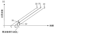
- the beat frequencies (31, 32) of the present invention are given by relative delays with the delay of the local light 21 as a reference.
- the beat frequency 31 is the beat frequency ⁇ ( ⁇ 1 ⁇ LO ) of the backscattered light 22 having the delay ⁇ 1 , and is a negative value.
- the beat frequency 31 is the beat frequency ⁇ ( ⁇ 2 ⁇ LO ) of the backscattered light 23 having the delay ⁇ 2 and is a positive value.
- long-distance measurement by setting the delay ⁇ LO of the local light 21 according to a desired measurement point (setting in the vicinity of the measurement point), backscattered light from a long distance can be obtained without increasing the beat frequency. Can be measured.
- the beat frequency 32 ( ⁇ 2 ) of the back scattered light 23 from the far end is the beat frequency 31 (( ⁇ 1 ) (Fig. 3).
- the spatial resolution deterioration due to phase noise is given by ⁇ (t ⁇ ) ⁇ (t ⁇ LO ) in the present invention, but is given by ⁇ (t ⁇ ) ⁇ (t) in the prior art.
- it is determined by the relative delay ⁇ LO but in the prior art, it is determined by the absolute delay ⁇ , so that the spatial resolution deterioration due to the phase noise in long-distance measurement can be suppressed.
- the beat frequency of the beat signal is set as in the prior art. It may be given as an absolute distance.
- the delay optical fiber 5 is used as in the present invention.
- the local light is delayed by, and the beat frequency of the beat signal may be given as a relative delay based on the delay of the local light. Further, it is preferable to adjust the delay amount of the local light according to the position where the reflectance is to be measured.
- the light reflection measuring device has the following advantageous features over the prior art.
- the absolute delay of the optical fiber is assigned to the beat frequency, a broadband receiving system is required for long-distance measurement, but in the present invention, it is assigned to the beat frequency by the relative delay with respect to the delay of the local light. By increasing the delay of the local light, the beat frequency from a long distance is reduced, and a wide band receiving system is not required.
- the beat signal measured based on the time waveform of the phase noise measured by the reference interferometer is digitally resampled (interpolated). After that, the resampled beat signal was spectrally analyzed to measure the reflectance of the fiber.
- the spatial resolution is not deteriorated as much as the conventional technique in long-distance measurement.
- the reflectance of the fiber can be measured only by spectrum analysis of the measured beat signal.
- the light reflection measuring device is An apparatus for measuring the reflectance distribution of an optical fiber to be measured, which comprises one of a frequency sweep light source, an optical branching unit for branching the frequency sweep light output from the frequency sweep light source into two, and one of the frequency sweep light.
- An optical circulator that enters the measurement optical fiber and guides the backscattered light from the measured optical fiber, and the other of the frequency swept light is a local light, and a delaying optical fiber that delays the local light, and
- An optical 90-degree hybrid that combines the backscattered light and the local light delayed by the delay optical fiber, and the in-phase component and the quadrature component of the combined backscattered light and the beat signal of the local light are detected.
- the light reflection measuring device is The beat frequency is determined by the relative delay of the backscattered light based on the delay provided in the local light, the in-phase component and the quadrature component of the beat signal are measured by the optical 90-degree hybrid, and the beat is calculated from the in-phase component and the quadrature component of the beat signal.
- the reflectance of the optical fiber to be measured at the relative delay set by the delay of the local light is measured.
- the light reflection measuring device is The phase noise included in the beat signal is determined by the relative delay of the backscattered light based on the delay provided in the local light, and the delay provided in the local light is increased to be included in the beat signal in the long-distance measurement. Reduce phase noise.
- Frequency sweep light source 2 Optical branching means 3: Delayed optical fiber 4: Optical circulator 5: Optical fiber under test 6: Optical 90 degree hybrid 7-1, 7-2: Balanced type optical receiver 8-1, 8-2 : Electric low-pass filter 9: A/D converter 10: Analysis unit 21: Local light 22, 23: Backscattered light 31, 32: Beat frequency 301: Optical frequency reflection measuring device
Landscapes
- Physics & Mathematics (AREA)
- Electromagnetism (AREA)
- Engineering & Computer Science (AREA)
- Computer Networks & Wireless Communication (AREA)
- Signal Processing (AREA)
- General Physics & Mathematics (AREA)
- Testing Of Optical Devices Or Fibers (AREA)
- Length Measuring Devices By Optical Means (AREA)
- Optical Transform (AREA)
Abstract
長距離測定を行う場合であっても、広帯域な受信系を用いることなく、位相雑音による空間分解能劣化の少ない反射率分布を測定できる光周波数反射計測装置およびその計測方法を提供することを目的とする。 本発明に係る光周波数反射計測装置は、ローカル光を所定時間遅延させる遅延用光ファイバを備え、被測定光ファイバからの後方散乱光と遅延用光ファイバによって遅延させたローカル光とを合波することにより得られるビート信号の同相成分と直交成分とを測定することで、被測定光ファイバからの後方散乱光のローカル光に対する相対的な遅延の情報とビート周波数の正負の情報とを取得し、これらの情報に基づいて被測定光ファイバの長手方向の反射率分布を求める。
Description
本開示は、光周波数反射計測(OFDR:Optical Frequency Domain Reflectometry)に関する。
光ファイバ反射計測技術として、非特許文献1(以下、従来技術1と呼ぶ)記載の光周波数反射計測技術(以下、OFDRと呼ぶ)が確立されている。OFDRでは、光周波数を線形掃引できる周波数掃引光源を用いる。周波数掃引光をプローブ光とローカル光に2分岐し、プローブ光を光ファイバに入射することで発生する光ファイバからの後方散乱光とローカル光のビート信号を測定する。後方散乱光はローカル光に対して、時間的に遅延したレプリカであるため、距離zからの後方散乱光とローカル光のビート周波数fbeatは
fbeat = γ2z/c
で与えられる。ここで、γは周波数掃引速度、cは光ファイバ中の光速、2z/cは距離zからの後方散乱光のローカル光に対する遅延を表す。
fbeat = γ2z/c
で与えられる。ここで、γは周波数掃引速度、cは光ファイバ中の光速、2z/cは距離zからの後方散乱光のローカル光に対する遅延を表す。
周波数掃引光源を使うため、光帯域を容易に広帯域化でき、非特許文献2(以下、従来技術2と呼ぶ)では、22μmの空間分解能が報告されている。レーザの位相雑音起因の周波数掃引非線形性が空間分解能を劣化させる要因ではあるが、非特許文献3(以下、従来技術3と呼ぶ)では、信号処理によって非線形性を補償することで、空間分解能を劣化させることなく40kmの長距離測定が報告されている。
W. Eickhoff and R. Ulrich. "Optical frequency domain reflectometry in single modefiber," Appl. Phys. Lett., vol. 39, 1981.
B. J. Soller et al., "High resolution optical frequency domain reflectometry for characterization of components and assemblies," Opt. Exp., vol. 13, no. 2, 2005.
X. Fan et al., "Centimeter-level spatial resolution over 40 km realized by bandwidth-division phase-noise-compensated OFDR," Opt. Exp., vol. 19, no. 20, 2011.
従来方式における距離は絶対的な距離であり、絶対的な距離を係数γ2/cでビート周波数に割り当てている。このため、従来方式には、長距離からの後方散乱光のビート周波数は高くなり、広帯域な受信系が必要という課題があった。さらに、従来方式には、長距離測定においては空間分解能劣化を防ぐためにレーザの位相雑音を補償する信号処理が必要であり、その処理時間のために計測時間が長くなるという課題があった。
そこで、本発明は、上記課題を解決するために、長距離測定を行う場合であっても、広帯域な受信系を用いることなく、位相雑音による空間分解能劣化の少ない反射率分布を測定できる光周波数反射計測装置およびその計測方法を提供することを目的とする。
上記目的を達成するために、本発明に係る光周波数反射計測装置およびその計測方法は、絶対的な距離にビート周波数を割り当てるのではなく、参照となる距離を基準とした相対距離にビート周波数を割り当てることとした。
具体的には、本発明に係る光周波数反射計測装置は、
被測定光ファイバの長手方向にある任意点を基準とするようにローカル光を遅延する遅延光ファイバと、
前記遅延光ファイバで遅延された前記ローカル光に対する後方散乱光の相対遅延で、前記ローカル光と前記後方散乱光とのビート信号のビート周波数を表現する解析部と、
を備えることを特徴とする。
被測定光ファイバの長手方向にある任意点を基準とするようにローカル光を遅延する遅延光ファイバと、
前記遅延光ファイバで遅延された前記ローカル光に対する後方散乱光の相対遅延で、前記ローカル光と前記後方散乱光とのビート信号のビート周波数を表現する解析部と、
を備えることを特徴とする。
具体的には、本発明に係る光周波数反射計測方法は、OFDRで、
被測定光ファイバの長手方向にある任意点を基準とするようにローカル光を遅延光ファイバで遅延し、前記遅延光ファイバで遅延された前記ローカル光に対する後方散乱光の相対遅延で、前記ローカル光と前記後方散乱光とのビート信号のビート周波数を表現することを特徴とする。
被測定光ファイバの長手方向にある任意点を基準とするようにローカル光を遅延光ファイバで遅延し、前記遅延光ファイバで遅延された前記ローカル光に対する後方散乱光の相対遅延で、前記ローカル光と前記後方散乱光とのビート信号のビート周波数を表現することを特徴とする。
本発明に係る光周波数反射計測装置及びその計測方法は、ローカル光を遅延し、参照となる距離を長くすることで、長距離測定においてもビート周波数を高くすることなく測定を実現できる。また信号処理を行うことなくレーザの位相雑音による空間分解能劣化を抑制することができる。
従って、本発明は、長距離測定を行う場合であっても、広帯域な受信系を用いることなく、位相雑音による空間分解能劣化の少ない反射率分布を測定できる光周波数反射計測装置およびその計測方法を提供することができる。
本発明に係る光周波数反射計測装置及びその計測方法は、光90度ハイブリッドで前記ローカル光と前記後方散乱光とを合波し、前記ビート信号を生成し、前記光90度ハイブリッドから前記ビート信号の同相成分と直交成分を取得し、前記同相成分と前記直交成分とから前記ビート信号のビート周波数の正負を判断し、前記後方散乱光が発生した被測定光ファイバの長手方向の位置を特定することを特徴とする。
本発明に係る光周波数反射計測装置及びその計測方法は、前記光90度ハイブリッドからの前記ビート信号の同相成分と直交成分をA/D変換する前に、前記光90度ハイブリッドからの前記ビート信号の同相成分と直交成分から前記A/D変換器のナイキスト周波数を超えるビート周波数を低減することを特徴とする。エイリアシングの発生を抑制してノイズを低減できる。
本発明に係る光周波数反射計測装置及びその計測方法は、被測定光ファイバの測定対象となる位置に応じて前記遅延光ファイバの遅延量を変更することを特徴とする。長距離測定においては、ローカル光の遅延を大きくすることで、ビート周波数が高くなることなく長距離からの後方散乱光を測定できる。
本発明は、長距離測定を行う場合であっても、広帯域な受信系を用いることなく、位相雑音による空間分解能劣化の少ない反射率分布を測定できる光周波数反射計測装置およびその計測方法を提供することができる。
添付の図面を参照して本発明の実施形態を説明する。以下に説明する実施形態は本発明の実施例であり、本発明は、以下の実施形態に制限されるものではない。なお、本明細書及び図面において符号が同じ構成要素は、相互に同一のものを示すものとする。
図1は、本実施形態の光周波数反射計測装置301を説明する図である。1は周波数掃引光源、2は光分岐手段、3は遅延光ファイバ、4は光サーキュレータ、5は被測定光ファイバ、6は光90度ハイブリッド、7-1と7-2はバランス型受光器、8-1と8-2は電気ローパスフィルタ、9はA/D変換器、10は解析部を表す。
周波数掃引光源1から出力された周波数掃引光は光分岐手段2によって2分岐され、一方は光サーキュレータ4に伝搬するプローブ光として分岐され、もう一方は遅延用光ファイバ3を伝搬し、光90度ハイブリッド6に伝搬するローカル光として分岐される。光サーキュレータ5を介して被測定光ファイバ5に入射したプローブ光は、被測定光ファイバ5を構成する散乱体によって後方散乱される。後方散乱された光は、被測定光ファイバ5の各位置からの後方散乱光の重ね合わせであり、信号光として光サーキュレータ5を介して光90度ハイブリッド6に伝搬する。ローカル光と信号光は光90度ハイブリッド6で合波され、そのビート信号の同相成分と直交成分がそれぞれバランス型受光器7-1と7-2によって検出される。検出されたビート信号の同相成分と直行成分に含まれる不要な高周波はそれぞれローパスフィルタ8-1と8-2で除去される。ローパスフィルタで高周波除去されたビート信号の同相成分と直交成分がA/D変換器9によって数値化(デジタル化)される。測定されたビート信号の同相成分と直交成分は解析部10において、解析され、被測定光ファイバの反射率が測定される。
遅延用光ファイバ3は、被測定光ファイバ5の長手方向にある任意点を基準とするようにローカル光を遅延する。解析部10は、遅延光ファイバ3で遅延された前記ローカル光に対する後方散乱光の相対遅延で、前記ローカル光と前記後方散乱光とのビート信号のビート周波数を表現する。
光周波数反射計測装置301が、遅延用光ファイバ3の長さを相対距離の基準とし、相対距離における被測定光ファイバ5の反射率を測定できることを説明する。そして、従来技術に対して光周波数反射計測装置301が長距離測定において、ビート周波数を高くすることなく測定を実現し、また信号処理を行うことなくレーザの位相雑音による空間分解能劣化を抑制することを説明する。
周波数掃引光源1から出射する光電界波形E(t)を次式で表す。

ここで、ν0は周波数掃引開始時刻における光周波数、γは周波数掃引速度、θ(t)は光源の位相雑音を表す。ローカル光は長さzLOの遅延用光ファイバを伝搬することで、その電界波形ELO(t)は次式で表される。

ここで、τLOは遅延用光ファイバの伝搬による遅延、cは光ファイバ中の光速を表す。一方、被測定光ファイバからの後方散乱光ESIG (t)は各距離zからの後方散乱光の重ね合わせであり、次式で表される。

ここで、τは距離zの往復伝搬による遅延、R(τ)は遅延τにおける光反射率を表す。
(2)式で与えられるローカル光と(3)式で表される後方散乱光は光90度ハイブリッド6で合波され、ビート信号ESIG
*(t)・ELO(t)の同相成分I(t)と直交成分Q(t)がバランス型受光器(7-1、7-2)で検出される。



(4)式はビート信号がローカル光の遅延τLOを基準とした相対的な遅延τ-τLOでビート周波数γ(τ-τLO)が定められる振幅√R(τ)の波の重ね合わせであることを表す。ビート周波数の正負を見分けるために(6)式で表されるビート信号ESIG
*(t)・ELO(t)の同相成分I(t)と直交成分Q(t)から解析信号S(t)を生成する。

(7)式をフーリエ変換し、ビート周波数領域おける解析信号の表式を得る。ここでは簡単のために、(4)式の位相雑音の項θ(t-τ)-θ(t-τLO)は考慮しない。

ここでfはビート周波数を表す。
(8)式はビート周波数領域における標本化関数δ[2π{γ(τ-τLO)-f}]で複素振幅√R(τ)exp[jφ(τ)]を標本化することを表す。(4)式の位相雑音の項θ(t-τ)-θ(t-τLO)は考慮しなかったが、この位相雑音の項は標本化関数の幅を広げる効果を持つ。
(8)式はビート周波数γ(τ-τLO)に複素振幅√R(τ)exp[jφ(τ)]が割り当てられることを表し、絶対的な遅延τにおける複素振幅√R(τ)exp[jφ(τ)]を相対的な遅延ττ-τLOで表すことを意味する。相対的な遅延の大きさ|τ-τLO|が大きくなるほど(相対的な遅延の基準τLOから離れるほど)ビート周波数は大きくなる。
A/D変換器9のナイキスト周波数を超えるビート周波数はエイリアシングを発生させ、折り返しノイズとなる。これを防ぐためにアンチエイリアスフィルタとしてローパスフィルタ8-1と8-2で(8)式に含まれるビート周波数のうち、低周波のみを抽出する。A/D変換器9のサンプリングレートをfsamとすると、A/D変換器9のナイキスト周波数はfsam/2であり、エイリアシングを発生させない条件は次式で与えられる。

(9)式を満たすようにローパスフィルタ8-1と8-2のカットオフ周波数を設定すればエイリアシングを防ぐことができる。
本発明と従来技術を比較する。従来技術では(4)式においてτLO=0の場合であり、さらにビート信号の成分の同相成分のみを測定するため、(4)-(5)式から、測定されるビート信号S’(t)は次式で表される。


(10)式はビート信号が被測定ファイバの絶対的な遅延τでビート周波数γτが定められる振幅√R(τ)の波の重ね合わせであることを表す。(10)式のスペクトルを解析することで、ビート周波数γτに反射率R(τ)を持つスペクトルを得ることができ、このスペクトルは絶対遅延τに反射率R(τ)を持つ被測定ファイバの反射率を表す。
(7)式と(10)式を比較すると、図2に示すように、本発明のビート周波数(31、32)はローカル光21の遅延を基準とした相対遅延で与えられる。ビート周波数31は、遅延τ1の後方散乱光22のビート周波数γ(τ1-τLO)であり、負の値である。ビート周波数31は、遅延τ2の後方散乱光23のビート周波数γ(τ2-τLO)であり、正の値である。長距離測定においては、所望の測定点に応じてローカル光21の遅延τLOを設定する(当該測定点近傍に設定する)ことで、ビート周波数が高くなることなく遠距離からの後方散乱光を測定できる。また、ビート周波数の正負より、設定した遅延より遠端側の後方散乱光なのか近端側の後方散乱光なのかを判断することができる。一方、従来技術では、ビート周波数は被測定ファイバの絶対遅延で与えられるため、遠端からの後方散乱光23のビート周波数32(γτ2)は近端からの後方散乱光22のビート周波数31(γτ1)より高くなる(図3)。
また位相雑音による空間分解能劣化について、本発明ではθ(t-τ)-θ(t-τLO)で与えられるが、従来技術ではθ(t-τ)-θ(t)で与えられる。2つの位相雑音の間の相対的な遅延量が大きいほど、空間分解能が劣化する。本発明では相対遅延τ-τLOで決定するが、従来技術では絶対遅延τで決定するため、長距離測定における位相雑音による空間分解能劣化を抑制することができる。
被測定光ファイバ5が短い、あるいは被測定光ファイバ5の近端側(プローブ光の入射端に近い側)の領域の反射率を測定する場合は、従来技術のようにビート信号のビート周波数を絶対的な距離で与えてもよい。しかし、被測定光ファイバ5が長い、あるいは被測定光ファイバ5の遠端側(プローブ光の入射端から遠い側)の領域の反射率を測定する場合は、本発明のように遅延光ファイバ5でローカル光を遅延し、ビート信号のビート周波数をローカル光の遅延を基準とした相対遅延で与えるとよい。また、反射率を測定しようとする位置に応じてローカル光の遅延量を調整することが好ましい。
(発明の効果)
本発明に係る光反射計測装置は、従来技術に対して以下の有利な特徴を持つ。
本発明に係る光反射計測装置は、従来技術に対して以下の有利な特徴を持つ。
従来技術1~3では、光ファイバの絶対遅延をビート周波数に割り当てるため、長距離測定では広帯域な受信系が求められるが、本発明では、ローカル光の遅延との相対遅延でビート周波数に割り当てる。ローカル光の遅延を長くすることで、長距離からのビート周波数を落とし、広帯域な受信系を必要としない。
従来技術3では、絶対遅延で位相雑音による空間分解能が劣化するため、参照干渉計で測定した位相雑音の時間波形を元に測定されたビート信号がデジタル上でリサンプリング(補間)する信号処理を行った後、リサンプリングされたビート信号をスペクトル解析し、ファイバの反射率を測定していた。本発明では、相対遅延で位相雑音による空間分解能が劣化するため、長距離測定においては、従来技術で発生するほどの空間分解能劣化が発生しない。測定されたビート信号をスペクトル解析のみでファイバの反射率を測定することができる。
[付記]
以下は、本発明に係る光反射計測装置を説明したものである。
以下は、本発明に係る光反射計測装置を説明したものである。
(1):本発明に係る光反射計測装置は、
被測定光ファイバの反射率分布を測定する装置であって、周波数掃引光源と、前記周波数掃引光源が出力する周波数掃引光を2分岐する光分岐手段と、前記周波数掃引光の一方のうち、被測定光ファイバに入射し、被測定光ファイバからの後方散乱光を導波させる光サーキュレータと、前記周波数掃引光のもう一方をローカル光とし、前記ローカル光に遅延を与える遅延用光ファイバと、前記後方散乱光と前記遅延用光ファイバで遅延を与えられたローカル光を合波する光90度ハイブリッドと、前記合波された後方散乱光とローカル光のビート信号の同相成分と直交成分を検出し、出力する手段と、前記出力されたビート信号の同相成分と直交成分に含まれる高周波を除去するローパスフィルタと、前記ローパスフィルタによって高周波が除去されたビート信号の同相成分と直交成分をA/D変換するA/D変換器と、前記A/D変換されたビート信号の同相成分と直交成分からスペクトルを解析する解析部から構成される。
被測定光ファイバの反射率分布を測定する装置であって、周波数掃引光源と、前記周波数掃引光源が出力する周波数掃引光を2分岐する光分岐手段と、前記周波数掃引光の一方のうち、被測定光ファイバに入射し、被測定光ファイバからの後方散乱光を導波させる光サーキュレータと、前記周波数掃引光のもう一方をローカル光とし、前記ローカル光に遅延を与える遅延用光ファイバと、前記後方散乱光と前記遅延用光ファイバで遅延を与えられたローカル光を合波する光90度ハイブリッドと、前記合波された後方散乱光とローカル光のビート信号の同相成分と直交成分を検出し、出力する手段と、前記出力されたビート信号の同相成分と直交成分に含まれる高周波を除去するローパスフィルタと、前記ローパスフィルタによって高周波が除去されたビート信号の同相成分と直交成分をA/D変換するA/D変換器と、前記A/D変換されたビート信号の同相成分と直交成分からスペクトルを解析する解析部から構成される。
(2):本発明に係る光反射計測装置は、
ローカル光に設けた遅延を基準とした後方散乱光の相対遅延でビート周波数が決まり、光90度ハイブリッドでビート信号の同相成分と直交成分を測定し、前記ビート信号の同相成分と直交成分からビート信号の解析信号を生成し、前記解析信号の周波数の正負の符号を見分けることで、前記ローカル光の遅延で設定された相対遅延における被測定光ファイバの反射率を測定する。
ローカル光に設けた遅延を基準とした後方散乱光の相対遅延でビート周波数が決まり、光90度ハイブリッドでビート信号の同相成分と直交成分を測定し、前記ビート信号の同相成分と直交成分からビート信号の解析信号を生成し、前記解析信号の周波数の正負の符号を見分けることで、前記ローカル光の遅延で設定された相対遅延における被測定光ファイバの反射率を測定する。
(3):本発明に係る光反射計測装置は、
前記ローカル光に設けた遅延を基準とした後方散乱光の相対遅延でビート信号に含まれる位相雑音が決まり、前記ローカル光に設けた遅延を長くすることで、長距離測定におけるビート信号に含まれる位相雑音を低減する。
前記ローカル光に設けた遅延を基準とした後方散乱光の相対遅延でビート信号に含まれる位相雑音が決まり、前記ローカル光に設けた遅延を長くすることで、長距離測定におけるビート信号に含まれる位相雑音を低減する。
1:周波数掃引光源
2:光分岐手段
3:遅延光ファイバ
4:光サーキュレータ
5:被測定光ファイバ
6:光90度ハイブリッド
7-1、7-2:バランス型受光器
8-1、8-2:電気ローパスフィルタ
9:A/D変換器
10:解析部
21:ローカル光
22、23:後方散乱光
31、32:ビート周波数
301:光周波数反射計測装置
2:光分岐手段
3:遅延光ファイバ
4:光サーキュレータ
5:被測定光ファイバ
6:光90度ハイブリッド
7-1、7-2:バランス型受光器
8-1、8-2:電気ローパスフィルタ
9:A/D変換器
10:解析部
21:ローカル光
22、23:後方散乱光
31、32:ビート周波数
301:光周波数反射計測装置
Claims (8)
- 被測定光ファイバの長手方向にある任意点を基準とするようにローカル光を遅延する遅延光ファイバと、
前記遅延光ファイバで遅延された前記ローカル光に対する後方散乱光の相対遅延で、前記ローカル光と前記後方散乱光とのビート信号のビート周波数を表現する解析部と、
を備えることを特徴とする光周波数反射計測(OFDR:Optical Frequency Domain Reflectometry)装置。 - 前記ローカル光と前記後方散乱光とを合波し、前記ビート信号を生成する光90度ハイブリッドをさらに備え、
前記解析部は、
前記光90度ハイブリッドから前記ビート信号の同相成分と直交成分を取得し、前記同相成分と前記直交成分とから前記ビート信号のビート周波数の正負を判断し、前記後方散乱光が発生した被測定光ファイバの長手方向の位置を特定することを特徴とする請求項1に記載のOFDR装置。 - 前記光90度ハイブリッドからの前記ビート信号の同相成分と直交成分をA/D変換するA/D変換器と、
前記光90度ハイブリッドからの前記ビート信号の同相成分と直交成分から前記A/D変換器のナイキスト周波数を超えるビート周波数を低減して、前記A/D変換器へ入力するローパスフィルタと、
をさらに備えることを特徴とする請求項2に記載のOFDR装置。 - 前記遅延光ファイバの遅延量を変更する遅延量可変機構をさらに備えることを特徴とする請求項1から3のいずれかに記載のOFDR装置。
- 光周波数反射計測(OFDR:Optical Frequency Domain Reflectometry)で、
被測定光ファイバの長手方向にある任意点を基準とするようにローカル光を遅延光ファイバで遅延し、
前記遅延光ファイバで遅延された前記ローカル光に対する後方散乱光の相対遅延で、前記ローカル光と前記後方散乱光とのビート信号のビート周波数を表現する
ことを特徴とする計測方法。 - 光90度ハイブリッドで前記ローカル光と前記後方散乱光とを合波し、前記ビート信号を生成し、
前記光90度ハイブリッドから前記ビート信号の同相成分と直交成分を取得し、前記同相成分と前記直交成分とから前記ビート信号のビート周波数の正負を判断し、前記後方散乱光が発生した被測定光ファイバの長手方向の位置を特定することを特徴とする請求項5に記載の計測方法。 - 前記光90度ハイブリッドからの前記ビート信号の同相成分と直交成分をA/D変換する前に、
前記光90度ハイブリッドからの前記ビート信号の同相成分と直交成分からA/D変換器のナイキスト周波数を超えるビート周波数を低減することを特徴とする請求項6に記載の計測方法。 - 被測定光ファイバの測定対象となる位置に応じて前記遅延光ファイバの遅延量を変更することを特徴とする請求項5から7のいずれかに記載の計測方法。
Priority Applications (1)
| Application Number | Priority Date | Filing Date | Title |
|---|---|---|---|
| US17/430,016 US11463163B2 (en) | 2019-02-12 | 2020-01-29 | Device for measuring optical frequency reflection and measurement method thereof |
Applications Claiming Priority (2)
| Application Number | Priority Date | Filing Date | Title |
|---|---|---|---|
| JP2019022953A JP7331373B2 (ja) | 2019-02-12 | 2019-02-12 | 光周波数反射計測装置およびその計測方法 |
| JP2019-022953 | 2019-02-12 |
Publications (1)
| Publication Number | Publication Date |
|---|---|
| WO2020166331A1 true WO2020166331A1 (ja) | 2020-08-20 |
Family
ID=72045605
Family Applications (1)
| Application Number | Title | Priority Date | Filing Date |
|---|---|---|---|
| PCT/JP2020/003108 Ceased WO2020166331A1 (ja) | 2019-02-12 | 2020-01-29 | 光周波数反射計測装置およびその計測方法 |
Country Status (3)
| Country | Link |
|---|---|
| US (1) | US11463163B2 (ja) |
| JP (1) | JP7331373B2 (ja) |
| WO (1) | WO2020166331A1 (ja) |
Cited By (2)
| Publication number | Priority date | Publication date | Assignee | Title |
|---|---|---|---|---|
| CN112798025A (zh) * | 2021-03-19 | 2021-05-14 | 武汉昊衡科技有限公司 | 提高ofdr测量空间分辨率的方法及ofdr系统 |
| EP4215894A4 (en) * | 2020-09-15 | 2024-05-22 | Nippon Telegraph And Telephone Corporation | APPARATUS AND METHOD FOR OPTICAL FREQUENCY DOMAIN REFLECTOMETRY |
Families Citing this family (1)
| Publication number | Priority date | Publication date | Assignee | Title |
|---|---|---|---|---|
| CN115235367B (zh) * | 2022-07-26 | 2023-04-25 | 北京理工大学 | 一种大应变测量范围的高精度双频光频域反射仪 |
Citations (8)
| Publication number | Priority date | Publication date | Assignee | Title |
|---|---|---|---|---|
| JP2003322588A (ja) * | 2002-03-01 | 2003-11-14 | Nippon Telegr & Teleph Corp <Ntt> | 反射式ブリルアンスペクトル分布測定方法および装置 |
| JP2003322589A (ja) * | 2002-03-01 | 2003-11-14 | Nippon Telegr & Teleph Corp <Ntt> | ブリルアンスペクトル分布測定方法および装置 |
| EP2110646A2 (de) * | 2008-04-16 | 2009-10-21 | BAM Bundesanstalt für Materialforschung und -prüfung | Vorrichtung und Verfahren zur Brillouin-Frequenzbereichsanalyse |
| JP2013195225A (ja) * | 2012-03-19 | 2013-09-30 | Anritsu Corp | ブリルアンゲインスペクトル測定装置及び方法 |
| US20140176937A1 (en) * | 2011-08-18 | 2014-06-26 | Tiegen Liu | Distributed disturbance sensing device and the related demodulation method based on polarization sensitive optical frequency domain reflectometry |
| JP2014209685A (ja) * | 2013-04-16 | 2014-11-06 | 日本電信電話株式会社 | マルチキャリア光送信器及びマルチキャリア光送信方法 |
| WO2017115459A1 (ja) * | 2015-12-28 | 2017-07-06 | パナソニックIpマネジメント株式会社 | センサ、およびセンサを用いた水栓装置 |
| JP2018146371A (ja) * | 2017-03-06 | 2018-09-20 | 日本電信電話株式会社 | 温度・歪センシング装置及び温度・歪センシング方法 |
Family Cites Families (13)
| Publication number | Priority date | Publication date | Assignee | Title |
|---|---|---|---|---|
| JPH10148596A (ja) * | 1996-11-15 | 1998-06-02 | Nippon Telegr & Teleph Corp <Ntt> | 光反射測定回路 |
| JP3513432B2 (ja) * | 1999-07-27 | 2004-03-31 | 三菱重工業株式会社 | 光周波数領域反射測定装置および光周波数領域反射測定方法 |
| CN101031788B (zh) * | 2005-09-22 | 2011-06-15 | 日本电信电话株式会社 | 光波导的色散测定方法、测定装置 |
| WO2008105322A1 (ja) * | 2007-02-28 | 2008-09-04 | Nippon Telegraph And Telephone Corporation | 光リフレクトメトリ測定方法および装置 |
| DE102009043546A1 (de) * | 2009-09-30 | 2011-03-31 | Lios Technology Gmbh | Verfahren und Vorrichtung zur ortsaufgelösten Messung mechanischer Größen, insbesondere mechanischer Schwingungen |
| US9683928B2 (en) * | 2013-06-23 | 2017-06-20 | Eric Swanson | Integrated optical system and components utilizing tunable optical sources and coherent detection and phased array for imaging, ranging, sensing, communications and other applications |
| JP6374985B2 (ja) * | 2014-04-28 | 2018-08-15 | オプトプラン・アー・エス | 干渉計型光ファイバセンサシステムおよびインテロゲーションの方法 |
| EP3219027B1 (en) * | 2014-11-16 | 2019-10-16 | Dsit Solutions Ltd. | Spectrally efficient optical frequency-domain reflectometry using i/q detection |
| IL243731B (en) * | 2016-01-23 | 2021-01-31 | Dsit Solutions Ltd | Optical reflectometry in the frequency plane by non-linear frequency scanning |
| US10670389B2 (en) * | 2017-02-23 | 2020-06-02 | General Photonics Corporation | Sensitive optical fiber shape sensing based on shape-related optical polarization evolution |
| JPWO2020027223A1 (ja) * | 2018-07-31 | 2021-09-24 | 古河電気工業株式会社 | ケーブル、ケーブルの形状センシングシステム、センシングシステム、ケーブル形状のセンシング方法 |
| JP6773091B2 (ja) * | 2018-09-07 | 2020-10-21 | 横河電機株式会社 | 光ファイバ特性測定装置及び光ファイバ特性測定方法 |
| JP2020063971A (ja) * | 2018-10-17 | 2020-04-23 | 横河電機株式会社 | 光ファイバ特性測定装置及び光ファイバ特性測定方法 |
-
2019
- 2019-02-12 JP JP2019022953A patent/JP7331373B2/ja active Active
-
2020
- 2020-01-29 US US17/430,016 patent/US11463163B2/en active Active
- 2020-01-29 WO PCT/JP2020/003108 patent/WO2020166331A1/ja not_active Ceased
Patent Citations (8)
| Publication number | Priority date | Publication date | Assignee | Title |
|---|---|---|---|---|
| JP2003322588A (ja) * | 2002-03-01 | 2003-11-14 | Nippon Telegr & Teleph Corp <Ntt> | 反射式ブリルアンスペクトル分布測定方法および装置 |
| JP2003322589A (ja) * | 2002-03-01 | 2003-11-14 | Nippon Telegr & Teleph Corp <Ntt> | ブリルアンスペクトル分布測定方法および装置 |
| EP2110646A2 (de) * | 2008-04-16 | 2009-10-21 | BAM Bundesanstalt für Materialforschung und -prüfung | Vorrichtung und Verfahren zur Brillouin-Frequenzbereichsanalyse |
| US20140176937A1 (en) * | 2011-08-18 | 2014-06-26 | Tiegen Liu | Distributed disturbance sensing device and the related demodulation method based on polarization sensitive optical frequency domain reflectometry |
| JP2013195225A (ja) * | 2012-03-19 | 2013-09-30 | Anritsu Corp | ブリルアンゲインスペクトル測定装置及び方法 |
| JP2014209685A (ja) * | 2013-04-16 | 2014-11-06 | 日本電信電話株式会社 | マルチキャリア光送信器及びマルチキャリア光送信方法 |
| WO2017115459A1 (ja) * | 2015-12-28 | 2017-07-06 | パナソニックIpマネジメント株式会社 | センサ、およびセンサを用いた水栓装置 |
| JP2018146371A (ja) * | 2017-03-06 | 2018-09-20 | 日本電信電話株式会社 | 温度・歪センシング装置及び温度・歪センシング方法 |
Cited By (3)
| Publication number | Priority date | Publication date | Assignee | Title |
|---|---|---|---|---|
| EP4215894A4 (en) * | 2020-09-15 | 2024-05-22 | Nippon Telegraph And Telephone Corporation | APPARATUS AND METHOD FOR OPTICAL FREQUENCY DOMAIN REFLECTOMETRY |
| CN112798025A (zh) * | 2021-03-19 | 2021-05-14 | 武汉昊衡科技有限公司 | 提高ofdr测量空间分辨率的方法及ofdr系统 |
| CN112798025B (zh) * | 2021-03-19 | 2021-08-10 | 武汉昊衡科技有限公司 | 提高ofdr测量空间分辨率的方法及ofdr系统 |
Also Published As
| Publication number | Publication date |
|---|---|
| US20220149934A1 (en) | 2022-05-12 |
| JP7331373B2 (ja) | 2023-08-23 |
| JP2020134143A (ja) | 2020-08-31 |
| US11463163B2 (en) | 2022-10-04 |
Similar Documents
| Publication | Publication Date | Title |
|---|---|---|
| JP6552983B2 (ja) | ブリルアン散乱測定方法およびブリルアン散乱測定装置 | |
| JP6277147B2 (ja) | 光ファイバ振動測定方法及びシステム | |
| CN106500970B (zh) | 光纤特性测定装置 | |
| JPWO2003005002A1 (ja) | 伝搬測定装置及び伝搬測定方法 | |
| JP7331373B2 (ja) | 光周波数反射計測装置およびその計測方法 | |
| WO2014002564A1 (ja) | 風計測コヒーレントライダ装置 | |
| US7385932B2 (en) | Wideband frequency domain reflectometry to determine the nature and location of subscriber line faults | |
| JP5582473B2 (ja) | 光周波数領域反射測定方法及び光周波数領域反射測定装置 | |
| EP4460679B1 (en) | Optical measurement system | |
| JP2014045096A (ja) | レーザ位相雑音測定装置及びその測定方法 | |
| JP7069993B2 (ja) | 光スペクトル線幅演算方法、装置およびプログラム | |
| EP2799838B1 (en) | Information signal generating method | |
| JP6751379B2 (ja) | 光時間領域反射測定方法および光時間領域反射測定装置 | |
| JP7554801B2 (ja) | Ofdrシステム | |
| CN106768895A (zh) | 一种单、多模光纤量程自适应的检测方法 | |
| JP7586337B2 (ja) | 光パルス試験方法及び光パルス試験装置 | |
| JP7367879B2 (ja) | 光周波数領域反射計測装置及び方法 | |
| JP2023044915A (ja) | 分布型光ファイバ歪み測定装置及び分布型光ファイバ歪み測定方法 | |
| CN114486202A (zh) | 一种简单易调的色散超快测量系统及方法 | |
| JP6751378B2 (ja) | 光時間領域反射測定方法および光時間領域反射測定装置 | |
| JP6347552B2 (ja) | 光学デバイスのインパルスレスポンス測定装置および測定方法 | |
| WO2026100060A1 (ja) | データ処理システム | |
| WO2026018331A1 (ja) | 解析処理システム | |
| Saitoh | High accuracy OFDR by coherence compensation method | |
| JP7380382B2 (ja) | 測距計 |
Legal Events
| Date | Code | Title | Description |
|---|---|---|---|
| 121 | Ep: the epo has been informed by wipo that ep was designated in this application |
Ref document number: 20756035 Country of ref document: EP Kind code of ref document: A1 |
|
| NENP | Non-entry into the national phase |
Ref country code: DE |
|
| 122 | Ep: pct application non-entry in european phase |
Ref document number: 20756035 Country of ref document: EP Kind code of ref document: A1 |