EP3219027B1 - Spectrally efficient optical frequency-domain reflectometry using i/q detection - Google Patents
Spectrally efficient optical frequency-domain reflectometry using i/q detection Download PDFInfo
- Publication number
- EP3219027B1 EP3219027B1 EP15859673.4A EP15859673A EP3219027B1 EP 3219027 B1 EP3219027 B1 EP 3219027B1 EP 15859673 A EP15859673 A EP 15859673A EP 3219027 B1 EP3219027 B1 EP 3219027B1
- Authority
- EP
- European Patent Office
- Prior art keywords
- optical
- signal
- fiber
- complex
- frequency
- Prior art date
- Legal status (The legal status is an assumption and is not a legal conclusion. Google has not performed a legal analysis and makes no representation as to the accuracy of the status listed.)
- Active
Links
- 238000001514 detection method Methods 0.000 title claims description 46
- 238000002168 optical frequency-domain reflectometry Methods 0.000 title description 13
- 230000003287 optical effect Effects 0.000 claims description 97
- 239000013307 optical fiber Substances 0.000 claims description 44
- 238000000034 method Methods 0.000 claims description 26
- 238000002310 reflectometry Methods 0.000 claims description 23
- 230000004044 response Effects 0.000 claims description 8
- 230000007123 defense Effects 0.000 claims description 7
- 238000004891 communication Methods 0.000 claims description 5
- 230000000737 periodic effect Effects 0.000 claims description 5
- 239000000835 fiber Substances 0.000 description 54
- 230000035559 beat frequency Effects 0.000 description 15
- 238000012545 processing Methods 0.000 description 14
- 230000006870 function Effects 0.000 description 13
- 238000004458 analytical method Methods 0.000 description 7
- 238000000253 optical time-domain reflectometry Methods 0.000 description 4
- 230000001427 coherent effect Effects 0.000 description 3
- 238000005516 engineering process Methods 0.000 description 3
- 238000012544 monitoring process Methods 0.000 description 3
- 230000008901 benefit Effects 0.000 description 2
- 230000000593 degrading effect Effects 0.000 description 2
- 238000010586 diagram Methods 0.000 description 2
- 238000004088 simulation Methods 0.000 description 2
- 238000003491 array Methods 0.000 description 1
- 230000009286 beneficial effect Effects 0.000 description 1
- 230000005540 biological transmission Effects 0.000 description 1
- 238000004364 calculation method Methods 0.000 description 1
- 230000015556 catabolic process Effects 0.000 description 1
- 238000005094 computer simulation Methods 0.000 description 1
- 230000006735 deficit Effects 0.000 description 1
- 238000006731 degradation reaction Methods 0.000 description 1
- 238000013461 design Methods 0.000 description 1
- 230000005284 excitation Effects 0.000 description 1
- 238000005259 measurement Methods 0.000 description 1
- 238000012986 modification Methods 0.000 description 1
- 230000004048 modification Effects 0.000 description 1
- 238000000181 polarisation optical time-domain reflectometry Methods 0.000 description 1
- 238000005070 sampling Methods 0.000 description 1
- 238000010183 spectrum analysis Methods 0.000 description 1
- 230000002123 temporal effect Effects 0.000 description 1
- 238000012360 testing method Methods 0.000 description 1
- 230000001052 transient effect Effects 0.000 description 1
- XLYOFNOQVPJJNP-UHFFFAOYSA-N water Substances O XLYOFNOQVPJJNP-UHFFFAOYSA-N 0.000 description 1
Images


Classifications
-
- G—PHYSICS
- G01—MEASURING; TESTING
- G01M—TESTING STATIC OR DYNAMIC BALANCE OF MACHINES OR STRUCTURES; TESTING OF STRUCTURES OR APPARATUS, NOT OTHERWISE PROVIDED FOR
- G01M11/00—Testing of optical apparatus; Testing structures by optical methods not otherwise provided for
- G01M11/30—Testing of optical devices, constituted by fibre optics or optical waveguides
- G01M11/31—Testing of optical devices, constituted by fibre optics or optical waveguides with a light emitter and a light receiver being disposed at the same side of a fibre or waveguide end-face, e.g. reflectometers
- G01M11/3172—Reflectometers detecting the back-scattered light in the frequency-domain, e.g. OFDR, FMCW, heterodyne detection
-
- G—PHYSICS
- G01—MEASURING; TESTING
- G01M—TESTING STATIC OR DYNAMIC BALANCE OF MACHINES OR STRUCTURES; TESTING OF STRUCTURES OR APPARATUS, NOT OTHERWISE PROVIDED FOR
- G01M11/00—Testing of optical apparatus; Testing structures by optical methods not otherwise provided for
- G01M11/30—Testing of optical devices, constituted by fibre optics or optical waveguides
- G01M11/31—Testing of optical devices, constituted by fibre optics or optical waveguides with a light emitter and a light receiver being disposed at the same side of a fibre or waveguide end-face, e.g. reflectometers
- G01M11/3181—Reflectometers dealing with polarisation
-
- G—PHYSICS
- G01—MEASURING; TESTING
- G01M—TESTING STATIC OR DYNAMIC BALANCE OF MACHINES OR STRUCTURES; TESTING OF STRUCTURES OR APPARATUS, NOT OTHERWISE PROVIDED FOR
- G01M11/00—Testing of optical apparatus; Testing structures by optical methods not otherwise provided for
- G01M11/30—Testing of optical devices, constituted by fibre optics or optical waveguides
- G01M11/33—Testing of optical devices, constituted by fibre optics or optical waveguides with a light emitter being disposed at one fibre or waveguide end-face, and a light receiver at the other end-face
- G01M11/333—Testing of optical devices, constituted by fibre optics or optical waveguides with a light emitter being disposed at one fibre or waveguide end-face, and a light receiver at the other end-face using modulated input signals
-
- H—ELECTRICITY
- H04—ELECTRIC COMMUNICATION TECHNIQUE
- H04B—TRANSMISSION
- H04B10/00—Transmission systems employing electromagnetic waves other than radio-waves, e.g. infrared, visible or ultraviolet light, or employing corpuscular radiation, e.g. quantum communication
- H04B10/07—Arrangements for monitoring or testing transmission systems; Arrangements for fault measurement of transmission systems
- H04B10/071—Arrangements for monitoring or testing transmission systems; Arrangements for fault measurement of transmission systems using a reflected signal, e.g. using optical time domain reflectometers [OTDR]
-
- H—ELECTRICITY
- H04—ELECTRIC COMMUNICATION TECHNIQUE
- H04B—TRANSMISSION
- H04B10/00—Transmission systems employing electromagnetic waves other than radio-waves, e.g. infrared, visible or ultraviolet light, or employing corpuscular radiation, e.g. quantum communication
- H04B10/50—Transmitters
- H04B10/572—Wavelength control
-
- G—PHYSICS
- G01—MEASURING; TESTING
- G01M—TESTING STATIC OR DYNAMIC BALANCE OF MACHINES OR STRUCTURES; TESTING OF STRUCTURES OR APPARATUS, NOT OTHERWISE PROVIDED FOR
- G01M11/00—Testing of optical apparatus; Testing structures by optical methods not otherwise provided for
- G01M11/30—Testing of optical devices, constituted by fibre optics or optical waveguides
- G01M11/39—Testing of optical devices, constituted by fibre optics or optical waveguides in which light is projected from both sides of the fiber or waveguide end-face
Definitions
- the present invention relates generally to fiber-optic reflectometry, and particularly to methods and systems for fiber-optic reflectometry using In-phase/Quadrature (I/Q) detection.
- I/Q In-phase/Quadrature
- Fiber-optic reflectometry techniques are used for detecting and analyzing impairments and events that affect the optical properties of an optical fiber.
- Various fiber-optic reflectometry techniques are known in the art. Such techniques are described, for example, by Takada et al., in "New measurement system for fault location in optical waveguide devices based on an interferometric technique," Applied Optics, volume 26, issue 9, 1987, pages 1603-1606 ; by Bamoski and Jensen, in “Fiber waveguides: a novel technique for investigating attenuation characteristics," Applied Optics, volume 15, issue 9, 1976, pages 2112-2115 ; and by Bar-Am et al., in “OFDR with double interrogation for dynamic quasi-distributed sensing," Optics Express, volume 22, issue 3, 2014, pages 2299-2308 .
- Fiber-optic reflectometry schemes are described by Arbel and Eyal, in “Dynamic optical frequency domain reflectometry,” Optics Express, volume 22, issue 8, 2014, pages 8823-8830 ; and by Zhang and Bao, in “Distributed optical fiber vibration sensor based on spectrum analysis of Polarization-OTDR system,” Optics Express, volume 16, issue 14, 2008, pages 10240-10247 .
- OTDR-based schemes are described, for example, by Juarez et al., in “Distributed fiber-optic intrusion sensor system,” Journal of Lightwave Technology, volume 23, issue 6, 2005, pages 2081-2087 ; and by Yuelan et al., in “Distributed vibration sensor based on coherent detection of phase-OTDR,” Journal of Lightwave Technology, volume 28, issue 22, 2010, pages 3243-3249 .
- OFDR-based schemes are described, for example, in the articles by Bar-Am et al. and by Arbel and Eyal, cited above, as well as by Ito et al., in "Long-range coherent OFDR with light source phase noise compensation," Journal of Lightwave Technology, volume 30, issue 8, 2012, pages 1015-1024 .
- An embodiment of the present invention that is described herein provides a system for fiber-optic reflectometry.
- the system includes an optical source, a beat detection module and a processor.
- the optical source is configured to generate an optical interrogation signal that is transmitted into an optical fiber.
- the beat detection module is configured to receive from the optical fiber an optical backscattering signal in response to the optical interrogation signal, and to mix the optical backscattering signal with a reference replica of the optical interrogation signal using In-phase/Quadrature (I/Q) mixing, so as to produce a complex beat signal having In-phase (I) and Quadrature (Q) components.
- the processor is configured to sense one or more events affecting the optical fiber by analyzing the I and Q components of the complex beat signal.
- the processor is configured to analyze the complex beat signal by defining in the complex beat signal at least: a first time interval, during which an instantaneous frequency of the optical backscattering signal is guaranteed to be lower than the instantaneous frequency of the reference replica; and a second time interval, during which the instantaneous frequency of the optical backscattering signal is guaranteed to be higher than the instantaneous frequency of the reference replica.
- the optical interrogation signal includes a periodic chirp signal.
- the beat detection module includes a 90° optical hybrid configured to perform the I/Q mixing.
- the beat detection module includes a pair of optical detectors that are configured to detect the I and Q components of the complex beat signal.
- the processor is configured to calculate a backscattering profile of the optical fiber by: calculating a first complex frequency-domain transform of the complex beat signal in the first time interval, and retaining only a positive-frequency part of the first complex frequency-domain transform; and calculating a second complex frequency-domain transform of the complex beat signal in the second time interval, and retaining only a negative-frequency part of the second complex frequency-domain transform.
- the processor is configured to sense the events in a first part of the optical fiber based on the first complex frequency-domain transform, and to sense the events in a second part of the optical fiber based on the second complex frequency-domain transform.
- the optical source is configured to generate the optical interrogation signal with a scan repetition rate f scan , wherein a length of the optical fiber is denoted L , wherein a speed of light in the optical fiber is denoted v , and wherein the processor is configured to sense the event while f scan L ⁇ v / 2. In an embodiment, the processor is configured to sense the event while v /4 ⁇ f scan L ⁇ v / 2.
- the optical fiber is part of an optical communication system, and the one or more events include a fault in the optical fiber.
- the optical fiber is part of a perimeter defense system, and the one or more events include a breach of the perimeter defense system.
- the optical fiber is installed in a utility infrastructure, and the one or more events include a fault in the utility infrastructure.
- a method for fiber-optic reflectometry includes transmitting an optical interrogation signal into an optical fiber, receiving from the optical fiber an optical backscattering signal in response to the optical interrogation signal, and mixing the optical backscattering signal with a reference replica of the optical interrogation signal using In-phase/Quadrature (I/Q) mixing, so as to produce a complex beat signal having In-phase (I) and Quadrature (Q) components.
- I/Q In-phase/Quadrature
- One or more events affecting the optical fiber are sensed by analyzing the I and Q components of the complex beat signal.
- a system for fiber-optic reflectometry includes an optical source, a beat detection module and a processor.
- the optical source is configured to generate an optical interrogation signal that is transmitted into an optical fiber.
- the beat detection module is configured to receive from the optical fiber an optical backscattering signal in response to the optical interrogation signal, to mix the optical backscattering signal with a reference replica of the optical interrogation signal so as to produce a beat signal, and to distinguish in the beat signal between (i) a first component in which an instantaneous frequency of the optical backscattering signal is lower than the instantaneous frequency of the reference replica and (ii) a second component in which the instantaneous frequency of the optical backscattering signal is higher than the instantaneous frequency of the reference replica.
- the processor is configured to sense one or more events affecting the optical fiber by analyzing the first and second components of the beat signal.
- a method for fiber-optic reflectometry includes transmitting an optical interrogation signal into an optical fiber, receiving from the optical fiber an optical backscattering signal in response to the optical interrogation signal, and mixing the optical backscattering signal with a reference replica of the optical interrogation signal, so as to produce a beat signal.
- One or more events affecting the optical fiber are sensed by analyzing the first and second components of the beat signal.
- Embodiments of the present invention that are described herein provide improved methods and systems for fiber-optic reflectometry.
- the disclosed techniques can be used for implementing various types of sensors for use in a wide variety of applications.
- Example applications include optical network monitoring, perimeter defense, as well as monitoring of infrastructure such as pipelines, railways and roads, to name just a few.
- an Optical Frequency-Domain Reflectometry (OFDR) system generates an optical interrogation signal into an optical fiber of length L .
- the interrogation signal comprises a periodic optical signal whose instantaneous wavelength varies as a function of time and has a repetition rate f scan .
- a backscattering optical signal is received from the fiber in response to the interrogation signal.
- the system optically mixes the backscattering signal with a reference replica of the interrogation signal to produce a beat signal.
- the system detects and digitizes the beat signal, and transforms it into the frequency domain, so as to produce a frequency-domain backscattering profile of the fiber.
- the system analyzes the backscattering profile depending of the application.
- the fiber length and the scan repetition rate must satisfy f scan L ⁇ v /4, wherein v denotes the speed of light in the fiber.
- f scan L v / 4.
- the optical mixing and subsequent detection are performed using a complex-signal, In-phase/Quadrature (I/Q) receiver scheme.
- the system mixes the backscattering signal with the reference signal using a 90° optical hybrid and detects the beat signal using a pair of balanced optical detectors in quadrature.
- the I/Q detection scheme enables the system to distinguish between positive and negative beat frequencies.
- the upper bound on the product f scan L is doubled relative to real-signal detection.
- the methods and systems described herein use I/Q optical mixing and detection to provide a considerable increase in the achievable scan repetition rate and fiber length, without degradation in spatial resolution or other performance.
- the disclosed techniques are particularly beneficial in dynamic sensing applications i.e., applications that require sensing with a high update rate.
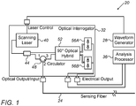
- Fig. 1 is a block diagram that schematically illustrates a fiber-optic reflectometry system 20 that uses I/Q detection, in accordance with an embodiment of the present invention.
- System 20 transmits an optical signal through an optical fiber 24, referred to as a sensing fiber, and analyzes the optical signal reflected from the fiber.
- system 20 detects backscattering from various reflectors at various points along fiber 24, and estimates the locations along the fiber at which such backscattering occur.
- Backscattering may be caused by permanent or transient mechanical faults or deformations in the fiber, or by any other suitable phenomenon or event that affects the fiber's optical properties at certain points. Detection and analysis of backscattering may serve as a basis for a wide variety of sensing applications, as will be elaborated below.
- system 20 comprises a waveform generator 28, an optical interrogation unit 32, and an analysis processor 36.
- Optical interrogation unit comprises a scanning laser 40, an optical splitter 44, a circulator 48, a 90° optical hybrid 52, and a pair of balanced optical detectors 56A and 56B (also referred to as optical receivers).
- Hybrid 52 may also be referred to as an I/Q or quadrature hybrid, mixer, demodulator or downconverter.
- Waveform generator 28 generates a time-varying waveform that modulates the optical frequency (the wavelength) of laser 40.
- laser 40 generates an optical signal whose instantaneous wavelength varies as a function of time.
- waveform generator 28 generates signals having a saw-tooth waveform, which cause laser 40 to produce a periodically chirped signal, i.e., a periodic optical signal whose instantaneous wavelength shifts linearly over time. In each period the frequency is swept over a desired frequency range with some predefined sweep rate.
- chirp signal refers to any signal whose instantaneous wavelength varies as a function of time.
- the wavelength may vary in accordance with any suitable function of time, e.g., a linear, polynomial, logarithmic, stepwise, pseudo-random or other function.
- laser 40 under the control of waveform generator 28 may produce waveforms of any other suitable scanning signal, e.g., an optical signal whose instantaneous wavelength is a sinusoidal, triangular or other suitable function of time.
- the optical signal produced by laser 40 is split using splitter 44 into an interrogation signal and a reference signal.
- the interrogating signal is launched into sensing fiber 24, and a backscattering signal is received from the fiber in response.
- the received backscattering signal is mixed with the reference signal to produce a beat signal that is in turn analyzed.
- the interrogating signal is transmitted via circulator 48 (via ports 1 ⁇ 2 of the circulator) into fiber 24.
- the reference signal (a reference replica of the interrogation signal) is applied to the Local Oscillator (LO) port of hybrid 52.
- the interrogation signal is reflected (e.g., backscattered) from various points along fiber 24. The superposition of these reflections, which returns from fiber 24 to interrogation unit 32, is an optical signal referred to herein as the backscattered signal.
- the backscattered signal passes through circulator 48 (via ports 2 ⁇ 3 of the circulator) and is applied to the signal port of hybrid 52.
- Hybrid 52 has two pairs of output fibers that are connected respectively to balanced optical detectors 56A and 56B.
- Detectors 56A and 56B produce respective electrical signals that represent the In-phase (I) and Quadrature (Q) components of the beat signal (the backscattered signal after it has been down-converted by mixing with the reference signal).
- detectors 56A and 56B produce a complex signal representation of the light backscattered in fiber 24.
- the pair of electrical signals (i.e., the complex beat signal) produced by detectors 56A and 56B is provided to analysis processor 36.
- Processor 36 digitizes the complex beat signal and analyzes it in the frequency domain, so as to detect and localize the points along fiber 24 at which backscattering occurs.
- processor 36 transforms the beat signal into the frequency domain, e.g., by applying a Fourier transform, so as to produce a frequency-domain backscattering profile of the fiber.
- each beat frequency (and thus each frequency bin of the Fourier transform) is mapped to a respective location along the fiber.
- system 20 shown in Fig. 1 is an example configuration, which is chosen purely for the sake of conceptual clarity. In alternative embodiments, any other suitable system configuration can be used.
- waveform generator 28 and laser 40 are referred to jointly as an optical source.
- Hybrid 52 and detectors 56A and 56B are referred to jointly as a beat detection module.
- system 20 may be implemented using any other suitable configuration of the optical source and/or beat detection module.
- fiber 24 comprises a Corning SMF-28 fiber
- laser 40 comprises a laser by Koheras Adjustik of NKT Photonics
- splitter 44 comprises a TW1550R5A2 device provided by Thorlabs
- circulator 48 comprises a 6015-3-APC device provided by Thorlabs
- hybrid 52 comprises a COH24-X device provided by Kylia
- detectors 56A and 56B comprise PDB470C-AC devices provided by Thorlabs.
- any other suitable components can be used.
- Some system elements may be implemented using off-the-shelf or modified test equipment.
- Some system elements, e.g., analysis processor 36 may be implemented using hardware, e.g., using one or more Application-Specific Integrated Circuits (ASICs) or Field-Programmable Gate Arrays (FPGAs), using software, or using a combination of hardware and software elements.
- ASICs Application-Specific Integrated Circuits
- FPGAs Field-Programmable Gate Arrays
- processor 36 may be implemented using one or more general-purpose processors, which are programmed in software to carry out the functions described herein.
- the software may be downloaded to the processors in electronic form, over a network, for example, or it may, alternatively or additionally, be provided and/or stored on non-transitory tangible media, such as magnetic, optical, or electronic memory.
- the update rate i.e., the rate with which the backscattering profile is estimated
- the scan repetition rate and denoted f scan the rate at which the interrogation cycles are transmitted
- L the length of the sensing fiber
- f scan L v / 2.
- system 20 detects the beat signal (the backscattered optical signal after mixing with the reference optical signal) using I/Q detection rather than using real-signal detection.
- the I/Q detection scheme provides a superior trade-off of f scan , L and the achievable spatial resolution, in comparison with real-signal detection. This performance benefit is demonstrated in Figs. 2A and 2B below.
- Figs. 2A and 2B are graphs showing instantaneous signal frequencies as a function of time for real-signal detection and for I/Q detection, respectively.
- Fig. 2B illustrates the principle of operation of system 20, in accordance with an embodiment of the present invention.
- Fig. 2A serves as a baseline for comparison.
- the horizontal axis represents time ( t ), which is also proportional to the longitudinal coordinate z along the fiber.
- the vertical axis represents the instantaneous signal frequency ( f ).
- FIG. 2A illustrates a scenario of real-signal detection.
- the processing window is the time interval in the detected beat signal, over which processor 36 estimates the backscattering profile.
- the backscattering profile is typically estimated by calculating a Fourier transform of the beat signal between the backscattered signal and the reference signal.
- a beat frequency that is generated when the instantaneous frequency of the backscattered signal is lower than that of the reference signal is referred to herein as a positive beat frequency.
- a beat frequency that is generated when the instantaneous frequency of the backscattered signal is higher than that of the reference signal is referred to herein as a negative beat frequency.
- f scan L v /4 is the highest performance (longest fiber, fastest scanning) achievable with the real-signal detection scheme. If all other parameters are fixed, any increase in the fiber length L would cause negative beat frequencies to be present in at least part of processing window 72. Since real-signal detection is unable to distinguish between positive and negative beat frequencies, negative beat frequencies in the processing window of Fig. 2A are regarded as aliasing, and distort the calculation of the backscattering profile.
- system 20 is able to generate and analyze the backscattering profile while v /4 ⁇ f scan L ⁇ v / 2.
- sensing fiber 24 can be modeled as a distributed reflector whose reflectivity is denoted R ( z ), wherein z denotes the longitudinal coordinate along the fiber.
- a line 80 shows the instantaneous frequency of the reference signal.
- Lines 84 and 88 show the instantaneous frequency of the backscattering signal.
- two processing windows 92 and 96 are defined in the detected beat signal, each of size T / 2.
- the first processing window (window 92, T / 2 ⁇ t ⁇ T ) corresponds to the half of fiber 24 closer to system 20 (0 ⁇ z ⁇ L / 2). Across this window, the beat frequencies are guaranteed to be positive.
- the second processing window (window 96, 0 ⁇ t ⁇ T / 2 ) corresponds to the half of fiber 24 that is further away from system 20 (L / 2 ⁇ z ⁇ L ) . Across this window, the beat frequencies are guaranteed to be negative.
- processor 36 calculates the backscattering profile for the near half of fiber 24 by calculating a Fourier transform of the complex backscattering signal V(t) over the first processing window (window 92, T / 2 ⁇ t ⁇ T ), and retaining only the positive-frequency components of the resulting transform.
- processor 36 may calculate the backscattering profile for the distant half of fiber 24 by calculating a Fourier transform of the complex backscattering signal V(t) over the second processing window (window 96, 0 ⁇ t ⁇ T / 2 ), and retaining only the negative-frequency components of the resulting transform.
- processor 36 can divide the detected complex-valued beat signal into one or more first processing windows (in which the beat frequencies are guaranteed to be positive) and one or more second processing windows (in which the beat frequencies are guaranteed to be negative).
- system 20 is able to support twice the fiber length for the same scan repetition rate, or double the scan repetition rate for the same fiber length, without degrading spatial resolution.
- Fig. 3 is a flow chart that schematically illustrates a method for fiber-optic reflectometry using I/Q detection, in accordance with an embodiment of the present invention.
- the method begins with waveform generator 28 modulating laser 40 with a chirped waveform, at a modulation step 100.
- laser 40 generates an interrogation optical signal - A train of interrogating cycles whose instantaneous wavelength varies linearly as a function of time.
- system 20 transmits the interrogation optical signal into sensing fiber 24.
- the reference optical signal is applied to the LO port of hybrid 52, at a reference input step 108.
- the backscattering optical signal is applied to the signal port of hybrid 52, at a backscattering input step 112.
- Detectors 56A and 56B detect the I and Q outputs of hybrid 52, respectively, at an I/Q detection step 116. In other words, detectors 56A and 56B output the respective I and Q components of the complex beat signal between the interrogation signal and the reference signal.
- processor 36 analyzes the complex beat signal in the frequency domain, as explained above, so as to identify reflections occurring in fiber 24.
- the analysis may involve, for example, determining the presence, intensity and z coordinates of reflections in fiber 24.
- systems such as system 20 of Fig. 1 can be used in a wide variety of applications that involve detecting various kinds of events that affect an optical-fiber.
- system 20 is used in dynamic sensing applications that benefit from fast update rate.
- system 20 is used for monitoring optical fibers in an optical communication network, for example in order to detect and locate faults in the fibers.
- the sensed events are typically faults in the optical fiber that impact the communication performance of the network.
- sensing fiber 24 is installed as part of a perimeter defense system for protecting a certain area or structure.
- the sensed events typically relate to illegitimate entry, i.e., illegitimate breach of the perimeter defense system.
- sensing fiber 24 is installed in some utility infrastructure element, in order to detect fatigue-related faults or other faults in the infrastructure.
- the fiber may be installed, for example, in an oil or water pipeline, in a railway line or in a road or bridge.
- the sensed events are typically related to faults in the infrastructure element.
Description
- The present invention relates generally to fiber-optic reflectometry, and particularly to methods and systems for fiber-optic reflectometry using In-phase/Quadrature (I/Q) detection.
- Fiber-optic reflectometry techniques are used for detecting and analyzing impairments and events that affect the optical properties of an optical fiber. Various fiber-optic reflectometry techniques are known in the art. Such techniques are described, for example, by Takada et al., in "New measurement system for fault location in optical waveguide devices based on an interferometric technique," Applied Optics, volume 26, issue 9, 1987, pages 1603-1606; by Bamoski and Jensen, in "Fiber waveguides: a novel technique for investigating attenuation characteristics," Applied Optics, volume 15, issue 9, 1976, pages 2112-2115; and by Bar-Am et al., in "OFDR with double interrogation for dynamic quasi-distributed sensing," Optics Express, volume 22, .
- Additional examples of fiber-optic reflectometry schemes are described by Arbel and Eyal, in "Dynamic optical frequency domain reflectometry," Optics Express, volume 22, issue 8, 2014, pages 8823-8830; and by Zhang and Bao, in "Distributed optical fiber vibration sensor based on spectrum analysis of Polarization-OTDR system," Optics Express, volume 16, issue 14, 2008, pages 10240-10247.
- Some fiber-optic reflectometry techniques are based on Optical Time-Domain Reflectometry (OTDR). OTDR-based schemes are described, for example, by Juarez et al., in "Distributed fiber-optic intrusion sensor system," Journal of Lightwave Technology, volume 23, issue 6, 2005, pages 2081-2087; and by Yuelan et al., in "Distributed vibration sensor based on coherent detection of phase-OTDR," Journal of Lightwave Technology, .
- Other fiber-optic reflectometry techniques are based on Optical Frequency-Domain Reflectometry (OFDR). OFDR-based schemes are described, for example, in the articles by Bar-Am et al. and by Arbel and Eyal, cited above, as well as by Ito et al., in "Long-range coherent OFDR with light source phase noise compensation," Journal of Lightwave Technology, volume 30, issue 8, 2012, pages 1015-1024.
- In the article entitled Dynamic Optical Frequency Domain Reflectometry by Dror Arbel et al published in Optics Express, vol. 22, no. 8, there is disclosed a dynamic optical frequency domain reflectometry system which enables real time, long range, acoustic sensing at high sampling rate. The system is based on a fast scanning laser and coherent detection scheme. Distributed sensing is obtained by probing the Rayleigh backscattered light. The system was tested by interrogation of a 10km communication type single mode fibre and successfully detected localized impulse and sinusoidal excitations.
- An embodiment of the present invention that is described herein provides a system for fiber-optic reflectometry. The system includes an optical source, a beat detection module and a processor. The optical source is configured to generate an optical interrogation signal that is transmitted into an optical fiber. The beat detection module is configured to receive from the optical fiber an optical backscattering signal in response to the optical interrogation signal, and to mix the optical backscattering signal with a reference replica of the optical interrogation signal using In-phase/Quadrature (I/Q) mixing, so as to produce a complex beat signal having In-phase (I) and Quadrature (Q) components. The processor is configured to sense one or more events affecting the optical fiber by analyzing the I and Q components of the complex beat signal. The processor is configured to analyze the complex beat signal by defining in the complex beat signal at least: a first time interval, during which an instantaneous frequency of the optical backscattering signal is guaranteed to be lower than the instantaneous frequency of the reference replica; and a second time interval, during which the instantaneous frequency of the optical backscattering signal is guaranteed to be higher than the instantaneous frequency of the reference replica.
- In an embodiment, the optical interrogation signal includes a periodic chirp signal. In a disclosed embodiment, the beat detection module includes a 90° optical hybrid configured to perform the I/Q mixing. In an example embodiment, the beat detection module includes a pair of optical detectors that are configured to detect the I and Q components of the complex beat signal.
- In an example embodiment, the processor is configured to calculate a backscattering profile of the optical fiber by: calculating a first complex frequency-domain transform of the complex beat signal in the first time interval, and retaining only a positive-frequency part of the first complex frequency-domain transform; and calculating a second complex frequency-domain transform of the complex beat signal in the second time interval, and retaining only a negative-frequency part of the second complex frequency-domain transform. In an embodiment, the processor is configured to sense the events in a first part of the optical fiber based on the first complex frequency-domain transform, and to sense the events in a second part of the optical fiber based on the second complex frequency-domain transform.
- In some embodiments, the optical source is configured to generate the optical interrogation signal with a scan repetition rate fscan, wherein a length of the optical fiber is denoted L, wherein a speed of light in the optical fiber is denoted v, and wherein the processor is configured to sense the event while fscanL ≤ v/2. In an embodiment, the processor is configured to sense the event while v/4 < fscanL ≤ v/2.
- In some embodiments, the optical fiber is part of an optical communication system, and the one or more events include a fault in the optical fiber. In other embodiments, the optical fiber is part of a perimeter defense system, and the one or more events include a breach of the perimeter defense system. In yet other embodiments, the optical fiber is installed in a utility infrastructure, and the one or more events include a fault in the utility infrastructure.
- There is additionally provided, in accordance with an embodiment of the present invention, a method for fiber-optic reflectometry. The method includes transmitting an optical interrogation signal into an optical fiber, receiving from the optical fiber an optical backscattering signal in response to the optical interrogation signal, and mixing the optical backscattering signal with a reference replica of the optical interrogation signal using In-phase/Quadrature (I/Q) mixing, so as to produce a complex beat signal having In-phase (I) and Quadrature (Q) components. One or more events affecting the optical fiber are sensed by analyzing the I and Q components of the complex beat signal.
- There is further provided, in accordance with an embodiment of the present invention, a system for fiber-optic reflectometry. The system includes an optical source, a beat detection module and a processor. The optical source is configured to generate an optical interrogation signal that is transmitted into an optical fiber. The beat detection module is configured to receive from the optical fiber an optical backscattering signal in response to the optical interrogation signal, to mix the optical backscattering signal with a reference replica of the optical interrogation signal so as to produce a beat signal, and to distinguish in the beat signal between (i) a first component in which an instantaneous frequency of the optical backscattering signal is lower than the instantaneous frequency of the reference replica and (ii) a second component in which the instantaneous frequency of the optical backscattering signal is higher than the instantaneous frequency of the reference replica. The processor is configured to sense one or more events affecting the optical fiber by analyzing the first and second components of the beat signal.
- There is also provided, in accordance with an embodiment of the present invention, a method for fiber-optic reflectometry. The method includes transmitting an optical interrogation signal into an optical fiber, receiving from the optical fiber an optical backscattering signal in response to the optical interrogation signal, and mixing the optical backscattering signal with a reference replica of the optical interrogation signal, so as to produce a beat signal. A distinction is made in the beat signal between (i) a first component in which an instantaneous frequency of the optical backscattering signal is lower than the instantaneous frequency of the reference replica and (ii) a second component in which the instantaneous frequency of the optical backscattering signal is higher than the instantaneous frequency of the reference replica. One or more events affecting the optical fiber are sensed by analyzing the first and second components of the beat signal.
- The present invention will be more fully understood from the following detailed description of the embodiments thereof, taken together with the drawings in which:
-
-
Fig. 1 is a block diagram that schematically illustrates a fiber-optic reflectometry system that uses I/Q detection, in accordance with an embodiment of the present invention; -
Fig. 2A is a graph showing instantaneous signal frequencies as a function of time in a fiber-optic reflectometry system that uses real-signal detection; -
Fig. 2B is a graph showing instantaneous signal frequencies as a function of time in a fiber-optic reflectometry system that uses I/Q detection, in accordance with an embodiment of the present invention; and -
Fig. 3 is a flow chart that schematically illustrates a method for fiber-optic reflectometry using I/Q detection, in accordance with an embodiment of the present invention. - Embodiments of the present invention that are described herein provide improved methods and systems for fiber-optic reflectometry. The disclosed techniques can be used for implementing various types of sensors for use in a wide variety of applications. Example applications include optical network monitoring, perimeter defense, as well as monitoring of infrastructure such as pipelines, railways and roads, to name just a few.
- In the disclosed embodiments, an Optical Frequency-Domain Reflectometry (OFDR) system generates an optical interrogation signal into an optical fiber of length L. The interrogation signal comprises a periodic optical signal whose instantaneous wavelength varies as a function of time and has a repetition rate fscan. A backscattering optical signal is received from the fiber in response to the interrogation signal. The system optically mixes the backscattering signal with a reference replica of the interrogation signal to produce a beat signal. The system detects and digitizes the beat signal, and transforms it into the frequency domain, so as to produce a frequency-domain backscattering profile of the fiber. The system then analyzes the backscattering profile depending of the application.
- As will be shown below, if the optical mixing and subsequent detection of the beat signal are performed using a real-signal receiver scheme, the fiber length and the scan repetition rate must satisfy fscanL ≤ v/4, wherein v denotes the speed of light in the fiber. Thus, the longest fiber or fastest scan repetition rate are achieved when fscanL = v/4.
- In contrast, in embodiments of the present invention the optical mixing and subsequent detection are performed using a complex-signal, In-phase/Quadrature (I/Q) receiver scheme. In some embodiments, the system mixes the backscattering signal with the reference signal using a 90° optical hybrid and detects the beat signal using a pair of balanced optical detectors in quadrature.
- As will be explained in detail below, the I/Q detection scheme enables the system to distinguish between positive and negative beat frequencies. As a result, the upper bound on the product fscanL is doubled relative to real-signal detection. In other words, when using the disclosed I/Q scheme, the longest fiber or fastest scan repetition rate are achieved when fscanL = v/2.
- In summary, the methods and systems described herein use I/Q optical mixing and detection to provide a considerable increase in the achievable scan repetition rate and fiber length, without degradation in spatial resolution or other performance. The disclosed techniques are particularly beneficial in dynamic sensing applications i.e., applications that require sensing with a high update rate.
-
Fig. 1 is a block diagram that schematically illustrates a fiber-optic reflectometry system 20 that uses I/Q detection, in accordance with an embodiment of the present invention.System 20 transmits an optical signal through anoptical fiber 24, referred to as a sensing fiber, and analyzes the optical signal reflected from the fiber. - In particular,
system 20 detects backscattering from various reflectors at various points alongfiber 24, and estimates the locations along the fiber at which such backscattering occur. Backscattering may be caused by permanent or transient mechanical faults or deformations in the fiber, or by any other suitable phenomenon or event that affects the fiber's optical properties at certain points. Detection and analysis of backscattering may serve as a basis for a wide variety of sensing applications, as will be elaborated below. - In the present example,
system 20 comprises awaveform generator 28, anoptical interrogation unit 32, and ananalysis processor 36. Optical interrogation unit comprises ascanning laser 40, anoptical splitter 44, acirculator 48, a 90°optical hybrid 52, and a pair of balancedoptical detectors Hybrid 52 may also be referred to as an I/Q or quadrature hybrid, mixer, demodulator or downconverter. -
Waveform generator 28 generates a time-varying waveform that modulates the optical frequency (the wavelength) oflaser 40. As a result,laser 40 generates an optical signal whose instantaneous wavelength varies as a function of time. In the presentexample waveform generator 28 generates signals having a saw-tooth waveform, which causelaser 40 to produce a periodically chirped signal, i.e., a periodic optical signal whose instantaneous wavelength shifts linearly over time. In each period the frequency is swept over a desired frequency range with some predefined sweep rate. - Although the description that follows refers mainly to a linear-chirp optical signal, for the sake of clarity, the disclosed techniques are in no way limited to this sort of signal. In the context of the present patent application and in the claims, the term "chirp signal" refers to any signal whose instantaneous wavelength varies as a function of time. The wavelength may vary in accordance with any suitable function of time, e.g., a linear, polynomial, logarithmic, stepwise, pseudo-random or other function.
- Alternatively,
laser 40 under the control ofwaveform generator 28 may produce waveforms of any other suitable scanning signal, e.g., an optical signal whose instantaneous wavelength is a sinusoidal, triangular or other suitable function of time. - The optical signal produced by
laser 40 is split usingsplitter 44 into an interrogation signal and a reference signal. The interrogating signal is launched intosensing fiber 24, and a backscattering signal is received from the fiber in response. The received backscattering signal is mixed with the reference signal to produce a beat signal that is in turn analyzed. - In the example of
Fig. 1 , the interrogating signal is transmitted via circulator 48 (viaports 1⇒2 of the circulator) intofiber 24. The reference signal (a reference replica of the interrogation signal) is applied to the Local Oscillator (LO) port ofhybrid 52. The interrogation signal is reflected (e.g., backscattered) from various points alongfiber 24. The superposition of these reflections, which returns fromfiber 24 tointerrogation unit 32, is an optical signal referred to herein as the backscattered signal. The backscattered signal passes through circulator 48 (viaports 2⇒3 of the circulator) and is applied to the signal port ofhybrid 52. -
Hybrid 52 has two pairs of output fibers that are connected respectively to balancedoptical detectors Detectors detectors fiber 24. - The pair of electrical signals (i.e., the complex beat signal) produced by
detectors analysis processor 36.Processor 36 digitizes the complex beat signal and analyzes it in the frequency domain, so as to detect and localize the points alongfiber 24 at which backscattering occurs. Typically,processor 36 transforms the beat signal into the frequency domain, e.g., by applying a Fourier transform, so as to produce a frequency-domain backscattering profile of the fiber. Generally speaking, each beat frequency (and thus each frequency bin of the Fourier transform) is mapped to a respective location along the fiber. The functions ofprocessor 36 are addressed in greater detail further below. - The configuration of
system 20 shown inFig. 1 is an example configuration, which is chosen purely for the sake of conceptual clarity. In alternative embodiments, any other suitable system configuration can be used. In the present context,waveform generator 28 andlaser 40 are referred to jointly as an optical source.Hybrid 52 anddetectors system 20 may be implemented using any other suitable configuration of the optical source and/or beat detection module. - The different elements of
system 20 may be implemented using various suitable optical and/or electronic hardware components, integrated or discrete. In one example embodiment,fiber 24 comprises a Corning SMF-28 fiber,laser 40 comprises a laser by Koheras Adjustik of NKT Photonics,splitter 44 comprises a TW1550R5A2 device provided by Thorlabs, circulator 48 comprises a 6015-3-APC device provided by Thorlabs,hybrid 52 comprises a COH24-X device provided by Kylia,detectors - Some system elements, e.g.,
waveform generator 28, may be implemented using off-the-shelf or modified test equipment. Some system elements, e.g.,analysis processor 36, may be implemented using hardware, e.g., using one or more Application-Specific Integrated Circuits (ASICs) or Field-Programmable Gate Arrays (FPGAs), using software, or using a combination of hardware and software elements. - In some embodiments,
processor 36 may be implemented using one or more general-purpose processors, which are programmed in software to carry out the functions described herein. The software may be downloaded to the processors in electronic form, over a network, for example, or it may, alternatively or additionally, be provided and/or stored on non-transitory tangible media, such as magnetic, optical, or electronic memory. - Consider a dynamic fiber-optic reflectometry application, in which the fiber deformations or faults that should be detected vary over time. In such applications, the update rate, i.e., the rate with which the backscattering profile is estimated, is often a major design consideration. A trade-off typically exists between the rate at which the interrogation cycles are transmitted (referred to as the scan repetition rate and denoted fscan ) and the length of the sensing fiber (denoted L). This trade-off is due to the constraint that, following an interrogation cycle, the resulting backscattered signal should fully exit the fiber before the next interrogation cycle begins.
- In order to meet this constraint, the scan repetition rate and the fiber length should satisfy fscanL ≤ v/2 = 108 m/s, wherein v denotes the speed of light in the fiber. Thus, with all other parameters fixed, the longest fiber and/or the fastest scan repetition rate are achieved when fscanL = v/2.
- As explained above,
system 20 detects the beat signal (the backscattered optical signal after mixing with the reference optical signal) using I/Q detection rather than using real-signal detection. The I/Q detection scheme provides a superior trade-off of fscan, L and the achievable spatial resolution, in comparison with real-signal detection. This performance benefit is demonstrated inFigs. 2A and 2B below. -
Figs. 2A and 2B are graphs showing instantaneous signal frequencies as a function of time for real-signal detection and for I/Q detection, respectively.Fig. 2B illustrates the principle of operation ofsystem 20, in accordance with an embodiment of the present invention.Fig. 2A serves as a baseline for comparison. In both figures, the horizontal axis represents time (t), which is also proportional to the longitudinal coordinate z along the fiber. The vertical axis represents the instantaneous signal frequency (f). - Reference is now made to
Fig. 2A , which illustrates a scenario of real-signal detection. Aline 60 plots the instantaneous frequency of the reference signal, andlines - A "processing window" 72 is defined as the time interval between t = 2L/v and t = T. The processing window is the time interval in the detected beat signal, over which
processor 36 estimates the backscattering profile. As noted above, the backscattering profile is typically estimated by calculating a Fourier transform of the beat signal between the backscattered signal and the reference signal. - In the present example, parameters were chosen such that fscanL = v/4. This choice guarantees that the instantaneous frequency of the backscattered signal (line 64) is guaranteed to be lower than the instantaneous frequency of the reference signal (line 60) across the
entire processing window 72. - Without loss of generality, a beat frequency that is generated when the instantaneous frequency of the backscattered signal is lower than that of the reference signal is referred to herein as a positive beat frequency. Similarly, a beat frequency that is generated when the instantaneous frequency of the backscattered signal is higher than that of the reference signal is referred to herein as a negative beat frequency.
- As can be seen in
Fig. 2A , fscanL = v/4 is the highest performance (longest fiber, fastest scanning) achievable with the real-signal detection scheme. If all other parameters are fixed, any increase in the fiber length L would cause negative beat frequencies to be present in at least part ofprocessing window 72. Since real-signal detection is unable to distinguish between positive and negative beat frequencies, negative beat frequencies in the processing window ofFig. 2A are regarded as aliasing, and distort the calculation of the backscattering profile. - Thus, in the real-signal detection scheme of
Fig. 2A , in order to increase the fiber length L it is necessary to either reduce the scan repetition rate fscan or to decrease the size ofprocessing window 72. Both solutions, however, would degrade performance. Reducing fscan degrades the dynamic performance of the system, e.g., the ability to detect temporal changes in the backscattering profile. Reducing the size of the processing window degrades the achievable spatial resolution. - As will be demonstrated using
Fig. 2B , the I/Q detection scheme ofsystem 20 enables fscanL to reach the theoretical limit fscanL = v/2, without introducing aliasing or degrading spatial resolution. In particular, unlike real-signal-based schemes,system 20 is able to generate and analyze the backscattering profile while v/4 < fscanL ≤ v/2. - In the detection scheme of
system 20, sensingfiber 24 can be modeled as a distributed reflector whose reflectivity is denoted R(z), wherein z denotes the longitudinal coordinate along the fiber. The in-phase and quadrature electrical signals at the output ofdetectors 56A and 56D can be written as:

detectors - The beat frequency during one scan period can be written as:


fiber 24 as a function of z. - Reference is now made to
Fig. 2B , which illustrates the signals insystem 20 when fscanL is set to the theoretical optimum value fscanL = v/2. Aline 80 shows the instantaneous frequency of the reference signal.Lines - In the case of I/Q detection, two processing
windows window 92, T/2 ≤ t < T) corresponds to the half offiber 24 closer to system 20 (0 ≤ z < L/2). Across this window, the beat frequencies are guaranteed to be positive. The second processing window (window 96, 0 ≤ t < T/2) corresponds to the half offiber 24 that is further away from system 20 (L/2 ≤ z < L). Across this window, the beat frequencies are guaranteed to be negative. - In some embodiments,
processor 36 calculates the backscattering profile for the near half offiber 24 by calculating a Fourier transform of the complex backscattering signal V(t) over the first processing window (window 92, T/2 ≤ t < T), and retaining only the positive-frequency components of the resulting transform. - Similarly,
processor 36 may calculate the backscattering profile for the distant half offiber 24 by calculating a Fourier transform of the complex backscattering signal V(t) over the second processing window (window 96, 0 ≤ t < T/2), and retaining only the negative-frequency components of the resulting transform. - The description of
Fig. 2B above refers to the optimum case in which fscanL = v/2. The disclosed techniques, however, can also be used in other scenarios and other choices of parameters that meet the condition fscanL ≤ v/2. As long as this condition is met,processor 36 can divide the detected complex-valued beat signal into one or more first processing windows (in which the beat frequencies are guaranteed to be positive) and one or more second processing windows (in which the beat frequencies are guaranteed to be negative). - In summary, the above comparison between real-signal detection (
Fig. 2A ) and I/Q detection (Fig. 2B ) shows that I/Q detection is able to perform OFDR-based optical-fiber reflectometry while increasing the product fscanL by up to a factor of two. For example, relative to a comparable system that uses real-signal detection,system 20 is able to support twice the fiber length for the same scan repetition rate, or double the scan repetition rate for the same fiber length, without degrading spatial resolution. - The inventors have verified the performance of the disclosed technique using a computer simulation. Description of the simulation setup and example simulation results are provided in
U.S. Provisional Patent Application 62/080,329 -
Fig. 3 is a flow chart that schematically illustrates a method for fiber-optic reflectometry using I/Q detection, in accordance with an embodiment of the present invention. The method begins withwaveform generator 28 modulatinglaser 40 with a chirped waveform, at amodulation step 100. As a result,laser 40 generates an interrogation optical signal - A train of interrogating cycles whose instantaneous wavelength varies linearly as a function of time. At atransmission step 104,system 20 transmits the interrogation optical signal intosensing fiber 24. - The reference optical signal is applied to the LO port of
hybrid 52, at areference input step 108. The backscattering optical signal is applied to the signal port ofhybrid 52, at abackscattering input step 112.Detectors hybrid 52, respectively, at an I/Q detection step 116. In other words,detectors - At an
analysis step 120,processor 36 analyzes the complex beat signal in the frequency domain, as explained above, so as to identify reflections occurring infiber 24. The analysis may involve, for example, determining the presence, intensity and z coordinates of reflections infiber 24. - In various embodiments, systems such as
system 20 ofFig. 1 can be used in a wide variety of applications that involve detecting various kinds of events that affect an optical-fiber. Typically, although not necessarily,system 20 is used in dynamic sensing applications that benefit from fast update rate. - In some embodiments,
system 20 is used for monitoring optical fibers in an optical communication network, for example in order to detect and locate faults in the fibers. In this application, the sensed events are typically faults in the optical fiber that impact the communication performance of the network. - In other embodiments, sensing
fiber 24 is installed as part of a perimeter defense system for protecting a certain area or structure. In such applications, the sensed events typically relate to illegitimate entry, i.e., illegitimate breach of the perimeter defense system. - In other embodiments, sensing
fiber 24 is installed in some utility infrastructure element, in order to detect fatigue-related faults or other faults in the infrastructure. The fiber may be installed, for example, in an oil or water pipeline, in a railway line or in a road or bridge. In this sort of application, the sensed events are typically related to faults in the infrastructure element. - The applications listed above are depicted purely by way of example. In alternative embodiments, the disclosed techniques can be used as part of any other suitable system and for any other suitable application.
- It will thus be appreciated that the embodiments described above are cited by way of example, and that the present invention is not limited to what has been particularly shown and described hereinabove. Rather, the scope of the present invention includes both combinations and sub-combinations of the various features described hereinabove, as well as variations and modifications thereof which would occur to persons skilled in the art upon reading the foregoing description and which are not disclosed in the prior art. Documents incorporated by reference in the present patent application are to be considered an integral part of the application except that to the extent any terms are defined in these incorporated documents in a manner that conflicts with the definitions made explicitly or implicitly in the present specification, only the definitions in the present specification should be considered.
Claims (13)
- A system (20) for fiber-optic reflectometry, the system comprising:an optical source (40), which is configured to generate an optical interrogation signal that is transmitted into an optical fiber (24);a beat detection module, which is configured to receive from the optical fiber (24) an optical backscattering signal in response to the optical interrogation signal, and to mix the optical backscattering signal with a reference replica of the optical interrogation signal using In-phase/Quadrature (I/Q) mixing, so as to produce a complex beat signal having In-phase (I) and Quadrature (Q) components; anda processor (36), which is configured to sense one or more events affecting the optical fiber by analyzing the I and Q components of the complex beat signal, characterized in thatthe processor is configured to analyze the complex beat signal by defining in the complex beat signal at least:a first time interval, during which an instantaneous frequency of the optical backscattering signal is guaranteed to be lower than the instantaneous frequency of the reference replica; anda second time interval, during which the instantaneous frequency of the optical backscattering signal is guaranteed to be higher than the instantaneous frequency of the reference replica.
- The system according to claim 1, wherein the optical interrogation signal comprises a periodic chirp signal.
- The system according to claim 1, wherein the beat detection module comprises a 90° optical hybrid configured to perform the I/Q mixing.
- The system according to claim 1, wherein the beat detection module comprises a pair of optical detectors (56A;56B) that are configured to detect the I and Q components of the complex beat signal.
- The system according to claim 1, wherein the processor is configured to calculate a backscattering profile of the optical fiber by:calculating a first complex frequency-domain transform of the complex beat signal in the first time interval, and retaining only a positive-frequency part of the first complex frequency-domain transform; andcalculating a second complex frequency-domain transform of the complex beat signal in the second time interval, and retaining only a negative-frequency part of the second complex frequency-domain transform.
- The system according to claim 5, wherein the processor is configured to sense the events in a first part of the optical fiber based on the first complex frequency-domain transform, and to sense the events in a second part of the optical fiber based on the second complex frequency-domain transform.
- The system according to any of claims 1-4, wherein the optical source is configured to generate the optical interrogation signal with a scan repetition rate fscan, wherein a length of the optical fiber is denoted L, wherein a speed of light in the optical fiber is denoted v, and wherein the processor is configured to sense the event while fscanL ≤ v/2.
- The system according to claim 7, wherein the processor is configured to sense the event while v/4 < fscanL ≤ v/2.
- The system according to any of claims 1-4, wherein the optical fiber is part of an optical communication system, and wherein the one or more events comprise a fault in the optical fiber.
- The system according to any of claims 1-4, wherein the optical fiber is part of a perimeter defense system, and wherein the one or more events comprise a breach of the perimeter defense system.
- The system according to any of claims 1-4, wherein the optical fiber is installed in a utility infrastructure, and wherein the one or more events comprise a fault in the utility infrastructure.
- A method for fiber-optic reflectometry, the method comprising:transmitting (104) an optical interrogation signal into an optical fiber (24);receiving from the optical fiber an optical backscattering signal in response to the optical interrogation signal;mixing the optical backscattering signal with a reference replica of the optical interrogation signal using In-phase/Quadrature (I/Q) mixing, so as to produce a complex beat signal having In-phase (I) and Quadrature (Q) components; andsensing one or more events affecting the optical fiber (24) by analyzing the I and Q components of the complex beat signal, characterized in thatanalyzing the complex beat signal comprises defining in the complex beat signal at least:a first time interval, during which an instantaneous frequency of the optical backscattering signal is guaranteed to be lower than the instantaneous frequency of the reference replica; anda second time interval, during which the instantaneous frequency of the optical backscattering signal is guaranteed to be higher than the instantaneous frequency of the reference replica.
- The method according to claim 12, wherein the optical interrogation signal comprises a periodic chirped signal.
Applications Claiming Priority (3)
| Application Number | Priority Date | Filing Date | Title |
|---|---|---|---|
| US201462080329P | 2014-11-16 | 2014-11-16 | |
| IL24229815 | 2015-10-27 | ||
| PCT/IB2015/058819 WO2016075672A1 (en) | 2014-11-16 | 2015-11-15 | Spectrally efficient optical frequency-domain reflectometry using i/q detection |
Publications (3)
| Publication Number | Publication Date |
|---|---|
| EP3219027A1 EP3219027A1 (en) | 2017-09-20 |
| EP3219027A4 EP3219027A4 (en) | 2018-08-08 |
| EP3219027B1 true EP3219027B1 (en) | 2019-10-16 |
Family
ID=55953814
Family Applications (1)
| Application Number | Title | Priority Date | Filing Date |
|---|---|---|---|
| EP15859673.4A Active EP3219027B1 (en) | 2014-11-16 | 2015-11-15 | Spectrally efficient optical frequency-domain reflectometry using i/q detection |
Country Status (3)
| Country | Link |
|---|---|
| US (1) | US10190940B2 (en) |
| EP (1) | EP3219027B1 (en) |
| WO (1) | WO2016075672A1 (en) |
Families Citing this family (6)
| Publication number | Priority date | Publication date | Assignee | Title |
|---|---|---|---|---|
| IL243731B (en) | 2016-01-23 | 2021-01-31 | Dsit Solutions Ltd | Non-linear frequency scan optical frequency-domain reflectometry |
| US10670389B2 (en) * | 2017-02-23 | 2020-06-02 | General Photonics Corporation | Sensitive optical fiber shape sensing based on shape-related optical polarization evolution |
| JP6887901B2 (en) * | 2017-07-11 | 2021-06-16 | 学校法人明治大学 | Measuring device and measuring method |
| DE102018124435A1 (en) * | 2018-10-03 | 2020-04-09 | Nkt Photonics Gmbh | Distributed measuring device |
| JP7331373B2 (en) * | 2019-02-12 | 2023-08-23 | 日本電信電話株式会社 | Optical frequency reflection measurement device and its measurement method |
| CN114111860B (en) * | 2021-12-03 | 2022-08-30 | 北京科技大学 | Distributed phi-OTDR sensing method and system based on multi-frequency pulse coding |
Family Cites Families (7)
| Publication number | Priority date | Publication date | Assignee | Title |
|---|---|---|---|---|
| US5062703A (en) * | 1988-01-21 | 1991-11-05 | Hewlett-Packard Company | Method and apparatus for measuring the length of, or distances to discontinuities in, an optical transmission medium |
| DE4325758A1 (en) * | 1993-02-23 | 1995-02-02 | Jenoptik Jena Gmbh | Phase-modulated interferometer III |
| JP3282135B2 (en) * | 1993-06-17 | 2002-05-13 | 日本電信電話株式会社 | Optical frequency domain reflectometer |
| JP5148420B2 (en) * | 2008-09-05 | 2013-02-20 | アンリツ株式会社 | Optical fiber testing equipment |
| WO2013003141A2 (en) | 2011-06-28 | 2013-01-03 | Luna Innovations Incorporated | Fiber optic network interrogation tool for combined swept-heterodyne optical spectrum analysis and optical frequency-domain reflectometry |
| US8681322B2 (en) * | 2011-10-12 | 2014-03-25 | Baker Hughes Incorporated | Distance measurement using incoherent optical reflectometry |
| EP2720388A1 (en) | 2012-10-15 | 2014-04-16 | Koninklijke Philips N.V. | An optical frequency domain reflectometry (OFDR) system |
-
2015
- 2015-11-15 US US15/520,417 patent/US10190940B2/en active Active
- 2015-11-15 EP EP15859673.4A patent/EP3219027B1/en active Active
- 2015-11-15 WO PCT/IB2015/058819 patent/WO2016075672A1/en active Application Filing
Non-Patent Citations (1)
| Title |
|---|
| None * |
Also Published As
| Publication number | Publication date |
|---|---|
| US10190940B2 (en) | 2019-01-29 |
| US20170307475A1 (en) | 2017-10-26 |
| EP3219027A1 (en) | 2017-09-20 |
| WO2016075672A1 (en) | 2016-05-19 |
| EP3219027A4 (en) | 2018-08-08 |
Similar Documents
| Publication | Publication Date | Title |
|---|---|---|
| EP3219027B1 (en) | Spectrally efficient optical frequency-domain reflectometry using i/q detection | |
| JP7293321B2 (en) | Distributed optical sensing system and method | |
| EP1817561B1 (en) | Detecting a disturbance in the propagation of light in an optical waveguide | |
| US10330594B2 (en) | Non-linear frequency scan optical frequency-domain reflectometry having a processor to estimate a backscattering profile of an optical fiber by applying a predefined function to a beat signal | |
| JP6342019B2 (en) | Distributed optical fiber acoustic wave detector | |
| CN102739311B (en) | Fiber failure positioner and localization method thereof based on chaos visible laser | |
| US20200355547A1 (en) | Event Positioning Method, Device and Application in Distributed Fiber Vibration Monitoring System | |
| Mompó et al. | Distributed dynamic strain sensing via perfect periodic coherent codes and a polarization diversity receiver | |
| EP3014222A1 (en) | Improvements in fibre optic distributed sensing | |
| RU2530244C2 (en) | Distributed coherent reflectometric system with phase demodulation (versions) | |
| Liehr | Fibre optic sensing techniques based on incoherent optical frequency domain reflectometry | |
| Iida et al. | Advances in distributed vibration sensing for optical communication fiber state visualization | |
| CN114543973A (en) | Distributed ultrahigh frequency vibration signal measuring method and optical fiber sensor | |
| WO2022136832A1 (en) | Fibre optic sensing | |
| CN104038281A (en) | Long-distance high-resolution optical frequency domain reflection demodulation method of nonlinear phase estimation | |
| CN108489640B (en) | Distributed dynamic stress frequency measurement method based on white light interference | |
| ES2757811T3 (en) | Spectrally efficient optical reflectometry in the frequency domain using I / Q detection | |
| Liehr et al. | Performance of digital incoherent OFDR and prospects for optical fiber sensing applications | |
| Xiang et al. | Distributed sensing network using a chirped ultra-weak fiber Bragg grating array | |
| Wang et al. | Measuring very low frequency with phase-OTDR assisted by an auxiliary interferometer | |
| Shiloh et al. | Fast sinusoidal frequency scan OFDR for long distance distributed acoustic sensing | |
| Fu et al. | Impact of optical front-end imbalance in Φ-OTDR with coherent receiver | |
| Mompó Roselló et al. | Distributed dynamic strain sensing via perfect periodic coherent codes and a polarization diversity receiver | |
| US20220349860A1 (en) | Optical fiber distribution measurement system and signal processing method for optical fiber distribution measurement | |
| Pu et al. | Complex Domain Frequency-shift Demodulation in Phase-sensitive OTDR |
Legal Events
| Date | Code | Title | Description |
|---|---|---|---|
| STAA | Information on the status of an ep patent application or granted ep patent |
Free format text: STATUS: THE INTERNATIONAL PUBLICATION HAS BEEN MADE |
|
| PUAI | Public reference made under article 153(3) epc to a published international application that has entered the european phase |
Free format text: ORIGINAL CODE: 0009012 |
|
| STAA | Information on the status of an ep patent application or granted ep patent |
Free format text: STATUS: REQUEST FOR EXAMINATION WAS MADE |
|
| 17P | Request for examination filed |
Effective date: 20170418 |
|
| AK | Designated contracting states |
Kind code of ref document: A1 Designated state(s): AL AT BE BG CH CY CZ DE DK EE ES FI FR GB GR HR HU IE IS IT LI LT LU LV MC MK MT NL NO PL PT RO RS SE SI SK SM TR |
|
| AX | Request for extension of the european patent |
Extension state: BA ME |
|
| DAV | Request for validation of the european patent (deleted) | ||
| DAX | Request for extension of the european patent (deleted) | ||
| A4 | Supplementary search report drawn up and despatched |
Effective date: 20180706 |
|
| RIC1 | Information provided on ipc code assigned before grant |
Ipc: G01B 9/00 20060101ALI20180702BHEP Ipc: H04B 10/071 20130101AFI20180702BHEP |
|
| GRAP | Despatch of communication of intention to grant a patent |
Free format text: ORIGINAL CODE: EPIDOSNIGR1 |
|
| STAA | Information on the status of an ep patent application or granted ep patent |
Free format text: STATUS: GRANT OF PATENT IS INTENDED |
|
| INTG | Intention to grant announced |
Effective date: 20190520 |
|
| GRAJ | Information related to disapproval of communication of intention to grant by the applicant or resumption of examination proceedings by the epo deleted |
Free format text: ORIGINAL CODE: EPIDOSDIGR1 |
|
| STAA | Information on the status of an ep patent application or granted ep patent |
Free format text: STATUS: REQUEST FOR EXAMINATION WAS MADE |
|
| GRAR | Information related to intention to grant a patent recorded |
Free format text: ORIGINAL CODE: EPIDOSNIGR71 |
|
| GRAS | Grant fee paid |
Free format text: ORIGINAL CODE: EPIDOSNIGR3 |
|
| STAA | Information on the status of an ep patent application or granted ep patent |
Free format text: STATUS: GRANT OF PATENT IS INTENDED |
|
| GRAA | (expected) grant |
Free format text: ORIGINAL CODE: 0009210 |
|
| STAA | Information on the status of an ep patent application or granted ep patent |
Free format text: STATUS: THE PATENT HAS BEEN GRANTED |
|
| INTC | Intention to grant announced (deleted) | ||
| AK | Designated contracting states |
Kind code of ref document: B1 Designated state(s): AL AT BE BG CH CY CZ DE DK EE ES FI FR GB GR HR HU IE IS IT LI LT LU LV MC MK MT NL NO PL PT RO RS SE SI SK SM TR |
|
| INTG | Intention to grant announced |
Effective date: 20190906 |
|
| REG | Reference to a national code |
Ref country code: GB Ref legal event code: FG4D |
|
| REG | Reference to a national code |
Ref country code: CH Ref legal event code: EP |
|
| REG | Reference to a national code |
Ref country code: DE Ref legal event code: R096 Ref document number: 602015040048 Country of ref document: DE |
|
| REG | Reference to a national code |
Ref country code: IE Ref legal event code: FG4D |
|
| REG | Reference to a national code |
Ref country code: AT Ref legal event code: REF Ref document number: 1192324 Country of ref document: AT Kind code of ref document: T Effective date: 20191115 |
|
| REG | Reference to a national code |
Ref country code: NL Ref legal event code: FP |
|
| REG | Reference to a national code |
Ref country code: CH Ref legal event code: NV Representative=s name: NOVAGRAAF INTERNATIONAL SA, CH |
|
| REG | Reference to a national code |
Ref country code: LT Ref legal event code: MG4D |
|
| REG | Reference to a national code |
Ref country code: AT Ref legal event code: MK05 Ref document number: 1192324 Country of ref document: AT Kind code of ref document: T Effective date: 20191016 |
|
| REG | Reference to a national code |
Ref country code: ES Ref legal event code: FG2A Ref document number: 2757811 Country of ref document: ES Kind code of ref document: T3 Effective date: 20200430 |
|
| PG25 | Lapsed in a contracting state [announced via postgrant information from national office to epo] |
Ref country code: AT Free format text: LAPSE BECAUSE OF FAILURE TO SUBMIT A TRANSLATION OF THE DESCRIPTION OR TO PAY THE FEE WITHIN THE PRESCRIBED TIME-LIMIT Effective date: 20191016 Ref country code: SE Free format text: LAPSE BECAUSE OF FAILURE TO SUBMIT A TRANSLATION OF THE DESCRIPTION OR TO PAY THE FEE WITHIN THE PRESCRIBED TIME-LIMIT Effective date: 20191016 Ref country code: LV Free format text: LAPSE BECAUSE OF FAILURE TO SUBMIT A TRANSLATION OF THE DESCRIPTION OR TO PAY THE FEE WITHIN THE PRESCRIBED TIME-LIMIT Effective date: 20191016 Ref country code: PT Free format text: LAPSE BECAUSE OF FAILURE TO SUBMIT A TRANSLATION OF THE DESCRIPTION OR TO PAY THE FEE WITHIN THE PRESCRIBED TIME-LIMIT Effective date: 20200217 Ref country code: FI Free format text: LAPSE BECAUSE OF FAILURE TO SUBMIT A TRANSLATION OF THE DESCRIPTION OR TO PAY THE FEE WITHIN THE PRESCRIBED TIME-LIMIT Effective date: 20191016 Ref country code: BG Free format text: LAPSE BECAUSE OF FAILURE TO SUBMIT A TRANSLATION OF THE DESCRIPTION OR TO PAY THE FEE WITHIN THE PRESCRIBED TIME-LIMIT Effective date: 20200116 Ref country code: PL Free format text: LAPSE BECAUSE OF FAILURE TO SUBMIT A TRANSLATION OF THE DESCRIPTION OR TO PAY THE FEE WITHIN THE PRESCRIBED TIME-LIMIT Effective date: 20191016 Ref country code: NO Free format text: LAPSE BECAUSE OF FAILURE TO SUBMIT A TRANSLATION OF THE DESCRIPTION OR TO PAY THE FEE WITHIN THE PRESCRIBED TIME-LIMIT Effective date: 20200116 Ref country code: GR Free format text: LAPSE BECAUSE OF FAILURE TO SUBMIT A TRANSLATION OF THE DESCRIPTION OR TO PAY THE FEE WITHIN THE PRESCRIBED TIME-LIMIT Effective date: 20200117 Ref country code: LT Free format text: LAPSE BECAUSE OF FAILURE TO SUBMIT A TRANSLATION OF THE DESCRIPTION OR TO PAY THE FEE WITHIN THE PRESCRIBED TIME-LIMIT Effective date: 20191016 |
|
| PG25 | Lapsed in a contracting state [announced via postgrant information from national office to epo] |
Ref country code: HR Free format text: LAPSE BECAUSE OF FAILURE TO SUBMIT A TRANSLATION OF THE DESCRIPTION OR TO PAY THE FEE WITHIN THE PRESCRIBED TIME-LIMIT Effective date: 20191016 Ref country code: IS Free format text: LAPSE BECAUSE OF FAILURE TO SUBMIT A TRANSLATION OF THE DESCRIPTION OR TO PAY THE FEE WITHIN THE PRESCRIBED TIME-LIMIT Effective date: 20200224 Ref country code: RS Free format text: LAPSE BECAUSE OF FAILURE TO SUBMIT A TRANSLATION OF THE DESCRIPTION OR TO PAY THE FEE WITHIN THE PRESCRIBED TIME-LIMIT Effective date: 20191016 |
|
| PG25 | Lapsed in a contracting state [announced via postgrant information from national office to epo] |
Ref country code: AL Free format text: LAPSE BECAUSE OF FAILURE TO SUBMIT A TRANSLATION OF THE DESCRIPTION OR TO PAY THE FEE WITHIN THE PRESCRIBED TIME-LIMIT Effective date: 20191016 |
|
| REG | Reference to a national code |
Ref country code: DE Ref legal event code: R097 Ref document number: 602015040048 Country of ref document: DE |
|
| PG2D | Information on lapse in contracting state deleted |
Ref country code: IS |
|
| PG25 | Lapsed in a contracting state [announced via postgrant information from national office to epo] |
Ref country code: LU Free format text: LAPSE BECAUSE OF NON-PAYMENT OF DUE FEES Effective date: 20191115 Ref country code: CZ Free format text: LAPSE BECAUSE OF FAILURE TO SUBMIT A TRANSLATION OF THE DESCRIPTION OR TO PAY THE FEE WITHIN THE PRESCRIBED TIME-LIMIT Effective date: 20191016 Ref country code: EE Free format text: LAPSE BECAUSE OF FAILURE TO SUBMIT A TRANSLATION OF THE DESCRIPTION OR TO PAY THE FEE WITHIN THE PRESCRIBED TIME-LIMIT Effective date: 20191016 Ref country code: RO Free format text: LAPSE BECAUSE OF FAILURE TO SUBMIT A TRANSLATION OF THE DESCRIPTION OR TO PAY THE FEE WITHIN THE PRESCRIBED TIME-LIMIT Effective date: 20191016 Ref country code: DK Free format text: LAPSE BECAUSE OF FAILURE TO SUBMIT A TRANSLATION OF THE DESCRIPTION OR TO PAY THE FEE WITHIN THE PRESCRIBED TIME-LIMIT Effective date: 20191016 Ref country code: MC Free format text: LAPSE BECAUSE OF FAILURE TO SUBMIT A TRANSLATION OF THE DESCRIPTION OR TO PAY THE FEE WITHIN THE PRESCRIBED TIME-LIMIT Effective date: 20191016 Ref country code: IS Free format text: LAPSE BECAUSE OF FAILURE TO SUBMIT A TRANSLATION OF THE DESCRIPTION OR TO PAY THE FEE WITHIN THE PRESCRIBED TIME-LIMIT Effective date: 20200216 |
|
| PLBE | No opposition filed within time limit |
Free format text: ORIGINAL CODE: 0009261 |
|
| REG | Reference to a national code |
Ref country code: BE Ref legal event code: MM Effective date: 20191130 |
|
| STAA | Information on the status of an ep patent application or granted ep patent |
Free format text: STATUS: NO OPPOSITION FILED WITHIN TIME LIMIT |
|
| PG25 | Lapsed in a contracting state [announced via postgrant information from national office to epo] |
Ref country code: SM Free format text: LAPSE BECAUSE OF FAILURE TO SUBMIT A TRANSLATION OF THE DESCRIPTION OR TO PAY THE FEE WITHIN THE PRESCRIBED TIME-LIMIT Effective date: 20191016 Ref country code: IT Free format text: LAPSE BECAUSE OF FAILURE TO SUBMIT A TRANSLATION OF THE DESCRIPTION OR TO PAY THE FEE WITHIN THE PRESCRIBED TIME-LIMIT Effective date: 20191016 Ref country code: SK Free format text: LAPSE BECAUSE OF FAILURE TO SUBMIT A TRANSLATION OF THE DESCRIPTION OR TO PAY THE FEE WITHIN THE PRESCRIBED TIME-LIMIT Effective date: 20191016 |
|
| 26N | No opposition filed |
Effective date: 20200717 |
|
| PG25 | Lapsed in a contracting state [announced via postgrant information from national office to epo] |
Ref country code: IE Free format text: LAPSE BECAUSE OF NON-PAYMENT OF DUE FEES Effective date: 20191115 |
|
| PG25 | Lapsed in a contracting state [announced via postgrant information from national office to epo] |
Ref country code: SI Free format text: LAPSE BECAUSE OF FAILURE TO SUBMIT A TRANSLATION OF THE DESCRIPTION OR TO PAY THE FEE WITHIN THE PRESCRIBED TIME-LIMIT Effective date: 20191016 Ref country code: BE Free format text: LAPSE BECAUSE OF NON-PAYMENT OF DUE FEES Effective date: 20191130 |
|
| PG25 | Lapsed in a contracting state [announced via postgrant information from national office to epo] |
Ref country code: CY Free format text: LAPSE BECAUSE OF FAILURE TO SUBMIT A TRANSLATION OF THE DESCRIPTION OR TO PAY THE FEE WITHIN THE PRESCRIBED TIME-LIMIT Effective date: 20191016 |
|
| PG25 | Lapsed in a contracting state [announced via postgrant information from national office to epo] |
Ref country code: MT Free format text: LAPSE BECAUSE OF FAILURE TO SUBMIT A TRANSLATION OF THE DESCRIPTION OR TO PAY THE FEE WITHIN THE PRESCRIBED TIME-LIMIT Effective date: 20191016 Ref country code: HU Free format text: LAPSE BECAUSE OF FAILURE TO SUBMIT A TRANSLATION OF THE DESCRIPTION OR TO PAY THE FEE WITHIN THE PRESCRIBED TIME-LIMIT; INVALID AB INITIO Effective date: 20151115 |
|
| PG25 | Lapsed in a contracting state [announced via postgrant information from national office to epo] |
Ref country code: TR Free format text: LAPSE BECAUSE OF FAILURE TO SUBMIT A TRANSLATION OF THE DESCRIPTION OR TO PAY THE FEE WITHIN THE PRESCRIBED TIME-LIMIT Effective date: 20191016 |
|
| PG25 | Lapsed in a contracting state [announced via postgrant information from national office to epo] |
Ref country code: MK Free format text: LAPSE BECAUSE OF FAILURE TO SUBMIT A TRANSLATION OF THE DESCRIPTION OR TO PAY THE FEE WITHIN THE PRESCRIBED TIME-LIMIT Effective date: 20191016 |
|
| P01 | Opt-out of the competence of the unified patent court (upc) registered |
Effective date: 20230521 |
|
| PGFP | Annual fee paid to national office [announced via postgrant information from national office to epo] |
Ref country code: NL Payment date: 20231124 Year of fee payment: 9 |
|
| PGFP | Annual fee paid to national office [announced via postgrant information from national office to epo] |
Ref country code: GB Payment date: 20231121 Year of fee payment: 9 |
|
| PGFP | Annual fee paid to national office [announced via postgrant information from national office to epo] |
Ref country code: ES Payment date: 20231218 Year of fee payment: 9 |
|
| PGFP | Annual fee paid to national office [announced via postgrant information from national office to epo] |
Ref country code: FR Payment date: 20231123 Year of fee payment: 9 Ref country code: DE Payment date: 20231127 Year of fee payment: 9 Ref country code: CH Payment date: 20231202 Year of fee payment: 9 |