WO2020162590A1 - 中空構造体及びラゲッジボード - Google Patents
中空構造体及びラゲッジボード Download PDFInfo
- Publication number
- WO2020162590A1 WO2020162590A1 PCT/JP2020/004762 JP2020004762W WO2020162590A1 WO 2020162590 A1 WO2020162590 A1 WO 2020162590A1 JP 2020004762 W JP2020004762 W JP 2020004762W WO 2020162590 A1 WO2020162590 A1 WO 2020162590A1
- Authority
- WO
- WIPO (PCT)
- Prior art keywords
- wall
- cells
- hollow structure
- partition wall
- core layer
- Prior art date
- Legal status (The legal status is an assumption and is not a legal conclusion. Google has not performed a legal analysis and makes no representation as to the accuracy of the status listed.)
- Ceased
Links
Images


Classifications
-
- B—PERFORMING OPERATIONS; TRANSPORTING
- B32—LAYERED PRODUCTS
- B32B—LAYERED PRODUCTS, i.e. PRODUCTS BUILT-UP OF STRATA OF FLAT OR NON-FLAT, e.g. CELLULAR OR HONEYCOMB, FORM
- B32B3/00—Layered products comprising a layer with external or internal discontinuities or unevennesses, or a layer of non-planar shape; Layered products comprising a layer having particular features of form
- B32B3/10—Layered products comprising a layer with external or internal discontinuities or unevennesses, or a layer of non-planar shape; Layered products comprising a layer having particular features of form characterised by a discontinuous layer, i.e. formed of separate pieces of material
- B32B3/12—Layered products comprising a layer with external or internal discontinuities or unevennesses, or a layer of non-planar shape; Layered products comprising a layer having particular features of form characterised by a discontinuous layer, i.e. formed of separate pieces of material characterised by a layer of regularly- arranged cells, e.g. a honeycomb structure
-
- B—PERFORMING OPERATIONS; TRANSPORTING
- B60—VEHICLES IN GENERAL
- B60R—VEHICLES, VEHICLE FITTINGS, OR VEHICLE PARTS, NOT OTHERWISE PROVIDED FOR
- B60R5/00—Compartments within vehicle body primarily intended or sufficiently spacious for trunks, suit-cases, or the like
- B60R5/04—Compartments within vehicle body primarily intended or sufficiently spacious for trunks, suit-cases, or the like arranged at rear of vehicle
Definitions
- the present disclosure relates to a hollow structure and a luggage board.
- Patent Document 1 describes a hollow structure used as a protective material or the like.
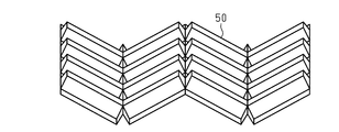
- this hollow structure includes a core layer obtained by folding a sheet material 50 having irregularities, and two skin layers respectively bonded to both surfaces of the core layer.
- a plurality of cells are arranged in the hollow structure.
- the partition wall located between adjacent cells has a two-layer structure.
- One of the ends of the partition wall has a joining part in which two layers are joined to each other, and the other end has a folding part.
- An object of the present disclosure is to provide a hollow structure body having improved impact resistance efficiently.
- the hollow structure has a plurality of cells.
- the hollow structure includes a core layer having a plurality of first walls, a plurality of second walls and a plurality of partition walls, and first and second skin layers respectively bonded to both surfaces of the core layer.
- the plurality of cells include a plurality of first cells and a plurality of second cells. Each of the first cells is partitioned by the first wall, the plurality of partition walls extending from the first wall, and the second skin layer. Each of the second cells is partitioned by the second wall, the plurality of partition walls extending from the second wall, and the first skin layer.
- the plurality of first cells arranged in one direction is a first cell row
- the plurality of second cells arranged in one direction is a second cell row
- the plurality of partition walls are a plurality of first partition walls having a two-layer structure located between the adjacent first cells of the first cell row, and the adjacent second cells of the second cell row.
- a plurality of second partition walls each having a two-layer structure located between the plurality of second partition walls.
- the first partition wall has, at an end closer to the first wall, a first joint portion in which two layers constituting the first partition wall are joined to each other, and is far from the first wall. It has a first folded portion at one end.
- the second partition wall has, at an end closer to the second wall, a second bonding portion in which two layers forming the second partition wall are bonded to each other, and is far from the second wall. It has a second folded portion at one end.
- the joining force of the first joining portion is larger than the joining force of the second joining portion.
- FIG. 1A The perspective view of the hollow structure body concerning an embodiment. Sectional drawing which followed the 1B-1B line of FIG. 1A. Sectional drawing which followed the 1C-1C line of FIG. 1A.
- seat material of FIG. 2A The perspective view which shows the state which folded the sheet
- FIG. 8 is an end view taken along line 8-8 of FIG.
- FIG. 9 is an end view taken along the line 9-9 of FIG. 6.
- the hollow structure 10 includes a core layer 20 and first and second skin layers 30 and 40 bonded (for example, welded) to both surfaces of the core layer 20.
- the core layer 20 has a plurality of first walls 21a, a plurality of second walls 21b, and a plurality of partition walls 23, and partitions a plurality of cells S having a hexagonal prism shape.
- the plurality of cells S include a plurality of first cells S1 and a plurality of second cells S2.
- Each first cell S1 is partitioned by a hexagonal first wall 21a, a plurality of partition walls 23 extending from the first wall 21a toward the second skin layer 40, and a second skin layer 40.
- Each second cell S2 is partitioned by a hexagonal second wall 21b, a plurality of partition walls 23 extending from the second wall 21b toward the first skin layer 30, and a first skin layer 30.
- the core layer 20 includes a plurality of first cell rows S1a in which a plurality of first cells S1 are arranged in one direction (X axis) and a plurality of a plurality of second cells S2 arranged in one direction (X axis). And a second cell row S2a.
- the X axis, the Y axis, and the Z axis are direction axes orthogonal to each other, and the thickness direction of the hollow structure 10 is a direction along the Z axis.
- the first and second cell rows S1a and S2a extend in a direction orthogonal to the thickness direction Z.
- the plurality of partition walls 23 include a plurality of first partition walls 23a, a plurality of second partition walls 23b, and a plurality of third partition walls 23c.
- the first and second partition walls 23a and 23b have a two-layer structure.
- the third partition wall 23c has a one-layer structure.
- the first partition wall 23a is located between the adjacent first cells S1 of the first cell row S1a.
- the first partition wall 23a has a first end (an end closer to the first wall 21a) in the thickness direction Z, in which the surfaces of the two layers forming the first partition wall 23a are joined to each other by welding.
- the joint portion 24a is provided, and the first folded portion 25a is provided at the second end (the end farther from the first wall 21a) in the thickness direction Z.
- the two layers forming the first partition wall 23a are not joined to each other between the first joint portion 24a and the first folded portion 25a.
- the second partition wall 23b is located between the adjacent second cells S2 of the second cell row S2a.
- the second partition wall 23b has a second joint portion 24b in which two layers constituting the second partition wall 23b are joined to each other by welding at a second end (an end closer to the second wall 21b) in the thickness direction Z. And has the second folded portion 25b at the first end (the end farther from the second wall 21b) in the thickness direction Z.
- the two layers forming the second partition wall 23b are not joined to each other between the second joint portion 24b and the second folded portion 25b.
- the two layers forming the first partition wall 23a are not joined to each other near the center in the thickness direction Z. Therefore, the first communication portion 26a that allows the first cells S1 to communicate with each other may be formed between the first cells S1 adjacent to each other in the Y direction. Similarly, the two layers forming the second partition wall 23b are not joined to each other near the center in the thickness direction Z. Therefore, the second communicating portion 26b that allows the second cells S2 to communicate with each other may be formed between the second cells S2 adjacent to each other in the Y direction.
- the first communication portion 26a is a gap that can be formed between two first partition walls 23a that are adjacent to or in contact with each other.
- the second communication portion 26b is a gap that can be formed between two adjacent second partition walls 23b. That is, the unbonded portions of the two layers may allow fluid to flow between the two layers, even though they appear to be in contact with each other.
- the third partition wall 23c is located between the first cell S1 and the second cell S2.
- the first cell row S1a and the second cell row S2a are alternately arranged along the Y axis orthogonal to the X axis while sharing the plurality of third partition walls 23c.
- the six partition walls 23 that partition each first cell S1 include two first partition walls 23a and four third partition walls 23c, and the six partition walls 23 that partition each second cell S2 are 2 It includes one second partition wall 23b and four third partition walls 23c.
- the core layer 20 and the skin layers 30 and 40 are made of thermoplastic resin.
- the thermoplastic resin forming the core layer 20 and the skin layers 30 and 40 is well known in the art, and the material thereof is not particularly limited. Examples of the thermoplastic resin are polypropylene resin, polyamide resin, polyethylene resin, acrylonitrile-butadiene-styrene copolymer resin, acrylic resin, polybutylene terephthalate resin and the like.
- the thermoplastic resins forming the core layer 20 and the skin layers 30 and 40 may be made of the same material or may be different from each other.
- the core layer 20 and the skin layers 30 and 40 of this embodiment are both made of polypropylene resin.
- the thickness of the first wall 21a, the partition wall 23, and the second wall 21b of the core layer 20 is not particularly limited, but is, for example, 0.1 mm to 0.5 mm.
- the thickness of the skin layers 30 and 40 is not particularly limited, but is, for example, 0.3 mm to 0.6 mm.
- the thickness of the first wall 21a may be thicker than the thickness of the second wall 21b.
- the method for manufacturing the hollow structure 10 includes a folding step, a heating step, and a laminating step.
- a flat sheet material 200 as shown in FIG. 2A is formed by folding to form a core layer.
- the sheet material 200 is vacuum formed so as to have a predetermined unevenness.
- the sheet material 200 includes band-shaped first and second bulging portions 210 and 220 extending in the X direction.
- the first bulging portions 210 and the second bulging portions 220 have a width in the Y direction and are arranged alternately along the Y axis.
- the first bulging portion 210 and the second bulging portion 220 project in opposite directions along the Z axis.
- the first bulging portion 210 and the second bulging portion 220 have the same shape and are arranged at positions shifted by 1/2 pitch along the X axis. There is.
- the first bulging portion 210 has a first bulging surface 210a, two section screens 210b, and two end surfaces 210c.
- the cross-sectional shape of the first bulging portion 210 taken along a plane including the Y axis and the Z axis is a trapezoid obtained by dividing the regular hexagon by the longest diagonal line.
- the two end faces 210c are located at the boundary line P′ shown in FIG. 2A.
- the angle formed by the end surface 210c and the first bulging surface 210a is about 90°.
- the second bulging portion 220 has a second bulging surface 220a, two section screens 220b, and two end surfaces 220c.
- the cross-sectional shape of the second bulging portion 220 taken along a plane including the Y axis and the Z axis is a trapezoid obtained by dividing the regular hexagon by the longest diagonal line.
- the two end faces 220c are located at the boundary line Q′ shown in FIG. 2A.
- the angle formed by the end surface 220c and the second bulging surface 220a is about 90°.
- the length of the second bulging portion 220 along the X axis, that is, the length between the two end surfaces 220c is the length of the first bulging portion 210 along the X axis, that is, the length between the two end surfaces 210c. Is the same.
- the end surface 220c of the second bulging portion 220 is located at the center of the first bulging portion 210 in the X direction.
- the division screen 210b of the first bulging portion 210 and the division screen 220b of the second bulging portion 220 have the same shape.
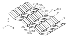
- the core layer 20 is formed by sequentially folding the sheet material 200 along the boundary lines P′ and Q′.
- the sheet material 200 is mountain-folded along the boundary line P′ and valley-folded along the boundary line Q′.
- the first bulging portion 210 is valley-folded at a boundary line Q′ located at the center in the X direction, and the first bulging surfaces 210a that are divided with the boundary line Q′ as a boundary are separated from each other. Abut.
- the first bulging surfaces 210a that are in contact with each other serve as the first partition wall 23a
- the partition screen 210b serves as the third partition wall 23c.
- the two end faces 210c arranged along the X-axis form the first wall 21a having a single-layer structure.
- the second end (lower end in FIG. 2C) of the first partition wall 23a defines the first opening 27a.
- the second bulging portion 220 is mountain-folded at a boundary line P′ located at the center of the adjacent boundary lines Q′ in the X direction, and the second bulging surfaces 220 a that are divided with the boundary line P′ as a boundary are separated from each other. Abut. In the thus-folded second bulging portion 220, the second bulging surfaces 220a that are in contact with each other serve as the second partition wall 23b, and the partition screen 220b serves as the third partition wall 23c. At the second end (lower end in FIG. 2C) of the second partition wall 23b, the two end surfaces 220c arranged along the X-axis form the second wall 21b having a single-layer structure. The first end (upper end in FIG. 2C) of the second partition wall 23b defines the second opening 27b.
- the first cell S1 having the first opening 27a is divided by the first wall 21a and the partition wall 23 extending from the first wall 21a, and the second wall 21b and the second wall 21b are formed.
- the partition wall 23 extending from 21b partitions the second cell S2 having the second opening 27b.
- the surfaces of the first wall 21a and the second wall 21b are smooth surfaces.
- the “smooth surface” means a flat surface that has no unevenness when visually observed.
- the thickness of the portion where the amount of deformation due to evacuation is large becomes thinner than the thickness of the other portions. Therefore, when the sheet material 200 is evacuated, the second bulging portion 220 is evacuated more strongly in the bulging direction, so that the thickness of the second wall 21b becomes smaller than the thickness of the first wall 21a. As a result, the thickness of the first wall 21a can be made relatively thicker than the thickness of the second wall 21b.
- the thickness of the first wall 21a is not particularly limited, but may be, for example, twice or more the thickness of the second wall 21b.
- the thickness of the partition wall 23 gradually increases from the second surface of the core layer 20 toward the first surface.
- the plurality of cells S are neatly aligned along the X axis and the Y axis.
- the thickness of the partition wall 23 near the second surface of the core layer 20 is smaller than that near the first surface. Therefore, on the second surface of the core layer 20, the plurality of cells S arranged along the Y axis are arranged so as to meander slightly. At this time, in the vicinity of the second surface of the core layer 20, the crushing amount of the two layers forming the partition wall 23 can be increased to bring the two layers into close contact with each other. Therefore, in the heating step described later, the two layers forming the partition wall 23 can be more reliably welded to each other near the second surface.
- a plurality of cells S arranged along the Y axis may be arranged in a meandering manner.
- Heating process In the heating step, the core layer 20 produced in the folding step is pressed while being heated. As a result, the first end of the first partition wall 23a is heat-welded (hereinafter, also simply referred to as "welding"), and the second end of the second partition wall 23b is heat-welded.
- a method of heating the core layer 20 by a heating device while conveying the core layer 20 by a conveyor can be adopted.
- the first and second surfaces of the core layer 20 are sandwiched between the first and second conveyors, respectively, and the core layer 20 is heated by a heater arranged inside the first and second conveyors.
- the core layer 20 is conveyed along the X axis.
- a load is applied to the core layer 20 along the X axis.
- a load may be applied to the core layer 20 along the Z axis by sandwiching the core layer 20 between the first and second conveyors arranged along the Z axis.
- the two layers forming the first partition wall 23a are welded to each other near the first wall 21a.
- the first joint portion 24a is formed.
- the two layers forming the first partition wall 23a are welded to each other near the second wall 21b.
- the second joint portion 24b is formed.
- the thickness of the partition wall 23 near the first wall 21a is thicker than the thickness near the second wall 21b. Therefore, when the core layer 20 is pressed from both sides, a relatively larger load is applied to the vicinity of the first wall 21a than to the vicinity of the second wall 21b. That is, the length dimension along the X axis of the core layer 20 obtained by the folding step is longer at the position in contact with the first wall 21a than at the position in contact with the second wall 21b. Therefore, the load applied to the core layer 20 by the first and second conveyors becomes larger at the first end of the first partition wall 23a. By welding under a larger load, the joining force becomes larger. Therefore, the joining force of the first joining portion 24a is larger than the joining force of the second joining portion 24b.
- the first and second sheets are joined to the first and second surfaces of the core layer 20, respectively. More specifically, the first and second sheets to be the skin layers 30 and 40 are heated and brought into contact with both surfaces of the core layer 20 for a predetermined time. As a result, the first and second skin layers 30 and 40 are joined (welded) to both surfaces of the core layer 20, respectively.
- the flat hollow structure 10 including a plurality of cells S is manufactured through the above manufacturing steps.
- the use of the hollow structure 10 is not particularly limited. Since the hollow structure 10 has a honeycomb structure, it has excellent impact resistance, sound insulation, and heat insulation. Therefore, the hollow structure 10 can be appropriately used for applications requiring these characteristics. Examples of applications of the hollow structure 10 are luggage boards, shelves, containers, and the like.
- the first skin layer 30 may be the surface or the second skin layer 40 may be the surface.
- the cell in which the plurality of cells S are neatly aligned may be bonded to the skin layer, or the plurality of cells S are arranged in a slightly meandering manner. It may be bonded to a skin layer of which one is the surface.
- the hollow structure 10 can improve the impact resistance from one surface side, that is, the side where the first joint portion 24a is provided in the thickness direction. Therefore, impact resistance can be efficiently improved.
- the bending strength of the hollow structure 10 can be improved as compared with a mode in which the joining force of the first joining portion 24a is the same as the joining force of the second joining portion 24b.
- the thickness of the first wall 21a is relatively thicker than the thickness of the second wall 21b. This is because the wall thickness of the end face 210c of the sheet material 200 that becomes the core layer 20 is relatively thicker than the wall thickness of the end face 220c. Therefore, the strength of the first wall 21a can be relatively increased. Therefore, in the hollow structure 10, the impact resistance from the first surface side in the thickness direction, that is, the side where the first joint portion 24a is provided is further improved.
- the thickness of the first end (the end that intersects the first wall 21a) of the partition wall 23 is relatively thicker than the thickness of the second end (the end that intersects the second wall 21b).
- the intersecting portion between the partition wall 23 and the first wall 21a can be crushed a little and the intersecting portion can be more reliably joined (for example, welded) to the first skin layer 30. That is, even if the vicinity of the first end of the partition wall 23 is slightly crushed, the strength of the partition wall 23 itself is secured, and therefore it is possible to prevent the partition wall 23 from being crushed excessively.
- the partition wall 23 has a thickness that continuously decreases from the first end toward the second end.
- the thickness of the first end of the partition wall 23 is thicker than the thickness of the second end. Therefore, for example, when the core layer 20 is heated from both sides, the amount of resin melted near the first end of the partition wall 23 is larger than the amount of resin melted near the second end. As a result, a large amount of resin that is melted by heating can be secured, and the first end of the partition wall 23 can be more reliably welded. On the other hand, since the second end of the partition wall 23 is relatively thin, it is easily heated by the heat from the heating device. Therefore, the second end of the partition wall 23 can be efficiently heated and more reliably welded.
- the first cell row S1a and the second cell row S2a are arranged alternately. Therefore, the impact resistance can be made more uniform on both surfaces of the hollow structure 10.
- the first joint portion 24a is a portion where the two layers forming the first partition wall 23a are welded to each other
- the second joint portion 24b is the portion where the two layers forming the second partition wall 23b are welded to each other. Is. Therefore, the configurations of the first joint portion 24a and the second joint portion 24b can be simplified.
- the first communication portion 26a is formed between the first cells S1 adjacent to each other in the Y direction
- the second communication portion 26b is formed between the second cells S2 adjacent to each other in the Y direction. Therefore, when the hollow structure 10 is heated and bent, the heated air in the first cell S1 and the second cell S2 passes through the first communication portion 26a and the second communication portion 26b. And spreads over the entire hollow structure 10. Thereby, expansion of the 1st wall 21a and the 2nd wall 21b can be controlled.
- the present embodiment can be implemented with the following modifications.
- the configurations included in the present embodiment and the following modifications can be implemented in combination with each other within a technically consistent range.
- the first joint portion 24a and the second joint portion 24b may be formed.
- the joining force of the first joining portion 24a and the joining force of the second joining portion 24b can be changed by adjusting the type of the adhesive and the application state of the adhesive.
- the core layer 20 may not have at least one of the first communication portion 26a and the second communication portion 26b.
- the two layers forming the first partition wall 23a may be joined at their entire surfaces to each other.
- the two layers forming the second partition wall 23b may be joined at their entire surfaces to each other.
- the hollow structure 10 does not have to be a flat plate. At least a part of the hollow structure 10 may be curved so that the outer surface defined by the first skin layer 30 is a convex surface and the outer surface defined by the second skin layer 40 is a concave surface.
- the hollow structure 10 can be curved as described above by press molding after the laminating step. Thereby, impact resistance from the convex surface side of the hollow structure 10 is improved.
- the outer surface defined by the first skin layer 30 may be a concave surface and the outer surface defined by the second skin layer 40 may be a convex surface.
- a curved portion can be formed at an arbitrary position by press-molding a part of the hollow structure 10 after the laminating step.
- the height dimension of the convex surface 31 and the depth dimension of the concave surface 41 may be larger than the thickness dimension of the flat portion of the hollow structure 10.
- the hollow structure 10 may have a plurality of curved portions. In this case, the hollow structure 10 may have a plurality of bending portions that bend in different directions.
- At least one of the first wall 21a and the second wall 21b may have an uneven shape or an uneven pattern on the outer surface.
- Such a concavo-convex shape can generate an anchor effect when joining (for example, welding) the sheets to be the skin layer. Therefore, the bonding strength of the skin layers 30 and 40 can be further increased. By increasing the joint strength of the skin layers 30 and 40, the impact resistance of the hollow structure 10 can be improved.
- the first wall 21a (end surface 210c) of the core layer 20 may have a linear recess 28a extending along the Y axis.
- the recess 28a is recessed in the direction in which it is pulled during vacuum forming.
- the recessed portion 28a can increase the welding area between the core layer 20 and the skin layers 30 and 40.
- the second wall 21b (end surface 220c) of the core layer 20 may have a plurality of wrinkle-shaped recesses 28b extending along the Y axis. Since the wall thickness of the end surface 220c is relatively thin, it is easily softened by heating in the heating process.
- the recess 28b can be formed by setting a higher heating temperature in the heating process.
- one of the first and second openings 27a and 27b does not have to be a regular hexagon.
- the position of the first cell row S1a along the X axis is displaced, so that the shape of the second opening 27b is distorted and is not a regular hexagon.
- the cells S1 and S2 arranged alternately along the Y axis appear to meander.
- FIG. 7 schematically shows a die 251 for vacuum forming the sheet material 200 and the sheet material 200 immediately after vacuum forming.
- the mold 251 has a plurality of suction holes 252 for sucking the sheet material 200.
- the mold 251 may be a cylindrical drum.
- the long sheet material 200 can be continuously formed by transporting the sheet material 200 while being wound around the cylindrical mold 251.
- the second bulging portion 220 is extended by being sucked by the mold 251 through the suction hole 252 as shown by the white arrow in FIG. 7. As a result, the second bulging portion 220 is relatively thinner than the first bulging portion 210. At this time, the intersection of the second bulging surface 220a, the two division screens 220b, and the two end surfaces 220c may not be a sharp corner. In this case, the second bulging surface 220a, the two section screens 220b, and the two end surfaces 220c of the second bulging portion 220 are curved so as to bulge outward toward the mold 251, and the second bulging portion 220 has four bulging portions. Has rounded corners.
- the first bulging surface 210a of the first bulging portion 210, the two ward screens 210b (the ward screen 220b) and the two end faces 210c are curved so as to dent inward toward the mold 251 and the first bulge is performed.
- Portion 210 has four sharp corners.
- the two first bulging surfaces 210a forming the first partition wall 23a are curved so that their outer edges are close to each other.
- the plurality of first walls 21a and the plurality of first openings 27a are regular hexagons
- the plurality of second walls 21b and the plurality of second openings 27b are distorted hexagons.
- the plurality of first walls 21a and the plurality of second openings 27b are distorted hexagons.
- the meandering state of the cell S changes depending on which of the first wall 21a and the second wall 21b is a regular hexagon. Even when the plurality of cells S are distorted or meandered, each cell S maintains the hexagonal prism shape, and thus impact strength and bending strength are less likely to decrease.
- the distortion and meandering of the plurality of cells S may occur due to, for example, the first bulging surface 210a being curved or the second bulging portion 220 having a rounded corner.
- the core layer 20 can be formed while the cells S are distorted and meandered. Therefore, it is possible to increase the molding speed of the sheet material 200 and the core layer 20 to improve work efficiency, and to suppress the occurrence of defective molding of the sheet material 200 and the core layer 20.
- the two second bulging surfaces 220a forming the second partition wall 23b may be curved so that the centers of the surfaces approach each other. In this case, the impact resistance of the second partition wall 23b is improved.
- At least one of the first wall 21a and the second wall 21b may have a convex portion.
- the convex portion 110 of the first wall 21a was melted and projected by increasing the heating temperature or the pressing force in the heating step. It is a part.
- the protrusion 110 may protrude in a direction in which the first surface 20a of the core layer 20 (a surface joined to the first skin layer 30) extends, or may protrude in a direction intersecting with the first surface 20a. The protrusion 110 allows the core layer 20 to be more reliably welded to the first skin layer 30.
- the convex portion 111 protruding from the first folded portion 25a may be formed by heating or pressing the first folded portion 25a.
- the convex portion 111 is a portion for welding the first partition wall 23a (first folded portion 25a) to the second skin layer 40. As a result, the welding area of the core layer 20 to the second skin layer 40 increases, and the welding strength increases.
- the convex portion 113 of the second wall 21b is a portion where the second wall 21b is melted and protrudes.
- the protrusion 113 may protrude in the direction in which the second surface 20b (the surface joined to the second skin layer 40) of the core layer 20 extends, or may protrude in the direction intersecting with the second surface 20b.
- the protrusion 113 allows the core layer 20 to be more reliably welded to the second skin layer 40.
- the convex portion 112 protruding from the second folded portion 25b may be formed by heating or pressing the second folded portion 25b.
- the convex 112 serves as a portion for welding the second partition wall 23b (second folded portion 25b) to the first skin layer 30.
- the welding area of the core layer 20 with respect to the first skin layer 30 increases, so that the welding strength increases.
- the opening areas of the first and second opening portions 27a and 27b can be narrowed by projecting the protruding portions 111 and 112 from the folded-back portions 25a and 25b, respectively. Therefore, the welding strength of the skin layers 30 and 40 is improved.
- the skin layers 30 and 40 may be attached to both sides of the core layer 20 with an adhesive.
- the adhesive may be applied to the sheets that will be the skin layers 30 and 40, or may be applied to the core layer 20.
- the skin layers 30 and 40 may be non-woven fabric, for example. Alternatively, a nonwoven fabric may be attached to the outer surfaces of the skin layers 30 and 40.
- the hollow structure 10 may have a through hole that penetrates at least one of the core layer 20 and the skin layers 30 and 40 in the thickness direction (Z direction).
- the shape of the cell S included in the hollow structure 10 is not limited to a hexagonal column, and may be, for example, any polygonal column, a circle, or an elliptic column.
- the outer edge of the hollow structure 10 may be crushed so that the first skin layer 30 approaches the second skin layer 40.
- the outer edge of the first skin layer 30 and the outer edge of the first wall 21 a are curved so as to approach the first skin layer 30.
- the crushed outer edge portion 105, the first skin layer 30, the first wall 21a, and the partition wall 23 are integrated into a solid shape.
- the first partition wall 23a is crushed near the thickest first end. Therefore, the strength of the solid outer edge portion 105 is higher and the surface of the outer edge portion 105 is smoother than when the vicinity of the second end where the thickness of the first partition wall 23a is relatively thin is crushed.
Landscapes
- Engineering & Computer Science (AREA)
- Mechanical Engineering (AREA)
- Laminated Bodies (AREA)
- Panels For Use In Building Construction (AREA)
- Vehicle Step Arrangements And Article Storage (AREA)
Priority Applications (3)
| Application Number | Priority Date | Filing Date | Title |
|---|---|---|---|
| JP2020571285A JP7548568B2 (ja) | 2019-02-08 | 2020-02-07 | 中空構造体及びラゲッジボード |
| JP2024141007A JP7790762B2 (ja) | 2019-02-08 | 2024-08-22 | 中空構造体及びラゲッジボード |
| JP2025230779A JP2026026343A (ja) | 2019-02-08 | 2025-12-04 | 中空構造体及びラゲッジボード |
Applications Claiming Priority (2)
| Application Number | Priority Date | Filing Date | Title |
|---|---|---|---|
| JP2019-021822 | 2019-02-08 | ||
| JP2019021822 | 2019-02-08 |
Publications (1)
| Publication Number | Publication Date |
|---|---|
| WO2020162590A1 true WO2020162590A1 (ja) | 2020-08-13 |
Family
ID=71948346
Family Applications (1)
| Application Number | Title | Priority Date | Filing Date |
|---|---|---|---|
| PCT/JP2020/004762 Ceased WO2020162590A1 (ja) | 2019-02-08 | 2020-02-07 | 中空構造体及びラゲッジボード |
Country Status (2)
| Country | Link |
|---|---|
| JP (3) | JP7548568B2 (https=) |
| WO (1) | WO2020162590A1 (https=) |
Cited By (1)
| Publication number | Priority date | Publication date | Assignee | Title |
|---|---|---|---|---|
| WO2023013625A1 (ja) * | 2021-08-05 | 2023-02-09 | MT-Tec合同会社 | 積層中空成形体 |
Citations (5)
| Publication number | Priority date | Publication date | Assignee | Title |
|---|---|---|---|---|
| JP2008520456A (ja) * | 2004-11-19 | 2008-06-19 | カー・イュー・ルーベン・リサーチ・アンド・ディベロップメント | 半閉型の熱可塑性ハニカム体、その製造工程および製造装置 |
| WO2010119946A1 (ja) * | 2009-04-16 | 2010-10-21 | 岐阜プラスチック工業 株式会社 | 構造体及び成形品並びにそれらの製造方法 |
| JP2013237242A (ja) * | 2012-05-17 | 2013-11-28 | Toray Ind Inc | ハニカム構造体およびサンドイッチ構造体 |
| WO2016031479A1 (ja) * | 2014-08-29 | 2016-03-03 | 三菱瓦斯化学株式会社 | ハニカム用基材、ハニカム構造体及びサンドイッチ構造体 |
| JP2017124793A (ja) * | 2016-01-15 | 2017-07-20 | 岐阜プラスチック工業株式会社 | 自動車用内装板材 |
Family Cites Families (1)
| Publication number | Priority date | Publication date | Assignee | Title |
|---|---|---|---|---|
| JP7120612B2 (ja) * | 2018-07-20 | 2022-08-17 | 岐阜プラスチック工業株式会社 | 中空構造体及びその製造方法 |
-
2020
- 2020-02-07 WO PCT/JP2020/004762 patent/WO2020162590A1/ja not_active Ceased
- 2020-02-07 JP JP2020571285A patent/JP7548568B2/ja active Active
-
2024
- 2024-08-22 JP JP2024141007A patent/JP7790762B2/ja active Active
-
2025
- 2025-12-04 JP JP2025230779A patent/JP2026026343A/ja active Pending
Patent Citations (5)
| Publication number | Priority date | Publication date | Assignee | Title |
|---|---|---|---|---|
| JP2008520456A (ja) * | 2004-11-19 | 2008-06-19 | カー・イュー・ルーベン・リサーチ・アンド・ディベロップメント | 半閉型の熱可塑性ハニカム体、その製造工程および製造装置 |
| WO2010119946A1 (ja) * | 2009-04-16 | 2010-10-21 | 岐阜プラスチック工業 株式会社 | 構造体及び成形品並びにそれらの製造方法 |
| JP2013237242A (ja) * | 2012-05-17 | 2013-11-28 | Toray Ind Inc | ハニカム構造体およびサンドイッチ構造体 |
| WO2016031479A1 (ja) * | 2014-08-29 | 2016-03-03 | 三菱瓦斯化学株式会社 | ハニカム用基材、ハニカム構造体及びサンドイッチ構造体 |
| JP2017124793A (ja) * | 2016-01-15 | 2017-07-20 | 岐阜プラスチック工業株式会社 | 自動車用内装板材 |
Cited By (1)
| Publication number | Priority date | Publication date | Assignee | Title |
|---|---|---|---|---|
| WO2023013625A1 (ja) * | 2021-08-05 | 2023-02-09 | MT-Tec合同会社 | 積層中空成形体 |
Also Published As
| Publication number | Publication date |
|---|---|
| JP7548568B2 (ja) | 2024-09-10 |
| JP2024152938A (ja) | 2024-10-25 |
| JPWO2020162590A1 (https=) | 2020-08-13 |
| JP7790762B2 (ja) | 2025-12-23 |
| JP2026026343A (ja) | 2026-02-16 |
Similar Documents
| Publication | Publication Date | Title |
|---|---|---|
| CN107031142B (zh) | 层叠结构体及其制造方法 | |
| CN110785281B (zh) | 板材 | |
| JPS63224927A (ja) | 熱可塑性樹脂部材の積層方法 | |
| JP6659020B2 (ja) | 中空積層板及びその端部処理方法 | |
| WO2010119946A1 (ja) | 構造体及び成形品並びにそれらの製造方法 | |
| JP2026026343A (ja) | 中空構造体及びラゲッジボード | |
| JP7651210B2 (ja) | 中空構造体 | |
| JP7204172B2 (ja) | 中空板材 | |
| JP7398081B2 (ja) | 中空構造体 | |
| CN207388437U (zh) | 层叠板 | |
| JP6235254B2 (ja) | 中空構造パネル | |
| CN114333593A (zh) | 折叠屏支撑板、折叠屏支撑板的制造方法以及折叠屏 | |
| JPH07156319A (ja) | 曲面ハニカムパネル | |
| JP7391352B2 (ja) | 中空構造体及び中空構造体の製造方法 | |
| JP6684595B2 (ja) | 積層構造体 | |
| JP7391358B2 (ja) | 中空構造体 | |
| JP7201200B2 (ja) | 防音パネル及びその製造方法 | |
| JP6990919B2 (ja) | 中空構造体及びその製造方法 | |
| KR101629310B1 (ko) | 중공 구조체 | |
| CN113498373A (zh) | 中空结构体及其制造方法 | |
| WO2019203194A1 (ja) | 中空構造体及びその製造方法 | |
| JPH06278933A (ja) | 綴じ合わせ紙工品および綴じ合わせ加工用金型 | |
| JP7365673B2 (ja) | 中空構造体 | |
| JP7406810B2 (ja) | 中空構造体及び中空構造体の製造方法 | |
| JP7271007B2 (ja) | 中空構造体の製造方法 |
Legal Events
| Date | Code | Title | Description |
|---|---|---|---|
| 121 | Ep: the epo has been informed by wipo that ep was designated in this application |
Ref document number: 20752705 Country of ref document: EP Kind code of ref document: A1 |
|
| NENP | Non-entry into the national phase |
Ref country code: DE |
|
| ENP | Entry into the national phase |
Ref document number: 2020571285 Country of ref document: JP Kind code of ref document: A |
|
| 122 | Ep: pct application non-entry in european phase |
Ref document number: 20752705 Country of ref document: EP Kind code of ref document: A1 |