WO2020162481A1 - 走行車両 - Google Patents
走行車両 Download PDFInfo
- Publication number
- WO2020162481A1 WO2020162481A1 PCT/JP2020/004284 JP2020004284W WO2020162481A1 WO 2020162481 A1 WO2020162481 A1 WO 2020162481A1 JP 2020004284 W JP2020004284 W JP 2020004284W WO 2020162481 A1 WO2020162481 A1 WO 2020162481A1
- Authority
- WO
- WIPO (PCT)
- Prior art keywords
- oil
- gear
- storage chamber
- synchronizer ring
- traveling vehicle
- Prior art date
- Legal status (The legal status is an assumption and is not a legal conclusion. Google has not performed a legal analysis and makes no representation as to the accuracy of the status listed.)
- Ceased
Links
Images





Classifications
-
- F—MECHANICAL ENGINEERING; LIGHTING; HEATING; WEAPONS; BLASTING
- F16—ENGINEERING ELEMENTS AND UNITS; GENERAL MEASURES FOR PRODUCING AND MAINTAINING EFFECTIVE FUNCTIONING OF MACHINES OR INSTALLATIONS; THERMAL INSULATION IN GENERAL
- F16D—COUPLINGS FOR TRANSMITTING ROTATION; CLUTCHES; BRAKES
- F16D23/00—Details of mechanically-actuated clutches not specific for one distinct type
- F16D23/02—Arrangements for synchronisation, also for power-operated clutches
- F16D23/04—Arrangements for synchronisation, also for power-operated clutches with an additional friction clutch
- F16D23/06—Arrangements for synchronisation, also for power-operated clutches with an additional friction clutch and a blocking mechanism preventing the engagement of the main clutch prior to synchronisation
-
- F—MECHANICAL ENGINEERING; LIGHTING; HEATING; WEAPONS; BLASTING
- F16—ENGINEERING ELEMENTS AND UNITS; GENERAL MEASURES FOR PRODUCING AND MAINTAINING EFFECTIVE FUNCTIONING OF MACHINES OR INSTALLATIONS; THERMAL INSULATION IN GENERAL
- F16H—GEARING
- F16H57/00—General details of gearing
- F16H57/04—Features relating to lubrication or cooling or heating
Definitions
- the present invention relates to a traveling vehicle.
- the power transmission device is, for example, a forward/reverse switching device that switches between forward and backward travel of a traveling vehicle.
- the power transmission device has a gear and a synchronizer ring that contacts the gear.
- the shifter pushes the synchronizer ring toward the gear side by the switching operation of the gear by the driver, and the gear and the synchronizer ring come into contact with each other. Due to the friction generated by this contact, the rotation speeds of the gear and the synchronizer ring match, and the rotation of the shaft is transmitted to the gear via the synchronizer ring.
- oil (mission oil) is stored in the case.
- the power transmission device in particular, the synchronizer ring
- the oil enters between the gear and the synchronizer ring.
- the oil reduces friction between the gear and the synchronizer ring, and suppresses wear of the synchronizer ring.
- a traveling vehicle includes an engine, a case in which a power transmission device that transmits power from the engine is housed, and a housing space of the case, and the inside of the case is outside the case. And a supply pipe for supplying oil.
- the power transmission device includes a gear and a synchronizer ring that contacts the gear.
- the supply pipe includes a tubular body through which the oil flows, a discharge port through which the oil is discharged, and a guide unit that guides the oil discharged through the discharge port between the gear and the synchronizer ring. And.
- the oil supplied by the supply pipe is guided between the gear and the synchronizer ring by the guide portion, so that the oil is applied to the contact surface of the synchronizer ring that contacts the gear. Therefore, even when the synchronizer ring is not immersed in oil, the lubrication between the gear and the synchronizer ring can be maintained, and the wear of the synchronizer ring can be suppressed.
- the guide portion is tubular.
- the guide portion extends from the main body portion between the gear and the synchronizer ring.
- the discharge port is provided at an end of the guide portion in the extending direction.
- the oil discharged from the discharge port facing the gear is discharged in the extending direction of the guide portion. Since the guide portion extends toward between the gear and the synchronizer ring, the discharged oil can be accurately applied between the gear and the synchronizer ring. As a result, the lubrication between the gear and the synchronizer ring can be maintained.
- the discharge port is arranged above the central axis of the shaft to which the gear is attached.
- the oil can be applied to the upper side of the gear that is hard to be immersed in the oil, and the lubrication between the gear and the synchronizer ring can be maintained.
- the main body portion extends so as not to vertically overlap with the central axis of the shaft.
- an angle formed by an imaginary line passing through the center of the outlet and the central axis of the shaft and the extending direction of the guide portion is less than 30 degrees.
- the extending direction of the guide portion is inclined with respect to the vertical direction.
- the power transmission device includes a mechanical forward/reverse switching device that switches between forward and backward travel of the traveling vehicle.
- the gear is a gear of the forward/reverse switching device.
- a work using a traveling vehicle for example, farming work
- switching between forward and reverse is often performed, so the number of shifts of the forward/reverse switching device is larger than the number of shifts of the transmission. .. Therefore, the synchronizer ring that comes into contact with the gear of the forward/reverse switching device is more easily worn than the synchronizer ring that comes into contact with the gear of the transmission. Therefore, by guiding oil between the gear of the forward/reverse switching device and the synchronizer ring, it is possible to suppress wear of the synchronizer ring, which is easily worn.
- the forward/reverse switching device has a forward gear and a reverse gear as the gears.
- the synchronizer ring includes a first synchronizer ring that contacts the forward gear and a second synchronizer ring that contacts the reverse gear.
- the guide portion guides the oil between the forward gear and the first synchronizer ring and a second guide portion that guides the oil between the reverse gear and the second synchronizer ring. And a section. Since oil is applied to each of the first synchronizer ring that contacts the forward gear and the second synchronizer ring that contacts the reverse gear, wear of both synchronizer rings can be suppressed.
- the traveling vehicle has a transmission that shifts the power from the engine and transmits the power to the drive wheels.
- the case is located between a first accommodation chamber in which the forward/reverse switching device is accommodated, a second accommodation chamber in which the transmission is accommodated, and the second accommodation chamber of the first accommodation chamber. And a case wall portion that separates the first storage chamber and the second storage chamber from each other.
- the supply pipe supplies the oil to the first storage chamber. While the oil is being supplied, the oil level of the oil in the first storage chamber becomes higher than that before the oil is supplied. As a result, at least a part of the synchronizer ring of the forward/reverse switching device is easily immersed in oil. As a result, wear of the synchronizer ring can be further suppressed.
- the case wall portion is provided with an opening that penetrates the first storage chamber and the second storage chamber.
- the traveling vehicle includes a shaft that is disposed in the first storage chamber and that is rotated by power from the engine, and a bearing in which the shaft is inserted.
- the bearing is fixed to the case wall so as to close the opening. Since the bearing is fixed so as to close the opening, the flow rate of the oil flowing from the first storage chamber to the second storage chamber through the opening is limited.
- the case wall is provided with the opening, it is easy to store oil in the first storage chamber, and at least a part of the synchronizer ring of the forward/reverse switching device is easily immersed in oil. As a result, wear of the synchronizer ring can be further suppressed.
- the bearing has an inner ring, an outer ring, a rolling element, and a seal portion that closes between the inner ring and the outer ring.
- the seal portion is arranged toward the first storage chamber rather than the rolling element. Since the oil is stored on the side of the first accommodating chamber rather than the seal portion, it is easier to store the oil in the first accommodating chamber than in the case where the seal portion is farther than the rolling elements, and at least one of the gears of the forward/reverse switching device is provided. It becomes easy for the part to be immersed in oil. As a result, wear of the synchronizer ring can be further suppressed.
- the opening has a first opening to which the bearing having no seal is fixed and a second opening to which the bearing having the seal is fixed. ..
- the first opening is located below the second opening.
- the opening further has a third opening to which the bearing having no seal portion is fixed.
- the third opening is located above the second opening.
- the opening has a fourth opening arranged above the synchronizer ring.
- the fourth opening is open without fixing the bearing. This makes it easier for the oil accumulated above the synchronizer ring to flow into the second storage chamber. Therefore, it is possible to prevent the oil from being stored in the first storage chamber more than necessary.
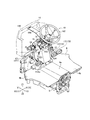
- FIG. 1 is a left side view of a traveling vehicle according to the embodiment.
- FIG. 2 is a perspective view of the control device according to the embodiment as viewed from the upper left rear side.
- FIG. 3 is a rear view of the control device according to the embodiment.
- FIG. 4 is a rear view of the control device according to the embodiment.
- FIG. 5 is a left side view of the control device according to the embodiment.
- FIG. 6 is a left side view of the control device according to the embodiment.
- FIG. 7 is an enlarged view of the shuttle lever and the guide plate according to the embodiment.
- FIG. 8 is an enlarged view of the guide plate according to the embodiment.
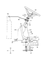
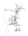
- FIG. 9 is an enlarged view of the steering unit according to the embodiment.
- FIG. 10 is a sectional view taken along line BB of FIG.
- FIG. 11 of the case according to the embodiment is a cross-sectional view taken along the line AA of FIG. 10 of the case according to the exemplary embodiment.
- FIG. 12 is a cross-sectional view taken along line CC of FIG. 10 of the case according to the embodiment.
- FIG. 13 is a cross-sectional view taken along line DD of FIG. 10 of the case according to the embodiment.
- FIG. 14 is a perspective view for explaining the bearing according to the embodiment.
- FIG. 15 is a diagram for explaining the movement of the transmission unit.
- FIG. 16 is a diagram for explaining the movement of the transmission unit.
- FIG. 1 is a side view of a traveling vehicle according to the embodiment.
- FIG. 2 is a perspective view of the control device according to the embodiment as viewed from the upper left rear side. In this embodiment, a tractor is illustrated as the traveling vehicle 1.
- the arrow X shown in the drawing indicates the width direction of the traveling vehicle 1
- the arrow Y indicates the front-back direction of the traveling vehicle 1
- the arrow Z indicates the up-down direction of the traveling vehicle 1.
- the arrow X1 indicates the right direction of the traveling vehicle 1
- the arrow X2 indicates the left direction of the traveling vehicle 1.
- the arrow Y1 indicates the front direction (forward direction) of the traveling vehicle 1
- the arrow Y2 indicates the rear direction (reverse direction) of the traveling vehicle 1.
- the arrow Z1 indicates the upward direction of the traveling vehicle 1
- the arrow Z2 indicates the downward direction of the traveling vehicle 1.
- a direction from the center in the width direction X of the traveling vehicle 1 to the right side or the left side is referred to as an outer direction, and a direction from the right side or the left side of the traveling vehicle 1 in the width direction X to the center is referred to as an inward direction. Therefore, the center in the width direction X of the traveling vehicle 1 may be referred to as “vehicle inside”, and the right side and the left side of the center in the width direction X may be referred to as “vehicle outside”.
- the traveling vehicle 1 has a vehicle body 2 that can travel.
- the vehicle body 2 includes an engine 3, a case 5, a case cover member 6, and a control device 10.
- the engine 3 is a diesel engine.
- the engine 3 is located at the front of the traveling vehicle 1 and is covered with a hood.
- the engine 3 may be an electric motor, or may be a hybrid type having a diesel engine and an electric motor.
- the case 5 has a flywheel housing, a clutch housing, and a mission case.
- the flywheel housing is connected to the rear part of the engine 3 and houses the flywheel.
- the clutch housing is connected to the rear part of the flywheel housing and houses a clutch that intermittently transmits the power of the engine 3 transmitted via the flywheel.
- the mission case is connected to the rear part of the clutch housing.
- the case 5 houses a power transmission device that transmits the power from the engine 3.
- the power transmission device may include a forward/reverse switching device 20 and a transmission device 30.
- the case 5 accommodates the forward/reverse switching device 20 that switches the traveling vehicle between forward and reverse, and the transmission 30 that shifts the power from the engine 3 and transmits the power to the drive wheels.
- the forward/reverse switching device 20 has a forward gear 25 and a reverse gear 26 as gears.
- the case 5 is arranged below the control device 10 in the vertical direction Z.
- the case cover member 6 covers the upper part of the case 5.
- the case cover member 6 has a main body portion 6a that overlaps with an upper portion of the case 5 and a side portion 6b that is arranged outside the main body portion 6a in the width direction X when the vehicle is viewed from above.
- the upper surface of the main body portion 6a is located higher than the upper surface of the side portion 6b (see FIGS. 2-4).
- the driver's foot is placed on the case cover member 6.
- the case cover member 6 is arranged on the front side in the front-rear direction Y with respect to the driver's seat 9. It is arranged on the rear side in the front-rear direction Y with respect to the control base 12.
- the traveling vehicle 1 has a traveling device 8 that supports the vehicle body 2 so that the vehicle body 2 can travel.
- the traveling device 8 is a wheel-type traveling device having a plurality of front wheels 8A provided at a front portion of the vehicle body 2 and a plurality of rear wheels 8B provided at a rear portion of the vehicle body 2.
- the plurality of front wheels 8A include a left front wheel supported on the left side of the front axle case supported in front of the engine 3 and a right front wheel supported on the right side of the front axle case.
- the plurality of rear wheels 8B include a left rear wheel supported on the left side of the case 5 (a mission case or the like) and a right rear wheel supported on the right side of the case 5.
- the traveling device 8 may be a semi-crawler type traveling device (a traveling device having a front wheel 8A and a crawler type traveling mechanism adopted instead of the rear wheel 8B).
- the front wheel 8A is a steering wheel that can be steered by moving a cylinder rod of a steering cylinder provided in the front portion of the front axle case. By manipulating the front wheels 8A, the direction of the vehicle body 2 can be changed (the vehicle body can be steered).
- the steering cylinder is composed of a hydraulic cylinder.
- the front wheels 8A and the rear wheels 8B at least the rear wheels 8B are drive wheels, and the power output from the transmission 30 is transmitted to the drive wheels.
- a driver's seat 9 on which a driver sits is mounted on the rear portion of the vehicle body 2. In front of the driver's seat 9, there is provided a control device 10 partially covered by a control cover 11.
- FIGS. 3 to 11. 3 and 4 are rear views of the control device according to the embodiment. However, in FIG. 4, some members (the case cover member 6, the pedal 17, the support pipe 18, the cover member 124, etc.) are omitted from FIG. 5 and 6 are left side views of the control device according to the embodiment. 6, some members (the case cover member 6, the pedal 17, the support pipe 18, the cover member 124, etc.) are omitted from FIG.
- FIG. 7 is an enlarged view of the shuttle lever and the guide plate according to the embodiment.
- FIG. 8 is an enlarged view of the guide plate according to the embodiment.
- FIG. 10 is a sectional view taken along line BB of FIG. 11 of the case according to the embodiment.
- 11 is a cross-sectional view taken along the line AA of FIG. 10 of the case according to the exemplary embodiment.
- FIG. 12 is a cross-sectional view taken along line CC of FIG. 10 of the case according to the embodiment.
- FIG. 13 is a cross-sectional view taken along line DD of FIG. 10 of the case according to the embodiment.
- FIG. 14 is a perspective view for explaining the bearing according to the embodiment.
- FIG. 15 is a diagram for explaining the movement of the transmission unit.
- FIG. 16 is a diagram for explaining the movement of the transmission unit. It should be noted that in each drawing, members may be omitted as appropriate.
- the control device 10 includes a control base 12, a shuttle lever 13, a guide plate 14, a transmission unit 15, a steering unit 16, a pedal 17, and a support pipe 18.
- the control base 12 includes a fixed bracket 122 and a cover member 124.
- the fixed bracket 122 is erected on the vehicle body 2 (case 5).
- the transmission portion 15 and the steering portion 16 are supported by the fixed bracket 122.
- the fixing bracket 122 has a first side wall 1221 and a second side wall 1222 facing the first side wall.
- the first side wall 1221 and the second side wall 1222 are arranged outside the transmission portion 15 in the width direction X.
- the first side wall 1221 and the second side wall 1222 are plate-shaped members extending in the vertical direction Z.
- the first side wall 1221 and the second side wall 1222 are arranged side by side in the width direction X (opposed in the width direction X).
- the first side wall 1221 is arranged on the left side of the center of the vehicle body 2 in the width direction X
- the second side wall 1222 is arranged on the right side of the center of the vehicle body 2 in the vehicle width direction.
- the first side wall 1221 and the second side wall 1222 are connected by a first connecting member 1223 and a second connecting member 1224.
- the left end of the first connecting member 1223 is fixed to the first side wall 1221 and the right end of the first connecting member 1223 is fixed (connected) to the second side wall 1222.
- the first connecting member 1223 has a through hole 1223a through which the steering post 164 penetrates, and the steering controller 166 is fixed.
- the left end of the second connecting member 1224 is fixed to the first side wall 1221 and the right end of the second connecting member 1224 is fixed (connected) to the second side wall 1222.
- the second connecting member 1224 fixes the first side wall 1221 and the second side wall 1222 at the front portions of the first side wall 1221 and the second side wall 1222, respectively.
- the fixed bracket 122 has a third side wall 1225 that supports the oil tank 168.
- the third side wall 1225 is fixed to the upper part of the second side wall 1222.
- the fixed bracket 122 has a fixed plate 1226.
- a through hole is formed in the fixed plate 1226.
- the transmission part 15 (specifically, the shuttle shaft 152 and the support cylinder 153) is inserted into the through hole.
- the fixed plate 1226 is fixed to the first side wall 1221.
- the cover member 124 covers the rear side of the steering controller 166.
- the cover member 124 is connected to the first side wall 1221 and the second side wall 1222.
- the shuttle lever 13 is a member that performs an operation for switching the traveling direction of the vehicle body 2.
- the operation of the shuttle lever 13 is transmitted to the forward/reverse switching device 20 via the transmission portion 15.
- the traveling direction (traveling direction) of the vehicle body 2 is switched to the forward traveling direction or the backward traveling direction.
- the shuttle lever 13 has a lever body 131 and a grip 132 connected to an upper end portion 131 a of the lever body 131.
- the guide plate 14 guides the shuttle lever 13.
- the guide plate 14 is a single plate-shaped member.
- the guide plate 14 has a rectangular shape in a top view (see FIG. 8).
- the guide plate 14 extends in the width direction X.
- the guide plate 14 has a guide hole 142 and an insertion hole 144.
- the guide hole 142 is a hole into which the shuttle lever 13 (the lower end portion 131b of the lever body 131) is inserted, and is a through hole that penetrates the guide plate 14.
- the guide hole 142 has an arcuate arc portion 142A and a protrusion 142B protruding in the width direction X from the center of the arc portion 142A in the front-rear direction Y when viewed from above.
- the insertion hole 144 is a through hole into which the transmission portion 15 is inserted and which penetrates the guide plate 14.
- the transmission portion 15 can be fixed by inserting the transmission portion 15 into the insertion hole 144.
- the insertion hole 144 is located inside the guide hole 142 in the width direction X.
- the guide plate 14 extends from the inside in the width direction X to the outside.
- the end portion 141 of the guide plate 14 in the width direction X is located outside the first side wall 1221 in the width direction X.
- the guide plate 14 is supported by the support member 145.
- the guide plate 14 is fixed to the support member 145.
- the position of the guide plate 14 is not fixed via the side wall (for example, the first side wall 1221) that constitutes the control device 10. Therefore, the position of the guide plate 14 can be freely designed without being affected by the position of the first side wall 1221.
- the support member 145 extends from the support body 146 to the control device 10. Therefore, the guide plate 14 is not fixed via the side wall (for example, the first side wall 1221) forming the control device 10. Therefore, the guide plate 14 is not composed of a member that is fixed to the first side wall 1221 and extends in the vertical direction Z. Therefore, the position of the guide plate 14 can be freely designed without being affected by the position of the first side wall 1221.
- the guide plate when an existing guide plate is fixed to the first side wall 1221, the guide plate is usually a first portion extending upward in the vertical direction Z from the first side wall 1221 and a width from an upper end of the first portion. And a second portion extending inward in the direction X. Therefore, in order to secure the length of the second portion that guides the shuttle lever, the length in the width direction X from the first side wall 1221 to the second side wall 1222 cannot be reduced more than necessary.
- the guide plate 14 according to the present embodiment since the guide plate 14 according to the present embodiment is not fixed to the first side wall 1221, it can be extended to the outside in the width direction X with respect to the first side wall 1221. Therefore, even if the length in the width direction X from the first side wall 1221 to the second side wall 1222 is reduced in order to widen the space under the driver's feet, the length in the width direction X of the guide plate 14 should be ensured. You can As a result, the space under the driver's feet can be increased without affecting the operation of the shuttle lever 13.
- the support member 145 is fixed to a support body 146 located on the front side of the control device 10 in the front-rear direction Y.
- the support 146 is arranged in the bonnet.
- the support body 146 is not fixed to the case 5.
- the support member 145 includes a first support member 145A to which the guide plate 14 is directly fixed, and a second support member 145B that supports the guide plate 14 via the first support member 145A.
- the first support member 145A is a plate-shaped member. On the rear side in the front-rear direction Y, the first support member 145A has an arc-shaped first end 145Ae1 along the steering post 164 and a second end 145Ae2 extending from the first end 145Ae1 in the rear direction Y2. (See Figure 8). The first support member 145A may be in contact with the steering post 164. In the first support member 145A, the left side portion 145AL is longer in the front-rear direction Y than the right side portion 145AR.
- the right side portion 145AR (second end portion 145Ae2) contacts the steering post 164, and thus the guide plate 14 moves. Can be suppressed. Therefore, the guide plate 14 can be firmly fixed. Further, the outer end of the right side portion 145AR in the width direction X extends rearward in the front-rear direction Y. As a result, even if a force in the left direction X2 is applied to the guide plate 14, the right side portion 145AR hits the steering post 164, so that the guide plate 14 can be prevented from moving.
- the guide plate 14 is fixed to the first support member 145A inside the width direction X. Specifically, the first support member 145A is fixed to the guide plate 14 on the outer side in the width direction X with bolts and nuts. Therefore, the guide plate 14 is fixed above the left side portion 145AL of the first support member 145A.
- the first support member 145A is fixed to the second support member 145B by a bolt and a nut at the front portion of the first support member 145A.
- the second support member 145B is a member extending in the front-rear direction Y.
- the second support member 145B is fixed to the first support member 145A with a bolt and a nut at the rear portion of the second support member 145B.
- the second support member 145B is fixed to the support body 146 with a bolt and a nut at the front portion of the second support member 145B.
- the transmission unit 15 is a member that transmits the operation of the shuttle lever 13 to the forward/reverse switching device 20.
- the transmission portion 15 is located on the front side of the cover member 124. As a result, it is possible to further increase the space under the driver's feet.
- the transmission unit 15 has a mounting member 151, a shuttle shaft 152, a support cylinder 153, an interlocking rod 154, a connecting member 155, a shuttle arm 156, and an engaging portion 157.
- the attachment member 151 is a member attached to the shuttle lever 13. Specifically, the lever body 131 is fixed to the left end portion of the mounting member 151. Specifically, the lever body 131 is fixed to the left end portion of the mounting member 151.
- the mounting member 151 is supported on the shuttle shaft 152 by bolts and nuts. The mounting member 151 (that is, the shuttle lever 13) can swing in the up-down direction Z about the bolt.
- the shuttle shaft 152 can be rotated about the axis by the shuttle lever 13.
- the upper portion 152A of the shuttle shaft 152 projects upward from the support cylinder 153.
- the upper portion 152A is inserted into the insertion hole 144.
- the upper portion 152A is attached to the mounting member 151 and supports the mounting member 151.
- a lower portion 152B of the shuttle shaft 152 projects downward from the support cylinder 153.
- the lower portion 152B is bent in the width direction X.
- the end portion of the lower portion 152B is connected to the interlocking rod 154.
- the support cylinder 153 is arranged vertically so as to extend in the vertical direction Z.
- the support cylinder 153 is located between the first side wall 1221 and the second side wall 1222 in the width direction X.
- the support cylinder 153 is located between the second connecting member 1224 and the cover member 124 in the front-rear direction Y.
- the support cylinder 153 is inserted into a through hole formed in the fixed plate 1226 and fixed via the fixed plate 1226. Therefore, the support cylinder 153 is fixed to the fixed bracket 122.
- the interlocking rod 154 is a member extending in the front-rear direction Y.
- the front end portion 154A of the interlocking rod 154 is connected to the shuttle shaft 152 by a bolt and a nut.
- the rear end portion 154B of the interlocking rod 154 is connected to the connecting member 155 by a bolt and a nut. Therefore, the interlocking rod 154 is connected to the shuttle arm 156 via the connecting member 155.
- the connecting member 155 connects the interlocking rod 154 and the shuttle arm 156.
- the inner end of the connecting member 155 is connected to the interlocking rod 154 with a bolt and a nut.
- the outer end of the connecting member 155 is directly fixed to the shuttle arm 156.
- the shuttle arm 156 extends in the vertical direction Z.
- the shuttle arm 156 has an arm body 156A and an arm cylinder 156B.
- the upper end of the arm body 156A is fixed to the connecting member 155.
- the arm body 156A also rotates as the connecting member 155 rotates.
- the lower end of the arm body 156A is fixed to the engaging portion 157.
- the arm body 156A is inserted into the arm cylinder 156B.
- the arm cylinder 156B is not connected to the connecting member 155 but is connected to the case 5.
- the engagement portion 157 is a member that comes into contact with the shift fork 21.
- the engaging portion 157 is fixed to the arm body 156A.
- the shift fork 21 moves according to the movement of the engaging portion 157.
- the engaging portion 157 is fixed to the arm body 156A inside the width direction X, and engages with the shift fork 21 (third fork portion 213) outside the width direction X.
- the steering unit 16 has a steering handle 162, a steering post 164, a steering controller 166, and an oil tank 168.
- the steering handle 162 is a member operated by the driver.
- the steering handle 162 is a member that operates the steering of the vehicle body 2, and is manually operated by the driver.
- the steering post 164 supports the steering handle 162 and the steering controller 166.
- a steering shaft (shaft) is inserted into the steering post 164.
- the steering post 164 transmits the operation by the steering handle 162 to the steering controller 166 via the steering shaft.
- the steering controller 166 controls the steering of the traveling vehicle 1 by operating the steering handle 162.
- the steering controller 166 is hydraulic.
- the steering controller 166 is a valve that controls the steering cylinder.
- the steering controller 166 is a rotary valve that is operated by the steering handle 162 to control the flow rate of the hydraulic oil and switch the direction of the hydraulic oil.
- the steering controller 166 is a valve that can output hydraulic oil that transmits the steering of the steering handle 162.
- the steering controller 166 outputs hydraulic oil corresponding to the operation amount of the steering handle 162 from a port corresponding to the operation direction.
- the hydraulic oil output from the steering controller 166 is sent to the steering cylinder to move the cylinder rod of the steering cylinder. As a result, the left front wheel and the right front wheel are steered according to the rotating operation of the steering handle 162.
- a plurality of hydraulic hoses (first hose H1 to fourth hose H4) are connected to the steering controller 166.
- the first hose H1 is a hydraulic hose that supplies the hydraulic oil discharged from the hydraulic pump P mounted on the traveling vehicle 1 to the steering controller 166.
- the hydraulic pump P is provided in the bonnet. The hydraulic pump P is driven by the power of the engine 3.
- the second hose H2 is a hydraulic hose that supplies (discharges) hydraulic oil to the case 5 that stores hydraulic oil (mission oil).
- the second hose H2 has a first hose portion H2A from the steering controller 166 to the oil tank 168 and a second hose portion H2B from the oil tank 168 to the case 5.
- the second hose H2 corresponds to a flow path that connects the steering controller 166 and the tank port T.
- the hydraulic oil flows through the second hose H2.
- the tank port T is the case 5. More specifically, the tank port T is a first storage chamber 51 (and a second storage chamber 52) described later.
- the oil tank 168 is arranged in the middle of the second hose H2. Hydraulic oil is stored in the oil tank 168 while the engine 3 of the traveling vehicle 1 is stopped. The oil tank 168 stores hydraulic oil even when the engine 3 is operating. The oil tank 168 is arranged below the steering handle 162. Thereby, the length of the flow path of the second hose portion H2B can be shortened.
- the oil tank 168 has an inflow port 168A and an outflow port 168B.
- the inlet 168A is an inlet through which the hydraulic oil flows into the oil tank 168.
- the outlet 168B is an outlet through which the hydraulic oil flows from the oil tank 168.
- the outflow port 168B is arranged at a position higher than the inflow port 168A.
- the outflow port 168B may be arranged inside the oil tank 168.
- the outlet 168B may be arranged inside the oil tank 168 with a tubular portion 1682 having the outlet 168B. In this case, the upper end of the tubular portion 1682 corresponds to the outlet 168B.
- the tubular portion 1682 extends from the lower surface 168L of the oil tank 168 toward the upper surface 168U. When the working oil stored in the oil tank 168 exceeds the height of the outlet 168B, it flows into the second hose H2 from the outlet 168B by gravity.
- the oil tank 168 has a space 168s in which hydraulic oil is stored.
- the lower surface 168L of the space 168s is arranged at a position higher than the inflow port H2Ain through which the hydraulic oil flows from the steering controller 166 to the flow path (second hose H2).
- the steering controller 166 can maintain the hydraulic pressure.
- the third hose H3 and the fourth hose H4 are connected to the steering cylinder.
- the third hose H3 is a hydraulic hose for turning left.
- the steering oil operates so as to steer the left front wheel and the right front wheel to the left by the hydraulic oil supplied through the third hose H3.
- the fourth hose H4 is a hydraulic hose for turning right.
- the steering cylinder operates so as to steer the left front wheel and the right front wheel to the left by the operating oil supplied through the fourth hose H4.
- the pedal 17 is operated under the driver's feet. As shown in FIGS. 2, 3, and 5, the pedal 17 is arranged outside the control base 12 in the width direction X.
- the pedal 17 has a clutch pedal 171, a first brake pedal 172, and a second brake pedal 173.
- the clutch pedal 171 is a pedal for operating the clutch.
- the clutch pedal 171 has a pedal plate portion 171a and a pedal body 171b. One end of the pedal plate portion 171a is connected to the support pipe 18. The other end of the pedal plate portion 171a is connected to the pedal body 171b.
- the pedal body 171b is a portion that is stepped on the sole of the driver when the driver operates it.
- the first brake pedal 172 and the second brake pedal 173 are pedals that operate a brake that brakes the traveling device 8.
- the first brake pedal 172 has a pedal plate portion 172a and a pedal body 172b. One end of the pedal plate portion 172a is connected to the support pipe 18. The other end of the pedal plate portion 172a is connected to the pedal body 172b.
- the second brake pedal 173 has the same configuration as the first brake pedal 172.
- the pedal body 172b is a portion that is stepped on the sole of the driver when the driver operates it.
- the clutch pedal 171 is arranged on the left side of the control platform 12.
- the first brake pedal 172 and the second brake pedal 173 are arranged on the right side of the operation platform 12.
- the second brake pedal 173 is arranged on the right side of the first brake pedal 172.
- the support pipe 18 is a pipe that supports the pedal 17.
- the support pipe 18 is fixed (connected) to the control stand 12.
- the support pipe 18 is a pipe extending in the width direction X.
- the case 5 includes a first storage chamber 51 in which the forward/reverse switching device 20 is stored, a second storage chamber 52 in which the transmission 30 is stored, and a first storage chamber in which the clutch is stored. And 3 storage chambers 53.
- the first storage chamber 51 is arranged between the second storage chamber 52 and the third storage chamber 53 in the front-rear direction Y.
- the first storage chamber 51 is arranged below the control device 10. Therefore, the forward/reverse switching device 20 is arranged below the control device 10.
- the case 5 has a case upper part 51A, a case lower part 51B, a case left part 51C, a case right part 51D, a first case wall part 55, and a second case wall part 56.
- the case upper portion 51A is located above the first storage chamber 51. Therefore, the case upper portion 51A is a portion disposed above the space forming the first storage chamber 51.
- the case lower portion 51B is located below the first storage chamber 51.
- the case left portion 51C is located on the left side of the first storage chamber 51.
- the case right portion 51D is located on the right side of the first storage chamber 51.
- the case 5 has a through hole 51Aa which penetrates the case upper portion 51A and in which the transmission portion 15 is inserted. Specifically, the arm body 156A is inserted into the through hole 51Aa. Compared to the case where the transmission unit 15 is inserted from the side surface of the case 5, it is not necessary to bring the transmission unit 15 to the side surface of the case 5. Therefore, the space under the foot can be widened. In addition, it is not necessary to provide a long cover in the width direction X below the driver's feet to cover the transmission unit 15. Therefore, the space under the driver's feet can be expanded. Further, since the distance of the transmission portion 15 from the shuttle lever 13 to the forward/reverse switching device 20 can be shortened, the shift feeling can be improved. Since the rigidity of the transmission portion 15 is not increased to improve the shift feeling, but the length of the transmission portion 15 is shortened to improve the shift feeling, the cost can be reduced.
- the pedal 17 (for example, the clutch pedal 171) is arranged at a position closer to the driver's seat 9 than the through hole 51Aa in the front-rear direction Y.
- the rear end of the pedal body 171b is arranged at a position closer to the through hole 51Aa in the front-rear direction Y.
- the rear end of the pedal body 171b is arranged in the front-rear direction Y at a position closer to the transmission portion 15 itself in the front-rear direction Y.
- the pedal 17 may be arranged at a position closer to the driver's seat than the through hole 51Aa and the transmission section 15 in a state where the driver is not operating (normal state).
- the through hole 51Aa and the transmission portion 15 may be arranged closer to the driver's seat than the pedal 17.
- the front end of the case cover member 6 in the front-rear direction Y may be located on the rear side of the through-hole 51Aa (and the transmission portion 15) in the front-rear direction Y. More specifically, the front end of the body portion 6a of the case cover member 6 may be located behind the through hole 51Aa (and the transmission portion 15) in the front-rear direction Y. Therefore, it can be seen that the case cover member 6 does not cover the transmission portion 15. Between the case 5 and the case cover member 6, it is not necessary to dispose the transmission part 15 in order to extend the transmission part 15 to the side surface of the case 5.
- the case cover member in the vertical direction Z, the case cover member can be arranged closer to the case 5 (that is, on the lower side), so that the space under the driver's feet can be increased.
- the front end of the side portion 6b of the case cover member 6 may or may not be located behind the through hole 51Aa (and the transmission portion 15) in the front-rear direction Y.
- the through hole 51Aa and the transmission portion 15 may be located inside the first side wall 1221 and the second side wall 1222 in the width direction X. This can prevent the driver's foot from hitting the transmission unit 15. Further, the transmission portion 15 may be located inside the side portion 6b of the case cover member 6 in the width direction X. The transmission part 15 may be located inside the width direction X rather than the outer end part of the main body part 6a of the case cover member 6 in the width direction X.
- the pedal 17 (for example, the clutch pedal 171) may be located inside the main body portion 6a of the case cover member 6 in the width direction X. With such a configuration, a distance in the width direction X between the pedal 17 (for example, the clutch pedal 171) and the transmission portion 15 can be secured.
- the first case wall 55 is located between the first storage chamber 51 and the second storage chamber 52.
- the first case wall portion 55 separates the first storage chamber 51 and the second storage chamber 52.
- the second case wall portion 56 is located between the first storage chamber 51 and the third storage chamber 53.
- the second case wall portion 56 separates the first storage chamber 51 and the third storage chamber 53.
- the forward/reverse switching device 20 is housed in the first housing chamber 51.
- the forward/reverse switching device 20 includes a shift fork 21, a main shaft 22, a shifter 23, a fork rod 24, a forward gear 25, a reverse gear 26, a coupling 27, and a synchronizer ring 28.
- the shift fork 21 can be moved via the transmission unit 15 by operating the shuttle lever.
- the shift fork 21 is attached to the fork rod 24.
- the shift fork 21 has a pair of first fork parts 211 (211U, 211L), a second fork part 212, and a third fork part 213.
- the first fork portion 211 is connected to the shifter 23. As a result, the shift fork 21 (first fork portion 211) moves and the shifter 23 also moves.
- the pair of first fork parts 211 has an upper fork part 211U arranged on the upper side and a lower fork part 211L arranged on the lower side.
- the pair of first fork portions 211 extends from the second fork portion 212.
- the upper fork portion 211U extends upward from the second fork portion 212.
- the lower fork portion 211L extends inward in the width direction X from the second fork portion 212.
- the second fork portion 212 exists between the pair of first fork portions 211.
- the second fork portion 212 has a through hole into which the fork rod 24 is inserted.
- the third fork part 213 is engaged with the transmission part 15.
- the third fork portion 213 is connected to the upper fork portion 211U of the pair of first fork portions 211. Specifically, the third fork portion 213 is connected to the upper end portion of the upper fork portion 211U. Accordingly, the third fork portion 213 engaged with the transmission portion 15 is arranged on the upper side, so that the length of the transmission portion 15 can be shortened. As a result, it is possible to suppress deterioration of the shift feeling.
- a shifter 23, a forward gear 25, a reverse gear 26, a coupling 27, and a synchronizer ring 28 are attached to the main shaft 22. That is, the forward gear 25, the reverse gear 26, the coupling 27, and the synchronizer ring 28 are inserted in the main shaft 22.
- the central axis (rotating shaft) 22c of the main shaft 22 is closer to the case upper portion 51A than the case lower portion 51B. As a result, the distance from the transmission portion 15 inserted in the case 5 to the forward/reverse switching device 20 can be shortened.
- the synchronizer ring 28 is for synchronizing the rotation of gears.
- the synchronizer ring 28 has a first synchronizer ring 281 that comes into contact with the forward gear 25 and a second synchronizer ring 282 that comes into contact with the reverse gear 26.
- the shifter 23 and the coupling 27 are arranged between the first synchronizer ring 281 and the second synchronizer ring 282.
- the shifter 23 is movable along the main shaft 22 between the forward gear 25 and the reverse gear 26.
- the shifter 23 changes the connection (meshing) between the forward gear 25 and the reverse gear 26.
- a coupling 27 is arranged inside the shifter 23 in the radial direction.
- the shifter 23 starts to move in one direction (for example, the forward direction Y1)
- the coupling 27 presses the first synchronizer ring 281 against the forward gear 25.
- Due to the frictional force generated in the forward gear 25, the rotation of the coupling 27 rotating integrally with the main shaft 22 starts to be transmitted to the synchronizer ring 28 and the forward gear 25.
- the forward gear 25 meshes with a gear mounted on a shaft different from the main shaft 22.
- the drive wheels are designed to rotate so that the traveling vehicle 1 moves forward as the shaft rotates due to the rotation of the gear.
- the coupling 27 presses the second synchronizer ring 282 against the reverse gear 26. Due to the frictional force generated in the reverse gear 26, the rotation of the coupling 27 starts to be transmitted to the synchronizer ring 28 and the reverse gear 26. It meshes with a back gear attached to a shaft different from the main shaft 22. The rotation of the back gear causes the shaft to rotate, whereby the drive wheels are designed to rotate so that the traveling vehicle 1 moves backward.
- the synchronizer ring 28 may be pressed toward the forward gear 25 or the reverse gear 26 by a synchronizer key arranged between the coupling 27 and the shifter 23.
- the transmission 30 has a main transmission section and an auxiliary transmission section.
- the main transmission unit changes (outputs) rotation input from the propulsion shaft.
- the sub-transmission unit changes the rotation input from the main transmission unit and outputs (changes) the rotation.
- the traveling vehicle 1 has a supply pipe 60 that supplies oil (operating oil) from the outside of the case 5 to the inside of the case 5.
- the supply pipe 60 is arranged in the accommodation space (first accommodation chamber 51) of the case 5.
- the supply pipe 60 supplies oil to the first storage chamber 51.
- the supply pipe 60 is a pipe through which the oil flowing through the second hose H2 passes. More specifically, the oil flowing through the second hose portion H2B flows through the supply pipe 60. Oil (hydraulic oil) discharged from the hydraulic device (specifically, the steering controller 166) is supplied (discharged) to the inside of the case 5.
- the supply pipe 60 has a main body portion 62, a discharge port 64, and a guide portion 66.
- the main body portion 62 is a tubular member through which oil flows.
- the body 62 may be a circular tube.
- the main body portion 62 extends parallel to the central axis (rotational axis) 22c of the main shaft 22. Therefore, the main body 62 extends from the first case wall 55 along the front-rear direction Y (front direction Y1). As shown in FIG. 10, therefore, the main body portion 62 extends so as not to overlap the central axis 22c of the main shaft 22 in the vertical direction Z.
- the body portion 62 is arranged closer to the second hose H2 than the central axis 22c of the main shaft 22 is. The distance from the second hose H2 to the supply pipe 60 is shortened, and oil can be quickly applied to the gear.
- the oil is discharged from the discharge port 64.
- the outlet 64 may be provided in the guide portion 66.
- the discharge port 64 is arranged above the main shaft 22.
- the guide portion 66 guides the oil discharged from the discharge port 64 between the gear and the synchronizer ring 28. As a result, oil is applied to the contact surface of the synchronizer ring 28 that contacts the gear. Therefore, even when the synchronizer ring 28 is not immersed in oil, the lubrication between the gear and the synchronizer ring 28 can be maintained, and the wear of the synchronizer ring 28 can be suppressed.
- the guide portion 66 may be cylindrical.
- the guide portion 66 may be a nozzle.
- the guide portion 66 extends from the main body portion 62 toward between the gear and the synchronizer ring 28.
- a discharge port 64 is provided at the end of the guide portion 66 in the extending direction.
- the extending direction of the guide portion 66 (the vertical direction Z in FIG. 12) is orthogonal to the extending direction of the main body portion 62 (the front-back direction Y in FIG. 12). Therefore, the guide portion 66 extends so as to be orthogonal to the central axis 22c of the main shaft 22.
- the center of the discharge port 64 and the central axis 22c of the main shaft 22 are arranged.
- the extending direction of the guide portion 66 is inclined with respect to the vertical direction Z such that the angle formed by the imaginary line passing through and the extending direction of the guide portion 66 is less than 30 degrees. Accordingly, when the main body portion 62 and the central axis 22c of the main shaft 22 do not overlap in the vertical direction Z, oil can be discharged toward the axis of the gear (that is, the central axis of the main shaft 22). Therefore, it becomes easier for the oil to reach not only the radially outer contact surface between the gear and the synchronizer ring 28 but also the radially inner contact surface between the gear and the synchronizer ring 28. It becomes easier to lubricate the contact surface between the gear and the synchronizer ring 28. Note that, in FIG.
- the guide portion 66 may extend upward from the axis of the gear or downward from the axis of the gear in consideration of how oil is applied. ..
- the discharge port 64 be arranged near the synchronizer ring 28 (and gear).
- the distance from the outlet 64 to the synchronizer ring 28 is preferably shorter than the distance from the synchronizer ring 28 to the central axis 22c of the main shaft 22.
- the guide portion 66 may be kept away from the synchronizer ring 28 (and gear) to the extent that the supply pipe 60 does not hit the synchronizer ring 28 (or gear) due to the shaking of the supply pipe 60 caused by the driving of the traveling vehicle 1. preferable.
- the guide section 66 has a first guide section 661 and a second guide section 662.
- the first guide portion 661 guides the oil between the forward gear 25 and the first synchronizer ring 281.
- the first guide portion 661 extends from the main body portion 62 toward the forward gear 25.
- a first discharge port 641 that faces the forward gear 25 and the first synchronizer ring 281 is provided at the end of the first guide portion 661 in the extending direction.
- the second guide portion 662 guides the oil between the reverse gear 26 and the second synchronizer ring 282.
- the second guide portion 662 extends from the main body portion 62 toward between the reverse gear 26 and the second synchronizer ring 282.
- a second discharge port 642 facing the reverse gear 26 and the second synchronizer ring 282 is provided at an end of the second guide portion 662 in the extending direction.
- the first guide portion 661 is arranged upstream of the downstream end portion of the supply pipe 60.
- the downstream end of the supply pipe 60 is sealed.
- the first guide portion 661 is arranged on the downstream side of the second guide portion 662.
- the first case wall portion 55 is provided with an opening 550 below the supply pipe 60 and penetrating the first storage chamber 51 and the second storage chamber 52.
- the opening 550 may include a first opening 551, a second opening 552, a third opening 553, and a fourth opening 554.
- the first opening 551 is arranged at the lowermost side than the other openings.
- the second opening 552 is arranged above the first opening 551.
- the third opening 553 is arranged above the second opening 552.
- the fourth opening 554 is arranged above the third opening 553. Further, as shown in FIG. 13, the fourth opening 554 is arranged above the synchronizer ring 28 (the upper end of the synchronizer ring 28).
- the traveling vehicle 1 has a shaft 70 and a bearing 58.
- the shaft 70 is arranged in the first storage chamber 51 and rotates by the power from the engine 3.
- a shaft 70 is inserted in the bearing 58.
- the bearing 58 is fixed to the first case wall 55 so as to close the opening 550.
- the shaft 70 has a first shaft 71, a second shaft 72, and the main shaft 22 described above.
- a gear is attached to each shaft.
- the bearing 58 includes a first bearing 581, a second bearing 582 (second bearing 582A, second bearing 582B), and a third bearing 583 (third bearing 583A, third bearing 583B).
- the first bearing 581 is fixed to the first case wall 55 so as to close the first opening 551.
- the second bearing 582 is fixed to the first case wall 55 so as to close the second opening 552
- the third bearing 583 is fixed at the first case wall so as to close the third opening 553. It is fixed to 55.
- the first shaft 71 is inserted into the first bearing 581
- the second shaft 72 is inserted into the second bearing 582
- the main shaft 22 is inserted into the third bearing 583.
- the bearing 58 is not fixed to the fourth opening 554.
- the bearing 58 has an inner ring 58I, an outer ring 58O, and a rolling element 58R.
- the shaft 70 is inserted inside the inner ring 58I.
- the rolling elements 58R are rollers or balls.
- the rolling element 58R is arranged between the inner ring 58I and the outer ring 58O.
- the bearing 58 may include a retainer that determines the position of the rolling element 58R.
- the second bearing 582A may include an inner ring 582I, an outer ring 582O, a rolling element 582R, and a seal portion 582S.
- the seal portion 582S closes between the inner ring 582I and the outer ring 582O.
- the seal portion 582S is arranged closer to the first storage chamber 51 than the rolling element 582R.
- the seal portion 582S is not arranged closer to the second storage chamber 52 than the rolling element 582R. Therefore, in the second bearing 582A, the seal portion 582S is arranged only on one side.
- the first bearing 581, the second bearing 582B, and the third bearing 583 do not have a seal portion.
- the oil level when the engine is stopped is S1
- the oil level when the engine is rotating is S2.
- the oil in the case 5 circulates between the hydraulic device (steering controller 166) and the case 5.
- the oil stored in the second storage chamber 52 is supplied to the hydraulic equipment.
- oil is supplied from the second storage chamber 52 to the hydraulic equipment.
- the oil in the second storage chamber 52 is slightly reduced, and the oil level of the oil in the second storage chamber 52 is slightly lowered. Since the capacity of the second storage chamber 52 in which the oil is stored is larger than the capacity of the first storage chamber 51, the difference in oil level fluctuation between the rotation and the stop of the engine 3 is small.
- the oil By supplying the oil from the second storage chamber 52 to the hydraulic equipment, the oil is supplied (discharged) from the hydraulic equipment to the first storage chamber 51.
- oil (operating oil) from the steering controller 166 is supplied to the first storage chamber 51 through the discharge port 64.
- the oil level rises to S2 while the engine 3 is rotating. While the oil is being supplied, the oil level of the oil in the first storage chamber 51 is higher than that before the oil was supplied. Further, the oil is preferentially accumulated in the first storage chamber 51.
- the synchronizer ring 28 attached to the main shaft 22 is easily immersed in the oil stored in the first storage chamber 51, so that the amount of oil used can be reduced. It can be reduced.
- the oil is supplied to the first storage chamber 51 by the supply pipe 60.
- the supply pipe 60 does not have the guide portion 66 and the body portion 62 is directly provided with the discharge port 64.
- the oil flowing through the main body portion 62 of the supply pipe 60 has a velocity component along the main body portion 62. Therefore, the oil discharged from the discharge port 64 of the main body portion 62 has a velocity component in the extending direction of the main body portion 62 (forward direction Y1 in FIG. 12), and thus is located in front of the discharge port 64 (left side in FIG. 12). ) Is discharged toward.
- the viscosity of the oil in the case 5 which has become high temperature due to the driving of the traveling vehicle 1 becomes lower than that of the oil having a low temperature.
- the speed of the oil flowing in the supply pipe 60 is increased, and the oil is discharged further to the front side.
- the upstream discharge port 64 has a higher pressure in the pipe than the downstream discharge port 64, so the oil velocity is high and the oil is discharged to the front side.
- Cheap even if the gear and the synchronizer ring 28 are arranged so that the oil discharge trajectory passes between the gear and the synchronizer ring 28, the discharge trajectory changes depending on whether the oil temperature is high or low.
- the oil may not be applied to the contact surface of the synchronizer ring 28.
- the synchronizer ring 28 attached to the main shaft 22 is not soaked in the oil until the oil level rises to S2, and thus is easily damaged. Even if the oil level rises to S2, only part of the synchronizer ring 28 is soaked in oil, so it is preferable to apply oil to the part not soaked in oil.
- the guide portion 66 guides the oil discharged from the discharge port 64 to the gear. Therefore, the oil supplied by the supply pipe 60 is guided between the gear and the synchronizer ring 28 by the guide portion 66, so that the oil is applied to the contact surface of the synchronizer ring 28 that contacts the gear. Therefore, even when the synchronizer ring 28 is not immersed in oil, the lubrication between the gear and the synchronizer ring 28 can be maintained, and the wear of the synchronizer ring 28 can be suppressed. Further, not only the synchronizer ring 28 but also the gear can be prevented from being worn.
- a discharge port 64 is provided at the end of the tubular guide portion 66 in the extending direction (the front-rear direction Y in FIGS. 11 and 12). Since the guide portion 66 extends toward the gear and the synchronizer ring 28, the oil flowing inside the tubular guide portion 66 is discharged toward the gap between the gear and the synchronizer ring 28. It This allows the oil to be accurately applied between the gear and the synchronizer ring 28.
- the gear to which the oil is guided by the guide portion 66 is the gear of the forward/reverse switching device 20.
- work for example, farming work
- switching between forward and reverse is frequently generated, so the number of shifts of the forward/reverse switching device 20 is larger than that of the transmission 30. , Increase. Therefore, the synchronizer ring 28 that comes into contact with the gear of the forward/reverse switching device 20 is more easily worn than the synchronizer ring 28 that comes into contact with the gear of the transmission 30. Therefore, by introducing oil between the gear of the forward/reverse switching device 20 and the synchronizer ring 28, it is possible to suppress wear of the synchronizer ring 28, which is easily worn.
- the guide portion 66 includes a first guide portion 661 that guides oil between the forward drive gear 25 and the first synchronizer ring 281, and a second guide portion that guides oil between the reverse drive gear 26 and the second synchronizer ring 282. 662 and. Since oil is applied to each of the first synchronizer ring 281 that contacts the forward gear 25 and the second synchronizer ring 282 that contacts the reverse gear 26, wear of both synchronizer rings 28 can be suppressed.
- the opening 550 is provided in the first case wall 55, the oil flows from the first storage chamber 51 to the second storage chamber 52 through the opening 550. As a result, when the engine 3 is rotating, the oil level in the second storage chamber 52 drops to S2, but the second storage chamber 52 does not run out of oil.
- the bearing 58 is fixed so as to close the opening 550, the flow rate of the oil flowing from the first storage chamber 51 to the second storage chamber 52 through the opening 550 is limited. As a result, even if the first case wall 55 is provided with the opening 550, it becomes easier to store the oil in the first storage chamber 51, and at least a part of the synchronizer ring 28 is easily immersed in the oil.
- the second bearing 582A has a seal portion 582S.
- the flow rate of oil flowing to 52 is further restricted. Therefore, the oil can be easily stored in the first storage chamber 51, and at least a part of the synchronizer ring 28 can be easily immersed in the oil.
- the traveling vehicle 1 is driven to reach a high temperature, the viscosity of the oil decreases, so that the oil easily flows from the first storage chamber 51 to the second storage chamber 52 through the opening 550. Therefore, by restricting the oil flow rate by the seal portion 582S, it is possible to maintain the oil level of the first storage chamber 51 high even when the oil temperature is high.
- the amount of oil supplied to the first storage chamber 51 is small, so the speed at which the oil level rises in the first storage chamber 51 becomes slow. Therefore, by limiting the flow rate of the oil flowing from the first storage chamber 51 to the second storage chamber 52 by the bearing 58, it is easy to store the oil in the first storage chamber 51 even when the engine speed is low. Become. As a result, at least a part of the synchronizer ring 28 is easily immersed in the oil.
- the oil is opened through the gap between the shaft 70 and the bearing 58 and the gap between the first case wall portion 55 and the bearing 58. It flows out from the first storage chamber 51 to the second storage chamber 52 through the portion 550. Further, when the seal portion 58S does not seal between the inner ring 58I and the outer ring 58O, the oil flows through the bearing 58 into the second storage chamber 52 although the flow rate is small.
- the seal portion 582S of the second bearing 582 is arranged toward the first storage chamber 51 rather than the rolling element 582R. Since the oil is stored on the first storage chamber 51 side with respect to the seal portion 582S, it is easier to store the oil in the first storage chamber 51 as compared with the case where the seal portion 582S is farther than the rolling elements 582R (the oil level is faster. It becomes easier to go up). Therefore, at least a part of the synchronizer ring 28 is easily immersed in the oil.
- the first opening 551 to which the first bearing 581 without the seal portion 58S is fixed is located below the second opening 552 to which the second bearing 582 having the seal portion 582S is fixed.
- oil for example, high-temperature oil
- a third bearing 583 having no seal portion 58S is fixed to the third opening 553.
- the third opening 553 is located above the second opening 552. Accordingly, in the third opening 553, oil is more likely to flow into the second storage chamber 52 than in the second opening 552. Therefore, it is possible to prevent the oil from being stored in the first storage chamber 51 more than necessary.
- the fourth opening 554 is arranged above the synchronizer ring 28.
- the fourth opening 554 is open without the bearing 58 being fixed.
- the oil stored above the synchronizer ring 28 is more likely to flow into the second storage chamber 52 as compared with the third opening 553.
- the oil stored above the synchronizer ring 28 does not contribute to the lubrication of the synchronizer ring 28, so that it is possible to further suppress the oil from being stored in the first storage chamber 51 more than necessary.
- the shuttle lever 13 can swing upward in the neutral position against the biasing force of the spring.
- the shuttle lever 13 moves from the protrusion 142B of the guide hole 142 to the arc portion 142A.
- the shuttle lever 13 can move within the arc portion 142A of the guide hole 142. Therefore, the shuttle lever 13 can swing back and forth.
- the shuttle lever 13 When the shuttle lever 13 is moved in the direction F1 (rearward direction Y2) along the arc portion 142A, the shuttle lever 13 is moved from the neutral position to the forward position.
- the forward/reverse switching device 20 When the shuttle lever 13 is in the forward position, the forward/reverse switching device 20 is in a state of transmitting forward power, and the traveling direction of the vehicle body 2 is switched to the forward direction.
- the shuttle lever 13 when the shuttle lever 13 is operated in the F1 direction, the upper portion 152A of the shuttle shaft 152 rotates in the F2 direction and the lower portion 152B of the shuttle shaft 152 moves in the F3 direction.
- the interlocking rod 154 moves in the F4 direction (rearward direction Y2), and the connecting member 155 and the shuttle arm 156 rotate in the F5 direction and the F6 direction, respectively.
- the engagement portion 157 moves in the F7 direction
- the shift fork 21 moves in the F8 direction (front direction Y1) along the main shaft 22.
- the shifter 23 is connected to the forward gear 25, and the forward/reverse switching device 20 switches to a state in which forward power is transmitted.
- the shuttle lever 13 when the shuttle lever 13 is operated in the R1 direction, the upper portion 152A of the shuttle shaft 152 rotates in the R2 direction and the lower portion 152B of the shuttle shaft 152 moves in the R3 direction.
- the interlocking rod 154 moves in the R4 direction (rearward direction Y2), and the connecting member 155 and the shuttle arm 156 rotate in the R5 direction and the R6 direction, respectively.
- the engaging portion 157 moves in the R7 direction
- the shift fork 21 moves in the R8 direction (rearward Y2) along the main shaft 22.
- the shifter 23 is connected to the reverse gear 26, and the forward/reverse switching device 20 is switched to a state of transmitting reverse power.
- the guide portion 66 may be provided by bending the downstream end of the supply pipe 60 to the gear side. As a result, the number of processing steps of the supply pipe 60 can be reduced as compared with the case where the first guide portion 661 and the first discharge port 641 are formed.
- the guide portion 66 may extend vertically downward from the main body portion 62. Since the oil is discharged vertically downward by the guide portion 66, it is difficult for the discharged oil to have a horizontal velocity component. Therefore, the discharged oil can easily reach the gear facing the discharge port without shifting in the horizontal direction (for example, the front direction in FIG. 12 ). Since the oil can be applied to the target position regardless of the oil temperature, the lubrication between the gear and the synchronizer ring 28 can be maintained.
- the supply pipe 60 has the two outlets 64, but it is not limited to this.
- the supply pipe 60 may have one outlet 64.
- the supply pipe 60 may apply oil from one discharge port 64 to between the plurality of gears and the plurality of synchronizer rings 28.
- the supply pipe 60 may have three or more outlets 64.
- the supply pipe 60 may have as many guide portions 66 as the number of outlets 64.
- the supply pipe 60 may have as many outlets 64 and guide portions 66 as the number of synchronizer rings 28 to which oil is to be applied.
- the second bearing 582A has the seal portion 582S, but it is not limited to this. At least one of the other bearings 58 (first bearing 581, second bearing 582B, and third bearing 583) may have the seal portion 58S. Further, the second bearing 582A may not have the seal portion 582S.
- the seal portion 582S is arranged closer to the first storage chamber 51 than the rolling element 582R, but the invention is not limited to this.
- the seal portion 582S may not be arranged in the first storage chamber 51 rather than the rolling element 582R, but may be arranged in the second storage chamber 52 rather than the rolling element 582R.
- the seal portion 582S may be arranged on both the first storage chamber 51 side and the second storage chamber 52 side with respect to the rolling element 582R. Accordingly, the flow rate of oil flowing from the first storage chamber 51 to the second storage chamber 52 through the second opening 552 can be further restricted.
- oil was applied between the supply pipe 60 and the gear of the forward/reverse switching device and the synchronizer ring 28, but the invention is not limited to this. Oil may be applied between the synchronizer ring 28 and a gear other than the gear of the forward/reverse switching device 20 (for example, the gear of the transmission 30).
- the oil tank 168 is arranged below the steering controller 166, but the invention is not limited to this.
- the oil tank 168 may be provided in the bonnet.
- the hydraulic device is the steering controller 166 as an example, but it may be another hydraulic device or may have another hydraulic device.
Landscapes
- Engineering & Computer Science (AREA)
- General Engineering & Computer Science (AREA)
- Mechanical Engineering (AREA)
- General Details Of Gearings (AREA)
- Mechanical Operated Clutches (AREA)
Abstract
シンクロナイザリングがオイルに浸からない場合であっても、シンクロナイザリングの摩耗を抑制できる走行車両を提供することを目的とする。走行車両(1)は、エンジン(3)と、エンジンからの動力を伝達するギアが収容されるケース(5)と、ケースの収容空間に配置されており、且つケースの外部からケースの内部へオイルを供給する供給管(60)と、を備える。動力伝達装置は、ギアと、ギアに接触するシンクロナイザリング(28)とを有する。供給管は、オイルが流通する管状の本体部(62)と、オイルが排出される排出口(64)と、排出口から排出されたオイルをギアとシンクロナイザリングとの間へと導くガイド部(66)と、を有する。
Description
本発明は、走行車両に関する。
従来、エンジンと、エンジンからの動力を伝達する動力伝達装置が収容されるケースを備えた走行車両が広く知られている(特許文献1参照)。動力伝達装置は、例えば、走行車両の前後進を切り換える前後進切換装置である。動力伝達装置は、ギアと、ギアに接触するシンクロナイザリングとを有している。運転者によるギアの切り換え操作によって、シフタがシンクロナイザリングをギア側へ押して、ギアとシンクロナイザリングとが接触する。この接触により発生した摩擦によって、ギアとシンクロナイザリングとの回転数が一致し、シンクロナイザリングを介してシャフトの回転がギアへ伝わるようになる。
一般的に、ケースには、オイル(ミッションオイル)が貯められている。動力伝達装置(特に、シンクロナイザリング)の少なくとも一部がオイルに浸かるようにすることで、ギアとシンクロナイザリングとの間にオイルが入り込む。オイルによってギアとシンクロナイザリングとの摩擦が低減し、シンクロナイザリングの摩耗を抑制できる。
ケース内のオイルは、走行車両の駆動により高熱となるため、オイルの量が多いと、熱によるダメージが増加すると共に、コストが増加するという問題があった。一方で、オイルの量を少なくすると、ケース内で上側に配置されているシンクロナイザリングがオイルに浸かり難くなり、シンクロナイザリングの摩耗が発生し易くなるという問題があった。
そこで、シンクロナイザリングがオイルに浸からない場合であっても、シンクロナイザリングの摩耗を抑制できる走行車両を提供することを目的とする。
本開示に係る走行車両は、エンジンと、エンジンからの動力を伝達する動力伝達装置が収容されるケースと、前記ケースの収容空間に配置されており、且つ前記ケースの外部から前記ケースの内部へオイルを供給する供給管と、を備える。前記動力伝達装置は、ギアと、前記ギアに接触するシンクロナイザリングとを有する。前記供給管は、前記オイルが流通する管状の本体部と、前記オイルが排出される排出口と、前記排出口から排出された前記オイルを前記ギアと前記シンクロナイザリングとの間へと導くガイド部と、を有する。本態様によれば、供給管によって供給されるオイルがガイド部によってギアとシンクロナイザリングとの間へと導かれるため、ギアに接触するシンクロナイザリングの接触面にオイルが掛けられる。従って、シンクロナイザリングがオイルに浸かっていない場合であっても、ギアとシンクロナイザリングとの間の潤滑を維持することができ、シンクロナイザリングの摩耗を抑制できる。
好ましい一態様によれば、前記ガイド部は、筒状である。前記ガイド部は、前記本体部から前記ギアと前記シンクロナイザリングとの間へ向かって延在している。前記ガイド部の延在方向の端部には、前記排出口が設けられている。ガイド部は、ギアに対向している排出口から排出されたオイルは、ガイド部の延在方向に排出される。ガイド部は、ギアとシンクロナイザリングとの間に向かって延在しているため、排出されたオイルをギアとシンクロナイザリングとの間に正確に掛けることができる。これにより、ギアとシンクロナイザリングとの間の潤滑を維持することができる。
好ましい一態様によれば、前記排出口は、前記ギアが取り付けられているシャフトの中心軸よりも上側に配置されている。これにより、オイルに浸かり難いギアの上側にオイルを掛けることができ、ギアとシンクロナイザリングとの間の潤滑を維持することができる。
好ましい一態様によれば、前記本体部は、前記シャフトの前記中心軸と上下方向に重ならないように延在している。前記シャフトの前記中心軸に直交する断面において、前記排出口の中心と前記シャフトの中心軸とを通る仮想線と、前記ガイド部の前記延在方向とのなす角度が30度未満になるように、前記ガイド部の延在方向は、前記上下方向に対して傾斜している。これにより、本体部とメインシャフトの中心軸とが重ならない場合において、オイルをギアの軸心(すなわち、シャフトの中心軸)へ向けて排出することができる。従って、ギアとシンクロナイザリングとの径方向外側の接触面だけでなく、ギアとシンクロナイザリングとの径方向の内側の接触面にまでオイルをより到達させ易くなる。ギアとシンクロナイザリングとの接触面をより潤滑し易くなる。
好ましい一態様によれば、前記動力伝達装置として、前記走行車両の前進と後進とを切り換える機械式の前後進切換装置を有している。前記ギアは、前記前後進切換装置のギアである。走行車両を用いた作業(例えば、農耕作業)が行われる場合、前進と後進との切り換えが多く発生するため、前後進切換装置の変速回数は、変速装置の変速回数と比較して、多くなる。このため、前後進切換装置のギアに接触するシンクロナイザリングは、変速装置のギアに接触するシンクロナイザリングと比較して摩耗し易い。そこで、前後進切換装置のギアとシンクロナイザリングとの間にオイルを誘導することによって、摩耗し易いシンクロナイザリングの摩耗を抑制できる。
好ましい一態様によれば、前記前後進切換装置は、前記ギアとして、前進ギアと後進ギアとを有している。前記シンクロナイザリングは、前記前進ギアに接触する第1シンクロナイザリングと、前記後進ギアに接触する第2シンクロナイザリングと、を有する。前記ガイド部は、前記オイルを前記前進ギアと前記第1シンクロナイザリングとの間へと導く第1ガイド部と、前記オイルを前記後進ギアと前記第2シンクロナイザリングとの間へと導く第2ガイド部と、を有する。前進ギアに接触する第1シンクロナイザリングと、後進ギアに接触する第2シンクロナイザリングとのそれぞれにオイルがかけられるため、両方のシンクロナイザリングの摩耗を抑制できる。
好ましい一態様によれば、前記走行車両は、前記エンジンからの動力を変速して駆動輪へ伝達する変速装置を有する。前記ケースは、前記前後進切換装置が収容される第1収容室と、前記変速装置が収容される第2収容室と、前記第1収容室との前記第2収容室との間に位置し、かつ前記第1収容室と前記第2収容室とを隔てるケース壁部と、を有する。前記供給管は、前記第1収容室へ前記オイルを供給する。前記オイルが供給されている間、前記第1収容室において、前記オイルが供給される前よりも前記オイルの油面が高くなる。これにより、前後進切換装置のシンクロナイザリングの少なくとも一部がオイルに浸かり易くなる。その結果、シンクロナイザリングの摩耗をさらに抑制できる。
好ましい一態様によれば、前記ケース壁部には、前記第1収容室と前記第2収容室とを貫通する開口部が設けられている。前記走行車両は、前記第1収容室に配置されており、かつ前記エンジンからの動力によって回転するシャフトと、前記シャフトが挿入されたベアリングと、を有する。前記ベアリングは、前記開口部を塞ぐように、前記ケース壁部へ固定されている。ベアリングが開口部を塞ぐように固定されているため、開口部を通じて第1収容室から第2収容室へ流出するオイルの流量が制限される。これにより、ケース壁部には、開口部が設けられていても、第1収容室にオイルを貯め易くなり、前後進切換装置のシンクロナイザリングの少なくとも一部がオイルに浸かり易くなる。その結果、シンクロナイザリングの摩耗をさらに抑制できる。
好ましい一態様によれば、前記ベアリングは、内輪と、外輪と、転動体と、前記内輪と前記外輪との間を塞ぐシール部と、を有する。これにより、シール部を有さないベアリングと比較して、オイルが内輪と外輪との間を通り難くなり、第1収容室から第2収容室へ流出するオイルの流量がさらに制限される。従って、第1収容室にオイルを貯め易くなり、前後進切換装置のシンクロナイザリングの少なくとも一部がオイルに浸かり易くなる。その結果、シンクロナイザリングの摩耗をさらに抑制できる。
好ましい一態様によれば、前記シール部は、前記転動体よりも前記第1収容室の方へ配置されている。オイルは、シール部よりも第1収容室側で貯まるため、シール部が転動体よりも遠い場合と比較して、第1収容室へオイルを貯め易くなり、前後進切換装置のギアの少なくとも一部がオイルに浸かり易くなる。その結果、シンクロナイザリングの摩耗をさらに抑制できる。
好ましい一態様によれば、前記開口部は、前記シール部を有さない前記ベアリングが固定される第1開口部と、前記シール部を有する前記ベアリングが固定される第2開口部と、を有する。前記第1開口部は、前記第2開口部よりも下側に位置する。これにより、オイルが貯まり易い下側では、第1収容室と第2収容室との間でオイルの循環性を良くすることができる。
好ましい一態様によれば、前記開口部は、前記シール部を有さない前記ベアリングが固定される第3開口部をさらに有する。前記第3開口部は、前記第2開口部よりも上側に位置する。これにより、第3開口部では、第2開口部と比べて、オイルが第2収容室へ流出し易い。従って、第1収容室に必要以上にオイルが貯まることを抑制できる。
好ましい一態様によれば、前記開口部は、前記シンクロナイザリングよりも上側に配置されている第4開口部を有する。前記第4開口部は、前記ベアリングが固定されずに開口している。これにより、シンクロナイザリングよりも上側に貯まったオイルが、第2収容室へさらに流出し易くなる。従って、第1収容室に必要以上にオイルが貯まることを抑制できる。
以下に添付図面を参照しながら、本発明の好適な実施形態について詳細に説明する。なお、以下の図面の記載において、同一又は類似の部分には、同一又は類似の符号を付している。ただし、図面は模式的なものであり、各寸法の比率等は現実のものとは異なることに留意すべきである。したがって、具体的な寸法等は、以下の説明を参酌して判断すべきである。また、図面相互間においても互いの寸法の関係や比率が異なる部分が含まれ得る。本明細書及び図面において、実質的に同一の機能、構成を有する要素については、同一の符号を付することにより重複説明を省略し、また本発明に直接関係のない要素は図示を省略する。
(1)走行車両1の概略構成
走行車両1の概略構成について、図1及び図2を中心に説明する。図1は、実施形態に係る走行車両の側面図である。図2は、実施形態に係る操縦装置を左上後側から視た斜視図である。本実施形態では、走行車両1としてトラクタが例示されている。
走行車両1の概略構成について、図1及び図2を中心に説明する。図1は、実施形態に係る走行車両の側面図である。図2は、実施形態に係る操縦装置を左上後側から視た斜視図である。本実施形態では、走行車両1としてトラクタが例示されている。
図面に示す矢印Xは、走行車両1の幅方向を示し、矢印Yは、走行車両1の前後方向を示し、矢印Zは、走行車両1の上下方向を示す。矢印X1は、走行車両1の右方向を示し、矢印X2は、走行車両1の左方向を示す。矢印Y1は、走行車両1の前方向(前進方向)を示し、矢印Y2は、走行車両1の後方向(後進方向)を示す。矢印Z1は、走行車両1の上方向を示し、矢印Z2は、走行車両1の下方向を示す。走行車両1における幅方向Xの中央から右側又は左側へ向かう方向を外方向と称し、走行車両1における幅方向Xの右側又は左側から中央へ向かう方向を内方向と称する。従って、走行車両1における幅方向Xにおける中央を「車両内側」と称し、幅方向Xにおける中央よりも右側及び左側を「車両外側」と称することがある。
図1及び図2に示すように、走行車両1は、走行可能な車体2を有する。車体2は、エンジン3、ケース5、ケースカバー部材6と、操縦装置10を有する。エンジン3は、ディーゼルエンジンである。エンジン3は、走行車両1の前部に位置し、ボンネットによって覆われている。エンジン3は、電動モータであってもよいし、ディーゼルエンジン及び電動モータを有するハイブリッド型であってもよい。ケース5は、フライホイールハウジング、クラッチハウジング、ミッションケースを有する。フライホイールハウジングは、エンジン3の後部に連結されていて、フライホイールを収容している。クラッチハウジングは、フライホイールハウジングの後部に連結されていて、フライホイールを介して伝達されるエンジン3の動力を断続可能に伝達するクラッチを収容している。ミッションケースは、クラッチハウジングの後部に連結されている。ケース5は、エンジン3からの動力を伝達する動力伝達装置が収容される。動力伝達装置は、前後進切換装置20と変速装置30とを含んでよい。実施形態では、ケース5は、走行車両の前進と後進とを切り換える前後進切換装置20と、エンジン3からの動力を変速して駆動輪へ伝達する変速装置30とを収容している。前後進切換装置20は、ギアとして、前進ギア25と後進ギア26とを有する。ケース5は、操縦装置10よりも上下方向Zの下側に配置されている。
ケースカバー部材6は、ケース5の上部をカバーする。ケースカバー部材6は、車両上面視において、ケース5の上部と重なる本体部6aと、本体部6aの幅方向Xの外側に配置されているサイド部6bと、を有する。本体部6aの上面は、サイド部6bの上面よりも高い位置にある(図2-4参照)。ケースカバー部材6には、運転者の足が置かれる。ケースカバー部材6は、運転席9よりも前後方向Yの前側に配置されている。操縦台12よりも前後方向Yの後側に配置されている。
図1に示すように、走行車両1は、車体2を走行可能に支持する走行装置8を有する。走行装置8は、車体2の前部に設けた複数の前輪8Aと、車体2の後部に設けた複数の後輪8Bとを有する車輪型の走行装置である。複数の前輪8Aは、エンジン3の前方で支持された前車軸ケースの左側に支持された左前輪と、前車軸ケースの右側に支持された右前輪とを含む。複数の後輪8Bは、ケース5(ミッションケース等)の左側に支持され左後輪と、ケース5の右側に支持された右後輪とを含む。走行装置8は、セミクローラ型の走行装置(前輪8Aと、後輪8Bの代わりに採用されるクローラ式走行機構とを有する走行装置)であってもよい。
前輪8Aは、前車軸ケースの前部に配備されたステアリングシリンダのシリンダロッドの移動によって操向可能な操向輪である。前輪8Aを操向操作することにより、車体2の向きを変更可能(車体を操向可能)である。ステアリングシリンダは、油圧シリンダで構成される。前輪8A及び後輪8Bのうち、少なくとも後輪8Bは駆動輪とされ、該駆動輪に変速装置30から出力された動力が伝達される。車体2の後部には、運転者が着座する運転席9が搭載されている。運転席9の前方には、操縦カバー11によって一部が覆われた操縦装置10が設けられている。
(2)操縦装置10及び前後進切換装置20の詳細
操縦装置10及び前後進切換装置20の詳細について、図3から図11を中心に用いて説明する。図3及び図4は、実施形態に係る操縦装置の背面図である。ただし、図4では、図3から一部の部材(ケースカバー部材6、ペダル17、支持パイプ18、カバー部材124等)が省略されている。図5及び図6は、実施形態に係る操縦装置の左側面図である。図6では、図5から一部の部材(ケースカバー部材6、ペダル17、支持パイプ18、カバー部材124等)が省略されている。図7は、実施形態に係るシャトルレバー及びガイド板の拡大図である。図8は、実施形態に係るガイド板の拡大図である。図9は、実施形態に係るステアリング部の拡大図である。図10は、実施形態に係るケースの図11のB-B断面図である。図11は、実施形態に係るケースの図10のA-A断面図である。図12は、実施形態に係るケースの図10のC-C断面図である。図13は、実施形態に係るケースの図10のD-D断面図である。図14は、実施形態に係るベアリングを説明するための斜視図である。図15は、伝達部の動きを説明するための図である。図16は、伝達部の動きを説明するための図である。なお、各図において、適宜部材を省略していることがあるので留意すべきである。
操縦装置10及び前後進切換装置20の詳細について、図3から図11を中心に用いて説明する。図3及び図4は、実施形態に係る操縦装置の背面図である。ただし、図4では、図3から一部の部材(ケースカバー部材6、ペダル17、支持パイプ18、カバー部材124等)が省略されている。図5及び図6は、実施形態に係る操縦装置の左側面図である。図6では、図5から一部の部材(ケースカバー部材6、ペダル17、支持パイプ18、カバー部材124等)が省略されている。図7は、実施形態に係るシャトルレバー及びガイド板の拡大図である。図8は、実施形態に係るガイド板の拡大図である。図9は、実施形態に係るステアリング部の拡大図である。図10は、実施形態に係るケースの図11のB-B断面図である。図11は、実施形態に係るケースの図10のA-A断面図である。図12は、実施形態に係るケースの図10のC-C断面図である。図13は、実施形態に係るケースの図10のD-D断面図である。図14は、実施形態に係るベアリングを説明するための斜視図である。図15は、伝達部の動きを説明するための図である。図16は、伝達部の動きを説明するための図である。なお、各図において、適宜部材を省略していることがあるので留意すべきである。
図1-6に示すように、操縦装置10は、操縦台12、シャトルレバー13、ガイド板14、伝達部15、ステアリング部16、ペダル17、及び支持パイプ18を有する。図1に示すように、操縦台12は、固定ブラケット122とカバー部材124とを有する。固定ブラケット122は、車体2(ケース5)に立設されている。固定ブラケット122には、伝達部15及びステアリング部16が支持されている。図3に示すように、固定ブラケット122は、第1側壁1221と、第1側壁に対向する第2側壁1222とを有する。第1側壁1221及び第2側壁1222は、幅方向Xにおいて、伝達部15よりも外側に配置されている。第1側壁1221及び第2側壁1222は、上下方向Zに延びる板状の部材である。
第1側壁1221及び第2側壁1222は、幅方向Xで並べて配置(幅方向Xで対向配置)されている。第1側壁1221は、車体2における幅方向Xの中心から左側に配置され、第2側壁1222は、車体2における車幅方向の中心から右側に配置されている。第1側壁1221と第2側壁1222とは、第1連結部材1223、第2連結部材1224により連結されている。
第1連結部材1223の左端部が第1側壁1221に固定され、第1連結部材1223の右端部が第2側壁1222に固定(連結)されている。第1連結部材1223は、ステアリングポスト164が貫通する貫通孔1223aを有し、ステアリングコントローラ166が固定されている。
第2連結部材1224の左端部が第1側壁1221に固定され、第2連結部材1224の右端部が第2側壁1222に固定(連結)されている。第2連結部材1224は、第1側壁1221及び第2側壁1222のそれぞれの前部において、第1側壁1221及び第2側壁1222を固定している。
固定ブラケット122は、オイルタンク168を支持する第3側壁1225を有する。第3側壁1225は、第2側壁1222の上部に固定されている。固定ブラケット122は、固定板1226を有する。固定板1226には貫通孔が形成されている。当該貫通孔には、伝達部15(具体的には、シャトルシャフト152及び支持筒153)が挿入されている。固定板1226は、第1側壁1221に固定されている。カバー部材124は、ステアリングコントローラ166の後側をカバーする。カバー部材124は、第1側壁1221と第2側壁1222とに連結されている。
シャトルレバー13は、車体2の走行方向を切り換える操作を行う部材である。シャトルレバー13を前又は後に操作することにより、伝達部15を介してシャトルレバー13の操作が前後進切換装置20に伝達される。これにより、車体2の走行方向(進行方向)が前進方向又は後進方向に切り換えられる。図3-図8に示すように、シャトルレバー13は、レバー本体131と、レバー本体131の上端部131aに接続されたグリップ132とを有する。
ガイド板14は、シャトルレバー13をガイドする。ガイド板14は、1枚の板状の部材である。ガイド板14は、上面視において矩形状である(図8参照)。ガイド板14は、幅方向Xに延びる。ガイド板14は、ガイド穴142と、挿入孔144とを有する。ガイド穴142は、シャトルレバー13(レバー本体131の下端部131b)が挿入されている穴であり、ガイド板14を貫通する貫通孔である。1枚のガイド板14にガイド穴142と挿入孔144とをまとめることで、操縦装置10の省スペースを図ることができる。
ガイド穴142は、ガイド板14の上面視において、円弧状の円弧部142Aと、円弧部142Aの前後方向Yの中央から幅方向Xに突出する突部142Bと、を有する。挿入孔144は、伝達部15が挿入されており、ガイド板14を貫通する貫通孔である。挿入孔144に伝達部15が挿入されることで、伝達部15を固定することができる。挿入孔144は、ガイド穴142よりも幅方向Xの内側に位置している。
図3-図8に示すように、ガイド板14は、幅方向Xの内側から外側へ延びている。ガイド板14の幅方向Xの端部141は、幅方向Xにおいて第1側壁1221よりも外側に位置する。これにより、運転者の足下のスペースを広げるために、第1側壁1221から第2側壁1222までの幅方向Xの長さを小さくしたとしても、ガイド板14の幅方向Xの長さを確保することができる。従って、シャトルレバー13の操作に影響を与えずに、運転者の足下のスペースを広げることができる。円弧部142Aは、第1側壁1221よりも外側に位置してもよい。
ガイド板14は、支持部材145により支持される。ガイド板14は、支持部材145に固定されている。これにより、ガイド板14の位置は、操縦装置10を構成する側壁(例えば、第1側壁1221)を介して固定されていない。従って、ガイド板14の位置は、第1側壁1221の位置に影響を受けることなく、自由に設計可能である。また、支持部材145は、支持体146から操縦装置10へ延びている。従って、ガイド板14は、操縦装置10を構成する側壁(例えば、第1側壁1221)を介して固定されていない。従って、ガイド板14は、第1側壁1221に固定されかつ上下方向Zに延びる部材により構成されていない。従って、ガイド板14の位置は、第1側壁1221の位置に影響を受けることなく、自由に設計可能である。
一般的に、既存のガイド板が第1側壁1221に固定される場合、通常、ガイド板は、第1側壁1221から上下方向Zの上側に延びる第1部分と、第1部分の上端部から幅方向Xの内側へ延びる第2部分とにより構成される。このため、シャトルレバーをガイドする第2部分の長さを確保するために、第1側壁1221から第2側壁1222までの幅方向Xの長さを必要以上に小さくすることができない。
一方で、本実施形態に係るガイド板14は、第1側壁1221に固定されていないため、第1側壁1221よりも幅方向Xの外側にまで延ばすことができる。従って、運転者の足下のスペースを広げるために、第1側壁1221から第2側壁1222までの幅方向Xの長さを小さくしたとしても、ガイド板14の幅方向Xの長さを確保することができる。これにより、シャトルレバー13の操作に影響を与えずに、運転者の足下のスペースを広げることができる。
支持部材145は、前後方向Yにおいて、操縦装置10よりも前側に位置する支持体146に固定されている。支持体146は、ボンネット内に配置されている。支持体146は、ケース5に固定されていない。支持部材145は、ガイド板14が直接固定される第1支持部材145Aと、第1支持部材145Aを介してガイド板14を支持する第2支持部材145Bと、を有する。
第1支持部材145Aは、板状の部材である。第1支持部材145Aは、前後方向Yの後側において、ステアリングポスト164に沿った円弧状の第1端部145Ae1と、第1端部145Ae1から後方向Y2へ延びる第2端部145Ae2とを有する(図8参照)。第1支持部材145Aは、ステアリングポスト164に当接していてもよい。第1支持部材145Aは、右側部145ARに比べて、左側部145ALの方が前後方向Yに長い。これにより、例えば、シャトルレバー13の操作により、右方向X1への力がガイド板14に加わったとしても、右側部145AR(第2端部145Ae2)がステアリングポスト164に当たるため、ガイド板14が移動することを抑制できる。従って、ガイド板14をしっかりと固定することができる。また、右側部145ARの幅方向Xの外側の端部は、前後方向Yの後側へ延びている。これにより、左方向X2への力がガイド板14に加わったとしても、右側部145ARがステアリングポスト164に当たるため、ガイド板14が移動することを抑制できる。
ガイド板14は、幅方向Xの内側において、第1支持部材145Aと固定されている。具体的には、第1支持部材145Aは、幅方向Xの外側において、ボルト及びナットによりガイド板14と固定される。従って、第1支持部材145Aの左側部145ALの上側において、ガイド板14が固定されている。第1支持部材145Aは、第1支持部材145Aの前部において、ボルト及びナットにより第2支持部材145Bと固定される。
第2支持部材145Bは、前後方向Yに延びる部材である。第2支持部材145Bは、前記第2支持部材145Bの後部において、ボルト及びナットにより第1支持部材145Aと固定される。第2支持部材145Bは、前記第2支持部材145Bの前部において、ボルト及びナットにより支持体146と固定される。
図4,6,15,16等に示すように、伝達部15は、シャトルレバー13の操作を前後進切換装置20へ伝達する部材である。前後方向Yにおいて、伝達部15は、カバー部材124よりも前側に位置する。これにより、運転者の足下のスペースをより広げることが可能である。
伝達部15は、取付部材151、シャトルシャフト152、支持筒153、連動ロッド154、接続部材155、シャトルアーム156、及び係合部157を有する。取付部材151は、シャトルレバー13に取り付けられた部材である。具体的には、取付部材151の左端部にレバー本体131が固定されている。具体的には、取付部材151の左端部にレバー本体131が固定されている。取付部材151は、ボルト及びナットによってシャトルシャフト152に支持されている。取付部材151(すなわち、シャトルレバー13)は、ボルトを軸として上下方向Zに揺動可能である。
シャトルシャフト152は、シャトルレバー13によって軸進回りに回転操作可能である。シャトルシャフト152の上部152Aは、支持筒153から上方に突出している。上部152Aは、挿入孔144に挿入されている。上部152Aは、取付部材151に取り付けられ、取付部材151を支持している。シャトルシャフト152の下部152Bは、支持筒153から下方に突出している。下部152Bは、幅方向Xに折り曲げられている。下部152Bの端部は、連動ロッド154に接続されている。
支持筒153は、上下方向Zに延びるように縦向きに配置されている。支持筒153は、幅方向Xにおいて、第1側壁1221と第2側壁1222との間に位置する。支持筒153は、前後方向Yにおいて、第2連結部材1224とカバー部材124との間に位置する。支持筒153は、固定板1226に形成された貫通孔に挿入され、固定板1226を介して固定されている。従って、支持筒153は、固定ブラケット122に固定されている。
連動ロッド154は、前後方向Yに延びる部材である。連動ロッド154の前端部154Aは、ボルト及びナットによってシャトルシャフト152と接続されている。連動ロッド154の後端部154Bは、ボルト及びナットによって接続部材155と接続されている。従って、連動ロッド154は、接続部材155を介してシャトルアーム156と接続されている。接続部材155は、連動ロッド154とシャトルアーム156とを接続する。接続部材155の内端部は、ボルト及びナットによって連動ロッド154と接続されている。接続部材155の外端部は、シャトルアーム156と直接固定されている。
シャトルアーム156は、上下方向Zに延びる。シャトルアーム156は、アーム本体156Aと、アーム筒156Bと、を有する。アーム本体156Aの上端部は、接続部材155と固定されている。アーム本体156Aは、接続部材155の回転に従って、アーム本体156Aも回転する。アーム本体156Aの下端部は、係合部157と固定されている。アーム筒156Bは、アーム本体156Aが挿入されている。アーム筒156Bは、接続部材155と接続されておらず、ケース5と接続されている。係合部157は、シフトフォーク21に当接する部材である。係合部157は、アーム本体156Aと固定されている。係合部157の動きに合わせて、シフトフォーク21が移動する。係合部157は、幅方向Xの内側でアーム本体156Aと固定され、幅方向Xの外側でシフトフォーク21(第3フォーク部213)と係合する。
ステアリング部16は、ステアリングハンドル162、ステアリングポスト164、ステアリングコントローラ166、オイルタンク168を有する。ステアリングハンドル162は、運転者により操作される部材である。ステアリングハンドル162は、車体2のステアリングを操作する部材であり、運転者によって手動操作される。ステアリングポスト164は、ステアリングハンドル162及びステアリングコントローラ166を支持する。ステアリングポスト164は、ステアリングシャフト(軸)が挿入されている。ステアリングポスト164は、ステアリングハンドル162による操作を、ステアリングシャフトを介してステアリングコントローラ166へ伝える。
ステアリングコントローラ166は、ステアリングハンドル162の操作により走行車両1のステアリングが制御される。ステアリングコントローラ166は、油圧式である。ステアリングコントローラ166は、ステアリングシリンダを制御するバルブである。ステアリングコントローラ166は、ステアリングハンドル162によって操作されて作動油の流量を制御すると共に作動油の方向を切り換えるロータリバルブである。言い換えると、ステアリングコントローラ166は、ステアリングハンドル162のステアリングを伝達する作動油を出力可能なバルブである。ステアリングコントローラ166は、ステアリングハンドル162の操作量に応じた作動油を操作方向に対応するポートから出力する。ステアリングコントローラ166から出力された作動油は、ステアリングシリンダに送られて、該ステアリングシリンダのシリンダロッドを移動させる。これにより、ステアリングハンドル162の回転操作に応じて左前輪及び右前輪がステアリング操作される。
図4,6,9に示すように、ステアリングコントローラ166には、複数の油圧ホース(第1ホースH1-第4ホースH4)が接続されている。第1ホースH1は、走行車両1に装備された油圧ポンプPから吐出する作動油をステアリングコントローラ166に供給する油圧ホースである。油圧ポンプPはボンネット内に設けられる。油圧ポンプPは、エンジン3の動力によって駆動される。
第2ホースH2は、作動油(ミッションオイル)を貯留するケース5へ作動油を供給(排出)する油圧ホースである。第2ホースH2は、ステアリングコントローラ166からオイルタンク168までの第1ホース部H2Aと、オイルタンク168からケース5までの第2ホース部H2Bと、を有する。第2ホースH2は、ステアリングコントローラ166とタンクポートTとの間を繋ぐ流路に対応する。第2ホースH2には、作動油が流れる。なお、タンクポートTは、ケース5である。より具体的には、タンクポートTは、後述する第1収容室51(及び第2収容室52)である。
図9に示すように、オイルタンク168は、第2ホースH2の途中に配置されている。オイルタンク168には、走行車両1のエンジン3が停止中において、作動油が貯められる。なお、オイルタンク168には、エンジン3が稼働中においても、作動油が貯められている。オイルタンク168は、ステアリングハンドル162の下側に配置されている。これにより、第2ホース部H2Bの流路の長さを短くすることができる。
オイルタンク168は、流入口168Aと流出口168Bとを有する。流入口168Aは、オイルタンク168へ作動油が流入する入り口である。流出口168Bは、オイルタンク168から作動油が流出する出口である。流出口168Bは、流入口168Aよりも高い位置に配置されている。図9に示すように、流出口168Bは、オイルタンク168の内部に配置されていてもよい。具体的には、流出口168Bは、オイルタンク168の内部には、流出口168Bを有する筒部1682が配置されていてもよい。この場合、筒部1682の上端が流出口168Bに対応する。筒部1682は、オイルタンク168の下面168Lから上面168Uへ向かって延びる。オイルタンク168に貯まった作動油は、流出口168Bの高さを超えると、流出口168Bから重力によって第2ホースH2へ流れ込んでいく。
オイルタンク168は、作動油が貯められる空間168sを有する。オイルタンク168において、空間168sの下面168Lは、ステアリングコントローラ166から流路(第2ホースH2)へ作動油が流入する流入口H2Ainよりも高い位置に配置されている。オイルタンク168が設けられることにより、ステアリングコントローラ166において油圧保持状態とすることができる。
第3ホースH3及び第4ホースH4は、ステアリングシリンダに接続されている。第3ホースH3は、左旋回用の油圧ホースである。第3ホースH3を流通して供給される作動油によって、左前輪及び右前輪を左に操向するようにステアリングシリンダが作動する。第4ホースH4は、右旋回用の油圧ホースである。第4ホースH4を流通して供給される作動油によって、左前輪及び右前輪を左に操向するようにステアリングシリンダが作動する。
ペダル17は、運転者の足下で操作されるものである。図2,3,5に示すように、ペダル17は、操縦台12よりも幅方向Xの外側に配置されている。ペダル17は、クラッチペダル171、第1ブレーキペダル172、第2ブレーキペダル173を有する。
クラッチペダル171は、クラッチを操作するためのペダルである。クラッチペダル171は、ペダルプレート部171aとペダル本体171bとを有する。ペダルプレート部171aの一方の端部は、支持パイプ18に連結されている。ペダルプレート部171aの他方の端部は、ペダル本体171bに連結されている。ペダル本体171bは、運転者が操作する際に、運転者の足裏で踏まれる部分である。
第1ブレーキペダル172及び第2ブレーキペダル173は、走行装置8を制動するブレーキを操作するペダルである。第1ブレーキペダル172は、ペダルプレート部172aとペダル本体172bとを有する。ペダルプレート部172aの一方の端部は、支持パイプ18に連結されている。ペダルプレート部172aの他方の端部は、ペダル本体172bに連結されている。第2ブレーキペダル173は、第1ブレーキペダル172と同様の構成を有する。ペダル本体172bは、運転者が操作する際に、運転者の足裏で踏まれる部分である。
クラッチペダル171は、操縦台12よりも左側に配置されている。第1ブレーキペダル172及び第2ブレーキペダル173は、操縦台12よりも右側に配置されている。第2ブレーキペダル173は、第1ブレーキペダル172よりも右側に配置されている。支持パイプ18は、ペダル17を支持するパイプである。支持パイプ18は、操縦台12に固定(連結)されている。支持パイプ18は、幅方向Xに延びるパイプである。
図10及び図11に示すように、ケース5は、前後進切換装置20が収容される第1収容室51と、変速装置30が収容される第2収容室52と、クラッチが収容される第3収容室53と、を有する。
第1収容室51は、前後方向Yにおいて、第2収容室52と第3収容室53との間に配置されている。第1収容室51は、操縦装置10の下側に配置されている。従って、前後進切換装置20は、操縦装置10の下側に配置されている。
ケース5は、ケース上部51A、ケース下部51B、ケース左部51C、ケース右部51D、第1ケース壁部55、第2ケース壁部56、を有する。ケース上部51Aは、第1収容室51の上側に位置する。従って、ケース上部51Aは、第1収容室51を構成する空間の上側に配置されている部分である。ケース下部51Bは、第1収容室51の下側に位置する。ケース左部51Cは、第1収容室51の左側に位置する。ケース右部51Dは、第1収容室51の右側に位置する。
ケース5は、ケース上部51Aを貫通し、かつ伝達部15が挿入されている貫通孔51Aaを有する。具体的には、貫通孔51Aaには、アーム本体156Aが挿入されている。ケース5の側面から伝達部15を挿入する場合と比べて、ケース5の側面にまで、伝達部15を持ってくる必要がなくなる。このため、足下のスペースを広くすることができる。また、伝達部15をカバーするために、運転者の足下に、幅方向Xに長いカバーを設ける必要がなくなる。従って、運転者の足下のスペースを広げることができる。また、シャトルレバー13から前後進切換装置20までの伝達部15の距離を短くすることができるため、変速フィーリングを向上することができる。伝達部15の剛性を上げて変速フィーリングを向上させるのではなく、伝達部15の長さを短くして変速フィーリングを向上させているため、コストを低減できる。
図5に示すように、ペダル17(例えば、クラッチペダル171)は、前後方向Yにおいて、貫通孔51Aaよりも運転席9から近い位置に配置されている。具体的には、ペダル本体171bの後側の端部は、前後方向Yにおいて、貫通孔51Aaよりも近い位置に配置されている。また、ペダル本体171bの後側の端部は、前後方向Yにおいて、前後方向Yにおいて、伝達部15自身よりも近い位置に配置されている。ペダル17を操作する際に、貫通孔51Aaに挿入される伝達部15に当たり難くなり、運転者の足下のスペースを広げることができる。なお、ペダル17は、運転者が操作していない状態(ノーマル状態)において、貫通孔51Aa及び伝達部15よりも運転席から近い位置に配置されていてもよい。運転者の操作によりペダルが踏み込まれた場合には、貫通孔51Aa及び伝達部15がペダル17よりも運転席から近い位置に配置されていてもよい。
図2及び図5に示すように、貫通孔51Aa(及び伝達部15)前後方向Yの後側には、ケースカバー部材6の前後方向Yの前側の端部が位置してもよい。より詳細には、貫通孔51Aa(及び伝達部15)前後方向Yの後側には、ケースカバー部材6の本体部6aの前側の端部が位置してもよい。このため、ケースカバー部材6は、伝達部15を覆っていないことが分かる。ケース5とケースカバー部材6との間において、伝達部15をケース5の側面まで延ばすために、伝達部15を配置する必要がない。従って、上下方向Zにおいて、ケースカバー部材をケース5により近くに(すなわち、より下側に)配置することができるので、運転者の足下のスペースを増加させることができる。なお、貫通孔51Aa(及び伝達部15)前後方向Yの後側に、ケースカバー部材6のサイド部6bの前側の端部が位置してもよく、位置しなくてもよい。
図3及び図4に示すように、貫通孔51Aa及び伝達部15は、第1側壁1221及び第2側壁1222の幅方向Xの内側に位置してもよい。これにより、運転者の足が伝達部15へ当たることを抑制できる。また、伝達部15は、ケースカバー部材6のサイド部6bよりも幅方向Xの内側に位置してもよい。伝達部15は、幅方向Xにおいて、ケースカバー部材6の本体部6aの外側の端部よりも幅方向Xの内側に位置してもよい。ペダル17(例えば、クラッチペダル171)は、ケースカバー部材6の本体部6aよりも幅方向Xの内側に位置してもよい。このような構成とすることで、ペダル17(例えば、クラッチペダル171)と伝達部15との幅方向Xの距離を確保することができる。
第1ケース壁部55は、第1収容室51と第2収容室52との間に位置する。第1ケース壁部55は、第1収容室51と第2収容室52とを隔てる。第2ケース壁部56は、第1収容室51と第3収容室53との間に位置する。第2ケース壁部56は、第1収容室51と第3収容室53とを隔てる。第1収容室51には、前後進切換装置20が収容されている。前後進切換装置20は、シフトフォーク21、メインシャフト22、シフタ23、フォークロッド24、前進ギア25、後進ギア26、カップリング27、及びシンクロナイザリング28を有する。
シフトフォーク21は、シャトルレバーの操作により伝達部15を介して移動可能である。シフトフォーク21は、フォークロッド24に取り付けられている。シフトフォーク21は、一対の第1フォーク部211(211U、211L)と、第2フォーク部212と、第3フォーク部213と、を有する。第1フォーク部211は、シフタ23に連結される。これにより、シフトフォーク21(第1フォーク部211)の移動と共にシフタ23も移動する。
一対の第1フォーク部211は、上側に配置されている上側フォーク部211Uと、下側に配置されている下側フォーク部211Lとを有する。一対の第1フォーク部211は、第2フォーク部212から延びている。具体的には、上側フォーク部211Uは、第2フォーク部212から上方向へ延びている。下側フォーク部211Lは、第2フォーク部212から幅方向Xの内側へ延びている。第2フォーク部212は、一対の第1フォーク部211の間に存在する。第2フォーク部212には、フォークロッド24が挿入される貫通孔が形成されている。
第3フォーク部213は、伝達部15と係合している。第3フォーク部213は、一対の第1フォーク部211のうち上側フォーク部211Uに接続されている。具体的には、第3フォーク部213は、上側フォーク部211Uの上端部に接続されている。これにより、伝達部15と係合している第3フォーク部213が上側に配置されているため、伝達部15の長さを短くすることができる。その結果、変速フィーリングの悪化を抑制できる。
メインシャフト22には、シフタ23、前進ギア25、後進ギア26、カップリング27、及びシンクロナイザリング28が取り付けられている。すなわち、前進ギア25、後進ギア26、カップリング27、シンクロナイザリング28は、メインシャフト22に挿入されている。メインシャフト22の中心軸(回転軸)22cは、ケース下部51Bよりもケース上部51Aに近い。これにより、ケース5に挿入された伝達部15から前後進切換装置20までの距離を短くすることができる。
シンクロナイザリング28は、ギアの回転を同期させるためのものである。シンクロナイザリング28は、前進ギア25に接触する第1シンクロナイザリング281と、後進ギア26に接触する第2シンクロナイザリング282とを有する。第1シンクロナイザリング281と第2シンクロナイザリング282との間には、シフタ23、カップリング27が配置されている。
シフタ23は、前進ギア25と後進ギア26との間でメインシャフト22に沿って移動可能である。シフタ23は、前進ギア25と後進ギア26との接続(噛み合い)を変更する。具体的には、図12に示すように、シフタ23の径方向の内側には、カップリング27が配置されている。シフタ23を一方向(例えば、前方向Y1)に動かし始めると、カップリング27が第1シンクロナイザリング281を前進ギア25へ押しつける。前進ギア25に生じる摩擦力によって、メインシャフト22と一体になって回っているカップリング27の回転が、シンクロナイザリング28と前進ギア25に伝わり始めるようになる。前進ギア25は、メインシャフト22と異なるシャフトに取り付けられているギアと噛み合っている。当該ギアの回転によってシャフトが回転することによって、走行車両1が前進するように駆動輪が回転するように設計されている。
同様に、シフタ23を他方向(例えば、後方向Y2)に動かし始めると、カップリング27が第2シンクロナイザリング282を後進ギア26へ押しつける。後進ギア26に生じる摩擦力によってカップリング27の回転が、シンクロナイザリング28と後進ギア26に伝わり始めるようになる。メインシャフト22と異なるシャフトに取り付けられているバックギアと噛み合っている。当該バックギアの回転によってシャフトが回転することによって、走行車両1が後進するように駆動輪が回転するように設計されている。なお、シンクロナイザリング28は、カップリング27とシフタ23との間に配置されるシンクロナイザキーによって前進ギア25又は後進ギア26に向けて押されてもよい。
変速装置30は、主変速部と、副変速部とを有する。主変速部は、推進軸から入力された回転を変更して出力する(変速する)。副変速部は、主変速部から入力された回転を変更して出力する(変速する)。
図10から図13に示すように、走行車両1は、ケース5の外部からケース5の内部へオイル(作動油)を供給する供給管60を有する。供給管60は、ケース5の収容空間(第1収容室51)に配置されている。供給管60は、第1収容室51にオイルを供給する。実施形態では、供給管60は、第2ホースH2を流通したオイルが通る管である。より詳細には、供給管60には、第2ホース部H2Bを流通したオイルが流通する。油圧機器(具体的には、ステアリングコントローラ166)から排出されたオイル(作動油)が、ケース5の内部へ供給(排出)される。
供給管60は、本体部62と排出口64とガイド部66とを有する。本体部62は、オイルが流れる管状の部材である。本体部62は、円管であってよい。本実施形態では、本体部62は、メインシャフト22の中心軸(回転軸)22cに平行に延びている。従って、本体部62は、第1ケース壁部55から前後方向Y(前方向Y1)に沿って延在している。図10に示すように、従って、本体部62は、メインシャフト22の中心軸22cと上下方向Zに重ならないように延在している。具体的には、本体部62は、メインシャフト22の中心軸22cよりも第2ホースH2に近くに配置されている。第2ホースH2から供給管60までの距離が短くなり、オイルをギアへ早く掛けることができる。
排出口64からは、オイルが排出される。排出口64は、ガイド部66に設けられてよい。排出口64は、メインシャフト22よりも上側に配置されている。これにより、オイルに浸かり難いギアの上側にオイルを掛けることができ、ギアとシンクロナイザリング28との間の潤滑を維持することができる。
ガイド部66は、排出口64から排出されたオイルをギアとシンクロナイザリング28との間に導く。これにより、ギアに接触するシンクロナイザリング28の接触面にオイルが掛けられる。従って、シンクロナイザリング28がオイルに浸かっていない場合であっても、ギアとシンクロナイザリング28との間の潤滑を維持することができ、シンクロナイザリング28の摩耗を抑制できる。
ガイド部66は、筒状であってよい。ガイド部66は、ノズルであってよい。ガイド部66は、本体部62からギアとシンクロナイザリング28との間へ向かって延在している。ガイド部66の延在方向の端部には、排出口64が設けられている。これにより、排出されたオイルをギアとシンクロナイザリング28との間に正確に掛けることができる。これにより、ギアとシンクロナイザリング28との間の潤滑を維持することができる。
実施形態では、ガイド部66の延在方向(図12では、上下方向Z)は、本体部62の延在方向(図12では、前後方向Y)に対して直交している。従って、ガイド部66は、メインシャフト22の中心軸22cに対して直交するように延在している。また、メインシャフト22の中心軸22cに直行する断面(すなわち、幅方向X及び上下方向Zに沿った断面(図10参照))において、排出口64の中心とメインシャフト22の中心軸22cとを通る仮想線と、ガイド部66の延在方向とのなす角度が30度未満になるように、ガイド部66の延在方向は、上下方向Zに対して傾斜している。これにより、本体部62とメインシャフト22の中心軸22cとが上下方向Zに重ならない場合において、オイルをギアの軸心(すなわち、メインシャフト22の中心軸)向けて排出することができる。従って、ギアとシンクロナイザリング28との径方向外側の接触面だけでなく、ギアとシンクロナイザリング28との径方向の内側の接触面にまでオイルをより到達させ易くなる。ギアとシンクロナイザリング28との接触面をより潤滑し易くなる。なお、図10では、仮想線とガイド部66の延在方向とが一致しているため、角度が0度である。なお、ガイド部66は、オイルの掛かり方を考慮して、ギアの軸心よりも上側に向けて延在してもよく、ギアの軸心よりも下側に向けて延在してもよい。
多くの量のオイルをシンクロナイザリング28へ掛けるために、排出口64は、シンクロナイザリング28(及びギア)の近くに配置されることが望ましい。例えば、排出口64からシンクロナイザリング28までの距離が、シンクロナイザリング28からメインシャフト22の中心軸22cまでの距離よりも短くなることが好ましい。なお、走行車両1の駆動に起因した供給管60の揺れによって、供給管60がシンクロナイザリング28(又はギア)に当たらない程度、ガイド部66をシンクロナイザリング28(及びギア)から離しておくことが好ましい。
本実施形態では、ガイド部66は、第1ガイド部661と第2ガイド部662とを有している。第1ガイド部661は、オイルを前進ギア25と第1シンクロナイザリング281との間へと導く。第1ガイド部661は、本体部62から前進ギア25へ向かって延在している。第1ガイド部661の延在方向の端部には、前進ギア25と第1シンクロナイザリング281との間に対向している第1排出口641が設けられている。第2ガイド部662は、オイルを後進ギア26と第2シンクロナイザリング282との間へと導く。第2ガイド部662は、本体部62から後進ギア26と第2シンクロナイザリング282との間へ向かって延在している。第2ガイド部662の延在方向の端部には、後進ギア26と第2シンクロナイザリング282との間に対向している第2排出口642が設けられている。
第1ガイド部661は、供給管60の下流端部よりも上流側に配置されている。供給管60の下流端部は、密閉されている。第1ガイド部661は、第2ガイド部662よりも下流側へ配置されている。
図13に示すように、第1ケース壁部55には、供給管60よりも下側に、第1収容室51と第2収容室52とを貫通する開口部550が設けられている。開口部550は、第1開口部551、第2開口部552、第3開口部553、第4開口部554を有してよい。第1開口部551は、他の開口部よりも最も下側に配置されている。第2開口部552は、第1開口部551よりも上側に配置されている。第3開口部553は、第2開口部552よりも上側に配置されている。第4開口部554は、第3開口部553よりも上側に配置されている。また、図13に示すように、第4開口部554は、シンクロナイザリング28(シンクロナイザリング28の上端)よりも上側に配置されている。
走行車両1は、シャフト70とベアリング58と、を有している。シャフト70は、第1収容室51に配置されており、かつエンジン3からの動力によって回転する。ベアリング58には、シャフト70が挿入されている。ベアリング58は、開口部550を塞ぐように、第1ケース壁部55へ固定されている。
実施形態では、図13に示すように、シャフト70は、第1シャフト71、第2シャフト72、上述のメインシャフト22を有している。各シャフトには、ギアが取り付けられている。また、ベアリング58は、第1ベアリング581、第2ベアリング582(第2ベアリング582A、第2ベアリング582B)、第3ベアリング583(第3ベアリング583A、第3ベアリング583B)を有している。第1ベアリング581は、第1開口部551を塞ぐように、第1ケース壁部55へ固定されている。同様に、第2ベアリング582は、第2開口部552を塞ぐように、第1ケース壁部55へ固定され、第3ベアリング583は、第3開口部553を塞ぐように、第1ケース壁部55へ固定されている。第1ベアリング581には、第1シャフト71が挿入され、第2ベアリング582には、第2シャフト72が挿入され、第3ベアリング583には、メインシャフト22が挿入されている。なお、第4開口部554には、ベアリング58が固定されていない。
図14に示すように、ベアリング58は、内輪58I、外輪58O、転動体58Rを有する。内輪58Iの内側には、シャフト70が挿入される。転動体58Rは、ころ又はボールである。転動体58Rは、内輪58Iと外輪58Oとの間に配置されている。ベアリング58は、転動体58Rの位置を決める保持器を有してよい。
図13及び図14Bに示すように、第2ベアリング582Aは、内輪582Iと、外輪582Oと、転動体582Rに加えて、シール部582Sと、を有してよい。シール部582Sは、内輪582Iと外輪582Oとの間を塞ぐ。シール部582Sは、転動体582Rよりも第1収容室51の方へ配置されている。シール部582Sは、転動体582Rよりも第2収容室52の方へ配置されていない。従って、第2ベアリング582Aは、シール部582Sが片側のみ配置されている。なお、第1ベアリング581、第2ベアリング582B、及び第3ベアリング583は、シール部を有していない。
図10、図11、図13において、エンジン停止中の油面がS1であり、エンジン回転中の油面がS2である。ケース5内のオイルは、油圧機器(ステアリングコントローラ166)とケース5とを循環している。
具体的には、エンジン3の作動によって、エンジン3が回転中の場合、第2収容室52に貯まっているオイルは、油圧機器へ供給される。これにより、第2収容室52から油圧機器へオイルが供給される。第2収容室52においてオイルがわずかに減少し、第2収容室52のオイルの油面がわずかに下がる。なお、第2収容室52のオイルが収容される容量は、第1収容室51の容量に比べて大きいため、エンジン3の回転中と停止中とで油面の変動差が小さい。
第2収容室52から油圧機器へのオイルの供給によって、油圧機器から第1収容室51へオイルが供給(排出)される。エンジン3が回転中の場合、ステアリングコントローラ166からのオイル(作動油)が排出口64を通じて第1収容室51に供給される。これにより、第1収容室51では、エンジン3が回転中は、油面がS2まで上がる。オイルが供給されている間、第1収容室51において、オイルが供給される前よりもオイルの油面が高くなる。また、第1収容室51に優先的にオイルが溜まる。従って、メインシャフト22の中心軸22cがケース上部51Aに近くても、第1収容室51に貯まったオイルに、メインシャフト22に取り付けられているシンクロナイザリング28が浸かり易いため、オイルの使用量を低減可能である。
なお、エンジン3の回転数が大きいほど、第1収容室51へ供給されるオイルの量が多くなり、第1収容室51において油面が早く上昇する。一方、エンジン3の回転数が小さいほど、第1収容室51へ供給されるオイルの量が少なくなり、第1収容室51において油面がゆっくり上昇する。
第1収容室51へは、供給管60によってオイルが供給されている。ここで、供給管60がガイド部66を有さずに、本体部62に排出口64が直接設けられているケースを想定する。供給管60の本体部62を流れるオイルは、本体部62に沿った速度成分を有する。このため、本体部62の排出口64から排出されたオイルは、本体部62の延在方向(図12の前方向Y1)の速度成分を有するため、排出口64よりも前側(図12の左側)に向けて排出される。ここで、走行車両1の駆動により高温になったケース5内のオイルの粘性は、低い温度のオイルと比べて、低くなる。従って、供給管60内を流れるオイルの速度が速くなり、オイルがより前側へ排出される。特に、排出口64が2つあるケースでは、上流側の排出口64では、下流側の排出口64と比較して管内の圧力が高いため、オイルの速度が高く、オイルがより前側へ排出されやすい。このように、ギアとシンクロナイザリング28との間をオイルの排出軌道が通るように、ギア及びシンクロナイザリング28を配置したとしても、オイルの温度が高い場合と低い場合とで排出軌道が変化するため、シンクロナイザリング28の接触面にオイルが掛からなくなることがある。メインシャフト22に取り付けられているシンクロナイザリング28は、油面がS2へ上がるまでは、オイルに浸からないため、損傷し易い。また、油面がS2へ上がったとしても、シンクロナイザリング28の一部しかオイルに浸かっていないため、オイルに浸かっていない部分へオイルをかけることが好ましい。
上述によれば、ガイド部66は、排出口64から排出されたオイルをギアへ導く。従って、供給管60によって供給されるオイルが、ガイド部66によってギアとシンクロナイザリング28との間へ導かれるため、ギアに接触するシンクロナイザリング28の接触面にオイルが掛けられる。従って、シンクロナイザリング28がオイルに浸かっていない場合であっても、ギアとシンクロナイザリング28との間の潤滑を維持することができ、シンクロナイザリング28の摩耗を抑制できる。また、シンクロナイザリング28だけでなく、ギアの摩耗も抑制できる。
また、筒状のガイド部66の延在方向(図11及び図12において、前後方向Y)の端部には、排出口64が設けられている。ガイド部66は、ギア及びシンクロナイザリング28との間に向かって延在しているため、筒状のガイド部66の内部を流れたオイルが、ギア及びシンクロナイザリング28との間へ向けて排出される。これにより、オイルをギア及びシンクロナイザリング28との間に正確にかけることができる。
また、ガイド部66によりオイルが導かれるギアは、前後進切換装置20のギアである。走行車両1を用いた作業(例えば、農耕作業)が行われる場合、前進と後進との切り換えが多く発生するため、前後進切換装置20の変速回数は、変速装置30の変速回数と比較して、多くなる。このため、前後進切換装置20のギアに接触するシンクロナイザリング28は、変速装置30のギアに接触するシンクロナイザリング28と比較して、摩耗し易い。そこで、前後進切換装置20のギアとシンクロナイザリング28との間にオイルを誘導することによって、摩耗し易いシンクロナイザリング28の摩耗を抑制できる。
なお、変速装置30のギアがオイルに浸かっていない場合であっても、第2収容室52に貯まっているオイルのはねかけによって変速装置30が有するシンクロナイザリングが十分潤滑される。
また、ガイド部66は、前進ギア25と第1シンクロナイザリング281との間へオイルを導く第1ガイド部661と、後進ギア26と第2シンクロナイザリング282との間へオイルを導く第2ガイド部662とを有する。前進ギア25に接触する第1シンクロナイザリング281と、後進ギア26に接触する第2シンクロナイザリング282とのそれぞれにオイルがかけられるため、両方のシンクロナイザリング28の摩耗を抑制できる。
一方で、第1ケース壁部55には、開口部550が設けられているため、開口部550を通じて第1収容室51から第2収容室52へオイルが流れ込む。これにより、エンジン3が回転中の場合、第2収容室52において、油面がS2まで下がるものの、第2収容室52からオイルがなくならない。
ここで、ベアリング58は、開口部550を塞ぐように固定されているため、開口部550を通じて第1収容室51から第2収容室52へ流出するオイルの流量が制限される。これにより、第1ケース壁部55には、開口部550が設けられていても、第1収容室51にオイルを貯め易くなり、シンクロナイザリング28の少なくとも一部がオイルに浸かり易くなる。
また、第2ベアリング582Aは、シール部582Sを有している。これにより、シール部58Sを有さないベアリング58(例えば、第1ベアリング581)と比較して、オイルが内輪582Iと外輪582Oとの間を通り難くなり、第1収容室51から第2収容室52へ流出するオイルの流量がさらに制限される。従って、第1収容室51にオイルを貯め易くなり、シンクロナイザリング28の少なくとも一部がオイルに浸かり易くなる。特に、走行車両1の駆動により高温になった場合、オイルの粘性が低下するため、開口部550を通じて第1収容室51から第2収容室52へオイルが流れ易くなる。このため、シール部582Sによってオイルの流量を制限することで、オイルが高温である場合であっても、第1収容室51の油面を高く維持することができる。
また、エンジン3の回転数が少ない場合、第1収容室51へ供給されるオイルの量が少ないため、第1収容室51において油面が上昇するスピードが遅くなる。そこで、ベアリング58によって第1収容室51から第2収容室52へ流出するオイルの流量を制限することで、エンジンの回転数が少ない場合であっても、第1収容室51にオイルを貯め易くなる。その結果、シンクロナイザリング28の少なくとも一部がオイルに浸かり易くなる。
なお、ベアリング58がシール部58Sを有している場合であっても、オイルは、シャフト70とベアリング58との隙間、及び、第1ケース壁部55とベアリング58との隙間を通って、開口部550を通じて第1収容室51から第2収容室52へ流出する。また、シール部58Sが内輪58Iと外輪58Oとの間を密封していない場合には、流量が少ないものの、オイルがベアリング58内を通って第2収容室52へ流出する。
また、第2ベアリング582のシール部582Sは、転動体582Rよりも第1収容室51の方へ配置されている。オイルは、シール部582Sよりも第1収容室51側で貯まるため、シール部582Sが転動体582Rよりも遠い場合と比較して、第1収容室51へオイルを貯め易くなる(油面が速く上がり易くなる)。このため、シンクロナイザリング28の少なくとも一部がオイルに浸かり易くなる。
シール部58Sを有さない第1ベアリング581が固定される第1開口部551は、シール部582Sを有する第2ベアリング582が固定される第2開口部552よりも下側に位置している。これにより、オイルが貯まり易い下側では、第1収容室51と第2収容室52との間でオイルの循環性を良くすることができる。これにより、第1収容室51と第2収容室52との一方で、性能が悪化したオイル(例えば、高温のオイル)を使い続けることを抑制できる。一方で、第2収容室52のオイルの油面よりも高い位置になり易い第2開口部552から、オイルが流出し難くすることで、第1収容室51へオイルを貯め易くすることができる。
また、第3開口部553には、シール部58Sを有さない第3ベアリング583が固定されている。第3開口部553は、第2開口部552よりも上側に位置している。これにより、第3開口部553では、第2開口部552と比べて、オイルが第2収容室52へ流出し易い。従って、第1収容室51に必要以上にオイルが貯まることを抑制できる。
また、第4開口部554は、シンクロナイザリング28よりも上側に配置されている。第4開口部554は、ベアリング58が固定されずに開口している。これにより、ベアリング58が固定されていないため、シンクロナイザリング28よりも上側に貯まったオイルが、第3開口部と553と比較して、第2収容室52へさらに流出し易くなる。シンクロナイザリング28よりも上側に貯まったオイルは、シンクロナイザリング28の潤滑に寄与しないため、第1収容室51に必要以上にオイルが貯まることをさらに抑制できる。
エンジン3が停止された場合、第2収容室52から油圧機器へオイルが供給されない。従って、油圧機器からオイルが第1収容室51へ供給されない。エンジン3の停止中は、第2開口部552及び第3開口部553を通じて第1収容室51から第2収容室52へオイルが流出する。これにより、第1収容室51において、油面がS1まで下がる。
(3)伝達部15の動き
伝達部15の動きについて、図15及び図16を中心に用いて説明する。図15において、シャトルレバー13は、中立位置に存在する。この中立位置では、シャトルレバー13(レバー本体131の下端部131b)が、ガイド穴142の突部142Bに位置する。この場合、シャトルレバー13を前後に操作することができない。また、シャトルレバー13が中立位置に位置しているときは、前後進切換装置20が動力切断状態(すなわち、シフタ23が前進ギア25にも後進ギア26にも接続されていない状態)であり、変速装置30から走行装置8へ動力が出力されない。
伝達部15の動きについて、図15及び図16を中心に用いて説明する。図15において、シャトルレバー13は、中立位置に存在する。この中立位置では、シャトルレバー13(レバー本体131の下端部131b)が、ガイド穴142の突部142Bに位置する。この場合、シャトルレバー13を前後に操作することができない。また、シャトルレバー13が中立位置に位置しているときは、前後進切換装置20が動力切断状態(すなわち、シフタ23が前進ギア25にも後進ギア26にも接続されていない状態)であり、変速装置30から走行装置8へ動力が出力されない。
シャトルレバー13は、中立位置においてはバネの付勢力に抗して上方に揺動可能である。中立位置において、シャトルレバー13を上方に揺動すると、シャトルレバー13が、ガイド穴142の突部142Bから円弧部142Aへ移動する。シャトルレバー13を上方へ揺動させた状態では、シャトルレバー13は、ガイド穴142の円弧部142A内を移動可能である。従って、シャトルレバー13は、前後に揺動可能である。
シャトルレバー13を円弧部142Aに沿って方向F1(後方向Y2)に移動させると、シャトルレバー13が、中立位置から前進位置へ位置する。シャトルレバー13が前進位置に位置しているときは、前後進切換装置20が前進動力を伝達する状態であり、車体2の走行方向が前進方向に切り換えられる。
具体的には、シャトルレバー13がF1方向へ操作されると、シャトルシャフト152の上部152AがF2方向へ回転し、シャトルシャフト152の下部152BがF3方向へ移動する。これにより、連動ロッド154がF4方向(後方向Y2)へ移動し、接続部材155及びシャトルアーム156のそれぞれが、F5方向,F6方向へ回転する。シャトルアーム156の回転により、係合部157がF7方向へ移動し、シフトフォーク21が、メインシャフト22に沿ってF8方向(前方向Y1)へ移動する。その結果、シフタ23が、前進ギア25と接続し、前後進切換装置20が前進動力を伝達する状態へ切り換わる。
一方、シャトルレバー13を円弧部142Aに沿って方向R1(後方向Y2)に移動させると、シャトルレバー13が、中立位置から後進位置へ位置する。シャトルレバー13が後進位置に位置しているときは、前後進切換装置20が後進動力を伝達する状態であり、車体2の走行方向が後進方向に切り換えられる。
具体的には、シャトルレバー13がR1方向へ操作されると、シャトルシャフト152の上部152AがR2方向へ回転し、シャトルシャフト152の下部152BがR3方向へ移動する。これにより、連動ロッド154がR4方向(後方向Y2)へ移動し、接続部材155及びシャトルアーム156のそれぞれが、R5方向,R6方向へ回転する。シャトルアーム156の回転により、係合部157がR7方向へ移動し、シフトフォーク21が、メインシャフト22に沿ってR8方向(後方向Y2)へ移動する。その結果、シフタ23が、後進ギア26と接続し、前後進切換装置20が後進動力を伝達する状態へ切り換わる。
(4)その他実施形態
上述の実施形態を用いて本発明について詳細に説明したが、当業者にとっては、本発明が本明細書中に説明した実施形態に限定されるものではないということは明らかである。本発明は、特許請求の範囲の記載により定まる本発明の趣旨及び範囲を逸脱することなく修正及び変更態様として実施することができる。したがって、本明細書の記載は、例示説明を目的とするものであり、本発明に対して何ら制限的な意味を有するものではない。
上述の実施形態を用いて本発明について詳細に説明したが、当業者にとっては、本発明が本明細書中に説明した実施形態に限定されるものではないということは明らかである。本発明は、特許請求の範囲の記載により定まる本発明の趣旨及び範囲を逸脱することなく修正及び変更態様として実施することができる。したがって、本明細書の記載は、例示説明を目的とするものであり、本発明に対して何ら制限的な意味を有するものではない。
例えば、上述において、ガイド部66は、供給管60の下流端部がギア側へ曲げられることによって設けられてもよい。これにより、第1ガイド部661及び第1排出口641を形成する場合と比較して、供給管60の加工工数を低減することができる。
上述において、ガイド部66は、本体部62から鉛直下方に延在してよい。ガイド部66によってオイルが鉛直下方に排出されるため、排出されたオイルが水平方向の速度成分を有し難い。従って、排出されたオイルが、水平方向(例えば、図12の前方向)へシフトせずに、排出口に対向するギアへ到達し易くなる。オイルの温度に関係なく、オイルを狙った位置へかけることができるため、ギアとシンクロナイザリング28との間の潤滑を維持することができる。
上述において、供給管60は、2つの排出口64を有していたが、これに限られない。供給管60は、1つの排出口64を有してもよい。供給管60は、1つの排出口64から複数のギアと複数のシンクロナイザリング28との間へオイルを掛けてもよい。また、供給管60は、3つ以上の排出口64を有してよい。供給管60は、排出口64の数に応じた数のガイド部66を有してよい。供給管60は、オイルをかけるべきシンクロナイザリング28の数に応じた数の排出口64及びガイド部66を有してよい。
上述において、第2ベアリング582Aのみがシール部582Sを有していたが、これに限られない。他のベアリング58(第1ベアリング581、第2ベアリング582B、及び第3ベアリング583)の少なくともいずれかが、シール部58Sを有してもよい。また、第2ベアリング582Aは、シール部582Sを有さなくてもよい。
また、第2ベアリング582Aにおいて、シール部582Sは、転動体582Rよりも第1収容室51の方へ配置されていたが、これに限られない。シール部582Sは、転動体582Rよりも第1収容室51へ配置されず、転動体582Rよりも第2収容室52の方へ配置されてよい。或いは、シール部582Sは、転動体582Rに対して、第1収容室51側及び第2収容室52側の両方へ配置されてもよい。これにより、第2開口部552を通じて第1収容室51から第2収容室52へ流出するオイルの流量をさらに制限できる。
上述において、供給管60から前後進切換装置のギアとシンクロナイザリング28との間にオイルをかけていたが、これに限られない。前後進切換装置20のギア以外のギア(例えば、変速装置30のギア)とシンクロナイザリング28との間にオイルを掛けてもよい。
例えば、オイルタンク168は、ステアリングコントローラ166よりも下側に配置されていたが、これに限られない。例えば、オイルタンク168は、ボンネット内に設けられてもよい。
上述において、油圧機器は、ステアリングコントローラ166を一例として挙げていたが、他の油圧機器であってもよく、他の油圧機器を有していてもよい。
なお、2019年2月5日に出願された日本国特許出願第2019-019206号の全内容が、参照により、本明細書に組み込まれる。
シンクロナイザリングがオイルに浸からない場合であっても、シンクロナイザリングの摩耗を抑制できる走行車両を提供することができる。
1 :走行車両
2 :車体
3 :エンジン
5 :ケース
6 :ケースカバー部材
8 :走行装置
9 :運転席
10 :操縦装置
11 :操縦カバー
12 :操縦台
13 :シャトルレバー
14 :ガイド板
15 :伝達部
16 :ステアリング部
17 :ペダル
18 :支持パイプ
20 :前後進切換装置
22 :メインシャフト
25 :前進ギア
26 :後進ギア
30 :変速装置
51 :第1収容室
51Aa :貫通孔
52 :第2収容室
53 :第3収容室
55 :第1ケース壁部
56 :第2ケース壁部
58 :ベアリング
60 :供給管
62 :本体部
64 :排出口
66 :ガイド部
70 :シャフト
550 :開口部
551 :第1開口部
552 :第2開口部
553 :第3開口部
554 :第4開口部
581 :第1ベアリング
582 :第2ベアリング
583 :第3ベアリング
661 :第1ガイド部
662 :第2ガイド部
2 :車体
3 :エンジン
5 :ケース
6 :ケースカバー部材
8 :走行装置
9 :運転席
10 :操縦装置
11 :操縦カバー
12 :操縦台
13 :シャトルレバー
14 :ガイド板
15 :伝達部
16 :ステアリング部
17 :ペダル
18 :支持パイプ
20 :前後進切換装置
22 :メインシャフト
25 :前進ギア
26 :後進ギア
30 :変速装置
51 :第1収容室
51Aa :貫通孔
52 :第2収容室
53 :第3収容室
55 :第1ケース壁部
56 :第2ケース壁部
58 :ベアリング
60 :供給管
62 :本体部
64 :排出口
66 :ガイド部
70 :シャフト
550 :開口部
551 :第1開口部
552 :第2開口部
553 :第3開口部
554 :第4開口部
581 :第1ベアリング
582 :第2ベアリング
583 :第3ベアリング
661 :第1ガイド部
662 :第2ガイド部
Claims (13)
- 走行車両であって、
エンジンと、
エンジンからの動力を伝達する動力伝達装置が収容されるケースと、
前記ケースの収容空間に配置されており、且つ前記ケースの外部から前記ケースの内部へオイルを供給する供給管と、を備え、
前記動力伝達装置は、ギアと、前記ギアに接触するシンクロナイザリングとを有し、
前記供給管は、
前記オイルが流通する管状の本体部と、
前記オイルが排出される排出口と、
前記排出口から排出された前記オイルを前記ギアと前記シンクロナイザリングとの間へと導くガイド部と、を有する走行車両。 - 前記ガイド部は、筒状であり、
前記ガイド部は、前記本体部から前記ギアと前記シンクロナイザリングとの間へ向かって延在しており、
前記ガイド部の延在方向の端部には、前記排出口が設けられている請求項1に記載の走行車両。 - 前記排出口は、前記ギアが取り付けられているシャフトの中心軸よりも上側に配置されている請求項1又は2に記載の走行車両。
- 前記本体部は、前記シャフトの前記中心軸と上下方向に重ならないように延在しており、
前記シャフトの前記中心軸に直交する断面において、前記排出口の中心と前記シャフトの中心軸とを通る仮想線と、前記ガイド部の延在方向とのなす角度が30度未満になるように、前記ガイド部の延在方向は、前記上下方向に対して傾斜している請求項3に記載の走行車両。 - 前記動力伝達装置として、前記走行車両の前進と後進とを切り換える機械式の前後進切換装置を有し、
前記ギアは、前記前後進切換装置のギアである請求項1から4のいずれか1項に記載の走行車両。 - 前記前後進切換装置は、前記ギアとして、前進ギアと後進ギアとを有し、
前記シンクロナイザリングは、前記前進ギアに接触する第1シンクロナイザリングと、
前記後進ギアに接触する第2シンクロナイザリングと、を有し、
前記ガイド部は、前記オイルを前記前進ギアと前記第1シンクロナイザリングとの間へと導く第1ガイド部と、前記オイルを前記後進ギアと前記第2シンクロナイザリングとの間へと導く第2ガイド部と、を有する請求項5に記載の走行車両。 - 前記エンジンからの動力を変速して駆動輪へ伝達する変速装置を有し、
前記ケースは、
前記前後進切換装置が収容される第1収容室と、
前記変速装置が収容される第2収容室と、
前記第1収容室との前記第2収容室との間に位置し、かつ前記第1収容室と前記第2収容室とを隔てるケース壁部と、を有し、
前記供給管は、前記第1収容室へ前記オイルを供給し、
前記オイルが供給されている間、前記第1収容室において、前記オイルが供給される前よりも前記オイルの油面が高くなる請求項5又は6に記載の走行車両。 - 前記ケース壁部には、前記第1収容室と前記第2収容室とを貫通する開口部が設けられており、
前記第1収容室に配置されており、かつ前記エンジンからの動力によって回転するシャフトと、
前記シャフトが挿入されたベアリングと、を有し、
前記ベアリングは、前記開口部を塞ぐように、前記ケース壁部へ固定されている請求項7に記載の走行車両。 - 前記ベアリングは、内輪と、外輪と、転動体と、前記内輪と前記外輪との間を塞ぐシール部と、を有する請求項8に記載の走行車両。
- 前記シール部は、前記転動体よりも前記第1収容室の方へ配置されている請求項9に記載の走行車両。
- 前記開口部は、
前記シール部を有さない前記ベアリングが固定される第1開口部と、
前記シール部を有する前記ベアリングが固定される第2開口部と、を有し、
前記第1開口部は、前記第2開口部よりも下側に位置する請求項9又は10に記載の走行車両。 - 前記開口部は、前記シール部を有さない前記ベアリングが固定される第3開口部をさらに有し、
前記第3開口部は、前記第2開口部よりも上側に位置する請求項11に記載の走行車両。 - 前記開口部は、前記シンクロナイザリングよりも上側に配置されている第4開口部をさらに有し、
前記第4開口部は、前記ベアリングが固定されずに開口している請求項12に記載の走行車両。
Priority Applications (2)
| Application Number | Priority Date | Filing Date | Title |
|---|---|---|---|
| PH1/2021/551885A PH12021551885A1 (en) | 2019-02-05 | 2020-02-05 | Traveling vehicle |
| ZA2021/05341A ZA202105341B (en) | 2019-02-05 | 2021-07-28 | Traveling vehicle |
Applications Claiming Priority (2)
| Application Number | Priority Date | Filing Date | Title |
|---|---|---|---|
| JP2019-019206 | 2019-02-05 | ||
| JP2019019206A JP7189791B2 (ja) | 2019-02-05 | 2019-02-05 | 走行車両 |
Publications (1)
| Publication Number | Publication Date |
|---|---|
| WO2020162481A1 true WO2020162481A1 (ja) | 2020-08-13 |
Family
ID=71948051
Family Applications (1)
| Application Number | Title | Priority Date | Filing Date |
|---|---|---|---|
| PCT/JP2020/004284 Ceased WO2020162481A1 (ja) | 2019-02-05 | 2020-02-05 | 走行車両 |
Country Status (4)
| Country | Link |
|---|---|
| JP (1) | JP7189791B2 (ja) |
| PH (1) | PH12021551885A1 (ja) |
| WO (1) | WO2020162481A1 (ja) |
| ZA (1) | ZA202105341B (ja) |
Families Citing this family (1)
| Publication number | Priority date | Publication date | Assignee | Title |
|---|---|---|---|---|
| WO2022019334A1 (ja) | 2020-07-22 | 2022-01-27 | 三慶株式会社 | コロナウイルス殺傷剤 |
Citations (8)
| Publication number | Priority date | Publication date | Assignee | Title |
|---|---|---|---|---|
| JPS511677U (ja) * | 1974-06-22 | 1976-01-08 | ||
| JPH0242238A (ja) * | 1988-07-30 | 1990-02-13 | Fuji Heavy Ind Ltd | 無段変速機 |
| JPH0469445A (ja) * | 1990-07-05 | 1992-03-04 | Mazda Motor Corp | 変速機の潤滑構造 |
| JPH0510346A (ja) * | 1991-07-05 | 1993-01-19 | Kubota Corp | ギヤ変速装置 |
| JPH0587211A (ja) * | 1991-09-27 | 1993-04-06 | Hino Motors Ltd | 同期噛合装置の潤滑装置 |
| JPH09177950A (ja) * | 1995-12-22 | 1997-07-11 | Hino Motors Ltd | メカニカル・トランスミッション |
| JP2008014349A (ja) * | 2006-07-03 | 2008-01-24 | Aichi Mach Ind Co Ltd | シンクロ機構およびこれを備える変速機 |
| JP2016003761A (ja) * | 2014-06-19 | 2016-01-12 | 三菱自動車工業株式会社 | 変速機の潤滑構造 |
Family Cites Families (1)
| Publication number | Priority date | Publication date | Assignee | Title |
|---|---|---|---|---|
| JPH0539839A (ja) * | 1991-07-31 | 1993-02-19 | Mazda Motor Corp | 変速機の潤滑構造 |
-
2019
- 2019-02-05 JP JP2019019206A patent/JP7189791B2/ja active Active
-
2020
- 2020-02-05 WO PCT/JP2020/004284 patent/WO2020162481A1/ja not_active Ceased
- 2020-02-05 PH PH1/2021/551885A patent/PH12021551885A1/en unknown
-
2021
- 2021-07-28 ZA ZA2021/05341A patent/ZA202105341B/en unknown
Patent Citations (8)
| Publication number | Priority date | Publication date | Assignee | Title |
|---|---|---|---|---|
| JPS511677U (ja) * | 1974-06-22 | 1976-01-08 | ||
| JPH0242238A (ja) * | 1988-07-30 | 1990-02-13 | Fuji Heavy Ind Ltd | 無段変速機 |
| JPH0469445A (ja) * | 1990-07-05 | 1992-03-04 | Mazda Motor Corp | 変速機の潤滑構造 |
| JPH0510346A (ja) * | 1991-07-05 | 1993-01-19 | Kubota Corp | ギヤ変速装置 |
| JPH0587211A (ja) * | 1991-09-27 | 1993-04-06 | Hino Motors Ltd | 同期噛合装置の潤滑装置 |
| JPH09177950A (ja) * | 1995-12-22 | 1997-07-11 | Hino Motors Ltd | メカニカル・トランスミッション |
| JP2008014349A (ja) * | 2006-07-03 | 2008-01-24 | Aichi Mach Ind Co Ltd | シンクロ機構およびこれを備える変速機 |
| JP2016003761A (ja) * | 2014-06-19 | 2016-01-12 | 三菱自動車工業株式会社 | 変速機の潤滑構造 |
Also Published As
| Publication number | Publication date |
|---|---|
| PH12021551885A1 (en) | 2022-05-23 |
| JP7189791B2 (ja) | 2022-12-14 |
| ZA202105341B (en) | 2024-01-31 |
| JP2020125824A (ja) | 2020-08-20 |
Similar Documents
| Publication | Publication Date | Title |
|---|---|---|
| JP6186967B2 (ja) | 船外機の変速機 | |
| JP6186968B2 (ja) | 船外機の変速機 | |
| EP2567889A1 (en) | Gear shift control device of saddle ride type vehicle | |
| JP6331993B2 (ja) | 自動変速機 | |
| JP6229133B2 (ja) | 作業車の車軸駆動装置 | |
| US10364889B2 (en) | Speed change apparatus for power unit | |
| WO2020162481A1 (ja) | 走行車両 | |
| JP2003322248A (ja) | 自動変速装置 | |
| JP6918747B2 (ja) | 走行車両 | |
| US20030136220A1 (en) | Transmission for internal combustion engine | |
| JP6156106B2 (ja) | 船外機 | |
| JP2008201303A (ja) | トランスミッション | |
| JP6987704B2 (ja) | 走行車両 | |
| JP6924171B2 (ja) | 走行車両 | |
| JP5618759B2 (ja) | 船舶用減速逆転装置 | |
| JP7342677B2 (ja) | 動力伝達装置 | |
| JP2008202712A (ja) | トランスミッション | |
| WO2003082620A1 (en) | Traveling vehicle | |
| JP2008075713A (ja) | 車輌用エンジン | |
| WO2015005381A1 (ja) | 車軸駆動装置 | |
| JP7363250B2 (ja) | 車両用変速機 | |
| JP2008201285A (ja) | トランスミッション | |
| JP3889267B2 (ja) | 内燃機関の変速装置 | |
| WO2016185791A1 (ja) | トランスミッション | |
| JP2007292244A (ja) | 伝動ユニット |
Legal Events
| Date | Code | Title | Description |
|---|---|---|---|
| 121 | Ep: the epo has been informed by wipo that ep was designated in this application |
Ref document number: 20752108 Country of ref document: EP Kind code of ref document: A1 |
|
| NENP | Non-entry into the national phase |
Ref country code: DE |
|
| 122 | Ep: pct application non-entry in european phase |
Ref document number: 20752108 Country of ref document: EP Kind code of ref document: A1 |