WO2020162222A1 - 固体潤滑転がり軸受 - Google Patents
固体潤滑転がり軸受 Download PDFInfo
- Publication number
- WO2020162222A1 WO2020162222A1 PCT/JP2020/002466 JP2020002466W WO2020162222A1 WO 2020162222 A1 WO2020162222 A1 WO 2020162222A1 JP 2020002466 W JP2020002466 W JP 2020002466W WO 2020162222 A1 WO2020162222 A1 WO 2020162222A1
- Authority
- WO
- WIPO (PCT)
- Prior art keywords
- solid
- cage
- solid lubricant
- rolling
- rolling bearing
- Prior art date
- Legal status (The legal status is an assumption and is not a legal conclusion. Google has not performed a legal analysis and makes no representation as to the accuracy of the status listed.)
- Ceased
Links
Images



Classifications
-
- F—MECHANICAL ENGINEERING; LIGHTING; HEATING; WEAPONS; BLASTING
- F16—ENGINEERING ELEMENTS AND UNITS; GENERAL MEASURES FOR PRODUCING AND MAINTAINING EFFECTIVE FUNCTIONING OF MACHINES OR INSTALLATIONS; THERMAL INSULATION IN GENERAL
- F16C—SHAFTS; FLEXIBLE SHAFTS; ELEMENTS OR CRANKSHAFT MECHANISMS; ROTARY BODIES OTHER THAN GEARING ELEMENTS; BEARINGS
- F16C33/00—Parts of bearings; Special methods for making bearings or parts thereof
- F16C33/30—Parts of ball or roller bearings
- F16C33/66—Special parts or details in view of lubrication
- F16C33/6603—Special parts or details in view of lubrication with grease as lubricant
- F16C33/6607—Retaining the grease in or near the bearing
- F16C33/6614—Retaining the grease in or near the bearing in recesses or cavities provided in retainers, races or rolling elements
-
- F—MECHANICAL ENGINEERING; LIGHTING; HEATING; WEAPONS; BLASTING
- F16—ENGINEERING ELEMENTS AND UNITS; GENERAL MEASURES FOR PRODUCING AND MAINTAINING EFFECTIVE FUNCTIONING OF MACHINES OR INSTALLATIONS; THERMAL INSULATION IN GENERAL
- F16C—SHAFTS; FLEXIBLE SHAFTS; ELEMENTS OR CRANKSHAFT MECHANISMS; ROTARY BODIES OTHER THAN GEARING ELEMENTS; BEARINGS
- F16C33/00—Parts of bearings; Special methods for making bearings or parts thereof
- F16C33/30—Parts of ball or roller bearings
- F16C33/38—Ball cages
- F16C33/41—Ball cages comb-shaped
- F16C33/412—Massive or moulded comb cages, e.g. snap ball cages
- F16C33/414—Massive or moulded comb cages, e.g. snap ball cages formed as one-piece cages, i.e. monoblock comb cages
-
- F—MECHANICAL ENGINEERING; LIGHTING; HEATING; WEAPONS; BLASTING
- F16—ENGINEERING ELEMENTS AND UNITS; GENERAL MEASURES FOR PRODUCING AND MAINTAINING EFFECTIVE FUNCTIONING OF MACHINES OR INSTALLATIONS; THERMAL INSULATION IN GENERAL
- F16C—SHAFTS; FLEXIBLE SHAFTS; ELEMENTS OR CRANKSHAFT MECHANISMS; ROTARY BODIES OTHER THAN GEARING ELEMENTS; BEARINGS
- F16C19/00—Bearings with rolling contact, for exclusively rotary movement
- F16C19/02—Bearings with rolling contact, for exclusively rotary movement with bearing balls essentially of the same size in one or more circular rows
- F16C19/04—Bearings with rolling contact, for exclusively rotary movement with bearing balls essentially of the same size in one or more circular rows for radial load mainly
- F16C19/06—Bearings with rolling contact, for exclusively rotary movement with bearing balls essentially of the same size in one or more circular rows for radial load mainly with a single row or balls
Definitions
- the present invention relates to a rolling bearing equipped with a solid lubricant that is used in environments such as high temperatures and vacuum.
- Solid lubrication rolling bearings are used in high temperature atmospheres and vacuum environments where grease or lubricating oil cannot be used as a lubricant.
- the present invention provides an inner ring, an outer ring, a plurality of rolling elements, at least one solid lubricant located between the rolling elements, and a cage that separates the rolling elements in the circumferential direction.
- a configuration is adopted in which the solid lubricant is positioned inside or outside the column portion of the cage that separates the rolling elements.
- the circumferential position of the rolling element is determined by the position of the cage pocket, so even if the solid lubricant wears, the rolling element will not be biased and the rotational runout accuracy of the bearing will not deteriorate. Further, since the interference force between the rolling element and the solid lubricant is generated by the inertial force of the solid lubricant having a small mass, not the rolling element, the wear rate of the solid lubricant is reduced.
- the cage supports and guides some or all of the both end surfaces of the solid lubricant, so that the end surface of the solid lubricant does not slide on peripheral parts such as sealing plates, and the wear rate is further reduced. To be done.
- the width of the solid lubricant can be sub-assembled and the handleability when assembling the bearing is improved.
- the cage is a comb-shaped cage composed of a circular ring portion and a plurality of column portions extending in the axial direction from the circular ring portion as a starting point, and the opening size on the comb tip side of the pocket for accommodating the rolling elements is By making the diameter smaller than the diameter of the rolling element, the axial positioning of the cage does not depend on the peripheral parts such as the sealing plate. That is, by making the pocket shape of the cage as viewed from the radial direction into a round shape and accommodating the rolling elements, the rolling element limits the axial movement of the cage.
- the pillar portion of the retainer has a slit that opens to the comb front end side, when inserting the retainer into the rolling element arranged between the inner ring and the outer ring with press fitting in the assembly of the bearing, Since the column portion is easily elastically deformed, the assemblability of the bearing is improved and the plastic deformation of the cage is suppressed.
- the rolling elements are not biased, so that it is possible to provide a solid lubrication rolling bearing in which rotational runout accuracy is not deteriorated. Further, since the interference force between the rolling elements and the solid lubricant can be suppressed, it is possible to provide a long-life solid lubrication rolling bearing in which excessive wear of the solid lubricant is suppressed.
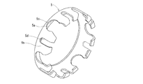
- FIG. 6 is a perspective view of a single holder of the bearing of FIG. 5.
- FIG. 6 is a radial cross-sectional view of the bearing of FIG. 5.
- FIG. 6 is a diagram showing an assembly process of the bearing of FIG. 5.
- FIG. 7 is a perspective view of a holder alone in which a U-shaped slit is provided on a pillar portion of the holder of FIG. 6.
- 1 to 9 show an embodiment in which the present invention is applied to a sealed deep groove ball bearing.
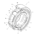
- FIG. 1 is a perspective view of a sealed deep groove ball bearing 1 to which the present invention is applied, and for convenience, the outer ring 2 and the sealing plate 6 are shown by removing the front half of the drawing.
- the bearing 1 includes an outer ring 2 having an outer raceway surface 2a on an inner peripheral surface, an inner race 3 having an inner raceway surface 3a on an outer peripheral surface, a rolling element 4, and a solid lubricant 7 located between the rolling elements 4.
- the cage 5 that separates the rolling elements 4 in the circumferential direction, and the annular plate 8 having the same shape as the annular portion 5a on the axially opposite side of the annular portion 5a of the cage 5 are provided on both sides of the outer ring 2.
- the sealing plate 6 is fixed.
- the outer diameter end of the sealing plate 6 is press-fitted and fixed in the peripheral groove formed on the inner peripheral surface of the outer ring 2, and the inner diameter end thereof is close to the outer peripheral surface of the inner ring 3 to form a non-contact seal.
- the seal plate 6 may be a contact seal type in which the inner diameter end of the seal plate 6 is in sliding contact with the outer peripheral surface of the inner ring 3.
- the outer ring 2, the inner ring 3, the cage 5, and the annular plate 8 are made of a steel material, for example, martensitic stainless steel such as SUS440C.
- the rolling element 4 is made of ceramics, and as the ceramics, for example, silicon nitride can be used. When the rolling elements 4 are not made of ceramics, it is preferable to form a coating film made of a solid lubricating material such as graphite on the surface thereof.
- the sealing plate 6 is preferably made of a steel material, for example, austenitic stainless steel such as SUS304 having excellent corrosion resistance.
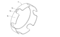
- the cage 5 is a comb cage composed of an annular portion 5a and six column portions 5b extending in the axial direction starting from the outer diameter side of the annular portion 5a.
- the pocket 5c for accommodating the rolling element 4 has a substantially U-shape (a pot shape with a partially constricted portion) penetrating in the radial direction, and the outer diameter surface of the column portion 5b is a partial cylindrical surface corresponding to the inner diameter surface of the outer ring 2. Is done.
- the solid lubricant 7 is located inside the pillar portion 5b of the cage 5, the arrangement of the rolling elements 4 does not change due to wear of the solid lubricant 7.
- the retainer 5 can also be composed of the annular portion 5a and the six pillar portions 5b extending in the axial direction starting from the inner diameter side of the annular portion 5a.
- the inner diameter surface of the column portion 5b forms a partial cylinder corresponding to the outer diameter surface of the inner ring 3, and the solid lubricant 7 is located outside the column portion 5b of the cage 5.
- the solid lubricant 7 is made of, for example, a graphite-based, tungsten disulfide-based, or molybdenum disulfide-based solid lubricant material, and has a plate shape curved along the shape of the bearing ring.
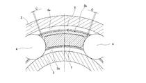
- FIG. 3 is a partial sectional view of the bearing 1 of FIG. 1 divided in the axial direction, and shows a state where the solid lubricant 7 is sandwiched between two rolling elements 4 that are adjacent to each other with the solid lubricant 7 interposed therebetween. At this time, there is a clearance C in the circumferential direction between the two rolling elements 4 and the pillar portion 5b of the cage 5 located between them, and the rolling element 4 is more aggressive with the solid lubricant 7 than the pillar portion 5b. It is configured to come into contact with.
- FIG. 4 is a side view of the bearing 1 of FIG. 1, and for the sake of convenience, the sealing plate 6 and the annular plate 8 on the front side of the drawing are omitted, and a part of the rolling element 4 is shown by a broken line.
- the opening size W of the pocket 5c for accommodating the rolling element 4 of the cage 5 is smaller than the diameter D of the rolling element 4, and the shape of the pocket 5c seen from the radial direction is a vase shape in which a part is constricted. ing.
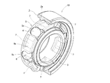
- FIG. 5 is a perspective view of an open type deep groove ball bearing 9 to which the present invention is applied.
- the outer ring 2 is shown by removing the front half of the drawing.
- the same parts as those of the embodiment shown in FIGS. 1 to 4 are designated by the same reference numerals, and the description thereof will be appropriately omitted.
- the bearing 9 includes an outer ring 2 and an inner ring 3 made of stainless steel, a rolling element 4 made of ceramic, a solid lubricant 7 made of a graphite-based solid lubricant material located between the rolling elements 4, and the rolling element 4. It has a cage 5 made of stainless steel plate and spaced apart in the circumferential direction.
- FIG. 6 is a perspective view of the cage 5 alone of the bearing 9 of FIG. 5, and has a shape in which the pillar portion 5b of the cage 5 of FIG. 2 is extended and the tip is bent inward.
- FIG. 7 is a radial cross-sectional view of the bearing 9 of FIG. 5, and the cross-sectional shape of the column portion 5b of the retainer 5 is U-shaped, and supports and guides a part of both end surfaces of the solid lubricant 7. It is composed.
- the width dimension W1 of the solid lubricant 7 is slightly larger than the U-shaped width dimension W2 of the cage 5, and the solid lubricant 7 can be press-fitted into the cage 5.
- the press-fitting margin is worn and worn by the interference force from the rolling element 4 due to the rotation of the bearing 9, and the solid lubricant 7 is allowed to move in the circumferential direction inside the column portion 5b of the cage 5. ing.
- FIG. 8 is a diagram showing an assembling process of the bearing 9 of FIG. 5, in which the sub-assembled cage 5 and the solid lubricant 7 are directed toward the rolling elements 4 arranged between the outer ring 2 and the inner ring 3.
- FIG. The retainer 5 catches the rolling element 4 according to the lead-in chamfer provided in the opening of the pocket 5c, and is inserted in the axial direction while elastically deforming the opening dimension W.
- FIG. 9 is a partial modification of the retainer 5 of the bearing 9 of FIG. 5, in which the pillar portion 5b is provided with a U-shaped slit 5d that opens toward the tip of the comb.
- the present invention is not limited to ball bearings, but can be applied to roller bearings.
- the material and shape of the components are not limited to the above.
- Steel balls made of stainless steel or bearing steel, tungsten disulfide-based or molybdenum disulfide-based solid lubricants, as well as cylindrical members were turned.
- a machined cage can also be used.
Landscapes
- Engineering & Computer Science (AREA)
- General Engineering & Computer Science (AREA)
- Mechanical Engineering (AREA)
- Rolling Contact Bearings (AREA)
Abstract
固体潤滑剤の過剰摩耗や転がり面への過剰移着を抑制することが可能な固体潤滑転がり軸受を提供することを課題とする。内輪3と、外輪2と、複数の転動体4と、隣接する転動体4の間に位置する少なくとも1つの固体潤滑剤7と、転動体4を周方向に離間する保持器5とを備える固体潤滑転がり軸受1において、前記固体潤滑剤7を、転動体4を離間する保持器5の柱部5bの内側または外側に位置させた。
Description
この発明は、高温や真空等の環境下で使用する固体潤滑剤を備えた転がり軸受に関する。
固体潤滑転がり軸受は、潤滑剤としてグリースや潤滑油を使用することができない高温雰囲気や真空雰囲気等で使用される。
この種の固体潤滑転がり軸受として、従来、保持器を使用せず、隣接する転動体の間に固体潤滑剤を配置し、固体潤滑剤が転動体や軌道輪と摺動することにより、潤滑剤が相手部品に移着または潤滑粉が生成されるようにして、軸受内部を潤滑するようにしたものが知られている(特許文献1、2)。
しかしながら、前記従来のいずれの構成も固体潤滑剤が摩耗するにつれて、転動体の周方向の位置に偏りが生じるため、軸受の回転振れ精度が悪化する恐れがある。また、転動体の慣性力が固体潤滑剤に作用する構成であるため、固体潤滑剤が過剰に摩耗して軸受の寿命が短くなることがある。
そこで、この発明は、固体潤滑剤を備えた転がり軸受において、固体潤滑剤が摩耗しても転動体の偏りが発生せず、また、転動体と固体潤滑剤の干渉力を抑制可能な構成を提供しようとするものである。
前記の課題を解決するために、この発明は、内輪と、外輪と、複数の転動体と、転動体の間に位置する少なくとも1つの固体潤滑剤と、転動体を周方向に離間する保持器を有する転がり軸受において、固体潤滑剤が転動体を離間する保持器の柱部の内側または外側に位置する構成を採用した。
上記の構成により、転動体の周方向の位置は保持器のポケットの位置によって決まるため、固体潤滑剤が摩耗しても転動体の偏りが発生せず、軸受の回転振れ精度が悪化しない。また、転動体と固体潤滑剤の干渉力は、転動体ではなく質量の小さい固体潤滑剤の慣性力によって発生するため、固体潤滑剤の摩耗速度が緩和される。
また、固体潤滑剤を介して隣り合う2つの転動体で固体潤滑剤を挟んだときに、2つの転動体とその間に位置する保持器の柱部との間に周方向のすきまがある構成とすることで、運転初期の軸受内部に潤沢な潤滑剤が供給される。すなわち、固体潤滑剤の初期の周方向寸法を保持器の柱部の周方向寸法よりも大きくすることで、運転初期には転動体の慣性力が固体潤滑剤に作用する構成となり、固体潤滑剤が積極的に摩耗する。その後、固体潤滑剤が摩耗して柱部の周方向寸法よりも小さくなると、転動体と固体潤滑剤の干渉力が抑制される段階に移行する。
また、保持器が固体潤滑剤の両端面の一部または全面を支持、案内する構成とすることで、固体潤滑剤の端面が密封板等の周辺部品に摺動せず、摩耗速度が一層緩和される。
また、固体潤滑剤の幅寸法が保持器に対して圧入代を有する構成とすることで、両者のサブアセンブリ化が可能となり、軸受を組み立てる際の取り扱い性が向上する。
また、保持器が円環部と円環部を起点に軸方向に伸びる複数の柱部で構成されるくし形保持器であって、転動体を収容するポケットのくし先端側の開口寸法が、転動体の直径よりも小さい構成とすることで、保持器の軸方向の位置決めを密封板等の周辺部品に依存しない構成となる。すなわち、保持器の径方向から見たポケット形状をとっくり形にして転動体を収めることで、転動体によって保持器の軸方向の移動が制限される構成となる。
また、保持器の柱部がくし先端側に開口するスリットを有する構成とすることで、軸受の組み立てにおいて、保持器を内輪と外輪の間に配列された転動体に圧入を伴って挿入する際、柱部を弾性変形させ易くなるため、軸受の組み立て性が向上するほか、保持器の塑性変形が抑制される。
以上のように、この発明によれば、固体潤滑剤が摩耗しても転動体の偏りが発生しないため、回転振れ精度が悪化しない固体潤滑転がり軸受を提供することができる。また、転動体と固体潤滑剤の干渉力を抑制できるため、固体潤滑剤の過剰摩耗を抑えた長寿命な固体潤滑転がり軸受を提供することができる。
以下、この発明の実施の形態を添付図面に基づいて説明する。
図1~図9は、この発明を密封形深溝玉軸受に適用した実施形態を示している。
図1は、この発明を適用した密封形深溝玉軸受1の斜視図であり、便宜上、外輪2と密封板6は、紙面手前側半分を除去して表示している。
同軸受1は、内周面に外側軌道面2aを有する外輪2と、外周面に内側軌道面3aを有する内輪3と、転動体4と、転動体4の間に位置する固体潤滑剤7と、転動体4を周方向に離間する保持器5と、保持器5の円環部5aの軸方向反対側に前記円環部5aと同様形状の円環板8を備え、外輪2の両側に密封板6が固定されている。
同軸受1は、内周面に外側軌道面2aを有する外輪2と、外周面に内側軌道面3aを有する内輪3と、転動体4と、転動体4の間に位置する固体潤滑剤7と、転動体4を周方向に離間する保持器5と、保持器5の円環部5aの軸方向反対側に前記円環部5aと同様形状の円環板8を備え、外輪2の両側に密封板6が固定されている。
前記密封板6は、その外径端が外輪2の内周面に形成された周溝に圧入固定され、その内径端が内輪3の外周面に近接して非接触シールを形成している。なお、高温環境で使用されない軸受等では、密封板6として、その内径端を内輪3の外周面に摺接させる接触シールタイプを使用することもできる。
外輪2、内輪3、保持器5および円環板8は、鋼材料、例えばSUS440C等のマルテンサイト系ステンレス鋼で形成される。転動体4は、セラミックスで形成され、セラミックスとしては、例えば窒化ケイ素を使用することができる。転動体4をセラミックスで形成しない場合には、その表面にグラファイト等の固体潤滑材料からなる被膜を形成するのが好ましい。密封板6は、鋼材料で形成し、例えば耐食性に優れるSUS304等のオーステナイト系ステンレス鋼で形成するのが好ましい。
保持器5は、円環部5aと円環部5aの外径側を起点に軸方向に伸びる6つの柱部5bで構成されるくし形保持器である。転動体4を収容するポケット5cは径方向に貫通した略Uの字形(一部がくびれた壺形)を成し、柱部5bの外径面は外輪2の内径面に対応した部分円筒面を成している。
ここで、固体潤滑剤7は、保持器5の柱部5bの内側に位置するため、固体潤滑剤7の摩耗によって転動体4の配置が変わることはない。
なお、保持器5は、円環部5aと円環部5aの内径側を起点に軸方向に伸びる6つの柱部5bで構成することもできる。この場合、柱部5bの内径面は内輪3の外径面に対応した部分円筒をなし、固体潤滑剤7は保持器5の柱部5bの外側に位置する構成となる。
固体潤滑剤7は、例えば、グラファイト系、二硫化タングステン系や二硫化モリブデン系の固体潤滑剤材料からなり、軌道輪の形状に沿って湾曲した板状を呈している。
図3は、図1の軸受1を軸方向に分割した部分断面図であり、固体潤滑剤7を介して隣り合う2つの転動体4で固体潤滑剤7を挟んだ状態を示している。このとき、2つの転動体4とその間に位置する保持器5の柱部5bとの間には周方向のすきまCが存在し、転動体4は柱部5bよりも固体潤滑剤7と積極的に接触する構成となっている。
図4は、図1の軸受1の側面図であり、便宜上、紙面手前の密封板6および円環板8を省略し、転動体4の一部を破線で示した。ここで、保持器5の転動体4を収容するポケット5cの開口寸法Wは、転動体4の直径Dよりも小さく、径方向から見たポケット5cの形状は一部がくびれた壺形となっている。
次に、図5は、この発明を適用した開放形深溝玉軸受9の斜視図であり、便宜上、外輪2は紙面手前側半分を除去して表示している。図1~図4に示した実施形態と共通する部位について同一の符号を付し、適宜説明を省略する。
同軸受9は、ステンレス鋼製の外輪2および内輪3と、セラミック製の転動体4と、転動体4の間に位置するグラファイト系固体潤滑剤材料からなる固体潤滑剤7と、転動体4を周方向に離間するステンレス鋼板製の保持器5を有する。
図6は、図5の軸受9の保持器5単体の斜視図であり、図2の保持器5の柱部5bを延長して先端を内側に曲げた形状となっている。
図7は、図5の軸受9の径方向断面図であり、保持器5の柱部5bの断面形状はコの字形を成し、固体潤滑剤7の両端面の一部を支持、案内する構成となっている。また、固体潤滑剤7の幅寸法W1は、保持器5のコの字形の幅寸法W2よりも僅かに大きく、保持器5に固体潤滑剤7を圧入できる構成となっている。なお、その圧入代は、軸受9の回転による転動体4からの干渉力を受けて摩耗、摩滅し、固体潤滑剤7は保持器5の柱部5bの内側で周方向にも遊動できるようにしている。
図8は、図5の軸受9の組み立て過程を示した図であり、サブアセンブリ化された保持器5と固体潤滑剤7を、外輪2と内輪3の間に配列された転動体4に向かって挿入する際の図である。保持器5は、ポケット5cの開口部に設けられたリードインチャンファにしたがって転動体4を捉え、開口寸法Wを弾性変形させながら軸方向に挿入される。
図9は、図5の軸受9の保持器5を一部変更したものであり、柱部5bに、くし先端側に開口するUの字形のスリット5dを設けている。
なお、この発明は玉軸受に限定されるものではなく、ころ軸受にも適用することができる。また、構成部品の材質や形状も上記に限定されるものではなく、ステンレス鋼や軸受鋼製の鋼球、二硫化タングステン系や二硫化モリブデン系の固体潤滑剤のほか、円筒部材を旋削加工したもみ抜き保持器を採用することもできる。
1 :密封形深溝玉軸受
2 :外輪
2a :外側軌道面
3 :内輪
3a :内側軌道面
4 :転動体
5 :保持器
5a :円環部
5b :柱部
5c :ポケット
5d :スリット
6 :密封板
7 :固体潤滑剤
8 :円環板
9 :開放形深溝玉軸受
2 :外輪
2a :外側軌道面
3 :内輪
3a :内側軌道面
4 :転動体
5 :保持器
5a :円環部
5b :柱部
5c :ポケット
5d :スリット
6 :密封板
7 :固体潤滑剤
8 :円環板
9 :開放形深溝玉軸受
Claims (6)
- 内輪と、外輪と、複数の転動体と、転動体の間に位置する少なくとも1つの固体潤滑剤と、転動体を周方向に離間する保持器を有する固体潤滑転がり軸受において、
固体潤滑剤が転動体を離間する保持器の柱部の内側または外側に位置する固体潤滑転がり軸受。 - 固体潤滑剤を介して隣り合う2つの転動体で固体潤滑剤を挟んだときに、2つの転動体とその間に位置する保持器の柱部との間に周方向のすきまがある請求項1に記載の固体潤滑転がり軸受。
- 保持器が固体潤滑剤の両端面の一部または全面を支持、案内する請求項1または2に記載の固体潤滑転がり軸受。
- 固体潤滑剤の幅寸法が保持器に対して圧入代を有する請求項3に記載の固体潤滑転がり軸受。
- 保持器が円環部と円環部を起点に軸方向に伸びる複数の柱部で構成されるくし形保持器であって、転動体を収容するポケットのくし先端側の開口寸法が、転動体の直径よりも小さい請求項1ないし4のいずれかの項に記載の固体潤滑転がり軸受。
- 保持器の柱部がくし先端側に開口するスリットを有する請求項5に記載の固体潤滑転がり軸受。
Priority Applications (1)
| Application Number | Priority Date | Filing Date | Title |
|---|---|---|---|
| DE112020000733.2T DE112020000733T5 (de) | 2019-02-07 | 2020-01-24 | Festschmierstoff-Wälzlager |
Applications Claiming Priority (2)
| Application Number | Priority Date | Filing Date | Title |
|---|---|---|---|
| JP2019020533A JP2020128757A (ja) | 2019-02-07 | 2019-02-07 | 固体潤滑転がり軸受 |
| JP2019-020533 | 2019-02-07 |
Publications (1)
| Publication Number | Publication Date |
|---|---|
| WO2020162222A1 true WO2020162222A1 (ja) | 2020-08-13 |
Family
ID=71947174
Family Applications (1)
| Application Number | Title | Priority Date | Filing Date |
|---|---|---|---|
| PCT/JP2020/002466 Ceased WO2020162222A1 (ja) | 2019-02-07 | 2020-01-24 | 固体潤滑転がり軸受 |
Country Status (4)
| Country | Link |
|---|---|
| JP (1) | JP2020128757A (ja) |
| DE (1) | DE112020000733T5 (ja) |
| TW (1) | TW202037822A (ja) |
| WO (1) | WO2020162222A1 (ja) |
Families Citing this family (1)
| Publication number | Priority date | Publication date | Assignee | Title |
|---|---|---|---|---|
| JP2022088835A (ja) * | 2020-12-03 | 2022-06-15 | Ntn株式会社 | 固体潤滑転がり軸受 |
Citations (5)
| Publication number | Priority date | Publication date | Assignee | Title |
|---|---|---|---|---|
| JPH0618730U (ja) * | 1992-08-18 | 1994-03-11 | エヌティエヌ株式会社 | 転がり軸受 |
| JPH0763222A (ja) * | 1993-08-27 | 1995-03-07 | Koyo Seiko Co Ltd | 玉軸受用冠型保持器 |
| JP2009236314A (ja) * | 2008-03-03 | 2009-10-15 | Nsk Ltd | 玉軸受 |
| JP2010065752A (ja) * | 2008-09-10 | 2010-03-25 | Ntn Corp | ころ軸受 |
| JP2017015206A (ja) * | 2015-07-03 | 2017-01-19 | 日本電産シンポ株式会社 | 軸受および減速機 |
Family Cites Families (2)
| Publication number | Priority date | Publication date | Assignee | Title |
|---|---|---|---|---|
| CA958244A (en) | 1971-07-28 | 1974-11-26 | Tommy K. Griffin | Meter prover apparatus and method |
| JP6275433B2 (ja) | 2013-09-19 | 2018-02-07 | Ntn株式会社 | 固体潤滑転がり軸受 |
-
2019
- 2019-02-07 JP JP2019020533A patent/JP2020128757A/ja active Pending
-
2020
- 2020-01-24 WO PCT/JP2020/002466 patent/WO2020162222A1/ja not_active Ceased
- 2020-01-24 DE DE112020000733.2T patent/DE112020000733T5/de not_active Withdrawn
- 2020-02-06 TW TW109103706A patent/TW202037822A/zh unknown
Patent Citations (5)
| Publication number | Priority date | Publication date | Assignee | Title |
|---|---|---|---|---|
| JPH0618730U (ja) * | 1992-08-18 | 1994-03-11 | エヌティエヌ株式会社 | 転がり軸受 |
| JPH0763222A (ja) * | 1993-08-27 | 1995-03-07 | Koyo Seiko Co Ltd | 玉軸受用冠型保持器 |
| JP2009236314A (ja) * | 2008-03-03 | 2009-10-15 | Nsk Ltd | 玉軸受 |
| JP2010065752A (ja) * | 2008-09-10 | 2010-03-25 | Ntn Corp | ころ軸受 |
| JP2017015206A (ja) * | 2015-07-03 | 2017-01-19 | 日本電産シンポ株式会社 | 軸受および減速機 |
Also Published As
| Publication number | Publication date |
|---|---|
| DE112020000733T5 (de) | 2021-10-21 |
| JP2020128757A (ja) | 2020-08-27 |
| TW202037822A (zh) | 2020-10-16 |
Similar Documents
| Publication | Publication Date | Title |
|---|---|---|
| JP2002235812A (ja) | ころ軸受及びころ軸受を組み込んだローラチェーン | |
| JP6565366B2 (ja) | アンギュラ玉軸受 | |
| US6817769B2 (en) | Roller bearing having high performance bearing seal and cartridge | |
| JP2008196582A (ja) | 遊星回転体用円錐ころ軸受 | |
| JP2005133818A (ja) | 転がり軸受 | |
| JP2020128757A (ja) | 固体潤滑転がり軸受 | |
| JP2006329218A (ja) | 転がり軸受用保持器 | |
| CN104791380A (zh) | 调心滚子轴承 | |
| JP2019157936A (ja) | 有限ボールスプライン | |
| WO2020162448A1 (ja) | 固体潤滑転がり軸受 | |
| JP2009085277A (ja) | 転がり軸受用密封装置及びグリース潤滑転がり軸受 | |
| JP2022088835A (ja) | 固体潤滑転がり軸受 | |
| JP2008032089A (ja) | スラストころ軸受 | |
| JP2001116055A (ja) | 複列円すいころ軸受 | |
| KR20220105443A (ko) | 무급유형 베어링. | |
| WO2021187032A1 (ja) | 固体潤滑転がり軸受 | |
| JP2018168871A (ja) | フォロア軸受 | |
| WO2021171879A1 (ja) | 固体潤滑転がり軸受 | |
| JP2554505B2 (ja) | 円すいころ軸受 | |
| WO2019151476A1 (ja) | 転がり軸受 | |
| JP2020118240A (ja) | 固体潤滑転がり軸受 | |
| JP2011231863A (ja) | 複列軸受用保持器および複列転がり軸受 | |
| JP2006118696A (ja) | スラストころ軸受 | |
| JP2016196945A (ja) | 転がり軸受 | |
| JP6606903B2 (ja) | 転がり軸受 |
Legal Events
| Date | Code | Title | Description |
|---|---|---|---|
| 121 | Ep: the epo has been informed by wipo that ep was designated in this application |
Ref document number: 20752774 Country of ref document: EP Kind code of ref document: A1 |
|
| 122 | Ep: pct application non-entry in european phase |
Ref document number: 20752774 Country of ref document: EP Kind code of ref document: A1 |