WO2020162201A1 - レーダー取付構造 - Google Patents
レーダー取付構造 Download PDFInfo
- Publication number
- WO2020162201A1 WO2020162201A1 PCT/JP2020/002260 JP2020002260W WO2020162201A1 WO 2020162201 A1 WO2020162201 A1 WO 2020162201A1 JP 2020002260 W JP2020002260 W JP 2020002260W WO 2020162201 A1 WO2020162201 A1 WO 2020162201A1
- Authority
- WO
- WIPO (PCT)
- Prior art keywords
- bracket
- vehicle
- mounting structure
- radar
- bent
- Prior art date
- Legal status (The legal status is an assumption and is not a legal conclusion. Google has not performed a legal analysis and makes no representation as to the accuracy of the status listed.)
- Ceased
Links
Images




Classifications
-
- B—PERFORMING OPERATIONS; TRANSPORTING
- B60—VEHICLES IN GENERAL
- B60R—VEHICLES, VEHICLE FITTINGS, OR VEHICLE PARTS, NOT OTHERWISE PROVIDED FOR
- B60R21/00—Arrangements or fittings on vehicles for protecting or preventing injuries to occupants or pedestrians in case of accidents or other traffic risks
- B60R21/01—Electrical circuits for triggering passive safety arrangements, e.g. airbags, safety belt tighteners, in case of vehicle accidents or impending vehicle accidents
- B60R21/013—Electrical circuits for triggering passive safety arrangements, e.g. airbags, safety belt tighteners, in case of vehicle accidents or impending vehicle accidents including means for detecting collisions, impending collisions or roll-over
- B60R21/0134—Electrical circuits for triggering passive safety arrangements, e.g. airbags, safety belt tighteners, in case of vehicle accidents or impending vehicle accidents including means for detecting collisions, impending collisions or roll-over responsive to imminent contact with an obstacle, e.g. using radar systems
-
- B—PERFORMING OPERATIONS; TRANSPORTING
- B62—LAND VEHICLES FOR TRAVELLING OTHERWISE THAN ON RAILS
- B62D—MOTOR VEHICLES; TRAILERS
- B62D25/00—Superstructure or monocoque structure sub-units; Parts or details thereof not otherwise provided for
- B62D25/08—Front or rear portions
-
- G—PHYSICS
- G01—MEASURING; TESTING
- G01S—RADIO DIRECTION-FINDING; RADIO NAVIGATION; DETERMINING DISTANCE OR VELOCITY BY USE OF RADIO WAVES; LOCATING OR PRESENCE-DETECTING BY USE OF THE REFLECTION OR RERADIATION OF RADIO WAVES; ANALOGOUS ARRANGEMENTS USING OTHER WAVES
- G01S7/00—Details of systems according to groups G01S13/00, G01S15/00, G01S17/00
- G01S7/02—Details of systems according to groups G01S13/00, G01S15/00, G01S17/00 of systems according to group G01S13/00
- G01S7/03—Details of HF subsystems specially adapted therefor, e.g. common to transmitter and receiver
Definitions
- the present invention relates to a mounting structure for a radar device mounted on a vehicle.
- a radar device for detecting an object in front of the vehicle is arranged inside a bumper fascia or a grill, and a radar device for detecting an object behind the vehicle is arranged inside a rear bumper.
- the existing radar device has a problem that it is difficult to adopt a mounting structure that improves both shock absorption and stability of the mounting state.
- One of the objects of the present invention was devised in view of the above problems, and provides a radar mounting structure capable of improving both shock absorption and stability of mounting state. Is. It should be noted that the present invention is not limited to this purpose, and it is also possible to obtain operational effects that are derived from the respective configurations described in “Modes for Carrying Out the Invention” to be described later and that cannot be obtained by conventional techniques. Can be positioned as a purpose.
- the disclosed radar mounting structure is a mounting structure for a radar device mounted on a vehicle.
- This structure includes a bridging member that vertically connects between two horizontal members arranged at different heights at the front end portion or the rear end portion of the vehicle, and a first bracket fixed to the radar device.
- the second bracket includes an arm portion that obliquely connects the first bracket and the bridging member, and fixes the first bracket to the bridging member.
- the arm portion is provided so as to extend at an ascending slope toward the outside of the vehicle in a side view of the vehicle.
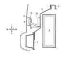
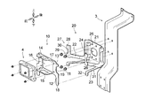
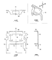
- FIG. 1 is a perspective view of a vehicle to which a radar mounting structure as an example is applied. It is sectional drawing of a radar attachment structure. It is a perspective view of a radar attachment structure. It is an exploded perspective view of a radar attachment structure. It is a trihedral view (top view, front view, side view) and perspective view of a protection bracket. It is a three-sided view (top view, front view, side view) and perspective view of the EA bracket. It is a figure for demonstrating the joined state of a protection bracket and an EA bracket. (A), (B) is a figure for explaining a deformed shape.
- a radar mounting structure as an embodiment will be described with reference to FIGS. 1 to 8.
- This radar mounting structure is a mounting structure for the radar device 4 mounted on the vehicle, and is applied to the inside of the bumper fascia 6 at the front end of the vehicle.
- the bumper fascia 6 is a general term for parts constituting the front surface of the vehicle, and includes a front bumper, a front grill, a headlamp, and the like.
- the radar device 4 is arranged inside the bumper fascia 6. Further, of the bumper fascia 6, a portion located in a transmission/reception range of the electromagnetic wave by the radar device 4 (a portion in front of the radar device 4) is formed of a resin having a property of easily transmitting the electromagnetic wave.
- a bumper beam 1 and an upper bar 2 extend in the vehicle width direction at the front end of the vehicle.
- the bumper beam 1 and the upper bar 2 are structural members arranged inside the bumper fascia 6, and are arranged substantially parallel to each other so that their positions in the height direction are different.
- the bumper beam 1 is a horizontal member arranged below the upper bar 2 and is fixed to a side member, a cross member, or the like.
- the bumper beam 1 of this embodiment is horizontally arranged inside the front bumper. In the vehicle in which the cross member is arranged near the front end of the vehicle, the bumper beam 1 may be read as the cross member.
- the upper bar 2 is a horizontal member for supporting the front end of the bonnet cover, and is horizontally arranged along the upper end side of the heat exchanger 5 such as an oil cooler or radiator arranged at the front end of the vehicle.
- the upper bar 2 of the present embodiment is arranged slightly rearward of the position just above the bumper beam 1.
- the upper end side of the headlamp provided at the front end of the vehicle is also supported by the upper bar 2.
- Both left and right ends of the upper bar 2 are connected to fender panels arranged on the left and right side surfaces of the vehicle.
- a bridging member 3 that connects these in the vertical direction.
- the bridging member 3 is arranged substantially at the center in the vehicle width direction. As shown in FIG. 2, the bridging member 3 has a vertical cross-sectional shape that is stepwise downward toward the front of the vehicle, and the tread surface is inclined downwardly. This prevents interference with the heat exchanger 5 arranged below the upper bar 2.
- the upper end of the bridging member 3 is fixed to the front surface of the upper bar 2, and the lower end of the bridging member 3 is fixed to the rear surface of the bumper beam 1.
- the radar device 4 is attached to the front surface of the bridging member 3 via a protective bracket 10 (first bracket) and an EA bracket 20 (second bracket).
- the EA bracket 20 is a bracket having a function of relieving an impact by bending and deforming with respect to an external force in the vehicle front-rear direction.
- the protective bracket 10 is a bracket having a function of protecting the radar device 4 from an external force.
- the radar device 4 is fastened and fixed to the protective bracket 10, the protective bracket 10 is welded and fixed to the EA bracket 20, and the EA bracket 20 is fastened and fixed to the bridging member 3.
- the fixing means between these members can be changed, and for example, only welding fixing may be adopted.
- the EA bracket 20 is preferably removable from the bridging member 3, and the radar device 4 is preferably removable from the protective bracket 10. In a completed state where these are assembled, as shown in FIG. 2, the radar device 4 is fixed to the bridging member 3 with a space in the vehicle front-rear direction.
- the protective bracket 10 has a shape obtained by partially bending a part stamped from a single plate member, and the shape thereof has a plane of symmetry O shown in FIG. It is symmetrical (mirror-symmetric) as the center.
- the protective bracket 10 is made of metal, it may be formed by bending a die-cut metal plate. Further, when it is made of synthetic resin, it may be molded into such a shape.
- the protective bracket 10 is provided with a frame-shaped portion 11, a lower extension portion 12, a lateral protruding portion 13, an upper guard portion 14, and a lower guard portion 15.
- the frame-shaped portion 11 is a flat plate-shaped portion formed in a frame shape corresponding to the contour shape of the rear surface (or front surface) of the radar device 4.
- An opening 16 is bored in the center of the frame-shaped portion 11 for inserting an antenna wire or a power cable connected to the radar device 4.
- the shape of the opening 16 is smaller than the contour shape of the rear surface (or front surface) of the radar device 4.
- a mounting hole 17 through which a fastener for fastening and fixing the radar device 4 is inserted is provided around the opening 16. When the radar device 4 is fixed to the protective bracket 10 by welding, the mounting hole 17 is unnecessary.
- the lower extension portion 12 is a flat plate-shaped portion extending downward from the vicinity of the lower end portion of the left and right side edges of the frame-shaped portion 11, and the lateral protruding portion 13 is the left and right side edges of the frame-shaped portion 11. It is a flat plate-shaped portion that extends horizontally from to the outside of the vehicle.
- the lower end 18 of the lower extension 12 extends at least below the lower end of the radar device 4.
- the frame-shaped portion 11, the lower extension portion 12, and the lateral projection portion 13 are all arranged with their plate surfaces facing the vehicle front-rear direction (with the normal direction being the vehicle front-rear direction).
- a pair of the lower extension 12 and the lateral protrusion 13 are arranged symmetrically when viewed from the front of the vehicle. Further, a gap having a predetermined dimension P (height direction) is provided between the upper end portion 19 of the lower extension portion 12 and the lateral protruding portion 13.
- the height dimension of the lateral projecting portion 13 is Q
- the height dimension from the upper end portion 19 to the lower end portion 18 of the lower extension portion 12 is R.
- the size of the gap in the vehicle width direction is T
- the size of the lower extension portion 12 in the vehicle width direction is U.
- the width dimension S of the left and right lower extension portions 12 is set to be the same as the width dimension S of the lateral protruding portion 13.
- the upper guard portion 14 and the lower guard portion 15 are portions that are projected outward of the radar device 4 in the vehicle front-rear direction when the radar device 4 is fixed to the protective bracket 10. As shown in FIG. 5, the upper guard portion 14 extends substantially horizontally from the upper end side of the frame-shaped portion 11, and the lower guard portion 15 extends substantially horizontally from the lower end side of the frame-shaped portion 11. The radar device 4 is fixed to the vehicle while being covered by the upper guard portion 14 and the lower guard portion 15 from above and below.
- the upper guard portion 14 and the lower guard portion 15 of the present embodiment are provided with openings for weight reduction, such openings are not an essential structure. Further, the postures of the upper guard portion 14 and the lower guard portion 15 with respect to the frame-shaped portion 11 need not be strictly vertical.
- the EA bracket 20 also has a shape obtained by partially bending a part die-cut from a single plate member, and the shape is symmetrical about a plane of symmetry O (mirror surface). Symmetry).
- O mirror surface
- the EA bracket 20 is made of metal, it may be formed by bending a die-cut metal plate. Further, when it is made of synthetic resin, it may be molded into such a shape.
- the EA bracket 20 is provided with a main body portion 21, an arm portion 22, and a leg portion 23.
- the main body 21 is a portion to which the bridging member 3 is fastened and fixed.
- the main body 21 is formed in a shape such that both left and right ends of a rectangular flat plate are bent toward the front of the vehicle. Ribs and dents for increasing rigidity are provided at the bent portions.
- an opening 24 similar to the opening 16 of the protective bracket 10 is provided in the center of the main body 21.
- a plurality of mounting holes 25 through which fasteners such as nuts and bolt shafts are inserted are bored.
- the EA bracket 20 is fixed to the bridging member 3 by fastening and fixing the main body portion 21 in a state of being in surface contact with the front surface of the bridging member 3.
- the EA bracket 20 is formed to have lower rigidity than the bridging member 3 with respect to an external force in the vehicle front-rear direction (that is, the EA bracket 20 is more easily deformed than the bridging member 3 when an external force acts).
- the arm portion 22 is a flat plate-like member that obliquely connects the protective bracket 10 and the bridging member 3, and extends from the left and right ends of the main body portion 21 toward the front of the vehicle.
- the arm 22 is arranged with the plate surface facing the vehicle width direction (in a posture in which the normal direction is the vehicle width direction). Further, the extending direction of the arm portion 22 is set to a direction in which the outside of the vehicle is inclined upward (a climbing gradient toward the outside of the vehicle) in a side view of the vehicle. Since the present embodiment has the radar mounting structure at the front end of the vehicle, the inclination direction of the arm 22 is a downward slope toward the rear of the vehicle in a side view. In the radar mounting structure at the rear end of the vehicle, the inclination direction of the arm 22 may be a downward slope toward the front of the vehicle in a side view.
- a first bent portion 26 is provided in the middle portion of the arm portion 22.
- the first bent portion 26 is a broken line-shaped portion formed by bending the arm portion 22 so as to project outward in the vehicle width direction of the vehicle, and is parallel to the plate surface of the main body portion 21 in a side view. They are arranged in a straight line.
- the bending angle of the first bending portion 26 is about several degrees (for example, 1 to 5 degrees) in a top view.
- the first bent portion 26 may be formed by slightly bending the arm portion 22.
- the shape of the arm portion 22 may be previously formed into a bent shape.
- the first bent portion 26 is a portion that easily starts bending (folding deformation due to buckling) with respect to an external force acting in the vehicle front-rear direction. That is, by providing the first bent portion 26, the left and right arm portions 22 easily bend with the first bent portion 26 as a fold line, and the cushioning performance is improved.
- a first tip portion 27 that is joined to the protection bracket 10 in a surface contact state with the protection bracket 10 is provided at the tip of the arm portion 22 (on the vehicle front side).
- the first tip portion 27 extends in the up-down direction and is formed to bend outward in the vehicle width direction.
- the first tip portion 27 of the present embodiment is provided with three parts, an upper joint portion 28, a lower joint portion 29, and an intermediate portion 30.
- the upper joining portion 28 is a portion joined to the lateral protrusion 13 of the protection bracket 10.
- the lower joint portion 29 is a portion joined to the lower extension portion 12 of the protective bracket 10 near the upper end portion 19.
- the intermediate portion 30 is a portion that vertically connects the upper joint portion 28 and the lower joint portion 29, and is joined to the frame-shaped portion 11.
- the shape of the first tip portion 27 is formed so as to correspond to the shapes of the lower extension portion 12 and the lateral protrusion portion 13 joined to this.
- the width dimension U of each of the first tip portions 27 and the width dimension S of the left and right first tip portions 27 are the width dimension U of the lower extension portion 12 and the lateral protruding portion 13 shown in FIG.
- width dimension S are set to the same dimension.
- Symbols P to U in FIG. 5 represent the same dimensions as symbols P to U in FIG.
- the leg portion 23 is a flat plate-like member that connects the protective bracket 10 and the bridging member 3 below the arm portion 22, and horizontally extends from the left and right end portions of the lower end side of the main body portion 21 toward the front of the vehicle. It will be extended.
- the plate thickness of the leg portion 23 is the same as the plate thickness of the main body portion 21 and the arm portion 22.
- the leg portions 23 are arranged with their plate surfaces facing up and down (in a posture in which the normal direction is up and down).
- the extending direction of the leg portion 23 need not be strictly horizontal, and may be set to a slope. For example, the outside of the vehicle may be tilted downward (downward slope toward the outside of the vehicle) in a side view of the vehicle.
- the rigidity of the EA bracket 20 is improved by making the slope of the leg portion 23 in the side view of the vehicle opposite to the slope of the arm portion 22.
- a second bent portion 31 is provided in the middle of the leg portion 23.
- the second bent portion 31 is a broken line-shaped portion formed by bending the leg portion 23 downwardly of the vehicle, and is arranged in a straight line parallel to the plate surface of the main body portion 21 in a top view. To be done.
- the bending angle of the second bending portion 31 is, like the first bending portion 26, approximately several degrees (for example, 1 to 5 degrees) in a side view.
- the second bent portion 31 may be formed by slightly bending the leg portion 23.
- the leg portion 23 may be formed in a bent shape in advance.
- the second bending portion 31 is a portion that easily starts bending (folding deformation due to buckling) with respect to an external force acting in the vehicle front-rear direction. Providing the second bent portion 31 facilitates bending of the left and right legs 23 with the second bent portion 31 as a fold line, thereby improving the cushioning performance.
- the second bent portion 31 is arranged so as to be located on the same plane as the first bent portion 26.
- a plane in which the first bent portion 26 and the second bent portion 31 exist is indicated by a symbol V in FIG.
- the buffer performance is further improved.
- the first bent portion 26 acts so as to project the arm portion 22 outward in the vehicle width direction
- the second bent portion 31 acts so as to project the leg portion 23 downward.
- a second tip portion 32 which is joined to the protection bracket 10 in surface contact with the protection bracket 10, is provided at the tip of the leg portion 23 (on the vehicle front side).
- the second tip portion 32 is formed in a shape in which the tip on the protection bracket 10 side is bent downward.
- the second tip 32 of the present embodiment is joined to the lower extension 12 of the protective bracket 10 near the lower end 18.
- the shape of the second tip portion 32 is formed so as to correspond to the shape of the lower extension portion 12 joined thereto.
- the width dimension U of each second tip portion 32 and the width dimension S of the left and right second tip portions 32 are the width dimension U of the lower extension portion 12 and the lateral protrusion portion 13 shown in FIG.
- width dimension S are set to the same dimension.
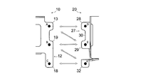
- FIG. 7 is a diagram showing welding points (black circles) when spot welding the protective bracket 10 and the EA bracket 20.
- the welding points on the side of the protective bracket 10 are a point A set on the lateral protrusion 13 and points B and C set on the upper end 19 and the lower end 18 of the lower extension 12.
- the welding points of the EA bracket 20 are points D and E set on the upper joining portion 28 and the lower joining portion 29 of the first tip portion 27, and a point F set on the second tip portion 32.
- the points B and C of the protection bracket 10 are set on the same lower extension 12, whereas the point A is set on the lateral protrusion 13 separated from the lower extension 12. Therefore, in the protection bracket 10 alone, relative displacement tends to occur between the points A and B when the external force acts. On the other hand, in the present embodiment, since the points A and B are welded to the points D and E set on the same first tip portion 27, the relative displacement between the points A and B is suppressed, The rigidity as a whole is secured.
- the point F of the EA bracket 20 is set to the second tip portion 32 which is separated from the first tip portion 27. Therefore, in the EA bracket 20 alone, relative displacement is likely to occur between the points E and F when the external force acts. On the other hand, in the present embodiment, since the points E and F are welded to the points B and C set in the same lower extension portion 12, the relative displacement between the points E and F is suppressed, and the entire The rigidity as is secured.
- the leg 23, which serves as an external force transmission path, is also provided with the second bent portion 31, the leg 23 is bent and deformed downward, and the impact of the external force is absorbed.
- the EA bracket 20 is compressed in a bellows shape by causing the arm portions 22 and the leg portions 23 to project in the vehicle width direction while being crushed in the vehicle front-rear direction. As a result, the impact of external force is efficiently absorbed.
- the radar device 4 is fixed to the bridging member 3 via the protective bracket 10 and the EA bracket 20. Further, the EA bracket 20 is provided with an arm portion 22, and the inclination thereof is set to an ascending inclination toward the outside of the vehicle in a side view of the vehicle.
- the external force in the vehicle front-rear direction can be absorbed while being dispersed downward, and the shock absorption can be improved.
- the arm 22 is provided with the first bent portion 26.
- the first bent portion 26 is bent and formed in a shape protruding outward in the vehicle width direction of the vehicle. Thereby, it is possible to promote the bending with the first bent portion 26 as a broken line, and it is possible to improve the cushioning performance. Further, since the position at which the arm portion 22 starts to be bent and deformed due to buckling is specified, it is possible to prevent interference with other parts during bending and deformation.
- the arm 22 is provided with the first tip 27.
- the first tip portion 27 is formed in a shape in which the tip on the protective bracket 10 side is bent outward in the vehicle width direction, and is joined in a state of surface contact with the protective bracket 10.
- the external force from the protective bracket 10 can be reliably transmitted to the bridging member 3, and the cushioning performance can be improved while ensuring the rigidity with respect to the external force.
- the arm portion 22 can be easily compressed into a bellows shape, and shock absorption is further improved. Can be improved.
- the arm portion 22 is formed in a flat plate shape, and the plate surface is arranged so as to face the vehicle width direction. With such a configuration, it is possible to improve the cushioning performance while ensuring the rigidity of the arm portion 22.
- the arm portion 22 is made of metal, the first bent portion 26 can be easily formed by bending the plate surface, and the manufacturing cost can be reduced.
- the EA bracket 20 is provided with the leg portion 23.
- the leg portion 23 horizontally connects the protective bracket 10 and the bridging member 3 below the arm portion 22.
- the leg 23 is provided with the second bent portion 31.
- the second bent portion 31 is bent and formed in a shape protruding downward of the vehicle. Thereby, it is possible to promote bending with the second bent portion 31 as a broken line, and it is possible to improve the cushioning performance. Further, since the position where the leg portion 23 starts to be bent and deformed due to buckling is specified, it is possible to prevent interference with other parts during bending and deformation.
- the leg portion 23 is provided with the second tip portion 32.
- the second tip portion 32 is formed in a shape in which the tip on the protective bracket 10 side is bent downward, and is joined to the protective bracket 10 in a surface contact state.
- the external force from the protective bracket 10 can be reliably transmitted to the bridging member 3, and the cushioning performance can be improved while ensuring the rigidity against the external force.
- the leg portion 23 can be easily compressed into a bellows shape, and the shock absorbing property can be further improved.
- the leg portion 23 is formed in a flat plate shape, and the plate surface is arranged so as to face the vertical direction. With such a configuration, the downward bending deformation of the leg portion 23 can be promoted, and the cushioning performance can be improved. Further, when the arm portion 22 is made of metal, the second bent portion 31 can be easily formed by bending the plate surface, and the manufacturing cost can be reduced. (10) In the above radar mounting structure, the arm 22 is joined to the lower extension 12 and the lateral protrusion 13 of the protective bracket 10. As a result, the left and right ends of the frame-shaped portion 11 and the lower portions thereof can be supported by the EA bracket 20, and the rigidity against external force can be increased.
- the EA bracket 20 including the arm portion 22 and the leg portion 23 is illustrated, but the leg portion 23 can be omitted.
- the arm portion 22 is provided on the EA bracket 20, and the extending direction thereof is a climbing gradient toward the outside of the vehicle in a side view of the vehicle, whereby shock absorption against external force can be improved and the radar device 4 is provided. It is possible to improve the stability of the mounting state of.
Landscapes
- Engineering & Computer Science (AREA)
- Mechanical Engineering (AREA)
- Radar, Positioning & Navigation (AREA)
- Remote Sensing (AREA)
- Chemical & Material Sciences (AREA)
- Combustion & Propulsion (AREA)
- Transportation (AREA)
- Computer Networks & Wireless Communication (AREA)
- Physics & Mathematics (AREA)
- General Physics & Mathematics (AREA)
- Radar Systems Or Details Thereof (AREA)
- Body Structure For Vehicles (AREA)
Abstract
開示のレーダー取付構造(10)は、橋渡し部材(3)と第一ブラケット(10)と第二ブラケット(20)とを備える。橋渡し部材(3)は、車両の前端部または後端部にて異なる高さで配置される二本の横架材の間を上下方向に接続する。第一ブラケット(10)は、レーダー装置(4)に固定される。第二ブラケット(20)は、第一ブラケット(10)と橋渡し部材(3)との間を斜めに接続する腕部(22)を有し、第一ブラケット(10)を橋渡し部材(3)に対して固定する。腕部(22)は、車両の側面視にて車両の外側に向かう登り勾配で延設される。
Description
本発明は、車両に搭載されるレーダー装置の取付構造に関する。
従来、車両の前後端部にレーダー装置を配置し、車両周囲の物体や他車両,歩行者などの存在をいち早く検出して、乗員への注意喚起や自動ブレーキを実施する技術が開発されている。車両前方の対象を検出するためのレーダー装置はバンパーフェイシャやグリルの内側に配置され、車両後方の対象を検出するためのレーダー装置はリアバンパーの内側に配置される。レーダー装置を車両の前後端に配置することで、電磁波の照射範囲や検出範囲が確保される。一方、レーダー装置の配設位置を車両の外縁部近傍に設定することで、外力がレーダー装置に入力されやすくなり、レーダー装置の保護性が低下しうる。そこで、外力に対する緩衝機能を持つ各種のレーダー取付構造が提案されている(特許文献1~4参照)。
しかしながら、緩衝性能を向上させるほどブラケットの剛性が低下しやすくなり、取付状態が安定しにくくなる。反対に、ブラケットの剛性を高めることで変形が抑制される構造を採用した場合には、外力の衝撃を十分に吸収できなくなるおそれがある。このように、既存のレーダー装置には、衝撃吸収性と取付状態の安定性とをともに向上させる取付構造を採用しにくいという課題がある。
本件の目的の一つは、上記のような課題に鑑みて創案されたものであり、衝撃吸収性と取付状態の安定性とをともに向上させることができるようにしたレーダー取付構造を提供することである。なお、この目的に限らず、後述する「発明を実施するための形態」に示す各構成から導き出される作用効果であって、従来の技術では得られない作用効果を奏することも、本件の他の目的として位置付けることができる。
開示のレーダー取付構造は、車両に搭載されるレーダー装置の取付構造である。本構造は、前記車両の前端部または後端部にて異なる高さで配置される二本の横架材の間を上下方向に接続する橋渡し部材と、前記レーダー装置に固定される第一ブラケットとを備える。また、前記第一ブラケットと前記橋渡し部材との間を斜めに接続する腕部を有し、前記第一ブラケットを前記橋渡し部材に対して固定する第二ブラケットを備える。前記腕部は、前記車両の側面視にて前記車両の外側に向かう登り勾配で延設される。
第一ブラケットと橋渡し部材との間を腕部で斜めに接続し、その勾配を車両の外側に向かう登り勾配にすることで、外力に対する剛性を確保しつつその衝撃を和らげることができ、衝撃吸収性と取付状態の安定性とをともに向上させることができる。
[1.構成]
図1~図8を参照して、実施例としてのレーダー取付構造を説明する。このレーダー取付構造は、車両に搭載されるレーダー装置4の取付構造であって、車両前端部のバンパーフェイシャ6の内側に適用される。バンパーフェイシャ6とは、車両前面の表面を構成する部品の総称であり、フロントバンパー,フロントグリル,ヘッドランプなどがこれに含まれる。レーダー装置4は、バンパーフェイシャ6の内側に配置される。また、バンパーフェイシャ6のうち、レーダー装置4による電磁波の送受信範囲内に位置する部分(レーダー装置4よりも前方の部分)は、電磁波を透過させやすい特性を持った樹脂で形成される。
図1~図8を参照して、実施例としてのレーダー取付構造を説明する。このレーダー取付構造は、車両に搭載されるレーダー装置4の取付構造であって、車両前端部のバンパーフェイシャ6の内側に適用される。バンパーフェイシャ6とは、車両前面の表面を構成する部品の総称であり、フロントバンパー,フロントグリル,ヘッドランプなどがこれに含まれる。レーダー装置4は、バンパーフェイシャ6の内側に配置される。また、バンパーフェイシャ6のうち、レーダー装置4による電磁波の送受信範囲内に位置する部分(レーダー装置4よりも前方の部分)は、電磁波を透過させやすい特性を持った樹脂で形成される。
図1に示すように、車両前端部には、バンパービーム1とアッパーバー2とが車幅方向に延設される。これらのバンパービーム1及びアッパーバー2は、バンパーフェイシャ6の内側に配置される構造部材であり、高さ方向の位置が相違するように、互いにほぼ平行に配置される。
バンパービーム1は、アッパーバー2よりも下方に配置される横架材であり、サイドメンバやクロスメンバなどに固定される。本実施形態のバンパービーム1は、フロントバンパーの内側で水平に配置される。クロスメンバが車両前端部近傍に配置された車両においては、バンパービーム1をクロスメンバと読み替えてもよい。
バンパービーム1は、アッパーバー2よりも下方に配置される横架材であり、サイドメンバやクロスメンバなどに固定される。本実施形態のバンパービーム1は、フロントバンパーの内側で水平に配置される。クロスメンバが車両前端部近傍に配置された車両においては、バンパービーム1をクロスメンバと読み替えてもよい。
アッパーバー2は、ボンネットカバーの前端部を支持するための横架材であり、車両前端部に配置されるオイルクーラーやラジエーターなどの熱交換器5の上端辺に沿って水平に配置される。本実施形態のアッパーバー2は、バンパービーム1の直上方よりもやや後方に配置される。車両前端部に設けられるヘッドランプの上端辺も、アッパーバー2に支持される。アッパーバー2の左右両端部は、車両の左右側面に配置されるフェンダーパネルに接続される。
バンパービーム1とアッパーバー2との間には、これらを上下方向に接続する橋渡し部材3が設けられる。橋渡し部材3は、車幅方向のほぼ中央に配置される。図2に示すように、橋渡し部材3の縦断面の形状は、車両前方に向かって下る階段状であって踏面が下り勾配で傾斜した形状に形成される。これにより、アッパーバー2の下方に配置される熱交換器5との干渉が防止される。橋渡し部材3の上端部はアッパーバー2の前面に固定され、橋渡し部材3の下端部はバンパービーム1の後面に固定される。
図3,図4に示すように、レーダー装置4は、橋渡し部材3の前面に対し保護ブラケット10(第一ブラケット)及びEAブラケット20(第二ブラケット)を介して取り付けられる。EAブラケット20は、車両前後方向の外力に対して屈曲変形することで衝撃を緩和する機能を持ったブラケットである。一方、保護ブラケット10は、外力からレーダー装置4を保護する機能を持ったブラケットである。EAブラケット20と保護ブラケット10とを併用することで、レーダー装置4の保護性が向上し、取付状態の安定性が向上するとともに、橋渡し部材3に伝達される衝撃負荷が軽減される。
本実施形態では、レーダー装置4が保護ブラケット10に対して締結固定され、保護ブラケット10がEAブラケット20に対して溶接固定され、EAブラケット20が橋渡し部材3に対して締結固定される。これらの部材間の固定手段は変更可能であり、例えば溶接固定のみを採用してもよい。ただし、メンテナンス性を考慮して、EAブラケット20は橋渡し部材3から取り外し可能であることが好ましく、レーダー装置4が保護ブラケット10から取り外し可能であることが好ましい。これらが組み付けられた完成状態では、図2に示すように、レーダー装置4が橋渡し部材3に対して車両前後方向に間隔を空けて固定される。
図5に示すように、保護ブラケット10は、一枚の板部材から型抜きされた部品を部分的に屈曲させたような形状を有し、その形状は、図5中に示す対称面Oを中心として左右対称(鏡面対称)である。保護ブラケット10を金属製とする場合には、金属板を型抜きしたものを屈曲させて形成すればよい。また、合成樹脂製とする場合には、そのような形状に成型すればよい。保護ブラケット10には、枠状部11,下延長部12,横突出部13,上ガード部14,下ガード部15が設けられる。
枠状部11は、レーダー装置4の後面(または前面)の輪郭形状に対応する枠状に形成された平板状の部位である。枠状部11の中央には、レーダー装置4に接続されるアンテナ線や電源ケーブルなどが挿通される開口部16が穿孔される。開口部16の形状は、レーダー装置4の後面(または前面)の輪郭形状よりも小さい大きさとされる。また、開口部16の周囲には、レーダー装置4を締結固定する締結具が挿通される取付孔17が設けられる。レーダー装置4を保護ブラケット10に溶接固定する場合には、取付孔17は不要である。
下延長部12は、枠状部11の左右側端辺の下端部近傍から下方に向かって延設された平板状の部位であり、横突出部13は、枠状部11の左右側端辺から車両外側に向かって水平に延設された平板状の部位である。下延長部12の下端部18は、少なくともレーダー装置4の下端よりも下方まで延長される。枠状部11,下延長部12,横突出部13はともに、板面を車両前後方向に向けて(法線方向が車両前後方向になる姿勢で)配置される。
下延長部12,横突出部13の各々は、車両の正面視において、左右対称に一対配置される。また、下延長部12の上端部19と横突出部13との間には、所定寸法P(高さ方向)の隙間が設けられる。ここで、横突出部13の高さ寸法をQとし、下延長部12の上端部19から下端部18までの高さ寸法をRとする。また、車幅方向の隙間の寸法をTとし、車幅方向の下延長部12の寸法をUとする。左右の下延長部12の幅寸法Sは、横突出部13の幅寸法Sと同一寸法に設定される。
上ガード部14及び下ガード部15は、レーダー装置4が保護ブラケット10に固定されたときに、レーダー装置4よりも車両前後方向の外側に向かって突設される部位である。図5に示すように、上ガード部14は枠状部11の上端辺からほぼ水平に延設され、下ガード部15は枠状部11の下端辺からほぼ水平に延設される。レーダー装置4は、上ガード部14及び下ガード部15によって上下をカバーされた状態で車両に固定される。なお、本実施形態の上ガード部14及び下ガード部15には、軽量化のための開口部が形成されているが、このような開口部は必須の構造ではない。また、枠状部11に対する上ガード部14及び下ガード部15の姿勢を、厳密に垂直にする必要はない。
図6に示すように、EAブラケット20も、一枚の板部材から型抜きされた部品を部分的に屈曲させたような形状を有し、その形状は対称面Oを中心として左右対称(鏡面対称)である。EAブラケット20を金属製とする場合には、金属板を型抜きしたものを屈曲させて形成すればよい。また、合成樹脂製とする場合には、そのような形状に成型すればよい。EAブラケット20には、本体部21,腕部22,脚部23が設けられる。
本体部21は、橋渡し部材3の締結固定される部位である。本体部21は矩形の平板における左右両端部を車両前方に向かって屈曲させたような形状に形成される。屈曲箇所には、剛性を高めるためのリブやへこみが設けられる。本体部21の中央には、図6に示すように、保護ブラケット10の開口部16と同様の開口部24が設けられる。また、開口部24の周囲には、ナットやボルト軸などの締結具が挿通される複数の取付孔25が穿孔される。本体部21を橋渡し部材3の前面に面接触させた状態で締結固定することで、EAブラケット20が橋渡し部材3に固定される。EAブラケット20は、車両前後方向の外力に対して橋渡し部材3よりも低剛性に(すなわち、外力の作用時に橋渡し部材3よりもEAブラケット20の方が変形しやすいように)形成される。
腕部22は、保護ブラケット10と橋渡し部材3との間を斜めに接続する平板状の部材であり、本体部21の左右両端部から車両前方に向かって延設される。腕部22は、板面を車幅方向に向けて(法線方向が車幅方向になる姿勢で)配置される。また、腕部22の延設方向は、車両の側面視で車両の外側を上方に傾斜させた向き(車両の外側に向かう登り勾配)に設定される。本実施形態は車両前端部のレーダー取付構造であることから、腕部22の傾斜方向が側面視で車両後方に向かって下り勾配の傾斜である。なお、車両後端部のレーダー取付構造においては、腕部22の傾斜方向を側面視で車両前方に向かって下り勾配の傾斜とすればよい。
図6に示すように、腕部22の中間部には、第一屈曲部26が設けられる。この第一屈曲部26は、腕部22を車両の車幅方向外側に突出する形状に屈曲させて形成された折れ線状の部位であり、側面視で本体部21の板面に対して平行な直線状に配置される。第一屈曲部26の屈曲角度は、上面視で数度程度(例えば1~5度)である。EAブラケット20が金属製である場合には、腕部22をわずかに折り曲げることによって、第一屈曲部26を形成すればよい。また、EAブラケット20が合成樹脂製である場合には、あらかじめ腕部22の形状を屈曲した形状に成形すればよい。第一屈曲部26は、車両前後方向に作用する外力に対して、屈曲(座屈による折れ変形)を開始させやすい部位となる。つまり、第一屈曲部26を設けることで、左右の腕部22が第一屈曲部26を折れ線として屈曲しやすくなり、緩衝性能が向上する。
腕部22の先端(車両前方側)には、保護ブラケット10と面接触した状態で保護ブラケット10に接合される第一先端部27が設けられる。第一先端部27は上下方向に延長されるとともに、車幅方向外側に向かって屈曲形成される。本実施形態の第一先端部27には、上接合部28と下接合部29と中間部30との三部位が設けられる。上接合部28は、保護ブラケット10の横突出部13に接合される部位である。下接合部29は、保護ブラケット10の下延長部12における上端部19の近傍に接合される部位である。中間部30は、上接合部28及び下接合部29の間を上下方向に接続する部位であり、枠状部11に接合される。
第一先端部27の形状は、これに接合される下延長部12及び横突出部13の形状に対応するように形成される。例えば図6に示すように、個々の第一先端部27の幅寸法Uや左右の第一先端部27の幅寸法Sは、図5に示す下延長部12及び横突出部13の幅寸法Uや幅寸法Sと同一寸法に設定される。図5中の記号P~Uは、図6中の記号P~Uと同一の寸法を表す。これにより、保護ブラケット10に入力された外力が効率的に腕部22に伝達されやすくなる。
脚部23は、腕部22よりも下方で保護ブラケット10と橋渡し部材3との間を接続する平板状の部材であり、本体部21の下端辺における左右両端部から車両前方に向かって水平に延設される。脚部23の板厚は、本体部21や腕部22の板厚と同一である。脚部23は、板面を上下方向に向けて(法線方向が上下方向になる姿勢で)配置される。脚部23の延設方向は厳密に水平でなくてもよく、勾配に設定してもよい。例えば、車両の側面視で車両の外側を下方に傾斜させた向き(車両の外側に向かう下り勾配)に設定してもよい。車両の側面視における脚部23の勾配を腕部22とは逆勾配にすることで、EAブラケット20の剛性が改善される。
脚部23の中間部には、第二屈曲部31が設けられる。第二屈曲部31は、脚部23を車両の下方に突出する形状に屈曲させて形成された折れ線状の部位であり、上面視で本体部21の板面に対して平行な直線状に配置される。第二屈曲部31の屈曲角度は、第一屈曲部26と同様に、側面視で数度程度(例えば1~5度)である。EAブラケット20が金属製である場合には、脚部23をわずかに折り曲げることによって、第二屈曲部31を形成すればよい。また、EAブラケット20が合成樹脂製である場合には、あらかじめ脚部23の形状を屈曲した形状に成形すればよい。第二屈曲部31は、車両前後方向に作用する外力に対して、屈曲(座屈による折れ変形)を開始させやすい部位となる。第二屈曲部31を設けることで、左右の脚部23が第二屈曲部31を折れ線として屈曲しやすくなり、緩衝性能が向上する。
第二屈曲部31は、第一屈曲部26と同一平面上に位置するように配置される。第一屈曲部26及び第二屈曲部31が存在する平面を、図6中に記号Vで示す。このように、「腕部22が屈曲しやすいライン」と「脚部23が屈曲しやすいライン」とを同一平面上に揃えることで、腕部22及び脚部23が均等に屈曲しやすくなり、緩衝性能がさらに向上する。また、第一屈曲部26が腕部22を車幅方向外側に突出させるように作用するのに対し、第二屈曲部31は脚部23を下方に突出させるように作用する。これにより、屈曲時における腕部22と脚部23との干渉が回避され、緩衝性能がさらに向上する。
脚部23の先端(車両前方側)には、保護ブラケット10と面接触した状態で保護ブラケット10に接合される第二先端部32が設けられる。第二先端部32は、保護ブラケット10側の先端を下方に向かって屈曲させた形状に形成される。本実施形態の第二先端部32は、保護ブラケット10の下延長部12における下端部18の近傍に接合される。第二先端部32の形状は、これに接合される下延長部12の形状に対応するように形成される。例えば図6に示すように、個々の第二先端部32の幅寸法Uや左右の第二先端部32の幅寸法Sは、図5に示す下延長部12及び横突出部13の幅寸法Uや幅寸法Sと同一寸法に設定される。これにより、保護ブラケット10に入力された外力が効率的に腕部22に伝達されやすくなる。
図7は、保護ブラケット10とEAブラケット20とをスポット溶接する場合の溶接点(黒丸部分)を示す図である。ここでは、六個の溶接点のうち車幅方向の一側に位置する三個の溶接点について説明する。保護ブラケット10側の溶接点は、横突出部13に設定される点Aと、下延長部12の上端部19及び下端部18に設定される点B,点Cである。一方、EAブラケット20の溶接点は、第一先端部27の上接合部28及び下接合部29に設定される点D,点Eと、第二先端部32に設定される点Fである。
保護ブラケット10の点B及び点Cは、同一の下延長部12に設定されているのに対し、点Aは下延長部12から離隔した横突出部13に設定されている。そのため、保護ブラケット10単体では、外力の作用時に点Aと点Bとの間に相対変位が生じやすい。一方、本実施形態では、点A及び点Bが同一の第一先端部27に設定された点D及び点Eに溶接されるため、点Aと点Bとの間の相対変位が抑制され、全体としての剛性が確保される。
また、EAブラケット20の点Fは、第一先端部27から離隔した第二先端部32に設定されている。そのため、EAブラケット20単体では、外力の作用時に点Eと点Fとの間に相対変位が生じやすい。一方、本実施形態では、点E及び点Fが同一の下延長部12に設定された点B及び点Cに溶接されるため、点Eと点Fとの間の相対変位が抑制され、全体としての剛性が確保される。
[2.作用,効果]
車両前方からの外力がバンパーフェイシャ6に作用すると、バンパーフェイシャ6が車両の内側に進入して保護ブラケット10に当接し、保護ブラケット10を介してEAブラケット20に外力が入力される。この外力を図8(A)中に黒矢印で示し、EAブラケット20と橋渡し部材3との締結固定位置を黒三角印で示す。外力の伝達経路となる腕部22には第一屈曲部26が設けられているため、腕部22が車両外側に屈曲変形し、外力の衝撃が吸収される。同様に、外力の伝達経路となる脚部23にも第二屈曲部31が設けられているため、脚部23が下方に屈曲変形し、外力の衝撃が吸収される。図8(B)に示すように、EAブラケット20は車両前後方向に押し潰される過程で車幅方向に腕部22,脚部23を突出させて、蛇腹状に圧縮される。これにより、外力の衝撃が効率的に吸収される。
車両前方からの外力がバンパーフェイシャ6に作用すると、バンパーフェイシャ6が車両の内側に進入して保護ブラケット10に当接し、保護ブラケット10を介してEAブラケット20に外力が入力される。この外力を図8(A)中に黒矢印で示し、EAブラケット20と橋渡し部材3との締結固定位置を黒三角印で示す。外力の伝達経路となる腕部22には第一屈曲部26が設けられているため、腕部22が車両外側に屈曲変形し、外力の衝撃が吸収される。同様に、外力の伝達経路となる脚部23にも第二屈曲部31が設けられているため、脚部23が下方に屈曲変形し、外力の衝撃が吸収される。図8(B)に示すように、EAブラケット20は車両前後方向に押し潰される過程で車幅方向に腕部22,脚部23を突出させて、蛇腹状に圧縮される。これにより、外力の衝撃が効率的に吸収される。
(1)上記のレーダー取付構造では、レーダー装置4が保護ブラケット10とEAブラケット20とを介して橋渡し部材3に固定される。また、EAブラケット20には腕部22が設けられ、その勾配が車両の側面視で車両の外側に向かう登り勾配に設定される。このような構造により、車両前後方向の外力を下方向に分散させつつ吸収することができ、衝撃吸収性を向上させることができる。また、車両の内側方向かつ下向きの荷重に対する剛性を確保しつつ、その衝撃を和らげることができ、衝撃吸収性と取付状態の安定性とをともに向上させることができる。
(2)上記のレーダー取付構造では、腕部22に第一屈曲部26が設けられる。第一屈曲部26は、図6に示すように、車両の車幅方向外側に突出する形状に屈曲形成される。これにより、第一屈曲部26を折れ線とした屈曲を促すことができ、緩衝性能を向上させることができる。また、腕部22が座屈による折れ変形を開始する位置が特定されることになるため、屈曲変形時における他部品との干渉を防止することができる。
(3)上記のレーダー取付構造では、腕部22に第一先端部27が設けられる。第一先端部27は、保護ブラケット10側の先端が車幅方向外側に向かって屈曲した形状に形成され、保護ブラケット10と面接触した状態で接合される。これにより、保護ブラケット10からの外力を確実に橋渡し部材3へと伝達させることができ、外力に対する剛性を確保しつつ緩衝性能を向上させることができる。また、第一先端部27の屈曲方向を車幅方向外側にすることで、図8(B)に示すように、腕部22を蛇腹状に圧縮させやすくすることができ、衝撃吸収性をさらに向上させることができる。
(4)上記のレーダー取付構造では、腕部22が平板状に形成され、その板面が車幅方向に向くように配置される。このような構成により、腕部22の剛性を確保しつつ、緩衝性能を向上させることができる。また、腕部22が金属製である場合には、板面を折り曲げることで容易に第一屈曲部26を形成することができ、製造コストを削減することができる。
(5)上記のレーダー取付構造では、EAブラケット20に脚部23が設けられる。脚部23は、腕部22の下方で保護ブラケット10と橋渡し部材3との間を水平に接続する。このような構造により、剛性を高めつつ緩衝性能を向上させることができる。特に、車両の内側方向かつ下向きの荷重に対する剛性を高めることができ、レーダー装置4の取付状態の安定性を向上させることができる。
(6)上記のレーダー取付構造では、脚部23に第二屈曲部31が設けられる。第二屈曲部31は、図6に示すように、車両の下方に突出する形状に屈曲形成される。これにより、第二屈曲部31を折れ線とした屈曲を促すことができ、緩衝性能を向上させることができる。また、脚部23が座屈による折れ変形を開始する位置が特定されることになるため、屈曲変形時における他部品との干渉を防止することができる。
(7)なお、第一屈曲部26と第二屈曲部31とを同一平面上に配置することで、腕部22が屈曲しやすいラインと脚部23が屈曲しやすいラインとを同一平面上に揃えることができる。これにより、腕部22及び脚部23が均等に屈曲させることができ、保護ブラケット10の回転を抑制することができるとともに、緩衝性能をさらに向上させることができる。
(8)上記のレーダー取付構造では、脚部23に第二先端部32が設けられる。第二先端部32は、保護ブラケット10側の先端を下方に向かって屈曲させた形状に形成され、保護ブラケット10と面接触した状態で接合される。これにより、保護ブラケット10からの外力を確実に橋渡し部材3へと伝達させることができ、外力に対する剛性を確保しつつ緩衝性能を向上させることができる。また、第二先端部32の屈曲方向を下方にすることで、脚部23を蛇腹状に圧縮させやすくすることができ、衝撃吸収性をさらに向上させることができる。
(9)上記のレーダー取付構造では、脚部23が平板状に形成され、その板面が上下方向に向くように配置される。このような構成により、脚部23の下方への屈曲変形を促進することができ、緩衝性能を向上させることができる。また、腕部22が金属製である場合には、板面を折り曲げることで容易に第二屈曲部31を形成することができ、製造コストを削減することができる。
(10)上記のレーダー取付構造では、腕部22が保護ブラケット10の下延長部12と横突出部13とに接合されている。これにより、枠状部11の左右両端辺とその下方とをEAブラケット20で支えることができ、外力に対する剛性を高めることができる。
(10)上記のレーダー取付構造では、腕部22が保護ブラケット10の下延長部12と横突出部13とに接合されている。これにより、枠状部11の左右両端辺とその下方とをEAブラケット20で支えることができ、外力に対する剛性を高めることができる。
[3.変形例]
上記の実施形態はあくまでも例示に過ぎず、本実施形態で明示しない種々の変形や技術の適用を排除する意図はない。本実施形態の各構成は、それらの趣旨を逸脱しない範囲で種々変形して実施することができる。また、必要に応じて取捨選択することができ、あるいは適宜組み合わせることができる。
上記の実施形態はあくまでも例示に過ぎず、本実施形態で明示しない種々の変形や技術の適用を排除する意図はない。本実施形態の各構成は、それらの趣旨を逸脱しない範囲で種々変形して実施することができる。また、必要に応じて取捨選択することができ、あるいは適宜組み合わせることができる。
上述の実施形態では、腕部22及び脚部23を備えたEAブラケット20を例示したが、脚部23は省略することができる。少なくとも、EAブラケット20に腕部22を設け、その延設方向を車両の側面視で車両の外側に向かう登り勾配にすることで、外力に対する衝撃吸収性を向上させることができるとともに、レーダー装置4の取付状態の安定性を向上させることができる。
1 バンパービーム(横架材)
2 アッパーバー(横架材)
3 橋渡し部材
4 レーダー装置
5 熱交換器
6 バンパーフェイシャ
10 保護ブラケット(第一ブラケット)
11 枠状部
12 下延長部
13 横突出部
14 上ガード部
15 下ガード部
16 開口部
17 取付孔
18 下端部
19 上端部
20 EAブラケット(第二ブラケット)
21 本体部
22 腕部
23 脚部
24 開口部
25 取付孔
26 第一屈曲部
27 第一先端部
28 上接合部
29 下接合部
30 中間部
31 第二屈曲部
32 第二先端部
2 アッパーバー(横架材)
3 橋渡し部材
4 レーダー装置
5 熱交換器
6 バンパーフェイシャ
10 保護ブラケット(第一ブラケット)
11 枠状部
12 下延長部
13 横突出部
14 上ガード部
15 下ガード部
16 開口部
17 取付孔
18 下端部
19 上端部
20 EAブラケット(第二ブラケット)
21 本体部
22 腕部
23 脚部
24 開口部
25 取付孔
26 第一屈曲部
27 第一先端部
28 上接合部
29 下接合部
30 中間部
31 第二屈曲部
32 第二先端部
Claims (10)
- 車両に搭載されるレーダー装置の取付構造であって、
前記車両の前端部または後端部にて異なる高さで配置される二本の横架材の間を上下方向に接続する橋渡し部材と、
前記レーダー装置に固定される第一ブラケットと、
前記第一ブラケットと前記橋渡し部材との間を斜めに接続する腕部を有し、前記第一ブラケットを前記橋渡し部材に対して固定する第二ブラケットとを備え、
前記腕部が、前記車両の側面視にて前記車両の外側に向かう登り勾配で延設される
ことを特徴とする、レーダー取付構造。 - 前記腕部が、前記車両の車幅方向外側に突出する形状に屈曲形成された第一屈曲部を有する
ことを特徴とする、請求項1記載のレーダー取付構造。 - 前記腕部が、前記第一ブラケット側の先端を車幅方向外側に向かって屈曲形成してなり、前記第一ブラケットと面接触した状態で接合される第一先端部を有する
ことを特徴とする、請求項1または2記載のレーダー取付構造。 - 前記腕部が平板状に形成されるとともに、板面を車幅方向に向けて配置される
ことを特徴とする、請求項1~3のいずれか1項に記載のレーダー取付構造。 - 前記第二ブラケットが、前記腕部よりも下方で前記第一ブラケットと前記橋渡し部材との間を水平に接続する脚部を有する
ことを特徴とする、請求項1~4のいずれか1項に記載のレーダー取付構造。 - 前記脚部が、下方に突出する形状に屈曲形成された第二屈曲部を有する
ことを特徴とする、請求項5記載のレーダー取付構造。 - 前記第一屈曲部及び前記第二屈曲部が、同一平面上に配置される
ことを特徴とする、少なくとも請求項2に従属する請求項6記載のレーダー取付構造。 - 前記脚部が、前記第一ブラケット側の先端を下方に向かって屈曲形成してなり、前記第一ブラケットと面接触した状態で接合される第二先端部を有する
ことを特徴とする、請求項5~7のいずれか1項に記載のレーダー取付構造。 - 前記脚部が平板状に形成されるとともに、板面を上下方向に向けて配置される
ことを特徴とする、請求項5~8のいずれか1項に記載のレーダー取付構造。 - 前記第一ブラケットが、前記レーダー装置の輪郭形状に対応する枠状に形成された枠状部と、前記枠状部の左右側端辺から車両外側に向かって水平に延設された横突出部と、前記枠状部の左右側端辺の下端部近傍から下方に向かって延設された下延長部とを有し、
前記腕部が、前記横突出部と前記下延長部とに接合される
ことを特徴とする、請求項1~9のいずれか1項に記載のレーダー取付構造。
Priority Applications (1)
| Application Number | Priority Date | Filing Date | Title |
|---|---|---|---|
| JP2020571093A JP7063402B2 (ja) | 2019-02-06 | 2020-01-23 | レーダー取付構造 |
Applications Claiming Priority (2)
| Application Number | Priority Date | Filing Date | Title |
|---|---|---|---|
| JP2019019233 | 2019-02-06 | ||
| JP2019-019233 | 2019-08-29 |
Publications (1)
| Publication Number | Publication Date |
|---|---|
| WO2020162201A1 true WO2020162201A1 (ja) | 2020-08-13 |
Family
ID=71947598
Family Applications (1)
| Application Number | Title | Priority Date | Filing Date |
|---|---|---|---|
| PCT/JP2020/002260 Ceased WO2020162201A1 (ja) | 2019-02-06 | 2020-01-23 | レーダー取付構造 |
Country Status (2)
| Country | Link |
|---|---|
| JP (1) | JP7063402B2 (ja) |
| WO (1) | WO2020162201A1 (ja) |
Cited By (5)
| Publication number | Priority date | Publication date | Assignee | Title |
|---|---|---|---|---|
| US20210031701A1 (en) * | 2019-07-31 | 2021-02-04 | Honda Motor Co., Ltd. | Sensor attachment structure for side part of vehicle body |
| JP2024506136A (ja) * | 2021-02-17 | 2024-02-09 | ルノー エス.ア.エス. | レーダー支持体、レドーム、および自動車のシールド、を備える組立体 |
| EP4524000A1 (en) | 2023-09-15 | 2025-03-19 | Suzuki Motor Corporation | Vehicle structure |
| EP4524001A1 (en) | 2023-09-15 | 2025-03-19 | Suzuki Motor Corporation | Vehicle structure |
| EP4733151A1 (en) * | 2024-10-25 | 2026-04-29 | Suzuki Motor Corporation | Vehicle structure |
Citations (5)
| Publication number | Priority date | Publication date | Assignee | Title |
|---|---|---|---|---|
| JP2007085751A (ja) * | 2005-09-20 | 2007-04-05 | Honda Motor Co Ltd | 物体検知装置の取付構造 |
| JP2017083254A (ja) * | 2015-10-27 | 2017-05-18 | スズキ株式会社 | 検出装置取付構造 |
| JP2017139570A (ja) * | 2016-02-02 | 2017-08-10 | 株式会社ニフコ | センサー固定具 |
| JP2018131152A (ja) * | 2017-02-17 | 2018-08-23 | 本田技研工業株式会社 | 車両の前方状況検出機器の取付構造 |
| JP2018134936A (ja) * | 2017-02-21 | 2018-08-30 | 三菱自動車工業株式会社 | レーダー取付構造 |
Family Cites Families (1)
| Publication number | Priority date | Publication date | Assignee | Title |
|---|---|---|---|---|
| JP6728992B2 (ja) * | 2016-05-31 | 2020-07-22 | 三菱自動車工業株式会社 | 車両のレーダー装置の取り付け構造 |
-
2020
- 2020-01-23 WO PCT/JP2020/002260 patent/WO2020162201A1/ja not_active Ceased
- 2020-01-23 JP JP2020571093A patent/JP7063402B2/ja active Active
Patent Citations (5)
| Publication number | Priority date | Publication date | Assignee | Title |
|---|---|---|---|---|
| JP2007085751A (ja) * | 2005-09-20 | 2007-04-05 | Honda Motor Co Ltd | 物体検知装置の取付構造 |
| JP2017083254A (ja) * | 2015-10-27 | 2017-05-18 | スズキ株式会社 | 検出装置取付構造 |
| JP2017139570A (ja) * | 2016-02-02 | 2017-08-10 | 株式会社ニフコ | センサー固定具 |
| JP2018131152A (ja) * | 2017-02-17 | 2018-08-23 | 本田技研工業株式会社 | 車両の前方状況検出機器の取付構造 |
| JP2018134936A (ja) * | 2017-02-21 | 2018-08-30 | 三菱自動車工業株式会社 | レーダー取付構造 |
Cited By (7)
| Publication number | Priority date | Publication date | Assignee | Title |
|---|---|---|---|---|
| US20210031701A1 (en) * | 2019-07-31 | 2021-02-04 | Honda Motor Co., Ltd. | Sensor attachment structure for side part of vehicle body |
| US11938865B2 (en) * | 2019-07-31 | 2024-03-26 | Honda Motor Co., Ltd. | Sensor attachment structure for side part of vehicle body |
| JP2024506136A (ja) * | 2021-02-17 | 2024-02-09 | ルノー エス.ア.エス. | レーダー支持体、レドーム、および自動車のシールド、を備える組立体 |
| JP7850165B2 (ja) | 2021-02-17 | 2026-04-22 | ルノー エス.ア.エス. | レーダー支持体、レドーム、および自動車のシールド、を備える組立体 |
| EP4524000A1 (en) | 2023-09-15 | 2025-03-19 | Suzuki Motor Corporation | Vehicle structure |
| EP4524001A1 (en) | 2023-09-15 | 2025-03-19 | Suzuki Motor Corporation | Vehicle structure |
| EP4733151A1 (en) * | 2024-10-25 | 2026-04-29 | Suzuki Motor Corporation | Vehicle structure |
Also Published As
| Publication number | Publication date |
|---|---|
| JP7063402B2 (ja) | 2022-05-09 |
| JPWO2020162201A1 (ja) | 2021-10-21 |
Similar Documents
| Publication | Publication Date | Title |
|---|---|---|
| JP7063402B2 (ja) | レーダー取付構造 | |
| US10793095B2 (en) | Structure for mounting radar | |
| JP4797726B2 (ja) | 自動車の前部構造 | |
| JP5245674B2 (ja) | 車体構造 | |
| WO2014069113A1 (ja) | フェンダ支持部構造 | |
| JP5633316B2 (ja) | フェンダーブラケットおよび車体前部構造 | |
| JP2002154373A (ja) | 自動車用ヘッドランプの取付け構造 | |
| CN108657280A (zh) | 汽车的前部车身结构 | |
| US10717469B2 (en) | Vehicle body front part structure | |
| CN103129625A (zh) | 车身前部构造 | |
| JP5251442B2 (ja) | 車両用フード構造 | |
| JP6799772B2 (ja) | フロントバンパカバー支持構造 | |
| JP4769169B2 (ja) | 車両用エネルギー吸収部材 | |
| CN105473423A (zh) | 车辆的翼子板支承构造 | |
| JP5553819B2 (ja) | 車両のフェンダパネル支持構造 | |
| JP2018177124A (ja) | 車両前部構造 | |
| JP3981791B2 (ja) | リアバンパーの衝撃吸収構造 | |
| JP2015189406A (ja) | 車両のバンパ装置 | |
| JP4436335B2 (ja) | 車両用バンパー、荷重受け部材、及びこれらを用いた車両 | |
| JP4036219B2 (ja) | 自動車のエンジンフード構造 | |
| JP2017197180A (ja) | 車両の衝撃のためのクラッシュボックス | |
| JP2018165092A (ja) | 自動車の前部車体構造 | |
| JP2023007134A (ja) | 車両後部構造 | |
| JP7782680B2 (ja) | 車両前部構造 | |
| JP7543776B2 (ja) | 車両の後部構造 |
Legal Events
| Date | Code | Title | Description |
|---|---|---|---|
| 121 | Ep: the epo has been informed by wipo that ep was designated in this application |
Ref document number: 20752443 Country of ref document: EP Kind code of ref document: A1 |
|
| ENP | Entry into the national phase |
Ref document number: 2020571093 Country of ref document: JP Kind code of ref document: A |
|
| NENP | Non-entry into the national phase |
Ref country code: DE |
|
| 122 | Ep: pct application non-entry in european phase |
Ref document number: 20752443 Country of ref document: EP Kind code of ref document: A1 |