WO2020158846A1 - 光伝送システム、及び出力調整装置 - Google Patents
光伝送システム、及び出力調整装置 Download PDFInfo
- Publication number
- WO2020158846A1 WO2020158846A1 PCT/JP2020/003345 JP2020003345W WO2020158846A1 WO 2020158846 A1 WO2020158846 A1 WO 2020158846A1 JP 2020003345 W JP2020003345 W JP 2020003345W WO 2020158846 A1 WO2020158846 A1 WO 2020158846A1
- Authority
- WO
- WIPO (PCT)
- Prior art keywords
- signal
- optical
- optical signal
- wavelength
- output
- Prior art date
- Legal status (The legal status is an assumption and is not a legal conclusion. Google has not performed a legal analysis and makes no representation as to the accuracy of the status listed.)
- Ceased
Links
Images



Classifications
-
- H—ELECTRICITY
- H04—ELECTRIC COMMUNICATION TECHNIQUE
- H04B—TRANSMISSION
- H04B10/00—Transmission systems employing electromagnetic waves other than radio-waves, e.g. infrared, visible or ultraviolet light, or employing corpuscular radiation, e.g. quantum communication
- H04B10/29—Repeaters
- H04B10/291—Repeaters in which processing or amplification is carried out without conversion of the main signal from optical form
- H04B10/293—Signal power control
-
- H—ELECTRICITY
- H04—ELECTRIC COMMUNICATION TECHNIQUE
- H04B—TRANSMISSION
- H04B10/00—Transmission systems employing electromagnetic waves other than radio-waves, e.g. infrared, visible or ultraviolet light, or employing corpuscular radiation, e.g. quantum communication
- H04B10/25—Arrangements specific to fibre transmission
- H04B10/2575—Radio-over-fibre, e.g. radio frequency signal modulated onto an optical carrier
- H04B10/25751—Optical arrangements for CATV or video distribution
-
- H—ELECTRICITY
- H04—ELECTRIC COMMUNICATION TECHNIQUE
- H04B—TRANSMISSION
- H04B10/00—Transmission systems employing electromagnetic waves other than radio-waves, e.g. infrared, visible or ultraviolet light, or employing corpuscular radiation, e.g. quantum communication
- H04B10/50—Transmitters
- H04B10/564—Power control
-
- H—ELECTRICITY
- H04—ELECTRIC COMMUNICATION TECHNIQUE
- H04B—TRANSMISSION
- H04B10/00—Transmission systems employing electromagnetic waves other than radio-waves, e.g. infrared, visible or ultraviolet light, or employing corpuscular radiation, e.g. quantum communication
- H04B10/50—Transmitters
- H04B10/572—Wavelength control
Definitions
- the present invention relates to an optical transmission system and an output adjusting device.
- FIG. 7 shows an example of a network configuration of a conventional FTTH type CATV system.
- the conventional FTTH type CATV system includes, for example, a head end, an optical transmission unit, a relay amplifier, an access amplifier, and an optical reception unit installed in each subscriber's house or the like. , And are included.
- the headend receives the radio wave carrying the video signal transmitted from the broadcasting station via a terrestrial transmission tower or artificial satellite, and adjusts the received radio wave such as amplification. Then, the head end outputs an electric signal based on the video signal to the optical transmitter.
- the optical transmitter converts the acquired electric signal into an optical signal and sends the optical signal to an optical transmission line constructed by an optical fiber.
- the optical transmission line is divided into a section of a relay network (hereinafter referred to as “relay NW”) and a section of an access network (hereinafter referred to as “access NW”).
- the relay NW is a communication network that connects the optical transmission unit and the access NW.
- an amplifier (hereinafter referred to as “relay amplifier”) is configured in multiple stages when the transmission distance extends over a long distance. Each relay amplifier sends the amplified optical signal to another relay amplifier in the subsequent stage, sends it to a device in the access NW section, or branches the optical signal by an optical coupler and outputs it to the other stage in the subsequent stage. It is also sent to both the relay amplifier and the device in the access NW section.
- the access NW is a communication network that connects the relay NW and each optical receiving unit that terminates an optical signal.
- a PON (Passive Optical Network) configuration is generally applied to distribute the optical signal output from the relay NW to the optical receivers installed in a plurality of subscriber homes. .. Further, as shown in FIG. 7, an amplifier (hereinafter, referred to as "access amplifier It is sometimes used.
- an FM (Frequency Modulation) batch conversion method is used as an optical transmission method (see Non-Patent Document 1).
- the optical transmitter receives the frequency-multiplexed multi-channel video electric signal output from the head end, and collectively converts the electric signal into a one-channel wide-band FM signal. Further, the optical transmission unit converts the converted FM signal into an optical signal having one wavelength ⁇ by intensity modulation, and sends the optical signal to the optical transmission line.
- the optical receiving unit receives the optical signal of the wavelength ⁇
- the optical receiving unit converts the optical signal into a wide band FM signal by conversion into an electric signal and demodulates it. Thereby, the optical receiver can extract the frequency-multiplexed electrical signal of the multi-channel image from the received optical signal.
- the video to be distributed includes BS (Broadcasting Satellites) broadcasting and 110-degree CS (Communication Satellites) broadcasting, which are distributed from an artificial satellite to the ground using right-handed circularly polarized waves, as well as terrestrial digital broadcasting. Furthermore, from December 2018, BS broadcasting (intermediate frequency: 2224-2681 [MHz (megahertz)]) and 110-degree CS broadcasting (intermediate frequency: 2748-) that are distributed from artificial satellites to the ground using left-handed circularly polarized waves. 3224 [MHz]) has been started as a new 4K/8K satellite broadcast.
- BS Broadcasting Satellites
- 110-degree CS Common Satellites
- the intermediate frequency band used in the new 4K/8K satellite broadcasting is different from the intermediate frequency band used in the existing broadcasting. Therefore, in the case where the existing broadcasting equipment does not support the intermediate frequency of the new 4K/8K satellite broadcasting, the distribution and viewing of the new 4K/8K satellite broadcasting cannot be realized only by the existing broadcasting equipment.
- FIG. 8 shows an example of a network configuration when this method is used.
- a headend compatible with new 4K/8K satellite broadcasting in addition to the network configuration shown in FIG. 7, a headend compatible with new 4K/8K satellite broadcasting, an optical transmission unit, a relay amplifier, and a WDM (Wavelength Division Division Multiplexing; A wavelength division multiplexing) filter is newly installed.
- WDM Widelength Division Division Multiplexing; A wavelength division multiplexing
- the WDM filter multiplexes the optical signal output from the existing broadcast relay amplifier and the optical signal output from the new 4K/8K satellite broadcast-compatible relay amplifier, and combines the multiplexed optical signal (hereinafter , "Combined signal") to the existing access amplifier.
- the wavelength of the output light output from the relay amplifier for existing broadcasting is set to wavelength ⁇ 1
- the wavelength of the output light output from the relay amplifier corresponding to the new 4K/8K satellite broadcasting is set to wavelength ⁇ 2. It is assumed that ⁇ 1 and wavelength ⁇ 2 have different wavelengths.
- the optical receiver for existing broadcasting may be able to receive the optical signal of wavelength ⁇ 1, but may not be able to receive the optical signal of wavelength ⁇ 2.
- an optical fiber amplifier such as EDFA (Erbium-Doped Fiber Amplifier).
- EDFA Erbium-Doped Fiber Amplifier
- This optical fiber amplifier is capable of amplifying the optical signals as a batch even if optical signals of a plurality of wavelengths are input like the access amplifier in the network configuration shown in FIG. There is.
- an optical fiber amplifier equipped with an APC (Automatic Power Control) function even if the input level of the optical signal to the optical fiber amplifier fluctuates, if the fluctuation is within an allowable range.
- the output level of the optical signal can be controlled to be kept constant.
- the APC function only controls the output level for the combined signal to be constant even if the input optical signal is a combined signal of a plurality of optical signals having different wavelengths. That is, for example, as shown in FIG. 8, when the optical signal input to the access amplifier is a multiplexed signal of the optical signal of wavelength ⁇ 1 and the optical signal of wavelength ⁇ 2, the APC function does not Only the output level is controlled to be constant, and the output level of the optical signal of wavelength ⁇ 1 and the output level of the optical signal of wavelength ⁇ 2 are not controlled to be constant.
- the output level of the multiplexed signal output from the access amplifier shown is equivalent to the output level of the optical signal output from the access amplifier of FIG.
- the access amplifier in the network configuration shown in FIG. 8 since it is assumed that the network equipment in the network configuration shown in FIG. 7 is also used for the host equipment of the access amplifier, the access amplifier in the network configuration shown in FIG.
- the input level corresponding to the optical signal of wavelength ⁇ 1 in the input level of the input multiplexed signal is equal to the input level of the optical signal of wavelength ⁇ 1 input to the access amplifier in the network configuration shown in FIG. Is.
- the input level of the optical signal of wavelength ⁇ 1 and the input level of the optical signal of wavelength ⁇ 2 included in the input level of the multiplexed signal input to the access amplifier in the network configuration shown in FIG. 8 are always constant. Not necessarily, it may fluctuate over time. Even if both input levels fluctuate in this way, if the total value of both input levels (that is, the input level of the multiplexed signal) is within the allowable range of the access amplifier specifications, the access amplifier The output level of the optical signal (combined signal) can be kept constant. However, due to the above variation, the ratio between the input level of the optical signal of wavelength ⁇ 1 and the input level of the optical signal of wavelength ⁇ 2 included in the input level of the multiplexed signal input to the access amplifier varies.
- the ratio between the output level of the optical signal of the wavelength ⁇ 1 and the output level of the optical signal of the wavelength ⁇ 2 included in the multiplexed signal output from the access amplifier also changes. Therefore, even if the total value of the input levels of both optical signals is within the allowable range in the specifications of the access amplifier, the output level of the optical signal of wavelength ⁇ 1 and the output level of the optical signal of wavelength ⁇ 2 are At least one of them may be lowered to an output level that cannot be received by an optical receiver installed in, for example, a subscriber's house.
- ITU-T J.185 Transmission equipment for transfer transfer multi-channel television signals over optical access networks networks by frequency modulation conversion
- International Telecommunication Union June 2012.
- an access amplifier for existing broadcasting equipped with the APC function is diverted to construct a network configuration corresponding to new 4K/8K satellite broadcasting as shown in FIG. 8, it is output from the access amplifier.
- At least one of the output level of the optical signal of wavelength ⁇ 1 and the output level of the optical signal of wavelength ⁇ 2 included in the output level of the optical signal (combined signal) that falls below the desired output level is because, as described above, the input of the optical signal of the wavelength ⁇ 2 (for new 4K/8K satellite broadcasting) is newly added to the access amplifier, and the access amplifier is input.
- the input level of the optical signal of wavelength ⁇ 1 and the input level of the optical signal of wavelength ⁇ 2, which are included in the input level of the multiplexed signal can vary.
- the optical receiving section installed in each subscriber's house at least one of the receiving level of the optical signal of wavelength ⁇ 1 and the receiving level of the optical signal of wavelength ⁇ 2 does not reach the viewable receiving level, There is a problem that the viewer may not be able to view a desired video.
- the present invention has been made in view of the above technical background, and an object of the present invention is to provide a technology that enables viewing of existing broadcasts and newly added broadcasts while suppressing installation costs.
- One aspect of the present invention includes a first optical transmitter that transmits a first optical signal having a first wavelength and a second optical signal that has a second wavelength different from the first wavelength.
- a second optical transmission unit, an output adjustment unit that acquires the first optical signal and the second optical signal, and adjusts and outputs the signal intensity of each acquired optical signal, and the output adjustment unit A signal multiplexer for multiplexing the first optical signal and the second optical signal whose signal intensities are respectively adjusted and outputting a multiplexed signal, an amplifier for amplifying the multiplexed signal, and the amplifier
- a first optical receiving unit that receives the first optical signal included in the combined signal amplified by, and a second optical signal included in the combined signal amplified by the amplifier.
- a second optical receiving section wherein the output adjusting section has a signal intensity of the first optical signal received by the first optical receiving section that is equal to or higher than a first predetermined value, and Each of the acquired signal intensities of the first optical signal and the second optical signal is adjusted so that the signal intensity of the second optical signal received by the second optical receiving unit becomes equal to or more than a second predetermined value. It is an optical transmission system for adjustment.
- the output adjusting unit sets the signal intensity of the combined signal output from the amplifier to a third predetermined value.
- the signal intensities of the first optical signal and the second optical signal are respectively adjusted.
- the output adjusting unit includes an insertion loss generated in the multiplexer, the amplifier, the first optical receiving unit, and the second optical unit.
- the signal strengths of the first optical signal and the second optical signal are respectively adjusted based on the transmission loss generated between the receiving section and the receiving section.
- one aspect of the present invention is the optical transmission system described above, further comprising a first filter that passes only the first wavelength and a second filter that passes only the second wavelength.
- the output adjustment unit acquires the first optical signal that has passed through the first filter and the second optical signal that has passed through the second filter, and obtains the signal strength of each acquired optical signal. Adjust and output each.
- One aspect of the present invention is the optical transmission system described above, wherein the first optical signal transmitted from the first optical transmission unit and the second optical signal transmitted from the second optical transmission unit. Further comprising a second multiplexer that multiplexes the optical signal of 1., the output adjusting unit acquires the optical signal that is combined by the second multiplexer, and the acquired optical signal is the first optical signal. Optical signal and the second optical signal are separated, and the signal intensities of the separated first optical signal and second optical signal are adjusted and output.
- the output adjustment unit includes the first predetermined value, an insertion loss generated in the multiplexer, the amplifier and the first optical receiver.
- a first required signal strength which is a signal strength required for the first optical signal included in the combined signal output from the amplifier, based on a transmission loss that occurs between Included in the multiplexed signal output from the amplifier based on the second predetermined value, the insertion loss generated in the multiplexer, and the transmission loss generated between the amplifier and the second optical receiver.
- the second required signal strength which is the signal strength required for the second optical signal to be calculated is calculated, and the amplifier is provided so as to satisfy the first required signal strength and the second required signal strength, respectively.
- a first optical signal having a first wavelength and a second optical signal having a first wavelength that are transmitted to the first optical receiving unit and the second optical receiving unit, respectively are provided.
- the signal intensity of the first optical signal received by the first optical receiving unit is equal to or higher than a first predetermined value, and So that the signal intensity of the second optical signal received by the second optical receiving unit is equal to or greater than a second predetermined value, and the signal intensity of the combined signal output from the amplifier is a third predetermined value.
- An adjustment for calculating respective adjustment amounts for the signal intensity of the first optical signal acquired by the first acquisition unit and the signal intensity of the second optical signal acquired by the second acquisition unit Based on the adjustment amounts calculated by the adjustment amount calculation unit and the adjustment amount calculation unit, the signal intensity of the first optical signal acquired by the first acquisition unit, and the second acquisition unit.
- a signal strength adjusting unit that adjusts the signal strength of the second optical signal obtained by the above, and outputs the first light signal and the second light signal whose signal strength is adjusted. It is an adjusting device.
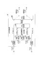
- FIG. 3 is a block diagram showing an example of a network configuration of a new 4K/8K satellite broadcasting compatible FTTH type CATV system. It is a block diagram which shows the network structure of the FTTH type CATV system corresponding to the new 4K/8K satellite broadcasting which concerns on the 3rd Embodiment of this invention.
- FIG. 3 is a block diagram showing an example of a network configuration of a new 4K/8K satellite broadcasting compatible FTTH type CATV system.
- FIG. 1 is a block diagram showing an example of the network configuration.
- the FTTH type CATV system 1 optical transmission system
- the FTTH type CATV system 1 includes a head end 11 for existing broadcasting, an optical transmitter 12, a relay amplifier 13, and a head end compatible with new 4K/8K satellite broadcasting. 21, an optical transmitter 22, a relay amplifier 23, an output adjusting device 30, a WDM filter 40, an access amplifier 50, an existing broadcast optical receiver 61, and new 4K/8K satellite broadcasting.
- the optical receiver 62 is included.
- the headend 11 receives a radio wave carrying an existing broadcast video signal transmitted from a broadcasting station via a terrestrial transmission tower or an artificial satellite, and adjusts the received radio wave such as amplification. Then, the head end 11 sends an electric signal based on the video signal to the optical transmitter 12.
- the optical transmitter 12 (first optical transmitter) converts the received electrical signal into an optical signal of wavelength ⁇ 1 and sends the optical signal to the optical transmission line 70 constructed by an optical fiber.
- the headend 21 receives a radio wave carrying a video signal of a new 4K/8K satellite broadcast transmitted from a broadcasting station via a terrestrial transmission tower or an artificial satellite, and adjusts the received radio wave such as amplification. To do. Then, the head end 21 sends out an electric signal based on the video signal to the optical transmitter 22.
- the optical transmitter 22 (second optical transmitter) converts the received electrical signal into an optical signal of wavelength ⁇ 2 and sends the optical signal to the optical transmission line 70.
- the wavelength ⁇ 1 and the wavelength ⁇ 2 are different from each other.
- the optical transmission line 70 is divided into a section of the relay NW 71 and a section of the access NW 72.
- the relay NW 71 is a communication network that connects the optical transmission unit 12 and the optical transmission unit 22 to the access NW.
- the relay amplifier 13 for existing broadcasting and the relay amplifier 23 for new 4K/8K satellite broadcasting are each configured in multiple stages.
- the optical signal of wavelength ⁇ 1 transmitted from the optical transmitter 12 is input to the relay amplifier 13 in the first stage.
- Each relay amplifier 13 sends the amplified optical signal to another relay amplifier 13 in the subsequent stage or to the output adjusting device 30 in the section of the access NW 72.
- the optical signal of wavelength ⁇ 2 transmitted from the optical transmitter 22 is input to the relay amplifier 23 in the first stage.
- Each relay amplifier 23 sends the amplified optical signal to another relay amplifier 23 in the subsequent stage or to the output adjusting device 30 in the section of the access NW 72.
- a PON configuration is applied to distribute the optical signals received from the relay amplifier 13 and the relay amplifier 23 to a plurality of subscriber homes.
- the output adjusting device 30 acquires the optical signal of wavelength ⁇ 1 transmitted from the relay amplifier 13 and the optical signal of wavelength ⁇ 2 transmitted from the relay amplifier 23.
- the output adjustment device 30 adjusts the signal levels (signal intensities) of the acquired optical signals, respectively, as necessary, and outputs the optical signals of both the optical signals to the WDM filter 40 at the adjusted output levels.
- the WDM filter 40 multiplexes the optical signal of wavelength ⁇ 1 and the optical signal of wavelength ⁇ 2 output from the output adjustment device 30, and sends the multiplexed signal to the access amplifier 50.
- the access amplifier 50 is an amplifier installed for the purpose of compensating for a loss caused by distribution of an optical signal in the PON configuration.
- the access amplifier 50 amplifies the optical signal (combined signal) sent from the WDM filter 40. Then, the access amplifier 50 sends the amplified optical signal to the optical receiving unit 61 and the optical receiving unit 62 via the PON constructed in the latter stage of the access amplifier 50.
- the optical receiving unit 61 and the optical receiving unit 62 are installed, for example, in each subscriber's house or the like, and terminate the optical signals of wavelength ⁇ 1 and wavelength ⁇ 2, respectively.
- the optical receiver 61 (first optical receiver) can receive the optical signal (first optical signal) of the wavelength ⁇ 1 (first wavelength) output from the relay amplifier 13 for existing broadcasting. ..
- the optical receiver 62 (second optical receiver) is an optical signal (second optical signal) of wavelength ⁇ 2 (second wavelength) output from the relay amplifier 23 compatible with the new 4K/8K satellite broadcasting. ) Can be received. Note that, in FIG. 1, one optical receiving unit 61 and one optical receiving unit 62 are shown for easy understanding of the drawing, but in reality, at least one of the optical receiving unit 61 and the optical receiving unit 62 is shown. Is installed in each of a plurality of subscriber homes.
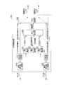
- FIG. 2 is a block diagram showing a functional configuration of the output adjustment device 30.
- the output adjusting device 30 includes an optical signal branching unit 311 for existing broadcasting and a light receiving level measuring unit 312, an optical signal branching unit 321 for new 4K/8K satellite broadcasting, and a light receiving level measuring unit 322.
- the configuration table storage unit 330, the output level calculation unit 340, and the output level adjustment unit 350 are included.
- the optical signal branching unit 311 (first acquisition unit) acquires the optical signal of the wavelength ⁇ 1 for existing broadcasting, which is transmitted from the relay amplifier 13.
- the optical signal branching unit 311 outputs the acquired optical signal to the received light level measuring unit 312 and the output level adjusting unit 350, respectively.
- the optical signal branching unit 311 is configured to include an optical coupler, for example.
- the light reception level measuring unit 312 (first measuring unit) acquires the optical signal of wavelength ⁇ 1 for existing broadcasting, which is output from the optical signal branching unit 311.
- the light receiving level measuring unit 312 measures the light receiving level of the acquired optical signal. Then, the received light level measurement unit 312 outputs information indicating the measurement result to the output level calculation unit 340.
- the optical signal branching unit 321 (second acquisition unit) acquires the optical signal of wavelength ⁇ 2 for the new 4K/8K satellite broadcasting, which is transmitted from the relay amplifier 23.
- the optical signal branching unit 321 outputs the acquired optical signal to the received light level measuring unit 322 and the output level adjusting unit 350, respectively.
- the optical signal branching unit 321 is configured to include an optical coupler, for example.
- the light receiving level measuring unit 322 acquires the optical signal of wavelength ⁇ 2 for the new 4K/8K satellite broadcasting, which is output from the optical signal branching unit 321.
- the received light level measuring unit 322 measures the received light level of the acquired optical signal. Then, the received light level measurement unit 322 outputs information indicating the measurement result to the output level calculation unit 340.
- the setting table storage unit 330 stores a setting table.
- the setting table storage unit 330 is, for example, a storage medium such as a RAM (RandomAccessMemory; readable/writable memory), a flash memory, an EEPROM (ElectricallyErasableProgrammableReadOnlyMemory), and an HDD (HardDiskDrive), or these storages. It is composed of any combination of media.
- the setting table is information including parameter values of various parameters required for output level adjustment (calculation and determination of adjustment amount).
- the above-mentioned various parameters include, for example, the following parameters (A) to (E).
- the setting can be performed via an external control device (not shown) connected to the output adjusting device 30. It may be configured to be performed.
- a control frame for instructing the setting of the parameter value in the setting table is defined in advance, and the control frame is set by being transmitted from the higher-level network device to the output adjustment device 30 via the transmission path. May be configured to be performed.
- an FTTH CATV system using optical signals of two types of wavelengths (wavelength ⁇ 1 and wavelength ⁇ 2) is assumed, and therefore the parameters (B) to (E) are Parameter values for the optical signal of ⁇ 1 and the optical signal of wavelength ⁇ 2 are set in the setting table. Therefore, in the case of an FTTH type CATV system that uses optical signals of three or more types of wavelengths, it is desirable that each parameter value of the optical signals of these three types of wavelengths be set in the setting table.
- the output level calculation unit 340 acquires the information output from the light reception level measurement unit 312, which indicates the measurement result of the light reception level of the optical signal of the wavelength ⁇ 1 for existing broadcasting. Further, the output level calculation unit 340 acquires information indicating the light reception level measurement result of the optical signal of the wavelength ⁇ 2 for the new 4K/8K satellite broadcast, which is output from the light reception level measurement unit 322. Further, the output level calculation unit 340 acquires the parameter value set in the setting table stored in the setting table storage unit 330.
- the output level calculation unit 340 is based on the information indicating the measurement result acquired from the light reception level measurement unit 312, the information indicating the measurement result acquired from the light reception level measurement unit 322, and the parameter value acquired from the setting table storage unit 330. Then, the adjustment amount related to the output level of the optical signal of wavelength ⁇ 1 and the adjustment amount related to the output level of the optical signal of wavelength ⁇ 2 are calculated. The method of calculating the adjustment amount will be described later.
- the output level calculation unit 340 outputs information indicating the calculation results of the adjustment amounts for the output levels of the optical signal of wavelength ⁇ 1 and the optical signal of wavelength ⁇ 2 to the output level adjustment unit 350.
- the output level adjusting unit 350 (signal strength adjusting unit) obtains the information output from the output level calculating unit 340 and indicating the calculation result of each adjustment amount regarding the output level of the optical signal of wavelength ⁇ 1 and the optical signal of wavelength ⁇ 2. To do. As a result, the output level adjusting unit 350 recognizes the adjustment amount for the output level of the optical signal of wavelength ⁇ 1 and the adjustment amount for the output level of the optical signal of wavelength ⁇ 2.
- the output level adjusting unit 350 acquires the optical signal of the wavelength ⁇ 1 for existing broadcasting, which is output from the optical signal branching unit 311 and outputs the acquired optical signal to the WDM filter 40.
- the output level adjusting unit 350 performs adjustment for amplifying or attenuating the output level of the optical signal of the wavelength ⁇ 1 output to the WDM filter 40 according to the recognized adjustment amount.
- the output level adjusting unit 350 acquires the optical signal of the wavelength ⁇ 2 for the new 4K/8K satellite broadcasting output from the optical signal branching unit 321, and outputs the acquired optical signal to the WDM filter 40.
- the output level adjustment unit 350 performs adjustment for amplifying or attenuating the output level of the optical signal of the wavelength ⁇ 2 output to the WDM filter 40 according to the recognized adjustment amount.
- Adjustment amount calculation procedure Forinafter, an example of a procedure of calculating the adjustment amount of the output level of the optical signal, which is performed by the output level calculation unit 340, will be described.
- the output level calculation unit 340 performs calculation according to the following procedures 1 to 4.
- the output level calculation unit 340 has the minimum light receiving sensitivity of the optical signal of the wavelength ⁇ 1 in the optical receiving unit 61 when the light receiving level of the optical signal of the wavelength ⁇ 1 is in the optical receiving unit 61.
- the required output level (first required signal strength) of the optical signal of wavelength ⁇ 1 in the access amplifier 50 which is necessary to achieve the above, is calculated. Further, the output level calculation unit 340 is necessary so that the light receiving level of the optical signal of the wavelength ⁇ 2 in the optical receiving unit 62 becomes equal to or higher than the minimum light receiving sensitivity of the optical signal of the wavelength ⁇ 2 of the optical receiving unit 62.
- the required output level (second required signal strength) of the optical signal of wavelength ⁇ 2 in the access amplifier 50 is calculated.
- the output level calculation unit 340 calculates the minimum value of each optical receiving unit (optical receiving unit 61 and optical receiving unit 62) based on the parameter values of the parameters (B) and (C) set in the setting table.
- Each required output level is calculated in consideration of the light receiving sensitivity and the transmission loss according to the distance between the access amplifier 50 and each light receiving unit.
- the output level calculator 340 outputs the output level of the optical signal (multiplexed signal) output from the access amplifier 50 (that is, the output level of the optical signal of wavelength ⁇ 1 and The sum of the output level of the optical signal of the wavelength ⁇ 2) is equal to the parameter value of the parameter (A) set in the above setting table (here, Z [mW (milliwatt)]).
- the output level calculation unit 340 determines that the output level of the optical signal of the wavelength ⁇ 1 is equal to or higher than the required output level of the optical signal of the wavelength ⁇ 1 calculated in the above procedure 1 and the output level of the optical signal of the wavelength ⁇ 2.
- the respective output levels (output signal intensities) are determined so as to satisfy the condition that is equal to or higher than the required output level of the optical signal of wavelength ⁇ 2 calculated by the above procedure 1.
- X and Y values there can be innumerable combinations of X and Y values that satisfy the above conditions.
- the required output level (here, X′ [mW]) of the optical signal of the wavelength ⁇ 1 calculated in the procedure 1 and the light of the wavelength ⁇ 2 are used.
- a method of deciding the values of X and Y so that the ratio of the signal to the required output level (here, Y′ [mW]) and the ratio of the value of X and the value of Y coincide with each other. can be used.
- the values of X and Y are determined by the following equation (1).
- the value of Y is set to Y′ which is the required output level of the optical signal of wavelength ⁇ 2
- a method of determining the value calculated by' may be used. In this latter determination method, since only the minimum output level (that is, the required output level) is assigned to the output level of the optical signal of wavelength ⁇ 2, the output level of the optical signal of wavelength ⁇ 1 is relatively set. More power levels are allocated.
- the optical signal of wavelength ⁇ 2 is input in the network configuration (FIG. 1) in this embodiment, it is output from the access amplifier 50 as compared with the case of the conventional network configuration (FIG. 7).
- the output level of the optical signal of wavelength ⁇ 1 in the output level of the multiplexed signal inevitably decreases.
- the conventional network configuration is expanded to the network configuration of this embodiment (that is, when the new 4K/8K satellite broadcasting is supported)
- the conventional network configuration can be viewed.
- some viewers may not be able to view the existing broadcast. It should be noted that such viewers are more likely to occur in distant viewers who are particularly affected by signal attenuation.
- the output level of the optical signal of the wavelength ⁇ 1 is made higher in the output level of the combined signal output from the access amplifier 50 (that is, the combined signal It is necessary to bring it closer to the output level value). Therefore, it can be said that the latter determination method is effective for suppressing the occurrence of the viewer as described above.
- the output level calculation unit 340 respectively determines the input levels of the optical signal of wavelength ⁇ 1 and the optical signal of wavelength ⁇ 2 included in the multiplexed signal input to the access amplifier 50. decide. At this time, the output level calculation unit 340 controls the output levels of the optical signal of the wavelength ⁇ 1 and the optical signal of the wavelength ⁇ 2 output from the access amplifier 50 to be the X and Y values determined by the procedure 2, respectively. , And determines the input level (input signal strength) of the optical signal of wavelength ⁇ 1 and the optical signal of wavelength ⁇ 2 input to the access amplifier 50, respectively.
- the output level calculation unit 340 calculates The values of x and y may be determined so as to satisfy the expression (2).
- the output level calculator 340 matches the input level of the optical signal of the wavelength ⁇ 1 and the optical signal of the wavelength ⁇ 2 so as to match the ratio between the output level of the optical signal of the wavelength ⁇ 1 and the output level of the optical signal of the wavelength ⁇ 2.
- the output level of the optical signal of wavelength ⁇ 1 and the output level of the optical signal of wavelength ⁇ 2 output from the access amplifier 50 are controlled to desired X and Y values. be able to.
- adjustment processing adjustment processing by amplification or attenuation of the received light signal can be used, but when adjustment by amplification is required, generally, the apparatus configuration is relatively complicated as compared with the attenuation function. It becomes necessary to equip the output adjusting device 30 with a function. Therefore, it is desirable to use a combination of the values of x and y such that the above adjustment processing can be performed only by signal attenuation.
- the output level X of the optical signal of wavelength ⁇ 1 and the light of wavelength ⁇ 2 are used.
- the sum (X+Y) of the signal output level Y satisfies the condition that the parameter value Z of the parameter (A) set in the setting table is satisfied, and the value x+y is the input in the specification for the access amplifier 50.
- a method that minimizes the level can be used.
- the output level calculation unit 340 sets the input level of the optical signal of wavelength ⁇ 1 and the input level of the optical signal of wavelength ⁇ 2 input to the access amplifier 50 to the value of x and y determined by the above procedure 3.
- the output level calculation unit 340 uses the light reception level value of the optical signal of the wavelength ⁇ 1 acquired from the light reception level measurement unit 312, the light reception level value of the wavelength ⁇ 2 acquired from the light reception level measurement unit 322, and the setting table storage.
- Each adjustment amount is calculated using the parameter values of the parameters (D) and (E) acquired from the unit 330.
- the output level calculation unit 340 outputs information indicating the calculated signal level adjustment amount for the wavelength ⁇ 1 optical signal and the calculated signal level adjustment amount for the wavelength ⁇ 2 optical signal to the output level adjustment unit 350.
- the output level calculation unit 340 uses the optical signal of the wavelength ⁇ 1 input to the output level adjustment unit 350 via the optical signal branching unit 311 and the adjustment amount to be applied to the optical signal.
- the adjustment amount to be applied to the optical signal of wavelength ⁇ 2 input to the output level adjusting unit 350 via the signal branching unit 321 can be calculated.
- the optical signals of the wavelengths ⁇ 1 and ⁇ 2 are continuously transmitted from the optical transmitter 12 and the optical transmitter 22 to the FTTH type CATV system 1 for broadcasting.
- the light receiving level of the optical signal of the wavelength ⁇ 1 and the light receiving level of the optical signal of the wavelength ⁇ 2 in the output adjusting device 30 are not always constant, and generally, at least a slight fluctuation of the light receiving level can always occur. .. It is not realistic from the viewpoint of the load on the output adjustment device 30 to recalculate the adjustment amount and control the adjustment processing by the output level adjustment unit 350 each time so as to follow such a minute fluctuation. ..
- the output level calculation unit 340 obtains minute fluctuations in the light reception level of the optical signal of wavelength ⁇ 1 and the light reception level of the optical signal of wavelength ⁇ 2, which are obtained from the light reception level measurement unit 312 and the light reception level measurement unit 322, respectively. Even if it is accompanied by, it is possible to allow some fluctuation as being within the error range and continue the adjustment based on the adjustment amount up to that point (that is, before the fluctuation).
- the value of the amount of fluctuation within the allowable range is set in advance in, for example, a storage medium (not shown) included in the setting table storage unit 330 or the output level calculation unit 340.
- a value of ⁇ P [mW] is preset as the allowable range.
- the output level calculation unit 340 and the light receiving level (here, P1 [mW]) of the light signal of the wavelength ⁇ 1 first notified from the light receiving level measuring unit 312 and the light receiving level measuring unit 322 and the wavelength ⁇ 2.
- the adjustment amount is calculated using the light reception level (here, P2 [mW]) of the optical signal of 1 as the reference level.
- the output level calculation unit 340 considers that the fluctuation is the allowable fluctuation as long as the fluctuation of the received light level for each wavelength remains within the range satisfying “P1 ⁇ P” and “P2 ⁇ P”, and The adjustment amount calculation process is not executed. Then, the output level calculation unit 340 updates the value of the received light level at that time as a new reference level only when the fluctuation of the received light level exceeds the allowable range (that is, updates the values of P1 and P2 described above). However, the adjustment amount may be recalculated using the updated light reception level value.
- the input optical signal of the wavelength ⁇ 1 and the input optical signal of the wavelength ⁇ 2 are respectively adjusted with appropriate signal levels and then output.
- An optical signal having a signal level that provides a desired combination of the values of x and y is input to the access amplifier 50. Then, since the optical signal is input to the access amplifier 50 at a signal level that is a combination of the values of x and y, the optical signal of the wavelength ⁇ 1 and the optical signal of the wavelength ⁇ 2 respectively have the above-mentioned desired X and Y. It is output from the access amplifier 50 at an output level that has a value.
- the optical signal of the wavelength ⁇ 1 and the optical signal of the wavelength ⁇ 2 have a signal level that can be received by each optical receiving unit in the subscriber's house in the desired distribution area. Since it is transmitted reliably, it enables each viewer to watch both existing broadcasts and new 4K/8K satellite broadcasts.
- the WDM filter 40 is provided outside the output adjustment device 30, but the output adjustment device 30 may have the WDM filter 40 built therein.
- a functional unit corresponding to the function of the WDM filter 40 that is, the function of multiplexing the optical signal of wavelength ⁇ 1 and the optical signal of wavelength ⁇ 2 is provided in the subsequent stage of the output level adjusting unit 350 shown in FIG. To be Then, the multiplexed signal multiplexed by the WDM filter 40 is output from the output adjustment device 30 to the access amplifier 50.
- the optical signal of the wavelength ⁇ 1 and the optical signal of the wavelength ⁇ 2 transmitted from the relay amplifier 13 and the relay amplifier 23 shown in FIG. 1 to the output adjusting device 30 are accompanied by signal amplification in the relay amplifier 13 and the relay amplifier 23.
- broadband ASE Amplitude ASE
- the wavelength band to be measured by the light reception level measurement unit 312 and the light reception level measurement unit 322 illustrated in FIG. 2 includes not only the wavelength band of the wavelength ⁇ 1 or the wavelength ⁇ 2 but also the wavelength band around the wavelength band.
- the light reception level measurement unit 312 and the light reception level measurement unit 322 measure the noise level of the wavelength band including only the ASE component by including it in the light reception level of the optical signal of the wavelength ⁇ 1 or the wavelength ⁇ 2. Will be done.
- the light receiving level measuring unit 312 and the light receiving level measuring unit 322 may not be able to accurately measure the signal level of the optical signal of the wavelength ⁇ 1 or the wavelength ⁇ 2.
- the values of the light reception levels of the optical signals of the wavelength ⁇ 1 and the wavelength ⁇ 2 notified to the output level calculation unit 340 shown in FIG. 2 are excessive because the ASE component in the wavelength band other than the wavelength ⁇ 1 and the wavelength ⁇ 2 is included. It becomes a value.
- the output level calculation unit 340 ends up calculating the adjustment amount based on this excess value.
- the output level adjusting unit 350 shown in FIG. 2 outputs a signal to the optical signal of the wavelength ⁇ 1 and the wavelength ⁇ 2 including the ASE component in the wavelength band other than the wavelength ⁇ 1 and the wavelength ⁇ 2 based on the calculated adjustment amount. Adjust the level.
- the ASE component in the adjusted optical signal is removed by the WDM filter 40 shown in FIG.
- a case may occur in which the desired input ratio to the access amplifier 50 is not satisfied (that is, the above expression (2) is not satisfied).
- the wavelength bands other than the wavelength ⁇ 1 and the wavelength ⁇ 2 are previously measured. Noise (ASE component) is removed.
- FIG. 3 is a block diagram showing a functional configuration of the output adjusting device 30b.
- the functional configuration of the output adjustment device 30b further includes a noise removal unit 310 and a noise removal unit 320 in addition to the functional configuration of the output adjustment device 30 according to the first embodiment shown in FIG. The difference is that.
- the functions of the other functional blocks included in the output adjusting device 30b are the same as those of the functional blocks included in the output adjusting device 30, and therefore, the same reference numerals are given and the description thereof is omitted. ..
- the noise removing unit 310 and the noise removing unit 320 are configured to include a filter circuit such as a bandpass filter that can pass only an optical signal in a desired frequency band and remove an optical signal in another frequency band. It
- the noise eliminator 310 (first filter) allows only the optical signal of wavelength ⁇ 1 to pass through the optical signal for existing broadcasting sent from the relay amplifier 13 and causes noise (ASE component) in a frequency band other than wavelength ⁇ 1. ) Is removed. As a result, the optical signal from which the ASE component has been removed by the noise removing unit 310 is input to the optical signal branching unit 311. Further, the noise removing unit 320 (second filter) allows only the optical signal of the wavelength ⁇ 2 to pass through the optical signal for the new 4K/8K satellite broadcast transmitted from the relay amplifier 23, and outputs the frequency other than the wavelength ⁇ 2. Band noise (ASE component) is removed. As a result, the optical signal from which the ASE component has been removed by the noise removing unit 320 is input to the optical signal branching unit 321.
- the output adjusting device 30b includes the noise removing unit 310 and the noise removing unit 320, so that the optical signals of the wavelength ⁇ 1 and the wavelength ⁇ 2 from which the noise (ASE component) in the unnecessary wavelength band is removed, respectively. It is input to the optical signal branching unit 311 and the optical signal branching unit 321. As a result, the light receiving level measuring unit 312 and the light receiving level measuring unit 322 can measure the light receiving level more accurately, and the output level calculation unit 340 can calculate a more appropriate adjustment amount, and the output level adjustment. The section 350 can make more appropriate adjustments.
- the output adjustment device 30b is configured to include the noise removing unit 310 and the noise removing unit 320, but the present invention is not limited to this.
- a filter circuit such as a bandpass filter may be provided outside the output adjustment device 30b.
- filter circuits are installed between the relay amplifier 13 and the output adjusting device 30b, and between the relay amplifier 23 and the output adjusting device 30b.
- the third embodiment of the present invention will be described below.
- the network configuration shown in FIG. 8 is assumed as a network configuration for realizing distribution and viewing of new 4K/8K satellite broadcasts in addition to existing broadcasts. did.
- the output adjusting device 30 and the output adjusting device 30b for solving the above problems in the network configuration have been described. Even if the existing relay amplifier 13 does not support the new 4K/8K satellite broadcasting (that is, does not support the optical signal of wavelength ⁇ 2), the network configuration shown in FIG. In addition to existing broadcasts, this network configuration enables the delivery and viewing of new 4K/8K satellite broadcasts.
- the existing relay amplifier is compatible with both the optical signal of wavelength ⁇ 1 and the optical signal of wavelength ⁇ 2, and both optical signals have the desired signal level in the existing optical transmission line. It is assumed that the network configuration can reach the access amplifier. Then, an FTTH type CATV system that enables realization of distribution and viewing of new 4K/8K satellite broadcasting in addition to existing broadcasting in the network configuration will be described.
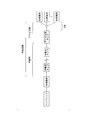
- FIG. 4 is a block diagram showing an example of a network configuration assumed in this embodiment.
- the relay amplifier supports both the optical signal of wavelength ⁇ 1 and the optical signal of wavelength ⁇ 2.
- a WDM filter can be installed at the position.
- the optical signal (combined signal) multiplexed by the WDM filter is input to the relay amplifier.
- FIG. 5 is a block diagram showing an example of the network configuration. Similar to the first and second embodiments described above, the output adjustment device 30c is installed in the preceding stage of the access amplifier 50. However, as shown in FIG. 5, in the present embodiment, a combined signal obtained by combining the optical signal of wavelength ⁇ 1 and the optical signal of wavelength ⁇ 2 in the relay NW is transmitted to the output adjustment device 30c. Therefore, the optical signals input/output to/from the output adjustment device 30c are all combined signals obtained by combining the optical signal of wavelength ⁇ 1 and the optical signal of wavelength ⁇ 2.
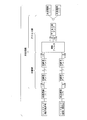
- FIG. 6 is a block diagram showing a functional configuration of the output adjusting device 30c.
- the functional configuration of the output adjusting device 30c further includes a separating unit 300 and a multiplexing unit 360 in addition to the functional configuration of the output adjusting device 30 according to the first embodiment shown in FIG. Differ in that there is.
- the functions of the other functional blocks included in the output adjustment device 30c are the same as the functions of the individual functional blocks included in the output adjustment device 30, and thus the same reference numerals are given and the description thereof is omitted. ..
- the separation unit 300 is configured to include a filter circuit such as a WDM filter that can separate an optical signal.
- the demultiplexing unit 300 demultiplexes the multiplexed signal sent from the relay amplifier 13c into an optical signal of wavelength ⁇ 1 and an optical signal of wavelength ⁇ 2. Then, the demultiplexing unit 300 sends the optical signal of wavelength ⁇ 1 to the optical signal branching unit 311 and sends the optical signal of wavelength ⁇ 2 to the optical signal branching unit 321.
- the multiplexing unit 360 is configured to include a filter circuit capable of multiplexing optical signals, such as a WDM filter.
- the multiplexing unit 360 multiplexes the adjusted optical signal of the wavelength ⁇ 1 and the adjusted optical signal of the wavelength ⁇ 2 sent from the output level adjusting unit 350. Then, the multiplexing unit 360 sends the multiplexed signal to the access amplifier 50.
- the output adjusting device 30c first separates the input combined signal into the optical signal of the wavelength ⁇ 1 and the optical signal of the wavelength ⁇ 2 by the separating unit 300 (for example, the WDM filter). The output adjusting device 30c respectively adjusts the signal levels of the two separated optical signals. Then, the output adjusting apparatus 30c multiplexes the adjusted optical signals again by the multiplexing unit 360 (for example, a WDM filter), and outputs the multiplexed signal.
- the multiplexing unit 360 for example, a WDM filter
- the FTTH type CATV system acquires the optical signal of wavelength ⁇ 1 and the optical signal of wavelength ⁇ 2, adjusts the signal levels of both optical signals, and outputs the output. Equipped with a device.
- the output adjusting device grasps the desired output level of each of the optical signal of wavelength ⁇ 1 and the optical signal of wavelength ⁇ 2 to be output from the access amplifier. Then, the output adjusting device sets the wavelength ⁇ 1 and the wavelength to the access amplifier so that the output level of the optical signal of the wavelength ⁇ 1 and the output level of the optical signal of the wavelength ⁇ 2 in the access amplifier respectively become the desired output levels.
- Each of the desired input levels of the optical signal of ⁇ 2 is determined.
- the output adjusting device monitors the signal levels of the optical signals of wavelength ⁇ 1 and wavelength ⁇ 2 from the relay amplifier so that the input level of the optical signal input to the access amplifier becomes the desired input level. , Adjusts the signal level as necessary, and outputs the optical signal to the access amplifier.
- the access amplifier has a fixed level in which the optical signals of the wavelength ⁇ 1 and the wavelength ⁇ 2 having the desired output levels are combined. It is possible to output an optical signal (combined signal) having a total output level of. Since the desired output level of each of the optical signals of wavelength ⁇ 1 and wavelength ⁇ 2 is controlled to be a sufficient output level for appropriately receiving each optical signal in the optical receiver of the subscriber's house. The viewer can surely watch both the existing broadcast and the new 4K/8K satellite broadcast.
- the present invention it is assumed that a new 4K/8K satellite broadcast optical signal (having a wavelength ⁇ 2) is newly input to the existing access amplifier. Therefore, as described above, it is unavoidable that the output level of the optical signal of the wavelength ⁇ 1 output from the access amplifier is lower than that in the conventional case (that is, when only the existing broadcast is viewed). Therefore, the present invention is premised on that the output level of the optical signal of the wavelength ⁇ 1 is lower than that of the conventional one, regardless of the presence or absence of the adjustment by the output adjusting device.
- a part or all of the setting table storage unit 330 and the output level calculation unit 340 included in the output adjustment device 30 (30b, 30c) in the above-described embodiment may be realized by a computer.
- the program for realizing this function may be recorded in a computer-readable recording medium, and the program recorded in this recording medium may be read by a computer system and executed.
- the “computer system” mentioned here includes an OS and hardware such as peripheral devices.
- the “computer-readable recording medium” refers to a portable medium such as a flexible disk, a magneto-optical disk, a ROM, a CD-ROM, or a storage device such as a hard disk built in a computer system.
- the "computer-readable recording medium” means to hold a program dynamically for a short time like a communication line when transmitting the program through a network such as the Internet or a communication line such as a telephone line.
- a volatile memory inside a computer system that serves as a server or a client in that case may hold a program for a certain period of time.
- the program may be for realizing some of the functions described above, or may be one that can realize the functions described above in combination with a program already recorded in a computer system, It may be realized using hardware such as PLD (Programmable Logic Device) and FPGA (Field Programmable Gate Array).
Landscapes
- Engineering & Computer Science (AREA)
- Physics & Mathematics (AREA)
- Electromagnetism (AREA)
- Computer Networks & Wireless Communication (AREA)
- Signal Processing (AREA)
- Multimedia (AREA)
- Optical Communication System (AREA)
Abstract
光伝送システムは、第1の波長を有する第1の光信号を送信する第1の光送信部と、第2の波長を有する第2の光信号を送信する第2の光送信部と、第1の光信号及び第2の光信号を取得し、各光信号の信号強度をそれぞれ調整して出力する出力調整部と、信号強度が調整された第1の光信号と第2の光信号とを合波し合波信号を出力する合波器と、合波信号を増幅する増幅器と、増幅された第1の光信号を受信する第1の光受信部と、増幅された第2の光信号を受信する第2の光受信部とを備え、出力調整部は、第1の光受信部で受信される第1の光信号の信号強度が第1の所定値以上、かつ第2の光受信部で受信される前2の光信号の信号強度が第2の所定値以上となるように第1の光信号及び第2の光信号の信号強度を調整する。
Description
本発明は、光伝送システム、及び出力調整装置に関する。
加入者宅へ映像を配信するネットワークシステムとして、例えばFTTH(Fiber to the Home)型CATV(Cable television;ケーブルテレビ)システムが知られている。
図7に、従来のFTTH型CATVシステムのネットワーク構成の一例を示す。図7に示すように、従来のFTTH型CATVシステムは、例えば、ヘッドエンドと、光送信部と、中継用アンプと、アクセス用アンプと、各々の加入者宅等に設置される光受信部と、を含んで構成される。
図7に、従来のFTTH型CATVシステムのネットワーク構成の一例を示す。図7に示すように、従来のFTTH型CATVシステムは、例えば、ヘッドエンドと、光送信部と、中継用アンプと、アクセス用アンプと、各々の加入者宅等に設置される光受信部と、を含んで構成される。
ヘッドエンドは、放送局から送信される映像信号を乗せた電波を地上の送信塔や人工衛星等を介して受信し、受信した電波に対して増幅等の調整を行う。そして、ヘッドエンドは、当該映像信号に基づく電気信号を光送信部へ出力する。光送信部は、取得した電気信号を光信号に変換し、当該光信号を光ファイバで構築された光伝送路へ送出する。光伝送路は、中継ネットワーク(以下、「中継NW」という。)の区間とアクセスネットワーク(以下、「アクセスNW」という。)の区間とに分けられる。中継NWは、光送信部とアクセスNWとの間をつなぐ通信ネットワークである。中継NWでは、伝送距離が長距離に及ぶ場合等において、増幅器(以下、「中継用アンプ」という。)が多段構成される。各々の中継用アンプは、増幅した光信号を、後段の他の中継用アンプへ送出したり、アクセスNW区間内の機器へ送出したり、あるいは、光カプラによって光信号を分岐させて後段の他の中継用アンプ及びアクセスNW区間内の機器の双方へ送出したりする。一方、アクセスNWは、中継NWと光信号を終端する各光受信部との間をつなぐ通信ネットワークである。アクセスNWでは、中継NWから出力された光信号を複数の加入者宅に設置された光受信部へ分配するために、一般的に、PON(Passive Optical Network;受動光ネットワーク)構成が適用される。更に、図7に示すように、PON構成による光信号の分配に伴う損失及び中継用アンプによる光信号の分岐に伴う損失等の補償を目的として、アクセスNWにおいても増幅器(以下、「アクセス用アンプ」という。)が用いられる場合がある。
上記のようなネットワーク構成を有する従来のFTTH型CATVシステムでは、光伝送方式として、例えばFM(Frequency Modulation;周波数変調)一括変換方式が用いられる(非特許文献1参照)。光送信部は、ヘッドエンドから出力された、周波数多重された多チャンネル映像の電気信号を受信し、当該電気信号を一括して1チャンネルの広帯域なFM信号に変換する。更に、光送信部は、変換されたFM信号を、強度変調によって一つの波長λからなる光信号に変換し、光伝送路へ送出する。一方、光受信部は、この波長λの光信号を受光すると、当該光信号を、電気信号への変換により広帯域FM信号に変換し、復調する。これにより、光受信部は、受光した光信号から、周波数多重された多チャンネル映像の電気信号を取り出すことができる。
従来、本国においては、上記のようなネットワーク構成及び光伝送方式によって、多チャンネルの映像配信が実現されている。配信される映像としては、右旋円偏波を用いて人工衛星から地上へ配信されるBS(Broadcasting Satellites)放送及び110度CS(Communication Satellites)放送のほか、地上デジタル放送等がある。更に、2018年12月から、左旋円偏波を用いて人工衛星から地上へ配信されるBS放送(中間周波数:2224~2681[MHz(メガヘルツ)])と110度CS放送(中間周波数:2748~3224[MHz])とが、新4K・8K衛星放送として開始されている。この新4K・8K衛星放送で使用される中間周波数帯は、既存放送で使用されている中間周波数帯とは異なる。そのため、既存の放送設備が新4K・8K衛星放送の中間周波数に対応していない場合等において、既存の放送設備のみでは新4K・8K衛星放送の配信及び視聴を実現することができない。
これに対し、既存放送の配信及び視聴に加えて更に新4K・8K衛星放送の配信及び視聴を実現する方法の一つとして、新4K・8K衛星放送に対応した中継NW及びその上位設備を、既存放送用の設備とは別に設置する方法が考えられる。図8に、この方法を用いた場合におけるネットワーク構成の一例を示す。図8に示すように、このネットワーク構成では、図7に示したネットワーク構成に加えて、新4K・8K衛星放送に対応したヘッドエンド、光送信部、中継用アンプ、及びWDM(Wavelength Division Multiplexing;波長分割多重)フィルタが新たに設置される。WDMフィルタは、既存放送用の中継用アンプから出力された光信号と新4K・8K衛星放送に対応した中継用アンプから出力された光信号とを合波し、合波された光信号(以下、「合波信号」という。)を既存のアクセス用アンプへ送出する。ここで、既存放送用の中継用アンプから出力された出力光の波長を波長λ1、及び、新4K・8K衛星放送に対応した中継用アンプから出力された出力光の波長を波長λ2とし、波長λ1と波長λ2とは互いに異なる波長であるものとする。このとき、既存放送用の光受信部は、波長λ1の光信号を受光することはできるが、波長λ2の光信号は受光することができない場合がある。このような場合において視聴者による新4K・8K衛星放送の視聴を可能にするためには、波長λ2の光信号を受光することができる光受信部を新たに設置する必要がある。なお、新たに設置される光受信部として、波長λ2の光信号だけでなく波長λ1の光信号も受光することができる光受信部が用いられるならば、視聴者は新たに設置された光受信部のみで、既存放送と新4K・8K衛星放送との双方の放送を視聴することができる。また、上記のネットワーク構成によれば、既存放送用のネットワーク設備を流用することができるため、新4K・8K衛星放送の配信及び視聴を実現するために必要となる機器の設置コストを抑制することができる。
ところで、光通信において用いられる一般的な増幅器として、例えばEDFA(Erbium-Doped Fiber Amplifier;エルビウム添加ファイバ増幅器)等の光ファイバ増幅器がある。この光ファイバ増幅器は、例えば図8に示すネットワーク構成におけるアクセス用アンプのように複数の波長の光信号が入力される場合であっても、一括して光信号のまま増幅することができるという特徴がある。また、APC(Automatic Power Control;自動パワー制御)機能が搭載された光ファイバ増幅器は、当該光ファイバ増幅器への光信号の入力レベルが変動する場合であっても、変動が許容範囲であるならば光信号の出力レベルを一定に保つように制御することができる。但し、当該APC機能は、入力される光信号が波長の異なる複数の光信号の合波信号であっても、当該合波信号に対する出力レベルを一定にするように制御するだけである。すなわち、例えば図8に示すように、アクセス用アンプへ入力される光信号が波長λ1の光信号と波長λ2の光信号との合波信号である場合、APC機能は、あくまで当該合波信号の出力レベルを一定にする制御を行うだけであって、波長λ1の光信号の出力レベルと波長λ2の光信号の出力レベルとをそれぞれ一定にする制御を行うわけではない。
上述したように図8に示す新4K・8K衛星放送に対応したネットワーク構成では、図7に示す既存放送用のネットワーク構成におけるアクセス用アンプを流用することが想定されていることから、図8に示すアクセス用アンプから出力される合波信号の出力レベルと、図7のアクセス用アンプから出力される光信号の出力レベルとは、同等である。また、図8に示すネットワーク構成では、アクセス用アンプの上位設備についても図7に示すネットワーク構成におけるネットワーク設備を流用することが想定されていることから、図8に示すネットワーク構成におけるアクセス用アンプへ入力される合波信号の入力レベルのうち波長λ1の光信号分に相当する入力レベルと、図7に示すネットワーク構成におけるアクセス用アンプへ入力される波長λ1の光信号の入力レベルとは、同等である。これにより、図8のネットワーク構成におけるアクセス用アンプから出力される光信号(合波信号)の出力レベルのうち波長λ1の(既存放送用の)光信号分に相当する出力レベルは、図7に示すネットワーク構成におけるアクセス用アンプから出力される(既存放送用の)光信号の出力レベルと比べて必然的に小さな値になってしまう。
また、図8に示すネットワーク構成におけるアクセス用アンプへ入力される合波信号の入力レベルに含まれる波長λ1の光信号分の入力レベル、及び波長λ2の光信号分の入力レベルは、常に一定であるとは限らず、時間的にそれぞれ変動する場合がある。このように双方の入力レベルが変動したとしても、双方の入力レベルの合計値(すなわち、合波信号の入力レベル)がアクセス用アンプの仕様上の許容範囲内であれば、アクセス用アンプは、光信号(合波信号)の出力レベルを一定に保つことはできる。しかしながら、上記の変動に伴って、アクセス用アンプへ入力される合波信号の入力レベルに含まれる、波長λ1の光信号分の入力レベルと波長λ2の光信号分の入力レベルとの比が変動することによって、アクセス用アンプから出力される合波信号に含まれる波長λ1の光信号分の出力レベルと波長λ2の光信号分の出力レベルとの比も同様に変動する。そのため、たとえ双方の光信号の入力レベルの合計値がアクセス用アンプの仕様上の許容範囲内であったとしても、波長λ1の光信号分の出力レベルと波長λ2の光信号分の出力レベルの少なくとも一方が、例えば加入者宅等に設置された光受信部において受信することができない出力レベルにまで低下する可能性がある。
"ITU-T J.185: Transmission equipment for transferring multi-channel television signals over optical access networks by frequency modulationconversion," International Telecommunication Union, June 2012.
このように、APC機能が搭載された既存放送用のアクセス用アンプを流用して図8に示すような新4K・8K衛星放送に対応したネットワーク構成を構築する場合、当該アクセス用アンプから出力される光信号(合波信号)の出力レベルに含まれる波長λ1の光信号分の出力レベル及び波長λ2の光信号分の出力レベルの少なくとも一方が、所望の出力レベルに満たなくなる場合が生じうる。これは、上述したように、当該アクセス用アンプに対して新たに波長λ2の(新4K・8K衛星放送用の)光信号の入力が追加されること、及び、当該アクセス用アンプへ入力される合波信号の入力レベルに含まれる波長λ1の光信号分の入力レベル及び波長λ2の光信号分の入力レベルがそれぞれ変動しうることに起因する。これにより、例えば各々の加入者宅等に設置された光受信部において、波長λ1の光信号の受信レベルと波長λ2の光信号の受信レベルとの少なくとも一方が視聴可能な受信レベルに達しなくなり、視聴者が所望の映像を視聴することができない場合が生じるという課題がある。
本発明は、上記のような技術的背景に鑑みてなされたものであり、設置コストを抑えつつ、既存放送及び新規追加された放送の視聴を可能にする技術を提供することを目的とする。
本発明の一態様は、第1の波長を有する第1の光信号を送信する第1の光送信部と、前記第1の波長とは異なる第2の波長を有する第2の光信号を送信する第2の光送信部と、前記第1の光信号及び前記第2の光信号を取得し、取得した各光信号の信号強度をそれぞれ調整して出力する出力調整部と、前記出力調整部で信号強度がそれぞれ調整された前記第1の光信号と前記第2の光信号とを合波し、合波信号を出力する合波器と、前記合波信号を増幅する増幅器と、前記増幅器で増幅された前記合波信号に含まれる前記第1の光信号を受信する第1の光受信部と、前記増幅器で増幅された前記合波信号に含まれる前記第2の光信号を受信する第2の光受信部と、を備え、前記出力調整部は、前記第1の光受信部によって受信される前記第1の光信号の信号強度が第1の所定値以上となり、かつ、前記第2の光受信部によって受信される前記第2の光信号の信号強度が第2の所定値以上となるように、取得した前記第1の光信号及び前記第2の光信号の信号強度をそれぞれ調整する光伝送システムである。
また、本発明の一態様は、上記の光伝送システムであって、前記出力調整部は、前記増幅器から出力される前記合波信号の信号強度が第3の所定値となるように、前記第1の光信号及び前記第2の光信号の信号強度をそれぞれ調整する。
また、本発明の一態様は、上記の光伝送システムであって、前記出力調整部は、前記合波器において生じる挿入損失、及び前記増幅器と前記第1の光受信部及び前記第2の光受信部との間において生じる伝送損失に基づいて、前記第1の光信号及び前記第2の光信号の信号強度をそれぞれ調整する。
また、本発明の一態様は、上記の光伝送システムであって、前記第1の波長のみを通過させる第1のフィルタと、前記第2の波長のみを通過させる第2のフィルタと、を更に備え、前記出力調整部は、前記第1のフィルタを通過した前記第1の光信号及び前記第2のフィルタを通過した前記第2の光信号を取得し、取得した各光信号の信号強度をそれぞれ調整して出力する。
また、本発明の一態様は、上記の光伝送システムであって、前記第1の光送信部から送信された前記第1の光信号と前記第2の光送信部から送信された前記第2の光信号とを合波する第2の合波器を更に備え、前記出力調整部は、前記第2の合波器で合波された光信号を取得し、取得した光信号を前記第1の光信号と前記第2の光信号とに分離し、分離した前記第1の光信号及び前記第2の光信号の信号強度をそれぞれ調整して出力する。
また、本発明の一態様は、上記の光伝送システムであって、前記出力調整部は、前記第1の所定値、前記合波器において生じる挿入損失、及び前記増幅器と前記第1の光受信部との間において生じる伝送損失に基づいて、前記増幅器から出力される前記合波信号に含まれる前記第1の光信号に必要とされる信号強度である第1の所要信号強度を算出し、前記第2の所定値、前記合波器において生じる挿入損失、及び前記増幅器と前記第2の光受信部との間において生じる伝送損失に基づいて、前記増幅器から出力される前記合波信号に含まれる前記第2の光信号に必要とされる信号強度である第2の所要信号強度を算出し、前記第1の所要信号強度と前記第2の所要信号強度とをそれぞれ満たすように、前記増幅器から出力される前記合波信号に含まれる前記第1の光信号及び前記第2の光信号それぞれの出力信号強度を算出し、算出されたそれぞれの前記出力信号強度になるために必要とされる、前記増幅器に入力される前記合波信号に含まれる前記第1の光信号及び前記第2の光信号のそれぞれの入力信号強度を算出し、取得した前記第1の光信号及び前記第2の光信号の信号強度の測定結果と、算出されたそれぞれの前記入力信号強度とに基づいて、取得した前記第1の光信号及び前記第2の光信号のそれぞれに対する信号強度の調整量を算出する。
また、本発明の一態様は、第1の光受信部及び第2の光受信部へそれぞれ送信される第1の波長を有する第1の光信号及び前記第1の波長とは異なる第2の波長を有する第2の光信号を増幅する増幅器に入力される合波信号に含まれる、前記第1の光信号及び前記第2の光信号それぞれの信号強度を調整する出力調整装置であって、前記第1の光信号を取得する第1の取得部と、前記第2の光信号を取得する第2の取得部と、前記第1の取得部によって取得された前記第1の光信号の信号強度を測定する第1の測定部と、前記第2の取得部によって取得された前記第2の光信号の信号強度を測定する第2の測定部と、前記第1の測定部による測定の測定結果及び前記第2の測定部による測定の測定結果に基づいて、前記第1の光受信部によって受信される前記第1の光信号の信号強度が第1の所定値以上となり、かつ、前記第2の光受信部によって受信される前記第2の光信号の信号強度が第2の所定値以上となり、かつ、前記増幅器から出力される合波信号の信号強度が第3の所定値となるように、前記第1の取得部によって取得された前記第1の光信号の信号強度及び前記第2の取得部によって取得された前記第2の光信号の信号強度に対するそれぞれの調整量を計算する調整量計算部と、前記調整量計算部によって計算されたそれぞれの前記調整量に基づいて、前記第1の取得部によって取得された前記第1の光信号の信号強度と、前記第2の取得部によって取得された前記第2の光信号の信号強度とを調整し、前記信号強度が調整された前記第1の光信号及び前記第2の光信号を出力する信号強度調整部と、を備える出力調整装置である。
本発明により、設置コストを抑えつつ、既存放送及び新規追加された放送の視聴を可能にする技術を提供することができる。
<第1の実施形態>
以下、本発明の第1の実施形態について、図面を参照しながら説明する。
以下、本発明の第1の実施形態について、図面を参照しながら説明する。
[ネットワーク構成]
以下、本発明の第1の実施形態に係る、新4K・8K衛星放送に対応したFTTH型CATVシステム1のネットワーク構成について説明する。図1は、当該ネットワーク構成の一例を示すブロック図である。図1に示すように、FTTH型CATVシステム1(光伝送システム)は、既存放送用のヘッドエンド11、光送信部12、及び中継用アンプ13と、新4K・8K衛星放送に対応したヘッドエンド21、光送信部22、及び中継用アンプ23と、出力調整装置30と、WDMフィルタ40と、アクセス用アンプ50と、既存放送用の光受信部61と、新4K・8K衛星放送に対応した光受信部62と、を含んで構成される。
以下、本発明の第1の実施形態に係る、新4K・8K衛星放送に対応したFTTH型CATVシステム1のネットワーク構成について説明する。図1は、当該ネットワーク構成の一例を示すブロック図である。図1に示すように、FTTH型CATVシステム1(光伝送システム)は、既存放送用のヘッドエンド11、光送信部12、及び中継用アンプ13と、新4K・8K衛星放送に対応したヘッドエンド21、光送信部22、及び中継用アンプ23と、出力調整装置30と、WDMフィルタ40と、アクセス用アンプ50と、既存放送用の光受信部61と、新4K・8K衛星放送に対応した光受信部62と、を含んで構成される。
ヘッドエンド11は、放送局から送信される既存放送用の映像信号を乗せた電波を地上の送信塔や人工衛星等を介して受信し、受信した電波に対して増幅等の調整を行う。そして、ヘッドエンド11は、当該映像信号に基づく電気信号を光送信部12へ送出する。光送信部12(第1の光送信部)は、受信した電気信号を波長λ1の光信号に変換し、当該光信号を光ファイバで構築された光伝送路70へ送出する。
ヘッドエンド21は、放送局から送信される新4K・8K衛星放送の映像信号を乗せた電波を地上の送信塔や人工衛星等を介して受信し、受信した電波に対して増幅等の調整を行う。そして、ヘッドエンド21は、当該映像信号に基づく電気信号を光送信部22へ送出する。光送信部22(第2の光送信部)は、受信した電気信号を波長λ2の光信号に変換し、当該光信号を光伝送路70へ送出する。ここで、波長λ1と波長λ2とは互いに異なる波長であるものとする。
光伝送路70は、中継NW71の区間とアクセスNW72の区間とに分けられる。中継NW71は、光送信部12及び光送信部22とアクセスNWとの間をそれぞれつなぐ通信ネットワークである。
中継NW71では、既存放送用の中継用アンプ13及び新4K・8K衛星放送用の中継用アンプ23がそれぞれ多段構成される。初段の中継用アンプ13には、光送信部12から送出された波長λ1の光信号が入力される。各々の中継用アンプ13は、増幅した光信号を、後段の他の中継用アンプ13へ送出したり、アクセスNW72の区間内の出力調整装置30へ送出したりする。初段の中継用アンプ23には、光送信部22から送出された波長λ2の光信号が入力される。各々の中継用アンプ23は、増幅した光信号を、後段の他の中継用アンプ23へ送出したり、アクセスNW72の区間内の出力調整装置30へ送出したりする。
一方、アクセスNWでは、一般的に、中継用アンプ13及び中継用アンプ23から受信した光信号を複数の加入者宅へ分配するためにPON構成が適用される。
出力調整装置30(出力調整部)は、中継用アンプ13から送出された波長λ1の光信号と、中継用アンプ23から送出された波長λ2の光信号と、を取得する。出力調整装置30は、取得した双方の光信号の信号レベル(信号強度)を必要に応じてそれぞれ調整し、当該双方の光信号をWDMフィルタ40へそれぞれ調整された出力レベルで出力する。
WDMフィルタ40(合波器)は、出力調整装置30から出力された波長λ1の光信号と波長λ2の光信号とを合波し、合波信号をアクセス用アンプ50へ送出する。
アクセス用アンプ50は、PON構成による光信号の分配に伴う損失の補償等を目的として設置された増幅器である。アクセス用アンプ50は、WDMフィルタ40から送出された光信号(合波信号)を増幅する。そして、アクセス用アンプ50は、増幅された光信号を、当該アクセス用アンプ50の後段に構築されたPONを介して光受信部61及び光受信部62へ送出する。光受信部61及び光受信部62は、例えば各々の加入者宅等に設置され、それぞれ波長λ1及び波長λ2の光信号を終端する。
光受信部61(第1の光受信部)は、既存放送用の中継用アンプ13から出力された波長λ1(第1の波長)の光信号(第1の光信号)を受信することができる。また、光受信部62(第2の光受信部)は、新4K・8K衛星放送に対応した中継用アンプ23から出力された波長λ2(第2の波長)の光信号(第2の光信号)を受信することができる。なお、図1においては、図面を見易くするため、光受信部61と光受信部62とをそれぞれ1つずつ図示しているが、実際には光受信部61及び光受信部62のうち少なくとも一方が複数の加入者宅にそれぞれ設置されている。
[出力調整装置の機能構成]
以下、本発明の第1の実施形態に係るFTTH型CATVシステム1の出力調整装置30の機能構成について説明する。図2は、出力調整装置30の機能構成を示すブロック図である。図2に示すように、出力調整装置30は、既存放送用の光信号分岐部311及び受光レベル測定部312と、新4K・8K衛星放送用の光信号分岐部321及び受光レベル測定部322と、設定テーブル記憶部330と、出力レベル計算部340と、出力レベル調整部350と、を含んで構成される。
以下、本発明の第1の実施形態に係るFTTH型CATVシステム1の出力調整装置30の機能構成について説明する。図2は、出力調整装置30の機能構成を示すブロック図である。図2に示すように、出力調整装置30は、既存放送用の光信号分岐部311及び受光レベル測定部312と、新4K・8K衛星放送用の光信号分岐部321及び受光レベル測定部322と、設定テーブル記憶部330と、出力レベル計算部340と、出力レベル調整部350と、を含んで構成される。
光信号分岐部311(第1の取得部)は、中継用アンプ13から送出された、既存放送用の波長λ1の光信号を取得する。光信号分岐部311は、取得した光信号を受光レベル測定部312と出力レベル調整部350とへそれぞれ出力する。光信号分岐部311は、例えば光カプラを含んで構成される。
受光レベル測定部312(第1の測定部)は、光信号分岐部311から出力された、既存放送用の波長λ1の光信号を取得する。受光レベル測定部312は、取得した光信号の受光レベルを測定する。そして、受光レベル測定部312は、測定結果を示す情報を出力レベル計算部340へ出力する。
光信号分岐部321(第2の取得部)は、中継用アンプ23から送出された、新4K・8K衛星放送用の波長λ2の光信号を取得する。光信号分岐部321は、取得した光信号を受光レベル測定部322と出力レベル調整部350とへそれぞれ出力する。光信号分岐部321は、例えば光カプラを含んで構成される。
受光レベル測定部322(第2の測定部)は、光信号分岐部321から出力された、新4K・8K衛星放送用の波長λ2の光信号を取得する。受光レベル測定部322は、取得した光信号の受光レベルを測定する。そして、受光レベル測定部322は、測定結果を示す情報を出力レベル計算部340へ出力する。
設定テーブル記憶部330は、設定テーブルを記憶する。設定テーブル記憶部330は、例えば、RAM(Random Access Memory;読み書き可能なメモリ)、フラッシュメモリ、EEPROM(Electrically Erasable Programmable Read Only Memory)、及びHDD(Hard Disk Drive)等の記憶媒体、又はこれらの記憶媒体の任意の組み合わせによって構成される。
設定テーブルとは、出力レベルの調整(調整量の算出及び決定)に必要となる各種パラメータのパラメータ値を含む情報である。なお、上記の各種パラメータには、例えば以下の(A)~(E)のパラメータが含まれる。
(A)アクセス用アンプ50における、光信号(合波信号)の仕様上の出力レベル又は設定上の出力レベル(第3の所定値)。
(B)光受信部61における、波長λ1の光信号の最小受光感度(第1の所定値)、及び、光受信部62における、波長λ2の光信号の最小受光感度(第2の所定値)。
(C)アクセス用アンプ50と光受信部61との間の光ファイバ伝送における、波長λ1の光信号についての伝送損失、及び、アクセス用アンプ50と光受信部62との間の光ファイバ伝送における、波長λ2の光信号についての伝送損失。
(D)WDMフィルタ40における、波長λ1の光信号についての挿入損失、及び、波長λ2の光信号についての挿入損失。
(E)光信号分岐部311における波長λ1の光信号の分岐損失、及び、光信号分岐部321における波長λ2の光信号の分岐損失。
(B)光受信部61における、波長λ1の光信号の最小受光感度(第1の所定値)、及び、光受信部62における、波長λ2の光信号の最小受光感度(第2の所定値)。
(C)アクセス用アンプ50と光受信部61との間の光ファイバ伝送における、波長λ1の光信号についての伝送損失、及び、アクセス用アンプ50と光受信部62との間の光ファイバ伝送における、波長λ2の光信号についての伝送損失。
(D)WDMフィルタ40における、波長λ1の光信号についての挿入損失、及び、波長λ2の光信号についての挿入損失。
(E)光信号分岐部311における波長λ1の光信号の分岐損失、及び、光信号分岐部321における波長λ2の光信号の分岐損失。
なお、設定テーブル記憶部330に記憶された設定テーブルに対してパラメータ値を設定させるための構成としては、例えば、出力調整装置30に接続された外部制御機器(図示せず)を介して設定が行われるような構成にしてもよい。あるいは、例えば、設定テーブルへのパラメータ値の設定を指示するための制御フレームが予め定義され、当該制御フレームが、上位のネットワーク機器から伝送路を介して出力調整装置30へ送信されることによって設定が行われるような構成にしてもよい。
なお、本実施形態においては、2種類の波長(波長λ1及び波長λ2)の光信号を用いるFTTH型CATVシステムを想定していることから、上記(B)~(E)のパラメータについては、波長λ1の光信号と波長λ2の光信号についての各パラメータ値がそれぞれ設定テーブルに設定される。そのため、3種類以上の波長の光信号を用いるFTTH型CATVシステムである場合には、これら3種類の波長の光信号についての各パラメータ値がそれぞれ設定テーブルに設定されることが望ましい。
出力レベル計算部340(調整量計算部)は、受光レベル測定部312から出力された、既存放送用の波長λ1の光信号の受光レベルの測定結果を示す情報を取得する。また、出力レベル計算部340は、受光レベル測定部322から出力された、新4K・8K衛星放送用の波長λ2の光信号の受光レベルの測定結果を示す情報を取得する。また、出力レベル計算部340は、設定テーブル記憶部330に記憶された設定テーブルに設定されたパラメータ値を取得する。
そして、出力レベル計算部340は、受光レベル測定部312から取得した測定結果を示す情報、受光レベル測定部322から取得した測定結果を示す情報、及び設定テーブル記憶部330から取得したパラメータ値に基づいて、波長λ1の光信号の出力レベルに関する調整量と、波長λ2の光信号の出力レベルに関する調整量とを、それぞれ計算する。
なお、当該調整量の計算方法については後述する。出力レベル計算部340は、波長λ1の光信号及び波長λ2の光信号の出力レベルに関するそれぞれの調整量の計算結果を示す情報を、出力レベル調整部350へ出力する。
なお、当該調整量の計算方法については後述する。出力レベル計算部340は、波長λ1の光信号及び波長λ2の光信号の出力レベルに関するそれぞれの調整量の計算結果を示す情報を、出力レベル調整部350へ出力する。
出力レベル調整部350(信号強度調整部)は、出力レベル計算部340から出力された、波長λ1の光信号及び波長λ2の光信号の出力レベルに関するそれぞれの調整量の計算結果を示す情報を取得する。これにより、出力レベル調整部350は、波長λ1の光信号の出力レベルに対する調整量、及び、波長λ2の光信号の出力レベルに対する調整量をそれぞれ認識する。
また、出力レベル調整部350は、光信号分岐部311から出力された、既存放送用の波長λ1の光信号を取得し、取得した光信号をWDMフィルタ40へ出力する。ここで、出力レベル調整部350は、WDMフィルタ40へ出力する波長λ1の光信号の出力レベルに対して、上記認識した調整量に応じて増幅又は減衰する調整を行う。また、出力レベル調整部350は、光信号分岐部321から出力された、新4K・8K衛星放送用の波長λ2の光信号を取得し、取得した光信号をWDMフィルタ40へ出力する。ここで、出力レベル調整部350は、WDMフィルタ40へ出力する波長λ2の光信号の出力レベルに対して、上記認識した調整量に応じて増幅又は減衰する調整を行う。
[調整量の計算手順]
以下、出力レベル計算部340によって行われる、光信号の出力レベルの調整量の計算手順の一例について説明する。出力レベル計算部340は、以下の手順1~4に沿って計算を行う。
以下、出力レベル計算部340によって行われる、光信号の出力レベルの調整量の計算手順の一例について説明する。出力レベル計算部340は、以下の手順1~4に沿って計算を行う。
・手順1.アクセス用アンプ50からの波長ごとの所要出力レベルの算出
出力レベル計算部340は、光受信部61において波長λ1の光信号の受光レベルが当該光受信部61の波長λ1の光信号の最小受光感度以上となるようにするために必要となる、アクセス用アンプ50における波長λ1の光信号の所要出力レベル(第1の所要信号強度)を算出する。また、出力レベル計算部340は、光受信部62において波長λ2の光信号の受光レベルが当該光受信部62の波長λ2の光信号の最小受光感度以上となるようにするために必要となる、アクセス用アンプ50における波長λ2の光信号の所要出力レベル(第2の所要信号強度)をそれぞれ算出する。このとき、出力レベル計算部340は、上記設定テーブルに設定された(B)及び(C)のパラメータのパラメータ値に基づき、各光受信部(光受信部61及び光受信部62)それぞれの最小受光感度と、アクセス用アンプ50と各光受信部との間のそれぞれの距離に応じた伝送損失とを考慮して、それぞれの所要出力レベルを算出する。
出力レベル計算部340は、光受信部61において波長λ1の光信号の受光レベルが当該光受信部61の波長λ1の光信号の最小受光感度以上となるようにするために必要となる、アクセス用アンプ50における波長λ1の光信号の所要出力レベル(第1の所要信号強度)を算出する。また、出力レベル計算部340は、光受信部62において波長λ2の光信号の受光レベルが当該光受信部62の波長λ2の光信号の最小受光感度以上となるようにするために必要となる、アクセス用アンプ50における波長λ2の光信号の所要出力レベル(第2の所要信号強度)をそれぞれ算出する。このとき、出力レベル計算部340は、上記設定テーブルに設定された(B)及び(C)のパラメータのパラメータ値に基づき、各光受信部(光受信部61及び光受信部62)それぞれの最小受光感度と、アクセス用アンプ50と各光受信部との間のそれぞれの距離に応じた伝送損失とを考慮して、それぞれの所要出力レベルを算出する。
・手順2.アクセス用アンプ50からの波長ごとの出力レベルの決定
出力レベル計算部340は、アクセス用アンプ50から出力される光信号(合波信号)の出力レベル(すなわち、波長λ1の光信号の出力レベルと波長λ2の光信号の出力レベルとの和)が、上記設定テーブルに設定された(A)のパラメータのパラメータ値(ここでは、Z[mW(ミリワット)]とする。)と等しくなるように、アクセス用アンプ50における、波長λ1の光信号の出力レベル(ここでは、X[mW]とする。)と波長λ2の光信号の出力レベル(ここでは、Y[mW]とする。)とを決定する。すなわち、Z=X+Yである。このとき、出力レベル計算部340は、波長λ1の光信号の出力レベルが上記手順1によって算出された波長λ1の光信号の所要出力レベル以上であり、かつ、波長λ2の光信号分の出力レベルが上記手順1によって算出された波長λ2の光信号の所要出力レベル以上であるという条件を満たすように、それぞれの出力レベル(出力信号強度)を決定する。
出力レベル計算部340は、アクセス用アンプ50から出力される光信号(合波信号)の出力レベル(すなわち、波長λ1の光信号の出力レベルと波長λ2の光信号の出力レベルとの和)が、上記設定テーブルに設定された(A)のパラメータのパラメータ値(ここでは、Z[mW(ミリワット)]とする。)と等しくなるように、アクセス用アンプ50における、波長λ1の光信号の出力レベル(ここでは、X[mW]とする。)と波長λ2の光信号の出力レベル(ここでは、Y[mW]とする。)とを決定する。すなわち、Z=X+Yである。このとき、出力レベル計算部340は、波長λ1の光信号の出力レベルが上記手順1によって算出された波長λ1の光信号の所要出力レベル以上であり、かつ、波長λ2の光信号分の出力レベルが上記手順1によって算出された波長λ2の光信号の所要出力レベル以上であるという条件を満たすように、それぞれの出力レベル(出力信号強度)を決定する。
なお、上記の条件を満たす、X及びYの値の組み合わせは無数に存在しうる。用いるX及びYの値の組み合わせを決定する方法としては、例えば、手順1によって算出された波長λ1の光信号の所要出力レベル(ここでは、X’[mW]とする。)と波長λ2の光信号の所要出力レベル(ここでは、Y’[mW]とする。)との比と、Xの値とYの値との比と、を一致させるようにX及びYの値を決定する方法を用いることができる。具体的には、以下の(1)式によってX及びYの値が決定される。
X=Z×(X’/(X’+Y’))
Y=Z×(Y’/(X’+Y’)) ・・・(1)
Y=Z×(Y’/(X’+Y’)) ・・・(1)
あるいは、用いるX及びYの値の組み合わせを決定するその他の決定方法として、例えば、Yの値を波長λ2の光信号の所要出力レベルであるY’として、Xの値を、X=Z-Y’によって算出された値に決定する方法が用いられてもよい。この後者の決定方法では、波長λ2の光信号の出力レベルに対しては最低限の出力レベル(すなわち、所要出力レベル)しか割り振られないため、相対的に波長λ1の光信号の出力レベルに対してより多くの出力レベルが割り振られる。
上述したように、本実施形態におけるネットワーク構成(図1)では波長λ2の光信号が入力されることから、従来のネットワーク構成(図7)の場合と比べて、アクセス用アンプ50から出力される合波信号の出力レベルにおける、波長λ1の光信号分の出力レベルが必然的に低下する。これにより、例えば、従来のネットワーク構成から本実施形態におけるネットワーク構成へ拡張された際に(すなわち、新4K・8K衛星放送への対応がなされた際に)、従来のネットワーク構成では視聴可能であった既存放送を視聴することができなくなってしまう視聴者が発生しうる。なお、このような視聴者は、とくに信号減衰による影響が大きい遠方の視聴者により多く発生する。このような視聴者の発生を極力抑えるためには、アクセス用アンプ50から出力される合波信号の出力レベルにおいて、波長λ1の光信号分の出力レベルをより大きくする(すなわち、合波信号の出力レベルの値により近づける)ことが必要である。したがって、この後者の決定方法は、上記のような視聴者の発生を抑制することに対して有効であると言える。
・手順3.アクセス用アンプ50への波長ごとの入力レベルの決定
出力レベル計算部340は、アクセス用アンプ50へ入力される合波信号に含まれる波長λ1の光信号及び波長λ2の光信号の入力レベルをそれぞれ決定する。このとき、出力レベル計算部340は、アクセス用アンプ50から出力される波長λ1の光信号及び波長λ2の光信号の出力レベルがそれぞれ上記手順2によって決定されたX及びYの値になるように、アクセス用アンプ50へ入力される波長λ1の光信号及び波長λ2の光信号の入力レベル(入力信号強度)をそれぞれ決定する。ここで、アクセス用アンプ50へ入力される波長λ1の光信号及び波長λ2の光信号の入力レベルをそれぞれx[mW]及びy[mW]とすれば、出力レベル計算部340は、例えば、以下の(2)式を満たすようにx及びyの値を決定すればよい。
出力レベル計算部340は、アクセス用アンプ50へ入力される合波信号に含まれる波長λ1の光信号及び波長λ2の光信号の入力レベルをそれぞれ決定する。このとき、出力レベル計算部340は、アクセス用アンプ50から出力される波長λ1の光信号及び波長λ2の光信号の出力レベルがそれぞれ上記手順2によって決定されたX及びYの値になるように、アクセス用アンプ50へ入力される波長λ1の光信号及び波長λ2の光信号の入力レベル(入力信号強度)をそれぞれ決定する。ここで、アクセス用アンプ50へ入力される波長λ1の光信号及び波長λ2の光信号の入力レベルをそれぞれx[mW]及びy[mW]とすれば、出力レベル計算部340は、例えば、以下の(2)式を満たすようにx及びyの値を決定すればよい。
X:Y=x:y ・・・(2)
このように、出力レベル計算部340は、波長λ1の光信号の出力レベルと波長λ2の光信号の出力レベルとの比に一致させるように、波長λ1の光信号の入力レベルと波長λ2の光信号の入力レベルとの比を制御することによって、アクセス用アンプ50から出力される波長λ1の光信号の出力レベル及び波長λ2の光信号の出力レベルを、所望のX及びYの値に制御することができる。
なお、上記の条件を満たす、x及びyの値の組み合わせは無数に存在しうる。但し、たとえどのようなx及びyの値の組み合わせが用いられたとしても、xの値とyの値との和がアクセス用アンプ50における仕様上(又は設定上)の許容値を満たしているならば、アクセス用アンプ50から出力される光信号(合波信号)の出力レベルのうち、波長λ1の光信号分の出力レベルは上記手順2によって決定されたXの値となり、波長λ2の光信号分の出力レベルは上記手順2によって決定されたYの値となる。したがって、問題は生じない。しかしながら、後述する手順4において、取得した波長λ1の光信号の入力レベル及び波長λ2の光信号の入力レベルを、この手順3によって決定されたx及びyの値になるように調整する調整処理を行うことから、出力レベル調整部350における当該調整処理がより簡単に行えるようなx及びyの値の組み合わせが用いられることが望ましい。
具体的には、調整処理として、受光信号に対する増幅又は減衰による調整処理を用いることができるが、増幅による調整を要する場合、一般的に減衰機能と比べて相対的に装置構成が複雑である増幅機能を、出力調整装置30に対して具備させる必要が生じる。したがって、信号減衰のみで上記の調整処理を行うことができるような、x及びyの値の組み合わせを用いることが望ましい。
なお、信号減衰のみで上記の調整処理を行うことができるx及びyの値の組み合わせに決定するための具体的な決定方法として、例えば、波長λ1の光信号の出力レベルXと波長λ2の光信号の出力レベルYとの和(X+Y)が、上記設定テーブルに設定された(A)のパラメータのパラメータ値Zとなる条件を満たすとともに、x+yの値が、アクセス用アンプ50における仕様上の入力レベルの最小値となるような方法を用いることができる。
このような調整方法を用いることによって、減衰機能のみで波長λ1及び波長λ2の光信号の出力レベルを調整できる可能性がより高くなるため、出力調整装置30の装置構成の複雑化を回避し易くなる。
・手順4.調整量の算出
出力レベル計算部340は、アクセス用アンプ50へ入力される波長λ1の光信号の入力レベルと波長λ2の光信号の入力レベルとを上記手順3によって決定されたxの値とyの値とそれぞれ等しくするために必要となる、波長λ1の光信号に対する信号レベルの調整量と波長λ2の光信号に対する信号レベルの調整量とをそれぞれ算出する。ここで、出力レベル計算部340は、受光レベル測定部312から取得した波長λ1の光信号の受光レベルの値、受光レベル測定部322から取得した波長λ2の受光レベルの値、及び、設定テーブル記憶部330から取得した上記(D)及び(E)のパラメータのパラメータ値を用いて、それぞれの調整量を算出する。出力レベル計算部340は、算出された波長λ1の光信号に対する信号レベルの調整量と波長λ2の光信号に対する信号レベルの調整量とを示す情報を、出力レベル調整部350へ出力する。
出力レベル計算部340は、アクセス用アンプ50へ入力される波長λ1の光信号の入力レベルと波長λ2の光信号の入力レベルとを上記手順3によって決定されたxの値とyの値とそれぞれ等しくするために必要となる、波長λ1の光信号に対する信号レベルの調整量と波長λ2の光信号に対する信号レベルの調整量とをそれぞれ算出する。ここで、出力レベル計算部340は、受光レベル測定部312から取得した波長λ1の光信号の受光レベルの値、受光レベル測定部322から取得した波長λ2の受光レベルの値、及び、設定テーブル記憶部330から取得した上記(D)及び(E)のパラメータのパラメータ値を用いて、それぞれの調整量を算出する。出力レベル計算部340は、算出された波長λ1の光信号に対する信号レベルの調整量と波長λ2の光信号に対する信号レベルの調整量とを示す情報を、出力レベル調整部350へ出力する。
上述した手順1~4によって、出力レベル計算部340は、光信号分岐部311を介して出力レベル調整部350へ入力される波長λ1の光信号に対して適用されるべき調整量、及び、光信号分岐部321を介して出力レベル調整部350へ入力される波長λ2の光信号に対して適用されるべき調整量を、それぞれ算出することができる。
なお、本実施形態では、放送用として、光送信部12及び光送信部22から波長λ1及び波長λ2の光信号がそれぞれ連続的にFTTH型CATVシステム1に対して伝送される構成を想定している。しかし、出力調整装置30における波長λ1の光信号の受光レベルと波長λ2の光信号の受光レベルとは常に一定であるとは限らず、一般的に、少なくとも受光レベルの微小な変動は常時生じうる。このような微小な変動に追従させるように、その都度、調整量を再計算させ、出力レベル調整部350による調整処理を制御させることは、出力調整装置30における負荷等の観点から現実的ではない。
そこで、出力レベル計算部340は、例えば、受光レベル測定部312及び受光レベル測定部322からそれぞれ得られる、波長λ1の光信号の受光レベル及び波長λ2の光信号の受光レベルの値が微小な変動を伴っていたとしても、ある程度の変動は誤差の範囲内であるものとして許容し、それまでの時点における(すなわち、変動前の)調整量に基づく調整を継続するようにしてもよい。
具体的には、まず、許容範囲とする変動量の値が、例えば設定テーブル記憶部330又は出力レベル計算部340が備える記憶媒体(図示せず)等に予め設定される。例えば、許容範囲として±ΔP[mW]の値が予め設定される。次に、出力レベル計算部340は、受光レベル測定部312及び受光レベル測定部322から最初に通知される波長λ1の光信号の受光レベル(ここでは、P1[mW]とする。)と波長λ2の光信号の受光レベル(ここでは、P2[mW]とする。)とを基準レベルとして、調整量をそれぞれ算出する。そして、出力レベル計算部340は、各波長についての受光レベルの変動が「P1±ΔP」及び「P2±ΔP」を満たす範囲内であり続ける限りは、許容される変動であるものと見なし、上記の調整量の算出処理を実行しない。そして、出力レベル計算部340は、受光レベルの変動が許容範囲を超えた場合に限り、その時点での受光レベルの値を新たな基準レベルとして更新し(すなわち、上記P1及びP2の値を更新し)、更新された受光レベルの値を用いて調整量を再計算するようにしてもよい。
以上説明したように、本実施形態に係る出力調整装置30によれば、入力された波長λ1の光信号及び波長λ2の光信号に対してそれぞれ適切な信号レベルの調整が施されて出力され、上述した所望のx及びyの値の組み合わせとなる信号レベルの光信号がアクセス用アンプ50へ入力される。そして、当該xとyの値の組み合わせとなる信号レベルで光信号がアクセス用アンプ50へ入力されるため、波長λ1の光信号及び波長λ2の光信号は、それぞれ上述した所望のX及びYの値となる出力レベルでアクセス用アンプ50から出力される。これにより、本実施形態に係る出力調整装置30によれば、波長λ1の光信号及び波長λ2の光信号は、所望の配信エリア内の加入者宅内の各光受信部が受光可能な信号レベルで確実に伝送されるため、既存放送及び新4K・8K衛星放送の双方の放送を各視聴者に視聴させることを可能にする。
なお、本実施形態では、WDMフィルタ40が出力調整装置30の外部に備えられる構成であるものとしたが、出力調整装置30がWDMフィルタ40を内蔵する構成にしてもよい。この場合、WDMフィルタ40が有する機能(すなわち、波長λ1の光信号と波長λ2の光信号とを合波する機能)に相当する機能部は、図2に示す出力レベル調整部350の後段に備えられる。そして、WDMフィルタ40によって合波された合波信号が、出力調整装置30からアクセス用アンプ50へ出力される。
<第2の実施形態>
以下、本発明の第2の実施形態について説明する。
図1に示した中継用アンプ13及び中継用アンプ23から出力調整装置30へ送出される波長λ1の光信号及び波長λ2の光信号は、中継用アンプ13及び中継用アンプ23における信号増幅に伴う、広帯域なASE(Amplified Spontaneous Emission;自然放射増幅光)雑音を含んでいる場合がある。
以下、本発明の第2の実施形態について説明する。
図1に示した中継用アンプ13及び中継用アンプ23から出力調整装置30へ送出される波長λ1の光信号及び波長λ2の光信号は、中継用アンプ13及び中継用アンプ23における信号増幅に伴う、広帯域なASE(Amplified Spontaneous Emission;自然放射増幅光)雑音を含んでいる場合がある。
そして、図2に示した受光レベル測定部312及び受光レベル測定部322による測定の対象となる波長帯が、波長λ1又は波長λ2の波長帯だけでなく、当該波長帯の周囲の波長帯を含む広帯域の波長帯である場合、受光レベル測定部312及び受光レベル測定部322は、ASE成分のみからなる波長帯の雑音のレベルまで、波長λ1又は波長λ2の光信号の受光レベルに含めて測定をしてしまうことになる。これにより、受光レベル測定部312及び受光レベル測定部322が、波長λ1又は波長λ2の光信号の信号レベルを正確に測定できない場合が生じる可能性がある。
この場合、図2に示した出力レベル計算部340へ通知される波長λ1及び波長λ2の光信号の受光レベルの値は、波長λ1及び波長λ2以外の波長帯域におけるASE成分が含まれる分だけ過剰な値となる。これにより、出力レベル計算部340は、この過剰な値に基づいて調整量を算出してしまう。そして、図2に示した出力レベル調整部350は、算出された調整量に基づいて、波長λ1及び波長λ2以外の波長帯域におけるASE成分を含んだ波長λ1及び波長λ2の光信号に対して信号レベルの調整を行う。なお、調整された光信号におけるASE成分は、図1に示したWDMフィルタ40によって除去される。
このような一連の処理によって、WDMフィルタ40を通過し、図1に示したアクセス用アンプ50へ入力される波長λ1及び波長λ2の光信号の入力レベル(すなわち、x及びyの値)は、アクセス用アンプ50への所望の入力比を満たしていない(すなわち、上記(2)式を満たしていない)場合が生じうる。
このような一連の処理によって、WDMフィルタ40を通過し、図1に示したアクセス用アンプ50へ入力される波長λ1及び波長λ2の光信号の入力レベル(すなわち、x及びyの値)は、アクセス用アンプ50への所望の入力比を満たしていない(すなわち、上記(2)式を満たしていない)場合が生じうる。
上記のような事態を回避するため、本実施形態においては、受光レベル測定部312及び受光レベル測定部322による受光レベルの測定が行われる前に、予め、波長λ1及び波長λ2以外の波長帯の雑音(ASE成分)の除去がなされる。
[出力調整装置の機能構成]
以下、本発明の第2の実施形態に係るFTTH型CATVシステムの出力調整装置30bの機能構成について説明する。図3は、出力調整装置30bの機能構成を示すブロック図である。図3に示すように、出力調整装置30bの機能構成は、図2に示した第1の実施形態に係る出力調整装置30の機能構成に対し、雑音除去部310及び雑音除去部320を更に備えている点において相違する。なお、出力調整装置30bに含まれる他の各機能ブロックが有する機能ついては、出力調整装置30に含まれる機能ブロックが有する各機能とそれぞれ同等であるため、同一の符号を付し、説明を省略する。
以下、本発明の第2の実施形態に係るFTTH型CATVシステムの出力調整装置30bの機能構成について説明する。図3は、出力調整装置30bの機能構成を示すブロック図である。図3に示すように、出力調整装置30bの機能構成は、図2に示した第1の実施形態に係る出力調整装置30の機能構成に対し、雑音除去部310及び雑音除去部320を更に備えている点において相違する。なお、出力調整装置30bに含まれる他の各機能ブロックが有する機能ついては、出力調整装置30に含まれる機能ブロックが有する各機能とそれぞれ同等であるため、同一の符号を付し、説明を省略する。
雑音除去部310及び雑音除去部320は、例えばバンドパスフィルタ等の、所望の周波数帯の光信号のみを通過させ、その他の周波数帯の光信号を除去することができるフィルタ回路を含んで構成される。
雑音除去部310(第1のフィルタ)は、中継用アンプ13から送出された既存放送用の光信号に対し、波長λ1の光信号のみを通過させ、波長λ1以外の周波数帯の雑音(ASE成分)を除去する。これにより、雑音除去部310によってASE成分が除去された光信号が、光信号分岐部311へ入力される。また、雑音除去部320(第2のフィルタ)は、中継用アンプ23から送出された新4K・8K衛星放送用の光信号に対し、波長λ2の光信号のみを通過させ、波長λ2以外の周波数帯の雑音(ASE成分)を除去する。
これにより、雑音除去部320によってASE成分が除去された光信号が、光信号分岐部321へ入力される。
これにより、雑音除去部320によってASE成分が除去された光信号が、光信号分岐部321へ入力される。
上記説明したように、出力調整装置30bが、雑音除去部310及び雑音除去部320を備えることにより、不要な波長帯の雑音(ASE成分)が除去された波長λ1及び波長λ2の光信号がそれぞれ光信号分岐部311及び光信号分岐部321へ入力される。これにより、受光レベル測定部312及び受光レベル測定部322は、より正確に受光レベルを測定することができ、出力レベル計算部340は、より適切な調整量を算出することができ、出力レベル調整部350は、より適切な調整を行うことができる。
なお、本実施形態においては、出力調整装置30bが、雑音除去部310及び雑音除去部320を備える構成であるものとしたが、これに限られるものではない。例えば、バンドパスフィルタ等のフィルタ回路が、出力調整装置30bの外部に備えられる構成であってもよい。この場合、中継用アンプ13と出力調整装置30bとの間、及び、中継用アンプ23と出力調整装置30bとの間にそれぞれフィルタ回路が設置される。
<第3の実施形態>
以下、本発明の第3の実施形態について説明する。
上述した第1の実施形態及び第2の実施形態においては、既存放送に加えて更に新4K・8K衛星放送の配信及び視聴を実現するためのネットワーク構成として、図8に示したネットワーク構成を想定した。そして、当該ネットワーク構成において上記課題を解決するための出力調整装置30及び出力調整装置30bについて説明した。なお、図8に示したネットワーク構成は、既存の中継用アンプ13が新4K・8K衛星放送には対応していない(すなわち、波長λ2の光信号には対応していない)場合であっても、既存放送に加えて新4K・8K衛星放送の配信及び視聴を実現可能にすることができるネットワーク構成である。
以下、本発明の第3の実施形態について説明する。
上述した第1の実施形態及び第2の実施形態においては、既存放送に加えて更に新4K・8K衛星放送の配信及び視聴を実現するためのネットワーク構成として、図8に示したネットワーク構成を想定した。そして、当該ネットワーク構成において上記課題を解決するための出力調整装置30及び出力調整装置30bについて説明した。なお、図8に示したネットワーク構成は、既存の中継用アンプ13が新4K・8K衛星放送には対応していない(すなわち、波長λ2の光信号には対応していない)場合であっても、既存放送に加えて新4K・8K衛星放送の配信及び視聴を実現可能にすることができるネットワーク構成である。
一方、本実施形態では、既存の中継用アンプが波長λ1の光信号及び波長λ2の光信号の双方に対応しており、かつ、既存の光伝送路において双方の光信号が所望の信号レベルでアクセス用アンプまで到達可能なネットワーク構成であることを想定する。そして、当該ネットワーク構成において、既存放送に加えて更に新4K・8K衛星放送の配信及び視聴を実現可能にするFTTH型CATVシステムについて説明する。
図4は、本実施形態において想定するネットワーク構成の一例を示すブロック図である。図4に示すネットワーク構成では、図8に示したネットワーク構成とは異なり、中継用アンプが波長λ1の光信号及び波長λ2の光信号の双方に対応していることから、中継用アンプの前段の位置にWDMフィルタを設置可能である。これにより、図4に示すように、中継用アンプには、WDMフィルタによって合波がなされた光信号(合波信号)が入力される。このようなネットワーク構成にすることにより、新4K・8K衛星放送への対応がなされる際に、新たな中継用アンプを設置する必要がない。そのため、図4に示すネットワーク構成では、図8に示したネットワーク構成と比べて、新たに設置される機器の設置コスト等が低減される。
但し、図4に示すネットワーク構成のままでは、上述した第1の実施形態及び第2の実施形態と同様の課題(すなわち、視聴者が既存放送又は新4K・8K衛星放送を視聴することができなくなる課題)が生じうる。したがって、本実施形態では、当該課題を解決するため、図4に示すネットワーク構成に対して出力調整装置を設置する場合について説明する。
[ネットワーク構成]
以下、本発明の第3の実施形態に係る、新4K・8K衛星放送に対応したFTTH型CATVシステム1cのネットワーク構成について説明する。図5は、当該ネットワーク構成の一例を示すブロック図である。上述した第1の実施形態及び第2の実施形態と同様に、アクセス用アンプ50の前段に出力調整装置30cが設置される。但し、図5に示すように、本実施形態では、中継NWにおいて波長λ1の光信号と波長λ2の光信号とが合波された合波信号が出力調整装置30cへ伝送される。そのため、出力調整装置30cに対して入出力がなされる光信号は、いずれも波長λ1の光信号と波長λ2の光信号とが合波された合波信号である。
以下、本発明の第3の実施形態に係る、新4K・8K衛星放送に対応したFTTH型CATVシステム1cのネットワーク構成について説明する。図5は、当該ネットワーク構成の一例を示すブロック図である。上述した第1の実施形態及び第2の実施形態と同様に、アクセス用アンプ50の前段に出力調整装置30cが設置される。但し、図5に示すように、本実施形態では、中継NWにおいて波長λ1の光信号と波長λ2の光信号とが合波された合波信号が出力調整装置30cへ伝送される。そのため、出力調整装置30cに対して入出力がなされる光信号は、いずれも波長λ1の光信号と波長λ2の光信号とが合波された合波信号である。
以下、本発明の第3の実施形態に係るFTTH型CATVシステム1cの出力調整装置30cの機能構成について説明する。図6は、出力調整装置30cの機能構成を示すブロック図である。図6に示すように、出力調整装置30cの機能構成は、図2に示した第1の実施形態に係る出力調整装置30の機能構成に対し、分離部300及び合波部360を更に備えている点において相違する。なお、出力調整装置30cに含まれる他の各機能ブロックが有する各機能ついては、出力調整装置30に含まれる各機能ブロックが有する機能と同等であるため、同一の符号を付し、説明を省略する。
分離部300は、例えばWDMフィルタ等の、光信号を分離することができるフィルタ回路を含んで構成される。分離部300は、中継用アンプ13cから送出された合波信号を、波長λ1の光信号と波長λ2の光信号とに分離する。そして、分離部300は、波長λ1の光信号を光信号分岐部311へ送出し、波長λ2の光信号を光信号分岐部321へ送出する。
合波部360は、例えばWDMフィルタ等の、光信号を合波することができるフィルタ回路を含んで構成される。合波部360は、出力レベル調整部350から送出された波長λ1の調整済みの光信号と波長λ2の調整済みの光信号とを合波する。そして、合波部360は、合波信号をアクセス用アンプ50へ送出する。
このように本実施形態においては、出力調整装置30cは、入力された合波信号を、まず分離部300(例えばWDMフィルタ)により波長λ1の光信号と波長λ2の光信号とに分離する。出力調整装置30cは、分離された双方の光信号の信号レベルの調整をそれぞれ行う。そして、出力調整装置30cは、調整済みの双方の光信号を再び合波部360(例えばWDMフィルタ)によって合波し、合波信号を出力する。
以上説明したように、上述した各実施形態に係るFTTH型CATVシステムは、波長λ1の光信号と波長λ2の光信号とを取得し、双方の光信号の信号レベルを調整して出力する出力調整装置を備える。出力調整装置は、アクセス用アンプから出力されるべき波長λ1の光信号及び波長λ2の光信号それぞれの所望の出力レベルを把握している。そして、出力調整装置は、アクセス用アンプにおける波長λ1の光信号の出力レベルと波長λ2の光信号の出力レベルとがそれぞれ当該所望の出力レベルとなるように、アクセス用アンプへの波長λ1及び波長λ2の光信号の所望の入力レベルをそれぞれ決定する。そして、出力調整装置は、アクセス用アンプへ入力される光信号の入力レベルが当該所望の入力レベルとなるように、中継用アンプからの波長λ1及び波長λ2の光信号の信号レベルをそれぞれ監視し、必要に応じて当該信号レベルを調整してアクセス用アンプへ光信号を出力する。
FTTH型CATVシステムに対して上記のような構成を備える出力調整装置が設けられることにより、アクセス用アンプは、それぞれ所望の出力レベルを有する波長λ1及び波長λ2の光信号が合波された、一定の合計出力レベルの光信号(合波信号)を出力することができる。この波長λ1及び波長λ2の光信号それぞれの所望の出力レベルは、加入者宅の光受信部において各光信号をそれぞれ適切に受光するために十分な出力レベルであるように制御されていることから、視聴者は、既存放送及び新4K・8K衛星放送の双方を確実に視聴することができる。
なお、本発明においては、既存のアクセス用アンプに対して、新4K・8K衛星放送用の(波長λ2の)光信号が新たに追加で入力されることを想定している。そのため、上述したように、アクセス用アンプから出力される波長λ1の光信号分の出力レベルが、従来(すなわち、既存放送のみを視聴する場合)よりも低下することは避けられない。したがって、本発明では、出力調整装置による調整の有無にかかわらず、波長λ1の光信号分の出力レベルが従来より低下することを前提としている。
上述した実施形態における出力調整装置30(30b,30c)が備える設定テーブル記憶部330及び出力レベル計算部340の一部又は全部を、コンピュータで実現するようにしてもよい。その場合、この機能を実現するためのプログラムをコンピュータ読み取り可能な記録媒体に記録して、この記録媒体に記録されたプログラムをコンピュータシステムに読み込ませ、実行することによって実現してもよい。なお、ここでいう「コンピュータシステム」とは、OSや周辺機器等のハードウェアを含むものとする。また、「コンピュータ読み取り可能な記録媒体」とは、フレキシブルディスク、光磁気ディスク、ROM、CD-ROM等の可搬媒体、コンピュータシステムに内蔵されるハードディスク等の記憶装置のことをいう。更に「コンピュータ読み取り可能な記録媒体」とは、インターネット等のネットワークや電話回線等の通信回線を介してプログラムを送信する場合の通信線のように、短時間の間、動的にプログラムを保持するもの、その場合のサーバやクライアントとなるコンピュータシステム内部の揮発性メモリのように、一定時間プログラムを保持しているものも含んでもよい。また上記プログラムは、上述した機能の一部を実現するためのものであっても良く、更に上述した機能をコンピュータシステムにすでに記録されているプログラムとの組み合わせで実現できるものであってもよく、PLD(Programmable Logic Device)やFPGA(Field Programmable Gate Array)等のハードウェアを用いて実現されるものであってもよい。
以上、図面を参照して本発明の実施形態を説明してきたが、上記実施形態は本発明の例示に過ぎず、本発明が上記実施形態に限定されるものではないことは明らかである。したがって、本発明の技術思想及び要旨を逸脱しない範囲で構成要素の追加、省略、置換、及びその他の変更を行ってもよい。
1,1c…FTTH型CATVシステム、11,21…ヘッドエンド、12,22…光送信部、13,13c,23…中継用アンプ、30,30b,30c…出力調整装置、40…WDMフィルタ、50…アクセス用アンプ、61,62…光受信部、70…光伝送路、71・・・中継NW、72・・・アクセスNW、300…分離部、310,320…雑音除去部、311,321…光信号分岐部、312,322…受光レベル測定部、330…設定テーブル記憶部、340…出力レベル計算部、350…出力レベル調整部、360…合波部
Claims (7)
- 第1の波長を有する第1の光信号を送信する第1の光送信部と、
前記第1の波長とは異なる第2の波長を有する第2の光信号を送信する第2の光送信部と、
前記第1の光信号及び前記第2の光信号を取得し、取得した各光信号の信号強度をそれぞれ調整して出力する出力調整部と、
前記出力調整部で信号強度がそれぞれ調整された前記第1の光信号と前記第2の光信号とを合波し、合波信号を出力する合波器と、
前記合波信号を増幅する増幅器と、
前記増幅器で増幅された前記合波信号に含まれる前記第1の光信号を受信する第1の光受信部と、
前記増幅器で増幅された前記合波信号に含まれる前記第2の光信号を受信する第2の光受信部と、
を備え、
前記出力調整部は、
前記第1の光受信部によって受信される前記第1の光信号の信号強度が第1の所定値以上となり、かつ、前記第2の光受信部によって受信される前記第2の光信号の信号強度が第2の所定値以上となるように、取得した前記第1の光信号及び前記第2の光信号の信号強度をそれぞれ調整する
光伝送システム。 - 前記出力調整部は、
前記増幅器から出力される前記合波信号の信号強度が第3の所定値となるように、前記第1の光信号及び前記第2の光信号の信号強度をそれぞれ調整する
請求項1に記載の光伝送システム。 - 前記出力調整部は、
前記合波器において生じる挿入損失、及び前記増幅器と前記第1の光受信部及び前記第2の光受信部との間において生じる伝送損失に基づいて、前記第1の光信号及び前記第2の光信号の信号強度をそれぞれ調整する
請求項1又は請求項2に記載の光伝送システム。 - 前記第1の波長のみを通過させる第1のフィルタと、
前記第2の波長のみを通過させる第2のフィルタと、
を更に備え、
前記出力調整部は、
前記第1のフィルタを通過した前記第1の光信号及び前記第2のフィルタを通過した前記第2の光信号を取得し、取得した各光信号の信号強度をそれぞれ調整して出力する
請求項1から請求項3のうちいずれか一項に記載の光伝送システム。 - 前記第1の光送信部から送信された前記第1の光信号と前記第2の光送信部から送信された前記第2の光信号とを合波する第2の合波器を更に備え、
前記出力調整部は、
前記第2の合波器で合波された光信号を取得し、取得した光信号を前記第1の光信号と前記第2の光信号とに分離し、分離した前記第1の光信号及び前記第2の光信号の信号強度をそれぞれ調整して出力する
請求項1から請求項4のうちいずれか一項に記載の光伝送システム。 - 前記出力調整部は、
前記第1の所定値、前記合波器において生じる挿入損失、及び前記増幅器と前記第1の光受信部との間において生じる伝送損失に基づいて、前記増幅器から出力される前記合波信号に含まれる前記第1の光信号に必要とされる信号強度である第1の所要信号強度を算出し、
前記第2の所定値、前記合波器において生じる挿入損失、及び前記増幅器と前記第2の光受信部との間において生じる伝送損失に基づいて、前記増幅器から出力される前記合波信号に含まれる前記第2の光信号に必要とされる信号強度である第2の所要信号強度を算出し、
前記第1の所要信号強度と前記第2の所要信号強度とをそれぞれ満たすように、前記増幅器から出力される前記合波信号に含まれる前記第1の光信号及び前記第2の光信号それぞれの出力信号強度を算出し、
算出されたそれぞれの前記出力信号強度になるために必要とされる、前記増幅器に入力される前記合波信号に含まれる前記第1の光信号及び前記第2の光信号のそれぞれの入力信号強度を算出し、
取得した前記第1の光信号及び前記第2の光信号の信号強度の測定結果と、算出されたそれぞれの前記入力信号強度とに基づいて、取得した前記第1の光信号及び前記第2の光信号のそれぞれに対する信号強度の調整量を算出する
請求項1から請求項5のうちいずれか一項に記載の光伝送システム。 - 第1の光受信部及び第2の光受信部へそれぞれ送信される第1の波長を有する第1の光信号及び前記第1の波長とは異なる第2の波長を有する第2の光信号を増幅する増幅器に入力される合波信号に含まれる、前記第1の光信号及び前記第2の光信号それぞれの信号強度を調整する出力調整装置であって、
前記第1の光信号を取得する第1の取得部と、
前記第2の光信号を取得する第2の取得部と、
前記第1の取得部によって取得された前記第1の光信号の信号強度を測定する第1の測定部と、
前記第2の取得部によって取得された前記第2の光信号の信号強度を測定する第2の測定部と、
前記第1の測定部による測定の測定結果及び前記第2の測定部による測定の測定結果に基づいて、前記第1の光受信部によって受信される前記第1の光信号の信号強度が第1の所定値以上となり、かつ、前記第2の光受信部によって受信される前記第2の光信号の信号強度が第2の所定値以上となり、かつ、前記増幅器から出力される合波信号の信号強度が第3の所定値となるように、前記第1の取得部によって取得された前記第1の光信号の信号強度及び前記第2の取得部によって取得された前記第2の光信号の信号強度に対するそれぞれの調整量を計算する調整量計算部と、
前記調整量計算部によって計算されたそれぞれの前記調整量に基づいて、前記第1の取得部によって取得された前記第1の光信号の信号強度と、前記第2の取得部によって取得された前記第2の光信号の信号強度とを調整し、前記信号強度が調整された前記第1の光信号及び前記第2の光信号を出力する信号強度調整部と、
を備える出力調整装置。
Priority Applications (1)
| Application Number | Priority Date | Filing Date | Title |
|---|---|---|---|
| US17/426,817 US11575443B2 (en) | 2019-02-01 | 2020-01-30 | Optical transmission system and output adjustment apparatus |
Applications Claiming Priority (2)
| Application Number | Priority Date | Filing Date | Title |
|---|---|---|---|
| JP2019016850A JP7239812B2 (ja) | 2019-02-01 | 2019-02-01 | 光伝送システム、及び出力調整装置 |
| JP2019-016850 | 2019-07-29 |
Publications (1)
| Publication Number | Publication Date |
|---|---|
| WO2020158846A1 true WO2020158846A1 (ja) | 2020-08-06 |
Family
ID=71842201
Family Applications (1)
| Application Number | Title | Priority Date | Filing Date |
|---|---|---|---|
| PCT/JP2020/003345 Ceased WO2020158846A1 (ja) | 2019-02-01 | 2020-01-30 | 光伝送システム、及び出力調整装置 |
Country Status (3)
| Country | Link |
|---|---|
| US (1) | US11575443B2 (ja) |
| JP (1) | JP7239812B2 (ja) |
| WO (1) | WO2020158846A1 (ja) |
Cited By (1)
| Publication number | Priority date | Publication date | Assignee | Title |
|---|---|---|---|---|
| WO2026058620A1 (ja) * | 2024-09-12 | 2026-03-19 | 国立研究開発法人産業技術総合研究所 | 制御装置、光伝送システム及び制御方法 |
Families Citing this family (1)
| Publication number | Priority date | Publication date | Assignee | Title |
|---|---|---|---|---|
| JP2025021316A (ja) * | 2023-07-31 | 2025-02-13 | 富士通株式会社 | 光伝送装置および送信光パワー制御方法 |
Citations (6)
| Publication number | Priority date | Publication date | Assignee | Title |
|---|---|---|---|---|
| JPH1168707A (ja) * | 1997-08-13 | 1999-03-09 | Nec Corp | 光通信システム |
| JP2001053686A (ja) * | 1999-08-12 | 2001-02-23 | Fujitsu Ltd | 複合光増幅装置、n波長帯域WDM方式光信号送信装置、光伝送システムおよび光増幅方法 |
| JP2005269007A (ja) * | 2004-03-17 | 2005-09-29 | Fujitsu Ltd | 端局装置、光出力パワーの制御方法及び光出力パワー制御プログラム |
| JP2006304194A (ja) * | 2005-04-25 | 2006-11-02 | Chubu Electric Power Co Inc | 双方向wdm光アナログ伝送システム |
| JP2009296486A (ja) * | 2008-06-09 | 2009-12-17 | Chugoku Electric Power Co Inc:The | Pon放送システムおよびpon放送方法 |
| JP2016174298A (ja) * | 2015-03-17 | 2016-09-29 | 学校法人慶應義塾 | 波長分離多重装置及び光通信システム並びに波長分離多重方法 |
Family Cites Families (9)
| Publication number | Priority date | Publication date | Assignee | Title |
|---|---|---|---|---|
| JP4571054B2 (ja) * | 2005-09-30 | 2010-10-27 | 富士通株式会社 | 光波長制御方法及びそのシステム |
| US7889107B2 (en) * | 2009-06-11 | 2011-02-15 | University Of Seoul Industry Cooperation Foundation | Digital-to-analog converter |
| CN102281110B (zh) * | 2011-07-29 | 2014-04-16 | 华为技术有限公司 | 光功率调节方法和装置 |
| JP6051994B2 (ja) * | 2013-03-25 | 2016-12-27 | 富士通株式会社 | 光伝送装置及びダミー光挿入方法 |
| JP6536072B2 (ja) * | 2015-02-20 | 2019-07-03 | 富士通株式会社 | 光伝送装置及び受信光パワー制御方法 |
| CN108604927B (zh) * | 2016-02-02 | 2021-02-19 | 日本电气株式会社 | 带域识别回路、波长复用光学信号发送装置、波长复用光学信号发送系统和带域识别方法 |
| CN108781126B (zh) * | 2016-03-10 | 2020-09-04 | 日本电气株式会社 | 光学传输系统、波长选择开关的控制装置、和插入损耗校正方法 |
| US10291327B1 (en) * | 2017-11-29 | 2019-05-14 | Electronics And Telecommunications Research Institute | Optical signal generating apparatus and operating method thereof |
| JP7277705B2 (ja) * | 2019-01-11 | 2023-05-19 | 富士通株式会社 | 伝送装置、制御装置、及び伝送方法 |
-
2019
- 2019-02-01 JP JP2019016850A patent/JP7239812B2/ja active Active
-
2020
- 2020-01-30 US US17/426,817 patent/US11575443B2/en active Active
- 2020-01-30 WO PCT/JP2020/003345 patent/WO2020158846A1/ja not_active Ceased
Patent Citations (6)
| Publication number | Priority date | Publication date | Assignee | Title |
|---|---|---|---|---|
| JPH1168707A (ja) * | 1997-08-13 | 1999-03-09 | Nec Corp | 光通信システム |
| JP2001053686A (ja) * | 1999-08-12 | 2001-02-23 | Fujitsu Ltd | 複合光増幅装置、n波長帯域WDM方式光信号送信装置、光伝送システムおよび光増幅方法 |
| JP2005269007A (ja) * | 2004-03-17 | 2005-09-29 | Fujitsu Ltd | 端局装置、光出力パワーの制御方法及び光出力パワー制御プログラム |
| JP2006304194A (ja) * | 2005-04-25 | 2006-11-02 | Chubu Electric Power Co Inc | 双方向wdm光アナログ伝送システム |
| JP2009296486A (ja) * | 2008-06-09 | 2009-12-17 | Chugoku Electric Power Co Inc:The | Pon放送システムおよびpon放送方法 |
| JP2016174298A (ja) * | 2015-03-17 | 2016-09-29 | 学校法人慶應義塾 | 波長分離多重装置及び光通信システム並びに波長分離多重方法 |
Cited By (1)
| Publication number | Priority date | Publication date | Assignee | Title |
|---|---|---|---|---|
| WO2026058620A1 (ja) * | 2024-09-12 | 2026-03-19 | 国立研究開発法人産業技術総合研究所 | 制御装置、光伝送システム及び制御方法 |
Also Published As
| Publication number | Publication date |
|---|---|
| JP7239812B2 (ja) | 2023-03-15 |
| US11575443B2 (en) | 2023-02-07 |
| US20220140906A1 (en) | 2022-05-05 |
| JP2020127072A (ja) | 2020-08-20 |
Similar Documents
| Publication | Publication Date | Title |
|---|---|---|
| US7831118B2 (en) | Coarse wavelength division multiplexing optical transmission system, and coarse wavelength division multiplexing optical transmission method | |
| JP4686906B2 (ja) | 波長多重用光伝送装置 | |
| US9723370B2 (en) | Smart receivers and transmitters for CATV networks | |
| WO2020158846A1 (ja) | 光伝送システム、及び出力調整装置 | |
| JPH1155182A (ja) | 光増幅のための方法及び該方法を実施するためのシステム | |
| JP2023180636A (ja) | 光通信装置、光通信システム、及び光パワー制御方法 | |
| US12224795B2 (en) | Optical transmission system and transmission quality monitoring method | |
| CN115118340A (zh) | 功率补偿方法、装置及通信系统 | |
| US11095388B2 (en) | Optical amplification device and light amplification method | |
| JP7121288B2 (ja) | 光伝送システム、及びキャリア監視装置 | |
| JP5821302B2 (ja) | 通信システム | |
| US11929787B2 (en) | Optical transmission apparatus and optical transmission method | |
| US12155411B2 (en) | Optical transmission apparatus and optical transmission method | |
| JP2000312185A (ja) | 波長多重光伝送用光中継増幅器およびこれを用いた波長多重光伝送装置 | |
| JP2017195525A (ja) | 光送信装置、光受信装置、伝送システムおよび送信方法 | |
| KR100678662B1 (ko) | 멀티 채널 다이플렉서를 이용한 간선분기 증폭기 | |
| US9391819B1 (en) | Systems and methods for preventing energy leakage in communications systems | |
| US20250080223A1 (en) | Optical receiving apparatus, optical receiving method and optical transmission system | |
| JP4796872B2 (ja) | 直接輝度変調型光送信器とそれを使用した光通信システム | |
| JP5314446B2 (ja) | 混合器内蔵型受信機及び受信システム | |
| JP4769646B2 (ja) | 広帯域光電変換回路 | |
| KR101586994B1 (ko) | 유선 및 지상파 방송의 시청을 위한 단말기 내, 외장형 수신장치 | |
| JP4969835B2 (ja) | 光波長多重伝送システム | |
| JP2006005842A (ja) | Catv用光伝送システム | |
| JPH08181662A (ja) | 光伝送装置 |
Legal Events
| Date | Code | Title | Description |
|---|---|---|---|
| 121 | Ep: the epo has been informed by wipo that ep was designated in this application |
Ref document number: 20749003 Country of ref document: EP Kind code of ref document: A1 |
|
| NENP | Non-entry into the national phase |
Ref country code: DE |
|
| 122 | Ep: pct application non-entry in european phase |
Ref document number: 20749003 Country of ref document: EP Kind code of ref document: A1 |