WO2020158754A1 - 電磁緩衝器 - Google Patents
電磁緩衝器 Download PDFInfo
- Publication number
- WO2020158754A1 WO2020158754A1 PCT/JP2020/003036 JP2020003036W WO2020158754A1 WO 2020158754 A1 WO2020158754 A1 WO 2020158754A1 JP 2020003036 W JP2020003036 W JP 2020003036W WO 2020158754 A1 WO2020158754 A1 WO 2020158754A1
- Authority
- WO
- WIPO (PCT)
- Prior art keywords
- shock absorber
- electromagnetic shock
- side chamber
- cylinder
- piston rod
- Prior art date
- Legal status (The legal status is an assumption and is not a legal conclusion. Google has not performed a legal analysis and makes no representation as to the accuracy of the status listed.)
- Ceased
Links
Images


Classifications
-
- B—PERFORMING OPERATIONS; TRANSPORTING
- B60—VEHICLES IN GENERAL
- B60G—VEHICLE SUSPENSION ARRANGEMENTS
- B60G17/00—Resilient suspensions having means for adjusting the spring or vibration-damper characteristics, for regulating the distance between a supporting surface and a sprung part of vehicle or for locking suspension during use to meet varying vehicular or surface conditions, e.g. due to speed or load
-
- F—MECHANICAL ENGINEERING; LIGHTING; HEATING; WEAPONS; BLASTING
- F16—ENGINEERING ELEMENTS AND UNITS; GENERAL MEASURES FOR PRODUCING AND MAINTAINING EFFECTIVE FUNCTIONING OF MACHINES OR INSTALLATIONS; THERMAL INSULATION IN GENERAL
- F16F—SPRINGS; SHOCK-ABSORBERS; MEANS FOR DAMPING VIBRATION
- F16F15/00—Suppression of vibrations in systems; Means or arrangements for avoiding or reducing out-of-balance forces, e.g. due to motion
- F16F15/02—Suppression of vibrations of non-rotating, e.g. reciprocating systems; Suppression of vibrations of rotating systems by use of members not moving with the rotating systems
- F16F15/03—Suppression of vibrations of non-rotating, e.g. reciprocating systems; Suppression of vibrations of rotating systems by use of members not moving with the rotating systems using magnetic or electromagnetic means
-
- F—MECHANICAL ENGINEERING; LIGHTING; HEATING; WEAPONS; BLASTING
- F16—ENGINEERING ELEMENTS AND UNITS; GENERAL MEASURES FOR PRODUCING AND MAINTAINING EFFECTIVE FUNCTIONING OF MACHINES OR INSTALLATIONS; THERMAL INSULATION IN GENERAL
- F16F—SPRINGS; SHOCK-ABSORBERS; MEANS FOR DAMPING VIBRATION
- F16F9/00—Springs, vibration-dampers, shock-absorbers, or similarly-constructed movement-dampers using a fluid or the equivalent as damping medium
- F16F9/02—Springs, vibration-dampers, shock-absorbers, or similarly-constructed movement-dampers using a fluid or the equivalent as damping medium using gas only or vacuum
-
- H—ELECTRICITY
- H02—GENERATION; CONVERSION OR DISTRIBUTION OF ELECTRIC POWER
- H02K—DYNAMO-ELECTRIC MACHINES
- H02K41/00—Propulsion systems in which a rigid body is moved along a path due to dynamo-electric interaction between the body and a magnetic field travelling along the path
- H02K41/02—Linear motors; Sectional motors
- H02K41/03—Synchronous motors; Motors moving step by step; Reluctance motors
Definitions
- the present invention relates to an electromagnetic shock absorber.
- the electromagnetic shock absorber is equipped with, for example, a cylindrical linear motor, and the thrust generated by the linear motor is used as a damping force for suppressing the vibration of the vehicle body of the automobile or as a control force for controlling the posture of the vehicle body.
- the electromagnetic shock absorber is provided with a linear motor on the outer periphery of the damper so as to be parallel to the damper (see, for example, Patent Document 1).
- the linear motor in this electromagnetic shock absorber is provided on the inner circumference of an annular permanent magnet that is stacked and mounted on the outer circumference of the inner casing that forms the outermost shell of the damper, and on the outer circumference that is attached to the tip of the piston rod of the damper. It is composed of a coil.
- the electromagnetic shock absorber configured in this way has a damper in parallel with the linear motor, and suppresses the vibration of the vehicle body by the thrust force generated by the linear motor and the damping force generated by the damper.
- the conventional electromagnetic shock absorber has a damper independent of the linear motor, and since the cylindrical linear motor is provided on the outer periphery of the damper, it becomes large in the radial direction, so that it can be mounted on a vehicle. As it deteriorates, the weight increases.
- the linear motor also needs a seal to prevent dust and water from entering the linear motor, so not only does the friction of the electromagnetic shock absorber increase and decrease, The cost will also increase.
- an object of the present invention is to provide an electromagnetic shock absorber that can be mounted on a vehicle, can reduce weight and cost, and can realize smooth expansion and contraction operation.
- the electromagnetic shock absorber of the present invention includes a non-magnetic cylinder, a piston rod movably inserted into the inner periphery of the cylinder, and a piston rod slidably inserted into the cylinder.
- a piston provided on the rod to divide the inside of the cylinder into an expansion side chamber and a compression side chamber; a cylindrical mover attached to the piston rod; and a cylindrical stator provided on the outer circumference of the cylinder and facing the mover.
- a linear motor having, a working gas filled in the expansion side chamber and the compression side chamber, a damping passage that connects the expansion side chamber and the compression side chamber, and a damping valve that provides resistance to the flow of the working gas passing through the passage. ing.
- a gas damper including a cylinder, a piston rod, a piston, a damping passage, and a damping valve, and a linear motor including a movable element and a stator are inseparably integrated.
- the mover of the linear motor is housed in the gas damper, and the stator is attached to the outer circumference of the cylinder.
- the electromagnetic shock absorber when the flow rate passing through the passage is Q and an arbitrary value larger than 1 is ⁇ , the pressure loss generated with respect to the flow rate passing through the damping valve is set to be proportional to Q ⁇ . May be done.
- the electromagnetic shock absorber configured in this way can suppress the thrust reduction due to the damping valve when it functions as an actuator, and supplements the thrust reduction of the linear motor with the damping force that the damping valve exhibits when it functions as a damper.
- the damping force suitable for the vehicle can be exhibited.
- the electromagnetic shock absorber includes a field magnet having a plurality of annular permanent magnets in which a stator is laminated and mounted on the outer circumference of the cylinder along the axial direction, and a cylindrical back magnet fitted to the outer circumference of the field magnet. And a yoke. According to the electromagnetic shock absorber configured as described above, not only can the thrust of the linear motor be improved, but also the permanent magnet can be protected and the strength of the electromagnetic shock absorber can be secured.
- the passage may communicate with the expansion side chamber and the compression side chamber through the piston rod, and the damping valve may be provided inside the piston rod and on the inner peripheral side of the mover.
- the piston is provided on the piston rod with a gap from the mover, and has an expansion side hole and a compression side hole penetrating the piston in the axial direction, and the damping valve is laminated on the compression side chamber side of the piston to form an expansion side hole.
- the electromagnetic shock absorber may include a slider provided on the piston rod while slidingly contacting the inner circumference of the cylinder, and the mover may be arranged between the piston and the slider. According to the electromagnetic shock absorber configured in this way, even if a lateral force acts on the electromagnetic shock absorber, eccentricity of the mover with respect to the stator can be prevented, and a stable damping force can be exerted.
- the electromagnetic shock absorber of the present invention it is possible to improve the mountability on a vehicle, reduce the weight and cost, and realize a smooth expansion and contraction operation.
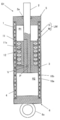
- FIG. 1 is a vertical sectional view of an electromagnetic shock absorber according to an embodiment.
- FIG. 2 is a diagram showing the pressure loss characteristic of the damping valve.
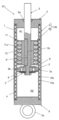
- FIG. 3 is a vertical cross-sectional view of the electromagnetic shock absorber in the first modified example of the embodiment.
- FIG. 4 is a diagram showing a characteristic of a force generated with respect to a piston speed of the electromagnetic shock absorber according to the embodiment.
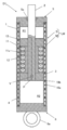
- FIG. 5 is a vertical cross-sectional view of the electromagnetic shock absorber in the second modified example of the embodiment.
- an electromagnetic shock absorber D1 includes a non-magnetic cylinder 1, a piston rod 2 movably inserted into the inner circumference of the cylinder 1, and a slidable inside the cylinder 1.
- a piston 3 which is inserted into the piston rod 2 and partitions the inside of the cylinder 1 into an expansion side chamber R1 and a compression side chamber R2, and a cylindrical mover M mounted on the piston rod 2 and the outer periphery of the cylinder 1.
- a linear motor LM provided with a cylindrical stator S facing the mover M, the working gas filled in the expansion side chamber R1 and the compression side chamber R2, and the expansion side chamber R1 and the compression side chamber R2 communicate with each other.
- the damping passage P and the damping valve V that gives resistance to the flow of the working gas passing through the damping passage P are configured.
- the cylinder 1 has a tubular shape and is formed of a non-magnetic material.
- a cylindrical back yoke 4 formed of a soft magnetic material that forms an annular gap between the cylinder 1 and the cylinder 1 is provided on the outer circumference of the cylinder 1.
- An annular rod guide 5 fitted to the upper end of the cylinder 1 in FIG. 1 is attached to the upper end of the back yoke 4 in FIG. 1, and the lower end of the back yoke 4 in FIG.
- a cap 6 that fits in is attached. It should be noted that the cap 6 is provided with a bracket 6a that can be mounted on a vehicle.
- the piston rod 2 is inserted through the inner circumference of the rod guide 5 and is movably inserted into the cylinder 1, and the piston 3 is provided on the outer circumference of the tip.
- a bracket that can be mounted on a vehicle is provided at the upper end in FIG. 1, which is the base end of the piston rod 2.
- a seal member 5a is provided on the inner circumference of the rod guide 5 to hermetically seal the inside of the cylinder 1.
- the piston 3 is slidably inserted into the cylinder 1 and divides the inside of the cylinder 1 into an expansion side chamber R1 and a compression side chamber R2.
- the expansion side chamber R1 and the compression side chamber R2 are filled with working gas.
- An inert gas such as nitrogen may be used as the working gas, but a gas other than nitrogen may be used. Since the pressure of the working gas has the property of being inversely proportional to the volume, even if the expansion side chamber R1 or the compression side chamber R2 is contracted by the displacement of the piston 3, sufficient damping force cannot be obtained unless the internal atmospheric pressure rises.
- the working gas is filled in the expansion side chamber R1 and the compression side chamber R2 at a high pressure so that a desired damping force can be obtained when the electromagnetic shock absorber D1 expands and contracts.
- the filling pressure of the working gas into the expansion side chamber R1 and the compression side chamber R2 is arbitrarily set according to the desired damping force.
- a cylindrical armature as a mover M is attached to the outer circumference of the piston rod 2.
- a damping passage P is provided which opens from a side portion above the mover M of the piston rod 2 in FIG.
- the damping passage P connects the expansion side chamber R1 and the compression side chamber R2.
- an orifice as a damping valve V is provided in the middle of the damping passage P.
- the damping valve V has a flow rate of the working gas passing through Q, a pressure loss generated with respect to the flow rate of the damping valve V passing through PL, and an arbitrary value larger than 1 is set to ⁇ , and an arbitrary value is set.
- the damping valve V may be a choke or a leaf valve other than the orifice, or may be a damping force adjusting valve capable of adjusting the damping force.
- the damping valve V includes, for example, a valve seat provided in the middle of a damping passage P provided in the piston rod 2, a valve body capable of being separated from and seated on the valve seat, and a valve.
- Variable flow passage area or valve opening pressure provided with a drive source that drives the body toward or away from the valve seat or an urging force generation source that can adjust the urging force that presses the valve body against the valve seat. It may be a valve that operates.
- the damping valve V is a damping force adjusting valve
- the damping valve V is provided inside the piston rod 2 and on the inner peripheral side of the mover M.
- the damping valve V is a damping force adjusting valve
- the outer diameter of the mover M is larger than that of the piston rod 2, and when the piston rod 2 is provided with a large-diameter portion other than the mounting portion of the mover M, the axis from the large-diameter portion to the mover M is increased.
- the length in the direction reduces the stroke length of the piston rod 2. Therefore, when the damping valve V is used as the damping force adjusting valve, when it is arranged inside the piston rod 2 and on the inner peripheral side of the mover M, there is an advantage that the stroke length of the electromagnetic shock absorber D1 can be easily secured. ..
- the driving source or the biasing force generating source is set to the piston rod 2 so as not to be affected by the magnetic field generated by energizing the mover M or the magnetic field generated by a field described later.
- 1 is provided at the upper end in FIG. 1 and adopts a structure in which the piston rod 2 is formed into a cylindrical shape and the power of the drive source or the urging force generation source is transmitted to the valve body through the control rod inserted into the piston rod 2. May be.
- damping passage P may be formed. Specifically, a gap is provided between the mover M and the piston 3, a compression side hole 3a and an extension side hole 3b that penetrate the piston 3 in the axial direction are provided, and the piston rod 2 is provided with the piston 3 and the mover M. A hole 2a is provided which opens from the space and communicates with the expansion side chamber R1. Then, the holes 2a, the compression side holes 3a, and the expansion side holes 3b may be used as the damping passages P. In this case, the pressure side leaf valve 8 that is stacked on the upper side in FIG.
- the piston 3 is attached to the piston rod 2 below the mover M in FIG. 3, but may be attached above the mover M in FIG.
- the mover M includes a core 11 mounted on the outer circumference of the piston rod 2 and a winding wire 12 mounted in a slot 11a formed of annular grooves arranged on the outer circumference of the core 11 at a predetermined pitch in the axial direction. And an armature in the present embodiment.
- the winding 12 mounted in the slot 11a is a U-phase, V-phase, and W-phase three-phase winding.
- An annular gap is provided between the outer periphery of the core 11 and the inner periphery of the cylinder 1 to prevent the core 11 and the cylinder 1 from directly interfering with each other.
- a plurality of annular permanent magnets 10a, 10b are laminated and mounted on the outer periphery of the cylinder 1, and these permanent magnets 10a, 10b are housed in an annular gap between the cylinder 1 and the back yoke 4.
- the permanent magnets 10a and 10b and the back yoke 4 constitute a field that alternately applies magnetic fields of S pole and N pole on the inner peripheral side of the cylinder 1.
- the stator S is formed. Since the cylinder 1 is made of a non-magnetic material, the magnetic field generated by the field can pass through the cylinder 1 and act inside the cylinder 1.
- the permanent magnet 10a of the main magnetic pole and the permanent magnet 10b of the auxiliary magnetic pole are laminated in the Halbach array so that the S poles and the N poles alternate in the axial direction on the inner peripheral side of the cylinder 1. ing.
- the triangular marks on the permanent magnet 10a of the main magnetic pole and the permanent magnet 10b of the auxiliary magnetic pole indicate the magnetizing direction, and the magnetizing direction of the permanent magnet 10a of the main magnetic pole is the radial direction. Therefore, the permanent magnet 10b of the auxiliary pole is magnetized in the axial direction.
- the axial length of the permanent magnet 10a of the main magnetic pole is longer than the axial length of the permanent magnet 10b of the auxiliary magnetic pole, and the magnetic field between the core 11 of the mover M and the permanent magnet 10a of the main magnetic pole is increased. Since the resistance can be reduced and the magnetic field acting on the core 11 can be increased, the thrust of the linear motor LM can be improved.
- the permanent magnets 10a and 10b need not be arranged in the Halbach arrangement, because the magnetic field may act on the inner peripheral side of the cylinder 1 so that the S poles and the N poles alternately appear in the axial direction. In that case, the permanent magnets 10a and 10b may have the same axial length and have different magnetic poles on their inner circumferences, and may be alternately laminated.
- the back yoke 4 can secure a magnetic path having a low magnetic resistance even if the axial length of the permanent magnet 10b of the auxiliary pole is shortened, a linear motor for increasing the axial length of the permanent magnet 10a of the main pole is provided.
- the thrust of the LM can be effectively improved. More specifically, when the back yoke 4 is provided on the outer circumference of the permanent magnets 10a and 10b, a magnetic path having a low magnetic resistance can be secured, so that the magnetic resistance increases due to the reduction of the axial length of the permanent magnet 10b of the auxiliary magnetic pole. Suppressed.
- the linear motor LM is driven. Thrust can be greatly improved.
- the thickness of the back yoke 4 may be set to a thickness suitable for suppressing an increase in external magnetic resistance of the permanent magnet 10a of the main pole. Since the back yoke 4 can secure a magnetic path having a low magnetic resistance even when the permanent magnets 10a and 10b are not arranged in the Halbach array, the thrust of the linear motor LM can be improved.
- the back yoke 4 also functions as an outer shell of the electromagnetic shock absorber D1, and also plays a role of protecting the permanent magnets 10a and 10b and a strength member that receives axial force and lateral force.
- the back yoke 4 can be omitted.
- the permanent magnets 10a and 10b do not function as a back yoke but are permanent magnets. It is preferable to provide a tube that protects 10a and 10b and functions as a strength member.
- the cylinder 1, the piston rod 2, the piston 3, the damping passage P, and the damping valve V constitute a gas damper, and the mover M of the linear motor LM is It is housed in the gas damper, the stator S is mounted on the outer periphery of the cylinder 1, and the linear motor LM and the gas damper are inseparably integrated.
- the electromagnetic shock absorber D1 is configured as described above, and its operation will be described below.
- the piston 3 moves upward in FIG. 1 with respect to the cylinder 1 to reduce the extension side chamber R1 and expand the compression side chamber R2.
- the working gas moves from the contracted expansion chamber R1 to the expanded compression chamber R2 via the damping passage P and the damping valve V. Since the working gas passes through the damping valve V, a pressure loss occurs in accordance with the flow rate of the working gas, and the pressure in the expansion side chamber R1 rises, causing a difference in pressure between the expansion side chamber R1 and the compression side chamber R2.
- the shock absorber D1 functions as a damper and generates a damping force that hinders the extension operation.
- the electromagnetic shock absorber D1 includes the linear motor LM, the thrust generated by the linear motor LM can be used as a damping force for suppressing the extension operation.
- the thrust of the linear motor LM can positively extend the electromagnetic shock absorber D1 to cause the electromagnetic shock absorber D1 to function as an actuator.
- the piston 3 moves downward in FIG. 1 with respect to the cylinder 1, and the compression side chamber R2 is contracted and the expansion side chamber R1 is expanded. Then, the working gas moves from the pressure side chamber R2 to be contracted to the expanding side chamber R1 via the damping passage P and the damping valve V. Since the working gas passes through the damping valve V, a pressure loss occurs in accordance with the flow rate of the working gas, and the pressure in the compression side chamber R2 rises, causing a difference in pressure between the compression side chamber R2 and the expansion side chamber R1.
- the shock absorber D1 functions as a damper and generates a damping force that hinders the contraction operation.
- the electromagnetic shock absorber D1 includes the linear motor LM, the thrust generated by the linear motor LM can be used as a damping force for suppressing the contraction operation.
- the thrust of the linear motor LM can positively contract the electromagnetic shock absorber D1 to cause the electromagnetic shock absorber D1 to function as an actuator.
- the generation limit of the thrust that can be generated while generating power when the linear motor LM is driven by an external force in a short-circuited state is as shown by the broken line in FIG. 4, and the linear motor LM of this case has The thrust depends on the increase of the piston speed until the moving speed of the mover M with respect to the stator S, that is, the piston speed that is the axial relative speed of the piston 3 with respect to the cylinder 1 of the electromagnetic shock absorber D1 reaches a high speed. It increases, but when it exceeds the high speed, it decreases as the piston speed increases. Note that FIG.
- the first quadrant in the figure is an electromagnetic field.
- the characteristics in the case where the shock absorber D1 exhibits an extension operation and exerts a damping force that hinders the extension is shown, and the second quadrant in the figure shows a state in which the electromagnetic damper D1 exhibits a contraction operation and exerts a thrust force that promotes contraction.
- the third quadrant shows characteristics in a state where the electromagnetic shock absorber D1 exhibits contraction operation and exhibits a damping force that prevents contraction.
- the electromagnetic shock absorber D1 exhibits expansion operation and promotes expansion. It shows the characteristics in the state of exerting thrust.
- the characteristic of the pressure loss of the damping valve V of the present embodiment is set so as to show a characteristic that it is small when the flow rate is small and increases when the flow rate is large.
- the flow rate passing through the damping valve V increases in proportion to the piston speed, and the damping force generated by the electromagnetic shock absorber D1 is proportional to the pressure loss generated by the damping valve V. Therefore, in the electromagnetic shock absorber D1 of the present embodiment, the pressure loss of the damping valve V is tuned to compensate for the decrease in the upper limit of the thrust that can be generated by the linear motor LM, and the electromagnetic shock absorber D1 is damped.
- the damping force characteristic when the damping force is generated only by the valve V is set as shown by the alternate long and short dash line in FIG.
- the electromagnetic shock absorber D1 can generate a necessary and sufficient damping force even if the piston speed becomes high. Further, when the electromagnetic shock absorber D1 is positively expanded/contracted by the thrust of the linear motor LM to be used as an actuator, the damping force exerted by the damping valve V acts as a resistance that prevents expansion/contraction of the electromagnetic shock absorber D1.
- the damping valve V Since the pressure loss PL generated with respect to the flow rate passing through the damping valve V is set to be proportional to Q ⁇ , at the piston speed when the electromagnetic shock absorber D1 is actively expanded and contracted, the damping valve V The damping force generated by can be made very small. Therefore, when the pressure loss PL generated with respect to the flow rate passing through the damping valve V is set to be proportional to Q ⁇ , when the electromagnetic shock absorber D1 is positively expanded and contracted to cause the electromagnetic shock absorber D1 to function as an actuator.
- the pressure loss characteristic of the damping valve V is not limited to the above-mentioned characteristic, and other characteristics may be used as long as they can compensate the thrust reduction of the linear motor LM when the piston speed becomes high. .. Further, when the damping valve V is a damping force adjusting valve capable of adjusting the damping force, the damping force generated by the electromagnetic shock absorber D1 can be adjusted, and when the electromagnetic shock absorber D1 functions as an actuator, the damping force is decreased. The resistance given to the flow of the working gas by the valve V can be minimized to suppress the thrust reduction due to the damping valve V.
- the piston 3 is slidably inserted into the cylinder 1, the mover M is attached to the piston rod 2, and the stator S is attached to the outer periphery of the cylinder 1. Since the mover M is kept concentric with the stator S, the thrust of the linear motor LM is not reduced. Further, in the present embodiment, the structure in which the field magnet is mounted on the outer circumference of the cylinder 1 as the stator S is adopted, but since the cylinder 1 is a non-magnetic body, the armature as the mover M is mounted.
- the piston 3 is provided at the tip of the piston rod 2 with respect to the mover M in the present embodiment, it may be provided at the base end side of the piston rod 2 with respect to the mover M. Also, as in the first second modification of the embodiment of the electromagnetic shock absorber D1 2 shown in FIG.
- the electromagnetic shock absorber D1 of the present invention includes the non-magnetic cylinder 1, the piston rod 2 movably inserted into the inner circumference of the cylinder 1, and the slidable insertion into the cylinder 1.
- a piston 3 provided on the piston rod 2 to divide the inside of the cylinder 1 into an expansion side chamber R1 and a compression side chamber R2, a cylindrical mover M mounted on the piston rod 2, and a mover provided on the outer circumference of the cylinder 1.
- a linear motor LM having a cylindrical stator S facing M, a working gas filled in the expansion side chamber R1 and the compression side chamber R2, and a damping passage P communicating between the expansion side chamber R1 and the compression side chamber R2.
- a damping valve V that provides resistance to the flow of the working gas passing through the damping passage P.
- the electromagnetic shock absorber D1 configured as described above includes the cylinder 1, the piston rod 2, the piston 3, the damping passage P, the gas damper including the damping valve V, the mover M, and the stator S.
- the constituted linear motor LM is inseparably integrated, the mover M of the linear motor LM is housed in the gas damper, and the stator S is mounted on the outer circumference of the cylinder 1. Therefore, according to the electromagnetic shock absorber D1 of the present invention, the size in the radial direction can be reduced as compared with the conventional electromagnetic shock absorber, so that the mountability on the vehicle is improved and the weight can be reduced.
- the sealing at the sliding portion is required only around the piston rod 2, so that it suffices to install only the seal member 5a. Therefore, it is possible to reduce friction during expansion and contraction of the electromagnetic shock absorber D1 and to reduce the cost. Can also be reduced. Therefore, according to the electromagnetic shock absorber D1 of the present invention, the mountability on the vehicle is improved, the weight and cost can be reduced, and the smooth expansion and contraction operation can be realized.
- stator S is used as a field and the mover M is used as an armature.
- an armature consisting of a core and a winding is attached to the outer periphery of the cylinder 1 and used as the stator S. It is also possible to attach a permanent magnet to the piston rod 2 to form a field and use this as the mover M.
- the electromagnetic shock absorber D1 of the present embodiment assuming that the flow rate passing through the damping passage P is Q and an arbitrary value greater than 1 is ⁇ , the pressure loss generated with respect to the flow rate passing through the damping valve V is , Q ⁇ are set so as to be proportional to Q ⁇ , it is possible to suppress the thrust reduction due to the damping valve V when the electromagnetic shock absorber D1 functions as an actuator, and the linear motor LM when the electromagnetic shock absorber functions as a damper. It is possible to compensate for the decrease in the thrust force with the damping force exerted by the damping valve V to exert a damping force suitable for the vehicle.
- the stator S has a field having a plurality of annular permanent magnets 10a and 10b mounted on the outer periphery of the cylinder 1 along the axial direction, and a field magnet. And a cylindrical back yoke 4 fitted to the outer periphery of the.
- the back yoke 4 can secure a magnetic path having a low magnetic resistance, and the back yoke 4 can be used as an outer shell of the electromagnetic shock absorber D1. Therefore, according to the electromagnetic shock absorber D1 configured as described above, not only can the thrust of the linear motor LM be improved, but also the permanent magnets 10a and 10b can be protected and the strength of the electromagnetic shock absorber D1 can be secured.
- the damping passage P communicates the expansion side chamber R1 and the compression side chamber R2 through the piston rod 2, and the damping valve V is inside the piston rod 2 and inside the mover M. It is provided on the circumference side.
- the damping valve V is arranged on the inner peripheral side of the mover M, so that the stroke length is long. It becomes easy to secure.
Landscapes
- Engineering & Computer Science (AREA)
- General Engineering & Computer Science (AREA)
- Mechanical Engineering (AREA)
- Physics & Mathematics (AREA)
- Electromagnetism (AREA)
- Combustion & Propulsion (AREA)
- Power Engineering (AREA)
- Chemical & Material Sciences (AREA)
- Acoustics & Sound (AREA)
- Aviation & Aerospace Engineering (AREA)
- Fluid-Damping Devices (AREA)
- Vehicle Body Suspensions (AREA)
- Vibration Prevention Devices (AREA)
- Linear Motors (AREA)
Abstract
本発明の電磁緩衝器(D)は、非磁性体のシリンダ(1)と、シリンダ(1)の内周に移動自在に挿入されるピストンロッド(2)と、シリンダ(1)内に摺動自在に挿入されるとともにピストンロッド(2)に設けられてシリンダ(1)内を伸側室(R1)と圧側室(R2)とに区画するピストン(3)と、ピストンロッド(2)に装着される筒状の可動子(M)とシリンダ(1)の外周に設けられて可動子(M)に対向する筒状の固定子(S)とを有するリニアモータ(LM)と、伸側室(R1)と圧側室(R2)とに充填される作動気体と、伸側室(R1)と圧側室(R2)とを連通する減衰通路(P)と、減衰通路(P)を通過する作動気体の流れに抵抗を与える減衰バルブ(V)とを備えている。
Description
本発明は、電磁緩衝器に関する。
電磁緩衝器は、たとえば、円筒状のリニアモータを備えており、リニアモータが発生する推力を自動車の車体の振動を抑制する減衰力として、或いは、車体の姿勢を制御する制御力として利用する。
しかしながら、このような電磁緩衝器では、リニアモータの推力だけでは大きな質量の車体の振動を抑制するのが難しいので、油圧利用のダンパを設けて不足する推力を補っている。
具体的には、電磁緩衝器は、ダンパの外周にダンパに並列するようにリニアモータを設けている(たとえば、特許文献1参照)。この電磁緩衝器におけるリニアモータは、ダンパの最外殻を成すインナーケーシングの外周に積層して装着される環状の永久磁石と、ダンパのピストンロッドの先端に取り付けたアウターケーシングの内周に設けたコイルとで構成されている。
このように構成された電磁緩衝器では、リニアモータに並列されたダンパを備えており、リニアモータが発生する推力とダンパが発生する減衰力とで車体の振動を抑制するようになっている。
従来の電磁緩衝器では、リニアモータとは別個独立したダンパを備えており、筒状のリニアモータがダンパの外周に設けられているため、径方向に大型化してしまうので車両への搭載性が悪化するとともに、重量が嵩んでしまう。
さらに、ダンパのシールの他、リニアモータ側でもリニアモータ内へのダストや水の浸入を阻止するためのシールが必要であるために、電磁緩衝器の伸縮時の摩擦が大きくなるだけでなく、コストも嵩んでしまう。
そこで、本発明は、車両への搭載性の向上と、重量およびコストを低減できるとともに、円滑な伸縮作動を実現できる電磁緩衝器の提供を目的としている。
上記の目的を達成するため、本発明の電磁緩衝器は、非磁性体のシリンダと、シリンダの内周に移動自在に挿入されるピストンロッドと、シリンダ内に摺動自在に挿入されるとともにピストンロッドに設けられてシリンダ内を伸側室と圧側室とに区画するピストンと、ピストンロッドに装着される筒状の可動子とシリンダの外周に設けられて可動子に対向する筒状の固定子とを有するリニアモータと、伸側室と圧側室とに充填される作動気体と、伸側室と圧側室とを連通する減衰通路と、通路を通過する作動気体の流れに抵抗を与える減衰バルブとを備えている。このように構成された電磁緩衝器は、シリンダとピストンロッドとピストンと減衰通路と減衰バルブとで構成されるガスダンパと、可動子と固定子とで構成されるリニアモータとが一体不可分に構成されており、リニアモータの可動子がガスダンパに収容されるとともに、固定子がシリンダの外周に装着される。
また、電磁緩衝器は、通路を通過する流量をQとし、1より大きな任意の値をαとすると、減衰バルブが通過する流量に対して発生する圧力損失は、Qαに比例するように設定されてもよい。このように構成された電磁緩衝器は、アクチュエータとして機能する場合には減衰バルブによる推力低下を抑制でき、ダンパとして機能する場合にはリニアモータの推力低下を減衰バルブが発揮する減衰力で補って車両に適する減衰力を発揮できる。
さらに、電磁緩衝器は、固定子がシリンダの外周に軸方向に沿って積層されて装着される複数の環状の永久磁石を有する界磁と、界磁の外周に嵌合される筒状のバックヨークとを有してもよい。このように構成された電磁緩衝器によれば、リニアモータの推力を向上できるだけでなく、永久磁石の保護が可能となるとともに、電磁緩衝器の強度を確保できる。
また、電磁緩衝器は、通路がピストンロッド内を通して伸側室と圧側室とを連通し、減衰バルブがピストンロッド内であって可動子の内周側に設けられていてもよい。このように構成された電磁緩衝器では、径方向にスペースが必要な減衰バルブを採用する場合であっても、可動子の内周側に減衰バルブが配置されるので、ストローク長を確保しやすくなる。
さらに、ピストンが可動子と隙間を空けてピストンロッドに設けられるとともにピストンを軸方向に貫通する伸側孔と圧側孔とを有し、減衰バルブがピストンの圧側室側に積層されて伸側孔を開閉する伸側リーフバルブとピストンの伸側室側に積層されて圧側孔を開閉する圧側リーフバルブとを有し、減衰通路がピストンロッドに設けられて伸側室或いは圧側室と隙間とを連通する孔、伸側孔および圧側孔とで形成されてもよい。このように構成された電磁緩衝器によれば、電磁緩衝器の伸長時と収縮時とで別個独立に減衰力をチューニングできる。
また、電磁緩衝器は、シリンダの内周に摺接するとともにピストンロッドに設けられるスライダを備え、可動子をピストンとスライダとの間に配置してもよい。このように構成された電磁緩衝器によれば、電磁緩衝器に横力が作用しても可動子の固定子に対する偏心を阻止でき、安定した減衰力を発揮できる。
本発明の電磁緩衝器によれば、車両への搭載性の向上と、重量およびコストを低減できるとともに、円滑な伸縮作動を実現できる。
以下、図に示した実施の形態に基づき、本発明を説明する。一実施の形態における電磁緩衝器D1は、図1に示すように、非磁性体のシリンダ1と、シリンダ1の内周に移動自在に挿入されるピストンロッド2と、シリンダ1内に摺動自在に挿入されるとともにピストンロッド2に設けられてシリンダ1内を伸側室R1と圧側室R2とに区画するピストン3と、ピストンロッド2に装着される筒状の可動子Mとシリンダ1の外周に設けられて可動子Mに対向する筒状の固定子Sとを有するリニアモータLMと、伸側室R1と圧側室R2とに充填される作動気体と、伸側室R1と圧側室R2とを連通する減衰通路Pと、減衰通路Pを通過する作動気体の流れに抵抗を与える減衰バルブVとを備えて構成されている。
以下、電磁緩衝器D1の各部について詳細に説明する。シリンダ1は、筒状であって非磁性体で形成されており、シリンダ1の外周にはシリンダ1との間に環状隙間を形成する軟磁性体で形成された筒状のバックヨーク4が設けられている。バックヨーク4の図1中上端には、シリンダ1の図1中上端に嵌合する環状のロッドガイド5が装着されており、バックヨーク4の図1中下端にはシリンダ1の図1中下端に嵌合するキャップ6が装着されている。なお、キャップ6には、車両への装着を可能とするブラケット6aが設けられている。
ピストンロッド2は、ロッドガイド5の内周に挿通されてシリンダ1内に移動自在に挿入されており、先端の外周にピストン3が設けられている。なお、図示はしないが、ピストンロッド2の基端である図1中上端には、車両への装着を可能とするブラケットが設けられる。また、ロッドガイド5の内周には、シール部材5aが設けられており、シリンダ1内が気密に密封されている。
ピストン3は、シリンダ1内に摺動自在に挿入されており、シリンダ1内を伸側室R1と圧側室R2とに区画している。伸側室R1と圧側室R2には、作動気体が充填されている。作動気体は、窒素などの不活性ガスを用いるとよいが、窒素以外の気体を利用してもよい。なお、作動気体の圧力は、体積に反比例する性質があるため、ピストン3の変位によって伸側室R1或いは圧側室R2が縮小されても内部の気圧が上昇しないと減衰力が十分に得られない。そのため、作動気体は、電磁緩衝器D1の伸縮時に所望する減衰力が得られるように伸側室R1と圧側室R2へ高い圧力で封入される。作動気体の伸側室R1と圧側室R2への封入圧力は、所望する減衰力に応じて任意に設定される。
また、ピストンロッド2の外周には、可動子Mとしての筒状の電機子が装着されている。さらに、ピストンロッド2の可動子Mよりも図1中上方の側部から開口して先端に通じる減衰通路Pが設けられている。減衰通路Pは、伸側室R1と圧側室R2とを連通している。また、減衰通路Pの途中には、減衰バルブVとしてオリフィスが設けられている。本実施の形態では、減衰バルブVは、通過する作動気体の流量をQとし、減衰バルブVが通過する流量に対して発生する圧力損失をPLとし、1より大きな任意の値をαとし、任意の係数をβとすると、減衰バルブVの圧力流量特性は、図2に示すように、PL=β×Qαとなるように設定されている。つまり、減衰バルブVが通過する流量に対して発生する圧力損失PLは、Qαに比例するように設定されている。
なお、減衰バルブVは、オリフィスの他にもチョークやリーフバルブとされてもよいし、減衰力調整可能な減衰力調整バルブとされてもよい。減衰バルブVを減衰力調整バルブとする場合、減衰バルブVは、たとえば、ピストンロッド2内に設けた減衰通路Pの途中に設けた弁座と、弁座に離着座可能な弁体と、弁体を弁座に対して遠近させる方向に駆動する駆動源或いは弁体を弁座に対して押圧する付勢力を調節可能な付勢力発生源とを備えて流路面積或いは開弁圧を可変にするバルブ等とされればよい。
減衰バルブVを減衰力調整バルブとする場合、ピストンロッド2内であって可動子Mの内周側に設けられるとよい。減衰バルブVは、減衰力調整バルブであるとピストンロッド2内に径方向に大きな収容スペースを確保することが必要な場合が多く、可動子Mと軸方向にずれた位置に設けられると、ピストンロッド2に可動子Mとはずれた位置に大径部が必要な場合がある。可動子Mの外径は、ピストンロッド2よりも大径であって、ピストンロッド2に可動子Mの装着部位以外に大径部が設けられると、この大径部から可動子Mまでの軸方向長さはピストンロッド2のストローク長を減殺してしまう。よって、減衰バルブVを減衰力調整バルブとする場合、ピストンロッド2内であって可動子Mの内周側に配置されると、電磁緩衝器D1のストローク長を確保しやすくなるという利点がある。
なお、減衰バルブVを減衰力調整バルブとする場合、可動子Mへの通電によって発生する磁界や後述する界磁による磁界の影響を受けないように、駆動源或いは付勢力発生源をピストンロッド2の図1中上端に設けて、ピストンロッド2を筒状として駆動源或いは付勢力発生源の動力をピストンロッド2内に挿通されるコントロールロッドを介して弁体に伝達するような構成を採用してもよい。
また、本実施の形態では、減衰通路Pの全ては、ピストンロッド2に設けられているが、図3に示した第一の実施の形態の第一変形例の電磁緩衝器D11のように、減衰通路Pを形成してもよい。具体的には、可動子Mとピストン3との間に隙間を設け、ピストン3に軸方向に貫通する圧側孔3aと伸側孔3bを設けるとともに、ピストンロッド2にピストン3と可動子Mとの間から開口して伸側室R1へ通じる孔2aを設ける。そして、これら孔2a、圧側孔3aおよび伸側孔3bを減衰通路Pとして利用すればよい。この場合、ピストン3の伸側室側である図3中上側に積層されて圧側孔3aを開閉する圧側リーフバルブ8と、ピストン3の圧側室側である図3中下側に積層されて伸側孔3bを開閉する伸側リーフバルブ9とを設けて、これらリーフバルブ8,9を減衰バルブVとしてもよい。このようにすると、電磁緩衝器D11の伸長時には、圧側リーフバルブ8が圧側孔3aを閉じて伸側リーフバルブ9が伸側孔3bを開いて作動気体の流れに抵抗を与え、電磁緩衝器D11の収縮時には、伸側リーフバルブ9が伸側孔3bを閉じて圧側リーフバルブ8が圧側孔3aを開いて作動気体の流れに抵抗を与える。よって、このようにすれば、電磁緩衝器D11の伸長時と収縮時とで別個独立に減衰力をチューニングできる。なお、ピストン3は、ピストンロッド2に対して可動子Mの図3中下方に取り付けられているが、可動子Mの図3中上方に取り付けられてもよい。
戻って、可動子Mは、ピストンロッド2の外周に装着されるコア11と、コア11の外周に軸方向に所定ピッチで並べて設けられた環状溝でなるスロット11a内に装着される巻線12とを備えて構成されており、本実施の形態では、電機子とされている。なお、スロット11aに装着される巻線12は、U相、V相およびW相の三相巻線とされている。コア11の外周とシリンダ1の内周との間には、環状の空隙が設けられており、コア11とシリンダ1とが直接干渉しないように配慮されている。
シリンダ1の外周には、複数の環状の永久磁石10a,10bが積層されて装着されており、これら永久磁石10a,10bは、シリンダ1とバックヨーク4との間の環状隙間内に収容されている。そして、本実施の形態では、永久磁石10a,10bとバックヨーク4とでシリンダ1の内周側に交互にS極とN極の磁界を作用させる界磁を構成しており、この界磁で固定子Sが形成されている。シリンダ1は非磁性体で構成されているので、界磁が発生する磁界は、シリンダ1を透過してシリンダ1内へ作用できる。
また、本実施の形態では、主磁極の永久磁石10aと副磁極の永久磁石10bは、ハルバッハ配列にてシリンダ1の内周側に軸方向でS極とN極が交互に現れるように積層されている。図1中で主磁極の永久磁石10aと副磁極の永久磁石10bに記載されている三角の印は、着磁方向を示しており、主磁極の永久磁石10aの着磁方向は径方向となっており、副磁極の永久磁石10bの着磁方向は軸方向となっている。なお、主磁極の永久磁石10aの軸方向長さは、副磁極の永久磁石10bの軸方向長さよりも長くなっており、可動子Mにおけるコア11と主磁極の永久磁石10aとの間の磁気抵抗を小さくできコア11へ作用させる磁界を大きくできるのでリニアモータLMの推力を向上できる。なお、永久磁石10a,10bは、シリンダ1の内周側に軸方向でS極とN極が交互に現れるように磁界を作用させればよいので、ハルバッハ配列で配列されていなくともよい。その場合には、永久磁石10a,10bは、ともに軸方向長さが等しく、互いに内周に異なる磁極を備えていればよく、交互に積層されればよい。
バックヨーク4は、副磁極の永久磁石10bの軸方向長さを短くしても磁気抵抗の低い磁路を確保できるため、主磁極の永久磁石10aの軸方向長さを長くする際のリニアモータLMの推力を効果的に向上できる。より詳しくは、永久磁石10a,10bの外周にバックヨーク4を設けると、磁気抵抗の低い磁路を確保できるので副磁極の永久磁石10bの軸方向長さの短縮に起因する磁気抵抗の増大が抑制される。よって、主磁極の永久磁石10aの軸方向長さを副磁極の永久磁石10bの軸方向長さよりも長くするとともに永久磁石10a,10bの外周に筒状のバックヨーク4を設けるとリニアモータLMの推力を大きく向上させ得る。バックヨーク4の肉厚は、主磁極の永久磁石10aの外部磁気抵抗の増大を抑制に適する肉厚に設定されればよい。バックヨーク4は、永久磁石10a,10bがハルバッハ配列とされていない場合でも磁気抵抗の低い磁路を確保できるのでリニアモータLMの推力を向上させ得る。
本実施の形態では、バックヨーク4は、電磁緩衝器D1のアウターシェルとしても機能しており、永久磁石10a,10bの保護と軸力や横力を受ける強度部材としての役割も果たしている。バックヨーク4を設けると磁気抵抗の増大を抑制できるが、バックヨーク4の省略も可能であり、バックヨーク4を省略する場合、永久磁石10a,10bの外周にバックヨークとしては機能しないが永久磁石10a,10bの保護と強度部材としての機能を発揮する筒を設けると良い。
このように構成された電磁緩衝器D1では、シリンダ1と、ピストンロッド2と、ピストン3と、減衰通路Pと、減衰バルブVとでガスダンパを構成しており、リニアモータLMの可動子Mがガスダンパ内に収容されるとともに、固定子Sがシリンダ1の外周に装着されていて、リニアモータLMとガスダンパとが一体不可分に構成されている。
電磁緩衝器D1は、以上のように構成され、以下、その作動について説明する。電磁緩衝器D1が外力によって伸長作動する場合、ピストン3がシリンダ1に対して図1中上方へ移動して、伸側室R1を縮小して圧側室R2を拡大する。すると、作動気体は、縮小される伸側室R1から減衰通路Pおよび減衰バルブVを介して拡大する圧側室R2へ移動する。減衰バルブVを作動気体が通過するために、通過する流量に応じて圧力損失が発生して、伸側室R1の圧力が上昇して伸側室R1と圧側室R2の圧力に差が生じるので、電磁緩衝器D1は、ダンパとして機能して伸長作動を妨げる減衰力を発生する。また、電磁緩衝器D1は、リニアモータLMを備えているので、リニアモータLMが発生する推力を伸長作動を抑制する減衰力として利用できる。これに対して、リニアモータLMの推力で電磁緩衝器D1を積極的に伸長させて電磁緩衝器D1をアクチュエータとして機能させ得る。
電磁緩衝器D1が外力によって収縮作動する場合、ピストン3がシリンダ1に対して図1中下方へ移動して、圧側室R2を縮小して伸側室R1を拡大する。すると、作動気体は、縮小される圧側室R2から減衰通路Pおよび減衰バルブVを介して拡大する伸側室R1へ移動する。減衰バルブVを作動気体が通過するために、通過する流量に応じて圧力損失が発生して、圧側室R2の圧力が上昇して圧側室R2と伸側室R1の圧力に差が生じるので、電磁緩衝器D1は、ダンパとして機能して収縮作動を妨げる減衰力を発生する。また、電磁緩衝器D1は、リニアモータLMを備えているので、リニアモータLMが発生する推力を収縮作動を抑制する減衰力として利用できる。これに対して、リニアモータLMの推力で電磁緩衝器D1を積極的に収縮させて電磁緩衝器D1をアクチュエータとして機能させ得る。
リニアモータLMが短絡された状態で外力によって駆動させられた場合に発電しつつ発生可能な推力の発生限界は、図4中の波線に示したようになっており、この場合のリニアモータLMの推力は、固定子Sに対する可動子Mの移動速度、つまり、電磁緩衝器D1のシリンダ1に対するピストン3の軸方向の相対速度であるピストン速度が高速に到達するまではピストン速度の上昇に応じて大きくなるが高速を超えるとピストン速度の上昇に応じて小さくなっていく。なお、図4は、電磁緩衝器D1が全体として発生可能な力(リニアモータLMの推力とガスダンパの減衰力の総和の力)の特性を図示したものであり、図中の第一象限は電磁緩衝器D1が伸長作動を呈して伸長を妨げる減衰力を発揮する場合の特性を示し、図中の第二象限は電磁緩衝器D1が収縮作動を呈して収縮を助長する推力を発揮する状態における特性を示し、第三象限は電磁緩衝器D1が収縮作動を呈して収縮を妨げる減衰力を発揮する状態における特性を示し、第四象限は、電磁緩衝器D1が伸長作動を呈して伸長を助長する推力を発揮する状態における特性を示している。
そして、本実施の形態の減衰バルブVの圧力損失の特性は、流量が少ない場合には小さく、流量が多くなると大きくなる特性を示すように設定されている。減衰バルブVを通過する流量は、ピストン速度に比例して多くなり、電磁緩衝器D1が発生する減衰力は、減衰バルブVが発生する圧力損失に比例する。よって、本実施の形態における電磁緩衝器D1では、減衰バルブVの圧力損失をチューニングして、リニアモータLMが発生可能な推力の上限が低下する分を補うようにして、電磁緩衝器D1が減衰バルブVのみで減衰力を発生する場合の減衰力特性を図4中の一点鎖線で示すように設定している。このようにすると、リニアモータLMが発生可能な最大推力と減衰バルブVによって発生される減衰力の総和は、図4中実線で示すようになる。よって、電磁緩衝器D1は、ピストン速度が高速となっても必要十分な減衰力を発生できる。また、電磁緩衝器D1をリニアモータLMの推力で積極的に伸縮させてアクチュエータとして利用する場合には、減衰バルブVが発揮する減衰力が電磁緩衝器D1の伸縮を妨げる抵抗として働いてしまう。しかしながら、減衰バルブVが通過する流量に対して発生する圧力損失PLをQαに比例するように設定しているので、電磁緩衝器D1を積極的に伸縮させる場合のピストン速度では、減衰バルブVによって発生する減衰力を非常に小さくすることができる。よって、減衰バルブVが通過する流量に対して発生する圧力損失PLをQαに比例するように設定すると、積極的に電磁緩衝器D1を伸縮させて電磁緩衝器D1をアクチュエータとして機能させる場合には、減衰バルブVによる推力低下を抑制できるとともに、電磁緩衝器D1がダンパとして機能する場合にはリニアモータLMの推力低下を減衰バルブVが発揮する減衰力で補って車両に適する減衰力を発揮できる。
なお、減衰バルブVの圧力損失特性は、前述した特性に限定されるものではなく、他の特性であっても、ピストン速度が高速となった際にリニアモータLMの推力低下を補えればよい。また、減衰バルブVが減衰力調整可能な減衰力調整バルブである場合には、電磁緩衝器D1が発生する減衰力の調整が可能であり、電磁緩衝器D1がアクチュエータとして機能する場合には減衰バルブVが作動気体の流れに与える抵抗を最小にして減衰バルブVによる推力低下を抑制できる。
また、本実施の形態の電磁緩衝器D1は、ピストン3がシリンダ1に摺動自在に挿入されており、可動子Mがピストンロッド2に装着されるとともにシリンダ1の外周に固定子Sが装着されているので、可動子Mが固定子Sに対して同心に保たれるために、リニアモータLMの推力低下を招かない。また、本実施の形態では、界磁を固定子Sとしてシリンダ1の外周に装着する構造を採用しているが、シリンダ1が非磁性体であるため、可動子Mとしての電機子を装着したピストンロッド2を界磁が装着されたシリンダ1内に挿入する組立工程にあっても、可動子Mと固定子Sとの接触が回避されるので、組立工程時に永久磁石10a,10bを保護できる。なお、ピストン3は、本実施の形態では、可動子Mよりもピストンロッド2の先端に設けられているが、可動子Mよりもピストンロッド2の基端側に設けられてもよい。また、図5に示した第一の実施の形態の第二変形例の電磁緩衝器D12のように、ピストン3の他に、ピストンロッド2にシリンダ1の内周に摺接するスライダ13を設けて、可動子Mをピストン3とスライダ13との間に配置するようにすれば、電磁緩衝器D1に横力が作用しても可動子Mの固定子Sに対する偏心を阻止できるので、電磁緩衝器D1は、安定した減衰力を発揮できる。
このように、本発明の電磁緩衝器D1は、非磁性体のシリンダ1と、シリンダ1の内周に移動自在に挿入されるピストンロッド2と、シリンダ1内に摺動自在に挿入されるとともにピストンロッド2に設けられてシリンダ1内を伸側室R1と圧側室R2とに区画するピストン3と、ピストンロッド2に装着される筒状の可動子Mとシリンダ1の外周に設けられて可動子Mに対向する筒状の固定子Sとを有するリニアモータLMと、伸側室R1と圧側室R2とに充填される作動気体と、伸側室R1と圧側室R2とを連通する減衰通路Pと、減衰通路Pを通過する作動気体の流れに抵抗を与える減衰バルブVとを備えている。
このように構成された電磁緩衝器D1は、シリンダ1と、ピストンロッド2と、ピストン3と、減衰通路Pと、減衰バルブVとで構成されるガスダンパと、可動子Mと固定子Sとで構成されるリニアモータLMとが一体不可分に構成されており、リニアモータLMの可動子Mがガスダンパ内に収容されるとともに、固定子Sがシリンダ1の外周に装着されている。よって、本発明の電磁緩衝器D1によれば、従来の電磁緩衝器に比較して、径方向の寸法を小型化できるので車両への搭載性が向上し、重量も軽減できる。さらに、電磁緩衝器D1では、摺動部においてシールが必要なのはピストンロッド2の周囲だけとなるので、シール部材5aのみの設置で足りるから、電磁緩衝器D1の伸縮時の摩擦を低減できるとともにコストも軽減できる。したがって、本発明の電磁緩衝器D1によれば、車両への搭載性が向上し、重量およびコストを低減できるとともに、円滑な伸縮作動を実現できるのである。
なお、前述したところでは、固定子Sを界磁として、可動子Mを電機子としているが、シリンダ1の外周にコアと巻線とでなる電機子を装着してこれを固定子Sとし、ピストンロッド2に永久磁石を装着して界磁を形成してこれを可動子Mとすることもできる。
また、本実施の形態の電磁緩衝器D1では、減衰通路Pを通過する流量をQとし、1より大きな任意の値をαとすると、減衰バルブVが通過する流量に対して発生する圧力損失は、Qαに比例するように設定されているので、電磁緩衝器D1をアクチュエータとして機能させる場合には減衰バルブVによる推力低下を抑制でき、電磁緩衝器をダンパとして機能させる場合にはリニアモータLMの推力低下を減衰バルブVが発揮する減衰力で補って車両に適する減衰力を発揮できる。
さらに、本実施の形態の電磁緩衝器D1では、固定子Sがシリンダ1の外周に軸方向に沿って積層されて装着される複数の環状の永久磁石10a,10bを有する界磁と、界磁の外周に嵌合される筒状のバックヨーク4とを備えている。このように構成された電磁緩衝器D1では、バックヨーク4によって磁気抵抗の低い磁路を確保でき、バックヨーク4を電磁緩衝器D1のアウターシェルとして利用できる。よって、このように構成された電磁緩衝器D1によれば、リニアモータLMの推力を向上できるだけでなく、永久磁石10a,10bの保護が可能となるとともに、電磁緩衝器D1の強度を確保できる。
さらに、本実施の形態の電磁緩衝器D1では、減衰通路Pがピストンロッド2内を通して伸側室R1と圧側室R2とを連通し、減衰バルブVがピストンロッド2内であって可動子Mの内周側に設けられている。このように構成された電磁緩衝器D1では、径方向にスペースが必要な減衰バルブVを採用する場合であっても、可動子Mの内周側に減衰バルブVが配置されるので、ストローク長を確保しやすくなる。
以上、本発明の好ましい実施の形態を詳細に説明したが、特許請求の範囲から逸脱しない限り、改造、変形、および変更が可能である。
1・・・シリンダ、2・・・ピストンロッド、2a・・・孔、3・・・ピストン、4・・・バックヨーク、10a,10b・・・永久磁石、D1,D11,D12・・・電磁緩衝器、LM・・・リニアモータ、M・・・可動子、P・・・減衰通路、R1・・・伸側室、R2・・・圧側室、S・・・固定子、V・・・減衰バルブ
Claims (6)
- 電磁緩衝器であって、
非磁性体のシリンダと、
前記シリンダの内周に移動自在に挿入されるピストンロッドと、
前記シリンダ内に摺動自在に挿入されるとともに前記ピストンロッドに設けられて前記シリンダ内を伸側室と圧側室とに区画するピストンと、
前記ピストンロッドに装着される筒状の可動子と前記シリンダの外周に設けられて前記可動子に対向する筒状の固定子とを有するリニアモータと、
前記伸側室と前記圧側室とに充填される作動気体と、
前記伸側室と前記圧側室とを連通する減衰通路と、
前記減衰通路を通過する作動気体の流れに抵抗を与える減衰バルブとを備えた
電磁緩衝器。 - 請求項1に記載の電磁緩衝器であって、
前記減衰通路を通過する流量をQとし、1より大きな任意の値をαとすると、前記減衰バルブが通過する流量に対して発生する圧力損失は、Qαに比例するように設定されている
電磁緩衝器。 - 請求項1に記載の電磁緩衝器であって、
前記固定子は、
前記シリンダの外周に軸方向に沿って積層されて装着される複数の環状の永久磁石を有する界磁と、
前記界磁の外周に嵌合される筒状のバックヨークとを有する
電磁緩衝器。 - 請求項1に記載の電磁緩衝器であって、
前記減衰通路は、前記ピストンロッド内を通して前記伸側室と前記圧側室とを連通し、
前記減衰バルブは、前記ピストンロッド内であって前記可動子の内周側に設けられている
電磁緩衝器。 - 請求項1に記載の電磁緩衝器であって、
前記ピストンは、前記可動子と隙間を空けて前記ピストンロッドに設けられるとともに前記ピストンを軸方向に貫通する伸側孔と圧側孔とを有し、
前記減衰バルブは、前記ピストンの圧側室側に積層されて前記伸側孔を開閉する伸側リーフバルブと、前記ピストンの伸側室側に積層されて前記圧側孔を開閉する圧側リーフバルブとを有し、
前記減衰通路は、前記ピストンロッドに設けられて前記伸側室或いは前記圧側室と前記隙間とを連通する孔、前記伸側孔および前記圧側孔とで形成される
電磁緩衝器。 - 請求項1に記載の電磁緩衝器であって、
前記シリンダの内周に摺接するとともに前記ピストンロッドに設けられるスライダを備え、
前記可動子を前記ピストンと前記スライダとの間に配置した
電磁緩衝器。
Applications Claiming Priority (2)
| Application Number | Priority Date | Filing Date | Title |
|---|---|---|---|
| JP2019-017306 | 2019-02-01 | ||
| JP2019017306A JP7121672B2 (ja) | 2019-02-01 | 2019-02-01 | 電磁緩衝器 |
Publications (1)
| Publication Number | Publication Date |
|---|---|
| WO2020158754A1 true WO2020158754A1 (ja) | 2020-08-06 |
Family
ID=71842137
Family Applications (1)
| Application Number | Title | Priority Date | Filing Date |
|---|---|---|---|
| PCT/JP2020/003036 Ceased WO2020158754A1 (ja) | 2019-02-01 | 2020-01-28 | 電磁緩衝器 |
Country Status (2)
| Country | Link |
|---|---|
| JP (1) | JP7121672B2 (ja) |
| WO (1) | WO2020158754A1 (ja) |
Cited By (2)
| Publication number | Priority date | Publication date | Assignee | Title |
|---|---|---|---|---|
| CN113081571A (zh) * | 2021-04-23 | 2021-07-09 | 王涛 | 一种耦合式立柱电机 |
| CN113266660A (zh) * | 2021-06-10 | 2021-08-17 | 浙江戈尔德智能悬架股份有限公司 | 一种新型内置cdc减振器 |
Families Citing this family (1)
| Publication number | Priority date | Publication date | Assignee | Title |
|---|---|---|---|---|
| CN118100578B (zh) * | 2024-04-28 | 2024-07-26 | 中国人民解放军海军工程大学 | 一种基于振动主动控制电磁作动器的磁组件结构 |
Citations (5)
| Publication number | Priority date | Publication date | Assignee | Title |
|---|---|---|---|---|
| JPS6320206A (ja) * | 1986-07-14 | 1988-01-27 | ザ・フアイヤ−スト−ン・タイヤ・アンド・ラバ−・カンパニ− | 空気ばね懸架装置及び空気ばね |
| JPS63287629A (ja) * | 1987-05-21 | 1988-11-24 | Daihatsu Motor Co Ltd | パワ−ユニットの大挙動抑制装置 |
| JPH06235436A (ja) * | 1993-02-08 | 1994-08-23 | Kayaba Ind Co Ltd | 減衰バルブ |
| JP2002257189A (ja) * | 2001-02-28 | 2002-09-11 | Tokico Ltd | 電磁サスペンション装置 |
| JP2008286362A (ja) * | 2007-05-21 | 2008-11-27 | Aisin Seiki Co Ltd | サスペンション装置 |
-
2019
- 2019-02-01 JP JP2019017306A patent/JP7121672B2/ja active Active
-
2020
- 2020-01-28 WO PCT/JP2020/003036 patent/WO2020158754A1/ja not_active Ceased
Patent Citations (5)
| Publication number | Priority date | Publication date | Assignee | Title |
|---|---|---|---|---|
| JPS6320206A (ja) * | 1986-07-14 | 1988-01-27 | ザ・フアイヤ−スト−ン・タイヤ・アンド・ラバ−・カンパニ− | 空気ばね懸架装置及び空気ばね |
| JPS63287629A (ja) * | 1987-05-21 | 1988-11-24 | Daihatsu Motor Co Ltd | パワ−ユニットの大挙動抑制装置 |
| JPH06235436A (ja) * | 1993-02-08 | 1994-08-23 | Kayaba Ind Co Ltd | 減衰バルブ |
| JP2002257189A (ja) * | 2001-02-28 | 2002-09-11 | Tokico Ltd | 電磁サスペンション装置 |
| JP2008286362A (ja) * | 2007-05-21 | 2008-11-27 | Aisin Seiki Co Ltd | サスペンション装置 |
Cited By (2)
| Publication number | Priority date | Publication date | Assignee | Title |
|---|---|---|---|---|
| CN113081571A (zh) * | 2021-04-23 | 2021-07-09 | 王涛 | 一种耦合式立柱电机 |
| CN113266660A (zh) * | 2021-06-10 | 2021-08-17 | 浙江戈尔德智能悬架股份有限公司 | 一种新型内置cdc减振器 |
Also Published As
| Publication number | Publication date |
|---|---|
| JP2020125780A (ja) | 2020-08-20 |
| JP7121672B2 (ja) | 2022-08-18 |
Similar Documents
| Publication | Publication Date | Title |
|---|---|---|
| CN107923472B (zh) | 阻尼力可调式减振器 | |
| CN109416102B (zh) | 阻尼力调整式缓冲器 | |
| WO2020158753A1 (ja) | 電磁緩衝器 | |
| JP7079213B2 (ja) | 電磁緩衝器 | |
| CN104204602B (zh) | 振幅敏感的液压阻尼器 | |
| JP7085689B2 (ja) | 減衰力調整式緩衝器 | |
| WO2020158754A1 (ja) | 電磁緩衝器 | |
| CN103026094B (zh) | 缓冲器的阻尼阀 | |
| JP5603724B2 (ja) | リニアアクチュエータ | |
| WO2012039293A1 (ja) | リニアアクチュエータ | |
| JPWO2021117800A5 (ja) | ||
| JP2008224001A (ja) | 可変減衰力ダンパ | |
| JP2005291284A (ja) | ダンパ | |
| JP5818201B2 (ja) | 緩衝器 | |
| JP7324934B2 (ja) | 緩衝器 | |
| JP2018035811A (ja) | 緩衝器 | |
| KR20240097956A (ko) | 솔레노이드, 감쇠력 조정 기구 및 감쇠력 조정식 완충기 | |
| JP2017048817A (ja) | 減衰力調整式緩衝器 | |
| JP2022190948A (ja) | 減衰力調整式緩衝器 | |
| WO2023157503A1 (ja) | ソレノイド、減衰力調整機構および減衰力調整式緩衝器 | |
| JP6200219B2 (ja) | ソレノイドバルブおよび緩衝器 | |
| WO2020158755A1 (ja) | 電磁緩衝器 | |
| JP2024122374A (ja) | 減衰バルブおよび緩衝器 | |
| WO2013122252A1 (ja) | ショックアブソーバ | |
| JP2005226772A (ja) | ショックアブソーバ |
Legal Events
| Date | Code | Title | Description |
|---|---|---|---|
| 121 | Ep: the epo has been informed by wipo that ep was designated in this application |
Ref document number: 20748241 Country of ref document: EP Kind code of ref document: A1 |
|
| NENP | Non-entry into the national phase |
Ref country code: DE |
|
| 122 | Ep: pct application non-entry in european phase |
Ref document number: 20748241 Country of ref document: EP Kind code of ref document: A1 |