WO2020157533A1 - Procédé de commande de déplacement et dispositif de commande de déplacement pour véhicule - Google Patents
Procédé de commande de déplacement et dispositif de commande de déplacement pour véhicule Download PDFInfo
- Publication number
- WO2020157533A1 WO2020157533A1 PCT/IB2019/000120 IB2019000120W WO2020157533A1 WO 2020157533 A1 WO2020157533 A1 WO 2020157533A1 IB 2019000120 W IB2019000120 W IB 2019000120W WO 2020157533 A1 WO2020157533 A1 WO 2020157533A1
- Authority
- WO
- WIPO (PCT)
- Prior art keywords
- vehicle
- control
- host vehicle
- width
- stop
- Prior art date
Links
Images

Classifications
-
- B—PERFORMING OPERATIONS; TRANSPORTING
- B60—VEHICLES IN GENERAL
- B60W—CONJOINT CONTROL OF VEHICLE SUB-UNITS OF DIFFERENT TYPE OR DIFFERENT FUNCTION; CONTROL SYSTEMS SPECIALLY ADAPTED FOR HYBRID VEHICLES; ROAD VEHICLE DRIVE CONTROL SYSTEMS FOR PURPOSES NOT RELATED TO THE CONTROL OF A PARTICULAR SUB-UNIT
- B60W60/00—Drive control systems specially adapted for autonomous road vehicles
- B60W60/001—Planning or execution of driving tasks
- B60W60/0013—Planning or execution of driving tasks specially adapted for occupant comfort
-
- B—PERFORMING OPERATIONS; TRANSPORTING
- B60—VEHICLES IN GENERAL
- B60W—CONJOINT CONTROL OF VEHICLE SUB-UNITS OF DIFFERENT TYPE OR DIFFERENT FUNCTION; CONTROL SYSTEMS SPECIALLY ADAPTED FOR HYBRID VEHICLES; ROAD VEHICLE DRIVE CONTROL SYSTEMS FOR PURPOSES NOT RELATED TO THE CONTROL OF A PARTICULAR SUB-UNIT
- B60W30/00—Purposes of road vehicle drive control systems not related to the control of a particular sub-unit, e.g. of systems using conjoint control of vehicle sub-units, or advanced driver assistance systems for ensuring comfort, stability and safety or drive control systems for propelling or retarding the vehicle
- B60W30/14—Adaptive cruise control
- B60W30/143—Speed control
- B60W30/146—Speed limiting
-
- B—PERFORMING OPERATIONS; TRANSPORTING
- B60—VEHICLES IN GENERAL
- B60W—CONJOINT CONTROL OF VEHICLE SUB-UNITS OF DIFFERENT TYPE OR DIFFERENT FUNCTION; CONTROL SYSTEMS SPECIALLY ADAPTED FOR HYBRID VEHICLES; ROAD VEHICLE DRIVE CONTROL SYSTEMS FOR PURPOSES NOT RELATED TO THE CONTROL OF A PARTICULAR SUB-UNIT
- B60W40/00—Estimation or calculation of non-directly measurable driving parameters for road vehicle drive control systems not related to the control of a particular sub unit, e.g. by using mathematical models
- B60W40/08—Estimation or calculation of non-directly measurable driving parameters for road vehicle drive control systems not related to the control of a particular sub unit, e.g. by using mathematical models related to drivers or passengers
-
- B—PERFORMING OPERATIONS; TRANSPORTING
- B60—VEHICLES IN GENERAL
- B60W—CONJOINT CONTROL OF VEHICLE SUB-UNITS OF DIFFERENT TYPE OR DIFFERENT FUNCTION; CONTROL SYSTEMS SPECIALLY ADAPTED FOR HYBRID VEHICLES; ROAD VEHICLE DRIVE CONTROL SYSTEMS FOR PURPOSES NOT RELATED TO THE CONTROL OF A PARTICULAR SUB-UNIT
- B60W40/00—Estimation or calculation of non-directly measurable driving parameters for road vehicle drive control systems not related to the control of a particular sub unit, e.g. by using mathematical models
- B60W40/10—Estimation or calculation of non-directly measurable driving parameters for road vehicle drive control systems not related to the control of a particular sub unit, e.g. by using mathematical models related to vehicle motion
- B60W40/105—Speed
-
- B—PERFORMING OPERATIONS; TRANSPORTING
- B60—VEHICLES IN GENERAL
- B60W—CONJOINT CONTROL OF VEHICLE SUB-UNITS OF DIFFERENT TYPE OR DIFFERENT FUNCTION; CONTROL SYSTEMS SPECIALLY ADAPTED FOR HYBRID VEHICLES; ROAD VEHICLE DRIVE CONTROL SYSTEMS FOR PURPOSES NOT RELATED TO THE CONTROL OF A PARTICULAR SUB-UNIT
- B60W50/00—Details of control systems for road vehicle drive control not related to the control of a particular sub-unit, e.g. process diagnostic or vehicle driver interfaces
- B60W50/02—Ensuring safety in case of control system failures, e.g. by diagnosing, circumventing or fixing failures
- B60W50/0205—Diagnosing or detecting failures; Failure detection models
-
- B—PERFORMING OPERATIONS; TRANSPORTING
- B60—VEHICLES IN GENERAL
- B60W—CONJOINT CONTROL OF VEHICLE SUB-UNITS OF DIFFERENT TYPE OR DIFFERENT FUNCTION; CONTROL SYSTEMS SPECIALLY ADAPTED FOR HYBRID VEHICLES; ROAD VEHICLE DRIVE CONTROL SYSTEMS FOR PURPOSES NOT RELATED TO THE CONTROL OF A PARTICULAR SUB-UNIT
- B60W60/00—Drive control systems specially adapted for autonomous road vehicles
- B60W60/001—Planning or execution of driving tasks
- B60W60/0015—Planning or execution of driving tasks specially adapted for safety
- B60W60/0018—Planning or execution of driving tasks specially adapted for safety by employing degraded modes, e.g. reducing speed, in response to suboptimal conditions
-
- B—PERFORMING OPERATIONS; TRANSPORTING
- B60—VEHICLES IN GENERAL
- B60W—CONJOINT CONTROL OF VEHICLE SUB-UNITS OF DIFFERENT TYPE OR DIFFERENT FUNCTION; CONTROL SYSTEMS SPECIALLY ADAPTED FOR HYBRID VEHICLES; ROAD VEHICLE DRIVE CONTROL SYSTEMS FOR PURPOSES NOT RELATED TO THE CONTROL OF A PARTICULAR SUB-UNIT
- B60W60/00—Drive control systems specially adapted for autonomous road vehicles
- B60W60/001—Planning or execution of driving tasks
- B60W60/0025—Planning or execution of driving tasks specially adapted for specific operations
- B60W60/00253—Taxi operations
-
- B—PERFORMING OPERATIONS; TRANSPORTING
- B60—VEHICLES IN GENERAL
- B60W—CONJOINT CONTROL OF VEHICLE SUB-UNITS OF DIFFERENT TYPE OR DIFFERENT FUNCTION; CONTROL SYSTEMS SPECIALLY ADAPTED FOR HYBRID VEHICLES; ROAD VEHICLE DRIVE CONTROL SYSTEMS FOR PURPOSES NOT RELATED TO THE CONTROL OF A PARTICULAR SUB-UNIT
- B60W60/00—Drive control systems specially adapted for autonomous road vehicles
- B60W60/007—Emergency override
-
- B—PERFORMING OPERATIONS; TRANSPORTING
- B60—VEHICLES IN GENERAL
- B60W—CONJOINT CONTROL OF VEHICLE SUB-UNITS OF DIFFERENT TYPE OR DIFFERENT FUNCTION; CONTROL SYSTEMS SPECIALLY ADAPTED FOR HYBRID VEHICLES; ROAD VEHICLE DRIVE CONTROL SYSTEMS FOR PURPOSES NOT RELATED TO THE CONTROL OF A PARTICULAR SUB-UNIT
- B60W40/00—Estimation or calculation of non-directly measurable driving parameters for road vehicle drive control systems not related to the control of a particular sub unit, e.g. by using mathematical models
- B60W40/08—Estimation or calculation of non-directly measurable driving parameters for road vehicle drive control systems not related to the control of a particular sub unit, e.g. by using mathematical models related to drivers or passengers
- B60W2040/0818—Inactivity or incapacity of driver
-
- B—PERFORMING OPERATIONS; TRANSPORTING
- B60—VEHICLES IN GENERAL
- B60W—CONJOINT CONTROL OF VEHICLE SUB-UNITS OF DIFFERENT TYPE OR DIFFERENT FUNCTION; CONTROL SYSTEMS SPECIALLY ADAPTED FOR HYBRID VEHICLES; ROAD VEHICLE DRIVE CONTROL SYSTEMS FOR PURPOSES NOT RELATED TO THE CONTROL OF A PARTICULAR SUB-UNIT
- B60W2554/00—Input parameters relating to objects
- B60W2554/60—Traversable objects, e.g. speed bumps or curbs
-
- B—PERFORMING OPERATIONS; TRANSPORTING
- B60—VEHICLES IN GENERAL
- B60W—CONJOINT CONTROL OF VEHICLE SUB-UNITS OF DIFFERENT TYPE OR DIFFERENT FUNCTION; CONTROL SYSTEMS SPECIALLY ADAPTED FOR HYBRID VEHICLES; ROAD VEHICLE DRIVE CONTROL SYSTEMS FOR PURPOSES NOT RELATED TO THE CONTROL OF A PARTICULAR SUB-UNIT
- B60W2554/00—Input parameters relating to objects
- B60W2554/80—Spatial relation or speed relative to objects
- B60W2554/801—Lateral distance
-
- B—PERFORMING OPERATIONS; TRANSPORTING
- B60—VEHICLES IN GENERAL
- B60W—CONJOINT CONTROL OF VEHICLE SUB-UNITS OF DIFFERENT TYPE OR DIFFERENT FUNCTION; CONTROL SYSTEMS SPECIALLY ADAPTED FOR HYBRID VEHICLES; ROAD VEHICLE DRIVE CONTROL SYSTEMS FOR PURPOSES NOT RELATED TO THE CONTROL OF A PARTICULAR SUB-UNIT
- B60W2554/00—Input parameters relating to objects
- B60W2554/80—Spatial relation or speed relative to objects
- B60W2554/803—Relative lateral speed
-
- B—PERFORMING OPERATIONS; TRANSPORTING
- B60—VEHICLES IN GENERAL
- B60W—CONJOINT CONTROL OF VEHICLE SUB-UNITS OF DIFFERENT TYPE OR DIFFERENT FUNCTION; CONTROL SYSTEMS SPECIALLY ADAPTED FOR HYBRID VEHICLES; ROAD VEHICLE DRIVE CONTROL SYSTEMS FOR PURPOSES NOT RELATED TO THE CONTROL OF A PARTICULAR SUB-UNIT
- B60W2720/00—Output or target parameters relating to overall vehicle dynamics
- B60W2720/10—Longitudinal speed
- B60W2720/103—Speed profile
-
- B—PERFORMING OPERATIONS; TRANSPORTING
- B60—VEHICLES IN GENERAL
- B60W—CONJOINT CONTROL OF VEHICLE SUB-UNITS OF DIFFERENT TYPE OR DIFFERENT FUNCTION; CONTROL SYSTEMS SPECIALLY ADAPTED FOR HYBRID VEHICLES; ROAD VEHICLE DRIVE CONTROL SYSTEMS FOR PURPOSES NOT RELATED TO THE CONTROL OF A PARTICULAR SUB-UNIT
- B60W2720/00—Output or target parameters relating to overall vehicle dynamics
- B60W2720/10—Longitudinal speed
- B60W2720/106—Longitudinal acceleration
-
- B—PERFORMING OPERATIONS; TRANSPORTING
- B60—VEHICLES IN GENERAL
- B60W—CONJOINT CONTROL OF VEHICLE SUB-UNITS OF DIFFERENT TYPE OR DIFFERENT FUNCTION; CONTROL SYSTEMS SPECIALLY ADAPTED FOR HYBRID VEHICLES; ROAD VEHICLE DRIVE CONTROL SYSTEMS FOR PURPOSES NOT RELATED TO THE CONTROL OF A PARTICULAR SUB-UNIT
- B60W2720/00—Output or target parameters relating to overall vehicle dynamics
- B60W2720/12—Lateral speed
- B60W2720/125—Lateral acceleration
Definitions
- the present invention relates to a vehicle travel control method and a travel control device including automatic vehicle stop control for the vehicle volume.
- Patent Document 1 A technique is known in which a vehicle is automatically parked on a road shoulder when the transfer is not performed (Patent Document 1). In this technique, when the vehicle is stopped on the shoulder of a road, the stop position of the vehicle is predicted, and steering is performed while decelerating the vehicle speed toward the predicted stop position.
- Patent Document 1 When driving the vehicle so that it approaches the road shoulder, the vehicle occupant may feel a sense of discomfort in the vehicle motion due to the automatic driving control compared to the driving operation by the driver. Therefore, in automatic vehicle travel control, it is required to perform control so that the occupant does not feel uncomfortable.
- the stop position and stop route of the vehicle are disclosed in Patent Document 1, it is not disclosed until the vehicle is stopped so as not to make the occupant feel uncomfortable. Therefore, the technique of Patent Document 1 may give a strong sense of discomfort to an occupant when the vehicle is controlled to approach the road shoulder.
- the problem to be solved by the present invention is to provide a traveling control method and a traveling control device for a vehicle capable of stopping the vehicle on the shoulder of a road so as not to give an occupant an uncomfortable feeling.
- the present invention relates to automatic stop control including deceleration control for decelerating the speed of a host vehicle, width-shifting control for moving the host vehicle from a running lane to a road shoulder, and stop control for stopping the host vehicle on the road shoulder.
- deceleration control for decelerating the speed of a host vehicle
- width-shifting control for moving the host vehicle from a running lane to a road shoulder
- stop control for stopping the host vehicle on the road shoulder.
- the own vehicle is sufficiently decelerated before being moved to the shoulder of the road, so that the own vehicle can be stopped on the shoulder of the passenger without giving a feeling of discomfort.
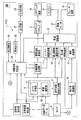
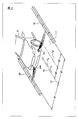
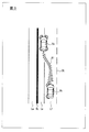
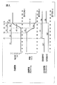
- FIG. 1 is a block diagram showing an embodiment of a vehicle travel control device according to the present invention. It is a figure which shows the state which detects the distance from an own vehicle to a curb, and sets a target route. It is a top view showing a run scene of automatic stop control concerning an embodiment of the present invention. It is a figure which shows the target route in the driving scene shown in FIG. 3, a target vehicle speed profile, and a direction indicator profile.
- FIG. 10 is a plan view showing a traveling scene of conventional automatic vehicle stop control in which deceleration of the host vehicle and movement to the road shoulder are simultaneously performed. It is a block diagram which shows the structure of the automatic vehicle stop control part shown in FIG.
- FIG. 1 is a block diagram showing the configuration of the travel control device VTC according to the present embodiment.
- the travel control device VTC according to the present embodiment is also an embodiment for implementing the vehicle travel control method according to the present invention.
- the travel control device VTC is, for example, an in-vehicle device mounted in a vehicle, and has various functions for controlling travel of the host vehicle V 0 (see FIG. 2) in which the travel control device VTC is mounted.
- the travel control unit VTC in addition to the automatic cruise control function for running automatically the vehicle V 0 toward a destination set, when the vehicle V 0 has arrived at the destination, the vehicle V 0 It is equipped with an automatic stop control function that stops the vehicle from the running lane to the road shoulder.
- the travel control device VTC includes a destination setting unit 1, a vehicle position detection unit 2, a map database 3, a route setting unit 4, a sensor 5, a travelable area generation unit 6, and a target.
- a route setting part 4 a travelable area generation part 6, a target route generation part 7, a route following control part 8, a corner deceleration control part 11, and a vehicle speed adjustment part 12 are provided.
- the stationary obstacle deceleration control unit 16, the stop line vehicle stop control unit 17, the preceding vehicle recognition unit 18, the headway distance control unit 19, the automatic vehicle stop control unit 20, and the self-diagnosis unit 24 are one or more. It is composed of a computer and software installed in the computer.
- the computer includes a ROM that stores a program for causing the above-described units to function, a CPU that executes the program stored in the ROM, and a RAM that functions as an accessible storage device. Note that an MPU, DSP, ASIC, FPGA, or the like can be used instead of or together with the CPU.
- the computer configuring each of the above-mentioned units includes a destination setting unit 1, a vehicle position detection unit 2, a map database 3, a sensor 5, a steering actuator 9, a vehicle speed servo 13, a lighting circuit 21, and an in-vehicle camera.
- a vehicle-mounted LAN such as CAN (Controller Area Network) or the like is connected.
- the destination setting unit 1 sets a destination when the vehicle V 0 travels by the automatic travel control function.
- the destination setting unit 1 includes a display device and an input device.
- the display device is, for example, a display such as a liquid crystal panel, and displays map information read from the map database 3, setting information for setting a destination, and the like.
- the input device is, for example, a device such as a touch panel arranged on a display screen, a dial switch, or a microphone capable of inputting by driver's voice, and is used for input operation of a destination for setting information displayed on the display device. Used.
- the destination setting unit 1 generates destination information indicating the position of the destination based on the map information, the setting information, and the input information input from the input device.
- the host vehicle position detection unit 2 detects the current position of the host vehicle V 0 .
- the vehicle position detection unit 2 includes a GPS unit, a gyro sensor, a vehicle speed sensor and the like.
- the own vehicle position detection unit 2 detects radio waves transmitted from a plurality of satellite communications by the GPS unit, periodically acquires the position information of the own vehicle V 0 , and the acquired position information of the own vehicle V 0 ,
- the current position of the host vehicle V 0 is detected based on the angle change information acquired from the gyro sensor and the speed information acquired from the vehicle speed sensor, and host vehicle position information indicating the current position is generated.
- the map database 3 stores low-precision map information and three-dimensional high-precision map information.
- the low-precision map information is map information used in a general car navigation device and the like, and information about roads is recorded together with position information of various facilities and specific points.
- the road information includes location information such as a confluence point, a branch point, a toll gate, a position where the number of lanes decreases, a service area (SA)/parking area (PA), a road type, a road width, a number of lanes, a road radius, It includes information about roads such as whether there is a dedicated lane for turning right or left, the number of dedicated lanes, and speed limits.
- 3D high-precision map information is 3D map information based on the road shape detected when traveling on an actual road using a data acquisition vehicle, and together with map information, road confluence, branch points, and charges
- the location information, the position where the number of lanes is reduced, and the detailed and highly accurate position information such as the service area/parking area are the map information associated as the three-dimensional information.
- the route setting unit 4 generates a travel route to the destination of the host vehicle V 0 .
- the route setting unit 4 includes a route generation unit 41 and a lane setting unit 42.
- the route generation unit 41 based on the destination information acquired from the destination setting unit 1, the own vehicle position information acquired from the own vehicle position detection unit 2, and the map information acquired from the map database 3, the own vehicle V Generate a travel route from the current position of 0 to the destination.
- the lane setting unit 42 sets the lane in which the host vehicle V 0 travels on the travel route based on the three-dimensional high-precision map information acquired from the map database 3.
- the sensor 5 detects the situation around the vehicle V 0 .
- the sensor 5 includes, for example, a camera, a radar device, and a lidar device.
- the camera is an image sensor that captures image data by imaging a predetermined area in front of the host vehicle V 0 , and is composed of, for example, a CCD wide-angle camera provided above the front window in the vehicle interior.
- the camera may be a stereo camera or an omnidirectional camera, and may include a plurality of image sensors. From the image data captured by the camera, the travel control device VTC identifies roads existing in front of the host vehicle V 0 and structures around the road, road markings, signs, stop lines, other vehicles, motorcycles, bicycles, pedestrians, etc. It is detected as the surrounding situation of the own vehicle V 0 .
- a millimeter wave or ultrasonic is irradiated to the front of the own vehicle V 0 scanning a predetermined range around the vehicle V 0, other vehicles existing around the vehicle V 0, motorcycles, bicycles, Detects obstacles such as pedestrians, curbs on shoulders, guardrails, walls, and embankments.
- the radar apparatus the relative position between the obstacle and the own vehicle V 0 (orientation), the relative velocity of the obstacle, to detect the distance from the vehicle V 0 to the obstacle as a surroundings of the vehicle V 0.
- Rider device other vehicles, motorcycles, bicycles laser light is irradiated to the area around the vehicle V 0 scanning a predetermined range around the vehicle V 0, present around the vehicle V 0, pedestrians, Detects obstacles such as curbstones on road shoulders, guardrails, walls, and embankments.
- the rider device receives the laser light reflected by the surrounding obstacles and three-dimensionally maps the laser light, the relative position (direction) between the obstacle and the own vehicle V 0 , the relative speed of the obstacle, the own vehicle.
- the distance from the vehicle to the obstacle, the shape of the obstacle, and the like are detected as the surrounding condition of the vehicle V 0 .
- the rider devices 51L and 51R are mounted on the left and right sides of the front bumper of the host vehicle V 0 , and the rider devices 51L and 51R allow the shafts along the front-rear direction of the host vehicle V 0 to be mounted.
- obstacles such as curbs SL, SR existing in the left-right direction of the vehicle V 0 are detected.
- the drivable area generation unit 6 generates an area in which the vehicle V 0 can travel within the travel route.
- the drivable area generation unit 6 acquires the travel route from the route setting unit 4, and acquires information about the situation around the host vehicle V 0 from the sensor 5.
- the drivable area generation unit 6 selects another vehicle, a pedestrian, a parked vehicle, or a construction vehicle from the inside of the lane set as the travel route based on the acquired travel route and the information about the situation around the vehicle V 0.
- An area occupied by an obstacle such as a travel-restricted area due to the obstacle is specified, an unoccupied area not occupied by the obstacle is set as a travelable area of the host vehicle V 0 , and travelable area information regarding the set area is generated. To do.
- the target route generation unit 7 generates a target route that is a follow-up target when the host vehicle V 0 travels within the travelable area.
- the target route generation unit 7 acquires the travelable area information from the travelable area generation unit 6, and acquires the information on the situation around the host vehicle V 0 from the sensor 5.
- the target route generation unit 7 extracts the left boundary line and the right boundary line from the travelable area based on the acquired travelable area information and the information about the situation around the host vehicle V 0 , and the left boundary line is extracted.
- a target route is generated in the center of the travelable area that is equidistant from the right boundary line.
- the left curb SL and the right curb SR are used as a left boundary line and a right boundary line, and the lane center line Lc equidistant from the left curb SL and the right curb SR.
- the target route Tp is set above.
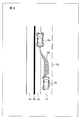
- the route tracking control unit 8 causes the host vehicle V 0 to travel so as to follow the target route Tp. Specifically, as shown in FIG. 2, the route tracking control unit 8 determines that the vehicle center line Vc set along the front-rear direction of the host vehicle V 0 is the target route Tp generated by the target route generation unit 7.
- the steering device 10 is controlled via the steering actuator 9 so as to move up. As a result, the host vehicle V 0 travels along the travel route so as to follow the target route Tp.
- the corner deceleration control unit 11 decelerates the speed of the host vehicle V 0 so that the occupant does not feel uncomfortable when the target route Tp generated by the target route generation unit 7 has a right turn, a left turn, a curve, or the like. To do. Specifically, the corner deceleration control unit 11 acquires the target route Tp from the target route generation unit 7, and sets the speed after deceleration based on the right turn angle, the left turn angle of the target route Tp, the radius of the curve, and the like, The deceleration information regarding the speed after deceleration is input to the vehicle speed adjusting unit 12. The vehicle speed adjustment unit 12 controls the engine 14 and the brake device 15 via the vehicle speed servo 13 based on the deceleration information input from the corner deceleration control unit 11 to reduce the speed of the host vehicle V 0 .
- the stationary obstacle deceleration control unit 16 can avoid a stationary obstacle without giving a feeling of strangeness to an occupant when a traveling control area such as a parked vehicle or construction exists in a lane set as a traveling route.
- the speed of the host vehicle V 0 is reduced.
- the stationary obstacle deceleration control unit 16 acquires the travelable area information from the travelable area generation unit 6 and the information about the situation around the vehicle V 0 from the sensor 5.
- the stationary obstacle deceleration control unit 16 sets the speed after deceleration on the basis of the acquired travelable area information and the information about the situation around the host vehicle V 0 , and sets the speed after deceleration in the vehicle speed adjustment unit 12. Enter deceleration information.
- the vehicle speed adjustment unit 12 controls the engine 14 and the brake device 15 via the vehicle speed servo 13 based on the deceleration information input from the stationary obstacle deceleration control unit 16 to reduce the speed of the host vehicle V 0 .
- the stop line stop control unit 17 stops the own vehicle V 0 according to the stop line when the own vehicle V 0 reaches a temporary stop point such as an intersection. Specifically, the stop line stop control unit 17 determines that the own vehicle V 0 is an intersection or the like based on the own vehicle position information acquired from the own vehicle position detection unit 2 and the traveling route set by the route setting unit 4. The position of the stop lane is detected by the camera of the sensor 5 while determining that the vehicle has reached Then, the stop line stop control unit 17 controls the engine 14 and the brake device 15 via the vehicle speed servo 13 by the vehicle speed adjustment unit 12 to stop the host vehicle V 0 in line with the stop line.
- the preceding vehicle recognizing unit 18 and the following distance control unit 19 determine the speed of the own vehicle V 0 in order to maintain a predetermined distance between the preceding vehicle and the preceding vehicle. Slow down. Specifically, the preceding vehicle recognizing unit 18 recognizes the preceding vehicle based on the surrounding situation detected by the radar device of the sensor 5, and determines the distance between the preceding vehicle and the host vehicle V 0 and the relative speed with respect to the preceding vehicle. Is calculated, and the calculation result is input to the following distance control unit 19 as the following distance information and the relative speed information.
- the inter-vehicle control unit 19 Based on the inter-vehicle distance information and the relative speed information distance information input from the preceding vehicle recognizing unit 18, the inter-vehicle control unit 19 causes the vehicle speed adjusting unit 12 to set the vehicle speed so that a predetermined inter-vehicle distance is provided between the preceding vehicle and the preceding vehicle.
- the engine 14 and the brake device 15 are controlled via the servo 13.
- Automatic stopping control unit 20 travel during traveling of the vehicle V 0, when the vehicle V 0 has arrived at the destination, or if the driver of the host vehicle V 0 is no longer performed operation, or to the host vehicle V 0 When a failure that hinders the vehicle occurs, an automatic stop control for stopping the own vehicle V 0 on the road shoulder is executed.
- FIG. 3 shows a driving scene in which the vehicle V 0 traveling on the left-lane, one-lane road is stopped from the lane L1 to the left shoulder Ls by the automatic vehicle stop control according to the present embodiment.
- the symbols SL, Lw, and CL shown in the figure indicate a curb provided at the left end of the road shoulder Ls, a sidewalk provided to the left of the road shoulder Ls, and a center line of the one-lane road.
- the host vehicle V 01 indicates the host vehicle V 0 after completion of the automatic vehicle stop control.
- Arrow line A1 depicted ahead of the host vehicle V 0 indicates a movement path of the vehicle V 0 in the automatic stop control
- the amplitude of the arrow A1 indicates the speed of the vehicle V 0 by the width .. That is, the larger the amplitude of the arrow A1, the faster the speed of the host vehicle V 0 , and the smaller the amplitude, the slower the speed.
- FIG. 4 shows a target route of the automatic vehicle stop control in the above-mentioned traveling scene, a target vehicle speed profile, and a turn signal profile.
- the target route is the target route Tp generated by the target route generation unit 7.
- the target vehicle speed profile indicates the speed change of the host vehicle V 0 adjusted by the vehicle speed adjusting unit 12.
- the direction indicator profile indicates the timing and the operation content of operating the direction indicator 22 by the lighting circuit 21.
- the movement of the host vehicle V 0 from the lane L 1 to the road shoulder Ls is a movement of approaching the road edge, so that the occupant may feel a sense of discomfort depending on the movement speed or the like.
- the traveling scene shown in FIG. 5 shows a conventional traveling scene in which deceleration of the host vehicle V 0 and movement to the road shoulder Ls are simultaneously executed.
- the speed at which the vehicle V 0 moves to the road shoulder Ls may be faster than the occupant's expectation. In such a case, The passengers may feel a lot of discomfort.
- the automatic stop control according to this embodiment the traffic situation illustrated in FIG. 3, as seen from the target path and the target vehicle speed profile shown in FIG. 4, after decelerating the speed of the vehicle V 0, the vehicle It has been moved to the shoulder Ls the V 0 from the lane L1. That is, the automatic stop control according to this embodiment, the speed of the vehicle V 0 advance sufficiently decelerated, moving at speed after decelerating the host vehicle V 0 from the lane L1 to shoulder Ls, moving to shoulder Ls Some keep the speed constant.
- the speed at which the vehicle V 0 is moved to the shoulder Ls is lowered, since not occur sway due speed change, self without causing discomfort to the occupants
- the vehicle V 0 can be stopped at the shoulder Ls.
- the direction indicator 22 is operated before a predetermined time before the host vehicle V 0 starts deceleration, and the road shoulder Ls is stopped.
- the other vehicle behind is notified of the stop.
- the turn-on indicators 22 are shown at the four corners of the host vehicles V 0 and V 01 .
- an automatic stop control is configured by combining a plurality of types of control, and the automatic vehicle stop control is executed by sequentially executing each control individually. ..
- an automatic stop control according to this embodiment includes a direction indicator control C1 to execute a direction instruction to shoulder Ls to the vehicle V 0, the deceleration control C2 to decelerate the speed of the vehicle V 0 , and biassing the control C3 is moved to the shoulder Ls from the lane L1 traveling the vehicle V 0, the stopping control C4 to stop the vehicle V 0 to shoulder Ls, is constituted by.
- the automatic vehicle stop control unit 20 generates a control plan including execution contents and execution timings of these controls, and sequentially executes each control individually according to the generated control plan, whereby the automatic stop according to the present embodiment is performed. Car stop control is executed.
- the automatic vehicle stop control according to the present embodiment has a plurality of vehicle stop modes in order to perform optimal vehicle stop control according to the purpose of stopping the host vehicle V 0 .
- the dressing mode is executed, and when the driver of the host vehicle V 0 cannot drive, or when the host vehicle V 0 is An emergency stop mode that is executed when a failure that hinders running occurs is provided.
- the dressing mode and the emergency stop mode according to the present embodiment correspond to the first mode and the second mode according to the present invention.
- the vehicle motion generated in the host vehicle V 0 during the automatic vehicle stop control is different between the normal landing mode and the emergency vehicle stop mode of the automatic vehicle stop control.
- the vehicle motion is a physical quantity generated in the host vehicle V 0 when the host vehicle V 0 is stopped on the road shoulder Ls, and, for example, a negative acceleration (hereinafter, deceleration) generated when the host vehicle V 0 is decelerated. (Also referred to as “.”), or the speed, lateral speed, lateral acceleration, etc. when moving the vehicle V 0 to the road shoulder Ls.
- the control vehicle In the normal-arrival mode in which the host vehicle V 0 stops at a preset destination, the control vehicle has a sufficient time to control, so that the host vehicle V 0 is compared so as not to make the occupants of the host vehicle V 0 feel uncomfortable. The vehicle slowly stops to stop at the shoulder Ls.
- the emergency stop mode since it is necessary to stop the host vehicle V 0 quickly, there is a possibility that the vehicle motion (large vehicle state change) is faster than that in the normal landing mode and the occupant may feel discomfort. Even if there is, the host vehicle V 0 is stopped at the road shoulder Ls so that the sense of discomfort is reduced.
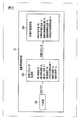
- the automatic vehicle stop control unit 20 includes a determination unit 201, a control parameter determination unit 202, and a control plan calculation unit 203.
- the determination unit 201 determines whether or not the host vehicle V 0 is to execute the automatic stop control. Specifically, the determination unit 201 determines the destination information acquired from the destination setting unit 1, the vehicle position information acquired from the vehicle position detection unit 2, and the travelable area acquired from the travelable area generation unit 6. Based on the information, when the host vehicle V 0 approaches the destination within the predetermined distance, it is determined that the automatic stop control needs to be executed.
- the determination unit 201 also determines whether or not the driver can drive, based on the image data input from the in-vehicle camera 23 shown in FIG.
- the in-vehicle camera 23 is an image sensor that captures image data by imaging the upper half of the driver's body, and is, for example, a CCD wide-angle camera provided above the front window in the vehicle interior.
- the determination unit 201 analyzes the image data of the in-vehicle camera 23, and determines from the analysis result that the automatic stop control needs to be executed when it is found that the driver is dozing.
- the actions other than the driving of the vehicle performed by the driver include, for example, an action of listening to an image displayed on the display device of the vehicle V 0 , an action of making a call with a mobile phone, a mobile device such as a smartphone. This includes operations such as operations, reading and eating and drinking.
- Image data from the in-vehicle camera 23 can be used to detect these actions, as in the case of falling asleep.
- the determination unit 201 determines whether or not there is a failure in the host vehicle V 0 that hinders traveling, based on the diagnosis result of the self-diagnosis unit 24 shown in FIG. 1.
- the self-diagnosis unit 24 is also called an OBD (On Board Diagnostic), and is mounted on the vehicle for diagnosing an abnormality or failure of each unit of the vehicle and displaying the diagnosis result on an instrument panel or the like.
- the determination unit 201 determines that it is necessary to execute the automatic stop control when the self-diagnosis unit 24 finds a failure or abnormality in the vehicle V 0 that hinders traveling.
- the determination unit 201 When the host vehicle V 0 arrives at the destination, the determination unit 201 inputs the determination flag “1” to the control parameter determination unit 202 in order to execute the automatic stop control in the normal arrival mode. In addition, the determination unit 201 executes the automatic stop control in the emergency stop mode when the driver cannot drive, or when the vehicle V 0 has a failure that hinders traveling. The determination flag “0” is input to the control parameter determination unit 202.
- the control parameter determination unit 202 generates control parameters used to generate a control plan for automatic vehicle stop control according to this embodiment.
- the control parameter determination unit 202 determines the control parameters for the dressing mode. Further, when the determination flag “0” is input from the determination unit 201, the control parameter determination unit 202 determines the control parameter for the emergency stop mode.
- the control parameter determination unit 202 uses, as control parameters, the first deceleration G1, the maximum lateral acceleration GL, the maximum yaw angle ⁇ Y, the second deceleration G2, the direction instruction control start time T1, and the pulling speed Vw. , Width adjustment time Tw are determined.
- the second deceleration G2 is a deceleration when decelerating the host vehicle V 0 traveling in the lane L1 in the deceleration control C2.
- the second deceleration G2 is preset and stored in the ROM or the like in order to decelerate the host vehicle V 0 so as not to give an occupant a feeling of strangeness.
- the second deceleration G2 is set in advance to the second deceleration G2a for the normal landing mode and the second deceleration G2b for the emergency stop mode.
- the second deceleration G2a and the second deceleration G2b have different set values, for example, second deceleration G2a ⁇ second deceleration G2b.
- the maximum lateral acceleration GL is the maximum lateral acceleration when the host vehicle V 0 is moved from the lane L1 to the road shoulder Ls in the width-shifting control C3.
- the maximum lateral acceleration GL when moving the host vehicle V 0 to the road shoulder Ls is set in advance in order to move the host vehicle V 0 to the road shoulder Ls so that the occupant does not feel uncomfortable. It is stored in the ROM or the like.
- the maximum lateral acceleration GL is set in advance to the maximum lateral acceleration GLa for the normal landing mode and the maximum lateral acceleration GLb for the emergency stop mode.
- the maximum lateral acceleration GLa and the maximum lateral acceleration GLb have different set values, for example, maximum lateral acceleration GLa ⁇ maximum lateral acceleration GLb.
- the maximum yaw angle ⁇ Y is the maximum yaw angle with respect to the direction in which the lane L1 extends when the vehicle V 0 is moved from the lane L1 to the road shoulder Ls in the width-shifting control C3.
- the maximum yaw angle ⁇ Y when moving the host vehicle V 0 to the road shoulder Ls is set in advance in order to move the host vehicle V 0 to the road shoulder Ls so that the occupant does not feel uncomfortable. It is stored in the ROM or the like.
- the maximum yaw angle ⁇ Y is set in advance to the maximum yaw angle ⁇ Ya for the normal landing mode and the maximum yaw angle ⁇ Yb for the emergency stop mode.
- the maximum yaw angle ⁇ Ya and the maximum yaw angle ⁇ Yb have different set values, for example, maximum yaw angle ⁇ Ya ⁇ maximum yaw angle ⁇ Yb.
- the first deceleration G1 is a deceleration when the vehicle V 0 traveling on the road shoulder Ls is stopped in the vehicle stop control C4.
- Automatic stop control stores in order to decelerate the host vehicle V 0 so as not to give uncomfortable feeling to the occupant of the vehicle V 0, it sets the first deceleration G1 in advance in a ROM or the like .
- the first deceleration G1 is set in advance to the first deceleration G1a for the normal landing mode and the first deceleration G1b for the emergency vehicle stop mode.
- the first deceleration G1a and the first deceleration G1b have different set values, for example, the first deceleration G1a ⁇ the first deceleration G1b.
- the host vehicle V 0 stops more slowly than in the emergency stop mode.
- the change in speed in the vehicle front-rear direction as the change in the state of the host vehicle V 0 is larger than in the deceleration control C4 in the normal landing mode.
- the direction instruction control start time T1 is set in advance as a time period before the deceleration control C2 is started, based on the deceleration control C2.
- the direction instruction control start time T1a for the normal landing mode and the direction instruction control start time T1b for the emergency stop mode are set in advance and stored in the ROM or the like. Stored in.
- the direction instruction control start time T1a and the direction instruction control start time T1b have different set values, and for example, the direction instruction control start time T1a ⁇ the direction instruction control start time T1b.
- the crossing speed Vw is the speed of the host vehicle V 0 during the crossing control C3.
- lateral move speed Vw Is also the target speed in the deceleration control C2.
- the vehicle stop control C4 is started after the width-shift control C3 maintained at a constant speed, so the width-shift speed Vw is also the vehicle speed at the start of the vehicle stop control C4.
- the approaching speed Vw is set to a relatively slow speed in order to stop the host vehicle V 0 on the road shoulder Ls so that the occupant does not feel uncomfortable.
- the width-shifting speed Vw in the present embodiment is a speed that maintains the speed after deceleration, but the width-shifting speed Vw may change to such an extent that the occupant does not feel uncomfortable, and may be a substantially constant speed. ..
- the control parameter determination unit 202 sets the width shifting speed Vw as follows. As shown in FIG. 2, the control parameter determination unit 202 acquires the distance W1 between the host vehicle V 0 and the left curb SL from the rider device 51L of the sensor 5. Then, the control parameter determination unit 202, a distance W1 obtained, based on a predetermined biassing interval W2 provided between the vehicle center line Vc and curb SL of the vehicle V 0 after the centering control C3, self The width-shift amount W3 required to move the vehicle V 0 to the road shoulder Ls is calculated.
- control parameter determination unit 202 moves the host vehicle V 0 to the road shoulder Ls based on the calculated width-shifting amount W3 and the maximum yaw angle ⁇ Y determined according to the mode of the control plan to be generated. calculating a traveling distance required, and the running distance, the biassing weight W3, based on the maximum lateral acceleration GL that is determined in accordance with the mode of the control plan to be generated, the centering control C3 at the vehicle V 0 Estimate the lateral velocity and lateral acceleration that occur in the. Then, the control parameter determination unit 202 calculates the lateral shifting speed Vw based on the estimated lateral velocity and lateral acceleration and the aforementioned lateral shifting interval W2.
- the width adjustment time Tw is an execution time required for the width adjustment control C3.
- an appropriate length of time Tw is set in order to stop the vehicle V 0 on the road shoulder Ls so as not to give an occupant an uncomfortable feeling.
- the width-shifting time Tw is calculated based on the lateral velocity and lateral acceleration estimated for setting the width-shifting speed Vw and the aforementioned width-shifting interval W2.
- the control parameter determination unit 202 determines the control parameters determined according to the determination flag, that is, the first deceleration G1, the maximum lateral acceleration GL, the maximum yaw angle ⁇ Y, the second deceleration G2, and the direction instruction control start time. T1, the width adjustment speed Vw, and the width adjustment time Tw are input to the control plan calculation unit 203.
- the control plan calculation unit 203 generates a control plan for automatic vehicle stop control according to the present embodiment based on the control parameters input from the control parameter determination unit 202.
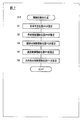
- the flowchart shown in FIG. 7 shows a procedure for generating a control plan for automatic vehicle stop control according to the present embodiment.
- the control plan calculation unit 203 sets the planned stop position P5 shown in FIG. 4 according to the determination flag input from the determination unit 201. For example, when the determination flag input from the determination unit 201 is the determination flag “1” indicating the arrival at the destination, the control plan calculation unit 203 acquires the destination information from the destination setting unit 1. The travelable area information is acquired from the travelable area generation unit 6. The control plan calculation unit 203 sets a planned stop position where the host vehicle V 0 is stopped in the normal landing mode, based on the acquired destination information and travelable area information.
- the control plan calculation unit 203 detects a road shoulder Ls at which a vehicle can be parked or stopped near the destination, and detects a parked vehicle or the like from the detected road shoulder Ls. A position not occupied by an obstacle is set as the planned stop position P5.
- the control plan calculation unit 203 sets the bus stop provided on the route of the route bus as the planned stop position P5.
- the control plan calculation unit 203 determines that the vehicle position detection unit 2 has detected that The position information is acquired, and the travelable area information is acquired from the travelable area generation unit 6.
- the control plan calculation unit 203 detects a road shoulder Ls on which the vehicle can be parked and stopped based on the acquired own vehicle position information and the travelable area information, and occupancy by an obstacle such as a parked vehicle is detected from the detected road shoulder Ls.
- a position that does not exist is set as the planned stop position P5.
- the control plan calculation part 203 sets the vehicle stop control start position P4 shown in FIG. 4 in the following step S2. Based on the first deceleration G1 input from the control parameter determination unit 202 and the approaching speed Vw, the control plan calculating unit 203 sets the own vehicle V 0 traveling at the approaching speed Vw at the first deceleration G1. A stop distance H1 required for decelerating and stopping is calculated. In addition, the control plan calculation unit 203, based on the calculated vehicle stop distance H1 and the planned vehicle stop position P5 set in step S1, the vehicle stop control start position P4 before the planned vehicle stop position P5 by the vehicle stop distance H1. To set.
- the control plan calculation unit 203 sets the width-shift control start position P3 shown in FIG.
- the control plan calculation unit 203 has a travel distance required to move the host vehicle V 0 from the lane L1 to the shoulder Ls based on the approaching speed Vw and the approaching time Tw input from the control parameter determining unit 202.
- the width-shifting distance H2 is calculated.
- the control plan calculation unit 203 sets the width to a position before the vehicle stop control start position P4 by the width-shift distance H2 based on the calculated width-shift distance H2 and the vehicle-stop control start position P4 set in step S2.
- the shift control start position P3 is set.
- the control plan calculation unit 203 sets the deceleration control start position P2 shown in FIG.
- the control plan calculation unit 203 based on the second deceleration G2 input from the control parameter determination unit 202 and the current vehicle speed of the own vehicle V 0 acquired from the vehicle speed sensor of the own vehicle position detection unit 2, A deceleration distance H3 necessary for decelerating V 0 to the width-shifting speed Vw is calculated.
- the control plan calculation unit 203 sets the position before the width reduction control start position P3 by the deceleration distance H3 based on the calculated deceleration distance H3 and the width adjustment control start position P3 set in step S3.
- the deceleration control start position P2 is set.
- the control plan calculation unit 203 sets the direction instruction control start position P1 shown in FIG.
- the control plan calculation unit 203 acquires the direction instruction control start time T1 input from the control parameter determination unit 202, the deceleration control start position P2 set in step S4, and the vehicle speed sensor of the vehicle position detection unit 2. based on the current speed of the vehicle V 0, the timing at which the host vehicle V 0 reaches the deceleration control start position P2, sets the direction indication control start position P1 to the position where the front only in the direction indicated control start time T1 ..
- the automatic vehicle stop control it may be necessary to regenerate the control plan due to changes in surrounding conditions that occur after the control plan is generated. For example, if another vehicle is stopped at the planned stop position P5 after the control plan is generated, it is necessary to reset the planned stop position P5, and the positions P1 to P4 set based on the planned stop position P5 are reset. Settings are also required. Further, if a stationary obstacle, a preceding vehicle, or the like appears on the traveling route up to the planned stop position P5 after the control plan is generated, the speed of the host vehicle V 0 is decelerated, so that the control plan needs to be regenerated. May be. When such a situation in which the control plan needs to be regenerated, the control plan calculation unit 203 regenerates the control plan each time.
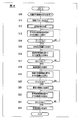
- Determination unit 201 of the automatic stopping control unit 20 determines in a first step S10, whether or not it is necessary to perform automatic stopping control at the vehicle V 0. Specifically, the determination unit 201 determines whether the host vehicle V 0 arrives at the destination, or the driver of the host vehicle V 0 cannot drive, or causes the host vehicle V 0 to interfere with traveling. If such a failure occurs, it is determined that the automatic vehicle stop control needs to be executed.
- the determination unit 201 inputs the determination flag “1” to the control parameter determination unit 202 when the host vehicle V 0 arrives at the destination. In addition, the determination unit 201 sets the determination flag “0” to the control parameter determination unit 202 when the driver cannot drive or when the vehicle V 0 has a failure that hinders traveling. input. Note that when the determination unit 201 determines that it is not necessary to execute the automatic vehicle stop control with the host vehicle V 0 , the determination flag is not input to the control parameter determination unit 202.
- step S10 the control parameter determination unit 202 of the automatic vehicle stop control unit 20 determines the control parameter for the normal landing mode or the emergency vehicle stop mode.
- the control parameter determination unit 202 determines the determined first deceleration G1, maximum lateral acceleration GL, maximum yaw angle ⁇ Y, second deceleration G2, direction instruction control start time T1, width shifting speed Vw, and width.
- the shift time Tw is input to the control plan calculation unit 203.
- the control plan calculation unit 203 of the automatic stop control unit 20 generates a control plan for automatic stop control in the next step S12. Specifically, the control plan calculation unit 203 sets the planned stop position P5 according to the flowchart shown in FIG. 8, and based on the planned stop position P5 and each control parameter, the stop control start position P4 and the width adjustment. The control start position P3, the deceleration control start position P2, and the direction instruction control start position P1 are set.
- control plan calculation unit 203 executes the automatic vehicle stop control based on the generated control plan.
- the control plan calculation unit 203 acquires the own vehicle position information from the own vehicle position detection unit 2 and the travelable area information from the travelable area generation unit 6 to control the direction from the current position.
- the distance D1 to the start position P1 is calculated.
- the control plan calculation unit 203 compares the calculated distance D1 with a preset predetermined distance D1th, and when the host vehicle V 0 reaches a position where the distance D1 is less than the predetermined distance D1th. Then, the process proceeds to the next step S15 to execute the direction control C1.
- the predetermined distance D1th is set in consideration of a time lag from when the execution of the direction instruction control C1 is instructed to when the direction instruction control C1 is actually executed.
- the control plan calculation unit 203 controls the lighting circuit 21 to turn on the left indicator light of the direction indicator 22.
- step S13 the direction instruction control start position P1 and the distance are calculated based on the regenerated control plan.
- D1 is updated, and in step S14, the arrival of the host vehicle V 0 at the updated direction instruction control start position P1 is determined.
- the control plan calculation unit 203 acquires the vehicle position information from the vehicle position detection unit 2 and the travelable area information from the travelable area generation unit 6, and starts deceleration control from the current position.
- the distance D2 to the position P2 is calculated.
- the control plan calculation unit 203 compares the calculated distance D2 with a preset predetermined distance D2th, and when the host vehicle V 0 reaches a position where the distance D2 is less than the predetermined distance D2th. Then, the process proceeds to the next step S18 to execute the deceleration control C2.
- the predetermined distance D2th is set in consideration of the time lag from the instruction to execute the deceleration control C2 to the actual execution.
- control plan calculation unit 203 controls the engine 14 and the brake device 15 via the vehicle speed adjustment unit 12 and the vehicle speed servo 13 to control the own vehicle V 0 at the first deceleration G1.
- the speed is reduced to the width-shifting speed Vw.
- step S16 When the control plan calculation unit 203 regenerates the control plan during execution of steps S16 to S17, in step S16, the deceleration control start position P2 and the distance D2 are calculated based on the regenerated control plan. Are updated, and in step S17, the arrival of the host vehicle V 0 at the updated deceleration control start position P2 is determined.
- the control plan calculation unit 203 acquires the own vehicle position information from the own vehicle position detection unit 2 and the travelable region information from the travelable region generation unit 6, and performs the width adjustment control from the current position.
- the distance D3 to the start position P3 is calculated.
- the control plan calculation unit 203 compares the calculated distance D3 with a preset predetermined distance D3th, and when the host vehicle V 0 reaches a position where the distance D3 is less than the predetermined distance D3th. Then, the process proceeds to the next step S21 to execute the width-shifting control C3.
- the predetermined distance D3th is set in consideration of the time lag from when the execution of the width adjustment control C3 is instructed to when the width adjustment control C3 is actually executed.
- the control plan calculation unit 203 causes the target route generation unit 7 to change the target route Tp, and causes the route following control unit 8 to follow the own vehicle V 0 to the changed target route Tp.
- the host vehicle V 0 is moved to the road shoulder Ls.
- the control plan calculation unit 203 repeatedly detects the distance W1 from the host vehicle V 0 to the curb SL by the rider device 51L of the sensor 5 during execution of the width-shift control C3, as shown in FIG. ..
- the control plan calculation unit 203 updates the target route Tp at any time based on the detected distance W1 so as to obtain a predetermined widthwise spacing W2 between the host vehicle V 0 and the curb SL, and this update is performed.
- the steering device 10 is controlled via the steering actuator 9 so that the host vehicle V 0 follows the target route Tp.
- step S21 the following width adjustment control C3 may be executed.
- the control plan calculation unit 203 detects the distance W1 from the host vehicle V 0 to the curb SL by the rider device 51L of the sensor 5, and detects the detected distance W1, the host vehicle V 0 and the curb SL.
- the width adjustment amount W3 is calculated on the basis of a predetermined width adjustment distance W2 provided between and. Then, the control plan calculation unit 203 sets the final target route Tp1 at a position corresponding to the width shift amount W3.
- the control plan calculation unit 203 causes the target route generation unit 7 to parallel the target route Tp set along the lane center line Lc of the lane L1 in which the host vehicle V 0 travels to the lane center line Lc.
- the vehicle is gradually moved toward the final target route Tp1.
- Path following control unit 8 as the vehicle V 0 follows the target path Tp to gradually move toward the final target path Tp1, and controls the steering device 10 via the steering actuator 9, the vehicle V 0 Moves from the running lane L1 to the shoulder Ls and is stopped parallel to the lane L1.
- step S19 the width-shift control start position P3 and the distance are calculated based on the regenerated control plan.
- D3 is updated, and in step S20, the arrival of the host vehicle V 0 at the updated width-shift control start position P3 is determined.
- the control plan calculation unit 203 acquires the own vehicle position information from the own vehicle position detection unit 2 and the travelable area information from the travelable area generation unit 6, and starts the vehicle stop control from the current position.
- the distance D4 to the position P4 is calculated.
- the control plan calculation unit 203 compares the calculated distance D4 with a preset predetermined distance D4th, and when the host vehicle V 0 reaches a position where the distance D4 is less than the predetermined distance D4th.
- the vehicle stop control C4 is executed.
- the predetermined distance D4th is set in consideration of a time lag from when the vehicle stop control C4 is instructed to be executed to when the vehicle stop control C4 is actually executed.
- control plan calculation unit 203 controls the engine 14 and the brake device 15 via the vehicle speed adjustment unit 12 and the vehicle speed servo 13 so that the host vehicle V 0 is driven at the second deceleration G2. Decelerate and stop.
- step S22 If the control plan calculation unit 203 regenerates the control plan during execution of steps S22 to S23, in step S22, the vehicle stop control start position P4 and the distance D4 are determined based on the regenerated control plan. Are updated, and in step S23, the arrival of the host vehicle V 0 at the updated vehicle stop control start position P4 is determined.
- the stop control C4 is finished vehicle V 0 is stopped to stop scheduled position P5, and continuously performs direction indicator control C1, the right indicator light direction indicator 22 Light up.
- the direction indicator 22 operates as a hazard lamp, it is possible to notify other vehicles behind the vehicle of stopping at the road shoulder Ls.
- FIG. 9(A) shows a target vehicle speed profile (vehicle speed), a target route and TTLC (time to lateral correction) of the automatic vehicle stop control according to the present embodiment
- FIG. 9(B) shows the conventional vehicle speed control shown in FIG.
- the target vehicle speed profile of the automatic vehicle stop control, the target route, and the TTLC are shown.
- TTLC is a margin time until a vehicle moving in the lateral direction collides with an obstacle existing at a moving destination, and a distance (lateral distance) from the vehicle to the obstacle is defined as a relative speed between the vehicle and the obstacle. It is the value divided by.
- the reciprocal number of TTLC (1/TTLC) is used as the risk degree indicating the degree of the approach risk of the host vehicle V 0 to the obstacle.
- the risk degree is about 1 ⁇ 4 s ⁇ 1 .
- the risk degree is approximately 1/9 s -1 , so that the risk degree can be reduced by 55% as compared with the conventional automatic vehicle stop control.
- the travel control unit VTC and travel control method for a vehicle As described above, according to the travel control unit VTC and travel control method for a vehicle according to the present embodiment, during traveling of the vehicle V 0, when the vehicle V 0 has arrived at the destination, or the vehicle V 0 When the driver becomes unable to drive, or when the vehicle V 0 has a trouble that hinders traveling, the automatic stop control for stopping the vehicle V 0 on the shoulder Ls is executed.
- shoulder and deceleration control C2 and biassing the control C3 is moved to the shoulder Ls from the lane L1 traveling the vehicle V 0, the vehicle V 0
- this automatic stop control is to decelerate the speed of the vehicle V 0
- a control plan for automatic vehicle stop control including a vehicle stop control C4 for stopping at Ls is generated, and a deceleration control C2, a width-shifting control C3, and a vehicle stop control C4 are individually and sequentially executed based on the control plan.
- the automatic vehicle stop control is executed so that the host vehicle V 0 is decelerated and then moved to the road shoulder.
- the speed at which the host vehicle V 0 approaches the road shoulder Ls can be suppressed to a low speed, so that it is possible to execute the automatic stop control so that the occupant of the host vehicle V 0 does not feel uncomfortable.
- the speed of the host vehicle V 0 is maintained at a constant speed when the width-shift control C3 is executed.
- the width-shift control C3 is executed.
- a control plan for the dressing mode (first mode) is generated, If the driver is no longer performed operation, or when a failure for hindering the traveling of the host vehicle V 0 is generated, the vehicle V 0 while a large change in the vehicle relative to the control plan of the positive wearing mode Generates a control plan for an emergency stop mode (second mode) in which the vehicle stops at the road shoulder Ls. Accordingly, the control plan for the automatic stop control can be generated in the optimum mode according to the purpose of stopping the host vehicle V 0 on the road shoulder Ls, and therefore the automatic stop control is executed so as not to make the occupant feel uncomfortable. It becomes possible.
- Control C1 is included.
- traveling control unit VTC and travel control method for a vehicle in order to set the width shifting speed Vw is the speed of the vehicle V 0 which at the centering control C3, from the vehicle V 0 detecting the distance W1 to the curb SL is an end of the shoulder Ls, the host from the vehicle V 0 and the distance W1 to the curb SL, given provided between the vehicle V 0 and curb SL after the centering control C3 based on the lateral move distance W2, to calculate the biassing weight W3 required to move the vehicle V 0 to shoulder Ls, based on the width shift amount W3, the centering control C3 sometimes generated in the subject vehicle V 0 Then, the lateral speed and lateral acceleration are estimated, and the lateral speed Vw is set based on the estimated lateral speed and lateral acceleration and the lateral spacing W2.
- the width-shifting speed Vw when moving the host vehicle V 0 to the road shoulder Ls can be set to an optimum speed that does not give an occupant
- the width adjustment time Tw required for the width adjustment control is set to the lateral velocity and lateral acceleration estimated from the width adjustment amount W3, and the width adjustment interval. Since it is set based on W2, it is possible to set the width-adjustment time Tw for moving the vehicle V 0 to the road shoulder Ls to an optimum time that does not give an occupant a feeling of discomfort.
- traveling control unit VTC and travel control method for a vehicle in order to generate a control plan, according to the mode control schedule, set the stop expected position P5 to stop the vehicle V 0 To do. Then, depending on the mode of the control plan, to set the first deceleration G1 which is generated and stopping control C4 at the vehicle V 0, a lateral move speed Vw, based on the first deceleration G1, biassing speed The stop distance H1 required to stop the host vehicle V 0 traveling at Vw is calculated, and the stop control start position P4 is set based on the stop distance H1 and the planned stop position P5.
- a lateral move speed Vw based on the lateral move time Tw, the vehicle V 0 calculates the biassing distance H2 is travel distance required to move to the shoulder Ls, and the centering distance H2, stop
- the width-shift control start position P3 is set based on the control start position P4.
- the planned stop position P5 the stop control start position P4, the width-shift control start position P3, and the deceleration control start position P2 are set based on the planned stop position P5. Since the control plan can be generated so that each control is individually and sequentially performed, it is possible to execute the automatic stop control so that the occupant does not feel uncomfortable.
- the deceleration control C2 is started to control the host vehicle V 0 .
- the width-shifting control C3 is started to set the host vehicle V 0 at the width-shifting speed Vw.
- the stop control C4 is started to decelerate the host vehicle V 0 traveling at the approaching speed Vw at the first deceleration G1.
- the deceleration control C2, the width reduction control C3, and the vehicle stop control C4 are individually and sequentially executed at the deceleration control start position P2, the width reduction control start position P3, and the vehicle stop control start position P4 that are set in the control plan. Therefore, the automatic stop control can be executed as a whole by smoothly executing each control. Therefore, it is possible to execute the automatic stop control so that the occupant does not feel uncomfortable.
- traveling control unit VTC and travel control method for a vehicle according to the present embodiment, to detect the distance W1 from the vehicle V 0 after the start of the centering control C3 to curb SL is an end of the shoulder Ls, as predetermined biassing spacing W2 between the vehicle V 0 and curb SL is obtained, to move the vehicle V 0 to shoulder Ls. Therefore, the width-shifting control C3 can be performed while always properly maintaining the distance between the host vehicle V 0 and the curb SL, so that the automatic stop control can be executed so as not to give an occupant an uncomfortable feeling.
- the lateral shift control C3 determines the final target route for stopping the host vehicle V 0 on the shoulder Ls based on the lateral shift amount W3.
- the target route Tp set along the lane center line Lc of the lane L1 on which the host vehicle V 0 travels is gradually moved toward the final target route Tp1 in a state parallel to the lane center line Lc. Then, the host vehicle V 0 is caused to follow the gradually moved target route Tp.
- the own vehicle V 0 is smoothly moved to the shoulder Ls, and the own vehicle V 0 is parallel to the lane L1. Can be stopped. Therefore, it is possible to execute the automatic stop control so that the occupant does not feel uncomfortable.
- the control plan is regenerated when the situation around the host vehicle V 0 changes during execution of the automatic stop control. , Execute automatic stop control based on the regenerated control plan. As a result, even when the situation around the host vehicle V 0 changes, the host vehicle V 0 can be appropriately stopped at the road shoulder Ls, so that the automatic stop control can be executed so as not to make the occupant feel uncomfortable. It will be possible.
- the same emergency stop mode control plan is used when the driver of the host vehicle V 0 cannot drive and when the host vehicle V 0 has a failure that hinders traveling.
- a stop mode in which the host vehicle V 0 is stopped by a vehicle motion different from that in the case where the host vehicle V 0 has a trouble that hinders traveling when the driver cannot drive the vehicle. May be set.
Abstract
Si un véhicule (V0) arrive à une destination tandis que le véhicule (V0) se déplace, ou si le conducteur du véhicule (V0) ne peut pas conduire, ou en cas de défaillance qui peut interférer avec le déplacement du véhicule (V0), un plan de commande est généré pour une commande d'arrêt automatique comprenant une commande de décélération (C2) pour réduire la vitesse du véhicule (V0), une commande de décalage latéral (C3) pour déplacer le véhicule (V0) de la voie (L1) sur laquelle le véhicule se déplace vers un accotement de route (Ls), et une commande d'arrêt (C4) pour arrêter le véhicule (V0) sur l'accotement de route (Ls), et sur la base du plan de commande, la commande de décélération (C2), la commande de décalage latéral (C3) et la commande d'arrêt de véhicule (C4) sont exécutées individuellement et séquentiellement, ce qui permet d'exécuter la commande d'arrêt automatique de telle sorte que le véhicule (V0) est amené à décélérer puis est déplacé vers l'accotement de route (Ls).
Priority Applications (5)
| Application Number | Priority Date | Filing Date | Title |
|---|---|---|---|
| JP2020568859A JP7250825B2 (ja) | 2019-01-31 | 2019-01-31 | 車両の走行制御方法及び走行制御装置 |
| PCT/IB2019/000120 WO2020157533A1 (fr) | 2019-01-31 | 2019-01-31 | Procédé de commande de déplacement et dispositif de commande de déplacement pour véhicule |
| EP19912204.5A EP3919336B1 (fr) | 2019-01-31 | 2019-01-31 | Procédé de commande de déplacement et dispositif de commande de déplacement pour véhicule |
| CN201980090864.8A CN113365894B (zh) | 2019-01-31 | 2019-01-31 | 车辆的行驶控制方法及行驶控制装置 |
| US17/310,336 US20220063669A1 (en) | 2019-01-31 | 2019-01-31 | Travel Control Method and Travel Control Device for Vehicle |
Applications Claiming Priority (1)
| Application Number | Priority Date | Filing Date | Title |
|---|---|---|---|
| PCT/IB2019/000120 WO2020157533A1 (fr) | 2019-01-31 | 2019-01-31 | Procédé de commande de déplacement et dispositif de commande de déplacement pour véhicule |
Publications (1)
| Publication Number | Publication Date |
|---|---|
| WO2020157533A1 true WO2020157533A1 (fr) | 2020-08-06 |
Family
ID=71841405
Family Applications (1)
| Application Number | Title | Priority Date | Filing Date |
|---|---|---|---|
| PCT/IB2019/000120 WO2020157533A1 (fr) | 2019-01-31 | 2019-01-31 | Procédé de commande de déplacement et dispositif de commande de déplacement pour véhicule |
Country Status (5)
| Country | Link |
|---|---|
| US (1) | US20220063669A1 (fr) |
| EP (1) | EP3919336B1 (fr) |
| JP (1) | JP7250825B2 (fr) |
| CN (1) | CN113365894B (fr) |
| WO (1) | WO2020157533A1 (fr) |
Cited By (2)
| Publication number | Priority date | Publication date | Assignee | Title |
|---|---|---|---|---|
| EP4001038A1 (fr) * | 2020-11-16 | 2022-05-25 | Mazda Motor Corporation | Système d'entraînement de véhicule, véhicule et procédé de commande de véhicule |
| WO2022106360A1 (fr) * | 2020-11-18 | 2022-05-27 | Bayerische Motoren Werke Aktiengesellschaft | Procédé et système d'assistance à la conduite pour amener automatiquement un véhicule à l'arrêt |
Families Citing this family (5)
| Publication number | Priority date | Publication date | Assignee | Title |
|---|---|---|---|---|
| DE102019214413A1 (de) * | 2019-09-23 | 2021-03-25 | Robert Bosch Gmbh | Verfahren zum zumindest teilautomatisierten Führen eines Kraftfahrzeugs |
| KR20210075290A (ko) * | 2019-12-12 | 2021-06-23 | 현대자동차주식회사 | 차량 제어 장치 및 그 제어 방법 |
| US20220041146A1 (en) * | 2020-08-07 | 2022-02-10 | Uatc, Llc | Systems and Methods for Emergency Braking in Autonomous Vehicles |
| US11810370B2 (en) * | 2021-06-30 | 2023-11-07 | Zoox, Inc. | Techniques for identifying curbs |
| US11840257B2 (en) * | 2022-03-25 | 2023-12-12 | Embark Trucks Inc. | Lane change determination for vehicle on shoulder |
Citations (3)
| Publication number | Priority date | Publication date | Assignee | Title |
|---|---|---|---|---|
| JP2009163434A (ja) * | 2007-12-28 | 2009-07-23 | Toyota Motor Corp | 緊急退避システム、緊急退避方法 |
| JP2016084093A (ja) * | 2014-10-28 | 2016-05-19 | 富士重工業株式会社 | 車両の走行制御システム |
| JP2017210234A (ja) | 2016-05-27 | 2017-11-30 | ローベルト ボツシユ ゲゼルシヤフト ミツト ベシユレンクテル ハフツングRobert Bosch Gmbh | 少なくとも一時的に走行ルート上を自動誘導される自動車の自動的停車のための装置及び方法 |
Family Cites Families (7)
| Publication number | Priority date | Publication date | Assignee | Title |
|---|---|---|---|---|
| EP2431244A1 (fr) * | 2010-09-20 | 2012-03-21 | Givenpath Ltd | Système et procédé de profilage de pilote |
| US9205816B2 (en) * | 2011-07-11 | 2015-12-08 | Toyota Jidosha Kabushiki Kaisha | Vehicle emergency evacuation device |
| US9436182B2 (en) * | 2014-05-23 | 2016-09-06 | Google Inc. | Autonomous vehicles |
| JP6528690B2 (ja) * | 2015-02-10 | 2019-06-12 | 株式会社デンソー | 退避制御装置、退避制御方法 |
| JP6670140B2 (ja) * | 2016-03-17 | 2020-03-18 | 株式会社Soken | 車両制御装置、車両制御方法 |
| KR102309420B1 (ko) * | 2017-03-03 | 2021-10-07 | 현대자동차주식회사 | 차량 및 그 제어방법 |
| JP6974367B2 (ja) * | 2019-01-08 | 2021-12-01 | 本田技研工業株式会社 | 車両の制御システム、車両の制御方法、およびプログラム |
-
2019
- 2019-01-31 CN CN201980090864.8A patent/CN113365894B/zh active Active
- 2019-01-31 WO PCT/IB2019/000120 patent/WO2020157533A1/fr unknown
- 2019-01-31 JP JP2020568859A patent/JP7250825B2/ja active Active
- 2019-01-31 US US17/310,336 patent/US20220063669A1/en active Pending
- 2019-01-31 EP EP19912204.5A patent/EP3919336B1/fr active Active
Patent Citations (3)
| Publication number | Priority date | Publication date | Assignee | Title |
|---|---|---|---|---|
| JP2009163434A (ja) * | 2007-12-28 | 2009-07-23 | Toyota Motor Corp | 緊急退避システム、緊急退避方法 |
| JP2016084093A (ja) * | 2014-10-28 | 2016-05-19 | 富士重工業株式会社 | 車両の走行制御システム |
| JP2017210234A (ja) | 2016-05-27 | 2017-11-30 | ローベルト ボツシユ ゲゼルシヤフト ミツト ベシユレンクテル ハフツングRobert Bosch Gmbh | 少なくとも一時的に走行ルート上を自動誘導される自動車の自動的停車のための装置及び方法 |
Cited By (2)
| Publication number | Priority date | Publication date | Assignee | Title |
|---|---|---|---|---|
| EP4001038A1 (fr) * | 2020-11-16 | 2022-05-25 | Mazda Motor Corporation | Système d'entraînement de véhicule, véhicule et procédé de commande de véhicule |
| WO2022106360A1 (fr) * | 2020-11-18 | 2022-05-27 | Bayerische Motoren Werke Aktiengesellschaft | Procédé et système d'assistance à la conduite pour amener automatiquement un véhicule à l'arrêt |
Also Published As
| Publication number | Publication date |
|---|---|
| US20220063669A1 (en) | 2022-03-03 |
| CN113365894B (zh) | 2023-12-15 |
| EP3919336B1 (fr) | 2023-08-30 |
| CN113365894A (zh) | 2021-09-07 |
| JP7250825B2 (ja) | 2023-04-03 |
| EP3919336A4 (fr) | 2022-02-23 |
| JPWO2020157533A1 (fr) | 2020-08-06 |
| EP3919336A1 (fr) | 2021-12-08 |
Similar Documents
| Publication | Publication Date | Title |
|---|---|---|
| JP7040621B2 (ja) | 車両の走行制御方法及び走行制御装置 | |
| WO2020157533A1 (fr) | Procédé de commande de déplacement et dispositif de commande de déplacement pour véhicule | |
| JP6677822B2 (ja) | 車両制御装置 | |
| US11414080B2 (en) | Vehicle control device, vehicle control method, and storage medium | |
| US11498563B2 (en) | Vehicle control device, vehicle control method, and storage medium | |
| RU2767216C1 (ru) | Способ управления движением транспортного средства и аппаратура управления движением транспортного средства | |
| US20190071075A1 (en) | Vehicle control system, vehicle control method, and vehicle control program | |
| US11584375B2 (en) | Vehicle control device, vehicle control method, and storage medium | |
| JP2017165296A (ja) | 自動運転制御システム | |
| JP6962468B2 (ja) | 走行支援方法及び車両制御装置 | |
| WO2018020547A1 (fr) | Procédé d'assistance au changement de voie et dispositif d'assistance au changement de voie | |
| US10353391B2 (en) | Travel control device | |
| JP7268433B2 (ja) | 車両用制御装置 | |
| JP2018052326A (ja) | 車両制御方法及び車両制御装置 | |
| JP2020055526A (ja) | 自動運転制御システム | |
| EP4074567A1 (fr) | Procédé de commande de conduite et dispositif de commande de conduite | |
| JP2021041851A (ja) | 運転支援方法及び運転支援装置 | |
| CN112985435A (zh) | 用于操作自主驾驶车辆的方法及系统 | |
| JP7192890B2 (ja) | 車両の走行制御方法及び走行制御装置 | |
| CN111417838A (zh) | 行驶控制装置、车辆和行驶控制方法 | |
| WO2023068162A1 (fr) | Dispositif de déplacement automatisé et procédé de commande de réponse de véhicule en insertion | |
| JP2021095094A (ja) | 他車両挙動推定方法、走行支援方法及び他車両挙動推定装置 | |
| JP2022142050A (ja) | 車両制御装置、車両制御方法、およびプログラム |
Legal Events
| Date | Code | Title | Description |
|---|---|---|---|
| 121 | Ep: the epo has been informed by wipo that ep was designated in this application |
Ref document number: 19912204 Country of ref document: EP Kind code of ref document: A1 |
|
| ENP | Entry into the national phase |
Ref document number: 2020568859 Country of ref document: JP Kind code of ref document: A |
|
| NENP | Non-entry into the national phase |
Ref country code: DE |
|
| ENP | Entry into the national phase |
Ref document number: 2019912204 Country of ref document: EP Effective date: 20210831 |