WO2020153347A1 - 信号ケーブル - Google Patents
信号ケーブル Download PDFInfo
- Publication number
- WO2020153347A1 WO2020153347A1 PCT/JP2020/001909 JP2020001909W WO2020153347A1 WO 2020153347 A1 WO2020153347 A1 WO 2020153347A1 JP 2020001909 W JP2020001909 W JP 2020001909W WO 2020153347 A1 WO2020153347 A1 WO 2020153347A1
- Authority
- WO
- WIPO (PCT)
- Prior art keywords
- connector
- cable
- signal cable
- outer shell
- support
- Prior art date
- Legal status (The legal status is an assumption and is not a legal conclusion. Google has not performed a legal analysis and makes no representation as to the accuracy of the status listed.)
- Ceased
Links
Images


Classifications
-
- H—ELECTRICITY
- H01—ELECTRIC ELEMENTS
- H01R—ELECTRICALLY-CONDUCTIVE CONNECTIONS; STRUCTURAL ASSOCIATIONS OF A PLURALITY OF MUTUALLY-INSULATED ELECTRICAL CONNECTING ELEMENTS; COUPLING DEVICES; CURRENT COLLECTORS
- H01R13/00—Details of coupling devices of the kinds covered by groups H01R12/70 or H01R24/00 - H01R33/00
- H01R13/648—Protective earth or shield arrangements on coupling devices, e.g. anti-static shielding
- H01R13/658—High frequency shielding arrangements, e.g. against EMI [Electro-Magnetic Interference] or EMP [Electro-Magnetic Pulse]
- H01R13/6591—Specific features or arrangements of connection of shield to conductive members
- H01R13/65912—Specific features or arrangements of connection of shield to conductive members for shielded multiconductor cable
-
- H—ELECTRICITY
- H01—ELECTRIC ELEMENTS
- H01R—ELECTRICALLY-CONDUCTIVE CONNECTIONS; STRUCTURAL ASSOCIATIONS OF A PLURALITY OF MUTUALLY-INSULATED ELECTRICAL CONNECTING ELEMENTS; COUPLING DEVICES; CURRENT COLLECTORS
- H01R13/00—Details of coupling devices of the kinds covered by groups H01R12/70 or H01R24/00 - H01R33/00
- H01R13/648—Protective earth or shield arrangements on coupling devices, e.g. anti-static shielding
- H01R13/658—High frequency shielding arrangements, e.g. against EMI [Electro-Magnetic Interference] or EMP [Electro-Magnetic Pulse]
- H01R13/6591—Specific features or arrangements of connection of shield to conductive members
-
- H—ELECTRICITY
- H01—ELECTRIC ELEMENTS
- H01B—CABLES; CONDUCTORS; INSULATORS; SELECTION OF MATERIALS FOR THEIR CONDUCTIVE, INSULATING OR DIELECTRIC PROPERTIES
- H01B11/00—Communication cables or conductors
-
- H—ELECTRICITY
- H01—ELECTRIC ELEMENTS
- H01B—CABLES; CONDUCTORS; INSULATORS; SELECTION OF MATERIALS FOR THEIR CONDUCTIVE, INSULATING OR DIELECTRIC PROPERTIES
- H01B7/00—Insulated conductors or cables characterised by their form
- H01B7/17—Protection against damage caused by external factors, e.g. sheaths or armouring
- H01B7/18—Protection against damage caused by wear, mechanical force or pressure; Sheaths; Armouring
-
- H—ELECTRICITY
- H01—ELECTRIC ELEMENTS
- H01B—CABLES; CONDUCTORS; INSULATORS; SELECTION OF MATERIALS FOR THEIR CONDUCTIVE, INSULATING OR DIELECTRIC PROPERTIES
- H01B7/00—Insulated conductors or cables characterised by their form
- H01B7/17—Protection against damage caused by external factors, e.g. sheaths or armouring
- H01B7/18—Protection against damage caused by wear, mechanical force or pressure; Sheaths; Armouring
- H01B7/22—Metal wires or tapes, e.g. made of steel
-
- H—ELECTRICITY
- H01—ELECTRIC ELEMENTS
- H01B—CABLES; CONDUCTORS; INSULATORS; SELECTION OF MATERIALS FOR THEIR CONDUCTIVE, INSULATING OR DIELECTRIC PROPERTIES
- H01B7/00—Insulated conductors or cables characterised by their form
- H01B7/17—Protection against damage caused by external factors, e.g. sheaths or armouring
- H01B7/18—Protection against damage caused by wear, mechanical force or pressure; Sheaths; Armouring
- H01B7/22—Metal wires or tapes, e.g. made of steel
- H01B7/228—Metal braid
-
- H—ELECTRICITY
- H01—ELECTRIC ELEMENTS
- H01R—ELECTRICALLY-CONDUCTIVE CONNECTIONS; STRUCTURAL ASSOCIATIONS OF A PLURALITY OF MUTUALLY-INSULATED ELECTRICAL CONNECTING ELEMENTS; COUPLING DEVICES; CURRENT COLLECTORS
- H01R13/00—Details of coupling devices of the kinds covered by groups H01R12/70 or H01R24/00 - H01R33/00
- H01R13/58—Means for relieving strain on wire connection, e.g. cord grip, for avoiding loosening of connections between wires and terminals within a coupling device terminating a cable
-
- H—ELECTRICITY
- H01—ELECTRIC ELEMENTS
- H01R—ELECTRICALLY-CONDUCTIVE CONNECTIONS; STRUCTURAL ASSOCIATIONS OF A PLURALITY OF MUTUALLY-INSULATED ELECTRICAL CONNECTING ELEMENTS; COUPLING DEVICES; CURRENT COLLECTORS
- H01R13/00—Details of coupling devices of the kinds covered by groups H01R12/70 or H01R24/00 - H01R33/00
- H01R13/58—Means for relieving strain on wire connection, e.g. cord grip, for avoiding loosening of connections between wires and terminals within a coupling device terminating a cable
- H01R13/5804—Means for relieving strain on wire connection, e.g. cord grip, for avoiding loosening of connections between wires and terminals within a coupling device terminating a cable comprising a separate cable clamping part
-
- H—ELECTRICITY
- H01—ELECTRIC ELEMENTS
- H01R—ELECTRICALLY-CONDUCTIVE CONNECTIONS; STRUCTURAL ASSOCIATIONS OF A PLURALITY OF MUTUALLY-INSULATED ELECTRICAL CONNECTING ELEMENTS; COUPLING DEVICES; CURRENT COLLECTORS
- H01R13/00—Details of coupling devices of the kinds covered by groups H01R12/70 or H01R24/00 - H01R33/00
- H01R13/58—Means for relieving strain on wire connection, e.g. cord grip, for avoiding loosening of connections between wires and terminals within a coupling device terminating a cable
- H01R13/5804—Means for relieving strain on wire connection, e.g. cord grip, for avoiding loosening of connections between wires and terminals within a coupling device terminating a cable comprising a separate cable clamping part
- H01R13/5808—Means for relieving strain on wire connection, e.g. cord grip, for avoiding loosening of connections between wires and terminals within a coupling device terminating a cable comprising a separate cable clamping part formed by a metallic element crimped around the cable
-
- H—ELECTRICITY
- H01—ELECTRIC ELEMENTS
- H01R—ELECTRICALLY-CONDUCTIVE CONNECTIONS; STRUCTURAL ASSOCIATIONS OF A PLURALITY OF MUTUALLY-INSULATED ELECTRICAL CONNECTING ELEMENTS; COUPLING DEVICES; CURRENT COLLECTORS
- H01R13/00—Details of coupling devices of the kinds covered by groups H01R12/70 or H01R24/00 - H01R33/00
- H01R13/58—Means for relieving strain on wire connection, e.g. cord grip, for avoiding loosening of connections between wires and terminals within a coupling device terminating a cable
- H01R13/582—Means for relieving strain on wire connection, e.g. cord grip, for avoiding loosening of connections between wires and terminals within a coupling device terminating a cable the cable being clamped between assembled parts of the housing
-
- H—ELECTRICITY
- H01—ELECTRIC ELEMENTS
- H01R—ELECTRICALLY-CONDUCTIVE CONNECTIONS; STRUCTURAL ASSOCIATIONS OF A PLURALITY OF MUTUALLY-INSULATED ELECTRICAL CONNECTING ELEMENTS; COUPLING DEVICES; CURRENT COLLECTORS
- H01R13/00—Details of coupling devices of the kinds covered by groups H01R12/70 or H01R24/00 - H01R33/00
- H01R13/58—Means for relieving strain on wire connection, e.g. cord grip, for avoiding loosening of connections between wires and terminals within a coupling device terminating a cable
- H01R13/582—Means for relieving strain on wire connection, e.g. cord grip, for avoiding loosening of connections between wires and terminals within a coupling device terminating a cable the cable being clamped between assembled parts of the housing
- H01R13/5825—Means for relieving strain on wire connection, e.g. cord grip, for avoiding loosening of connections between wires and terminals within a coupling device terminating a cable the cable being clamped between assembled parts of the housing the means comprising additional parts captured between housing parts and cable
-
- H—ELECTRICITY
- H01—ELECTRIC ELEMENTS
- H01R—ELECTRICALLY-CONDUCTIVE CONNECTIONS; STRUCTURAL ASSOCIATIONS OF A PLURALITY OF MUTUALLY-INSULATED ELECTRICAL CONNECTING ELEMENTS; COUPLING DEVICES; CURRENT COLLECTORS
- H01R13/00—Details of coupling devices of the kinds covered by groups H01R12/70 or H01R24/00 - H01R33/00
- H01R13/648—Protective earth or shield arrangements on coupling devices, e.g. anti-static shielding
-
- H—ELECTRICITY
- H01—ELECTRIC ELEMENTS
- H01R—ELECTRICALLY-CONDUCTIVE CONNECTIONS; STRUCTURAL ASSOCIATIONS OF A PLURALITY OF MUTUALLY-INSULATED ELECTRICAL CONNECTING ELEMENTS; COUPLING DEVICES; CURRENT COLLECTORS
- H01R13/00—Details of coupling devices of the kinds covered by groups H01R12/70 or H01R24/00 - H01R33/00
- H01R13/648—Protective earth or shield arrangements on coupling devices, e.g. anti-static shielding
- H01R13/658—High frequency shielding arrangements, e.g. against EMI [Electro-Magnetic Interference] or EMP [Electro-Magnetic Pulse]
-
- H—ELECTRICITY
- H01—ELECTRIC ELEMENTS
- H01R—ELECTRICALLY-CONDUCTIVE CONNECTIONS; STRUCTURAL ASSOCIATIONS OF A PLURALITY OF MUTUALLY-INSULATED ELECTRICAL CONNECTING ELEMENTS; COUPLING DEVICES; CURRENT COLLECTORS
- H01R13/00—Details of coupling devices of the kinds covered by groups H01R12/70 or H01R24/00 - H01R33/00
- H01R13/648—Protective earth or shield arrangements on coupling devices, e.g. anti-static shielding
- H01R13/658—High frequency shielding arrangements, e.g. against EMI [Electro-Magnetic Interference] or EMP [Electro-Magnetic Pulse]
- H01R13/6591—Specific features or arrangements of connection of shield to conductive members
- H01R13/6592—Specific features or arrangements of connection of shield to conductive members the conductive member being a shielded cable
-
- H—ELECTRICITY
- H01—ELECTRIC ELEMENTS
- H01R—ELECTRICALLY-CONDUCTIVE CONNECTIONS; STRUCTURAL ASSOCIATIONS OF A PLURALITY OF MUTUALLY-INSULATED ELECTRICAL CONNECTING ELEMENTS; COUPLING DEVICES; CURRENT COLLECTORS
- H01R13/00—Details of coupling devices of the kinds covered by groups H01R12/70 or H01R24/00 - H01R33/00
- H01R13/648—Protective earth or shield arrangements on coupling devices, e.g. anti-static shielding
- H01R13/658—High frequency shielding arrangements, e.g. against EMI [Electro-Magnetic Interference] or EMP [Electro-Magnetic Pulse]
- H01R13/6591—Specific features or arrangements of connection of shield to conductive members
- H01R13/6592—Specific features or arrangements of connection of shield to conductive members the conductive member being a shielded cable
- H01R13/6593—Specific features or arrangements of connection of shield to conductive members the conductive member being a shielded cable the shield being composed of different pieces
-
- H—ELECTRICITY
- H01—ELECTRIC ELEMENTS
- H01R—ELECTRICALLY-CONDUCTIVE CONNECTIONS; STRUCTURAL ASSOCIATIONS OF A PLURALITY OF MUTUALLY-INSULATED ELECTRICAL CONNECTING ELEMENTS; COUPLING DEVICES; CURRENT COLLECTORS
- H01R24/00—Two-part coupling devices, or either of their cooperating parts, characterised by their overall structure
- H01R24/60—Contacts spaced along planar side wall transverse to longitudinal axis of engagement
-
- H—ELECTRICITY
- H01—ELECTRIC ELEMENTS
- H01R—ELECTRICALLY-CONDUCTIVE CONNECTIONS; STRUCTURAL ASSOCIATIONS OF A PLURALITY OF MUTUALLY-INSULATED ELECTRICAL CONNECTING ELEMENTS; COUPLING DEVICES; CURRENT COLLECTORS
- H01R4/00—Electrically-conductive connections between two or more conductive members in direct contact, i.e. touching one another; Means for effecting or maintaining such contact; Electrically-conductive connections having two or more spaced connecting locations for conductors and using contact members penetrating insulation
- H01R4/02—Soldered or welded connections
- H01R4/023—Soldered or welded connections between cables or wires and terminals
-
- H—ELECTRICITY
- H01—ELECTRIC ELEMENTS
- H01R—ELECTRICALLY-CONDUCTIVE CONNECTIONS; STRUCTURAL ASSOCIATIONS OF A PLURALITY OF MUTUALLY-INSULATED ELECTRICAL CONNECTING ELEMENTS; COUPLING DEVICES; CURRENT COLLECTORS
- H01R4/00—Electrically-conductive connections between two or more conductive members in direct contact, i.e. touching one another; Means for effecting or maintaining such contact; Electrically-conductive connections having two or more spaced connecting locations for conductors and using contact members penetrating insulation
- H01R4/10—Electrically-conductive connections between two or more conductive members in direct contact, i.e. touching one another; Means for effecting or maintaining such contact; Electrically-conductive connections having two or more spaced connecting locations for conductors and using contact members penetrating insulation effected solely by twisting, wrapping, bending, crimping, or other permanent deformation
-
- H—ELECTRICITY
- H01—ELECTRIC ELEMENTS
- H01R—ELECTRICALLY-CONDUCTIVE CONNECTIONS; STRUCTURAL ASSOCIATIONS OF A PLURALITY OF MUTUALLY-INSULATED ELECTRICAL CONNECTING ELEMENTS; COUPLING DEVICES; CURRENT COLLECTORS
- H01R4/00—Electrically-conductive connections between two or more conductive members in direct contact, i.e. touching one another; Means for effecting or maintaining such contact; Electrically-conductive connections having two or more spaced connecting locations for conductors and using contact members penetrating insulation
- H01R4/10—Electrically-conductive connections between two or more conductive members in direct contact, i.e. touching one another; Means for effecting or maintaining such contact; Electrically-conductive connections having two or more spaced connecting locations for conductors and using contact members penetrating insulation effected solely by twisting, wrapping, bending, crimping, or other permanent deformation
- H01R4/18—Electrically-conductive connections between two or more conductive members in direct contact, i.e. touching one another; Means for effecting or maintaining such contact; Electrically-conductive connections having two or more spaced connecting locations for conductors and using contact members penetrating insulation effected solely by twisting, wrapping, bending, crimping, or other permanent deformation by crimping
-
- H—ELECTRICITY
- H01—ELECTRIC ELEMENTS
- H01R—ELECTRICALLY-CONDUCTIVE CONNECTIONS; STRUCTURAL ASSOCIATIONS OF A PLURALITY OF MUTUALLY-INSULATED ELECTRICAL CONNECTING ELEMENTS; COUPLING DEVICES; CURRENT COLLECTORS
- H01R4/00—Electrically-conductive connections between two or more conductive members in direct contact, i.e. touching one another; Means for effecting or maintaining such contact; Electrically-conductive connections having two or more spaced connecting locations for conductors and using contact members penetrating insulation
- H01R4/10—Electrically-conductive connections between two or more conductive members in direct contact, i.e. touching one another; Means for effecting or maintaining such contact; Electrically-conductive connections having two or more spaced connecting locations for conductors and using contact members penetrating insulation effected solely by twisting, wrapping, bending, crimping, or other permanent deformation
- H01R4/18—Electrically-conductive connections between two or more conductive members in direct contact, i.e. touching one another; Means for effecting or maintaining such contact; Electrically-conductive connections having two or more spaced connecting locations for conductors and using contact members penetrating insulation effected solely by twisting, wrapping, bending, crimping, or other permanent deformation by crimping
- H01R4/187—Electrically-conductive connections between two or more conductive members in direct contact, i.e. touching one another; Means for effecting or maintaining such contact; Electrically-conductive connections having two or more spaced connecting locations for conductors and using contact members penetrating insulation effected solely by twisting, wrapping, bending, crimping, or other permanent deformation by crimping combined with soldering or welding
Definitions
- the present invention relates to a signal cable having a connector for connecting to an electronic device, and a manufacturing method thereof.
- signal cables that send and receive signals according to various standards such as HDMI (registered trademark) are equipped with connectors for connecting to electronic devices.
- HDMI registered trademark
- some of the conducting wires passing through the signal cable such as braided wires, are electrically connected to the outer shell (shell) that houses the connector connection terminals. Processed to be connected. Accordingly, when the signal cable is connected to the electronic device, the conductor wire connected to the shell can be electrically connected to the frame ground of the electronic device.
- the inner conductor wire and the covering part that covers the conductor wire are made of a highly flexible material. Therefore, when the connector is attached to the cable body, it is not easy to process the conductor wire such as the braided wire so as to be surely electrically connected to the outer shell of the connector. Especially when the signal cable transmits and receives signals with a high clock, if the contact between the conductor and the outer shell of the connector is not sufficient, unnecessary electromagnetic radiation or the like may occur.
- the present invention has been made in consideration of the above circumstances, and one of its objects is a signal cable in which a conductor wire to be connected to a frame ground of an electronic device is securely electrically connected to an outer shell of a connector, And a method for manufacturing the same.
- a signal cable is a connector that is connected to an electronic device, accommodates a connection terminal that is connected to a connection terminal included in the electronic device, and is a frame of the electronic device when connected to the electronic device.
- a connector having an outer shell electrically connected to the ground, a cable main body including a ground connection wire electrically connected to the outer shell, and a tubular shape, which is higher than the surface of the cable main body.
- the outer shell is fixed to the cable body in a state where the outer shell is sandwiched between the outer shell and the supporting body.
- a signal cable manufacturing method is a connector that is connected to an electronic device, accommodates a connection terminal that is connected to a connection terminal included in the electronic device, and stores the electronic device in a state of being connected to the electronic device.
- a connector having an outer shell electrically connected to the equipment frame ground, a cable main body including a ground connection wire electrically connected to the outer shell, and a tubular shape, and a surface of the cable main body.
- a method of manufacturing a signal cable comprising: a support having a rigidity higher than that of the cable body, wherein the tip of the ground connecting wire is in a state in which a tip of the cable body on the connector side is passed inside the support.
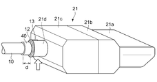
- FIG. 4 is a perspective view showing a state of a coupling portion between the cable body and the connector in the signal cable according to the embodiment of the present invention.
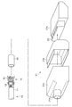
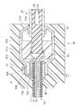
- FIG. 6 is an exploded perspective view showing a state of a coupling portion between the cable body and the connector in the signal cable according to the embodiment of the present invention. It is sectional drawing of the coupling part of the cable main body and connector in the signal cable which concerns on embodiment of this invention. It is sectional drawing of the coupling part of the cable main body and connector in the signal cable which concerns on the modification of this invention.
- FIG. 1 is a diagram showing an appearance of a signal cable 1 according to an embodiment of the present invention.
- FIG. 2 is a perspective view schematically showing a state where the cable body 10 of the signal cable 1 and the connector 20 are coupled to each other, and shows a state in which a cover 24 described later is not attached.
- FIG. 3 is an exploded perspective view showing a state before the cable body 10 of the signal cable 1 is connected to the connector 20.
- FIG. 4 is a schematic cross-sectional view showing a state in which the coupling portion between the cable body 10 and the connector 20 is cut along the cable extending direction.
- the signal cable 1 is attached to a linear cable body 10, a connector 20 attached to one end of the cable body 10, and an end portion of the cable body 10 opposite to the connector 20 side.
- the connector 30 and the supporting body 40 arranged at the connecting portion of the cable body 10 and the connector 20.
- the signal cable 1 is an HDMI cable
- the connector 30 attached to the opposite end may have the same structure as the connector 20. ..
- the connector 30 may have a structure different from that of the connector 20.
- the signal cable 1 connects two electronic devices, and these electronic devices are used for transmitting and receiving signals to and from each other.
- the electronic device to which the connector 20 is connected is referred to as a first electronic device E1
- the electronic device to which the connector 30 is connected is referred to as a second electronic device E2.
- the cable body 10 is configured to include a covering portion 11, a braided wire 12, a drain wire 13, and a plurality of signal wires 14. Specifically, the braided wire 12, the drain wire 13, and the plurality of signal wires 14 pass through the inside of the cable body 10, and the outside thereof is covered with the covering portion 11 of the insulator. That is, the covering portion 11 constitutes the outer surface of the cable body 10.
- the inside of the covering portion 11 may include a member other than those described here, such as an aluminum foil.
- the braided wire 12 is formed by braiding a plurality of thin thread-shaped conductive wires in a mesh shape.
- the braided wire 12 is formed in a tubular shape as a whole and is arranged immediately inside the covering portion 11.
- the material of the conductive wire forming the braided wire 12 may be various materials such as copper and an alloy of aluminum and magnesium.
- the drain wire 13 and the plurality of signal wires 14 all pass inside the braided wire 12.
- the drain wire 13 is a single conductive wire made of a conductive material such as a copper alloy.
- Each of the plurality of signal lines 14 is configured by a conductive core wire passing through the center and a coating of an insulator covering the periphery thereof, and the conductive core wire is electrically connected to the connection terminal 22 included in the connector 20. ing.
- the first electronic device E1 and the second electronic device E2 transmit and receive signals via the plurality of signal lines 14.
- the braided wire 12 and the drain wire 13 are in contact with and electrically connected to the shell 21 of the connector 20 described later. Thereby, when the connector 20 is connected to the first electronic device E1, the braided wire 12 and the drain wire 13 are electrically connected to the frame ground of the first electronic device E1. Further, the braided wire 12 and the drain wire 13 extend from the end of the cable body 10 on the connector 20 side to the end on the opposite side, and are electrically connected to the shell of the connector 30 on the end on the opposite side. .. In particular, by electrically connecting the drain wire 13 having a relatively low impedance to the connectors at both ends of the signal cable 1, the ground can be shared between the two electronic devices connected via the signal cable 1. ..
- the wiring electrically connected to the shell 21 of the connector 20 is referred to as a ground connection wire.
- both the braided wire 12 and the drain wire 13 function as ground connection wires.
- the connector 20 is configured to include a shell 21, a plurality of connection terminals 22, a housing 23, and a cover 24.
- the connector 20 is a plug connector, and is connected to the first electronic device E1 by being inserted into the receptacle connector included in the first electronic device E1.
- the shell 21 includes an insertion portion 21a that is inserted into the connector of the first electronic device E1 and is connected to the frame ground when the connector 20 is connected to the first electronic device E1, a front portion 21b carrying the insertion portion 21a, And a rear portion 21c provided with a coupling portion 21d that is coupled to the cable body 10, and is composed of three members. All of these three members are formed in a substantially cylindrical shape by using a material having conductivity.
- the insertion portion 21a is inserted into an opening provided on the front end side of the connector 20 of the front portion 21b (the side connected to the first electronic device E1).
- the opening of the front portion 21b on the center side of the cable (the side opposite to the side connected to the first electronic device E1) is fitted into the opening of the rear portion 21c on the tip side of the connector 20.
- the shell 21 as a whole has a cylindrical shape whose side surfaces are continuously formed.
- the shell 21 has openings at the connector tip side and the cable center side, but the intermediate portion other than the opening at the connector tip side and the coupling portion 21d Has no opening formed therein.
- the shell 21 functions as a shield case that shields the space inside the shell 21 including the portion where the signal line 14 is connected to the housing 23.
- the opening of the insertion portion 21a on the front end side of the connector is closed by a housing 23 described later. Further, the coupling portion 21d on the center side of the cable shields unnecessary electromagnetic radiation generated from the inside of the shell 21 by crimping the braided wire 12 as described later.
- a resin-made housing 23 is arranged in the insertion portion 21a, and a plurality of connection terminals 22 are accommodated in the housing 23.
- Each connection terminal 22 is electrically connected to the corresponding signal line 14 by soldering or the like, and is arranged in the connector of the first electronic device E1 in a state where the connector 20 is connected to the first electronic device E1. Is electrically connected to the connection terminal.
- FIG. 4 for simplification, only the two signal lines 14 connected to the two connection terminals 22 arranged above and below are shown.
- a resin 21e is filled in the rear portion 21c. As a result, the periphery of the portion of the housing 23 on the cable center side including the connection portion of the signal line 14 is protected by the resin 21e.
- a coupling portion 21d that is coupled to the cable body 10 is provided on the center of the rear portion 21c of the cable.
- the coupling portion 21d has a tubular shape that is substantially the same as the cable body 10 in a cross-sectional view, and the inner diameter thereof is larger than the outer diameter of the support body 40 described later.
- the cover 24 is a member that covers the portion of the shell 21 excluding the insertion portion 21a (that is, the portion on the cable body 10 side including the coupling portion 21d).
- the cover 24 is made of an insulating material such as resin.
- the cover 24 may be formed by fixing the shell 21 to the cable body 10 by a method described below and then filling the periphery thereof with resin.
- the support 40 is a member having a tubular shape, and is made of a conductive material such as iron.
- the support 40 may be formed using, for example, a steel plate. Further, it may be formed of a member obtained by plating another metal material on the surface of the base material. It is desirable that the support 40 has a higher rigidity than the covering portion 11 on the surface of the cable body 10. Further, it is desirable that the shell 21 has a rigidity equal to or higher than that of the coupling portion 21d of the shell 21.
- the shape of the support body 40 is not particularly limited as long as the support body 40 can surround the outer circumference of the cable body 10 in a cross-sectional view when it is fixed to the cable body 10.
- the support body 40 may have a shape in which one side surface is separated by a slit formed along the longitudinal direction. In this case, the support body 40 does not have an annular shape in cross section and has a C-shape.
- the inner diameter of the support body 40 is larger than the outer diameter of the cable body 10, and the end portion of the cable body 10 on the side connected to the connector 20 passes inside the support body 40.
- the tip of the braided wire 12 on the connector 20 side projects from the tip of the covering portion 11, and the projected portion is folded back to form a folded portion 12a.
- the folded portion 12a is arranged further outside the outer surface of the support body 40.
- the tip portion on the connector 20 side projects from the tip of the covering portion 11, and this projected portion is folded back to the outside of the support body 40 to form a folded portion 13a.
- the folded-back portion 13 a of the drain wire 13 is arranged further outside than the support 40 and the folded-back portion 12 a of the braided wire 12.
- the support body 40 may be fixed to the cable body 10 by crimping such as caulking.
- the support body 40 has an annular shape in cross section by performing the caulking process on the support body 40, and It will be in a state of surrounding the outer circumference.
- the rear portion 21c of the shell 21 is fixed to the cable body 10 by crimping such as caulking. Specifically, while the support body 40 and the cable body 10 pass through the inside of the joint 21d, the joint 21d is pressed from the outside. As a result, the rear portion 21c is fixed to the cable body 10.
- the location where the crimping process is performed is a position where the support 40, the folded-back portion 12a of the braided wire 12, and the folded-back portion 13a of the drain wire 13 are arranged outside the covering portion 11 of the cable body 10. That is, the drain wire 13, the braided wire 12, the covering portion 11, the support 40, the folded portion 12 a of the braided wire 12 and the drain wire 13 inside the cable body 10 are arranged along the radial direction from the center of the cable body 10 to the outside. With the folded-back portion 13a and the coupling portion 21d of the shell 21 overlapping in this order, pressure is applied from the outside of the coupling portion 21d toward the radial center of the cable body 10. As a result, the rear portion 21c is joined and fixed to the cable body 10.
- the block arrow in FIG. 2 indicates the position where the crimping process is performed.
- the folded-back portion 12a of the braided wire 12 is supported by the support body 40 during the crimping process and is attached to the inner surface of the coupling portion 21d. It will be pressed with strong pressure. As a result, the folded-back portion 12a is sandwiched between the support body 40 and the coupling portion 21d, and the braided wire 12 and the shell 21 are brought into close contact with each other as compared with the case where the support body 40 is not provided, and the electrical resistance between them is increased. Can be made smaller.
- the folded portion 13a of the drain wire 13 is also supported by the support body 40 and pressed against the inner surface of the coupling portion 21d to be sandwiched between the support body 40 and the coupling portion 21d.
- the drain wire 13 is also electrically connected to the shell 21 with a relatively low electric resistance.
- the length of the support body 40 along the extending direction is longer than the length of the joint portion 21d in the same direction. Furthermore, when crimping the coupling portion 21d, the position of the end portion of the support body 40 on the cable center side (the side opposite to the tip end side of the connector 20) is greater than the position of the end portion of the coupling portion 21d by the cable. It is carried out with the position adjusted to the center side. As a result, as shown in FIGS. 2 and 4, in the state where the shell 21 is fixed to the cable body 10, the end portion of the support body 40 on the cable center side protrudes from the coupling portion 21d by the width d. Has become.
- the support body 40 If the pressure-bonding process is performed while the support body 40 is deeper than the coupling portion 21d, the support body 40 enters too deeply and the position where the pressure-bonding process is performed deviates from the position where the support body 40 exists. There is a risk. In such a state, the ground connection line cannot be sandwiched between the support body 40 and the coupling portion 21d. Therefore, in the present embodiment, one end of the support body 40 is adjusted so as to be located closer to the center of the cable than the coupling portion 21d and the crimping process is performed, so that the support body 40 is surely present at the position for performing the crimping process.
- the support body 40 projects from the coupling portion 21d of the shell 21 in a state where the cover 24 is not present. Therefore, after the crimping process, the support body 40 is supported by visual inspection or another measuring method. It can be confirmed that the position of the body 40 is not displaced, which facilitates the management of the manufacturing process.
- the support body 40 does not necessarily have to have a portion protruding from the coupling portion 21d in a side view.
- the end portion of the support body 40 on the cable center side is an opening of the rear portion 21c on the cable center side. May have a portion exposed. Even with such a configuration, it is possible to visually confirm that the position of the support body 40 is not displaced after the crimping process.
- the tips of these ground connection wires may be soldered to the joint portion 21d of the shell 21.
- a soldering portion 13b is formed on the tip end side of the folded portion 13a of the drain wire 13 so as to further protrude from the portion sandwiched between the coupling portion 21d and the support body 40.
- the soldering portion 13b is arranged on the outer surface side of the coupling portion 21d with the tip of the folding portion 13a further folded back outward.
- the tip of the folded-back portion 12a of the braided wire 12 is also folded back outward to form a soldered portion 12b.
- soldering portions 12b and 13b are soldered to the joint portion 21d after the crimping process with the solder 41. Note that FIG. 2 shows a state before this soldering. Although both the braided wire 12 and the drain wire 13 are soldered here, all the ground connection wires may not be soldered, and for example, only the drain wire 13 may be soldered. ..
- the resin 21e is filled in the rear portion 21c in the state where the above-described crimping process and soldering are performed. Then, the front portion 21b is inserted from the front end side of the connector through the insertion portion 21a and fitted into the rear portion 21c. Thereby, the shell 21 is configured by connecting the insertion portion 21a, the front portion 21b, and the rear portion 21c. After that, the cover 24 is formed by filling a resin so as to cover the entire joint portion 21d and the portion of the support body 40 protruding from the joint portion 21d. In particular, the end portion of the cover 24 on the cable center side (the side opposite to the tip end side of the connector 20) is located closer to the cable center than the end portion of the support body 40 on the cable center side.
- the end surface of the support body 40 on the cable center side contacts the surface of the cover 24 facing the connector 20 side. Therefore, when the cable body 10 is pulled toward the center of the cable with respect to the cover 24, the end surface of the support body 40 is held by the cover 24, and the cable body 10 can be prevented from being pulled out.
- the manufacturing process of the signal cable 1 according to the present embodiment may be realized in an order different from the order described above.
- another example of the manufacturing process will be described.
- the insertion portion 21a of the shell 21 is attached to the housing 23 that houses the connection terminal 22, and then the tip end portion of each signal line 14 is soldered to the contact point at the rear of the housing 23.
- the front 21b of the shell 21 is fitted into the insertion portion 21a, and the resin 21e is first filled around the soldering portion.
- the support 40 is positioned.
- the support 40 may be fixed to the cable body 10 by pressure bonding or the like.
- the tip ends of the braided wire 12 and the drain wire 13 are folded back to the outside of the support body 40 to form the folded-back portion 12a and the folded-back portion 13a.
- the rear portion 21c of the shell 21 is fitted to the front portion 21b, and the coupling portion 21d is arranged at a position overlapping the support body 40.
- the connecting portion 21d is pressed against the support body 40 and the cable body 10 by crimping such as caulking to fix the rear portion 21c to the cable body 10.
- each of the braided wire 12 and the drain wire 13 can be electrically connected to the shell 21.
- the soldering portion 13b of the drain wire 13 and the soldering portion 12b of the braided wire 12 may be soldered to the joint portion 21d, if necessary.
- the cover 24 is formed by filling a resin so as to cover the entire joint portion 21d and the portion of the support body 40 protruding from the joint portion 21d.
- the signal cable 1 according to this embodiment can also be manufactured by the above steps.
- the signal cable 1 according to this embodiment is not limited to the example described above, and may be manufactured by another procedure.
- the support body 40 is arranged and the ground connection line in the cable body 10 is sandwiched between the support body 40 and the coupling portion 21d of the shell 21.
- the ground connection line can be surely electrically connected to the shell 21.
- unnecessary electromagnetic radiation generated from the connecting portion between the cable body 10 and the connector 20 can be suppressed.
- the embodiment of the present invention is not limited to the above description.
- the signal cable 1 is the HDMI cable in the above description
- the signal cable 1 is not limited to this and may be various cables.
- the present invention when the present invention is applied to a cable such as a USB cable that transmits and receives signals with a relatively high clock, it is possible to effectively suppress unnecessary electromagnetic radiation caused by such signal transmission and reception.
- the shapes and positional relationships of the cable body 10, the connector 20, and the support body 40 in the above description are all examples, and may have shapes and positional relationships different from those shown in the drawings without departing from the spirit of the present invention. You may.
- the tip portion of the ground connection line is once folded back to the cable center side and arranged on the outer surface side of the support body 40, and then the tip portion is folded back to the tip end side of the connector 20 and then the outer surface of the coupling portion 21d.
- the soldering portion arranged on the side and arranged on the outer surface side of the joint portion 21 is soldered to the joint portion 21d.
- FIG. 5 is a view showing a state of the ground connection line in a state where soldering is performed in this case, and a cross section along a cable extending direction of a connecting portion between the connector 20 and the cable body 10 as in FIG. Is shown.
- the width d2 of the portion where the support 40 projects from the coupling portion 21d toward the cable center side is larger than the width d of FIG.
- the folded-back portion 12a of the braided wire 12 and the folded-back portion 13a of the drain wire 13 are not further folded, unlike FIG. Have parts.
- the tip portions of the braided wire 12 and the drain wire 13 that protrude with respect to the ends of the coupling portion 21d function as soldering portions 12b and 13b. That is, soldering is performed from the outer surface of the coupling portion 21d to the outer surface of the support body 40, and the solder 41 is formed so as to cover the soldering portions 12b and 13b.
- the tip portions of the braided wire 12 and the drain wire 13 are electrically connected to the shell 21 via the solder 41.
- the braided wire 12 does not have a portion protruding from the end of the coupling portion 21d on the cable center side, and only the soldering portion 13b at the tip of the drain wire 13 is soldered to the shell 21. It may be done.
- the impedance between the connector 20 and the connector 30 may be sufficiently reduced only by the braided wire 12.
- the ground connecting line may be only the braided line 12, and the drain line 13 may be omitted.
- the ground connection line may be only the drain line 13, and the braided line 12 may not be connected to the shell 21.
- the ground connection line may include a conductor wire having a different shape other than the braided wire 12 and the drain wire 13.
Landscapes
- Details Of Connecting Devices For Male And Female Coupling (AREA)
Abstract
電子機器が備える接続端子と接続される接続端子(22)を収容し、電子機器に接続された状態において電子機器のフレームグラウンドに電気的に接続されるシェル(21)を備えるコネクタ(20)と、シェル(21)に電気的に接続されるグラウンド接続線を含むケーブル本体(10)と、筒状の形状を有し、ケーブル本体(10)の表面よりも高い剛性を有する支持体(40)と、を備え、ケーブル本体(10)のコネクタ側の先端部は支持体(40)の内側を通っており、グラウンド接続線のコネクタ側の先端部は、折り返されて支持体(40)の外側に配置される折り返し部を備え、シェル(21)は、当該折り返し部を支持体(40)との間で挟んだ状態でケーブル本体(10)に固定されている信号ケーブルである。
Description
本発明は、電子機器に接続するためのコネクタを備える信号ケーブル、及びその製造方法に関する。
一般的に、HDMI(登録商標)など各種の規格で信号を送受信する信号ケーブルは、電子機器に接続するためのコネクタを備えている。信号ケーブルのケーブル本体にコネクタを取り付ける際には、信号ケーブル内を通っている導線のうち、編組線などの一部の導線が、コネクタの接続端子を収容する外殻(シェル)と電気的に接続されるよう加工される。これにより、信号ケーブルを電子機器に接続した際に、シェルと接続された導線を電子機器のフレームグラウンドと電気的に接続することができる。
ケーブル本体の配線の自由度を高めるために、内部の導線や導線を覆う被覆部は可撓性が高い材料で形成されている。そのため、ケーブル本体にコネクタを取り付ける際に、編組線のような導線をコネクタの外殻に確実に電気的に接続するよう加工するのは容易でない。特に信号ケーブルが高クロックで信号の送受信を行う場合、導線とコネクタの外殻との間の接触が十分でないと、不要電磁放射等が生じる原因となる。
本発明は上記実情を考慮してなされたものであって、その目的の一つは、電子機器のフレームグラウンドに接続すべき導線が確実にコネクタの外殻に電気的に接続された信号ケーブル、及びその製造方法を提供することにある。
本発明に係る信号ケーブルは、電子機器に接続されるコネクタであって、前記電子機器が備える接続端子と接続される接続端子を収容し、前記電子機器に接続された状態において前記電子機器のフレームグラウンドに電気的に接続される外殻を備えるコネクタと、前記外殻に電気的に接続されるグラウンド接続線を含むケーブル本体と、筒状の形状を有し、前記ケーブル本体の表面よりも高い剛性を有する支持体と、を備え、前記ケーブル本体の前記コネクタ側の先端部は前記支持体の内側を通っており、前記グラウンド接続線の前記コネクタ側の先端部は、折り返されて前記支持体の外側に配置される折り返し部を備え、前記外殻は、前記折り返し部を前記支持体との間で挟んだ状態で前記ケーブル本体に固定されていることを特徴とする。
本発明に係る信号ケーブルの製造方法は、電子機器に接続されるコネクタであって、前記電子機器が備える接続端子と接続される接続端子を収容し、前記電子機器に接続された状態において前記電子機器のフレームグラウンドに電気的に接続される外殻を備えるコネクタと、前記外殻に電気的に接続されるグラウンド接続線を含むケーブル本体と、筒状の形状を有し、前記ケーブル本体の表面よりも高い剛性を有する支持体と、を備える信号ケーブルの製造方法であって、前記ケーブル本体の前記コネクタ側の先端部を前記支持体の内側に通した状態において、前記グラウンド接続線の先端部を前記支持体の外側に折り返して折り返し部を形成する工程と、前記外殻の前記コネクタ先端側と反対側に形成された結合部を、前記折り返し部を前記支持体と前記結合部の間で挟んだ状態で圧着することによって、前記外殻を前記ケーブル本体に固定する工程と、を含むことを特徴とする。
以下、本発明の実施の形態について、図面に基づき詳細に説明する。
図1は、本発明の実施形態に係る信号ケーブル1の外観を示す図である。図2は、信号ケーブル1のケーブル本体10とコネクタ20との結合部分の様子を模式的に示す斜視図であって、後述するカバー24が取り付けられていない状態の様子を示している。図3は、信号ケーブル1のケーブル本体10をコネクタ20と結合する前の状態を示す分解斜視図である。また、図4はケーブル本体10とコネクタ20の結合部分をケーブル延伸方向に沿って切断した様子を示す模式的な断面図である。
これらの図に示されるように、信号ケーブル1は、線状のケーブル本体10と、ケーブル本体10の一端に取り付けられたコネクタ20と、ケーブル本体10のコネクタ20側と逆側の端部に取り付けられたコネクタ30と、ケーブル本体10とコネクタ20との結合部分に配置される支持体40と、を含んで構成されている。
以下では具体例として、信号ケーブル1がHDMIケーブルである場合について説明する。また、以下ではケーブル本体10の一方の端部に取り付けられたコネクタ20の構造について説明するが、逆側の端部に取り付けられたコネクタ30もコネクタ20と同様の構造を有するものであってよい。あるいは、コネクタ30はコネクタ20とは異なる構造を有するものであってもよい。
信号ケーブル1は、2台の電子機器を接続し、これらの電子機器が相互に信号を送受信するために用いられる。以下では、コネクタ20が接続される電子機器を第1電子機器E1と表記し、コネクタ30が接続される電子機器を第2電子機器E2と表記する。
ケーブル本体10は、被覆部11と、編組線12と、ドレイン線13と、複数の信号線14と、を含んで構成されている。具体的に、ケーブル本体10の内側には編組線12、ドレイン線13、及び複数の信号線14が通っており、これらの外側を絶縁体の被覆部11が覆っている。すなわち、被覆部11がケーブル本体10の外面を構成している。なお、被覆部11の内側には、例えばアルミニウム箔など、ここで説明したもの以外の部材が含まれてもよい。
編組線12は、複数本の細い糸状の導電線を網目状に編んで構成されている。編組線12は全体として筒状に形成されており、被覆部11のすぐ内側に配置されている。編組線12を構成する導電線の材料は、例えば銅や、アルミニウムとマグネシウムの合金など、各種のものであってよい。
ドレイン線13、及び複数の信号線14は、いずれも編組線12の内側を通っている。ドレイン線13は、例えば銅合金などの導電材料によって構成された1本の導電線である。複数の信号線14は、それぞれ中心を通る導電性の芯線とその周囲を覆う絶縁体の被覆によって構成されており、この導電性の芯線が、コネクタ20が備える接続端子22に電気的に接続されている。第1電子機器E1と第2電子機器E2とは、これら複数の信号線14を介して信号の送受信を行う。
本実施形態では、編組線12、及びドレイン線13が、後述するコネクタ20のシェル21に接触し、電気的に接続されている。これにより、コネクタ20が第1電子機器E1に接続された際に、編組線12及びドレイン線13が第1電子機器E1のフレームグラウンドに電気的に接続されることになる。さらに編組線12及びドレイン線13は、ケーブル本体10のコネクタ20側の端部から逆側の端部まで延伸しており、逆側の端部ではコネクタ30のシェルと電気的に接続されている。特に比較的インピーダンスの低いドレイン線13を信号ケーブル1両端のコネクタに電気的に接続することによって、信号ケーブル1を介して接続される2台の電子機器の間でグラウンドを共通化することができる。なお、以下ではケーブル本体10内を通っている配線のうち、コネクタ20のシェル21に電気的に接続される配線を、グラウンド接続線という。本実施形態では、編組線12とドレイン線13の双方がグラウンド接続線として機能する。
コネクタ20は、シェル21と、複数の接続端子22と、ハウジング23と、カバー24と、を含んで構成されている。本実施形態においてコネクタ20は、プラグコネクタであって、第1電子機器E1が備えるレセプタクルコネクタ内に挿入されることによって第1電子機器E1と接続されることとする。
シェル21は、コネクタ20を第1電子機器E1に接続する際に第1電子機器E1のコネクタ内に挿入されてそのフレームグラウンドと接続される挿入部21a、挿入部21aを担持するフロント部21b、及びケーブル本体10に結合する結合部21dを備えるリア部21cの3個の部材から構成されている。これら3個の部材は、いずれも導電性を有する材料によって概略筒状に形成されている。挿入部21aは、フロント部21bのコネクタ20先端側(第1電子機器E1に接続される側)に設けられた開口に挿入されている。また、フロント部21bのケーブル中央側(第1電子機器E1に接続される側と逆側)の開口は、リア部21cのコネクタ20先端側の開口に嵌合している。これによりシェル21は、全体として側面が連続的に形成された筒状の形状を有することになる。なお、3個の部材が組み合わされた状態においてシェル21は、コネクタ先端側、及びケーブル中央側に開口を有しているが、コネクタ先端側の開口と結合部21dを除いたそれ以外の中間部分には、開口が形成されていない。これによりシェル21は、信号線14がハウジング23に接続される箇所を含むシェル21内部の空間を遮蔽するシールドケースとして機能する。なお、挿入部21aのコネクタ先端側の開口は後述するハウジング23によって塞がれている。また、ケーブル中央側の結合部21dは、後述するように編組線12と圧着することによって、シェル21内部から発生する不要電磁放射を遮蔽している。
挿入部21a内には、樹脂製のハウジング23が配置されており、このハウジング23内に複数の接続端子22が収容されている。各接続端子22は、対応する信号線14とはんだ付けなどによって電気的に接続されており、コネクタ20が第1電子機器E1に接続された状態において、第1電子機器E1のコネクタ内に配置された接続端子と電気的に接続される。なお、図4においては簡略化のために、上下に配置された2個の接続端子22と接続される2本の信号線14のみが示されている。図4に示されるように、リア部21c内には樹脂21eが充填されている。これにより、信号線14の接続箇所を含むハウジング23のケーブル中央側の部分の周囲が、樹脂21eによって保護されている。
リア部21cのケーブル中央側には、ケーブル本体10と結合する結合部21dが設けられている。結合部21dは、断面視においてケーブル本体10と略同形の筒状の形状を有しており、その内径は、後述する支持体40の外径よりも大きくなっている。
カバー24は、シェル21の挿入部21aを除いた部分(すなわち、結合部21dを含むケーブル本体10側の部分)を覆う部材である。カバー24は、樹脂等の絶縁材料によって形成されている。例えばカバー24は、後述する方法によってシェル21をケーブル本体10に固定した後に、その周囲に樹脂を充填することによって形成されてよい。
支持体40は、筒状の形状を有する部材であって、例えば鉄などの導電材料によって形成されている。具体的に、支持体40は例えば鋼板を用いて形成されてよい。また、母材の表面に対して別の金属材料をメッキしてなる部材で形成されてもよい。支持体40は、ケーブル本体10の表面の被覆部11よりも高い剛性を有することが望ましい。また、シェル21の結合部21dと同じか、それ以上の剛性を有することが望ましい。なお、支持体40はケーブル本体10に固定された際に断面視においてケーブル本体10の外周を取り囲むことができれば、その形状は特に限定されない。例えば支持体40は、長手方向に沿って形成されたスリットによって側面の一箇所が切り離された形状を有してもよい。この場合、支持体40は断面視において環状にならず、C字形状を有することになる。
支持体40の内径は、ケーブル本体10の外径よりも大きくなっており、この支持体40の内側に、ケーブル本体10のコネクタ20に接続される側の端部が通っている。編組線12のコネクタ20側の先端は、被覆部11の先端より突出しており、この突出した部分が外側に折り返されて折り返し部12aを形成している。折り返し部12aは、支持体40の外面のさらに外側に配置されている。また、ドレイン線13についても、コネクタ20側の先端部が被覆部11の先端より突出し、この突出した部分が支持体40の外側に折り返されて折り返し部13aを形成している。ドレイン線13の折り返し部13aは、支持体40、及び編組線12の折り返し部12aよりさらに外側に配置されている。
ここで、信号ケーブル1を製造する工程の一部であるシェル21の組み立て工程、及びシェル21とケーブル本体10とを結合する工程の一例について、説明する。まずケーブル本体10の先端部を支持体40、及びリア部21cに通した状態で、各信号線14の先端部を、ハウジング23後方に露出している接点にはんだ付けする。この接点は、ハウジング23内部でコネクタ20先端側の接続端子22と連結されている。この状態において、編組線12及びドレイン線13それぞれの先端部を支持体40の外側に折り返して、折り返し部12a及び折り返し部13aを形成する。なお、ケーブル本体10を支持体40に通した段階で、カシメ加工等の圧着加工によって支持体40をケーブル本体10に固定してもよい。なお、前述したように支持体40の側面にスリットが形成されている場合、支持体40に対してこのようなカシメ加工を行うことによって、支持体40が断面視環状になり、ケーブル本体10の外周を取り囲んだ状態となる。
その後、カシメ加工等の圧着加工によってシェル21のリア部21cをケーブル本体10に対して固定する。具体的には、支持体40及びケーブル本体10が結合部21d内を通っている状態において、結合部21dを外側から加圧する。これにより、リア部21cがケーブル本体10に対して固定される。
圧着加工が施される箇所は、ケーブル本体10の被覆部11の外側に支持体40、編組線12の折り返し部12a、及びドレイン線13の折り返し部13aが配置されている位置である。すなわち、ケーブル本体10の中心から外側に向かう径方向に沿って、ケーブル本体10内部のドレイン線13、編組線12、被覆部11、支持体40、編組線12の折り返し部12a、ドレイン線13の折り返し部13a、及びシェル21の結合部21dがこの順に重なっている状態で、結合部21dの外側からケーブル本体10の径方向の中心に向かって圧力を加える。これにより、リア部21cがケーブル本体10に結合し、固定される。なお、図2のブロック矢印は圧着加工が行われる位置を示している。
前述したように、支持体40は被覆部11よりも高い剛性を有しているため、編組線12の折り返し部12aは、圧着加工の際に支持体40に支持されて結合部21dの内面に強い圧力で押し当てられることになる。これにより、折り返し部12aが支持体40と結合部21dとに挟持された状態となり、支持体40がない場合と比較して、編組線12とシェル21とを密着させ、両者の間の電気抵抗を小さくすることができる。同様に、ドレイン線13の折り返し部13aについても、支持体40に支持されて結合部21dの内面に押し当てられ、支持体40と結合部21dとに挟持された状態となる。これにより、ドレイン線13も比較的少ない電気抵抗でシェル21と電気的に接続される。
ここで、支持体40の延伸方向に沿った長さは、結合部21dの同じ向きの長さよりも長くなっている。さらに、結合部21dの圧着加工が行われる際には、支持体40のケーブル中央側(コネクタ20の先端側と逆側)の端部の位置が、結合部21dの端部の位置よりもケーブル中央側に位置するよう調整した状態で行われる。これにより、図2及び図4に示されるように、シェル21がケーブル本体10に固定された状態において、支持体40のケーブル中央側の端部は結合部21dよりも幅dだけ突出した状態になっている。仮に支持体40が結合部21dよりも奥に入った状態で圧着加工を行うこととすると、支持体40が奥に入り込みすぎて圧着加工を行う位置が支持体40の存在する位置とずれてしまうおそれがある。このような状態になると、グラウンド接続線を支持体40と結合部21dで挟持することができなくなる。そこで本実施形態では、支持体40の一端が結合部21dよりもケーブル中央寄りの位置になるよう調整して圧着加工を行うことによって、圧着加工を行う位置に確実に支持体40が存在するようにすることができる。また、このような位置で圧着加工を行うことにより、カバー24が存在しない状態であれば支持体40がシェル21の結合部21dから突出するので、圧着加工後に、目視やその他の測定方法で支持体40の位置がずれていないことを確認することができ、製造工程の管理が容易になる。
なお、支持体40の位置ずれが生じていないことを確認することができれば、必ずしも側面視において支持体40が結合部21dに対して突出する部分を有しておらずともよい。例えば支持体40及び結合部21dそれぞれのケーブル中央側の端部が互いに面一になるように配置するなどして、支持体40のケーブル中央側の端部がリア部21cのケーブル中央側の開口において露出する部分を有するようにしてもよい。このような構成でも、支持体40の位置がずれていないことを圧着加工後に目視で確認できる。
さらに編組線12及びドレイン線13を少ない電気抵抗でシェル21と電気的に接続するために、これらのグラウンド接続線の先端部をシェル21の結合部21dにはんだ付けしてもよい。図4の例では、ドレイン線13の折り返し部13aの先端側には、結合部21dと支持体40とに挟まれている部分からさらに突出してなるはんだ付け部13bが形成されている。このはんだ付け部13bは、折り返し部13aの先端がさらに外側に折り返されて、結合部21dの外面側に配置されている。同様に、編組線12の折り返し部12aの先端もさらに外側に折り返されて、はんだ付け部12bを形成している。これらのはんだ付け部12b及び13bが、はんだ41によって圧着加工後の結合部21dにはんだ付けされている。なお、図2ではこのはんだ付けがされる前の状態が示されている。また、ここでは編組線12及びドレイン線13の双方がはんだ付けされることとしたが、グラウンド接続線の全てがはんだ付けされずともよく、例えばドレイン線13だけがはんだ付けされることとしてもよい。
以上説明した圧着加工及びはんだ付けを行った状態において、リア部21c内に樹脂21eを充填する。そして、コネクタ先端側から挿入部21aを通してフロント部21bを差し込み、リア部21cと嵌合させる。これにより、挿入部21a、フロント部21b、及びリア部21cが連結されてシェル21が構成される。さらにその後、結合部21dの全体、及び支持体40の結合部21dから突出する部分を覆うように樹脂を充填することによって、カバー24を形成する。特にカバー24のケーブル中央側(コネクタ20の先端側と逆側)の端部は、支持体40のケーブル中央側の端部よりもケーブル中央寄りの位置になっている。これにより、支持体40のケーブル中央側の端面が、カバー24のコネクタ20側に向けられた面に当接する。そのため、ケーブル本体10をカバー24に対してケーブル中央方向に向けて引っ張った場合に、支持体40の端面がカバー24に抑えられ、ケーブル本体10が引き抜かれてしまわないようにすることができる。
なお、本実施形態に係る信号ケーブル1の製造工程は、以上説明した順序と異なる順序で実現されてもよい。以下、製造工程の別の例について説明する。まずこれまで説明した例と同様に、ケーブル本体10の先端部を支持体40、及びリア部21cに通した状態で、各信号線14の先端部の導線を露出させる加工を行う。そして、接続端子22を収容するハウジング23にシェル21の挿入部21aを取り付けてから、各信号線14の先端部をハウジング23後方の接点にはんだ付けする。それから、前述の例と異なり、シェル21のフロント21bを挿入部21aに嵌合し、先にはんだ付け箇所の周囲に樹脂21eを充填する。
その後、支持体40の位置決めをする。このとき前述したように、圧着加工等によって支持体40をケーブル本体10に対して固定してもよい。そして、前述した例と同様に、編組線12及びドレイン線13それぞれの先端部を支持体40の外側に折り返して、折り返し部12a及び折り返し部13aを形成する。その後、シェル21のリア部21cをフロント部21bに嵌合して結合部21dを支持体40と重なる位置に配置する。そして、カシメ加工等の圧着加工によって、結合部21dを支持体40及びケーブル本体10に押しつけてリア部21cをケーブル本体10に対して固定する。これにより、編組線12及びドレイン線13のそれぞれをシェル21に電気的に接続させることができる。
その後、必要に応じてドレイン線13のはんだ付け部13b、及び編組線12のはんだ付け部12bを結合部21dにはんだ付けしてもよい。さらにその後、結合部21dの全体、及び支持体40の結合部21dから突出する部分を覆うように樹脂を充填することによって、カバー24を形成する。以上の工程によっても、本実施形態に係る信号ケーブル1を製造することができる。また、以上説明した例に限らず、本実施形態に係る信号ケーブル1はその他の手順で製造されることとしてもよい。
以上説明した本発明の実施の形態に係る信号ケーブル1によれば、支持体40を配置してこの支持体40とシェル21の結合部21dとでケーブル本体10内のグラウンド接続線を挟持することによって、グラウンド接続線を確実にシェル21と電気的に接続することができる。これにより、ケーブル本体10とコネクタ20との結合部分から発生する不要電磁放射を抑制することができる。
なお、本発明の実施の形態は、以上説明したものに限られない。例えば以上の説明では、信号ケーブル1はHDMIケーブルであることとしたが、これに限らず各種のケーブルであってよい。特に本発明をUSBケーブルなど比較的高クロックで信号の送受信を行うケーブルに適用した場合、このような信号の送受信に伴って生じる不要電磁放射を効果的に抑制することができる。
また、以上の説明におけるケーブル本体10、コネクタ20、及び支持体40の形状や位置関係はいずれも例示であって、本発明の趣旨を損なわない範囲で図示したものと異なる形状や位置関係を有してもよい。例えば以上の説明においては、グラウンド接続線の先端部を一度ケーブル中央側に折り返して支持体40の外面側に配置した後、さらにその先端部をコネクタ20先端側に再び折り返して結合部21dの外面側に配置し、この結合部21の外面側に配置したはんだ付け部を結合部21dに対してはんだ付けすることとした。しかしながらこれに限らず、結合部21dの外面側への折り返しを行わずにまっすぐ伸ばした状態でグラウンド接続線の先端部をはんだ付け部としてもよい。図5は、この場合においてはんだ付けが行われた状態のグラウンド接続線の様子を示す図であって、図4と同様にコネクタ20とケーブル本体10との結合部分のケーブル延伸方向に沿った断面の様子を示している。
図5の例では、支持体40が結合部21dよりケーブル中央側に突出した部分の幅d2が、図4の幅dと比較して大きくなっている。そして、編組線12の折り返し部12a、及びドレイン線13の折り返し部13aは、いずれも図4と異なりさらなる折り返しはされておらず、結合部21dのケーブル中央側の端部よりも突出して延伸する部分を有している。編組線12及びドレイン線13それぞれの、結合部21dの端部に対して突出した先端部分が、はんだ付け部12b及び13bとして機能する。すなわち、結合部21dの外面から支持体40の外面にまたがってはんだ付けがされ、はんだ付け部12b及び13bを覆うようにはんだ41が形成されている。これにより、編組線12及びドレイン線13の先端部分がはんだ41を介してシェル21に電気的に接続されている。なお、図4の場合と同様、編組線12は結合部21dのケーブル中央側の端部より突出した部分を有しないこととし、ドレイン線13先端のはんだ付け部13bだけがシェル21にはんだ付けされることとしてもよい。
また、編組線12を構成する材料の電気特性や断面積などによっては、編組線12だけでコネクタ20とコネクタ30との間のインピーダンスを十分下げることができる場合がある。このような場合、グラウンド接続線は編組線12だけでよく、ドレイン線13はなくともよい。この場合、編組線12だけが支持体40と結合部21dとに挟持されてシェル21に電気的に接続されることになる。逆に、グラウンド接続線はドレイン線13だけであってもよく、編組線12はシェル21に接続されないこととしてもよい。また、グラウンド接続線は、編組線12やドレイン線13以外の別の形状を有する導線を含んでもよい。
1 信号ケーブル、10 ケーブル本体、11 被覆部、12 編組線、13 ドレイン線、14 信号線、20 コネクタ、21 シェル、21a 挿入部、21b フロント部、21c リア部、21d 結合部、21e 樹脂、22 接続端子、23 ハウジング、24 カバー、30 コネクタ、40 支持体、41 はんだ。
Claims (10)
- 電子機器に接続されるコネクタであって、前記電子機器が備える接続端子と接続される接続端子を収容し、前記電子機器に接続された状態において前記電子機器のフレームグラウンドに電気的に接続される外殻を備えるコネクタと、
前記外殻に電気的に接続されるグラウンド接続線を含むケーブル本体と、
筒状の形状を有し、前記ケーブル本体の表面よりも高い剛性を有する支持体と、
を備え、
前記ケーブル本体の前記コネクタ側の先端部は前記支持体の内側を通っており、
前記グラウンド接続線の前記コネクタ側の先端部は、折り返されて前記支持体の外側に配置される折り返し部を備え、
前記外殻は、前記折り返し部を前記支持体との間で挟んだ状態で前記ケーブル本体に固定されている
ことを特徴とする信号ケーブル。 - 請求項1に記載の信号ケーブルにおいて、
前記支持体の前記コネクタ先端側と反対側の端部は、前記外殻の前記コネクタ先端側と反対側の端部よりも突出してなる部分を有する
ことを特徴とする信号ケーブル。 - 請求項1に記載の信号ケーブルにおいて、
前記支持体の前記コネクタ先端側と反対側の端部は、前記外殻の前記コネクタ先端側と反対側の開口において露出する部分を有する
ことを特徴とする信号ケーブル。 - 請求項1から3のいずれか一項に記載の信号ケーブルにおいて、
前記折り返し部は、その先端側において前記外殻と前記支持体とに挟まれていないはんだ付け部を備え、当該はんだ付け部が前記外殻にはんだ付けされている
ことを特徴とする信号ケーブル。 - 請求項4に記載の信号ケーブルにおいて、
前記はんだ付け部は、前記折り返し部の先端がさらに外側に折り返されて、前記外殻の外面にはんだ付けされている
ことを特徴とする信号ケーブル。 - 請求項4に記載の信号ケーブルにおいて、
前記はんだ付け部は、前記支持体のうち前記外殻と重ならない部分の外面に配置され、前記外殻の外面から前記支持体の外面にまたがって形成されたはんだによって前記外殻と接続されている
ことを特徴とする信号ケーブル。 - 請求項1から6のいずれか一項に記載の信号ケーブルにおいて、
前記外殻は、複数の部材が連結されて構成されており、当該複数の部材は、互いに連結された状態において筒状の形状を有し、前記コネクタ先端側、及び前記ケーブル本体に固定されている部分を除いた中間部分に開口が形成されていない
ことを特徴とする信号ケーブル。 - 請求項1から7のいずれか一項に記載の信号ケーブルにおいて、
前記グラウンド接続線は、複数の導電線を編んで形成された編組線を含む
ことを特徴とする信号ケーブル。 - 請求項1から8のいずれか一項に記載の信号ケーブルにおいて、
前記グラウンド接続線は、1本の導電線によって構成されるドレイン線を含む
ことを特徴とする信号ケーブル。 - 電子機器に接続されるコネクタであって、前記電子機器が備える接続端子と接続される接続端子を収容し、前記電子機器に接続された状態において前記電子機器のフレームグラウンドに電気的に接続される外殻を備えるコネクタと、
前記外殻に電気的に接続されるグラウンド接続線を含むケーブル本体と、
筒状の形状を有し、前記ケーブル本体の表面よりも高い剛性を有する支持体と、
を備える信号ケーブルの製造方法であって、
前記ケーブル本体の前記コネクタ側の先端部を前記支持体の内側に通した状態において、前記グラウンド接続線の先端部を前記支持体の外側に折り返して折り返し部を形成する工程と、
前記外殻の前記コネクタ先端側と反対側に形成された結合部を、前記折り返し部を前記支持体と前記結合部の間で挟んだ状態で圧着することによって、前記外殻を前記ケーブル本体に固定する工程と、
を含むことを特徴とする信号ケーブルの製造方法。
Priority Applications (3)
| Application Number | Priority Date | Filing Date | Title |
|---|---|---|---|
| JP2020568153A JP7191127B2 (ja) | 2019-01-21 | 2020-01-21 | 信号ケーブル |
| US17/421,690 US11978984B2 (en) | 2019-01-21 | 2020-01-21 | Signal cable connection device having a folded wire |
| CN202080009195.XA CN113302805B (zh) | 2019-01-21 | 2020-01-21 | 信号电缆 |
Applications Claiming Priority (2)
| Application Number | Priority Date | Filing Date | Title |
|---|---|---|---|
| JP2019007945 | 2019-01-21 | ||
| JP2019-007945 | 2019-01-21 |
Publications (1)
| Publication Number | Publication Date |
|---|---|
| WO2020153347A1 true WO2020153347A1 (ja) | 2020-07-30 |
Family
ID=71736792
Family Applications (1)
| Application Number | Title | Priority Date | Filing Date |
|---|---|---|---|
| PCT/JP2020/001909 Ceased WO2020153347A1 (ja) | 2019-01-21 | 2020-01-21 | 信号ケーブル |
Country Status (4)
| Country | Link |
|---|---|
| US (1) | US11978984B2 (ja) |
| JP (1) | JP7191127B2 (ja) |
| CN (1) | CN113302805B (ja) |
| WO (1) | WO2020153347A1 (ja) |
Cited By (2)
| Publication number | Priority date | Publication date | Assignee | Title |
|---|---|---|---|---|
| CN112071484A (zh) * | 2020-09-25 | 2020-12-11 | 广州互媒盈动文化传媒科技有限公司 | 一种多媒体信息识别、存取系统 |
| JP2024533285A (ja) * | 2021-10-01 | 2024-09-12 | 長春捷翼汽車科技股▲フン▼有限公司 | シールド付き接続機構、送電装置及び自動車 |
Families Citing this family (2)
| Publication number | Priority date | Publication date | Assignee | Title |
|---|---|---|---|---|
| CN110729598A (zh) * | 2019-10-21 | 2020-01-24 | 西门子股份公司 | 信号电缆连接器及电机组件 |
| JP7371505B2 (ja) * | 2020-01-20 | 2023-10-31 | 住友電装株式会社 | ワイヤハーネス |
Citations (5)
| Publication number | Priority date | Publication date | Assignee | Title |
|---|---|---|---|---|
| JPS63133077U (ja) * | 1987-02-23 | 1988-08-31 | ||
| JPH10108346A (ja) * | 1996-10-01 | 1998-04-24 | Yokogawa Denshi Kiki Kk | ワイヤハーネスの端末構造 |
| US5820412A (en) * | 1997-03-18 | 1998-10-13 | The Whitaker Corporation | Connector shield with cable crimp support |
| JP2002270309A (ja) * | 2001-03-08 | 2002-09-20 | Auto Network Gijutsu Kenkyusho:Kk | シールドケーブルの端末処理構造 |
| JP2012048818A (ja) * | 2010-08-24 | 2012-03-08 | Auto Network Gijutsu Kenkyusho:Kk | 端子圧着方法 |
Family Cites Families (10)
| Publication number | Priority date | Publication date | Assignee | Title |
|---|---|---|---|---|
| GB1473676A (en) * | 1973-06-07 | 1977-05-18 | Bunker Ramo | Connector for terminating coaxial cable |
| FR2740914A1 (fr) * | 1995-11-02 | 1997-05-09 | Amp France | Connecteur pour cable blinde |
| US5725387A (en) * | 1996-03-01 | 1998-03-10 | Molex Incorporated | System for terminating the shield of a high speed cable |
| JP4316482B2 (ja) | 2004-12-03 | 2009-08-19 | 矢崎総業株式会社 | シールド電線のアース処理方法及びアース処理構造 |
| JP4611222B2 (ja) * | 2006-02-20 | 2011-01-12 | 矢崎総業株式会社 | シールド電線の接続構造 |
| JP2007294238A (ja) * | 2006-04-25 | 2007-11-08 | Yazaki Corp | 端子取付方法及び端子付き同軸ケーブル |
| CN201112598Y (zh) * | 2007-09-25 | 2008-09-10 | 许庆仁 | 一种改良的信号传输线 |
| JP2010153268A (ja) * | 2008-12-26 | 2010-07-08 | D D K Ltd | アース構造及び該アース構造を用いた電気コネクタ |
| JP5762219B2 (ja) * | 2011-08-31 | 2015-08-12 | 矢崎総業株式会社 | シールド電線の編組シールド層とドレイン線との接続方法、及び、接続構造 |
| JP6114672B2 (ja) * | 2013-09-27 | 2017-04-12 | ホシデン株式会社 | コネクタ |
-
2020
- 2020-01-21 JP JP2020568153A patent/JP7191127B2/ja active Active
- 2020-01-21 WO PCT/JP2020/001909 patent/WO2020153347A1/ja not_active Ceased
- 2020-01-21 US US17/421,690 patent/US11978984B2/en active Active
- 2020-01-21 CN CN202080009195.XA patent/CN113302805B/zh active Active
Patent Citations (5)
| Publication number | Priority date | Publication date | Assignee | Title |
|---|---|---|---|---|
| JPS63133077U (ja) * | 1987-02-23 | 1988-08-31 | ||
| JPH10108346A (ja) * | 1996-10-01 | 1998-04-24 | Yokogawa Denshi Kiki Kk | ワイヤハーネスの端末構造 |
| US5820412A (en) * | 1997-03-18 | 1998-10-13 | The Whitaker Corporation | Connector shield with cable crimp support |
| JP2002270309A (ja) * | 2001-03-08 | 2002-09-20 | Auto Network Gijutsu Kenkyusho:Kk | シールドケーブルの端末処理構造 |
| JP2012048818A (ja) * | 2010-08-24 | 2012-03-08 | Auto Network Gijutsu Kenkyusho:Kk | 端子圧着方法 |
Cited By (3)
| Publication number | Priority date | Publication date | Assignee | Title |
|---|---|---|---|---|
| CN112071484A (zh) * | 2020-09-25 | 2020-12-11 | 广州互媒盈动文化传媒科技有限公司 | 一种多媒体信息识别、存取系统 |
| JP2024533285A (ja) * | 2021-10-01 | 2024-09-12 | 長春捷翼汽車科技股▲フン▼有限公司 | シールド付き接続機構、送電装置及び自動車 |
| JP7748641B2 (ja) | 2021-10-01 | 2025-10-03 | 長春捷翼汽車科技股▲フン▼有限公司 | シールド付き接続機構、送電装置及び自動車 |
Also Published As
| Publication number | Publication date |
|---|---|
| JP7191127B2 (ja) | 2022-12-16 |
| US11978984B2 (en) | 2024-05-07 |
| JPWO2020153347A1 (ja) | 2021-11-11 |
| CN113302805B (zh) | 2023-09-01 |
| CN113302805A (zh) | 2021-08-24 |
| US20220094115A1 (en) | 2022-03-24 |
Similar Documents
| Publication | Publication Date | Title |
|---|---|---|
| JP4597256B2 (ja) | シールドコネクタ | |
| US9941608B2 (en) | Plug connector arrangement with compensation sleeve | |
| JP7191127B2 (ja) | 信号ケーブル | |
| US5823803A (en) | Electrical cable connector | |
| US8998641B2 (en) | Terminal structure of electrical cable, shielded connector and terminal treatment method of electrical cable | |
| US6146196A (en) | Mated coaxial contact system | |
| CN107919592B (zh) | 同轴电缆连接器以及同轴电缆连接方法 | |
| JP2020205255A (ja) | 超高周波信号伝送用同軸ケーブル雄コネクタ | |
| US20180375232A1 (en) | Cable connector assembly | |
| JP5823787B2 (ja) | 同軸ケーブルとシールド端子との接続構造およびその接続方法 | |
| EP0111162A1 (en) | Encapsulated, shielded, and grounded connector | |
| EP3232447B1 (en) | Cable assembly and cable assembly manufacturing method | |
| US6612870B1 (en) | Connector of the input/output type with grounded shielded cables and method of producing and of mounting such a connector | |
| CN107732480B (zh) | 线缆连接器组件 | |
| JP2023068262A (ja) | 端子及びコネクタ | |
| JP2008123913A (ja) | 内導体端子及び同軸コネクタ | |
| JP2009252356A (ja) | コネクタ端子 | |
| JP7364374B2 (ja) | シールドコネクタ | |
| JP5222169B2 (ja) | シールドコネクタ | |
| JP2019200898A (ja) | シールドコネクタ | |
| JP2017134967A (ja) | コネクタ付ケーブル | |
| JP2018006344A (ja) | 高周波電線側コネクタと同軸ケーブルとの接続方法及びそれに用いる内部端子 | |
| WO2021029198A1 (ja) | コネクタおよびコネクタ装置 | |
| JP3693973B2 (ja) | L字プラグとその組み立て方法 | |
| JP2020061342A (ja) | 端部構造および端部形成方法 |
Legal Events
| Date | Code | Title | Description |
|---|---|---|---|
| 121 | Ep: the epo has been informed by wipo that ep was designated in this application |
Ref document number: 20745636 Country of ref document: EP Kind code of ref document: A1 |
|
| ENP | Entry into the national phase |
Ref document number: 2020568153 Country of ref document: JP Kind code of ref document: A |
|
| NENP | Non-entry into the national phase |
Ref country code: DE |
|
| 122 | Ep: pct application non-entry in european phase |
Ref document number: 20745636 Country of ref document: EP Kind code of ref document: A1 |