WO2020149416A1 - 画像診断用カテーテル及び画像診断装置 - Google Patents
画像診断用カテーテル及び画像診断装置 Download PDFInfo
- Publication number
- WO2020149416A1 WO2020149416A1 PCT/JP2020/001609 JP2020001609W WO2020149416A1 WO 2020149416 A1 WO2020149416 A1 WO 2020149416A1 JP 2020001609 W JP2020001609 W JP 2020001609W WO 2020149416 A1 WO2020149416 A1 WO 2020149416A1
- Authority
- WO
- WIPO (PCT)
- Prior art keywords
- sheath
- support tube
- drive shaft
- tip
- communication port
- Prior art date
- Legal status (The legal status is an assumption and is not a legal conclusion. Google has not performed a legal analysis and makes no representation as to the accuracy of the status listed.)
- Ceased
Links
Images




Classifications
-
- A—HUMAN NECESSITIES
- A61—MEDICAL OR VETERINARY SCIENCE; HYGIENE
- A61B—DIAGNOSIS; SURGERY; IDENTIFICATION
- A61B5/00—Measuring for diagnostic purposes; Identification of persons
- A61B5/0059—Measuring for diagnostic purposes; Identification of persons using light, e.g. diagnosis by transillumination, diascopy, fluorescence
- A61B5/0082—Measuring for diagnostic purposes; Identification of persons using light, e.g. diagnosis by transillumination, diascopy, fluorescence adapted for particular medical purposes
- A61B5/0084—Measuring for diagnostic purposes; Identification of persons using light, e.g. diagnosis by transillumination, diascopy, fluorescence adapted for particular medical purposes for introduction into the body, e.g. by catheters
-
- A—HUMAN NECESSITIES
- A61—MEDICAL OR VETERINARY SCIENCE; HYGIENE
- A61B—DIAGNOSIS; SURGERY; IDENTIFICATION
- A61B1/00—Instruments for performing medical examinations of the interior of cavities or tubes of the body by visual or photographical inspection, e.g. endoscopes; Illuminating arrangements therefor
- A61B1/00147—Holding or positioning arrangements
- A61B1/0016—Holding or positioning arrangements using motor drive units
-
- A—HUMAN NECESSITIES
- A61—MEDICAL OR VETERINARY SCIENCE; HYGIENE
- A61B—DIAGNOSIS; SURGERY; IDENTIFICATION
- A61B1/00—Instruments for performing medical examinations of the interior of cavities or tubes of the body by visual or photographical inspection, e.g. endoscopes; Illuminating arrangements therefor
- A61B1/313—Instruments for performing medical examinations of the interior of cavities or tubes of the body by visual or photographical inspection, e.g. endoscopes; Illuminating arrangements therefor for introducing through surgical openings, e.g. laparoscopes
- A61B1/3137—Instruments for performing medical examinations of the interior of cavities or tubes of the body by visual or photographical inspection, e.g. endoscopes; Illuminating arrangements therefor for introducing through surgical openings, e.g. laparoscopes for examination of the interior of blood vessels
-
- A—HUMAN NECESSITIES
- A61—MEDICAL OR VETERINARY SCIENCE; HYGIENE
- A61B—DIAGNOSIS; SURGERY; IDENTIFICATION
- A61B5/00—Measuring for diagnostic purposes; Identification of persons
- A61B5/0059—Measuring for diagnostic purposes; Identification of persons using light, e.g. diagnosis by transillumination, diascopy, fluorescence
- A61B5/0062—Arrangements for scanning
-
- A—HUMAN NECESSITIES
- A61—MEDICAL OR VETERINARY SCIENCE; HYGIENE
- A61B—DIAGNOSIS; SURGERY; IDENTIFICATION
- A61B5/00—Measuring for diagnostic purposes; Identification of persons
- A61B5/68—Arrangements of detecting, measuring or recording means, e.g. sensors, in relation to patient
- A61B5/6846—Arrangements of detecting, measuring or recording means, e.g. sensors, in relation to patient specially adapted to be brought in contact with an internal body part, i.e. invasive
- A61B5/6847—Arrangements of detecting, measuring or recording means, e.g. sensors, in relation to patient specially adapted to be brought in contact with an internal body part, i.e. invasive mounted on an invasive device
- A61B5/6852—Catheters
- A61B5/6855—Catheters with a distal curved tip
-
- A—HUMAN NECESSITIES
- A61—MEDICAL OR VETERINARY SCIENCE; HYGIENE
- A61B—DIAGNOSIS; SURGERY; IDENTIFICATION
- A61B5/00—Measuring for diagnostic purposes; Identification of persons
- A61B5/68—Arrangements of detecting, measuring or recording means, e.g. sensors, in relation to patient
- A61B5/6846—Arrangements of detecting, measuring or recording means, e.g. sensors, in relation to patient specially adapted to be brought in contact with an internal body part, i.e. invasive
- A61B5/6867—Arrangements of detecting, measuring or recording means, e.g. sensors, in relation to patient specially adapted to be brought in contact with an internal body part, i.e. invasive specially adapted to be attached or implanted in a specific body part
- A61B5/6876—Blood vessel
-
- A—HUMAN NECESSITIES
- A61—MEDICAL OR VETERINARY SCIENCE; HYGIENE
- A61M—DEVICES FOR INTRODUCING MEDIA INTO, OR ONTO, THE BODY; DEVICES FOR TRANSDUCING BODY MEDIA OR FOR TAKING MEDIA FROM THE BODY; DEVICES FOR PRODUCING OR ENDING SLEEP OR STUPOR
- A61M25/00—Catheters; Hollow probes
- A61M25/0021—Catheters; Hollow probes characterised by the form of the tubing
- A61M25/0023—Catheters; Hollow probes characterised by the form of the tubing by the form of the lumen, e.g. cross-section, variable diameter
- A61M25/0026—Multi-lumen catheters with stationary elements
- A61M25/003—Multi-lumen catheters with stationary elements characterized by features relating to least one lumen located at the distal part of the catheter, e.g. filters, plugs or valves
-
- A—HUMAN NECESSITIES
- A61—MEDICAL OR VETERINARY SCIENCE; HYGIENE
- A61M—DEVICES FOR INTRODUCING MEDIA INTO, OR ONTO, THE BODY; DEVICES FOR TRANSDUCING BODY MEDIA OR FOR TAKING MEDIA FROM THE BODY; DEVICES FOR PRODUCING OR ENDING SLEEP OR STUPOR
- A61M25/00—Catheters; Hollow probes
- A61M25/01—Introducing, guiding, advancing, emplacing or holding catheters
- A61M25/06—Body-piercing guide needles or the like
- A61M25/0662—Guide tubes
-
- A—HUMAN NECESSITIES
- A61—MEDICAL OR VETERINARY SCIENCE; HYGIENE
- A61B—DIAGNOSIS; SURGERY; IDENTIFICATION
- A61B1/00—Instruments for performing medical examinations of the interior of cavities or tubes of the body by visual or photographical inspection, e.g. endoscopes; Illuminating arrangements therefor
- A61B1/04—Instruments for performing medical examinations of the interior of cavities or tubes of the body by visual or photographical inspection, e.g. endoscopes; Illuminating arrangements therefor combined with photographic or television appliances
- A61B1/05—Instruments for performing medical examinations of the interior of cavities or tubes of the body by visual or photographical inspection, e.g. endoscopes; Illuminating arrangements therefor combined with photographic or television appliances characterised by the image sensor, e.g. camera, being in the distal end portion
-
- A—HUMAN NECESSITIES
- A61—MEDICAL OR VETERINARY SCIENCE; HYGIENE
- A61B—DIAGNOSIS; SURGERY; IDENTIFICATION
- A61B1/00—Instruments for performing medical examinations of the interior of cavities or tubes of the body by visual or photographical inspection, e.g. endoscopes; Illuminating arrangements therefor
- A61B1/06—Instruments for performing medical examinations of the interior of cavities or tubes of the body by visual or photographical inspection, e.g. endoscopes; Illuminating arrangements therefor with illuminating arrangements
- A61B1/0661—Endoscope light sources
- A61B1/0676—Endoscope light sources at distal tip of an endoscope
-
- A—HUMAN NECESSITIES
- A61—MEDICAL OR VETERINARY SCIENCE; HYGIENE
- A61B—DIAGNOSIS; SURGERY; IDENTIFICATION
- A61B2562/00—Details of sensors; Constructional details of sensor housings or probes; Accessories for sensors
- A61B2562/22—Arrangements of medical sensors with cables or leads; Connectors or couplings specifically adapted for medical sensors
- A61B2562/225—Connectors or couplings
-
- A—HUMAN NECESSITIES
- A61—MEDICAL OR VETERINARY SCIENCE; HYGIENE
- A61B—DIAGNOSIS; SURGERY; IDENTIFICATION
- A61B8/00—Diagnosis using ultrasonic, sonic or infrasonic waves
- A61B8/12—Diagnosis using ultrasonic, sonic or infrasonic waves in body cavities or body tracts, e.g. by using catheters
-
- A—HUMAN NECESSITIES
- A61—MEDICAL OR VETERINARY SCIENCE; HYGIENE
- A61B—DIAGNOSIS; SURGERY; IDENTIFICATION
- A61B8/00—Diagnosis using ultrasonic, sonic or infrasonic waves
- A61B8/44—Constructional features of the ultrasonic, sonic or infrasonic diagnostic device
- A61B8/4444—Constructional features of the ultrasonic, sonic or infrasonic diagnostic device related to the probe
- A61B8/445—Details of catheter construction
-
- A—HUMAN NECESSITIES
- A61—MEDICAL OR VETERINARY SCIENCE; HYGIENE
- A61M—DEVICES FOR INTRODUCING MEDIA INTO, OR ONTO, THE BODY; DEVICES FOR TRANSDUCING BODY MEDIA OR FOR TAKING MEDIA FROM THE BODY; DEVICES FOR PRODUCING OR ENDING SLEEP OR STUPOR
- A61M39/00—Tubes, tube connectors, tube couplings, valves, access sites or the like, specially adapted for medical use
- A61M39/10—Tube connectors; Tube couplings
- A61M39/14—Tube connectors; Tube couplings for connecting tubes having sealed ends
Definitions
- the present disclosure relates to an imaging diagnostic catheter and an imaging device.
- a catheter for image diagnosis which has a drive shaft that is provided with a signal transmission/reception unit at its distal end and is rotatable and movable back and forth, and a sheath into which the drive shaft is inserted.
- Some diagnostic imaging catheters require a priming treatment in which the lumen of the sheath is filled with a priming solution such as a physiological saline solution before use for the purpose of smoothly transmitting and receiving signals such as ultrasonic waves.
- a priming liquid injection port is provided in a relay connector connected to the base end of a sheath, thereby reducing the flow resistance of the priming liquid and enabling easy priming processing.
- a catheter is described.
- This diagnostic imaging catheter has a support tube that is provided on the outer periphery of the drive shaft along the axial direction and that moves forward and backward in conjunction with the drive shaft.
- the relay connector includes a main lumen extending from a seal member that seals between the relay connector and the support tube to the proximal end of the sheath, and an injection lumen that communicates with the main lumen at the communication port and is capable of injecting a priming liquid. It is partitioned.
- the catheter for diagnostic imaging described in Patent Document 1 is configured such that the tip of the support tube is located in front of the front end of the communication port even when the drive shaft and the support tube are pulled to the most proximal side. Has been done. Therefore, such a diagnostic imaging catheter has room for further reducing the flow resistance of the priming liquid.
- the present disclosure has an object to provide an imaging diagnostic catheter and an imaging diagnostic apparatus that can reduce the flow resistance of the priming liquid and enable smooth priming processing.
- a diagnostic imaging catheter as a first aspect of the present invention,
- a drive shaft which has a signal transmitting/receiving unit at its tip, is rotatable and can move back and forth,
- a support tube that is provided on the outer periphery of the drive shaft along the axial direction and that moves forward and backward in conjunction with the drive shaft,
- a sheath into which the drive shaft is inserted
- a relay connector connected to the proximal end of the sheath
- a seal member that seals between the relay connector and the support tube behind the proximal end of the sheath
- the relay connector defines a main lumen extending from the seal member to the base end of the sheath, and an injection lumen communicating with the main lumen at a communication port and capable of injecting a priming liquid
- the tip of the support tube is movable to a position rearward of the front end of the communication port.
- the tip of the support tube is movable to a position in front of the front end of the communication port.
- the tip of the support tube is located in front of the front end of the communication port at the end of the pullback operation by the external device.
- the distal end of the main lumen of the relay connector and the proximal end of the lumen of the sheath are flush with each other.
- An image diagnostic apparatus comprising an image diagnostic catheter and an external device to which the image diagnostic catheter can be attached,
- the diagnostic imaging catheter A drive shaft, which has a signal transmitting/receiving unit at its tip, is rotatable and can move back and forth,
- a support tube that is provided on the outer periphery of the drive shaft along the axial direction and that moves forward and backward in conjunction with the drive shaft,
- a sheath into which the drive shaft is inserted A relay connector connected to the proximal end of the sheath, A seal member that seals between the relay connector and the support tube behind the base end of the sheath,
- the relay connector defines a main lumen extending from the seal member to the base end of the sheath, and an injection lumen communicating with the main lumen at a communication port and capable of injecting a priming liquid
- the tip of the support tube is movable to a position rearward of the front end of the communication port
- the external device includes a restriction unit that restricts
- an image diagnostic catheter and an image diagnostic apparatus that can reduce the flow resistance of the priming liquid and enable smooth priming processing.
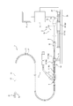
- FIG. 9 is an external view showing a state immediately before a pullback operation is performed on the diagnostic imaging catheter according to the embodiment of the present invention by an external device.
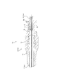
- FIG. 6 is an external view showing a state at the end of the pullback operation started from the state shown in FIG. 1. It is sectional drawing which shows the peripheral part of a relay connector of the state shown in FIG. It is sectional drawing which shows the peripheral part of a relay connector of the state shown in FIG. It is sectional drawing which shows the peripheral part of a unit connector in the state where a drive shaft and a support tube are in a backward limit position. It is sectional drawing which shows the peripheral part of a relay connector in the state where a drive shaft and a support tube are in a backward limit position.
- an image diagnostic catheter 1 (hereinafter, also referred to as a catheter 1) according to the present embodiment is used in combination with an external device 2, a control device 3, and a display 4 so that it can be used in a living body such as a human body. It is possible to capture an image of the inside of a blood vessel such as a blood vessel and display the image. That is, the catheter 1, the external device 2, the control device 3, and the display 4 constitute an image diagnostic device.
- An image diagnostic apparatus including the catheter 1 and the external device 2 may be configured by integrating the control device 3 and the display 4 with the external device 2.
- the catheter 1 has a sheath 5, a relay connector 6, an outer tube 7, a unit connector 8, a hub 9, an inner tube 10, a support tube 11, and a drive shaft 12.
- the distal end of the relay connector 6 is integrally connected to the proximal end of the sheath 5.
- the distal end of the outer tube 7 is integrally connected to the base end of the relay connector 6.
- the distal end of the unit connector 8 is integrally connected to the proximal end of the outer tube 7.
- the base end of the inner tube 10 is integrally connected to the tip of the hub 9.
- the base end portion of the support tube 11 is integrally connected to the tip end portion of the inner tube 10.
- the drive shaft 12 has an elongated shape having a central axis X1.
- the base end of the drive shaft 12 is rotatably supported by the hub 9 about the central axis X1.
- the drive shaft 12 has a signal transmitting/receiving unit 13 at its tip.
- the signal transmitting/receiving unit 13 is capable of transmitting a signal (inspection wave) such as an ultrasonic signal or an optical signal to a blood vessel and receiving a reflected signal thereof.
- a signal line (not shown) that enables communication between the signal transmitting/receiving unit 13 and the control device 3 via the external device 2 is provided inside the drive shaft 12, a signal line (not shown) that enables communication between the signal transmitting/receiving unit 13 and the control device 3 via the external device 2 is provided.
- the signal transmitting/receiving unit 13 can rotate integrally with the drive shaft 12 about the central axis X1.
- the drive shaft 12 is inserted into the sheath 5, the relay connector 6, the outer tube 7, the unit connector 8, the support tube 11, the inner tube 10 and the hub 9.
- the hub 9, the inner tube 10, the support tube 11, and the drive shaft 12 are integrally advanced and retracted relative to the sheath 5, the relay connector 6, the outer tube 7, and the unit connector 8. It is movable (that is, movable forward and movable backward). Forward movement means movement from the base end side to the tip end side, and backward movement means movement in the opposite direction. The front is the direction from the base end side to the tip end side, and the rear is the opposite direction.
- the inner tube 10 constitutes a telescope section 14 together with the relay connector 6 and the outer tube 7.
- the telescope section 14 has an inner cylinder 14a composed of the inner tube 10 and an outer cylinder 14b composed of the relay connector 6 and the outer tube 7.
- the telescope part 14 can be expanded and contracted by the forward and backward movement of the inner cylinder 14a inside the outer cylinder 14b.
- the telescope unit 14 is capable of expanding and contracting between a contraction limit state in which further contraction is restricted and an extension limit state in which further expansion is restricted.
- the telescope portion 14 is configured such that the distal end surface of the hub 9 comes into contact with the base end surface of the unit connector 8 to enter a contraction limit state.
- the telescope unit 14 may be configured to be in a contraction limit state by contacting other surfaces.
- the telescope portion 14 is in the extension limit state when the step surface 10a provided at the distal end portion of the inner tube 10 contacts the step surface 8a provided inside the unit connector 8. Is configured.
- the step surface 10a of the inner tube 10 and the step surface 8a of the unit connector 8 each have an annular shape whose diameter increases from the base end side toward the tip end side.
- the telescope unit 14 may be configured to be in the extension limit state by contact between other surfaces.
- the hub 9, the inner tube 10, the support tube 11, and the drive shaft 12 have a forward limit position (see FIG. 1) in which the telescope portion 14 is in the contraction limit state and a backward limit position (see FIG. 1) in which the telescope portion 14 is in the extension limit state ( (See FIG. 5) and can be moved back and forth.
- the base end portion of the support tube 11 is fixed to the tip end surface of the inner tube 10 with an adhesive 15.
- the base end portion of the support tube 11 and the tip end portion of the inner tube 10 may be fixed to each other by a fixing means other than the adhesive 15 such as welding.
- the unit connector 8 is composed of a front end side member 8b having a male screw portion and a base end side member 8c having a female screw portion screwed with the male screw portion.
- the number of members forming the unit connector 8 can be increased or decreased as appropriate.
- the external device 2 includes a rotation drive unit 2a that rotationally drives the drive shaft 12, and an advance/retreat moving mechanism 2b that moves the drive shaft 12 forward and backward.
- the rotary drive unit 2a has a housing 2c to which the hub 9 can be attached and detached, and a main shaft 2d which is arranged inside the housing 2c and to which the drive shaft 12 can be attached and detached.
- the main shaft 2d is connected to the base end portion of the drive shaft 12 via a connector (not shown) that is rotatably supported in the hub 9 about the central axis X1 so that communication inside the drive shaft 12 is performed.
- the line can be communicatively connected to the control device 3.
- the main shaft 2d can be rotated about the central axis X1 by rotating the main shaft 2d about the central axis X1 by a rotary drive source 2e such as a motor in a state of being connected to the drive shaft 12. ..
- the forward/backward moving mechanism 2b includes a housing 2c of the rotary drive unit 2a, a rotary drive source 2f such as a motor, a ball screw mechanism 2g for moving the housing 2c forward/backward by the rotary drive source 2f, and a base supporting the ball screw mechanism 2g. 2h and a unit connector fixing portion 2i integrally connected to the base 2h.
- the ball screw mechanism 2g includes a screw shaft 2j that is pivotally supported by the base 2h and is rotationally driven by the rotary drive source 2f, and a nut 2k fixed to the housing 2c.
- the unit connector fixing portion 2i can fix the unit connector 8 by detachably engaging with the unit connector 8.
- the external device 2 is driven by the rotary drive unit 2a from the drive shaft 12 in the forward limit position as shown in FIG. 1 in response to the control signal from the control device 3 with the catheter 1 attached. As shown in FIG. 2, while rotating, a pullback operation can be performed to move the drive shaft 12 backward to a predetermined position before the backward limit position.
- the rotation speed of the drive shaft 12 is, for example, 1800 rpm.
- the control device 3 is composed of, for example, a processor such as a CPU.
- the signal transmission/reception unit 13 transmits a signal (inspection wave) to the vessel while rotating and receives the reflected signal.
- the signal transmitting/receiving unit 13 transmits a measurement signal based on the received signal to the control device 3 through a signal line inside the drive shaft 12.
- the control device 3 causes the display 4 to display a vascular image based on the measurement signal.
- the catheter 1 requires a priming process that fills the lumen 5a (see FIG. 3) of the sheath 5 with a priming solution such as a physiological saline solution, which is performed prior to the imaging of the blood vessel by the pullback operation. Therefore, as shown in FIG. 3, the relay connector 6 has a side pipe 6b that partitions the priming liquid injection port 6a at the base end. The tip of the side pipe 6b is integrally connected to the main shaft 6c into which the drive shaft 12, the support tube 11 and the sheath 5 are inserted.
- a seal member 16 that seals between the main tube 6c and the support tube 11 is disposed inside the main tube 6c behind the proximal end 5b of the sheath 5.
- An X ring is used as the seal member 16.
- the seal member 16 may be an O-ring, for example.
- the main tube 6c has a main lumen 6d extending from the seal member 16 to the base end 5b of the sheath 5 defined therein.
- the side tube 6b communicates with the main lumen 6d at the communication port 6e and defines an injection lumen 6f into which the priming liquid can be injected.
- the communication port 6e is located at the tip of the injection lumen 6f, and the injection port 6a is located at the base end of the injection lumen 6f.
- a priming liquid supply device 17 (see FIG. 1) for supplying a priming liquid is connected to the base end of the side pipe 6b.
- the priming liquid supply device 17 includes a syringe 17a and a connection tube member 17b.
- the connection tube member 17b includes a proximal connector 17c that is connected to the distal end of the syringe 17a, a distal connector 17d that is connected to the proximal end of the side tube 6b, and extends from the proximal connector 17c to the distal connector 17d.
- the existing tube 17e The existing tube 17e.
- the relay connector 6 is composed of a first member 18 and a second member 19.
- the 1st member 18 has the main cylinder 18a which divides the main lumen 6d inside, and the side cylinder 18b which divides the injection lumen 6f inside.
- the outer peripheral surface of the base end of the sheath 5 is fixed to the inner peripheral surface of the main cylinder 18a at the distal end by a fixing means such as welding.
- the base end 5b of the sheath 5 is abutted against an annular step surface provided on the inner peripheral surface of the tip end of the main cylinder 18a.
- a kink suppressing tube 20 is provided on the outer periphery of the proximal end portion of the sheath 5 along the axial direction.
- the proximal end 5b of the sheath 5 projects from the proximal end 20a of the kink suppressing tube 20 to the proximal end side.
- the inner peripheral surface of the kink suppression tube 20 is fixed to the outer peripheral surface of the proximal end portion of the sheath 5 by a fixing means such as welding.
- the outer peripheral surface at the base end of the kink suppressing tube 20 is fixed to the inner peripheral surface at the front end of the main cylinder 18a by a fixing means such as welding.
- the distal end 6l of the main lumen 6d and the proximal end 5d of the lumen 5a of the sheath 5 are flush with each other (that is, they are smoothly connected).
- a reduced diameter portion 6g that gradually decreases in diameter toward the front.
- the main lumen 6d has a circular cross-sectional shape that has a constant shape and size in the axial direction from the reduced diameter portion 6g to the seal member 16.
- the main cylinder 18a is provided at its base end portion with a diameter-expanded inner peripheral surface 18c which is stepped from the base end of the main lumen 6d.
- the seal member 16 is arranged at the tip of the radially expanded inner peripheral surface 18c.
- a female screw portion 18d is provided on a portion of the radially expanded inner peripheral surface 18c closer to the base end than the seal member 16.
- the male screw portion 19a provided on the outer peripheral surface of the distal end portion of the cylindrical second member 19 is screwed into the female screw portion 18d.
- the inner peripheral surface of the second member 19 is provided with a reduced diameter portion 19b that gradually decreases in diameter toward the front.
- An outer peripheral surface of the distal end portion of the outer tube 7 is fixed to a portion of the inner peripheral surface of the second member 19 closer to the base end side than the reduced diameter portion 19b by a fixing means such as welding.
- the sheath 5 has a long cylindrical shape, and a lumen 5a is defined inside the sheath 5.
- the distal end 5c of the sheath 5 is provided with a distal end wall defining a discharge port (not shown) capable of discharging the priming liquid from the lumen 5a.
- the tip wall may be formed integrally with the sheath 5, or may be formed separately from the sheath 5 and fixed to the tip of the sheath 5 by a fixing means such as welding.
- the distal end 5c of the sheath 5 is provided with a tubular guided portion 21 into which a guide wire can be inserted.
- the base end of the second member 19 and the outer tube The tip portion of 7 is fixed to each other after its relative axial position is adjusted.
- the main lumen 6d extends concentrically with the central axis X1.
- the injection lumen 6f has a central axis line X2.
- the central axis line X2 intersects the central axis line X1 so as to form an acute angle on the base end side of the central axis line X1.
- the injection lumen 6f has a frustoconical diameter-reduced portion 6h whose diameter gradually decreases from the base end side toward the tip side along the central axis X2 up to the communication port 6e.
- the shape of the reduced diameter portion 6h is not limited to the truncated cone shape.
- the injection lumen 6f is not limited to the one having the reduced diameter portion 6h.
- the central axis line X2 may not intersect with the central axis line X1.
- the support tube 11 is provided on the outer periphery of the drive shaft 12 along the axial direction and is configured to move forward and backward in conjunction with the drive shaft 12. More specifically, the support tube 11 moves back and forth integrally with the drive shaft 12 as described above.
- the tip end 11a of the support tube 11 is movable to a position forward of the front end 6i of the communication port 6e. That is, the tip end 11a of the support tube 11 can move to a position in front of the same position P as the front end 6i of the communication port 6e in the front-rear direction. Therefore, as shown in FIG. 4, it is possible to perform the pullback operation such that the tip end 11a of the support tube 11 is located in front of the position P when the pullback operation by the external device 2 is completed. More specifically, the tip 11a of the support tube 11 is movable to a position in front of the tip 6j of the relay connector 6, as shown in FIG.
- the support tube 11 accommodates the drive shaft 12 with a slight gap (not shown) that allows smooth rotation of the drive shaft 12 and suppresses local deformation of the drive shaft 12. .. Therefore, the support tube 11 is interposed between the rotating drive shaft 12 and the communication port 6e, so that the drive shaft 12 enters the communication port 6e while deforming in a tongue shape, and a malfunction such as a screw breakage occurs. Occurrence can be suppressed.
- By controlling the pullback operation such that the tip end 11a of the support tube 11 is located in front of the position P at the end of the pullback operation, it is possible to suppress the occurrence of such a malfunction.
- the external device 2 restricts the distal end of the support tube 11 of the catheter 1 from moving to a position rearward of the front end of the communication port 6e when the catheter 1 is attached (see FIGS. 1 and 2). May have. With such a restriction unit 2l, the occurrence of the above-described malfunction can be suppressed.
- the restriction unit 21 may be configured to be able to remove such restriction.
- the control device 3 is configured to control so that the rotary drive unit 2a that rotationally drives the drive shaft 12 is not driven when the tip of the support tube 11 is located rearward of the front end of the communication port 6e. Good. With such a configuration of the control device 3, it is possible to suppress the occurrence of the above-described malfunction.
- the tip 11a of the support tube 11 is movable to a position rearward of the front end 6i of the communication port 6e. That is, the tip end 11a of the support tube 11 can move to a position rearward of the position P. More specifically, the tip end 11a of the support tube 11 is located rearward of the front end 6i of the communication port 6e at the backward travel position (extended end state of the telescope portion 14). Therefore, by performing the priming process with the tip 11a of the support tube 11 moved to a position rearward of the position P, the flow resistance of the priming liquid flowing into the main lumen 6d from the communication port 6e is reduced, and the priming process is performed. Can be done smoothly.
- the priming liquid flows until it is discharged from the discharge port provided at the tip of the lumen 5a while sequentially filling the injection lumen 6f, the main lumen 6d, and the lumen 5a, so that the injection lumen 6f, the main lumen 6d, and The air inside the lumen 5a is discharged from the discharge port.
- the tip end 11a of the support tube 11 can be moved to a position behind the rear end 6k of the communication port 6e. That is, the front end 11a of the support tube 11 is located rearward of the rear end 6k of the communication port 6e in the backward travel position, as shown in FIG.
- the tip 11a of the support tube 11 may be moved to a position rearward of the front end 6i of the communication port 6e, but can be moved to a position rearward of the center of the communication port 6e in order to further reduce the flow path resistance. (Rearward of the center of the communication port 6e in the backward limit position), and is movable to a position rearward of the rear end 6k of the communication port 6e (rear end 6k of the communication port 6e in the backward limit position). It is more preferable that it is located rearward).
- the tip 11a of the support tube 11 is located in front of the seal member 16 at the backward travel position, as shown in FIG.
- the tip end 11a of the support tube 11 is smoothly guided to the tip end 6l of the main lumen 6d by the reduced diameter portion 6g, and the lumen 5a
- the front end 11a of the support tube 11 can be smoothly guided to the inside of the lumen 5a by the front end 6l of the main lumen 6d that is flush with the base end 5d.
- the relay connector 6 (first member 18, second member 19), the support tube 11, and the sheath 5 are preferably made of synthetic resin, but are not limited thereto.
Landscapes
- Health & Medical Sciences (AREA)
- Life Sciences & Earth Sciences (AREA)
- Heart & Thoracic Surgery (AREA)
- Veterinary Medicine (AREA)
- Public Health (AREA)
- General Health & Medical Sciences (AREA)
- Animal Behavior & Ethology (AREA)
- Engineering & Computer Science (AREA)
- Biomedical Technology (AREA)
- Biophysics (AREA)
- Surgery (AREA)
- Medical Informatics (AREA)
- Physics & Mathematics (AREA)
- Molecular Biology (AREA)
- Pathology (AREA)
- Radiology & Medical Imaging (AREA)
- Nuclear Medicine, Radiotherapy & Molecular Imaging (AREA)
- Pulmonology (AREA)
- Anesthesiology (AREA)
- Hematology (AREA)
- Optics & Photonics (AREA)
- Vascular Medicine (AREA)
- Ultra Sonic Daignosis Equipment (AREA)
- Endoscopes (AREA)
Abstract
画像診断用カテーテルは、先端部に信号送受信部を備える回転及び進退移動可能な駆動シャフトと、前記駆動シャフトの外周に軸方向に沿って設けられるとともに前記駆動シャフトに連動して進退移動するサポートチューブと、前記駆動シャフトが挿入されるシースと、前記シースの基端に連結される中継コネクタと、前記シースの基端より後方において、前記中継コネクタと前記サポートチューブとの間をシールするシール部材と、を有し、前記中継コネクタは、前記シール部材から前記シースの前記基端まで延在する主ルーメンと、前記主ルーメンと連通口において連通するとともにプライミング液を注入可能な注入ルーメンと、を区画し、前記サポートチューブの先端は、前記連通口の前端より後方の位置に移動可能である。
Description
本開示は、画像診断用カテーテル及び画像診断装置に関する。
先端部に信号送受信部が設けられるとともに回転及び進退移動可能な駆動シャフトと、駆動シャフトが挿入されるシースと、を有する画像診断用カテーテルが知られている。画像診断用カテーテルには、超音波などの信号を円滑に送受信するため等の目的で、使用に先立ってシースのルーメンを生理食塩液などのプライミング液で満たすプライミング処理を必要とするものがある。
例えば、特許文献1には、シースの基端に連結される中継コネクタにプライミング液の注入口を設けることにより、プライミング液の流路抵抗を低減して容易なプライミング処理を可能にした画像診断用カテーテルが記載されている。この画像診断用カテーテルは、駆動シャフトの外周に軸方向に沿って設けられるとともに駆動シャフトに連動して進退移動するサポートチューブを有している。中継コネクタは、中継コネクタとサポートチューブとの間をシールするシール部材からシースの基端まで延在する主ルーメンと、主ルーメンと連通口において連通するとともにプライミング液を注入可能な注入ルーメンと、を区画している。
特許文献1に記載される画像診断用カテーテルは、駆動シャフト及びサポートチューブが最も基端側に引かれたときであっても、サポートチューブの先端が連通口の前端より前方に位置するように構成されている。そのため、このような画像診断用カテーテルには、プライミング液の流路抵抗をさらに低減する余地がある。
本開示は、このような点に鑑み、プライミング液の流路抵抗を低減して円滑なプライミング処理を可能にできる画像診断用カテーテル及び画像診断装置を提供することを目的とする。
本発明の第1態様としての画像診断用カテーテルは、
先端部に信号送受信部を備える回転及び進退移動可能な駆動シャフトと、
前記駆動シャフトの外周に軸方向に沿って設けられるとともに前記駆動シャフトに連動して進退移動するサポートチューブと、
前記駆動シャフトが挿入されるシースと、
前記シースの基端に連結される中継コネクタと、
前記シースの基端より後方において、前記中継コネクタと前記サポートチューブとの間をシールするシール部材と、を有し、
前記中継コネクタは、前記シール部材から前記シースの前記基端まで延在する主ルーメンと、前記主ルーメンと連通口において連通するとともにプライミング液を注入可能な注入ルーメンと、を区画し、
前記サポートチューブの先端は、前記連通口の前端より後方の位置に移動可能である。
先端部に信号送受信部を備える回転及び進退移動可能な駆動シャフトと、
前記駆動シャフトの外周に軸方向に沿って設けられるとともに前記駆動シャフトに連動して進退移動するサポートチューブと、
前記駆動シャフトが挿入されるシースと、
前記シースの基端に連結される中継コネクタと、
前記シースの基端より後方において、前記中継コネクタと前記サポートチューブとの間をシールするシール部材と、を有し、
前記中継コネクタは、前記シール部材から前記シースの前記基端まで延在する主ルーメンと、前記主ルーメンと連通口において連通するとともにプライミング液を注入可能な注入ルーメンと、を区画し、
前記サポートチューブの先端は、前記連通口の前端より後方の位置に移動可能である。
本発明の1つの実施形態として、前記サポートチューブの先端は、前記連通口の前端より前方の位置に移動可能である。
本発明の1つの実施形態として、前記サポートチューブの先端は、外部装置によるプルバック操作の終了時に前記連通口の前記前端より前方に位置する。
本発明の1つの実施形態として、前記中継コネクタの前記主ルーメンの先端と前記シースのルーメンの基端とは、面一である。
本発明の第2態様としての画像診断装置は、
画像診断用カテーテルと、該画像診断用カテーテルを取り付け可能な外部装置と、を備える画像診断装置であって、
前記画像診断用カテーテルは、
先端部に信号送受信部を備える回転及び進退移動可能な駆動シャフトと、
前記駆動シャフトの外周に軸方向に沿って設けられるとともに前記駆動シャフトに連動して進退移動するサポートチューブと、
前記駆動シャフトが挿入されるシースと、
前記シースの基端に連結される中継コネクタと、
前記シースの基端より後方において、前記中継コネクタと前記サポートチューブとの間をシールするシール部材と、を有し、
前記中継コネクタは、前記シール部材から前記シースの前記基端まで延在する主ルーメンと、前記主ルーメンと連通口において連通するとともにプライミング液を注入可能な注入ルーメンと、を区画し、
前記サポートチューブの先端は、前記連通口の前端より後方の位置に移動可能であり、
前記外部装置は、前記画像診断用カテーテルが取り付けられた状態において、前記画像診断用カテーテルの前記サポートチューブの先端が前記連通口の前端より後方の位置に移動することを制限する制限部を有する。
画像診断用カテーテルと、該画像診断用カテーテルを取り付け可能な外部装置と、を備える画像診断装置であって、
前記画像診断用カテーテルは、
先端部に信号送受信部を備える回転及び進退移動可能な駆動シャフトと、
前記駆動シャフトの外周に軸方向に沿って設けられるとともに前記駆動シャフトに連動して進退移動するサポートチューブと、
前記駆動シャフトが挿入されるシースと、
前記シースの基端に連結される中継コネクタと、
前記シースの基端より後方において、前記中継コネクタと前記サポートチューブとの間をシールするシール部材と、を有し、
前記中継コネクタは、前記シール部材から前記シースの前記基端まで延在する主ルーメンと、前記主ルーメンと連通口において連通するとともにプライミング液を注入可能な注入ルーメンと、を区画し、
前記サポートチューブの先端は、前記連通口の前端より後方の位置に移動可能であり、
前記外部装置は、前記画像診断用カテーテルが取り付けられた状態において、前記画像診断用カテーテルの前記サポートチューブの先端が前記連通口の前端より後方の位置に移動することを制限する制限部を有する。
本開示によれば、プライミング液の流路抵抗を低減して円滑なプライミング処理を可能にできる画像診断用カテーテル及び画像診断装置を提供することができる。
以下、図面を参照して、本発明の一実施形態に係る画像診断用カテーテル及び画像診断装置について詳細に例示説明する。
図1に示すように、本実施形態に係る画像診断用カテーテル1(以下、カテーテル1ともいう)は、外部装置2、制御装置3、及びディスプレイ4とともに使用されることで、人体等の生体における血管等の脈管の内部を撮像しその画像を表示することができる。すなわち、カテーテル1、外部装置2、制御装置3、及びディスプレイ4で画像診断装置を構成している。制御装置3及びディスプレイ4を外部装置2に一体化することなどにより、カテーテル1及び外部装置2からなる画像診断装置を構成してもよい。カテーテル1は、シース5、中継コネクタ6、外チューブ7、ユニットコネクタ8、ハブ9、内チューブ10、サポートチューブ11、及び駆動シャフト12を有している。
シース5の基端部には中継コネクタ6の先端部が一体に連結されている。中継コネクタ6の基端部には外チューブ7の先端部が一体に連結されている。外チューブ7の基端部にはユニットコネクタ8の先端部が一体に連結されている。
ハブ9の先端部には内チューブ10の基端部が一体に連結されている。内チューブ10の先端部にはサポートチューブ11の基端部が一体に連結されている。
駆動シャフト12は、中心軸線X1を有する長尺状をなしている。駆動シャフト12の基端部は、ハブ9に中心軸線X1を中心に回転可能に軸支されている。駆動シャフト12は、先端部に信号送受信部13を有している。信号送受信部13は、超音波信号又は光信号などの信号(検査波)を脈管に対して送信するとともにその反射信号を受信可能である。駆動シャフト12の内部には、外部装置2を介した信号送受信部13と制御装置3との通信を可能にする信号線(図示省略)が設けられている。信号送受信部13は駆動シャフト12と一体に中心軸線X1を中心として回転することができる。
駆動シャフト12は、シース5、中継コネクタ6、外チューブ7、ユニットコネクタ8、サポートチューブ11、内チューブ10及びハブ9に挿入されている。
図1~図2に示すように、ハブ9、内チューブ10、サポートチューブ11及び駆動シャフト12は、シース5、中継コネクタ6、外チューブ7及びユニットコネクタ8に対して相対的に、一体に進退移動可能(つまり、前進移動可能且つ後進移動可能)である。前進移動とは、基端側から先端側への移動を意味し、後進移動とは、その反対方向への移動を意味する。前方とは、基端側から先端側へ向かう方向であり、後方とはその反対方向である。
内チューブ10は、中継コネクタ6及び外チューブ7とともにテレスコープ部14を構成している。テレスコープ部14は、内チューブ10で構成される内筒14aと、中継コネクタ6及び外チューブ7で構成される外筒14bと、を有している。テレスコープ部14は、外筒14bの内部における内筒14aの進退移動により、伸縮可能である。
テレスコープ部14は、それ以上の収縮が規制される収縮限状態と、それ以上の伸長が規制される伸長限状態との間で伸縮可能である。テレスコープ部14は、図1に示すように、ハブ9の先端面がユニットコネクタ8の基端面に当接することで収縮限状態となるように構成されている。テレスコープ部14は、これ以外の面同士の当接によって収縮限状態となるように構成されてもよい。テレスコープ部14は、図5に示すように、内チューブ10の先端部に設けられた段差面10aがユニットコネクタ8の内部に設けられた段差面8aに当接することで伸長限状態となるように構成されている。内チューブ10の段差面10a及びユニットコネクタ8の段差面8aは、それぞれ、基端側から先端側に向けて拡径する環状をなしている。テレスコープ部14は、これ以外の面同士の当接によって伸長限状態となるように構成されてもよい。
ハブ9、内チューブ10、サポートチューブ11及び駆動シャフト12は、テレスコープ部14が収縮限状態となる前進限位置(図1参照)と、テレスコープ部14が伸長限状態となる後進限位置(図5参照)との間で進退移動可能である。
図5に示すように、サポートチューブ11の基端部は、内チューブ10の先端面に接着剤15によって固着されている。サポートチューブ11の基端部と内チューブ10の先端部とは、接着剤15以外の、溶着等の固着手段によって互いに固着されてもよい。ユニットコネクタ8は、雄ねじ部を有する先端側部材8bと、この雄ねじ部と螺合する雌ねじ部を有する基端側部材8cとで構成されている。しかし、ユニットコネクタ8を構成する部材の数は適宜増減が可能である。
図1に示すように、外部装置2は、駆動シャフト12を回転駆動する回転駆動部2aと、駆動シャフト12を進退移動する進退移動機構2bと、を有している。
回転駆動部2aは、ハブ9を着脱可能なハウジング2cと、ハウジング2cの内部に配置されるとともに、駆動シャフト12を着脱可能な主軸2dと、を有している。主軸2dは、ハブ9の内部に中心軸線X1を中心に回転可能に軸支されたコネクタ(図示省略)を介して駆動シャフト12の基端部と連結することで、駆動シャフト12の内部の通信線を制御装置3と通信可能に接続することができる。また、主軸2dは、駆動シャフト12と連結した状態で、モータなどの回転駆動源2eによって中心軸線X1を中心に回転することで、駆動シャフト12を、中心軸線X1を中心に回転させることができる。
進退移動機構2bは、回転駆動部2aのハウジング2cと、モータなどの回転駆動源2fと、ハウジング2cを回転駆動源2fにより進退移動させるボールねじ機構2gと、ボールねじ機構2gを支持する基台2hと、基台2hに一体に連結するユニットコネクタ固定部2iと、を有している。ボールねじ機構2gは、基台2hに軸支されるとともに回転駆動源2fによって回転駆動されるねじ軸2jと、ハウジング2cに固定されたナット2kと、で構成されている。ユニットコネクタ固定部2iは、ユニットコネクタ8と着脱可能に係合することでユニットコネクタ8を固定可能である。
外部装置2は、カテーテル1が取り付けられた状態で、制御装置3からの制御信号により、図1に示すように駆動シャフト12が前進限位置にある状態から、駆動シャフト12を回転駆動部2aにより回転しながら、図2に示すように、駆動シャフト12を後進限位置より手前の所定位置まで後進移動させるプルバック操作を行うことができる。駆動シャフト12の回転速度は、例えば1800rpmである。制御装置3は、例えばCPUなどのプロセッサで構成されている。
プルバック操作の開始から終了まで、信号送受信部13は、回転しながら脈管に対して信号(検査波)を送信し、その反射信号を受信する。信号送受信部13は、この受信信号に基づく測定信号を駆動シャフト12の内部の信号線を通じて制御装置3に送信する。制御装置3は、測定信号に基づく脈管の画像をディスプレイ4に表示させる。
カテーテル1は、プルバック操作による脈管の撮像に先立って行われる、シース5のルーメン5a(図3参照)を生理食塩液などのプライミング液で満たすプライミング処理を必要とする。このため、図3に示すように、中継コネクタ6は、プライミング液の注入口6aを基端に区画する側管6bを有している。側管6bの先端は、駆動シャフト12、サポートチューブ11及びシース5が挿入される主管6cに一体に連なっている。
主管6cの内部には、シース5の基端5bより後方において主管6cとサポートチューブ11との間をシールするシール部材16が配置されている。シール部材16としてはXリングが用いられている。シール部材16は、例えばOリングであってもよい。
主管6cは、シール部材16からシース5の基端5bまで延在する主ルーメン6dを内部に区画している。側管6bは、主ルーメン6dと連通口6eにおいて連通するとともにプライミング液を注入可能な注入ルーメン6fを内部に区画している。注入ルーメン6fの先端に連通口6eが位置し、注入ルーメン6fの基端に注入口6aが位置している。
側管6bの基端には、プライミング液を供給するプライミング液供給装置17(図1参照)が接続されている。プライミング液供給装置17は、シリンジ17aと、接続チューブ部材17bと、で構成されている。接続チューブ部材17bは、シリンジ17aの先端部に接続される基端側コネクタ17cと、側管6bの基端に接続される先端側コネクタ17dと、基端側コネクタ17cから先端側コネクタ17dまで延在するチューブ17eと、を有している。
図3に示すように、中継コネクタ6は、第1部材18と、第2部材19と、で構成されている。第1部材18は、主ルーメン6dを内部に区画する主筒18aと、注入ルーメン6fを内部に区画する側筒18bと、を有している。
主筒18aの先端部における内周面には、シース5の基端部の外周面が溶着などの固着手段によって固着されている。シース5の基端5bは、主筒18aの先端部における内周面に設けられた円環状の段差面に突き当てられている。シース5の基端部の外周には、軸方向に沿ってキンク抑制用チューブ20が設けられている。シース5の基端5bは、キンク抑制用チューブ20の基端20aから基端側に飛び出ている。キンク抑制用チューブ20の内周面は、シース5の基端部の外周面に溶着などの固着手段によって固着されている。キンク抑制用チューブ20の基端部における外周面は、主筒18aの先端部における内周面に溶着などの固着手段によって固着されている。
主ルーメン6dの先端6lと、シース5のルーメン5aの基端5dとは、面一である(つまり、滑らかに連なっている)。主ルーメン6dの先端部には、前方に向けて徐々に縮径する縮径部6gが設けられている。主ルーメン6dは、縮径部6gからシール部材16まで軸方向に亘って一定の形状及び大きさとなる円形の断面形状を有している。
主筒18aの基端部には、主ルーメン6dの基端から段差状に拡径した拡径内周面18cが設けられている。拡径内周面18cの先端には、シール部材16が配置されている。拡径内周面18cにおけるシール部材16より基端側の部分には、雌ねじ部18dが設けられている。
雌ねじ部18dには、筒状の第2部材19の先端部における外周面に設けられた雄ねじ部19aが螺合している。第2部材19の内周面には、前方に向けて徐々に縮径する縮径部19bが設けられている。第2部材19の内周面における縮径部19bより基端側の部分には、外チューブ7の先端部における外周面が溶着などの固着手段によって固着されている。
シース5は、長尺円筒状をなしており、その内部にルーメン5aを区画している。シース5の先端5cには、ルーメン5aからプライミング液を排出可能な排出口(図示省略)を区画する先端壁が設けられている。先端壁は、シース5と一体に成形されていてもよいし、シース5と別体に成形され、シース5の先端に溶着などの固着手段によって固着されていてもよい。シース5の先端5cには、ガイドワイヤを挿入可能な筒状の被案内部21が設けられている。
各部材の長さにおける製造誤差を吸収し、被案内部21の先端からユニットコネクタ8の基端までの全長を仕様どおりの寸法に調整するために、第2部材19の基端部と外チューブ7の先端部とは、その相対的な軸方向位置が調節された上で、互いに固着されている。
主ルーメン6dは、中心軸線X1と同心状に延在している。注入ルーメン6fは、中心軸線X2を有している。中心軸線X2は、中心軸線X1の基端側に鋭角を形成するように、中心軸線X1と交差している。注入ルーメン6fは、連通口6eまで中心軸線X2に沿って基端側から先端側に向けて徐々に縮径する切頭円錐状の縮径部6hを有している。縮径部6hの形状は切頭円錐状に限らない。注入ルーメン6fは、縮径部6hを有するものに限らない。中心軸線X2は、中心軸線X1と交差していなくてもよい。
サポートチューブ11は、駆動シャフト12の外周に軸方向に沿って設けられるとともに駆動シャフト12に連動して進退移動するように構成されている。より具体的には、サポートチューブ11は、前述したように駆動シャフト12と一体に進退移動する。
サポートチューブ11の先端11aは、連通口6eの前端6iより前方の位置に移動可能である。つまり、サポートチューブ11の先端11aは、前後方向における連通口6eの前端6iと同じ位置Pより前方の位置に移動可能である。したがって、図4に示すように、外部装置2によるプルバック操作の終了時にサポートチューブ11の先端11aが位置Pより前方に位置するように、プルバック操作を行うことが可能である。より具体的には、サポートチューブ11の先端11aは、図3に示すように、中継コネクタ6の先端6jより前方の位置に移動可能である。
サポートチューブ11は、駆動シャフト12の円滑な回転を許容するとともに駆動シャフト12の局所的な変形を抑制することができる程度の僅かな隙間(図示省略)を空けて駆動シャフト12を収容している。したがって、サポートチューブ11は、回転する駆動シャフト12と連通口6eとの間に介在することにより、駆動シャフト12がトグロ状に変形しながら連通口6eに入り込み、ねじ切れたりするなどの作動不良の発生を抑制することができる。プルバック操作の終了時にサポートチューブ11の先端11aが位置Pより前方に位置するようにプルバック操作を制御することにより、このような作動不良の発生を抑制することができる。
外部装置2は、カテーテル1が取り付けられた状態において、カテーテル1のサポートチューブ11の先端が連通口6eの前端より後方の位置に移動することを制限する制限部2l(図1、図2参照)を有していてもよい。このような制限部2lにより、上述した作動不良の発生を抑制することができる。制限部2lは、このような制限を解除できるように構成されていてもよい。
制御装置3は、サポートチューブ11の先端が連通口6eの前端よりも後方に位置しているときに、駆動シャフト12を回転駆動する回転駆動部2aが駆動しないように制御するよう構成されていてもよい。制御装置3のこのような構成により、上述した作動不良の発生を抑制することができる。
図6に示すように、サポートチューブ11の先端11aは、連通口6eの前端6iより後方の位置に移動可能である。つまり、サポートチューブ11の先端11aは、位置Pより後方の位置に移動可能である。より具体的には、サポートチューブ11の先端11aは、後進限位置(テレスコープ部14の伸長限状態)において連通口6eの前端6iより後方に位置する。したがって、サポートチューブ11の先端11aを位置Pより後方の位置に移動させた状態でプライミング処理を行うことにより、連通口6eから主ルーメン6dに流入するプライミング液の流路抵抗を低減し、プライミング処理を円滑に行うことができる。プライミング処理において、プライミング液は、注入ルーメン6f、主ルーメン6d及びルーメン5aを順次満たしながら、ルーメン5aの先端に設けられた排出口から排出されるまで流れることで、注入ルーメン6f、主ルーメン6d及びルーメン5aの内部の空気を排出口から排出する。
サポートチューブ11の先端11aは、より具体的には、連通口6eの後端6kより後方の位置に移動可能である。つまり、サポートチューブ11の先端11aは、図6に示すように、後進限位置において連通口6eの後端6kより後方に位置する。
サポートチューブ11の先端11aは、連通口6eの前端6iより後方の位置に移動可能であればよいが、流路抵抗をより低減するためには、連通口6eの中心より後方の位置に移動可能である(後進限位置において連通口6eの中心より後方に位置する)ことが好ましく、連通口6eの後端6kより後方の位置に移動可能である(後進限位置において連通口6eの後端6kより後方に位置する)ことがより好ましい。
サポートチューブ11の先端11aは、図6に示すように、後進限位置においてシール部材16より前方に位置する。
プライミング処理後に駆動シャフト12及びサポートチューブ11を前進限位置まで前進移動させる際には、縮径部6gによってサポートチューブ11の先端11aを主ルーメン6dの先端6lまで円滑に案内し、さらに、ルーメン5aの基端5dと面一な主ルーメン6dの先端6lによってサポートチューブ11の先端11aをルーメン5aの内部まで円滑に案内することができる。
中継コネクタ6(第1部材18、第2部材19)、サポートチューブ11、シース5は、それぞれ、合成樹脂製であることが好ましいが、これに限らない。
前述した実施形態は、本発明の実施形態の一例にすぎず、発明の要旨を逸脱しない範囲で種々変更可能であることはいうまでもない。
1 画像診断用カテーテル
2 外部装置
2a 回転駆動部
2b 進退移動機構
2c ハウジング
2d 主軸
2e 回転駆動源
2f 回転駆動源
2g ボールねじ機構
2h 基台
2i ユニットコネクタ固定部
2j ねじ軸
2k ナット
2l 制限部
3 制御装置
4 ディスプレイ
5 シース
5a ルーメン
5b シースの基端
5c シースの先端
5d ルーメンの基端
6 中継コネクタ
6a 注入口
6b 側管
6c 主管
6d 主ルーメン
6e 連通口
6f 注入ルーメン
6g 縮径部
6h 縮径部
6i 連通口の前端
6j 中継コネクタの先端
6k 連通口の後端
6l 主ルーメンの先端
7 外チューブ
8 ユニットコネクタ
8a 段差面
8b 先端側部材
8c 基端側部材
9 ハブ
10 内チューブ
10a 段差面
11 サポートチューブ
11a サポートチューブの先端
12 駆動シャフト
13 信号送受信部
14 テレスコープ部
14a 内筒
14b 外筒
15 接着剤
16 シール部材
17 プライミング液供給装置
17a シリンジ
17b 接続チューブ部材
17c 基端側コネクタ
17d 先端側コネクタ
17e チューブ
18 第1部材
18a 主筒
18b 側筒
18c 拡径内周面
18d 雌ねじ部
19 第2部材
19a 雄ねじ部
19b 縮径部
20 キンク抑制用チューブ
20a キンク抑制用チューブの基端
21 被案内部
X1、X2 中心軸線
P 位置
2 外部装置
2a 回転駆動部
2b 進退移動機構
2c ハウジング
2d 主軸
2e 回転駆動源
2f 回転駆動源
2g ボールねじ機構
2h 基台
2i ユニットコネクタ固定部
2j ねじ軸
2k ナット
2l 制限部
3 制御装置
4 ディスプレイ
5 シース
5a ルーメン
5b シースの基端
5c シースの先端
5d ルーメンの基端
6 中継コネクタ
6a 注入口
6b 側管
6c 主管
6d 主ルーメン
6e 連通口
6f 注入ルーメン
6g 縮径部
6h 縮径部
6i 連通口の前端
6j 中継コネクタの先端
6k 連通口の後端
6l 主ルーメンの先端
7 外チューブ
8 ユニットコネクタ
8a 段差面
8b 先端側部材
8c 基端側部材
9 ハブ
10 内チューブ
10a 段差面
11 サポートチューブ
11a サポートチューブの先端
12 駆動シャフト
13 信号送受信部
14 テレスコープ部
14a 内筒
14b 外筒
15 接着剤
16 シール部材
17 プライミング液供給装置
17a シリンジ
17b 接続チューブ部材
17c 基端側コネクタ
17d 先端側コネクタ
17e チューブ
18 第1部材
18a 主筒
18b 側筒
18c 拡径内周面
18d 雌ねじ部
19 第2部材
19a 雄ねじ部
19b 縮径部
20 キンク抑制用チューブ
20a キンク抑制用チューブの基端
21 被案内部
X1、X2 中心軸線
P 位置
Claims (5)
- 先端部に信号送受信部を備える回転及び進退移動可能な駆動シャフトと、
前記駆動シャフトの外周に軸方向に沿って設けられるとともに前記駆動シャフトに連動して進退移動するサポートチューブと、
前記駆動シャフトが挿入されるシースと、
前記シースの基端に連結される中継コネクタと、
前記シースの基端より後方において、前記中継コネクタと前記サポートチューブとの間をシールするシール部材と、を有し、
前記中継コネクタは、前記シール部材から前記シースの前記基端まで延在する主ルーメンと、前記主ルーメンと連通口において連通するとともにプライミング液を注入可能な注入ルーメンと、を区画し、
前記サポートチューブの先端は、前記連通口の前端より後方の位置に移動可能である、画像診断用カテーテル。 - 前記サポートチューブの先端は、前記連通口の前端より前方の位置に移動可能である、請求項1に記載の画像診断用カテーテル。
- 前記サポートチューブの先端は、外部装置によるプルバック操作の終了時に前記連通口の前記前端より前方に位置する、請求項2に記載の画像診断用カテーテル。
- 前記中継コネクタの前記主ルーメンの先端と前記シースのルーメンの基端とは、面一である、請求項1~3のいずれか一項に記載の画像診断用カテーテル。
- 画像診断用カテーテルと、該画像診断用カテーテルを取り付け可能な外部装置と、を備える画像診断装置であって、
前記画像診断用カテーテルは、
先端部に信号送受信部を備える回転及び進退移動可能な駆動シャフトと、
前記駆動シャフトの外周に軸方向に沿って設けられるとともに前記駆動シャフトに連動して進退移動するサポートチューブと、
前記駆動シャフトが挿入されるシースと、
前記シースの基端に連結される中継コネクタと、
前記シースの基端より後方において、前記中継コネクタと前記サポートチューブとの間をシールするシール部材と、を有し、
前記中継コネクタは、前記シール部材から前記シースの前記基端まで延在する主ルーメンと、前記主ルーメンと連通口において連通するとともにプライミング液を注入可能な注入ルーメンと、を区画し、
前記サポートチューブの先端は、前記連通口の前端より後方の位置に移動可能であり、
前記外部装置は、前記画像診断用カテーテルが取り付けられた状態において、前記画像診断用カテーテルの前記サポートチューブの先端が前記連通口の前端より後方の位置に移動することを制限する制限部を有する、
画像診断装置。
Priority Applications (3)
| Application Number | Priority Date | Filing Date | Title |
|---|---|---|---|
| JP2020566513A JP7342039B2 (ja) | 2019-01-17 | 2020-01-17 | 画像診断用カテーテル及び画像診断装置 |
| CN202080009147.0A CN113301857B (zh) | 2019-01-17 | 2020-01-17 | 图像诊断用导管以及图像诊断装置 |
| US17/377,982 US12350095B2 (en) | 2019-01-17 | 2021-07-16 | Diagnostic imaging catheter and diagnostic imaging apparatus |
Applications Claiming Priority (2)
| Application Number | Priority Date | Filing Date | Title |
|---|---|---|---|
| JP2019006437 | 2019-01-17 | ||
| JP2019-006437 | 2019-03-27 |
Related Child Applications (1)
| Application Number | Title | Priority Date | Filing Date |
|---|---|---|---|
| US17/377,982 Continuation US12350095B2 (en) | 2019-01-17 | 2021-07-16 | Diagnostic imaging catheter and diagnostic imaging apparatus |
Publications (1)
| Publication Number | Publication Date |
|---|---|
| WO2020149416A1 true WO2020149416A1 (ja) | 2020-07-23 |
Family
ID=71613379
Family Applications (1)
| Application Number | Title | Priority Date | Filing Date |
|---|---|---|---|
| PCT/JP2020/001609 Ceased WO2020149416A1 (ja) | 2019-01-17 | 2020-01-17 | 画像診断用カテーテル及び画像診断装置 |
Country Status (4)
| Country | Link |
|---|---|
| US (1) | US12350095B2 (ja) |
| JP (1) | JP7342039B2 (ja) |
| CN (1) | CN113301857B (ja) |
| WO (1) | WO2020149416A1 (ja) |
Cited By (4)
| Publication number | Priority date | Publication date | Assignee | Title |
|---|---|---|---|---|
| CN113100713A (zh) * | 2021-04-09 | 2021-07-13 | 谢荣荣 | 一种基于大数据的牙齿形态扫描装置 |
| WO2021140839A1 (ja) * | 2020-01-06 | 2021-07-15 | テルモ株式会社 | カテーテル組立体及び結束方法 |
| CN116981408A (zh) * | 2021-02-26 | 2023-10-31 | 泰尔茂株式会社 | 图像诊断用导管 |
| US12023054B2 (en) | 2018-09-28 | 2024-07-02 | Scp Altis | Catheter apparatus |
Families Citing this family (4)
| Publication number | Priority date | Publication date | Assignee | Title |
|---|---|---|---|---|
| CN114557727B (zh) * | 2021-12-30 | 2022-09-20 | 上海睿刀医疗科技有限公司 | 鞘管装置以及超声检测系统 |
| WO2023129722A1 (en) | 2021-12-31 | 2023-07-06 | Boston Scientific Scimed, Inc. | Systems and methods for vascular image co-registration |
| WO2023215558A1 (en) | 2022-05-06 | 2023-11-09 | Boston Scientific Scimed, Inc. | Intravascular imaging devices |
| CN223716193U (zh) * | 2024-10-23 | 2025-12-26 | 常州市第一人民医院 | 一种应用于经皮肾镜的输尿管导管 |
Citations (2)
| Publication number | Priority date | Publication date | Assignee | Title |
|---|---|---|---|---|
| JPH10272137A (ja) * | 1997-03-30 | 1998-10-13 | Terumo Corp | 超音波カテーテル |
| JP2017205430A (ja) * | 2016-05-20 | 2017-11-24 | テルモ株式会社 | 画像診断用カテーテル |
Family Cites Families (8)
| Publication number | Priority date | Publication date | Assignee | Title |
|---|---|---|---|---|
| JP2012223346A (ja) * | 2011-04-19 | 2012-11-15 | Terumo Corp | カテーテル |
| WO2014188509A1 (ja) * | 2013-05-21 | 2014-11-27 | テルモ株式会社 | カテーテル |
| EP3103403A4 (en) * | 2014-02-06 | 2017-12-20 | Nipro Corporation | Catheter |
| US20160374710A1 (en) * | 2014-03-12 | 2016-12-29 | Yegor D. Sinelnikov | Carotid body ablation with a transvenous ultrasound imaging and ablation catheter |
| US20170055941A1 (en) * | 2015-09-02 | 2017-03-02 | Koninklijke Philips N.V. | Integrated imaging component and intravascular device delivery system |
| JP2017056142A (ja) * | 2015-09-18 | 2017-03-23 | テルモ株式会社 | 画像診断用カテーテル |
| JP6779890B2 (ja) * | 2015-09-18 | 2020-11-04 | テルモ株式会社 | 画像診断用カテーテル |
| WO2017164071A1 (ja) * | 2016-03-22 | 2017-09-28 | テルモ株式会社 | カテーテル及び画像診断装置 |
-
2020
- 2020-01-17 WO PCT/JP2020/001609 patent/WO2020149416A1/ja not_active Ceased
- 2020-01-17 JP JP2020566513A patent/JP7342039B2/ja active Active
- 2020-01-17 CN CN202080009147.0A patent/CN113301857B/zh active Active
-
2021
- 2021-07-16 US US17/377,982 patent/US12350095B2/en active Active
Patent Citations (2)
| Publication number | Priority date | Publication date | Assignee | Title |
|---|---|---|---|---|
| JPH10272137A (ja) * | 1997-03-30 | 1998-10-13 | Terumo Corp | 超音波カテーテル |
| JP2017205430A (ja) * | 2016-05-20 | 2017-11-24 | テルモ株式会社 | 画像診断用カテーテル |
Cited By (6)
| Publication number | Priority date | Publication date | Assignee | Title |
|---|---|---|---|---|
| US12023054B2 (en) | 2018-09-28 | 2024-07-02 | Scp Altis | Catheter apparatus |
| US12295599B2 (en) | 2018-09-28 | 2025-05-13 | Scp Altis | Catheter apparatus |
| WO2021140839A1 (ja) * | 2020-01-06 | 2021-07-15 | テルモ株式会社 | カテーテル組立体及び結束方法 |
| JP7470717B2 (ja) | 2020-01-06 | 2024-04-18 | テルモ株式会社 | カテーテル組立体及び結束方法 |
| CN116981408A (zh) * | 2021-02-26 | 2023-10-31 | 泰尔茂株式会社 | 图像诊断用导管 |
| CN113100713A (zh) * | 2021-04-09 | 2021-07-13 | 谢荣荣 | 一种基于大数据的牙齿形态扫描装置 |
Also Published As
| Publication number | Publication date |
|---|---|
| CN113301857B (zh) | 2024-04-09 |
| CN113301857A (zh) | 2021-08-24 |
| JPWO2020149416A1 (ja) | 2021-11-25 |
| US20210338199A1 (en) | 2021-11-04 |
| US12350095B2 (en) | 2025-07-08 |
| JP7342039B2 (ja) | 2023-09-11 |
Similar Documents
| Publication | Publication Date | Title |
|---|---|---|
| JP7342039B2 (ja) | 画像診断用カテーテル及び画像診断装置 | |
| EP2934653B1 (en) | Rotational ultrasound imaging catheter with extended catheter body telescope | |
| US11717259B2 (en) | Diagnostic imaging catheter | |
| US8905936B2 (en) | Catheter having a biasing member | |
| JP5576665B2 (ja) | 生体内診断装置およびその制御方法 | |
| US11317890B2 (en) | Catheter and imaging apparatus for diagnosis | |
| WO2017047330A1 (ja) | 画像診断用カテーテル | |
| JP7853278B2 (ja) | 画像診断用カテーテル | |
| JP2015066036A (ja) | 画像診断用カテーテル | |
| JP7618513B2 (ja) | 画像診断用カテーテル | |
| WO2015119153A1 (ja) | カテーテル | |
| US20180214670A1 (en) | Diagnostic imaging catheter | |
| WO2023008539A1 (ja) | 画像診断用カテーテル | |
| JP7776487B2 (ja) | 画像診断用カテーテル | |
| JP6251093B2 (ja) | カテーテル | |
| HK40104095A (zh) | 图像诊断用导管 | |
| WO2022071157A1 (ja) | 駆動シャフト及び画像診断用カテーテル | |
| HK40103918A (zh) | 图像诊断用导管 | |
| JP7227052B2 (ja) | 画像診断装置、画像診断システム及びプライミング方法 | |
| JP2023038812A (ja) | 画像診断用カテーテル | |
| WO2015107833A1 (ja) | 画像診断用カテーテル | |
| JP7470717B2 (ja) | カテーテル組立体及び結束方法 | |
| JP7032505B2 (ja) | 画像診断用カテーテル | |
| WO2014162492A1 (ja) | 画像診断用カテーテル | |
| JP2024172739A (ja) | カテーテル、及び医療デバイス |
Legal Events
| Date | Code | Title | Description |
|---|---|---|---|
| 121 | Ep: the epo has been informed by wipo that ep was designated in this application |
Ref document number: 20742066 Country of ref document: EP Kind code of ref document: A1 |
|
| ENP | Entry into the national phase |
Ref document number: 2020566513 Country of ref document: JP Kind code of ref document: A |
|
| NENP | Non-entry into the national phase |
Ref country code: DE |
|
| 122 | Ep: pct application non-entry in european phase |
Ref document number: 20742066 Country of ref document: EP Kind code of ref document: A1 |