WO2020149293A1 - 駆動装置 - Google Patents
駆動装置 Download PDFInfo
- Publication number
- WO2020149293A1 WO2020149293A1 PCT/JP2020/001023 JP2020001023W WO2020149293A1 WO 2020149293 A1 WO2020149293 A1 WO 2020149293A1 JP 2020001023 W JP2020001023 W JP 2020001023W WO 2020149293 A1 WO2020149293 A1 WO 2020149293A1
- Authority
- WO
- WIPO (PCT)
- Prior art keywords
- connector
- base portion
- motor
- unit
- cover
- Prior art date
Links
Images


Classifications
-
- B—PERFORMING OPERATIONS; TRANSPORTING
- B62—LAND VEHICLES FOR TRAVELLING OTHERWISE THAN ON RAILS
- B62D—MOTOR VEHICLES; TRAILERS
- B62D5/00—Power-assisted or power-driven steering
- B62D5/04—Power-assisted or power-driven steering electrical, e.g. using an electric servo-motor connected to, or forming part of, the steering gear
- B62D5/0403—Power-assisted or power-driven steering electrical, e.g. using an electric servo-motor connected to, or forming part of, the steering gear characterised by constructional features, e.g. common housing for motor and gear box
- B62D5/0406—Power-assisted or power-driven steering electrical, e.g. using an electric servo-motor connected to, or forming part of, the steering gear characterised by constructional features, e.g. common housing for motor and gear box including housing for electronic control unit
-
- B—PERFORMING OPERATIONS; TRANSPORTING
- B62—LAND VEHICLES FOR TRAVELLING OTHERWISE THAN ON RAILS
- B62D—MOTOR VEHICLES; TRAILERS
- B62D5/00—Power-assisted or power-driven steering
- B62D5/04—Power-assisted or power-driven steering electrical, e.g. using an electric servo-motor connected to, or forming part of, the steering gear
- B62D5/0421—Electric motor acting on or near steering gear
- B62D5/0424—Electric motor acting on or near steering gear the axes of motor and final driven element of steering gear, e.g. rack, being parallel
-
- H—ELECTRICITY
- H02—GENERATION; CONVERSION OR DISTRIBUTION OF ELECTRIC POWER
- H02K—DYNAMO-ELECTRIC MACHINES
- H02K11/00—Structural association of dynamo-electric machines with electric components or with devices for shielding, monitoring or protection
- H02K11/30—Structural association with control circuits or drive circuits
- H02K11/33—Drive circuits, e.g. power electronics
-
- H—ELECTRICITY
- H02—GENERATION; CONVERSION OR DISTRIBUTION OF ELECTRIC POWER
- H02K—DYNAMO-ELECTRIC MACHINES
- H02K5/00—Casings; Enclosures; Supports
- H02K5/04—Casings or enclosures characterised by the shape, form or construction thereof
- H02K5/10—Casings or enclosures characterised by the shape, form or construction thereof with arrangements for protection from ingress, e.g. water or fingers
-
- H—ELECTRICITY
- H02—GENERATION; CONVERSION OR DISTRIBUTION OF ELECTRIC POWER
- H02K—DYNAMO-ELECTRIC MACHINES
- H02K5/00—Casings; Enclosures; Supports
- H02K5/04—Casings or enclosures characterised by the shape, form or construction thereof
- H02K5/22—Auxiliary parts of casings not covered by groups H02K5/06-H02K5/20, e.g. shaped to form connection boxes or terminal boxes
- H02K5/225—Terminal boxes or connection arrangements
-
- H—ELECTRICITY
- H02—GENERATION; CONVERSION OR DISTRIBUTION OF ELECTRIC POWER
- H02P—CONTROL OR REGULATION OF ELECTRIC MOTORS, ELECTRIC GENERATORS OR DYNAMO-ELECTRIC CONVERTERS; CONTROLLING TRANSFORMERS, REACTORS OR CHOKE COILS
- H02P25/00—Arrangements or methods for the control of AC motors characterised by the kind of AC motor or by structural details
- H02P25/16—Arrangements or methods for the control of AC motors characterised by the kind of AC motor or by structural details characterised by the circuit arrangement or by the kind of wiring
-
- H—ELECTRICITY
- H02—GENERATION; CONVERSION OR DISTRIBUTION OF ELECTRIC POWER
- H02K—DYNAMO-ELECTRIC MACHINES
- H02K2213/00—Specific aspects, not otherwise provided for and not covered by codes H02K2201/00 - H02K2211/00
- H02K2213/03—Machines characterised by numerical values, ranges, mathematical expressions or similar information
Definitions
- the present disclosure relates to a drive device.
- Patent Document 1 discloses a drive device used in an electric power steering device.
- the motor has two winding sets.
- the control device includes a control unit having an inverter corresponding to each winding set, and a connector unit for connecting the control unit to the outside.
- the present disclosure has been made in view of the above points, and an object thereof is to provide a drive device in which an increase in the radial size is suppressed.
- the drive device of the present disclosure includes a motor, a control unit that is disposed coaxially with the motor, controls the drive of the motor, a connector unit that connects the control unit to an external connector, and a member separate from the connector unit. And a seal member provided between the connector unit and the cover.
- the connector unit has a base part, a connector part having a connection opening to an external connector, and a connector fixing part for fixing the base part.
- the axial silhouette of the base portion has a shape elongated in a predetermined direction.
- the connector fixing portion is formed so as to protrude radially outward from the base portion within an angle range of ⁇ 45° about the rotation axis with respect to the short axis of the axial silhouette of the base portion.
- the inside of the cover can have a waterproof structure.
- the entire connector unit has a circular silhouette. Can fit in. Therefore, even if the number of terminals of the connector unit is increased, it is possible to prevent the drive device from increasing in size in the radial direction.
- FIG. 1 is a configuration diagram of an electric power steering device to which the drive device of each embodiment is applied
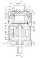
- FIG. 2 is a vertical cross-sectional view of the drive device
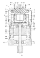
- 3 is a sectional view taken along line III-III of FIG.
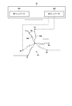
- FIG. 4 is a schematic diagram showing the configuration of a polyphase coaxial motor
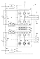
- FIG. 5 is a circuit configuration diagram of the driving device according to the first embodiment
- FIG. 6 is a control block diagram of the driving device according to the first embodiment.
- FIG. 7 is a top view of the connector unit of the drive device according to the first embodiment, and is a view taken in the direction of arrow VII of FIG.
- FIG. 1 is a configuration diagram of an electric power steering device to which the drive device of each embodiment is applied
- FIG. 2 is a vertical cross-sectional view of the drive device
- 3 is a sectional view taken along line III-III of FIG.
- FIG. 4 is a schematic diagram showing the configuration of a polyphase coaxial motor
- FIG. 5 is a circuit
- FIG. 8 is a top view of the connector unit of the driving device according to the second embodiment
- FIG. 9 is a top view of the connector unit of the drive device according to the third embodiment
- FIG. 10 is a top view of the connector unit of the driving device according to the fourth embodiment
- FIG. 11 is a top view of the connector unit of the driving device according to the fifth embodiment
- FIG. 12 is a top view of the connector unit of the driving device according to the sixth embodiment
- FIG. 13 is a top view of the connector unit of the driving device according to the seventh embodiment.
- the drive device is applied to an electric power steering device of a vehicle and outputs steering assist torque.
- FIG. 1 shows the overall configuration of a steering system 99 including an electric power steering device 90.
- the electric power steering device 90 in FIG. 1 is a rack assist type electric power steering device, it is similarly applicable to a column assist type electric power steering device.
- the steering system 99 includes a steering wheel 91, a steering shaft 92, a pinion gear 96, a rack shaft 97, wheels 98, an electric power steering device 90, and the like.
- a steering shaft 92 is connected to the handle 91.
- the pinion gear 96 provided at the tip of the steering shaft 92 meshes with the rack shaft 97.
- a pair of wheels 98 are provided at both ends of the rack shaft 97 via tie rods or the like.
- the electric power steering device 90 includes a steering torque sensor 93, a control device 10, a motor 80, a speed reducer 94, and the like.
- the steering torque sensor 93 is provided in the middle of the steering shaft 92 and detects the steering torque of the driver.
- the duplicated steering torque sensor 93 includes a first torque sensor 931 and a second torque sensor 932, and double-detects the first steering torque trq1 and the second steering torque trq2.
- one detection value of the steering torque trq may be commonly used for the two systems.
- the control device 10 acquires the steering torques trq1 and trq2 detected by the steering torque sensor 93 and the electric angles ⁇ 1 and ⁇ 2 of the motor 80 detected by the rotation angle sensor.
- the control device 10 controls the drive of the motor 80 so as to generate a desired assist torque, based on these information and information such as the motor current detected inside the control device 10.
- the assist torque output by the motor 80 is transmitted to the rack shaft 97 via the speed reducer 94.
- the control device 10 is integrally configured on one side in the axial direction of the motor 80.
- the motor 80 and the control device 10 constitute the electromechanical integrated drive device 1.
- the control device 10 is arranged coaxially with the motor 80 on the side opposite to the output side of the motor 80.
- the control device 10 may be arranged coaxially with the motor 80 on the output side of the motor 80.
- the motor 80 is a three-phase brushless motor and includes a stator 840, a rotor 860, and a housing 830 that houses them.
- the stator 840 has a stator core 845 fixed to the housing 830 and two three-phase winding groups 801 and 802 assembled to the stator core 845.
- Lead wires 851, 853, and 855 extend from each phase winding forming the first winding set 801.
- Lead wires 852, 854, and 856 extend from each phase winding forming the second winding set 802.
- the rotor 860 has a shaft 87 supported by a rear bearing 835 and a front bearing 836, and a rotor core 865 in which the shaft 87 is fitted.
- the rotor 860 is provided inside the stator 840 and can rotate relative to the stator 840.
- a permanent magnet 88 is provided at one end of the shaft 87.
- the housing 830 has a cylindrical case 834, a rear frame end 837 provided at one end of the case 834, and a front frame end 838 provided at the other end of the case 834.
- the rear frame end 837 and the front frame end 838 are fastened to each other by bolts or the like.
- the lead wires 851, 852, etc. of each winding set 801, 802 are inserted into the lead wire insertion hole 839 of the rear frame end 837 and connected to the control device 10.
- the winding groups 801 and 802 have the same electrical characteristics and are arranged on the common stator core 845 with an electrical angle difference of 30 [deg] from each other.
- the control device 10 includes a control unit 20, a cover 21 that covers the control unit 20, and a connector unit for connecting the control unit 20 to external connectors 161 and 162 (see FIG. 1). 35 and a seal member 22 provided between the connector unit 35 and the cover 21.
- the external connectors 161 and 162 are connectors for external cables.
- the cover 21 protects the control unit 20 from an external impact and prevents dust, water, and the like from entering the control unit 20.
- the control unit 20 includes a heat sink 245 fixed to the rear frame end 837, substrates 230 and 235 and power modules 241, 242 fixed to the heat sink 245, and various electronic components mounted on the substrates 230 and 235. It has and. 2 and 3, electronic components are not shown. Electronic components will be described later with reference to FIGS.
- the power modules 241, 242 have switching elements, which will be described later, and are connected to the lead wires 852, 856, etc. of the winding groups 801, 802.
- the heat sink 245 is provided in the cover 21 between the rear frame end 837 and the connector unit 35, and is fixed by the screw 156.
- the substrate 230 is provided at a position facing the rear frame end 837.
- the board 235 is provided at a position facing the connector unit 35.
- the boards 230 and 235 are provided with electronic components for two systems independently for each system, and form a redundant configuration.
- FIG. 5 shows the circuit configuration of the driving device 1.
- the control unit 20 is a two-system motor control unit including two inverters 601, 602 as “power converters” and two microcomputers 401, 402, and a motor having two winding sets 801 and 802. Power 80.
- the unit of the constituent elements including the winding set, the inverter and the microcomputer is defined as "system”.
- a component or signal of the first system is prefixed with “first” or “first system”, and a component or signal of the second system is prefixed with “second”. Or “second line” is added for distinction. Matters common to each system are collectively described without adding “first and second” and “first and second systems”. Further, except for the components of the switching element and the connector unit, “1” is added to the end of the reference numerals of the components or signals of the first system, and “2” is added to the end of the reference symbols of the components or signals of the second system. I will add it.
- the control unit 20 includes inverters 601, 602, power supply relays 141, 142, rotation angle detection units 251, 252, microcomputers 401, 402, etc.
- electric power is supplied to each system from two power sources 111 and 112.
- the inverters 601 and 602 are respectively bridge-connected with six switching elements 611 to 616 and 621 to 626 such as MOSFETs.
- the first inverter 601 performs a switching operation according to the drive signal from the first microcomputer 401, converts the DC power of the first power supply 111, and supplies the DC power to the first winding group 801.
- the second inverter 602 performs a switching operation according to the drive signal from the second microcomputer 402, converts the DC power of the second power supply 112, and supplies the DC power to the second winding group 802.
- the power supply relays 141 and 142 are provided in the power supply line of each input unit of the inverters 601 and 602.
- the power supply relays 141 and 142 illustrated in FIG. 5 include a protection function when the power supply is reversely connected, in which two switching elements having parasitic diodes opposite to each other are connected in series.
- the power relay may be composed of one switching element or a mechanical relay that does not include the reverse connection prevention function.
- capacitors 281 and 282 are provided at the input parts of the inverters 601 and 602. The capacitors 281 and 282 smooth the electric power input from the power source, and also prevent the outflow of noise due to the switching operation of the switching element and the like. Further, the capacitors 281 and 282 form a filter circuit together with an inductor (not shown).
- the first rotation angle detection unit 251 detects the electrical angle ⁇ 1 of the motor 80 and outputs it to the first microcomputer 401.
- the second rotation angle detection unit 252 detects the electrical angle ⁇ 2 of the motor 80 and outputs it to the second microcomputer 402.
- the first rotation angle detection unit 251 has a power supply line and a signal line that are independent of the second rotation angle detection unit 252.
- the first rotation angle detection unit 251 and the second rotation angle detection unit are packaged together to form the rotation angle sensor 25.
- the first microcomputer 401 calculates a drive signal for instructing the first inverter 601 based on the feedback information such as the steering torque trq1, the current Im1, and the rotation angle ⁇ 1.
- the second microcomputer 402 calculates a drive signal for instructing the second inverter 602 based on the feedback information such as the steering torque trq2, the current Im2, and the rotation angle ⁇ 2.
- FIG. 6 shows the control configuration of the driving device 1.
- the first system and the second system are all composed of two independent element groups, and have a redundant configuration.
- each electronic component of the first system that controls energization of the winding set 801 constitutes a first system control unit 201.
- each electronic component of the second system that controls energization of the winding set 802 constitutes a second system control unit 202.
- the connector unit 35 is connected to the first system terminal group connected to the first system control unit 201, the first system connector 351 that holds the first system terminal group, and the second system control unit 202. It has a second system terminal group and a second system connector 352 that holds the second system terminal group.
- First power supply terminals that is, first power supply bus bars 121 and 131 for supplying power to the first system control unit 201, and a first system terminal for inputting a signal to the first system control unit 201.
- the one-vehicle communication terminal 311 and the first torque signal terminal 331 are included.
- the second system terminals (second power supply bus bars) 122 and 132 for supplying power to the second system control unit 202 and the second system terminal for inputting a signal to the second system control unit 202 are connected to the second system terminals.
- a two-vehicle communication terminal 312 and a second torque signal terminal 332 are included.
- the first power supply terminals 121 and 131 are connected to the first power supply 111.
- the power of the first power supply 111 is supplied to the first winding group 801 via the first power supply terminals 121 and 131, the first power supply relay 141 and the first inverter 601. Further, the electric power of the first power supply 111 is also supplied to the first microcomputer 401 and the sensors of the first system.
- the second power supply terminals 122 and 132 are connected to the second power supply 112.
- the power of the second power supply 112 is supplied to the second winding set 802 via the second power supply terminals 122 and 132, the second power supply relay 142, and the second inverter 602.
- the power of the second power supply 112 is also supplied to the second microcomputer 402 and the sensors of the second system.
- the first vehicle communication terminal 311 is connected between the first CAN 301 and the first vehicle communication circuit 321.
- the second vehicle communication terminal 312 is connected between the second CAN 302 and the second vehicle communication circuit 322.
- the vehicle communication terminals 311 and 312 of the two systems may be connected to a common CAN.
- any standard network such as CAN-FD (CAN with Flexible Data rate) or FlexRay may be used.
- the first torque signal terminal 331 is connected between the first torque sensor 931 and the first torque sensor input circuit 341.
- the first torque sensor input circuit 341 notifies the first microcomputer 401 of the steering torque trq1 detected by the first torque signal terminal 331.
- the second torque signal terminal 332 is connected between the second torque sensor 932 and the second torque sensor input circuit 342.
- the second torque sensor input circuit 342 notifies the second microcomputer 402 of the steering torque trq2 detected by the second torque signal terminal 332.
- the microcomputers 401 and 402 can exchange information with each other through communication between the microcomputers.
- the control unit 20 continues the motor control in the other normal system.
- the configuration of the connector unit 35 is shown in FIGS. 2, 3 and 7.
- the direction parallel to the axis Ax of the motor 80 will be referred to as “axial direction”.
- the direction orthogonal to the axis Ax of the motor 80 will be referred to as “radial direction”.
- the connector unit 35 has a base portion 350, a connector portion 351, a connector fixing portion 354, a cover fixing portion 355, and each system terminal group.
- the base portion 350 is provided inside the opening portion 211 of the cover 21.
- the connector portion 351 has two connectors 351 and 352. The connectors 351 and 352 project from the base portion 350 through the opening portion 211 to the outside of the cover 21 in the axial direction.
- the first system connector 351 has a connection opening 356 to the external connector 161.
- First power supply terminals 121 and 131, a first vehicle communication terminal 311 and a first torque signal terminal 331 are arranged in the connection frontage 356.
- the second system connector 352 has a connection opening 357 to the external connector 162.
- Second power supply terminals 122 and 132, a second vehicle communication terminal 312, and a second torque signal terminal 332 are arranged in the connection frontage 357.
- the connector fixing portion 354 is formed so as to protrude radially outward from the base portion 350.
- the connector unit 35 is fixed to the heat sink 245 with a screw 157 that is inserted through the connector fixing portion 354.
- the cover fixing portion 355 is formed radially outside the connector portion 351 of the base portion 350.
- the cover 21 is fixed to the cover fixing portion 355 with a screw 155.
- the axial silhouette of the base portion 350 has a shape that is elongated in the predetermined direction X.
- the two connectors 351 and 352 are arranged side by side in the longitudinal direction of the axial silhouette of the base portion 350.
- the connector fixing portion 354 is formed so as to protrude radially outward from the base portion 350 within an angle range Aa of ⁇ 45° about the rotation axis Ax with respect to the short axis LS of the axial silhouette of the base portion 350.
- the fact that the connector fixing portion 354 is within the angular range Aa means that the connector fixing portion 354 is arranged closer to the short axis line LS than the long axis line LL of the axial silhouette of the base portion 350.
- the connector fixing portion 354 is provided so as to overlap the short axis line LS.
- the base part 350 has an elliptical silhouette in the axial direction.
- an elliptical seal groove 358 for the seal member 22 is formed on the outer peripheral portion of the base portion 350 located outside the connection openings 356 and 357.
- the circular seal member 22 is housed in the seal groove 358.
- the connector arrangement area Ac When the area in which the connector portion 351 is arranged in the axial direction is the connector arrangement area Ac, the connector arrangement area Ac has a shape elongated in the predetermined direction X. Specifically, the connector arrangement region Ac is a rectangular shape including a pair of long sides SL parallel to the long axis LL of the axial silhouette of the base portion 350 and a pair of short sides SS parallel to the short axis LS. ..
- the cover fixing portion 355 is provided between the pair of long sides SL and the seal member 22, and one between the pair of short sides SS and the seal member 22.
- the four cover fixing portions 355 are arranged on the long axis LL or the short axis LS, and are provided at equal angular intervals around the rotation axis Ax.
- the axial silhouette of the base portion 350 has a shape that is elongated in the predetermined direction X.
- the connector fixing portion 354 is formed so as to protrude radially outward from the base portion 350 within an angle range Aa of ⁇ 45° about the rotation axis Ax with respect to the short axis LS of the axial silhouette of the base portion 350. There is.
- the inside of the cover 21 can have a waterproof structure.
- the connector unit 354 is arranged closer to the short axis LS than the long axis LL of the axial silhouette of the base 350 while increasing the terminal arrangement space by making the base 350 long.
- the entire 35 can fit within the circular silhouette. Therefore, even if the number of terminals of the connector unit 35 is increased, it is possible to suppress an increase in the radial size of the drive device 1. In other words, the mountability is improved by optimizing the arrangement of the base portion and the connector fixing portion and reducing the radial size of the drive device 1.
- the axial silhouette of the base portion 350 has an elliptical shape. Further, an elliptical seal groove 358 for the seal member 22 is formed on the outer peripheral portion of the base portion 350. This makes it possible to use a general-purpose O-ring for the seal member 22, and it is not necessary to align the direction when assembling.
- the connector arrangement area Ac when the area where the connector portion 351 is arranged in the axial direction is the connector arrangement area Ac, the connector arrangement area Ac has a shape that is elongated in the predetermined direction X.
- the arrangement of the connector portion 351 is optimized with respect to the elongated base portion 350, and the connector arrangement area Ac can be made as large as possible.
- the radial physique of the drive device 1 can be downsized.
- the connector arrangement region Ac is a rectangular shape including a pair of long sides SL parallel to the long axis LL of the axial silhouette of the base portion 350 and a pair of short sides SS parallel to the short axis LS.
- the shape As a result, the arrangement of the connector portion 351 is optimized with respect to the elongated base portion 350, and the connector arrangement area Ac can be made as large as possible.
- one cover fixing portion 355 is provided between the pair of long sides SL and the seal member 22, and one cover fixing portion 355 is provided between the pair of short sides SS and the seal member 22.
- the cover fixing portions 355 can be arranged substantially uniformly around the rotation axis Ax. Therefore, the waterproof property can be improved by uniformly compressing the seal member 22.
- the base portion 350 can be made as small as possible. Thereby, the radial physique of the drive device 1 can be reduced.
- the two connectors 351 and 352 are arranged so as to be aligned in the longitudinal direction of the axial silhouette of the base portion 350. As a result, two connectors 351 and 352 having the same size can be arranged in the longitudinal connector arrangement area Ac without waste.
- the axial silhouette of the base portion 360 has a shape that is elongated in the predetermined direction X and has a rectangular shape with rounded corners.
- the seal groove 368 has a rectangular shape with rounded corners.
- the base portion 360 is not limited to the elliptical shape and may be a rectangular shape.
- the second embodiment has the same configuration as the first embodiment and has the same effects as the first embodiment.
- the connector portion 371 has one connector 372.
- the connector 372 has a connection opening 376.
- illustration of each system terminal is omitted.
- the number of connectors of the connector portion 371 is not limited to two and may be one.
- the third embodiment has the same configuration as the first embodiment, and has the same effects as the first embodiment.
- the connector unit 381 has three connectors 382, 383, 384.
- the connectors 382, 383, 384 have connection openings 386, 387, 388, and are arranged so as to be aligned in the longitudinal direction of the axial silhouette of the base portion 350.
- the number of connectors of the connector unit 381 is not limited to two, and may be three or four or more.
- the fourth embodiment has the same configuration as the first embodiment, and has the same effects as the first embodiment.
- the connector section 391 has two connectors 392 and 393.
- the connectors 392 and 393 have connection fronts 396 and 397, and are arranged so as to be aligned in the lateral direction of the axial silhouette of the base portion 350.
- the connector arrangement direction of the connector portion 391 is not limited to the longitudinal direction, but may be the lateral direction or another direction.
- the fifth embodiment has the same configuration as that of the first embodiment and has the same effect as that of the first embodiment.
- the connector section 501 has two connectors 502 and 503.
- the connectors 502 and 503 have connection openings 506 and 507.
- the connector 502 is larger than the connector 503 and has a different shape.
- the connector 502 is L-shaped, and the connector 503 is rectangular.
- the size and shape of each connector of the connector unit 501 may be different.
- the sixth embodiment has the same configuration as the first embodiment, and has the same effects as the first embodiment.
- the connector unit 511 has two connectors 512 and 513.
- the connectors 512 and 513 have connection fronts 516 and 517.
- the connectors 512 and 513 are arranged on both sides of the minor axis LS, and are arranged so that their longitudinal directions intersect with each other.
- the connector arrangement region Ac has a shape that is elongated in the predetermined direction X, and has a trapezoidal shape that includes an upper base SU, a lower base SD, and two legs SS.
- Three cover fixing portions 355 are provided.
- One cover fixing portion 355 is provided between the leg SS and the seal groove 358, one between the other leg SS and the seal groove 358, and one between the lower bottom SD and the seal groove 358. Are arranged. As described above, the number of cover fixing portions 355 is not limited to four, and may be three or may be five or more. Except for the above, the seventh embodiment has the same configuration as the first embodiment, and has the same effects as the first embodiment.
- the connector placement area does not necessarily have a shape that is elongated in the predetermined direction, and need not have a rectangular shape.
- the motor may have two winding sets arranged in phase.
- the number of phases of the motor is not limited to three and may be four or more.
- the motor to be driven is not limited to the AC brushless motor, but may be a DC motor with a brush. In that case, an H bridge circuit may be used as the “power converter”.
- the drive device is not limited to the electric power steering device, and may be applied to any other application.
Landscapes
- Engineering & Computer Science (AREA)
- Power Engineering (AREA)
- Chemical & Material Sciences (AREA)
- Combustion & Propulsion (AREA)
- Transportation (AREA)
- Mechanical Engineering (AREA)
- Microelectronics & Electronic Packaging (AREA)
- Power Steering Mechanism (AREA)
- Motor Or Generator Frames (AREA)
- Control Of Ac Motors In General (AREA)
Abstract
駆動装置(1)は、モータ(80)と、制御ユニット(20)と、制御ユニット(20)を外部コネクタ(161、162)に接続するコネクタユニット(35)と、コネクタユニット(35)とは別部材のカバー(21)と、コネクタユニット(35)とカバー(21)との間に設けられるシール部材(22)とを備える。コネクタユニット(35)は、ベース部(350)と、外部コネクタ(161、162)への接続間口(356、357)をもつコネクタ部(351)と、ベース部(350)を固定するコネクタ固定部(354)とを有する。ベース部(350)の軸方向シルエットは所定方向(X)に長手状をなす形状である。コネクタ固定部(354)は、ベース部(350)の軸方向シルエットの短軸線(LS)に対して回転軸心(Ax)を中心に±45°の角度範囲(Aa)内でベース部(350)から径方向外側に突き出すように形成されている。
Description
本出願は、2019年1月18日に出願された特許出願番号2019-6524号に基づくものであり、ここにその記載内容を援用する。
本開示は、駆動装置に関する。
従来、モータおよびこれを制御する制御装置が一体に設けられた駆動装置が知られている。特許文献1には、電動パワーステアリング装置に用いられる駆動装置が開示されている。この駆動装置では、モータが二系統の巻線組を有する。制御装置には、各巻線組に対応するインバータを有する制御ユニット、および、制御ユニットを外部に接続するコネクタユニットが含まれる。
ところで、コネクタユニットの端子数を増やす場合には、増加分の端子を配置するスペースが余分に必要になり、コネクタユニットが大型化する。これにより、制御装置の径方向体格が大きくなり、駆動装置の搭載性が低下するという問題がある。
本開示は、上述の点に鑑みてなされたものであり、その目的は、径方向体格の大型化が抑制された駆動装置を提供することである。
本開示の駆動装置は、モータと、モータと同軸に配置され、モータの駆動を制御する制御ユニットと、制御ユニットを外部コネクタに接続するコネクタユニットと、コネクタユニットとは別部材からなり、制御ユニットを覆うカバーと、コネクタユニットとカバーとの間に設けられるシール部材とを備える。
コネクタユニットは、ベース部と、外部コネクタへの接続間口をもつコネクタ部と、ベース部を固定するコネクタ固定部とを有する。モータの回転軸心に平行な方向を軸方向とすると、ベース部の軸方向シルエットは所定方向に長手状をなす形状である。コネクタ固定部は、ベース部の軸方向シルエットの短軸線に対して回転軸心を中心に±45°の角度範囲内でベース部から径方向外側に突き出すように形成されている。
このようにシール部材に対して外側にコネクタ固定部を配置することで、カバー内を防水構造とすることができる。
また、ベース部を長手状とすることで端子配置スペースを増やしつつ、コネクタ固定部をベース部の軸方向シルエットの長軸線よりも短軸線に近づけて配置することで、コネクタユニット全体を円形シルエット内に収めることができる。そのため、コネクタユニットの端子数が増える場合であっても駆動装置の径方向体格の大型化を抑制することができる。
本開示についての上記目的およびその他の目的、特徴や利点は、添付の図面を参照しながら下記の詳細な記述により、より明確になる。その図面は、
図1は、各実施形態の駆動装置が適用された電動パワーステアリング装置の構成図であり、
図2は、駆動装置の縦断面図であり、
図3は、図2のIII-III線断面図であり、
図4は、多相同軸モータの構成を示す模式図であり、
図5は、第1実施形態による駆動装置の回路構成図であり、
図6は、第1実施形態による駆動装置の制御ブロック図であり、
図7は、第1実施形態による駆動装置のコネクタユニットの上面図であって、図2のVII矢視図であり、
図8は、第2実施形態による駆動装置のコネクタユニットの上面図であり、
図9は、第3実施形態による駆動装置のコネクタユニットの上面図であり、
図10は、第4実施形態による駆動装置のコネクタユニットの上面図であり、
図11は、第5実施形態による駆動装置のコネクタユニットの上面図であり、
図12は、第6実施形態による駆動装置のコネクタユニットの上面図であり、
図13は、第7実施形態による駆動装置のコネクタユニットの上面図である。
以下、駆動装置の複数の実施形態を図面に基づき説明する。実施形態同士で実質的に同一の構成には同一の符号を付して説明を省略する。駆動装置は、車両の電動パワーステアリング装置に適用され、操舵アシストトルクを出力する。
最初に、各実施形態に共通する事項として、電動パワーステアリング装置の構成について、図1~図3を参照して説明する。図1に、電動パワーステアリング装置90を含むステアリングシステム99の全体構成を示す。図1における電動パワーステアリング装置90はラックアシスト式であるが、コラムアシスト式の電動パワーステアリング装置にも同様に適用可能である。
ステアリングシステム99は、ハンドル91、ステアリングシャフト92、ピニオンギア96、ラック軸97、車輪98、および、電動パワーステアリング装置90等を含む。ハンドル91にはステアリングシャフト92が接続されている。ステアリングシャフト92の先端に設けられたピニオンギア96は、ラック軸97と噛み合っている。ラック軸97の両端には、タイロッド等を介して一対の車輪98が設けられる。運転者がハンドル91を回転させると、ステアリングシャフト92が回転する。ステアリングシャフト92の回転運動は、ピニオンギア96によりラック軸97の直線運動に変換される。一対の車輪98は、ラック軸97の変位量に応じた角度に操舵される。
電動パワーステアリング装置90は、操舵トルクセンサ93、制御装置10、モータ80、および、減速機94等を含む。操舵トルクセンサ93は、ステアリングシャフト92の途中に設けられ、運転者の操舵トルクを検出する。図1に示す形態では、二重化された操舵トルクセンサ93は、第1トルクセンサ931および第2トルクセンサ932を含み、第1操舵トルクtrq1および第2操舵トルクtrq2を二重に検出する。操舵トルクセンサが冗長的に設けられない場合、一つの操舵トルクtrqの検出値が二系統共通に用いられてもよい。
制御装置10は、操舵トルクセンサ93が検出した操舵トルクtrq1、trq2および回転角センサが検出したモータ80の電気角θ1、θ2を取得する。制御装置10は、これらの情報や制御装置10内部で検出したモータ電流等の情報に基づき、所望のアシストトルクを発生するようにモータ80の駆動を制御する。モータ80が出力したアシストトルクは、減速機94を介してラック軸97に伝達される。
制御装置10は、モータ80の軸方向の一方側に一体に構成されている。モータ80および制御装置10は、機電一体型式の駆動装置1を構成している。図1に示す形態では、制御装置10は、モータ80の出力側とは反対側において、モータ80と同軸に配置されている。なお、他の実施形態では、制御装置10は、モータ80の出力側において、モータ80と同軸に配置されてもよい。
図2、図3に示すように、モータ80は、三相ブラシレスモータであって、ステータ840、ロータ860、およびそれらを収容するハウジング830を備えている。ステータ840は、ハウジング830に固定されているステータコア845と、ステータコア845に組み付けられている二組の三相巻線組801、802とを有している。第1巻線組801を構成する各相巻線からは、リード線851、853、855が延び出している。第2巻線組802を構成する各相巻線からは、リード線852、854、856が延び出している。
ロータ860は、リア軸受835およびフロント軸受836により支持されているシャフト87と、シャフト87が嵌入されたロータコア865とを有している。ロータ860は、ステータ840の内側に設けられており、ステータ840に対して相対回転可能である。シャフト87の一端には永久磁石88が設けられている。
ハウジング830は、筒状のケース834と、ケース834の一端に設けられているリアフレームエンド837と、ケース834の他端に設けられているフロントフレームエンド838とを有している。リアフレームエンド837およびフロントフレームエンド838は、ボルト等により互いに締結されている。各巻線組801、802のリード線851、852等は、リアフレームエンド837のリード線挿通孔839を挿通し、制御装置10に接続されている。
図4に示すように、巻線組801、802は、電気的特性が同等であり、共通のステータコア845に互いに電気角30[deg]ずらして配置されている。
[第1実施形態]
次に、第1実施形態の駆動装置1の構成について、図2~図7を参照して説明する。図2、図3に示すように、制御装置10は、制御ユニット20と、制御ユニット20を覆うカバー21と、制御ユニット20を外部コネクタ161、162(図1参照)に接続するためのコネクタユニット35と、コネクタユニット35とカバー21との間に設けられるシール部材22とを含む。外部コネクタ161、162は外部ケーブルのコネクタである。カバー21は、外部の衝撃から制御ユニット20を保護したり、制御ユニット20内への埃や水等の浸入を防止したりする。
次に、第1実施形態の駆動装置1の構成について、図2~図7を参照して説明する。図2、図3に示すように、制御装置10は、制御ユニット20と、制御ユニット20を覆うカバー21と、制御ユニット20を外部コネクタ161、162(図1参照)に接続するためのコネクタユニット35と、コネクタユニット35とカバー21との間に設けられるシール部材22とを含む。外部コネクタ161、162は外部ケーブルのコネクタである。カバー21は、外部の衝撃から制御ユニット20を保護したり、制御ユニット20内への埃や水等の浸入を防止したりする。
制御ユニット20は、リアフレームエンド837に固定されているヒートシンク245と、ヒートシンク245に固定されている基板230、235およびパワーモジュール241、242と、基板230、235に実装されている各種の電子部品とを備えている。図2、図3では電子部品の図示を省略している。電子部品については図5、図6を用いて後述する。パワーモジュール241、242は、後述のスイッチング素子を有しており、各巻線組801、802のリード線852、856等に接続している。ヒートシンク245は、カバー21内でリアフレームエンド837とコネクタユニット35との間に設けられており、スクリュー156により固定されている。基板230は、リアフレームエンド837と対向する位置に設けられている。基板235は、コネクタユニット35と対向する位置に設けられている。基板230、235には、二系統分の各電子部品が系統毎に独立して設けられており、冗長構成をなしている。
図5に駆動装置1の回路構成を示す。制御ユニット20は、二つの「電力変換器」としてのインバータ601、602、および、二つのマイコン401、402を備える二系統のモータ制御部であり、二組の巻線組801、802を有するモータ80に電力を供給する。ここで、巻線組、インバータおよびマイコンを含む構成要素の単位を「系統」と定義する。
明細書中、必要に応じて、第1系統の構成要素又は信号には語頭に「第1」または「第1系統」を付し、第2系統の構成要素又は信号には語頭に「第2」または「第2系統」を付して区別する。各系統に共通の事項については「第1、第2」、「第1系統、第2系統」を付さず、まとめて記載する。また、スイッチング素子およびコネクタユニットの構成要素を除き、第1系統の構成要素又は信号の符号の末尾に「1」を付し、第2系統の構成要素又は信号の符号の末尾に「2」を付して記す。
制御ユニット20は、インバータ601、602、電源リレー141、142、回転角検出部251、252、および、マイコン401、402等を備えている。第1実施形態では二つの電源111、112から各系統に電力供給される。
インバータ601、602は、それぞれ、例えばMOSFET等の6つのスイッチング素子611~616、621~626がブリッジ接続されている。第1インバータ601は、第1マイコン401からの駆動信号によりスイッチング動作し、第1電源111の直流電力を変換して、第1巻線組801に供給する。第2インバータ602は、第2マイコン402からの駆動信号によりスイッチング動作し、第2電源112の直流電力を変換して、第2巻線組802に供給する。
電源リレー141、142は、インバータ601、602の各入力部の電源ラインに設けられている。図5に例示する電源リレー141、142は、寄生ダイオードが互いに反対向きの二つのスイッチング素子が直列接続された、電源逆接続時の保護機能を含むものである。ただし、電源リレーは、逆接続防止機能を含まない一つのスイッチング素子や機械式リレーで構成されてもよい。また、インバータ601、602の入力部には、コンデンサ281、282が設けられている。コンデンサ281、282は、電源から入力された電力を平滑化し、また、スイッチング素子のスイッチング動作等に起因するノイズの流出を防止する。また、コンデンサ281、282は、図示しないインダクタと共にフィルタ回路を構成する。
第1回転角検出部251は、モータ80の電気角θ1を検出し、第1マイコン401に出力する。第2回転角検出部252は、モータ80の電気角θ2を検出し、第2マイコン402に出力する。第1回転角検出部251は、第2回転角検出部252とは独立する電源ラインおよび信号ラインを有する。第1回転角検出部251および第2回転角検出部は共にパッケージ化されて回転角度センサ25を構成している。
第1マイコン401は、操舵トルクtrq1、電流Im1、および、回転角θ1等のフィードバック情報に基づいて、第1インバータ601に指令する駆動信号を演算する。第2マイコン402は、操舵トルクtrq2、電流Im2、および、回転角θ2等のフィードバック情報に基づいて、第2インバータ602に指令する駆動信号を演算する。
図6に駆動装置1の制御構成を示す。図6において、第1系統と第2系統は、全て独立した2組の要素群から構成されており、冗長構成をなしている。制御ユニット20のうち、巻線組801の通電を制御する第1系統の各電子部品は、第1系統制御ユニット201を構成している。また、制御ユニット20のうち、巻線組802の通電を制御する第2系統の各電子部品は、第2系統制御ユニット202を構成している。
コネクタユニット35は、第1系統制御ユニット201に接続されている第1系統端子群と、それら第1系統端子群を保持する第1系統コネクタ351と、第2系統制御ユニット202に接続されている第2系統端子群と、それら第2系統端子群を保持する第2系統コネクタ352とを有する。
第1系統端子には、第1系統制御ユニット201に電源を供給するための第1電源端子(すなわち第1電源バスバー)121、131と、第1系統制御ユニット201に信号を入力するための第1車両通信端子311および第1トルク信号端子331とが含まれる。第2系統端子には、第2系統制御ユニット202に電源を供給するための第2電源端子(すなわち第2電源バスバー)122、132と、第2系統制御ユニット202に信号を入力するための第2車両通信端子312および第2トルク信号端子332とが含まれる。
第1電源端子121、131は、第1電源111に接続される。第1電源111の電力は、第1電源端子121、131、第1電源リレー141および第1インバータ601を経由して第1巻線組801に供給される。また、第1電源111の電力は、第1マイコン401および第1系統のセンサ類にも供給される。
第2電源端子122、132は、第2電源112に接続される。第2電源112の電力は、第2電源端子122、132、第2電源リレー142および第2インバータ602を経由して第2巻線組802に供給される。また、第2電源112の電力は、第2マイコン402および第2系統のセンサ類にも供給される。
車両通信ネットワークとしてCANが冗長的に設けられる場合、第1車両通信端子311は、第1CAN301と第1車両通信回路321との間に接続される。第2車両通信端子312は、第2CAN302と第2車両通信回路322との間に接続される。CANが冗長的に設けられない場合、二系統の車両通信端子311、312は、共通のCANに接続されてもよい。また、CAN以外の車両通信ネットワークとして、CAN-FD(CAN with Flexible Data rate)やFlexRay等、どのような規格のネットワークが用いられてもよい。
第1トルク信号端子331は、第1トルクセンサ931と第1トルクセンサ入力回路341との間に接続される。第1トルクセンサ入力回路341は、第1トルク信号端子331が検出した操舵トルクtrq1を第1マイコン401に通知する。第2トルク信号端子332は、第2トルクセンサ932と第2トルクセンサ入力回路342との間に接続される。第2トルクセンサ入力回路342は、第2トルク信号端子332が検出した操舵トルクtrq2を第2マイコン402に通知する。
マイコン401、402は、マイコン間通信により相互に情報を送受信可能である。制御ユニット20は、一方の系統に異常が発生している場合、正常な他方の系統でモータ制御を継続する。
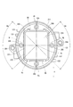
図2、図3および図7にコネクタユニット35の構成を示す。以下、モータ80の軸心Axと平行な方向を「軸方向」と記載する。また、モータ80の軸心Axに直交する方向を「径方向」と記載する。
コネクタユニット35は、ベース部350と、コネクタ部351と、コネクタ固定部354と、カバー固定部355と、各系統端子群とを有する。ベース部350は、カバー21の開口部211に対して内側に設けられている。コネクタ部351は2つのコネクタ351、352を有する。コネクタ351、352は、ベース部350から開口部211を通じてカバー21外に軸方向へ突き出している。
第1系統コネクタ351は、外部コネクタ161への接続間口356をもっている。接続間口356には、第1電源端子121、131、第1車両通信端子311および第1トルク信号端子331が配置されている。第2系統コネクタ352は、外部コネクタ162への接続間口357をもっている。接続間口357には、第2電源端子122、132、第2車両通信端子312および第2トルク信号端子332が配置されている。
コネクタ固定部354は、ベース部350から径方向外側に突き出すように形成されている。コネクタユニット35は、コネクタ固定部354を挿通するスクリュー157によりヒートシンク245に固定されている。カバー固定部355は、ベース部350のうちコネクタ部351に対して径方向外側に形成されている。カバー21は、スクリュー155によりカバー固定部355に固定されている。
ところで、例えば外部から制御ユニットへの入力信号を増やすこと等に応じてコネクタユニットの端子数を増やす場合には、増加分の端子を配置するスペースが余分に必要になり、コネクタユニットが大型化する。これにより、制御装置の径方向体格が大きくなって搭載性が低下するという問題がある。また、従来はシール部材が異形であったために組付け時に方向合わせが必要であった。本実施形態では、上記問題を解決するために下記構成が備わっている。
図7に示すように、ベース部350の軸方向シルエットは所定方向Xに長手状をなす形状である。2つのコネクタ351、352は、ベース部350の軸方向シルエットの長手方向に並ぶように配置されている。コネクタ固定部354は、ベース部350の軸方向シルエットの短軸線LSに対して回転軸心Axを中心に±45°の角度範囲Aa内でベース部350から径方向外側に突き出すように形成されている。コネクタ固定部354が角度範囲Aa内にあるということは、コネクタ固定部354がベース部350の軸方向シルエットの長軸線LLよりも短軸線LSに近づけて配置されるということである。本実施形態では、コネクタ固定部354は短軸線LSに重なるように設けられている。
ベース部350の軸方向シルエットは楕円形状である。また、ベース部350のうち接続間口356,357より外側に位置する外周部には、シール部材22用の楕円形状のシール溝358が形成されている。シール溝358には、円形のシール部材22が収められている。
軸方向視においてコネクタ部351が配置される領域をコネクタ配置領域Acとすると、コネクタ配置領域Acは所定方向Xに長手状をなす形状である。具体的には、コネクタ配置領域Acは、ベース部350の軸方向シルエットの長軸線LLに平行な一対の長辺SL、および、短軸線LSに平行な一対の短辺SSからなる矩形状である。
カバー固定部355は、一対の長辺SLとシール部材22との間に1つずつ、および、一対の短辺SSとシール部材22との間に1つずつ設けられている。4つのカバー固定部355は、長軸線LL上または短軸線LS上に配置されており、回転軸心Axまわりに等角度間隔に設けられている。
(効果)
以上説明したように、第1実施形態では、ベース部350の軸方向シルエットは所定方向Xに長手状をなす形状である。コネクタ固定部354は、ベース部350の軸方向シルエットの短軸線LSに対して回転軸心Axを中心に±45°の角度範囲Aa内でベース部350から径方向外側に突き出すように形成されている。
以上説明したように、第1実施形態では、ベース部350の軸方向シルエットは所定方向Xに長手状をなす形状である。コネクタ固定部354は、ベース部350の軸方向シルエットの短軸線LSに対して回転軸心Axを中心に±45°の角度範囲Aa内でベース部350から径方向外側に突き出すように形成されている。
このようにシール部材22に対して外側にコネクタ固定部354を配置することで、カバー21内を防水構造とすることができる。また、ベース部350を長手状とすることで端子配置スペースを増やしつつ、コネクタ固定部354をベース部350の軸方向シルエットの長軸線LLよりも短軸線LSに近づけて配置することで、コネクタユニット35全体を円形シルエット内に収めることができる。そのため、コネクタユニット35の端子数が増える場合であっても駆動装置1の径方向体格の大型化を抑制することができる。つまり、ベース部とコネクタ固定部の配置を最適化し、駆動装置1の径方向体格を小型化することで、搭載性の向上が実現した。
また、第1実施形態では、ベース部350の軸方向シルエットは楕円形状である。また、ベース部350の外周部には、シール部材22用の楕円形状のシール溝358が形成されている。これによりシール部材22に汎用のOリングを使用可能となり、組付け時の方向合わせが不要となる。
また、第1実施形態では、軸方向視においてコネクタ部351が配置される領域をコネクタ配置領域Acとすると、コネクタ配置領域Acは所定方向Xに長手状をなす形状である。これにより長手状のベース部350に対してコネクタ部351の配置が最適化され、コネクタ配置領域Acをできるだけ大きくすることができる。言い換えれば、カバー固定部355とコネクタ配置領域Acとの間の空間を削減することで、駆動装置1の径方向体格を小型化することができる。
また、第1実施形態では、コネクタ配置領域Acは、ベース部350の軸方向シルエットの長軸線LLに平行な一対の長辺SL、および、短軸線LSに平行な一対の短辺SSからなる矩形状である。これにより長手状のベース部350に対してコネクタ部351の配置が最適化され、コネクタ配置領域Acをできるだけ大きくすることができる。
また、第1実施形態では、カバー固定部355は、一対の長辺SLとシール部材22との間に1つずつ、および、一対の短辺SSとシール部材22との間に1つずつ設けられている。これにより各カバー固定部355を回転軸心Axまわりに略均等に配置することができる。そのため、シール部材22を均一に圧縮することで防水性を向上できる。また、カバー固定部355を長辺SLまたは短辺SSの中央に近づけることで、ベース部350をできるだけ小さく構成することができる。これにより駆動装置1の径方向体格を小型化することができる。
また、第1実施形態では、2つのコネクタ351、352は、ベース部350の軸方向シルエットの長手方向に並ぶように配置されている。これにより長手状のコネクタ配置領域Ac内に同じような大きさの2つのコネクタ351、352を無駄なく配置することができる。
[第2実施形態]
第2実施形態では、図8に示すように、ベース部360の軸方向シルエットは所定方向Xに長手状をなす形状であって、角が丸い矩形状である。シール溝368も同様に角が丸い矩形状である。このように、ベース部360は楕円形に限らず、矩形状であってもよい。上記以外について、第2実施形態は第1実施形態と同様の構成であり、第1実施形態と同様の効果を奏する。
第2実施形態では、図8に示すように、ベース部360の軸方向シルエットは所定方向Xに長手状をなす形状であって、角が丸い矩形状である。シール溝368も同様に角が丸い矩形状である。このように、ベース部360は楕円形に限らず、矩形状であってもよい。上記以外について、第2実施形態は第1実施形態と同様の構成であり、第1実施形態と同様の効果を奏する。
[第3実施形態]
第3実施形態では、図9に示すように、コネクタ部371は1つのコネクタ372を有する。コネクタ372は接続間口376をもっている。図9以降では各系統端子の図示を省略している。このように、コネクタ部371のコネクタ数は2つに限らず、1つであってもよい。上記以外について、第3実施形態は第1実施形態と同様の構成であり、第1実施形態と同様の効果を奏する。
第3実施形態では、図9に示すように、コネクタ部371は1つのコネクタ372を有する。コネクタ372は接続間口376をもっている。図9以降では各系統端子の図示を省略している。このように、コネクタ部371のコネクタ数は2つに限らず、1つであってもよい。上記以外について、第3実施形態は第1実施形態と同様の構成であり、第1実施形態と同様の効果を奏する。
[第4実施形態]
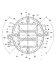
第4実施形態では、図10に示すように、コネクタ部381は3つのコネクタ382、383、384を有する。コネクタ382、383、384は接続間口386、387、388をもっており、ベース部350の軸方向シルエットの長手方向に並ぶように配置されている。このように、コネクタ部381のコネクタ数は2つに限らず、3つであってもよいし、4つ以上であってもよい。上記以外について、第4実施形態は第1実施形態と同様の構成であり、第1実施形態と同様の効果を奏する。
第4実施形態では、図10に示すように、コネクタ部381は3つのコネクタ382、383、384を有する。コネクタ382、383、384は接続間口386、387、388をもっており、ベース部350の軸方向シルエットの長手方向に並ぶように配置されている。このように、コネクタ部381のコネクタ数は2つに限らず、3つであってもよいし、4つ以上であってもよい。上記以外について、第4実施形態は第1実施形態と同様の構成であり、第1実施形態と同様の効果を奏する。
[第5実施形態]
第5実施形態では、図11に示すように、コネクタ部391は2つのコネクタ392、393を有する。コネクタ392、393は接続間口396、397をもっており、ベース部350の軸方向シルエットの短手方向に並ぶように配置されている。このように、コネクタ部391のコネクタ並び方向は長手方向に限らず、短手方向であってもよいし、他の方向であってもよい。上記以外について、第5実施形態は第1実施形態と同様の構成であり、第1実施形態と同様の効果を奏する。
第5実施形態では、図11に示すように、コネクタ部391は2つのコネクタ392、393を有する。コネクタ392、393は接続間口396、397をもっており、ベース部350の軸方向シルエットの短手方向に並ぶように配置されている。このように、コネクタ部391のコネクタ並び方向は長手方向に限らず、短手方向であってもよいし、他の方向であってもよい。上記以外について、第5実施形態は第1実施形態と同様の構成であり、第1実施形態と同様の効果を奏する。
[第6実施形態]
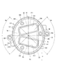
第6実施形態では、図12に示すように、コネクタ部501は2つのコネクタ502、503を有する。コネクタ502、503は接続間口506、507をもっている。コネクタ502はコネクタ503よりも大きく、また形状が異なる。コネクタ502はL字形状であり、コネクタ503は矩形状である。このように、コネクタ部501の各コネクタの大きさおよび形状が異なっていてもよい。上記以外について、第6実施形態は第1実施形態と同様の構成であり、第1実施形態と同様の効果を奏する。
第6実施形態では、図12に示すように、コネクタ部501は2つのコネクタ502、503を有する。コネクタ502、503は接続間口506、507をもっている。コネクタ502はコネクタ503よりも大きく、また形状が異なる。コネクタ502はL字形状であり、コネクタ503は矩形状である。このように、コネクタ部501の各コネクタの大きさおよび形状が異なっていてもよい。上記以外について、第6実施形態は第1実施形態と同様の構成であり、第1実施形態と同様の効果を奏する。
[第7実施形態]
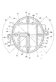
第7実施形態では、図13に示すように、コネクタ部511は2つのコネクタ512、513を有する。コネクタ512、513は接続間口516、517をもっている。コネクタ512、513は、短軸線LSを挟んで両側にそれぞれ配置されるとともに、長手方向が互いに交差するように配置されている。コネクタ配置領域Acは所定方向Xに長手状をなす形状であり、上底SUと下底SDと2つの脚SSからなる台形形状である。カバー固定部355は3つ設けられている。カバー固定部355は、一方の脚SSとシール溝358との間に1つ、他方の脚SSとシール溝358との間に1つ、および、下底SDとシール溝358との間に1つ配置されている。このように、カバー固定部355は4つに限らず、3つであってもよいし、5つ以上であってもよい。上記以外について、第7実施形態は第1実施形態と同様の構成であり、第1実施形態と同様の効果を奏する。
第7実施形態では、図13に示すように、コネクタ部511は2つのコネクタ512、513を有する。コネクタ512、513は接続間口516、517をもっている。コネクタ512、513は、短軸線LSを挟んで両側にそれぞれ配置されるとともに、長手方向が互いに交差するように配置されている。コネクタ配置領域Acは所定方向Xに長手状をなす形状であり、上底SUと下底SDと2つの脚SSからなる台形形状である。カバー固定部355は3つ設けられている。カバー固定部355は、一方の脚SSとシール溝358との間に1つ、他方の脚SSとシール溝358との間に1つ、および、下底SDとシール溝358との間に1つ配置されている。このように、カバー固定部355は4つに限らず、3つであってもよいし、5つ以上であってもよい。上記以外について、第7実施形態は第1実施形態と同様の構成であり、第1実施形態と同様の効果を奏する。
[他の実施形態]
他の実施形態では、コネクタ配置領域は、必ずしも所定方向に長手状をなす形状でなくてもよく、また、矩形状でなくてもよい。
他の実施形態では、コネクタ配置領域は、必ずしも所定方向に長手状をなす形状でなくてもよく、また、矩形状でなくてもよい。
他の実施形態では、モータは、二組の巻線組が同位相で配置されるものでもよい。また、モータの相の数は、三相に限らず四相以上でもよい。さらに駆動対象のモータは、交流ブラシレスモータに限らず、ブラシ付き直流モータとしてもよい。その場合、「電力変換器」としてHブリッジ回路を用いてもよい。また、他の実施形態では、駆動装置は、電動パワーステアリング装置に限らず、他のいかなる用途に適用されてもよい。
本開示は、実施形態に基づき記述された。しかしながら、本開示は当該実施形態および構造に限定されるものではない。本開示は、様々な変形例および均等の範囲内の変形をも包含する。また、様々な組み合わせおよび形態、さらには、それらに一要素のみ、それ以上、あるいはそれ以下、を含む他の組み合わせおよび形態も、本開示の範疇および思想範囲に入るものである。
Claims (6)
- モータ(80)と、
前記モータと同軸に配置され、前記モータの駆動を制御する制御ユニット(20)と、
前記制御ユニットを外部コネクタ(161、162)に接続するコネクタユニット(35)と、
前記コネクタユニットとは別部材からなり、前記制御ユニットを覆うカバー(21)と、
前記コネクタユニットと前記カバーとの間に設けられるシール部材(22)と、
を備え、
前記コネクタユニットは、ベース部(350、360)と、前記外部コネクタへの接続間口(356、357、376、386、387、388、396、397、506、507、516、517)をもつコネクタ部(351、371、381、391、501、511)と、前記ベース部を固定するコネクタ固定部(354)とを有し、
前記モータの回転軸心(Ax)に平行な方向を軸方向とすると、前記ベース部の軸方向シルエットは所定方向に長手状をなす形状であり、
前記コネクタ固定部は、前記ベース部の軸方向シルエットの短軸線(LS)に対して前記回転軸心を中心に±45°の角度範囲(Aa)内で前記ベース部から径方向外側に突き出すように形成されている駆動装置。 - 前記ベース部(350)の軸方向シルエットは楕円形状であり、
前記ベース部のうち前記接続間口より外側に位置する外周部には、前記シール部材用の楕円形状のシール溝(358)が形成されている請求項1に記載の駆動装置。 - 軸方向視において前記コネクタ部が配置される領域をコネクタ配置領域(Ac)とすると、
前記コネクタ配置領域は前記所定方向に長手状をなす形状である請求項1または2に記載の駆動装置。 - 前記コネクタ配置領域は、前記ベース部の軸方向シルエットの長軸線(LL)に平行な一対の長辺(SL)、および、前記短軸線に平行な一対の短辺(SS)からなる矩形状である請求項3に記載の駆動装置。
- 前記コネクタユニットは、前記シール部材に対する径方向内側で前記カバーを固定する複数のカバー固定部(355)をさらに有し、
前記カバー固定部は、前記一対の長辺と前記シール部材との間に1つずつ、および、前記一対の短辺と前記シール部材との間に1つずつ設けられている請求項4に記載の駆動装置。 - 前記コネクタ部は、前記ベース部の軸方向シルエットの長手方向に並ぶ複数のコネクタ(352、353、372、382、383、384、392、393、502、503、512、513)を有する請求項1~5のいずれか一項に記載の駆動装置。
Priority Applications (2)
| Application Number | Priority Date | Filing Date | Title |
|---|---|---|---|
| CN202080009194.5A CN113316881B (zh) | 2019-01-18 | 2020-01-15 | 驱动装置 |
| US17/376,422 US12065200B2 (en) | 2019-01-18 | 2021-07-15 | Drive device |
Applications Claiming Priority (2)
| Application Number | Priority Date | Filing Date | Title |
|---|---|---|---|
| JP2019-006524 | 2019-01-18 | ||
| JP2019006524A JP7172635B2 (ja) | 2019-01-18 | 2019-01-18 | 駆動装置 |
Related Child Applications (1)
| Application Number | Title | Priority Date | Filing Date |
|---|---|---|---|
| US17/376,422 Continuation US12065200B2 (en) | 2019-01-18 | 2021-07-15 | Drive device |
Publications (1)
| Publication Number | Publication Date |
|---|---|
| WO2020149293A1 true WO2020149293A1 (ja) | 2020-07-23 |
Family
ID=71614416
Family Applications (1)
| Application Number | Title | Priority Date | Filing Date |
|---|---|---|---|
| PCT/JP2020/001023 WO2020149293A1 (ja) | 2019-01-18 | 2020-01-15 | 駆動装置 |
Country Status (4)
| Country | Link |
|---|---|
| US (1) | US12065200B2 (ja) |
| JP (1) | JP7172635B2 (ja) |
| CN (1) | CN113316881B (ja) |
| WO (1) | WO2020149293A1 (ja) |
Cited By (2)
| Publication number | Priority date | Publication date | Assignee | Title |
|---|---|---|---|---|
| WO2024062849A1 (ja) * | 2022-09-21 | 2024-03-28 | 株式会社デンソー | 低速電動車両の駆動装置 |
| WO2024209577A1 (ja) * | 2023-04-05 | 2024-10-10 | 三菱電機株式会社 | 駆動装置および電動パワーステアリング装置 |
Citations (3)
| Publication number | Priority date | Publication date | Assignee | Title |
|---|---|---|---|---|
| JP2016048981A (ja) * | 2014-08-27 | 2016-04-07 | タイコエレクトロニクスジャパン合同会社 | モータ及びそれに用いる雌型コネクタ |
| JP2016103966A (ja) * | 2014-11-12 | 2016-06-02 | 日本電産株式会社 | モータ |
| JP2017108501A (ja) * | 2015-12-08 | 2017-06-15 | 株式会社デンソー | 駆動装置 |
Family Cites Families (9)
| Publication number | Priority date | Publication date | Assignee | Title |
|---|---|---|---|---|
| JPH10189156A (ja) * | 1996-12-20 | 1998-07-21 | Yazaki Corp | 可動コネクタ構造 |
| US8736039B2 (en) * | 2006-10-06 | 2014-05-27 | Taiwan Semiconductor Manufacturing Co., Ltd. | Stacked structures and methods of forming stacked structures |
| US8257110B2 (en) * | 2010-10-07 | 2012-09-04 | Tsmc Solid State Lighting Ltd. | Light emitting diode light bar module with electrical connectors formed by injection molding |
| JP5764459B2 (ja) | 2011-10-19 | 2015-08-19 | 株式会社デンソー | 駆動装置 |
| JP5853820B2 (ja) * | 2012-03-29 | 2016-02-09 | 株式会社デンソー | 駆動装置 |
| JP6172217B2 (ja) * | 2014-07-31 | 2017-08-02 | 株式会社デンソー | 駆動装置、および、これを用いた電動パワーステアリング装置 |
| DE102015221632A1 (de) * | 2014-11-12 | 2016-05-12 | Nidec Corporation | Motor |
| DE112016003891T5 (de) * | 2015-08-27 | 2018-05-09 | Nidec Corporation | Motor |
| JP6680053B2 (ja) * | 2016-04-06 | 2020-04-15 | 株式会社デンソー | 駆動装置、および、これを用いた電動パワーステアリング装置 |
-
2019
- 2019-01-18 JP JP2019006524A patent/JP7172635B2/ja active Active
-
2020
- 2020-01-15 CN CN202080009194.5A patent/CN113316881B/zh active Active
- 2020-01-15 WO PCT/JP2020/001023 patent/WO2020149293A1/ja active Application Filing
-
2021
- 2021-07-15 US US17/376,422 patent/US12065200B2/en active Active
Patent Citations (3)
| Publication number | Priority date | Publication date | Assignee | Title |
|---|---|---|---|---|
| JP2016048981A (ja) * | 2014-08-27 | 2016-04-07 | タイコエレクトロニクスジャパン合同会社 | モータ及びそれに用いる雌型コネクタ |
| JP2016103966A (ja) * | 2014-11-12 | 2016-06-02 | 日本電産株式会社 | モータ |
| JP2017108501A (ja) * | 2015-12-08 | 2017-06-15 | 株式会社デンソー | 駆動装置 |
Cited By (2)
| Publication number | Priority date | Publication date | Assignee | Title |
|---|---|---|---|---|
| WO2024062849A1 (ja) * | 2022-09-21 | 2024-03-28 | 株式会社デンソー | 低速電動車両の駆動装置 |
| WO2024209577A1 (ja) * | 2023-04-05 | 2024-10-10 | 三菱電機株式会社 | 駆動装置および電動パワーステアリング装置 |
Also Published As
| Publication number | Publication date |
|---|---|
| US20210339794A1 (en) | 2021-11-04 |
| CN113316881B (zh) | 2024-06-18 |
| JP2020115724A (ja) | 2020-07-30 |
| JP7172635B2 (ja) | 2022-11-16 |
| CN113316881A (zh) | 2021-08-27 |
| US12065200B2 (en) | 2024-08-20 |
Similar Documents
| Publication | Publication Date | Title |
|---|---|---|
| JP7124401B2 (ja) | 駆動装置 | |
| JP6680054B2 (ja) | 駆動装置、および、これを用いた電動パワーステアリング装置 | |
| JP7124400B2 (ja) | 駆動装置 | |
| JP6907992B2 (ja) | 駆動装置および駆動ユニット | |
| EP3843250A1 (en) | Electric power steering device | |
| US11565741B2 (en) | Electric power steering device | |
| JP7244216B2 (ja) | 回転電機制御装置 | |
| JP2017189033A (ja) | 駆動装置、および、これを用いた電動パワーステアリング装置 | |
| JP7120216B2 (ja) | モータおよび電動パワーステアリング装置 | |
| US11081995B2 (en) | Motor control device | |
| US20210339794A1 (en) | Drive device | |
| US11801887B2 (en) | Drive device | |
| JP7211288B2 (ja) | 駆動装置 | |
| JP2020108317A (ja) | 電力変換装置、駆動装置およびパワーステアリング装置 | |
| JP2008290675A (ja) | 電動パワーステアリング装置 | |
| WO2022196458A1 (ja) | 駆動装置 | |
| WO2022030423A1 (ja) | 複数モータ駆動システム | |
| JPWO2012098703A1 (ja) | 電動パワーステアリング用電動モータ装置及び電動パワーステアリング装置 |
Legal Events
| Date | Code | Title | Description |
|---|---|---|---|
| 121 | Ep: the epo has been informed by wipo that ep was designated in this application |
Ref document number: 20742055 Country of ref document: EP Kind code of ref document: A1 |
|
| NENP | Non-entry into the national phase |
Ref country code: DE |
|
| 122 | Ep: pct application non-entry in european phase |
Ref document number: 20742055 Country of ref document: EP Kind code of ref document: A1 |