WO2020149290A1 - スパイクベース、スパイク金具、スパイクソールおよびその製造方法 - Google Patents
スパイクベース、スパイク金具、スパイクソールおよびその製造方法 Download PDFInfo
- Publication number
- WO2020149290A1 WO2020149290A1 PCT/JP2020/001012 JP2020001012W WO2020149290A1 WO 2020149290 A1 WO2020149290 A1 WO 2020149290A1 JP 2020001012 W JP2020001012 W JP 2020001012W WO 2020149290 A1 WO2020149290 A1 WO 2020149290A1
- Authority
- WO
- WIPO (PCT)
- Prior art keywords
- spike
- sole
- sole body
- fitting
- concave surface
- Prior art date
- Legal status (The legal status is an assumption and is not a legal conclusion. Google has not performed a legal analysis and makes no representation as to the accuracy of the status listed.)
- Ceased
Links
Images





Classifications
-
- A—HUMAN NECESSITIES
- A43—FOOTWEAR
- A43B—CHARACTERISTIC FEATURES OF FOOTWEAR; PARTS OF FOOTWEAR
- A43B13/00—Soles; Sole-and-heel integral units
- A43B13/14—Soles; Sole-and-heel integral units characterised by the constructive form
- A43B13/16—Pieced soles
-
- A—HUMAN NECESSITIES
- A43—FOOTWEAR
- A43B—CHARACTERISTIC FEATURES OF FOOTWEAR; PARTS OF FOOTWEAR
- A43B13/00—Soles; Sole-and-heel integral units
- A43B13/14—Soles; Sole-and-heel integral units characterised by the constructive form
- A43B13/22—Soles made slip-preventing or wear-resisting, e.g. by impregnation or spreading a wear-resisting layer
- A43B13/24—Soles made slip-preventing or wear-resisting, e.g. by impregnation or spreading a wear-resisting layer by use of insertions
- A43B13/26—Soles made slip-preventing or wear-resisting, e.g. by impregnation or spreading a wear-resisting layer by use of insertions projecting beyond the sole surface
-
- A—HUMAN NECESSITIES
- A43—FOOTWEAR
- A43C—FASTENINGS OR ATTACHMENTS OF FOOTWEAR; LACES IN GENERAL
- A43C15/00—Non-skid devices or attachments
- A43C15/02—Non-skid devices or attachments attached to the sole
Definitions
- the present invention relates to a spike base, a spike metal fitting, a spike sole, and a manufacturing method thereof.
- spikes for land use have a basic structure with a metal base embedded in hard resin and pins protruding downward.
- the metal base secures the pin holding force.
- the pin pierces the road surface and transmits the athlete's power to the road surface without loss. Therefore, such a basic structure necessarily requires a base with high rigidity.
- Patent Document 1 As a spiked sole that is expected to have a lightweight and smooth bending performance while maintaining a grip required for competitions, etc., a sole provided with a honeycomb-shaped spike has been proposed (Patent Document 1). ..
- an object of the present invention is to provide a spike sole capable of further improving the bending performance of the resin sole and enhancing the joining force between the resin sole and the spike fitting, and a method for manufacturing the spike sole.
- the spike sole is integrally formed with a resin-made sole body 1, and a tip 11 projects downward from a top surface 1F of the sole body 1 and is defined by the tip 11 and the top surface 1F of the sole body 1.
- a resin spike base 10 having a concave surface 12 The spike base 10 has a convex surface 20 that is joined to the concave surface 12 in a state of being in close contact with the concave surface 12, and extends from the metallic adherend 21 forming the convex surface 20 to the concave surface 12 of the spike base 10.
- a metal spike fitting 2 made of metal which has a spike portion 22 that projects downward from the tip 11 of the spike base 10 and that is continuous with the adhered portion 21 made of metal.
- the spike base of the present invention is formed integrally with the sole body 1 made of resin, and the tip 11 projects downward from the top surface 1F of the sole body 1, and the tip 11 and the top surface 1F of the sole body 1 are joined together. It has a defined concave surface 12.
- the spike metal fitting of the present invention has a convex surface 20 that is joined to the concave surface 12 of the sole body made of resin in a state of being in close contact with the concave surface 12, and from the metal-made adhered portion 21 forming the convex surface 20 to the concave surface 12.
- a spike portion 22 is formed along the bottom of the spike portion 22 and extends downward and is integrally connected to the adhered portion 21 made of metal.
- the spike base 10 has the tip 11 protruding downward from the concave surface 12 that is a part of the top surface 1F. Therefore, the protruding tip 11 increases the surface area of the concave surface 12 of the spike base 10. Therefore, a compact joint surface can be obtained as compared with the case of a normal flat spike base.
- the adhered portion 21 of the spike fitting 2 has a convex surface 20 along the concave surface 12. Therefore, the convex surface 20 is more compact and has a larger surface area than the case where the convex surface 20 is bonded to a normal flat spike base.
- the joining force between them is also increased.
- the concave surface 12 and the convex surface 20 have a small projected area in the sole body 1, the bending performance of the resin-made sole body 1 will be improved.
- the tip 11 of the spike base 10 projects downward from the top surface 1F of the sole body 1, and the tip 11 will also pierce the ground immediately after the spike portion 22 pierces the ground. Therefore, the sole will have a greater grip on the ground.
- the spike sole preferably further includes a tightening portion that tightens the spike base 10 and the adhered portion 21 of the spike fitting 2. More preferably, the tightening portion is formed by a rivet 5 that penetrates the top surface 1F of the sole body 1 and the adhered portion 21 of the spike portion.
- the convex surface 20 of the spike metal fitting 2 is adhered to the concave surface 12 of the spike base by the bonding force of the resin, and the spike metal fitting 2 is further fastened to the sole body 1 by a fastening portion such as a rivet, High bond strength can be obtained.
- the method of the present invention is a method for manufacturing a spike sole in which a spike metal fitting 2 is fixed to a resin-made sole body 1.
- a step of bringing the adhered portion 21 of the spike metal fitting 2 into close contact with the mounting surface while the mounting surface of the sole body 1 to which the spike metal fitting 2 is fixed is melted; Solidifying the mounting surface to bond the adherend 21 to the mounting surface; After the connection, the sole body and the spike fitting 2 are fastened to each other by a fastening portion.
- the adhered portion 21 of the spike fitting 2 comes into close contact with the mounting surface of the sole body 1 in a melted state. Therefore, the adherend 21 is adhered to the mounting surface by the strong bonding force of the resin. Further, the sole body 1 and the spike fitting 2 are fastened to each other by the fastening portion, and the coupling force of the adhered portion 21 to the mounting surface is increased.
- the fastening portion is formed of a rivet, and in the fastening portion step, the rivet penetrates the attached portion 21 of the spike fitting 2 and the mounting surface of the sole body 1. Then, the adhered portion 21 and the sole body 1 are tightened. As described above, when the sole body 1 and the spike fitting 2 are fastened with the rivets, the fastening process can be performed easily and reliably.
- mass production of spike soles is easy.
- the step of closely contacting The adhered portion 21 is pressed against and closely adhered to the mounting surface in a state where the mounting surface of the sole body 1 that has been molded in advance is melted.
- individual spike fittings 2 can be attached to the spike base after molding, and a spike sole according to the taste of each wearer can be obtained.
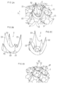
- FIG. 1 is a schematic perspective view of a spike sole showing a first embodiment of the present invention.
- 2A to 2D are enlarged views according to the first embodiment.
- FIG. 2A is a partially enlarged perspective view of a sole body
- FIGS. 2B and 2C are enlarged perspective views of spike fittings
- FIG. 2D is a partially enlarged perspective view of a spike base.
- Is. 3A, 3B and 3C are enlarged sectional views showing an example of the manufacturing method
- FIGS. 3D and 3E are sectional views of the spike sole.
- 4A is an enlarged perspective view showing a second embodiment of the spike fitting
- FIG. 4B is a partially enlarged perspective view of the spike base.
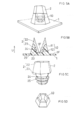
- 5A to 5D are enlarged views according to the third embodiment.
- FIG. 5A is a partial perspective view of the spike sole
- FIG. 5B is the same sectional view
- FIG. 5C is a perspective view of the same metal fitting
- FIG. 5D is a spike base.
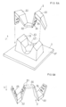
- FIG. 6A and 6B are enlarged views according to the fourth embodiment
- FIG. 6A is a perspective view of a fitting and a spike base
- FIG. 6B is a perspective view of a spike fitting
- 7A to 7D are enlarged views according to still another embodiment
- FIG. 7A is a sectional perspective view
- FIGS. 7B, 7C, and 7D are sectional views
- 8A and 8B are cross-sectional views according to still another embodiment.
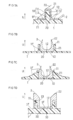
- 9A to 9D are enlarged cross-sectional views of a molding process showing another example of the method for manufacturing the spike sole.
- 10A to 10D are enlarged cross-sectional views showing an example of a fastening step in the manufacturing method.
- the adhered portion 21 defines a through hole 23 or an engagement recess 24 into which the resin of the spike base 10 projects and engages from the concave surface 12.
- the resin of the spike base 10 will be engaged with the through hole 23 or the engagement recess 24, and the coupling force between the spike fitting 2 and the spike base 10 will be increased.
- the adhered portion 21 of the spike fitting 2 is pressed against the spike base 10, the melted resin escapes into the through hole 23 and the engaging recess 24. Therefore, the concave surface 12 of the spike base 10 and the convex surface 20 of the adherend 21 are likely to come into close contact with each other, and the bonding force will be increased.
- the convex surface 20 of the adhered portion 21 is provided with an engaging convex portion 25 with which the resin of the spike base 10 is engaged.
- the engagement of the engagement protrusions 25 will increase the binding force.
- the adhered portion 21 is formed in a bowl shape.
- the bowl-shaped adhered portion 21 increases the area of contact with the concave surface 12 of the sole body 1.
- the projected area of the sole body 1 is reduced, and smooth bending performance is exhibited.
- the spike portion 22 is formed of a spinous process connected to the bowl-shaped adherend 21, and more preferably, the spinous process is a mountain shape tapered toward the tip.
- a mountain-shaped spinous process will exhibit a sufficient engaging force even if the depth of penetration into the ground is smaller than that of a round rod-shaped pin. Therefore, the resistance when the spike portion 22 comes out from the ground is small, and the loss of running force will be small.
- the adhered portion 21 has a rectangular tubular shape.
- the rectangular tube-shaped adherend 21 may be difficult to rotate around the vertical axis.
- the tip 11 of the spike base 10 forms a wall-shaped wall portion
- the spike portion 22 is formed so as to cover the wall portion. Since the spike portion 22 that covers the wall portion is thick, it is easy to exert the engaging force even on soft ground.
- the adhered portion 21 is seamlessly and integrally connected to the spike portion 22.
- the present manufacturing method is a method for manufacturing a spike sole in which the spike metal fitting 2 is fixed to the resin sole body 1, A step of molding the sole body 1, A step of generating the spike fitting 2; Pressing the adhered portion 21 of the spike fitting 2 against the mounting surface in a state where the mounting surface of the sole body 1 to which the spike fitting 2 is fixed is melted after the sole body 1 is molded; The mounting surface is solidified, and the adherend 21 is joined to the concave surface 12.
- the spike sole can be manufactured by the following method.
- a more specific manufacturing method is a method of manufacturing a spike sole in which the spike metal fitting 2 is fixed to a resin-made sole body 1, A step of molding the sole body 1, A step of generating the spike fitting 2; Pressing the adherend 21 of the spike fitting 2 against the concave surface 12 in a state where the concave surface 12 of the sole body 1 is melted after the sole body 1 is molded; The concave surface 12 is solidified, and the adherend 21 is joined to the concave surface 12.
- FIG. 1 shows a spike sole.
- the spike sole shown in FIG. 1 is, for example, a spike sole for athletics.
- the spike sole includes a hard sole body 1 containing a non-foamed resin component, and a spike fitting 2 fixed to the sole body 1.
- the sole body 1 may be made of, for example, FRP (fiber reinforced plastic) reinforced with reinforcing fibers.
- the sole body 1 may be formed of a laminated body in which a plurality of prepreg sheets and a plurality of adhesive films are laminated. Further, the sole body 1 may be formed of a laminated body in which thin prepreg sheets cut in a tape shape are laminated so that the fiber directions are random.
- the sole body 1 may be formed by molding a thermoplastic resin plate containing reinforcing fibers. Such a molding method is described in PCT/JP16/88491, which is hereby incorporated by reference in its entirety.
- thermoplastic resin for example, thermoplastic polyamide resin, urethane resin, epoxy resin, polypropylene resin or the like can be used.
- the resin component may be used alone or in combination of two or more.
- reinforcing fiber for example, carbon fiber, glass fiber, aramid fiber, boron fiber or the like can be used.
- the sole body 1 is formed with a plurality of protruding tips 11.
- the tip 11 projects from the top surface 1F of the sole body 1 toward the ground below U (upper in the figure).
- the tip 11 and the top surface 1F define a spike base 10 having a concave surface 12.
- a spike fitting 2 is fixed to at least one of the spike bases 10.
- the spike fitting 2 has a convex surface 20 that is bonded to the concave surface 12 of the spike base 10 and is joined to the concave surface 12.
- the convex surface 20 of FIG. 3C is formed on a bowl-shaped adhered portion 21, for example.
- the spike metal fitting 2 is made of metal and has the adhered portion 21 and a plurality of spike portions 22 that are seamlessly connected to the adhered portion 21.
- Each of the spike portions 22 projects from the adhered portion 21 along the concave surface 12 of the spike base 10 and downwardly from the tip 11 of the spike base 10 (upward in the figure).
- three or more spike portions 22 of FIG. 2B are provided.
- the three spikes 22 may be spaced apart from each other in the circumferential direction of the bowl-shaped adherend 21.
- the spike portion 22 may be formed of a spinous process continuous with the adherend 21. That is, the spike portion 22 may have a mountain shape that tapers inward.
- the convex surface 20 of the adherend 21 may be provided with a convex portion 25 with which the resin of the spike base 10 is engaged.
- the concave surface 12 of the spike base 10 is formed with a concave portion that engages with the convex portion 25.
- the adherend 21 may be provided with a through hole 23.
- the resin of the spike base 10 projects from the concave surface 12 and engages with the through hole 23.
- FIG. 1 shows the sole body 1 of FIG. 1 primarily molded, and the spike fitting 2 of FIGS. 2B and 2C is produced.
- FIG. 2D shows the top surface 1F of the primary molded spike sole, and in this state, the concave surface 12 is not provided with a concave portion that engages with the convex portion 25 (FIG. 3C).
- the spike metal fitting 2 is heated to raise the temperature.
- the temperature of the spike metal fitting 2 is set to a temperature above the melting temperature of the resin of the sole body 1.
- the adhered portion 21 of the spike fitting 2 is pressed against the concave surface 12 in a state in which the concave surface 12 of the sole body 1 is melted by the spiked metal fitting 2 that has been heated. Then, the concave surface 12 is solidified and the adhered portion 21 is joined to the concave surface 12.
- the convex portion 25 formed on the convex surface 20 enters the concave surface 12 as shown in FIG. 3C while biting into the surface of the concave surface 12. It should be noted that the convex portion 25 formed on the convex surface 20 of the adhered portion 21 is exaggeratedly shown in a large size in FIGS. 3A to 3C, and it is preferable that the convex portion 25 is actually small.
- the convex surface 20 of the adhered portion 21 may be formed as a rough surface without providing the convex portion 25 on the adhered portion 21. If the convex surface 20 is rough, the binding force will be higher than that of a smooth surface.
- a solvent may be applied to the surface of the concave surface 12.
- the surface of the concave surface 12 may be melted with hot air or a heat source.
- the resin near the concave surface 12 is pressed.
- the volume of the pressed resin escapes from the through hole 23 as shown in FIG. 3D or FIG. 3E, so that the convex surface 20 and the concave surface 12 of the adherend 21 are likely to adhere to each other without a gap. In that case, high engagement force can be expected.
- the plurality of spike-shaped spike portions 22 that are spaced apart from each other in the circumferential direction of the convex surface 20 easily stabilize the engaging force with respect to the ground. For example, it may be easy to accelerate from a stationary state by exerting a high engaging force not only in the traveling direction but also in the lateral direction.
- 4A to 7D show another embodiment.
- a structure different from that of the first embodiment will be mainly described.
- FIG. 4A and 4B show the second embodiment.
- the convex surface 20 of the spike fitting 2 is provided with both an engaging concave portion 24 and an engaging convex portion 25.
- the engaging recess 24 is for the resin to escape like the through hole 23, and the adhered portion 21 is engaged with the resin that has entered the engaging recess 24.
- the spike portion 22 of this example may include two spinous processes and two knife-shaped processes.
- the spike base 10 in FIG. 4B is shown in a state before the spike fitting 2 is joined (before melting).
- the adhered portion 21 has a rectangular tubular shape.
- the spike portion 22 is provided so as to cover the tip 11 of the spike base 10. Further, the engagement concave portion 24 and the engagement convex portion 25 are connected in a loop shape in the circumferential direction of the rectangular tube.
- FIG. 6A and 6B show the fourth embodiment.
- the tip 11 of the spike base 10 shown in FIG. 6A forms a wall-shaped wall portion.
- the spike portion 22 of FIG. 6A is fitted into the tip 11 so as to cover the tip 11 which is a wall portion.
- the adhered portion 21 in FIG. 6B may be provided with an engagement concave portion 24 and an engagement convex portion 25.
- the convex surface 20 that fits into the concave surface 12 of FIG. 6A may be formed in a trapezoidal cross section.
- FIG. 7A shows Example 5.
- the wall-shaped tip 11 is covered with the adherend 21.
- the spike base 10 has two concave surfaces 12.
- Example 6 is shown in FIGS. 7B and 7C.
- the adherend 21 may be along the concave surface 12 of the spike base 10 in part, and may not be along the concave surface 12 in the remaining part.
- the top surface 1F of the sole body 1 is the lower surface of the sole body 1 and is the surface to which the convex surface 20 of the adherend 21 is joined. Although the sole body 1 may be thicker than other portions on the top surface 1F, it may be thin as shown in FIG. 7C.
- FIG. 7D shows Example 7. As shown in this figure, the spike fitting 2 may be fitted onto the tip 11 of the spike base 10.
- Example 8 is shown in FIG. 8A and FIG. 8B.
- the metal adherend 21 may not be partially along the concave surface 12 of the spike base 10.
- the spike portion 22 may be formed by, for example, a single pin that is pointed toward the tip of the tapered shape, and does not have to follow the concave surface 12 at all.
- FIGS. 9 and 10 show a spike sole of Example 9 and a method for manufacturing the spike sole.
- FIG.10(d) is a partial expanded sectional view of a spike sole. As shown in this figure, also in the present example, as in the case of the first embodiment, the spike base 10 made of resin is covered with the metal fitting 2 made of metal.
- the spike base 10 is integrally formed with the resin sole body 1 (FIG. 1).
- the spike base 10 has a concave surface 12 defined by the distal end 11 and the top surface 1F of the sole body 1 with a tip 11 protruding downward from the top surface 1F of the sole body 1 toward the lower side U (above the paper surface).
- the spike fitting 2 has an adhered portion 21 and a spike portion 22 that is continuous with the adhered portion 21.
- the adhered portion 21 has a convex surface 20 that is joined to the concave surface 12 while being in close contact with the concave surface 12 of the spike base 10.
- the spike portion 22 projects from the adhered portion 21 along the concave surface 12 of the spike base 10 and further toward the lower side U than the tip 11 of the spike base 10.
- the present example of FIG. 10D further includes a tightening portion that tightens the spike base 10 and the adhered portion 21 of the spike fitting 2.
- the tightening portion is formed by, for example, a rivet 5 that penetrates the top surface 1F of the sole body 1 and the adhered portion 21 of the spike portion 22.
- a rivet 5 in addition to a well-known blind rivet, an eyelet-like hollow rivet or a solid rivet can be adopted.
- the blind rivet 5 of FIG. 10D fastens the spike base 10 and the adhered portion 21 between the head portion 51 that engages with the sole body 1 and the deformed portion 52 that engages with the adhered portion 21. To do.
- first and second molds 61 and 62 are prepared prior to manufacturing.
- the first die 61 is provided with a loading portion 63 for loading the spike fitting 2.
- the attached portion 21 of the spike fitting 2 is provided with a first through hole 2H.
- the first through hole 2H fits into the protrusion 64 at the tip of the loading portion 63 of the first mold 61.
- the spike metal fitting 2 is loaded into the first mold 61 so that the first through hole 2H fits into the protrusion 64 of the first mold 61.
- the resin material 19 forming the sole body 1 is supplied (disposed) between the first mold 61 and the second mold 62.
- the resin material 19 is heated in the molds 61 and 62.
- the molds 61 and 62 are clamped, and the resin material 19 (FIG. 9A) conforms to the shape of the cavity 65 of the molds 61 and 62. Be in shape.
- the concave surface 12 that is in close contact with the convex surface 20 of the adhered portion 21 of the spike fitting 2 is formed on the spike base 10.
- the spike base 10 is formed with a second through hole 1H that matches the protrusion 64 of the loading portion 63.
- the position of the second through hole 1H matches the position of the first through hole 2H.
- the molds 61 and 62 are opened, and the spike metal fitting 2 is integrally molded with the spike base 10. As shown in FIG. Is obtained. At this time, the mounting surface 12 is solidified and the adherend 21 is joined in a state of being in close contact with the mounting surface 12.
- the sole body 1 and the spike metal fitting 2 are fastened to each other by rivets, as described below.
- the blind rivet 5A before being deformed is inserted into the second through hole 1H of the sole body 1 and the first through hole 2H of the spike fitting 2.
- the blind rivet 5A is composed of a hollow rivet 5 and a mandrel 53.
- the hollow rivet 5 is deformed as shown in FIG. 10C.
- the sole body 1 and the spike fitting 2 are fastened between the head portion 51 of the hollow rivet 5 and the deformation portion 52 at the tip on the opposite side. That is, the rivet 5 penetrates the adhered portion 21 of the spike fitting 2 and the mounting surface 12 of the sole body 1 to tighten the adhered portion 21 and the sole body 1.
- the intermediate product 3 of FIG. 9(d) may use the sole body 1 and the spike metal fitting 2 which are individually molded in advance as in the first embodiment, instead of the insert molding.
- the spike metal fitting 2 is pressed and brought into close contact with the mounting surface 12 of the preformed sole body 1.
- spike fittings may be provided on the rear foot in addition to the front foot.
- the number of spike fittings may be only one or may be plural. Accordingly, such changes and modifications are intended to be within the scope of the invention as defined by the appended claims.
- the spike sole of the present invention can be used not only for athletics but also for other spike soles such as football, baseball spikes and anti-slip shoes.
Landscapes
- Footwear And Its Accessory, Manufacturing Method And Apparatuses (AREA)
Abstract
本スパイクソールは樹脂製のソール本体1に一体に形成され、ソール本体1の天面1Fから下方に向かって先端11が突出し先端11とソール本体1の天面1Fとで定義される凹面12を有する樹脂製のスパイクベース10と、スパイクベース10の凹面12に密着した状態で凹面12に結合される凸面20を有し、凸面20を形成する金属製の被着部21からスパイクベース10の凹面12に沿って、かつ、スパイクベース10の先端11よりも下方に向かって突出し金属製の被着部21に一体に連なるスパイク部22を有する金属製のスパイク金具2とを備える。
Description
本発明はスパイクベース、スパイク金具、スパイクソールおよびその製造方法に関する。
例えば、陸上用などのスパイクは基本的な構造として、硬質樹脂の中に埋め込まれる金属ベースと下に突出するピンとを備える。前記金属ベースはピンの保持力を確保する。ピンは路面に刺さることでロスなくアスリートの力を路面に伝える。したがって、かかる基本構造には剛性の大きいベースが必ず必要となる。
しかし、スパイクソールのスムースな屈曲を考えた場合、剛性の大きい金属ベースの存在はスパイクソールのスムースな屈曲性能を妨げる要因となる。さらに、この金属ベース周辺のソールの強度を高めるためには金属ベース周辺の樹脂の量を増やす必要がある。これにより、屈曲性能はさらに低下し、また、スパイクソールの重量が増加し易い。
そこで、競技等に必要なグリップ性を維持しつつ、軽量で、かつ、スムースな屈曲性能が期待できるスパイクソールとして、近年、ハニカム状のスパイクを備えたソールが提案されている(特許文献1)。
しかし、前記先行技術ではスパイク金具の地面に刺さるスパイク部よりも、樹脂ソールに接合される部位が大きくなり、前記屈曲性能の向上が今一つ十分ではない場合がある。
また、樹脂ソールに接着されるスパイク金具の面が小さく、十分な接合力が得られない場合がある。
したがって、本発明の目的は、樹脂ソールの屈曲性能を更に向上できると共に、樹脂ソールとスパイク金具の接合力を高めることができるスパイクソールおよびその製造方法を提供することである。
また、樹脂ソールに接着されるスパイク金具の面が小さく、十分な接合力が得られない場合がある。
したがって、本発明の目的は、樹脂ソールの屈曲性能を更に向上できると共に、樹脂ソールとスパイク金具の接合力を高めることができるスパイクソールおよびその製造方法を提供することである。
本スパイクソールは、樹脂製のソール本体1に一体に形成され、前記ソール本体1の天面1Fから下方に向かって先端11が突出し前記先端11と前記ソール本体1の天面1Fとで定義される凹面12を有する樹脂製のスパイクベース10と、
前記スパイクベース10の前記凹面12に密着した状態で前記凹面12に結合される凸面20を有し、前記凸面20を形成する金属製の被着部21から前記スパイクベース10の前記凹面12に沿って、かつ、前記スパイクベース10の前記先端11よりも前記下方に向かって突出し前記金属製の前記被着部21に一体に連なるスパイク部22を有する金属製のスパイク金具2とを備える。
前記スパイクベース10の前記凹面12に密着した状態で前記凹面12に結合される凸面20を有し、前記凸面20を形成する金属製の被着部21から前記スパイクベース10の前記凹面12に沿って、かつ、前記スパイクベース10の前記先端11よりも前記下方に向かって突出し前記金属製の前記被着部21に一体に連なるスパイク部22を有する金属製のスパイク金具2とを備える。
本発明のスパイクベースは、樹脂製のソール本体1に一体に形成され、前記ソール本体1の天面1Fから下方に向かって先端11が突出し前記先端11と前記ソール本体1の天面1Fとで定義される凹面12を有する。
本発明のスパイク金具は、樹脂製のソール本体の凹面12に密着した状態で前記凹面12に結合される凸面20を有し、前記凸面20を形成する金属製の被着部21から前記凹面12に沿って、かつ、下方に向かって突出し前記金属製の前記被着部21に一体に連なるスパイク部22を有する。
本発明によれば、スパイクベース10は天面1Fの一部である凹面12から下方に向かって突出する先端11を有する。したがって、前記突出した先端11はスパイクベース10の凹面12の表面積を大きくする。そのため、通常の平坦なスパイクベースの場合に比べ、コンパクトな接合面が得られる。
一方、スパイク金具2の被着部21は前記凹面12に沿った凸面20を有する。したがって、前記凸面20は通常の平坦なスパイクベースに接合する場合よりもコンパクトで、かつ、表面積が大きい。
このように互いに接合されるスパイクベース10とスパイク金具2の凸面20とは互いに大きな表面積で接合されているため、その結合力も大きくなる。一方、前記凹面12と凸面20はソール本体1における投影面積が小さくなるから、樹脂製のソール本体1の屈曲性能は向上するであろう。
更に、スパイクベース10の先端11は、ソール本体1の天面1Fから下方に向かって突出しており、前記スパイク部22が地中に刺さった直後、前記先端11も地面に刺さるであろう。したがって、ソールが地面を掴む力が大きくなるであろう。
本スパイクソールにおいて、好ましくは、前記スパイクベース10と前記スパイク金具2の被着部21とを締め付ける締付部を更に備える。より好ましくは、前記締付部は前記ソール本体1の天面1Fおよび前記スパイク部の被着部21を貫通するリベット5で形成されている。
これらの場合、スパイクベースの凹面12にスパイク金具2の凸面20が樹脂の結合力で被着している上に、更に、リベット等の締結部でスパイク金具2がソール本体1に締結されて、高い結合力が得られる。
これらの場合、スパイクベースの凹面12にスパイク金具2の凸面20が樹脂の結合力で被着している上に、更に、リベット等の締結部でスパイク金具2がソール本体1に締結されて、高い結合力が得られる。
一方、本発明方法は、1つの局面において、樹脂製のソール本体1にスパイク金具2が固着されたスパイクソールの製造方法であって、
前記スパイク金具2が固着される前記ソール本体1の装着面が融解した状態で前記スパイク金具2の被着部21が前記装着面に密着する工程と、
前記装着面が固化して前記被着部21が前記装着面に結合される工程と、
前記結合後に、前記ソール本体と前記スパイク金具2とが締結部により互いに締結される工程とを備える。
前記スパイク金具2が固着される前記ソール本体1の装着面が融解した状態で前記スパイク金具2の被着部21が前記装着面に密着する工程と、
前記装着面が固化して前記被着部21が前記装着面に結合される工程と、
前記結合後に、前記ソール本体と前記スパイク金具2とが締結部により互いに締結される工程とを備える。
この1つの局面によれば、ソール本体1の装着面が融解した状態でスパイク金具2の被着部21が前記装着面に密着する。そのため、樹脂の強い結合力で被着部21が装着面に被着される。
更に、ソール本体1とスパイク金具2とが締結部により互いに締結され、前記装着面に対する被着部21の結合力が高まる。
更に、ソール本体1とスパイク金具2とが締結部により互いに締結され、前記装着面に対する被着部21の結合力が高まる。
前記1つの局面において、好ましくは、前記締結部はリベットで構成され、前記締結部工程において、前記リベットが前記スパイク金具2の前記被着部21と前記ソール本体1の装着面とを貫通して、前記被着部21とソール本体1とを締め付ける。
このように、リベットでソール本体1とスパイク金具2とを締め付ける場合、締結工程を容易かつ確実に行うことができる。
このように、リベットでソール本体1とスパイク金具2とを締め付ける場合、締結工程を容易かつ確実に行うことができる。
好ましくは、前記密着する工程は、
前記スパイク金具2をソール本体1の金型内に装填する工程と、
前記金型内に樹脂を供給して前記スパイク金具2と前記ソール本体1とを一体に成形する工程とを備える。
このようにインサート成形をした場合、スパイクソールを量産し易い。
前記スパイク金具2をソール本体1の金型内に装填する工程と、
前記金型内に樹脂を供給して前記スパイク金具2と前記ソール本体1とを一体に成形する工程とを備える。
このようにインサート成形をした場合、スパイクソールを量産し易い。
好ましくは、前記密着する工程は、
予め成形された前記ソール本体1の前記装着面を融解させた状態で前記被着部21を前記装着面に押し付けて密着させる。
この場合、成型後のスパイクベースに個別のスパイク金具2を装着でき、個々の着用者の好みに応じたスパイクソールを得ることができる。
予め成形された前記ソール本体1の前記装着面を融解させた状態で前記被着部21を前記装着面に押し付けて密着させる。
この場合、成型後のスパイクベースに個別のスパイク金具2を装着でき、個々の着用者の好みに応じたスパイクソールを得ることができる。
本スパイクソールにおいて、好ましくは、前記被着部21は前記凹面12から前記スパイクベース10の樹脂が突出して係合する貫通孔23または係合凹部24を定義する。
この場合、貫通孔23または係合凹部24にスパイクベース10の樹脂が係合して、スパイク金具2とスパイクベース10との結合力が増大するだろう。
また、スパイクベース10にスパイク金具2の被着部21を押し付けた際に、融解していた樹脂が前記貫通孔23や係合凹部24に逃げる。そのため、スパイクベース10の凹面12と被着部21の凸面20とが密着し易く、結合力が増大するだろう。
この場合、貫通孔23または係合凹部24にスパイクベース10の樹脂が係合して、スパイク金具2とスパイクベース10との結合力が増大するだろう。
また、スパイクベース10にスパイク金具2の被着部21を押し付けた際に、融解していた樹脂が前記貫通孔23や係合凹部24に逃げる。そのため、スパイクベース10の凹面12と被着部21の凸面20とが密着し易く、結合力が増大するだろう。
好ましくは、前記被着部21の前記凸面20には前記スパイクベース10の樹脂が係合する係合凸部25が設けられている。
この場合、係合凸部25の係合により、結合力が増大するだろう。
この場合、係合凸部25の係合により、結合力が増大するだろう。
好ましくは、前記被着部21が椀状に形成されている。
椀状の被着部21はソール本体1の凹面12に密着する面積が増大させる。一方、ソール本体1における投影面積が小さくなり、スムースな屈曲性能が発揮される。
椀状の被着部21はソール本体1の凹面12に密着する面積が増大させる。一方、ソール本体1における投影面積が小さくなり、スムースな屈曲性能が発揮される。
好ましくは、スパイク部22は椀状の被着部21に連なる棘状突起で形成され、更に好ましくは前記棘状突起は先に向かってテーパ状に細くなる山型状である。
このような山型状の棘状突起は丸棒状のピンに比べ地面への貫入深さが小さくても、十分な係合力を発揮するだろう。したがって、スパイク部22が地中から抜ける際の抵抗が小さく、走力のロスが小さくなるであろう。
このような山型状の棘状突起は丸棒状のピンに比べ地面への貫入深さが小さくても、十分な係合力を発揮するだろう。したがって、スパイク部22が地中から抜ける際の抵抗が小さく、走力のロスが小さくなるであろう。
好ましくは、前記被着部21は角筒状である。
角筒状の被着部21は鉛直軸のまわりに回転し難いだろう。
角筒状の被着部21は鉛直軸のまわりに回転し難いだろう。
好ましくは、前記スパイクベース10の先端11は壁状の壁部を形成し、
前記スパイク部22は前記壁部を覆うように形成されている。
壁部を覆うスパイク部22は肉厚になるため、柔らかい地面においても、係合力を発揮し易い。
好ましくは、前記被着部21が前記スパイク部22に継ぎ目なく一体に連なっている。
前記スパイク部22は前記壁部を覆うように形成されている。
壁部を覆うスパイク部22は肉厚になるため、柔らかい地面においても、係合力を発揮し易い。
好ましくは、前記被着部21が前記スパイク部22に継ぎ目なく一体に連なっている。
他方、本製造方法は、別の局面において、樹脂製のソール本体1にスパイク金具2が固着されたスパイクソールの製造方法であって、
前記ソール本体1を成形する工程と、
前記スパイク金具2を生成する工程と、
前記ソール本体1の成形後に、前記スパイク金具2が固着される前記ソール本体1の装着面を融解させた状態で前記スパイク金具2の被着部21を前記装着面に押し付ける工程と、
前記装着面が固化して前記被着部21が前記凹面12に結合される工程とを備える。
前記ソール本体1を成形する工程と、
前記スパイク金具2を生成する工程と、
前記ソール本体1の成形後に、前記スパイク金具2が固着される前記ソール本体1の装着面を融解させた状態で前記スパイク金具2の被着部21を前記装着面に押し付ける工程と、
前記装着面が固化して前記被着部21が前記凹面12に結合される工程とを備える。
例えば前記スパイクソールは以下の方法により製造し得る。
より具体的な製造方法は、樹脂製のソール本体1に前記スパイク金具2が固着されたスパイクソールの製造方法であって、
前記ソール本体1を成形する工程と、
前記スパイク金具2を生成する工程と、
前記ソール本体1の成形後に、前記ソール本体1の前記凹面12を融解させた状態で前記スパイク金具2の被着部21を前記凹面12に押し付ける工程と、
前記凹面12が固化して前記被着部21が前記凹面12に結合される工程とを備える。
より具体的な製造方法は、樹脂製のソール本体1に前記スパイク金具2が固着されたスパイクソールの製造方法であって、
前記ソール本体1を成形する工程と、
前記スパイク金具2を生成する工程と、
前記ソール本体1の成形後に、前記ソール本体1の前記凹面12を融解させた状態で前記スパイク金具2の被着部21を前記凹面12に押し付ける工程と、
前記凹面12が固化して前記被着部21が前記凹面12に結合される工程とを備える。
1つの前記各実施態様または下記の実施例に関連して説明および/または図示した特徴は、1つまたはそれ以上の他の実施態様または他の実施例において同一または類似な形で、および/または他の実施態様または実施例の特徴と組み合わせて、または、その代わりに利用することができる。
本発明は、添付の図面を参考にした以下の好適な実施例の説明からより明瞭に理解されるであろう。しかし、実施例および図面は単なる図示および説明のためのものであり、本発明の範囲を定めるために利用されるべきものではない。本発明の範囲は請求の範囲によってのみ定まる。添付図面において、複数の図面における同一の部品番号は、同一または相当部分を示す。
以下、本発明の実施例が図面にしたがって説明される。
図1~図3はスパイクソールの実施例1を示す。
図1~図3はスパイクソールの実施例1を示す。
図1はスパイクソールを示す。
図1に示す本スパイクソールは、たとえば陸上競技のためのスパイクソールである。スパイクソールは非発泡体の樹脂成分を含む硬質のソール本体1と、前記ソール本体1に固着されたスパイク金具2とを備える。
図1に示す本スパイクソールは、たとえば陸上競技のためのスパイクソールである。スパイクソールは非発泡体の樹脂成分を含む硬質のソール本体1と、前記ソール本体1に固着されたスパイク金具2とを備える。
ソール本体1は、例えば強化繊維で強化されたFRP(繊維強化プラスチック)製であってもよい。前記ソール本体1は複数枚のプリプレグのシートと複数枚の接着剤のフィルムとが、互いに積層された積層体で形成されていてもよい。
また、前記ソール本体1は、テープ状にカットされた薄肉のプリプレグのシートを、繊維方向がランダムになるように積層された積層体で形成されていてもよい。
また、前記ソール本体1は、テープ状にカットされた薄肉のプリプレグのシートを、繊維方向がランダムになるように積層された積層体で形成されていてもよい。
また、前記ソール本体1は強化繊維を含む熱可塑性樹脂のプレートが成型されて形成されてもよい。かかる成型方法はPCT/JP16/88491に記述されており、ここにその記述のすべてが組み込まれる。
熱可塑性樹脂の種類としては、例えば、熱可塑性のポリアミド樹脂、ウレタン樹脂、エポキシ樹脂、ポリプロピレン樹脂などを用いることができる。また、樹脂成分は、1種単独で又は2種以上を併用できる。なお、強化繊維としては、例えばカーボン繊維、ガラス繊維、アラミド繊維、ボロン繊維などを用いることができる。
図2Dにおいて、前記ソール本体1には複数の突出した先端11が形成されている。この先端11は、ソール本体1の天面1Fから下方U(図では上方)の地面に向かって突出している。前記先端11と前記天面1Fとは凹面12を有するスパイクベース10を定義する。
図2Aに示すように、前記スパイクベース10の少なくとも1つにはスパイク金具2が固着されている。図3Cに示すように、スパイク金具2はスパイクベース10の凹面12に密着した状態で凹面12に結合された凸面20を有する。
図3Cの前記凸面20は例えば椀状の被着部21に形成されている。前記スパイク金具2は金属製で前記被着部21と被着部21に継ぎ目なく一体に連なる複数のスパイク部22とを有する。
前記各スパイク部22は、前記被着部21からスパイクベース10の凹面12に沿って、かつ、スパイクベース10の先端11よりも下方U(図では上方)に向かって突出している。本例においては、図2Bの前記スパイク部22は3本以上設けられている。前記3本のスパイク部22は椀状の被着部21の周方向に互いに離間して配置されてもよい。
本例において、スパイク部22は前記被着部21に連なる棘状突起で形成されていてもよい。すなわち、スパイク部22は先に向かってテーパ状に細くなる山型状であってもよい。
図3Cに示すように、被着部21の凸面20にはスパイクベース10の樹脂が係合する凸部25が設けられていてもよい。この場合、スパイクベース10の凹面12には凸部25に係合する凹部が形成される。
図3Dおよび図3Eに示すように、被着部21には貫通孔23が設けられていてもよい。この貫通孔23には凹面12からスパイクベース10の樹脂が突出して係合する。
つぎに、前記スパイクソールの製造方法の一例について説明する。
まず、図1のソール本体1を一次成形すると共に、図2Bおよび図2Cのスパイク金具2を生成する。図2Dは一次成形されたスパイクソールの天面1Fを示し、この状態では凹面12には凸部25(図3C)に係合する凹部は設けられていない。
まず、図1のソール本体1を一次成形すると共に、図2Bおよび図2Cのスパイク金具2を生成する。図2Dは一次成形されたスパイクソールの天面1Fを示し、この状態では凹面12には凸部25(図3C)に係合する凹部は設けられていない。
つぎに、前記スパイク金具2を加熱して昇温させる。スパイク金具2の温度はソール本体1の樹脂が融解する温度以上に設定する。
この後、前記昇温したスパイク金具2の凸面20を図3A~図3Cに示すように、凹面12に押し付ける。これにより、前記スパイク金具2が固着される前記ソール本体1の装着面(凹面12)を融解させた状態で、前記スパイク金具2の被着部21が前記装着面に押し付けられる。、
つまり、前記ソール本体1の一次成形後に、昇温させたスパイク金具2により前記ソール本体1の前記凹面12を融解させた状態で前記スパイク金具2の被着部21を前記凹面12に押し付ける。その後、前記凹面12が固化して前記被着部21が前記凹面12に結合される。
ここで、前記凸面20に形成された凸部25は凹面12の表面に食い込みながら図3Cのように凹面12に入り込む。なお、被着部21の凸面20に形成された凸部25は、図3A~図3Cにおいて誇張されて大きく図示されており、実際には凸部25は小さいのが好ましいだろう。
図3Cにおいて、金属との結合力が高いエポキシ樹脂などでソール本体1が形成されている場合、前記凸部25を設ける必要はないだろう。すなわち、被着部21の凸面20が滑らかな面であってもスパイク金具2はソール本体1の凹面12に十分な強度の接合力で結合されるであろう。
また、被着部21に凸部25を設けずに被着部21の凸面20が粗面で形成されてもよい。凸面20が粗面である場合、滑らかな面に比べ結合力が高まるであろう。
前記凹面12を融解させる別の方法としては、前記凹面12の表面に溶剤を塗布してもよい。、また、熱風や熱源で凹面12の表面を融解させてもよい。
前記押し付ける工程において、前記凸部25などが前記凹面12に入り込む際に、凹面12付近の樹脂は押される。この押された樹脂のボリュームは、図3Dまたは図3Eのような貫通孔23から逃げることにより、前記被着部21の凸面20と凹面12とが隙間なく密着し易いだろう。その場合、高い係合力が期待できる。
つぎに、前記スパイクソールの走行中の作用について説明する。
図3Cにおいて、走行によりソール本体1の接地面が接地する際には、スパイク金具2のスパイク部22が地面に刺さる。ついで、前記スパイクベース10の先端11も地面に刺さる。このように、スパイク部22が地面に刺さるだけでなく、スパイクベース10の先端11も地面に刺さるので、突出長さが短いスパイク部22であっても地面に対する大きな係合力が得られる。
図3Cにおいて、走行によりソール本体1の接地面が接地する際には、スパイク金具2のスパイク部22が地面に刺さる。ついで、前記スパイクベース10の先端11も地面に刺さる。このように、スパイク部22が地面に刺さるだけでなく、スパイクベース10の先端11も地面に刺さるので、突出長さが短いスパイク部22であっても地面に対する大きな係合力が得られる。
また、図2Bおよび図2Cのように、凸面20の周方向に互いに離れた複数本の棘状のスパイク部22は、地面に対する係合力が安定し易い。例えば、走行方向だけでなく、横方向にも高い係合力を発揮し、静止状態から加速し易いかもしれない。
図4A~図7Dは他の実施例を示す。
以下の実施例においては、主として、実施例1と異なる構造について説明する。
以下の実施例においては、主として、実施例1と異なる構造について説明する。
図4Aおよび図4Bは実施例2を示す。
図4Aに示すように、スパイク金具2の凸面20には係合凹部24および係合凸部25の双方が設けられている。前記係合凹部24は前記貫通孔23と同様に樹脂が逃げるためのもので、係合凹部24に入り込んだ樹脂には被着部21が係合する。
図4Aに示すように、スパイク金具2の凸面20には係合凹部24および係合凸部25の双方が設けられている。前記係合凹部24は前記貫通孔23と同様に樹脂が逃げるためのもので、係合凹部24に入り込んだ樹脂には被着部21が係合する。
本例のスパイク部22は2つの棘状突起と2つの刃物状突起を備えていてもよい。なお、図4Bのスパイクベース10は前記スパイク金具2を結合する前(融解前)の状態で図示されている。
図5A~図5Dは実施例3を示す。
この例において、被着部21は角筒状である。
この例において、被着部21は角筒状である。
本例においては、スパイクベース10の先端11を覆うようにスパイク部22が設けられている。また、係合凹部24および係合凸部25は角筒の周方向にループ状に連なっている。
図6Aおよび図6Bは実施例4を示す。
図6Aに示すスパイクベース10の先端11は壁状の壁部を形成する。図6Aのスパイク部22は壁部である先端11を覆うように先端11に嵌り込む。図6Bの被着部21には係合凹部24および係合凸部25が設けられていてもよい。図6Aの凹面12に嵌る凸面20は断面台形状に形成されていてもよい。
図6Aに示すスパイクベース10の先端11は壁状の壁部を形成する。図6Aのスパイク部22は壁部である先端11を覆うように先端11に嵌り込む。図6Bの被着部21には係合凹部24および係合凸部25が設けられていてもよい。図6Aの凹面12に嵌る凸面20は断面台形状に形成されていてもよい。
図7Aは実施例5を示す。
この例において、壁状の先端11は被着部21で覆われている。スパイクベース10は2つの凹面12を有する。
この例において、壁状の先端11は被着部21で覆われている。スパイクベース10は2つの凹面12を有する。
図7Bおよび図7Cは実施例6を示す。
これらの図に示すように、被着部21はスパイクベース10の凹面12に一部において凹面12に沿っていれば、残りの一部において凹面12に沿っていなくてもよい。
これらの図に示すように、被着部21はスパイクベース10の凹面12に一部において凹面12に沿っていれば、残りの一部において凹面12に沿っていなくてもよい。
ソール本体1の天面1Fは、ソール本体1の下面であって、被着部21の凸面20が結合される面である。なお、前記天面1Fにおいてソール本体1は他の部位よりも厚肉であってもよいが、図7Cのように薄肉であってもよい。
図7Dは実施例7を示す。
この図に示すように、スパイク金具2はスパイクベース10の先端11に外嵌していてもよい。
この図に示すように、スパイク金具2はスパイクベース10の先端11に外嵌していてもよい。
図8Aおよび図8Bは実施例8を示す。
これらの図に示すように、金属製の被着部21がスパイクベース10の凹面12に部分的に沿っていなくてもよい。
また、スパイク部22は、例えば1本のテーパ状の先端に向かって尖ったピンで形成され、前記凹面12に全く沿っていなくてもよい。
これらの図に示すように、金属製の被着部21がスパイクベース10の凹面12に部分的に沿っていなくてもよい。
また、スパイク部22は、例えば1本のテーパ状の先端に向かって尖ったピンで形成され、前記凹面12に全く沿っていなくてもよい。
これらの場合も、ソール本体1における凸面20の投影面積が凸面20とスパイクベース10の結合面積よりも小さくなる効果が得られる。
図9および図10は実施例9のスパイクソールおよびその製造方法を示す。
図10(d)はスパイクソールの部分拡大断面図である。
この図に示すように、本例においても実施例1と同様に、樹脂製のスパイクベース10に金属製のスパイク金具2が被着している。
この図に示すように、本例においても実施例1と同様に、樹脂製のスパイクベース10に金属製のスパイク金具2が被着している。
すなわち、スパイクベース10は樹脂製のソール本体1(図1)に一体に形成されている。このスパイクベース10はソール本体1の天面1Fから下方U(紙面の上方)に向かって先端11が突出し前記先端11と前記ソール本体1の天面1Fとで定義される凹面12を有する。
前記スパイク金具2は被着部21と、これに一体に連なるスパイク部22を有する。前記被着部21はスパイクベース10の前記凹面12に密着した状態で凹面12に結合される凸面20を有する。前記スパイク部22は被着部21からスパイクベース10の前記凹面12に沿って、かつ、スパイクベース10の前記先端11よりも前記下方Uに向かって突出する。
図10(d)の本例においては、更に、前記スパイクベース10と前記スパイク金具2の被着部21とを締め付ける締付部を備える。前記締付部は例えばソール本体1の天面1Fおよびスパイク部22の被着部21を貫通するリベット5で形成されている。
リベット5としては周知のブラインドリベット(Blind rivet)の他にハトメ様の中空のリベットや中実のリベットを採用することができる。
リベット5としては周知のブラインドリベット(Blind rivet)の他にハトメ様の中空のリベットや中実のリベットを採用することができる。
図10(d)のブラインドリベット5は、ソール本体1に係合する頭部51と、被着部21に係合する変形部52との間で、スパイクベース10と被着部21とを締結する。
つぎに、前記スパイクソールの製造方法について説明する。
図9(a)に示すように、製造に先立って、第1および第2金型61,62を用意する。第1金型61にはスパイク金具2を装填するための装填部63が設けられている。
本例の場合、スパイク金具2の被着部21には第1貫通孔2Hが設けられている。この第1貫通孔2Hは第1金型61の装填部63の先端の突部64に嵌る。この第1貫通孔2Hが第1金型61の前記突部64に嵌るように、スパイク金具2が第1金型61に装填される。
一方、第1金型61と第2金型62との間には、ソール本体1を形成する樹脂材料19が供給(配置)される。なお、樹脂材料19は両金型61,62内で昇温される。
その後、図9(b)に示すように、両金型61,62が型締めされて、前記樹脂材料19(図9(a))が両金型61,62のキャビィティ65の形状に合致した形状になる。この際、スパイク金具2の被着部21の凸面20に密着した形状の凹面12がスパイクベース10に形成される。
一方、スパイクベース10には前記装填部63の突部64に合致した第2貫通孔1Hが形成される。この第2貫通孔1Hの位置は前記第1貫通孔2Hの位置に合致している。この型締時にソール本体1の装着面(凹面)12が融解した状態でスパイク金具2の被着部21が装着面12に密着する。
前記型締後、図9(c)のように、両金型61,62が型開きされ、スパイク金具2がスパイクベース10に一体に成型されたス図9(d)のパイクソールの中間品3が得られる。この際、装着面12が固化して被着部21が装着面12に密着した状態で結合される。
前記成型により、前記スパイクベース10に前記スパイク金具2が結合された後に、以下に説明するように、ソール本体1とスパイク金具2とがリベットにより互いに締結される。
図10(a)に示すように、ソール本体1の第2貫通孔1Hとスパイク金具2の第1貫通孔2Hに変形前のブラインドリベット5Aを挿通する。このブラインドリベット5Aは中空のリベット5と心棒53とで構成されている。
その後、図10(b)の矢印のように前記心棒53を引き抜くことで、図10(c)のように、中空のリベット5が変形する。これにより、図10(d)のように、中空のリベット5の頭部51と、その反対側の先端の変形部52との間でソール本体1とスパイク金具2とが締結される。すなわち、リベット5はスパイク金具2の被着部21とソール本体1の装着面12とを貫通し、被着部21とソール本体1とを締め付ける。
ところで、図9(d)の中間品3は前記インサート成形ではなく、前記実施例1のように、予め個別に成形されたソール本体1とスパイク金具2を用いてもよい。この場合、前述のように、予め成形されたソール本体1の被装着面12にスパイク金具2を押し付けて密着させる。
以上のとおり、図面を参照しながら好適な実施例を説明したが、当業者であれば、本明細書を見て、自明な範囲で種々の変更および修正を容易に想定するであろう。
たとえば、スパイク金具が前足部に加え後足部に設けられていてもよい。
また、スパイク金具は1つのみであってもよいし、複数であってもよい。
したがって、そのような変更および修正は請求の範囲から定まる本発明の範囲内のものと解釈される。
たとえば、スパイク金具が前足部に加え後足部に設けられていてもよい。
また、スパイク金具は1つのみであってもよいし、複数であってもよい。
したがって、そのような変更および修正は請求の範囲から定まる本発明の範囲内のものと解釈される。
本発明のスパイクソールは陸上用競技用の他にフットボール、野球スパイク、防滑靴などの他のスパイクソールに利用できる。
1:ソール本体 1F:天面 1H:第2貫通孔
10:スパイクベース 11:先端 12:凹面(装着面) 19:樹脂材料
2:スパイク金具 20:凸面 21:被着部 22:スパイク部 23:貫通孔
24:係合凹部 25:係合凸部 2H:第1貫通孔
3:中間品 5A:ブラインドリベット
5:リベット 51:頭部 52:変形部 53:心棒
61:第1金型 62:第2金型 63:装填部 64:突部 65:キャビィティ
10:スパイクベース 11:先端 12:凹面(装着面) 19:樹脂材料
2:スパイク金具 20:凸面 21:被着部 22:スパイク部 23:貫通孔
24:係合凹部 25:係合凸部 2H:第1貫通孔
3:中間品 5A:ブラインドリベット
5:リベット 51:頭部 52:変形部 53:心棒
61:第1金型 62:第2金型 63:装填部 64:突部 65:キャビィティ
Claims (20)
- 樹脂製のソール本体1に一体に形成され、前記ソール本体1の天面1Fから下方に向かって先端11が突出し前記先端11と前記ソール本体1の天面1Fとで定義される凹面12を有する樹脂製のスパイクベース10と、
前記スパイクベース10の前記凹面12に密着した状態で前記凹面12に結合される凸面20を有し、前記凸面20を形成する金属製の被着部21から前記スパイクベース10の前記凹面12に沿って、かつ、前記スパイクベース10の前記先端11よりも前記下方に向かって突出し前記金属製の前記被着部21に一体に連なるスパイク部22を有する金属製のスパイク金具2とを備える、スパイクソール。 - 請求項1において、前記スパイクベース10と前記スパイク金具2の被着部21とを締め付ける締付部を更に備える、スパイクソール。
- 請求項2において、前記締付部は前記ソール本体1の天面1Fおよび前記スパイク部の被着部21を貫通するリベット5で形成されている、スパイクソール。
- 請求項1において、前記被着部21は前記凹面12から前記スパイクベース10の樹脂が突出して係合する貫通孔23または係合凹部24を定義する、スパイクソール。
- 請求項1において、前記被着部21の前記凸面20には前記スパイクベース10の樹脂が係合する係合凸部25が設けられている、スパイクソール。
- 請求項1~5のいずれか1項において、前記被着部21が椀状に形成されている、スパイクソール。
- 請求項6において、前記スパイク部22は前記椀状の被着部21に連なる複数の棘状突起で形成されている、スパイクソール。
- 請求項7において、
前記棘状突起は先に向かってテーパ状に細くなる山型状である、スパイクソール。 - 請求項1~5のいずれか1項において、前記被着部21は角筒状である、スパイクソール。
- 請求項1~5のいずれか1項において、前記スパイクベース10の先端11は壁状の壁部を形成し、
前記スパイク部22は前記壁部を覆うように形成されている、スパイクソール。 - 樹脂製のソール本体1にスパイク金具2が固着されたスパイクソールの製造方法であって、
前記スパイク金具2が固着される前記ソール本体1の装着面が融解した状態で前記スパイク金具2の被着部21が前記装着面に密着する工程と、
前記装着面が固化して前記被着部21が前記装着面に結合される工程と、
前記結合後に、前記ソール本体1と前記スパイク金具2とが締結部により互いに締結される工程とを備える、製造方法。 - 請求項11において、前記締結部はリベットで構成され、前記締結部工程において、前記リベットが前記スパイク金具2の前記被着部21と前記ソール本体1の装着面とを貫通して、前記被着部21とソール本体1とを締め付ける、製造方法。
- 請求項11もしくは12において、前記密着する工程は、
前記スパイク金具2をソール本体1の金型内に装填する工程と、
前記金型内に樹脂を供給して前記スパイク金具2と前記ソール本体1とを一体に成形する工程とを備える、製造方法。 - 請求項11もしくは12において、前記密着する工程は、
予め成形された前記ソール本体1の前記装着面を融解させた状態で前記被着部21を前記装着面に押し付けて密着させることで実行される、製造方法。 - 樹脂製のソール本体1にスパイク金具2が固着されたスパイクソールの製造方法であって、
前記ソール本体1を成形する工程と、
前記スパイク金具2を生成する工程と、
前記ソール本体1の成形後に、前記スパイク金具2が固着される前記ソール本体1の装着面を融解させた状態で前記スパイク金具2の被着部21を前記装着面に押し付ける工程と、
前記装着面が固化して前記被着部21が前記装着面に結合される工程とを備える、製造方法。 - 請求項1~8のいずれか1項の樹脂製のソール本体1に前記スパイク金具2が固着されたスパイクソールの製造方法であって、
前記ソール本体1を成形する工程と、
前記スパイク金具2を生成する工程と、
前記ソール本体1の成形後に、前記ソール本体1の前記凹面12を融解させた状態で前記スパイク金具2の被着部21を前記凹面12に押し付ける工程と、
前記凹面12が固化して前記被着部21が前記凹面12に結合される工程とを備える、製造方法。 - 請求項9もしくは10において、前記スパイク金具2を昇温させる工程を更に備え、
前記押し付ける工程において、前記昇温したスパイク金具2の被着部21を前記ソール本体1の凹面12に押し付けて前記凹面12を融解させる、製造方法。 - 請求項1~8のいずれか1項において、前記被着部21が前記スパイク部22に継ぎ目なく一体に連なっている、スパイクソール。
- 樹脂製のソール本体1に一体に形成され、前記ソール本体1の天面1Fから下方に向かって先端11が突出し前記先端11と前記ソール本体1の天面1Fとで定義される凹面12を有する樹脂製のスパイクベース。
- 樹脂製のソール本体の凹面12に密着した状態で前記凹面12に結合される凸面20を有し、前記凸面20を形成する金属製の被着部21から前記凹面12に沿って、かつ、下方に向かって突出し前記金属製の前記被着部21に一体に連なるスパイク部22を有する金属製のスパイク金具。
Priority Applications (1)
| Application Number | Priority Date | Filing Date | Title |
|---|---|---|---|
| JP2020566424A JP7090182B2 (ja) | 2019-01-18 | 2020-01-15 | スパイクベース、スパイク金具、スパイクソールおよびその製造方法 |
Applications Claiming Priority (2)
| Application Number | Priority Date | Filing Date | Title |
|---|---|---|---|
| JP2019006814 | 2019-01-18 | ||
| JP2019-006814 | 2019-03-29 |
Publications (1)
| Publication Number | Publication Date |
|---|---|
| WO2020149290A1 true WO2020149290A1 (ja) | 2020-07-23 |
Family
ID=71613349
Family Applications (1)
| Application Number | Title | Priority Date | Filing Date |
|---|---|---|---|
| PCT/JP2020/001012 Ceased WO2020149290A1 (ja) | 2019-01-18 | 2020-01-15 | スパイクベース、スパイク金具、スパイクソールおよびその製造方法 |
Country Status (2)
| Country | Link |
|---|---|
| JP (1) | JP7090182B2 (ja) |
| WO (1) | WO2020149290A1 (ja) |
Citations (7)
| Publication number | Priority date | Publication date | Assignee | Title |
|---|---|---|---|---|
| JPS5035858Y1 (ja) * | 1969-09-20 | 1975-10-18 | ||
| JPS5129137Y2 (ja) * | 1971-12-06 | 1976-07-22 | ||
| JPS604206U (ja) * | 1983-06-21 | 1985-01-12 | 美津濃株式会社 | 野球・ソフトボ−ル用の靴底 |
| JPH08131205A (ja) * | 1994-11-10 | 1996-05-28 | Morito Kk | 滑止用靴底 |
| JPH1189609A (ja) * | 1997-09-18 | 1999-04-06 | Sato Seisakusho:Kk | スポーツシューズのスパイク取付構造 |
| JP2000102402A (ja) * | 1998-09-29 | 2000-04-11 | Ryobi Ltd | スパイク靴底 |
| JP2012050815A (ja) * | 2010-08-02 | 2012-03-15 | Ssk Co Ltd | 野球靴のスパイク金具の取付構造 |
-
2020
- 2020-01-15 JP JP2020566424A patent/JP7090182B2/ja active Active
- 2020-01-15 WO PCT/JP2020/001012 patent/WO2020149290A1/ja not_active Ceased
Patent Citations (7)
| Publication number | Priority date | Publication date | Assignee | Title |
|---|---|---|---|---|
| JPS5035858Y1 (ja) * | 1969-09-20 | 1975-10-18 | ||
| JPS5129137Y2 (ja) * | 1971-12-06 | 1976-07-22 | ||
| JPS604206U (ja) * | 1983-06-21 | 1985-01-12 | 美津濃株式会社 | 野球・ソフトボ−ル用の靴底 |
| JPH08131205A (ja) * | 1994-11-10 | 1996-05-28 | Morito Kk | 滑止用靴底 |
| JPH1189609A (ja) * | 1997-09-18 | 1999-04-06 | Sato Seisakusho:Kk | スポーツシューズのスパイク取付構造 |
| JP2000102402A (ja) * | 1998-09-29 | 2000-04-11 | Ryobi Ltd | スパイク靴底 |
| JP2012050815A (ja) * | 2010-08-02 | 2012-03-15 | Ssk Co Ltd | 野球靴のスパイク金具の取付構造 |
Also Published As
| Publication number | Publication date |
|---|---|
| JP7090182B2 (ja) | 2022-06-23 |
| JPWO2020149290A1 (ja) | 2020-07-23 |
Similar Documents
| Publication | Publication Date | Title |
|---|---|---|
| JP2716540B2 (ja) | 剛毛製品を製造する方法 | |
| US5338051A (en) | Sliding apparatus, such as a ski, and an element attached thereto | |
| JP3199357B2 (ja) | サイクリングシューズの靴底芯体及びその成形方法並びにその型装置 | |
| US8474853B2 (en) | Apparatus for attaching climbing skins | |
| TW200809099A (en) | Debris-free plastic collating strip for nails | |
| CN107708974A (zh) | 将第二物体固定至第一物体 | |
| JPH0736847B2 (ja) | スキー板の組立方法ならびにこの方法によって作られたスキー板 | |
| US20100021729A1 (en) | Method for producing joined belt | |
| JP7090182B2 (ja) | スパイクベース、スパイク金具、スパイクソールおよびその製造方法 | |
| JPS6132934B2 (ja) | ||
| JP5002164B2 (ja) | 外皮パネル、球技用ボール及びこれらの製造方法 | |
| JP6297764B1 (ja) | 靴のソールおよびソールの製造方法 | |
| US20130240224A1 (en) | Process for Making a One-Piece Garden Tool | |
| JP6814123B2 (ja) | 靴のソールおよびソールの製造方法 | |
| JP2768403B2 (ja) | 靴及びその製造方法 | |
| JP4996337B2 (ja) | エラストマーで成形したアタッチ部材の製造方法 | |
| JPH01250201A (ja) | 面フアスナーの製造方法 | |
| JP2008188066A (ja) | 釣り用靴 | |
| JP3043549B2 (ja) | 運動靴底の製造方法 | |
| JP2598955B2 (ja) | トウライニングの接合構造 | |
| GB1572162A (en) | Manufacture of shoe insoles | |
| JP2935265B2 (ja) | 靴底、該靴底を用いた靴及び靴底の取付方法 | |
| JPS6230762B2 (ja) | ||
| JP2008212438A (ja) | 靴底 | |
| JP2006044387A (ja) | 車両用内装品 |
Legal Events
| Date | Code | Title | Description |
|---|---|---|---|
| 121 | Ep: the epo has been informed by wipo that ep was designated in this application |
Ref document number: 20741972 Country of ref document: EP Kind code of ref document: A1 |
|
| DPE1 | Request for preliminary examination filed after expiration of 19th month from priority date (pct application filed from 20040101) | ||
| ENP | Entry into the national phase |
Ref document number: 2020566424 Country of ref document: JP Kind code of ref document: A |
|
| NENP | Non-entry into the national phase |
Ref country code: DE |
|
| 122 | Ep: pct application non-entry in european phase |
Ref document number: 20741972 Country of ref document: EP Kind code of ref document: A1 |